ENGEMASS - Series Coriolis Mass Flowmeter · The ENGEMASS Coriolis mass flowmeter ( hereafeter...
121
ENGEMASS - Series Coriolis Mass Flowmeter USER MANUAL MANUAL DO USUÁRIO
Transcript of ENGEMASS - Series Coriolis Mass Flowmeter · The ENGEMASS Coriolis mass flowmeter ( hereafeter...

ENGEMASS - Series Coriolis Mass Flowmeter
USER MANUAL
MANUAL DO USUÁRIO
www.engematic.com.br
ENGEMASS MANUAL DO USUÁRIO
2
Medição direta de vazão mássica
Alta precisão
Processamento de sinal digital em linha reta
Fluxo Ascendente
Alta viscosidade
Medição de líquidos
Enginstrel Engematic Instrumentação Ltda
Rua Pilar do Sul, 63 Jardim Leocádia / Sorocaba S.P. / Brasil / CEP 18085-420

www.engematic.com
ENGEMASS USER MANUAL
3
General
information
This instrument has been adjusted at the factory before shipment. To ensure correct use of the instrument, please read this manual thoroughly and fully understand how to operate the instrument before operating it.
This user manual provides basic technical specifications, instructions for operation, storage and transportation, and other information necessary for the proper operation of the ENGEMASS-Series Coriolis Mass Flowmeter (hereinafter - the "flowmeter" or "ENGEMASS").
Modbus® is the abbreviation for Modicon Modbus Protocol and it is a registered trademark of Modicon, Inc.
ProLink® is a registered trademark of Micro Motion, Inc.
Golden Promise Equipment Inc.( (hereinafter called ”GPE” reserves the right to make changes in the design of the flowmeters, not deteriorated of their consumer characteristics, without prior notice. If you need additional information on the GPE equipment, please contact your local dealer or the head office.
Any use of the material of this publication, in whole or in part, without written permission of the copyright holder is prohibited.
CAUTION!
Before you start operating the flowmeter, you should read this manual carefully. Before starting the installation, use or maintenance of the flowmeters, make sure that you fully read and understood the contents of the manual. This condition is necessary to ensure safe operation and proper functioning of flowmeters.
For advice, contact your local agent of "GPE", or the support service:
Tel./ Fax: +1-646-619-1289
CAUTION!
This manual applies only to ENGEMASS-Series Coriolis Mass Flowmeters.
This document does not cover other products of “GPE” and the products of
other companies.
Table of contents 1 PRODUCT 1.1 Applications 4
DESCRIPTION AND 1.21.3 General specifications Principle of operation 57
TECHNICAL DATA 1.3.1 Technical parameters overview 8
1.3.2 Range of measurement 9
1.3.3 Accuracy of measurement 12
1.3.4 Power supply 13
1.3.5 Output signals 14
1.3.5.1 Pulse output 15

www.engematic.com.br
ENGEMASS MANUAL DO USUÁRIO
4
1.3.5.2 Current output 16
1.3.5.3 Digital output 18
1.3.6 Display 19
1.4 Pressure drop 22
1.5 Explosion protection 24
1.6 Hazardous area classifications 25
1.7 Delivery set 27
1.7 Model codes 29
2 OPERATION AND 2.1 Model selection recommendations 30
MAINTENANCE 2.22.3 Safety precautions Installation on pipeline 3132
2.3.1 Installation location 33
2.3.2 Orientation 35
2.3.3 Pipeline preparation 36
2.3.4 Installation 38
2.3.5 Thermal insulation 39
2.3.6 Cooling 40
40
2.3.7 Transmitter rotation
2.4 Wiring 41
2.4.1 Basic operations 41
2.4.2 Installation with explosion protection 42
2.4.3 Wiring recommendations 42
2.4.4 Waterproofing 43
2.4.5 Grounding 44
5 Operation and maintenance 45
2.5.1 Basic recommendations 45
2.5.2 Power-Up 45
2.5.3 Display operating 45
2.5.4 Zero point adjustment 59
2.5.5 Protection switch 60
2.5.6 Maintenance 61
62
2.5.7 Troubleshooting
www.engematic.com
ENGEMASS USER MANUAL
5
3.1 Transportation 64
3.2 Storage 65
3.3 Utilization 65
3 Transportation and storage
4 VERIFICATION 65
Appendix A – Outline dimensions and weight
Appendix B – Wiring diagrams
Appendix C – Modbus register map version 2.xx
Appendix D – Modbus register map version 3.xx (ProLink)
66
69
73
82
1 PRODUCT DESCRIPTION AND TECHNICAL DATA
1.1 Applications
The ENGEMASS Coriolis mass flowmeter ( hereafeter called” the flowmeter”) is
designed to measure the mass and volume flow, density and temperature of flow,
and use the gathered information for technological purposes or fiscial transfer.
The flowmeter is used as the counter of gasoline, liquefied petroleum gas, kerosene,
diesel fuel, oil, oil-water and other liquids in the chemical, petrochemical, oil, food,
pharmaceutical and other industries and public municipal facilities.
The flowmeter is used in technological processes automatic monitoring and control
systems in various industries, for stationary technological plants, land mobile
refueling and pumping equipment, and in commercial accounting systems.
The flowmeter is designed for use in explosive safe and explosive environment. The
flowmeter of explosion-proof modification "GPE ENGEMASS-Ex» has a combined
type of protection "explosion proof” transmiter”: complied with Underwriters
Laboratories Inc. for telemetering equipment for use in Hazardous locations
Class I, Groups C and D; Class II, Groups E, F and G; Class I, Groups A, B, C and
D, Division 2.
Intrinsically safe mass flow sensors, for use in Class I, Groups C and D; Class II,
Groups E, F and G hazardous locations and also suitable for Class I, Groups A, B,
C and D, Division 2 hazardous locations
Booster Amplifier for use in Class I, Division 1, Groups C and D; Class I, Division 2,
Groups A, B, C and D; Class II,

www.engematic.com.br
ENGEMASS MANUAL DO USUÁRIO
6
Division 1, Groups E, F and G, Hazardous Locations Providing Intrinsically Safe
Circuits
the transmitter , sensor and booster amplifier complied with GOST R 51330.1,
and the input and output "intrinsically safe" level «ib»
complied with GOST R 51330.10.
The transmitterl, sensor and booster amplifier complied with GB3836.1-2010 GB3836.2-2010 and GB3864-2010. it can be used in hazardous location
Zone 1 and Zone 2. The range of ambient temperature of the product is -20 ℃-
+40℃. The marking of the quipment is EX d [ib] IIB+H2 T6 Gb
CAUTION!
The flowmeter is not intended for use at nuclear facilities.
1.2 Principle of operation
The flowmeter consists of the following units (as shown in Figure 1.1):
• Flow sensor (1); •
Transmitter (2).
www.engematic.com
ENGEMASS USER MANUAL
7
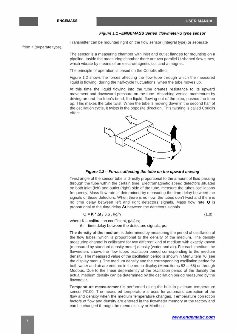
Figure 1.1 –ENGEMASS Series flowmeter-U type sensor
Transmitter can be mounted right on the flow sensor (integral type) or separate
from it (separate type).
The sensor is a measuring chamber with inlet and outlet flanges for mounting on a
pipeline. Inside the measuring chamber there are two parallel U-shaped flow tubes,
which vibrate by means of an electromagnetic coil and a magnet.
The principle of operation is based on the Coriolis effect.
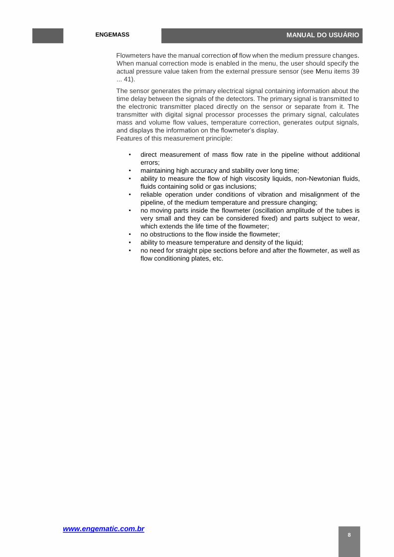
Figure 1.2 shows the forces affecting the flow tube through which the measured
liquid is flowing, during the half-cycle fluctuations, when the tube moves up.
At this time the liquid flowing into the tube creates resistance to its upward
movement and downward pressure on the tube. Absorbing vertical momentum by
driving around the tube’s bend, the liquid, flowing out of the pipe, pushes the tube
up. This makes the tube twist. When the tube is moving down in the second half of
the oscillation cycle, it twists in the opposite direction. This twisting is called Coriolis
effect.
Figure 1.2 – Forces affecting the tube on the upward moving
Twist angle of the sensor tube is directly proportional to the amount of fluid passing
through the tube within the certain time. Electromagnetic speed detectors situated
on both inlet (left) and outlet (right) side of the tube, measure the tubes oscillations
frequency. Mass flow rate is determined by measuring the time delay between the
signals of those detectors. When there is no flow, the tubes don’t twist and there is
no time delay between left and right detectors signals. Mass flow rate Q is
proportional to the time delay Δt between the detectors signals.
Q = K * Δt / 3.6 , kg/h (1.0)
where K – calibration coefficient, g/s/µs;
Δt – time delay between the detectors signals, µs.
The density of the medium is determined by measuring the period of oscillation of
the flow tubes, which is proportional to the density of the medium. The density
measuring channel is calibrated for two different kind of medium with exactly known
(measured by standard density meter) density (water and air). For each medium the
flowmeters shows the flow tubes oscillation period corresponding to the medium
density. The measured value of the oscillation period is shown in Menu item 70 (see
the display menu). The medium density and the corresponding oscillation period for
both water and air are entered in the menu display (Menu items 62 ... 65) or through
Modbus. Due to the linear dependency of the oscillation period of the density the
actual medium density can be determined by the oscillation period measured by the
flowmeter.
Temperature measurement is performed using the built-in platinum temperature
sensor Pt100. The measured temperature is used for automatic correction of the
flow and density when the medium temperature changes. Temperature correction
factors of flow and density are entered in the flowmeter memory at the factory and
can be changed through the menu display or Modbus.
www.engematic.com.br
ENGEMASS MANUAL DO USUÁRIO
8
Flowmeters have the manual correction of flow when the medium pressure changes.
When manual correction mode is enabled in the menu, the user should specify the
actual pressure value taken from the external pressure sensor (see Menu items 39
... 41).
The sensor generates the primary electrical signal containing information about the
time delay between the signals of the detectors. The primary signal is transmitted to
the electronic transmitter placed directly on the sensor or separate from it. The
transmitter with digital signal processor processes the primary signal, calculates
mass and volume flow values, temperature correction, generates output signals,
and displays the information on the flowmeter’s display.
Features of this measurement principle:
• direct measurement of mass flow rate in the pipeline without additional
errors;
• maintaining high accuracy and stability over long time;
• ability to measure the flow of high viscosity liquids, non-Newtonian fluids,
fluids containing solid or gas inclusions;
• reliable operation under conditions of vibration and misalignment of the
pipeline, of the medium temperature and pressure changing;
• no moving parts inside the flowmeter (oscillation amplitude of the tubes is
very small and they can be considered fixed) and parts subject to wear,
which extends the life time of the flowmeter;
• no obstructions to the flow inside the flowmeter;
• ability to measure temperature and density of the liquid;
• no need for straight pipe sections before and after the flowmeter, as well as
flow conditioning plates, etc.
www.engematic.com
ENGEMASS USER MANUAL
9
1.3 General specifications
1.3.1 Technical Performance Specification parameters
overview
Model:
-Integral type ENGEMASS-U……COM U shaped 2 tubes
-Integral type ENGEMASS-T……COM T shaped 2 tubes
-integral type ENGEMASS-M……COM Micro bent shaped 2 tubes
-integral type ENGEMASS-S……COM Micro bent shaped 2 tubes
-Remote type ENGEMASS-U……REM U shaped 2 tubes
-Remote type ENGEMASS-T……REM T shaped 2 tubes
-Remote type ENGEMASS-M……REM Micro bent shaped 2 tubes
-Remote type ENGEMASS-S……REM Super micro bent shaped 2 tubes
Fluid to be measured: Liquid, Gas or slurries Measurement items: Mass flow,
density, temperature and water cut %,concentration, volume flow and net flow
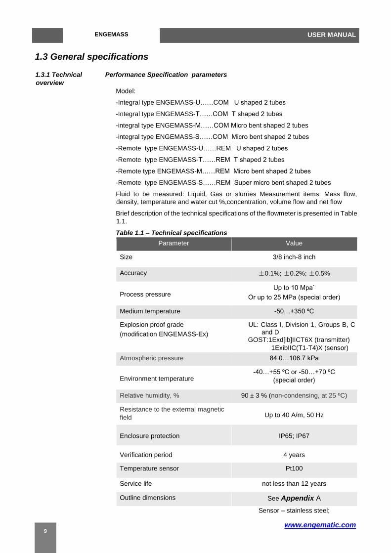
Brief description of the technical specifications of the flowmeter is presented in Table
1.1.
Table 1.1 – Technical specifications
Parameter Value
Size 3/8 inch-8 inch
Accuracy ±0.1%; ±0.2%; ±0.5%
Process pressure Up to 10 Mpа`
Or up to 25 MPа (special order)
Medium temperature -50…+350 ºС
Explosion proof grade
(modification ENGEMASS-Ex)
UL: Class I, Division 1, Groups B, C and D
GOST:1Exd[ib]IICT6X (transmitter)
1ExibIIC(T1-T4)X (sensor)
Atmospheric pressure 84.0…106.7 kPa
Environment temperature -40…+55 ºС or -50…+70 ºС
(special order)
Relative humidity, % 90 ± 3 % (non-condensing, at 25 ºC)
Resistance to the external magnetic
field Up to 40 A/m, 50 Hz
Enclosure protection IP65; IP67
Verification period 4 years
Temperature sensor Pt100
Service life not less than 12 years
Outline dimensions See Appendix A
Sensor – stainless steel;

www.engematic.com.br
ENGEMASS MANUAL DO USUÁRIO
10
Materials used
Transmitter – aluminum alloy.
Notes: 1. It is possible to produce flowmeters with special characteristics according to
the order.
2. Temperature range for OLED display is -40…+70 ºC.
1.3.2 Range of Flow ranges of the flowmeters with accuracy ±0.1%, ±0.2% and ±0.5% are measurement
shown in Table 1.2. Normal operation of the flowmeter guaranteed within the full flow range according to the
Table 1.2.
Operation of the flowmeter with the flow rate exceeding the upper limit of the full flow
range is not allowed.
The lower limit of the full measuring flow range depends on the parameters of the
medium, and should be specified in the order.
Table 1.2.1 – Measuring mass flow range for liquid(Metric unit)
Model: ENGEMASS-T and ENGEMASS-U
ENGEMASS-T: size 3/8 inch to 1 inch
ENGEMASS- U size 1 1/2 inch to 8 inch
Size(inch) Full flow range, kg/h
Accuracy flow range, kg/h Zero stability,
kg/h +/-0.1% +/-0.2% and +/-0.5%
3/8 10 – 1 000 70 – 1000 50 – 1000 0.13
1/2 30 – 3,000 150 – 3,000 100 – 3,000 0.38
1 80 – 8,000 400 – 8,000 300 – 8,000 1.00
11/2 320– 32,000 2,000 – 32,000 1500 – 32,000 4.00
2 500 – 50,000 3,500 – 50,000 2,500 – 50,000 6.25
3 1,400– 140,000 6,000 – 140,000 6,000 – 140,000 17.50
4 2,000– 200 000 15,000 – 200,000 10,000 – 200,000 25.00
6 5,000 – 500,000 35,000 – 500,000 25,000 – 500,000 62.50
8 10,000 – 1,000,000 700,000 – 1 000,000 50,000 – 1000,000 125.00
Table 1.2.2 – Measuring mass flow range for liquid(US unit)
Model: ENGEMASS-T and ENGEMASS-U
ENGEMASS-T: size 3/8 inch to 1 inch
ENGEMASS- U: size 1 1/2inch to 8 inch
Size(inch) Full flow range,
lb/m
Accuracy flow range, lb/m
+/-0.1% +/-0.2% and +/-0.5%
Zero stability,
lb/m
3/8 0.37– 37 2.57– 37 1.84– 37 0.00478
1/2 1.1– 110 5.51– 110 3.67– 110 0.01396
1 2.94 – 294 14.70 – 294 11.02 – 294 0.03674
11/2 11.76 – 1,176 73.49 – 1,176 55.12 – 1,176 0.14697
2 18.37 – 1,837 128.60 – 1,837 91.86 – 1,837 0.22965
3 51.44 – 5,144 220.46 – 5,144 220.46 – 5,144 0.64301
www.engematic.com
ENGEMASS USER MANUAL
11
4 73.49 – 7,349 551.16 – 7,349 367.44 – 7,349 0.91859
6 183.72 – 18,372 1,286.03 – 18,372 918.59 – 18,372 2.29648
8 367.44 –36,744 2,572.06 –36,744 1837.19 –36,744 4.59296
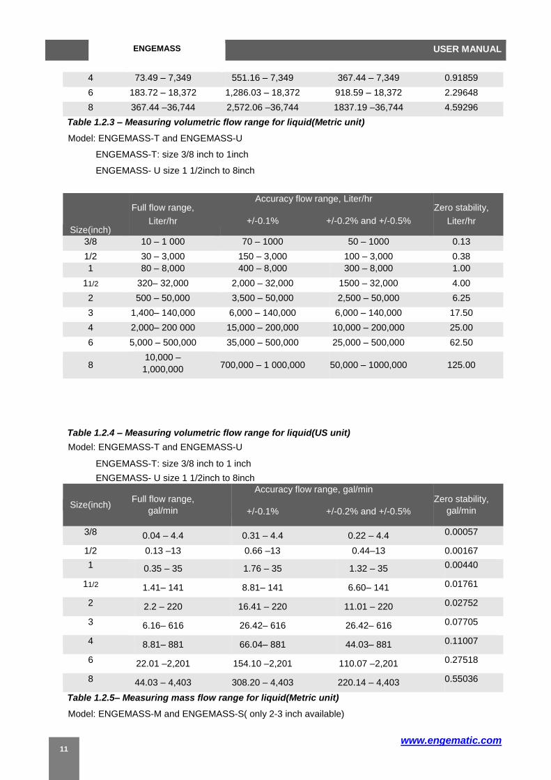
Table 1.2.3 – Measuring volumetric flow range for liquid(Metric unit)
Model: ENGEMASS-T and ENGEMASS-U
ENGEMASS-T: size 3/8 inch to 1inch
ENGEMASS- U size 1 1/2inch to 8inch
Size(inch)
Full flow range,
Liter/hr
Accuracy flow range, Liter/hr
+/-0.1% +/-0.2% and +/-0.5%
Zero stability,
Liter/hr
3/8 10 – 1 000 70 – 1000 50 – 1000 0.13
1/2 30 – 3,000 150 – 3,000 100 – 3,000 0.38
1 80 – 8,000 400 – 8,000 300 – 8,000 1.00
11/2 320– 32,000 2,000 – 32,000 1500 – 32,000 4.00
2 500 – 50,000 3,500 – 50,000 2,500 – 50,000 6.25
3 1,400– 140,000 6,000 – 140,000 6,000 – 140,000 17.50
4 2,000– 200 000 15,000 – 200,000 10,000 – 200,000 25.00
6 5,000 – 500,000 35,000 – 500,000 25,000 – 500,000 62.50
8 10,000 –
1,000,000 700,000 – 1 000,000 50,000 – 1000,000 125.00
Table 1.2.4 – Measuring volumetric flow range for liquid(US unit)
Model: ENGEMASS-T and ENGEMASS-U
ENGEMASS-T: size 3/8 inch to 1 inch
ENGEMASS- U size 1 1/2inch to 8inch
Size(inch) Full flow range,
gal/min
Accuracy flow range, gal/min
+/-0.1% +/-0.2% and +/-0.5%
Zero stability,
gal/min
3/8 0.04 – 4.4 0.31 – 4.4 0.22 – 4.4 0.00057
1/2 0.13 –13 0.66 –13 0.44–13 0.00167
1 0.35 – 35 1.76 – 35 1.32 – 35 0.00440
11/2 1.41– 141 8.81– 141 6.60– 141 0.01761
2 2.2 – 220 16.41 – 220 11.01 – 220 0.02752
3 6.16– 616 26.42– 616 26.42– 616 0.07705
4 8.81– 881 66.04– 881 44.03– 881 0.11007
6 22.01 –2,201 154.10 –2,201 110.07 –2,201 0.27518
8 44.03 – 4,403 308.20 – 4,403 220.14 – 4,403 0.55036
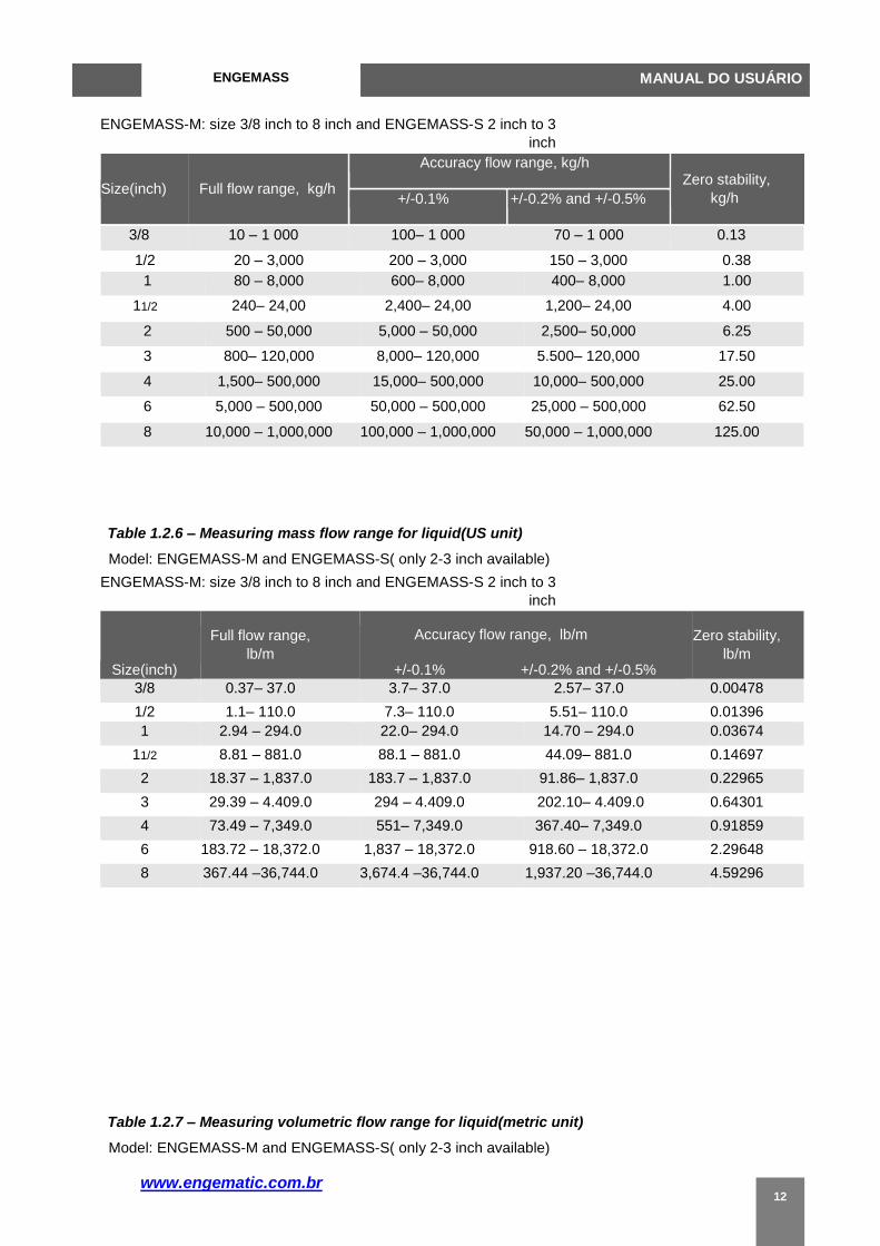
Table 1.2.5– Measuring mass flow range for liquid(Metric unit)
Model: ENGEMASS-M and ENGEMASS-S( only 2-3 inch available)
www.engematic.com.br
ENGEMASS MANUAL DO USUÁRIO
12
ENGEMASS-M: size 3/8 inch to 8 inch and ENGEMASS-S 2 inch to 3
inch
Size(inch) Full flow range, kg/h
Accuracy flow range, kg/h Zero stability,
kg/h +/-0.1% +/-0.2% and +/-0.5%
3/8 10 – 1 000 100– 1 000 70 – 1 000 0.13
1/2 20 – 3,000 200 – 3,000 150 – 3,000 0.38
1 80 – 8,000 600– 8,000 400– 8,000 1.00
11/2 240– 24,00 2,400– 24,00 1,200– 24,00 4.00
2 500 – 50,000 5,000 – 50,000 2,500– 50,000 6.25
3 800– 120,000 8,000– 120,000 5.500– 120,000 17.50
4 1,500– 500,000 15,000– 500,000 10,000– 500,000 25.00
6 5,000 – 500,000 50,000 – 500,000 25,000 – 500,000 62.50
8 10,000 – 1,000,000 100,000 – 1,000,000 50,000 – 1,000,000 125.00
Table 1.2.6 – Measuring mass flow range for liquid(US unit)
Model: ENGEMASS-M and ENGEMASS-S( only 2-3 inch available)
ENGEMASS-M: size 3/8 inch to 8 inch and ENGEMASS-S 2 inch to 3
inch
Size(inch)
Full flow range,
lb/m
Accuracy flow range, lb/m
+/-0.1% +/-0.2% and +/-0.5%
Zero stability,
lb/m
3/8 0.37– 37.0 3.7– 37.0 2.57– 37.0 0.00478
1/2 1.1– 110.0 7.3– 110.0 5.51– 110.0 0.01396
1 2.94 – 294.0 22.0– 294.0 14.70 – 294.0 0.03674
11/2 8.81 – 881.0 88.1 – 881.0 44.09– 881.0 0.14697
2 18.37 – 1,837.0 183.7 – 1,837.0 91.86– 1,837.0 0.22965
3 29.39 – 4.409.0 294 – 4.409.0 202.10– 4.409.0 0.64301
4 73.49 – 7,349.0 551– 7,349.0 367.40– 7,349.0 0.91859
6 183.72 – 18,372.0 1,837 – 18,372.0 918.60 – 18,372.0 2.29648
8 367.44 –36,744.0 3,674.4 –36,744.0 1,937.20 –36,744.0 4.59296
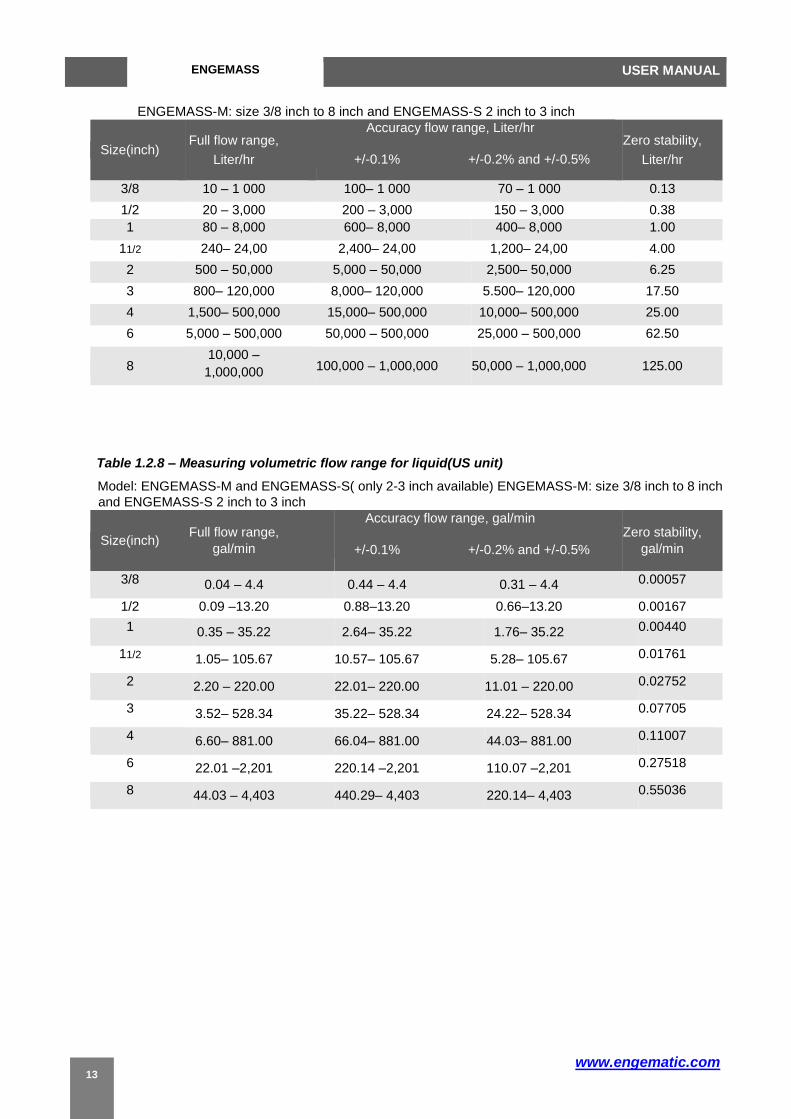
Table 1.2.7 – Measuring volumetric flow range for liquid(metric unit)
Model: ENGEMASS-M and ENGEMASS-S( only 2-3 inch available)
www.engematic.com
ENGEMASS USER MANUAL
13
ENGEMASS-M: size 3/8 inch to 8 inch and ENGEMASS-S 2 inch to 3 inch
Size(inch) Full flow range,
Liter/hr
Accuracy flow range, Liter/hr
+/-0.1% +/-0.2% and +/-0.5%
Zero stability,
Liter/hr
3/8 10 – 1 000 100– 1 000 70 – 1 000 0.13
1/2 20 – 3,000 200 – 3,000 150 – 3,000 0.38
1 80 – 8,000 600– 8,000 400– 8,000 1.00
11/2 240– 24,00 2,400– 24,00 1,200– 24,00 4.00
2 500 – 50,000 5,000 – 50,000 2,500– 50,000 6.25
3 800– 120,000 8,000– 120,000 5.500– 120,000 17.50
4 1,500– 500,000 15,000– 500,000 10,000– 500,000 25.00
6 5,000 – 500,000 50,000 – 500,000 25,000 – 500,000 62.50
8 10,000 –
1,000,000 100,000 – 1,000,000 50,000 – 1,000,000 125.00
Table 1.2.8 – Measuring volumetric flow range for liquid(US unit)
Model: ENGEMASS-M and ENGEMASS-S( only 2-3 inch available) ENGEMASS-M: size 3/8 inch to 8 inch
and ENGEMASS-S 2 inch to 3 inch
Size(inch) Full flow range,
gal/min
Accuracy flow range, gal/min
+/-0.1% +/-0.2% and +/-0.5%
Zero stability,
gal/min
3/8 0.04 – 4.4 0.44 – 4.4 0.31 – 4.4 0.00057
1/2 0.09 –13.20 0.88–13.20 0.66–13.20 0.00167
1 0.35 – 35.22 2.64– 35.22 1.76– 35.22 0.00440
11/2 1.05– 105.67 10.57– 105.67 5.28– 105.67 0.01761
2 2.20 – 220.00 22.01– 220.00 11.01 – 220.00 0.02752
3 3.52– 528.34 35.22– 528.34 24.22– 528.34 0.07705
4 6.60– 881.00 66.04– 881.00 44.03– 881.00 0.11007
6 22.01 –2,201 220.14 –2,201 110.07 –2,201 0.27518
8 44.03 – 4,403 440.29– 4,403 220.14– 4,403 0.55036

www.engematic.com
(1) The flow ranges are presented for water at temperature of 20…25 ºC, pressure of
0.1…0.2 MPa and density of 1,000 kg/m3 under standard conditions. For liquids
of different density the volumetric flow range should be calculated by dividing
these flow range limits under standard conditions by actual density value.
(2) If the measured flow rate is less than low flow cutoff value, the flowmeter will
indicate zero flow and accumulation of mass and volume will pause. Low flow
cutoff value is set to 1% of the maximum flow rate. Cutoff value can be changed
through the menu display or through Modbus.
(3) Flowmeter can measure flow over 1% of the upper limit of the full flow range but
measurement error in the range of 1% to the lower limit of the full flow range (2%)
is not standardized. However, this error can be estimated by the formula 1.1.
(4) Medium density measurement range is 200…3000 kg/m3.
1.3.3 Accuracy of Relative basic error of measurement of mass flow (mass) on pulse and digital output
measurement signals ( M) calculated as
M = ± [ 0 + (Z / QM) *100%], (1.1)
where 0 – accuracy class, %;
Z – zero stability (according to Table 1.2), kg/h;
QM – measured mass flow rate, kg/h.
Note – For the accuracy flow range, corresponding to a given accuracy class
(according to Table 1.2), the value of Z is assumed to be 0.
Absolute basic error of measurement of medium density ( ) is ± 1 kg/m3.
Absolute basic error of measurement of medium temperature is ± 1 °C.

www.engematic.com 13

www.engematic.com
Additional error of measurement of density, caused by a change of medium
temperature is ±0.03 kg/m3 for every 10 ºC of deviation from the density calibration
temperature.
Additional error of measurement of density, caused by a change of pressure is ±0.015
kg/m3 for every 100 kPa of deviation from the density calibration pressure.
Relative basic error of measurement of volumetric flow (volume) on pulse and
digital output signals ( V) calculated as
V = ± [ 0 + ( / *100% + (Z / QV) *100%], (1.2)
where 0 – accuracy class, %;
– absolute basic error of measurement of medium density, kg/m3;
– measured medium density, kg/m3;
Z – zero stability (according to Table 1.2), L/h;
QV – measured volumetric flow rate, L/h.
Note – For the accuracy flow range, corresponding to a given accuracy class
(according to Table 1.2), the value of Z is assumed to be 0.
Relative basic error of measurement of mass flow (mass) on current output signal
( IM) calculated as
IM = ± [| M| + 0.2*Imax / (4+16*QМ / QМmax)], (1.3)
where M – Relative basic error of measurement of mass flow (mass), %;
Imax = 20 mA – maximum value of current output signal;
QМ – measured mass flow rate, kg/h;
QМmax – upper limit of the full mass flow range, kg/h.
Relative basic error of measurement of volumetric flow (volume) on current output
signal ( IV) calculated as
IV = ± [| V| + 0.2*Imax / (4+16*QV / QVmax)], (1.4)
where V – Relative basic error of measurement of volumetric flow (volume), %;
Imax = 20 mA – maximum value of current output signal;
QV – measured volumetric flow rate, L/h;
QVmax – upper limit of the full volumetric flow range, L/h.
Additional error of measurement of mass (volumetric) flow rate, caused by a change
of medium temperature is ±0.05 % of the maximum flow rate for every 10 ºC of
deviation from the zero calibration temperature.
ENGEMASS-CMF USER MANUAL

www.engematic.com 14

www.engematic.com
Additional error of measurement of mass (volumetric) flow rate, caused by a
change of pressure is ±0.02 % of the maximum flow rate for every 100 kPa of
deviation from the zero calibration pressure.
The effect of changes in temperature and pressure can be adjusted by zero
calibration under the actual pressure and temperature (see paragraph 2.5.4 Zero
point adjustment”).
ENGEMASS-CMF USER MANUAL
www.engematic.com 19
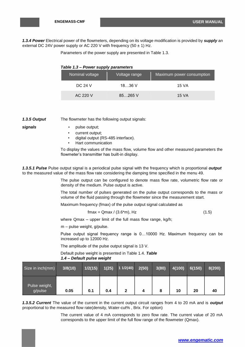
1.3.4 Power Electrical power of the flowmeters, depending on its voltage modification is provided by supply an
external DC 24V power supply or AC 220 V with frequency (50 ± 1) Hz.
Parameters of the power supply are presented in Table 1.3.
Table 1.3 – Power supply parameters
Nominal voltage Voltage range Maximum power consumption
DC 24 V 18…36 V 15 VA
AC 220 V 85…265 V 15 VA
1.3.5 Output The flowmeter has the following output signals:
signals • pulse output;
• current output;
• digital output (RS-485 interface).
• Hart communication
To display the values of the mass flow, volume flow and other measured parameters the
flowmeter’s transmitter has built-in display.
1.3.5.1 Pulse Pulse output signal is a periodical pulse signal with the frequency which is proportional output
to the measured value of the mass flow rate considering the damping time specified in the menu 49.
The pulse output can be configured to denote mass flow rate, volumetric flow rate or
density of the medium. Pulse output is active.
The total number of pulses generated on the pulse output corresponds to the mass or
volume of the fluid passing through the flowmeter since the measurement start.
Maximum frequency (fmax) of the pulse output signal calculated as
fmax = Qmax / (3.6*m), Hz (1.5)
where Qmax – upper limit of the full mass flow range, kg/h;
m – pulse weight, g/pulse.
Pulse output signal frequency range is 0…10000 Hz. Maximum frequency can be
increased up to 12000 Hz.
The amplitude of the pulse output signal is 13 V.
Default pulse weight is presented in Table 1.4. Table
1.4 – Default pulse weight
Size in inch(mm) 3/8(10) 1/2(15) 1(25) 1 1/2(40) 2(50) 3(80) 4(100) 6(150) 8(200)
Pulse weight,
g/pulse 0.05 0.1 0.4 2 4 8 10 20 40
1.3.5.2 Current The value of the current in the current output circuit ranges from 4 to 20 mA and is output
proportional to the measured flow rate(density, Water-cut% , Brix. For option)
The current value of 4 mA corresponds to zero flow rate. The current value of 20 mA
corresponds to the upper limit of the full flow range of the flowmeter (Qmax).
ENGEMASS-CMF USER MANUAL

ENGEMASS USER MANUAL
20
The current output can be configured to report mass flow rate, volumetric flow, water cut
% or density of the medium.
Current output is active.
The current signal parameters are presented in Table 1.5. Table
1.5 – Current output signal parameters
Current output signal
Current value 4…20 mA
Load resistance 250…600 Ohm
1.3.5.3 Digital Digital interface complies with the requirements EIA/TIA-422-B and recommendations output
RTU V.11 and provides the opportunity of networking and transferring of all measured parameters. The digital
interface specifications are presented in Table 1.6.
Table 1.6 – Digital interface specifications
Digital interface
Standard EIA RS-485
Data transfer protocol Modbus RTU
Data transfer baud rate 1200, 2400, 4800, 9600 bit/s
Maximum distance 300 m
Data format 8 data bits, 1 start bit, no parity bit, 2 stop bits (default).
Data format can be changed in the menus 30, 31.
The following measured parameters can be transmitted through the digital interface: mass
(volume) flow rate, mass (volume), density and temperature of the medium.
Digital interface can also be used to calibrate and to configure the flowmeter.
Flowmeter supports two versions of the Modbus register map:
• «GPE» register map version 2.хх is supported by the «GPE-Integrator» software
and set as default at factory;
• «ProLink» register map version 3.хх compatible with ProLink II software from
Micro motion.
Register map and description for «GPE» version 2.хх are presented in the Appendix , for
«ProLink» version 3.хх – in the Appendix .
Register map version switching can be performed by the «GPE-Integrator» or changing
the value of the corresponding Modbus register (see Appendix ) using third party serial
port tools.

21
1.3.6 Display The flowmeter’s OLED graphic display contains 4 lines with 166 symbols per line. The following
measured parameters can be displayed:
• Mass flow rate;
• Volumetric flow rate;
• Medium density;
• Medium temperature;
• Total mass; • Total volume.
• Water cut%( For special order only)
• Brix. ( For special order only)
Display operation is provided by the means of three optical seensor buttons below the
display. Display operation described in the paragraph 2.5.3 Display operating”.
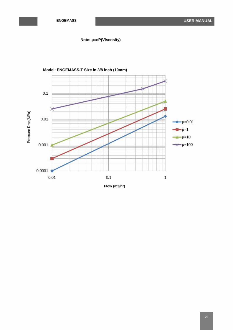
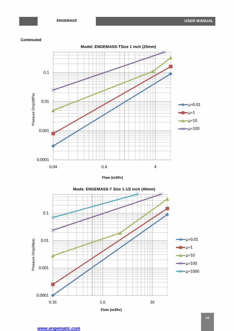
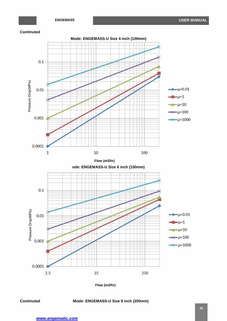
1.4 Pressure drop
The pressure drop on the flowmeter (ΔP) at maximmum flow rate, pressure and temperature is not more than
0.13 MPa for watter medium.
In the process of measurement flow of liquids it iss necessary to consider the
cavitation effect (liquid boiling), which may occcur in certain conditions of the
flow. Cavitation may cause the flowmeteer work abnormally. To prevent this,
it is necessary to keep the certain preessure at the distance of 5*DN after the
flowmeter. That pressure must bbe not less than critical pressure (Рcr)
calculated as
Рcr = 2.9 ΔР + 1.3 рν , kPa
where ΔP – pressure drop on the flowmeter, kPa; рν – saturated steam
pressure at working conditions (background
information), kPa.
If the pressure calculated by this formula exceedss the actual pressure in the
pipeline, a safety valve should be installed to inncrease the pressure.
Please refer to following pressure drop grapph before engineering
design and application
ENGEMASS USER MANUAL
ENGEMASS USER MANUAL
22
Note: µ=cP(Viscosity)
Model: ENGEMASS-T Size in 3/8 inch (10mm)
Flow (m3/hr)

23
Model: ENGEMASS-T Size 1/2 inch (15mm)
Flow (m3/hr)
www.engematic.com
ENGEMASS USER MANUAL
24
Continuted
Model: ENGEMASS-TSize 1 inch (25mm)
Flow (m3/hr)
Mode: ENGEMASS-T Size 1-1/2 inch (40mm)
Flow (m3/hr)

www.engematic.com
ENGEMASS-CMF USER MANUAL
25
Continuted
Model: ENGEMASS-U Size 2 inch (50mm)
Flow (m3/hr)
Mode: ENGEMASS-U Size 3 inch (80mm)
Flow (m3/hr)
www.engematic.com
ENGEMASS USER MANUAL
26
Continuted
Mode: ENGEMASS-U Size 4 inch (100mm)
Flow (m3/hr)
ode: ENGEMASS-U Size 6 inch (150mm)
Flow (m3/hr)
Continuted Mode: ENGEMASS-U Size 8 inch (200mm)

www.engematic.com
ENGEMASS-CMF USER MANUAL
27
Flow (m3/hr)
Typical accuracy, turndown, and pressure drop with Model: ENGEMASS-M size 2 inch(50mm)
Flow (m3/hr)
Turndown from Max. flowrate 20:1 15:1 10:1 1.5:1 1:1
Accuracy +/-% 0.2 0.2 0.1 0.1 0.1
Pressure drop 0.001 0.0015 0.002 0.1 0.17
www.engematic.com
ENGEMASS USER MANUAL
28
1.5 Explosion protection
The Flowmeter complied with Underwriters Laboratories Inc. for telemetering equipment for use in
Hazardous locations
Class I, Groups C and D; Class II, Groups E, F and G; Class I, Groups A, B, C and D, Division 2.
Intrinsically safe mass flow sensors, for use in Class I, Groups C and D; Class II, Groups E, F and G
hazardous locations and also suitable for Class I, Groups A, B,
C and D, Division 2 hazardous locations
Booster Amplifier for use in Class I, Division 1, Groups C and D; Class I, Division 2, Groups A, B, C and D; Class
II,
Division 1, Groups E, F and G, Hazardous Locations Providing Intrinsically Safe Circuits
Also the transmitter , sensor and booster amplifier complied with GOST R 51330.1, and the input and output
"intrinsically safe" level «ib» complied with GOST R 51330.10.
The flowmeters of explosion-proof modification "GPE-ENGEMASS-Ex» have a integral type of protection
"flameproof enclosure" complied with GOST R 51330.1, and the input and output "intrinsically safe" level
«ib» complied with GOST R 51330.10. The sensor explosion proof grade is showed in Table 1.7.
Table 1.7 – Sensor explosion proof grade
Temperature code Explosion proof grade
“100” 1Ex ibIICT4X
“200” 1Ex ibIICT3X
“350” 1Ex ibIICT1X
Transmitter explosion proof grade is 1ExdibIICT6X.
Explosion proof grade is written on the name plates attached to the body of the sensor of explosion-proof
modification and to the transmitter.
The name plates’ appearance is showed on flowmeter ordered.
The "Х" letter in the explosion proof grade means the special requirements:
- the measured medium temperature must not exceed the maximum temperature according to the
explosion proof grade temperature group;
- explosion protection is provided under pressure not exceeding the maximum allowable pressure for
the given modification;
- connection of external circuits to the flowmeter must be implemented through the cable entries
complied with GOST R 51330.1;
- unused cable entry must be closed with the end cap supplied by the flowmeter’s manufacturer or
other end cap complied with GOST R 51330.1;
- connection of the external devices to the pulse, current and digital outputs of the flowmeters of “Ex”
modification must be implemented in accordance with GOST R 51330.1.
Explosion protection type of "flameproof enclosure" is implemented by putting the electrical parts of the
flowmeter into the flameproof enclosure in accordance with GOST R 51330.1, which prevents the explosion
from coming out of the flowmeter into the explosive environment.
Explosion protection of the enclosure is ensured by the following means:
– the housing case withstands the explosion test at the test pressure of 4 times the pressure of the
explosion;
www.engematic.com
ENGEMASS-CMF USER MANUAL
29
– axial thread length and number of full turns of thread engagement comply with GOST R 51330.1
requirements;
– the gaps and lengths of flat and cylindrical flameproof joints
comply with GOST R 51330.1 requirements;
– maximum flowmeter’s surface temperature in working conditions must not exceed the temperature
range in accordance to GOST R 51330.0 for the temperature groups:
- Т4 for the flowmeters with temperature modification code «100»;
- Т3 for the flowmeters with temperature modification code «200»; - Т1 for the
flowmeters with temperature modification code «350».
Explosion protection type of input and output "intrinsically safe" circuit level «ib» is ensured by the following
means:
– external power supply and connection of the external devices to the pulse, current and digital outputs
of the flowmeters of “Ex” modification must be implemented in accordance with GOST R 51330.1;
– electric load of anti-spark circuit elements of the flowmeter does not exceed 2/3 of their certified
values;
– the values of parameters of the left/right signal coils, drive coil and the temperature sensor circuits
do not exceed the limits in accordance with GOST R 51330.10;
– spark safety barrier with Zener diodes is applied;
– electrical clearances and creepage distances comply with GOST R 51330.10. Insulation resistance
between the sensor outer shell and electrical circuits elements can withstand the testing voltage of 500 V AC rms;
– internal capacity and inductance of the circuit do not accumulate energy, dangerous for spark ignition
gas mixtures of category IIC;
– current-conducting elements and electronic components of the flowmeter circuit are protected from
the environment influence with the shell, which provides the protection degree IP 65 according to GOST 14254.
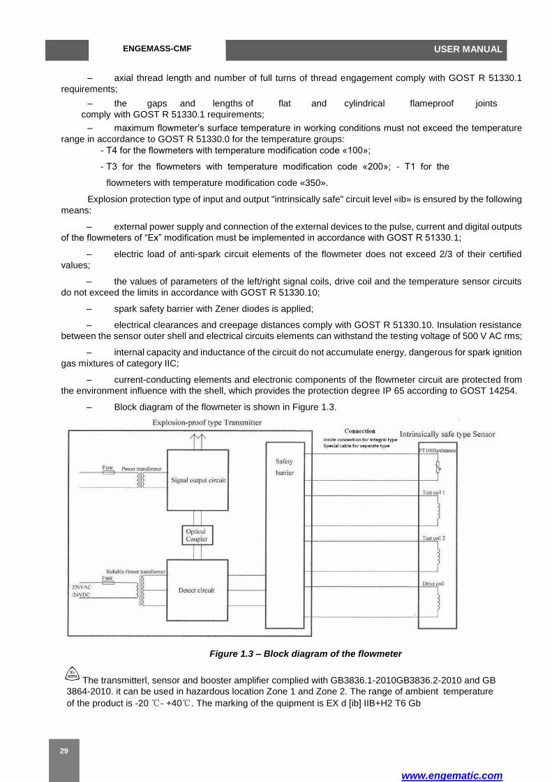
– Block diagram of the flowmeter is shown in Figure 1.3.
Figure 1.3 – Block diagram of the flowmeter
The transmitterl, sensor and booster amplifier complied with GB3836.1-2010GB3836.2-2010 and GB
3864-2010. it can be used in hazardous location Zone 1 and Zone 2. The range of ambient temperature
of the product is -20 ℃- +40℃. The marking of the quipment is EX d [ib] IIB+H2 T6 Gb

www.engematic.com
ENGEMASS USER MANUAL
30
Input and output parameters of intrinsically safe circuits are shown in Tables 1.8 and 1.9.
Table 1.8 – Input parameters of intrinsically safe circuits
Maximum input current Ii, mA 72 70 72
Maximum input capacity Ci, pF 50 50 50
Maximum input inductance Li, mH 2.2 3.5 0.010
Maximum input power Pi, W 0.097 0.184 0.097
Table 1.9 - Output parameters of intrinsically safe circuits
Maximum output voltage Uo, V 5.4 10.5 5.4
Maximum output current Io, mA 72 70 72
Maximum output capacity Co, µF 10 1 10
Maximum output inductance Lo, mH 5 4.5 5
Maximum output power Po, W 0.097 0.184 0.097
Parameters of the sensor coil windings are shown in Table 1.10.
Table 1.10 – Coil windings parameters
Coil Wire diameter, mm Number of
turns
Resistance,
Ohm
Left / right signal coils 0.13 500 20 ± 0.5
Drive coil (DN10 – DN40) 0.13 300 11 ± 0.5
Drive coil (DN50 –
0.27 300 8 ± 0.5
DN200)
Maximum length of the connection cable for the separate type flowmeter is 300 m.
Drive coil power circuits are electrically isolated from other circuits by means of the undamaged transformer
according to GOST R 51330.10. Insulation between primary and secondary windings can withstand voltage
of at least 1.5 kV.
Ambient temperature for the flowmeters of “Ex” modification must be between -20 and +40 ºC.
Parameter name
Parameter value
Left / right signal coils
Drive coil Temperature
sensor
Maximum input voltage Ui, V 5.4 10.5 5.4
Parameter name
Parameter value for the circuit of
Left / right coil power
Drive coil power
Temperature sensor power

www.engematic.com
ENGEMASS-CMF USER MANUAL
31
1.6 HAZARDOUS AREA CLASSIFICATIONS
UL
All models with junction box Ambient temperature: +104 °F (+40 °C) maximum
Class I, Div. 1, Groups C and D
Class I, Div. 2, Groups A, B, C, and D
Class II, Div.1, Groups E, F, and G
Flowmeter’s parameters are marked on the name plates attached to to the body of the sensor and the top s ide
of the transmitter. Flowmeter has the following name plates:
1. Main name plate with technical parameters on sensor
2. transmitter nameplate
The main name plate is produced according to Figure 1.4 and contains data presented in Table 1.11.
Figure 1.4 – Main name plate
Flowmeter’s parameters are marked on the name plates attached to the top side of the transmitter and to the
body of the sensor. Flowmeter has the following name plates:
3. Main name plate with technical parameters
4. Sensor name plate with sensor explosion proof information.
The main name plate is produced according to Figure 1.4 and contains data presented in Table 1.11.

www.engematic.com
ENGEMASS USER MANUAL
32
Table 1.11 – Main name plate data
Item № Description
1 Trademark of the manufacturer
2 Flowmeter name
3 approval marks
4 Maximum process pressure (max)
5 Accuracy class
6 Model sierie
7 Power supply voltage
8 IP protection grade
9 Explosion protection grade and Ex-sign
10 Information about manufacturer
11 Serial number
12 Flow Cal( K factor)
13 Temperature range of the measured medium (Twork)
14 Full flow range (Q)
15 Meter size
16 CE directive
CAUTION!
Before installation of the flowmeter, make sure that the information on the name plates conforms to the
data in the order.
After verification procedure the flowmeter is sealed. Sealing is performed using the seal and wire threaded through
the holes in the front cover of the transmitter.
It’s also allowed to use a sealing tape attached to both the transmitter shell and the front cover of the transmitter.
1.7 Delivery set The base delivery set and the accessories for the flowmeter are shown in Figures 1.6, 1.7
and in Tables 1.12, 1.13.

www.engematic.com
ENGEMASS-CMF USER MANUAL
33
Figure 1.6 – Base delivery set
Table 1.12 – Base delivery set
Item
№ Description Base delivery
set
Special
order
1 Coriolis Mass Flowmeter
ENGEMASS-series + Cable
length
2 User manual CD
3 Calibration report CD
4 Packing box +
5 Inspection report CD

www.engematic.com
ENGEMASS USER MANUAL
34
Table 1.13 - Accessories
Item № Description
1 Connection kit (flanges, gaskets, stud bolts, nuts, washers)
2 Flowmeter’s replacement mounting part
CAUTION!
Upon receipt of the flowmeter it is necessary to:
• Check the packaging box for damage;
• Make sure that delivery set is complete;
• Make sure the flowmeter model matches the order data.
If the package is damaged, delivery set or flowmeter model doesn’t match the
order you should draw up a statement.
www.engematic.com
ENGEMASS-CMF USER MANUAL
35
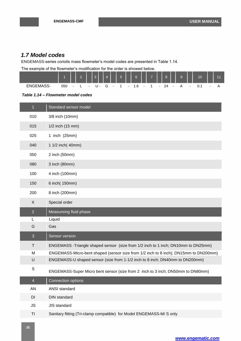
1.7 Model codes ENGEMASS-series coriolis mass flowmeter’s model codes are presented in Table 1.14.
The example of the flowmeter’s modification for the order is showed below.
1 2 3 4 5 6 7 8 9 10 11
ENGEMASS- 050 - L - U - G - 1 - 1.6 - 1 - 24 - A - 0.1 - A
Table 1.14 – Flowmeter model codes
1 Standard sensor model
010 3/8 inch (10mm)
015 1/2 inch (15 mm)
025 1 inch (25mm)
040 1 1/2 inch( 40mm)
050 2 inch (50mm)
080 3 inch (80mm)
100 4 inch (100mm)
150 6 inch( 150mm)
200 8 inch (200mm)
X Special order
2 Measureing fluid phase
L Liquid
G Gas
3 Sensor version
T ENGEMASS -Triangle shaped sensor (size from 1/2 inch to 1 inch; DN10mm to DN25mm)
M ENGEMASS-Micro-bent shaped (sensor size from 1/2 inch to 8 inch); DN15mm to DN200mm)
U ENGEMASS-U shaped sensor (size from 1-1/2 inch to 8 inch; DN40mm to DN200mm)
S
ENGEMASS-Super Micro bent sensor (size from 2 inch to 3 inch; DN50mm to DN80mm)
4 Connection options
AN ANSI standard
DI DIN standard
JS JIS standard
TI Sanitary fitting (Tri-clamp compatible) for Model ENGEMASS-M/ S only

www.engematic.com
ENGEMASS USER MANUAL
36
X
Special order
5 Max. Process Pressure
1.6 227psi (PN:1.6MPa)
2.5 355psi(PN:2.5MPa)
4.0 568psi(PN:4.0MPa)
6.4 908psi(PN:6.4MPa)
10 1420psi(PN:10MPa)
X Special order
6 Max. Process temperature and intructure
1 Process temperature -50…+125 °С( Integral type)
2 Process temperature -50…+200 °С (separate type only)
3 Process temperature -50…+350 °С (separate type only)
X
Special order ( for LNG)
7 Aprroval
NX Non-Explosion
EX Class I, Groups C and D; Class II, Groups E, F and G hazardous locations
Exdib II CT3~T6 for transducer, Exdib II CT6 transmitter (for remote)
8 Power supply
1 DC 18~36V
2 AC85~265V
9 Output signals
P Pulse/4 to 20mA
R RS485+4 to 20mA+Pulse
H
Hart+ 4 to 20mA+Pulse
10 Accuracy
0.1 Accuracy ±0.1%
0.2 Accuracy ±0.2%
0.5 Accuracy ±0.5%
Notes: 1) for separate type mass Flowmeter , please confirm the special cable length when ordering.
2) ENGEMASS Model selection guider software is recommend to use.

www.engematic.com
ENGEMASS-CMF USER MANUAL
37
2 OPERATION AND MAINTENANCE
2.1 Model selection recommendations
One of the most important conditions for reliable operation of the flowmeter and to obtain reliable measurement
results is correspondence of the flowmeter’s modification to the process parameters.
The list of the process parameters required for optimal flowmeter modification
selection is presented in Table 2.1. Table 2.1 – Process parameters for
modification selection
Item
№ Process parameter
1 Measured medium name:
2 Composition and percentage of liquid components:
3 Composition and percentage of solid impurities in fluid:
4 Composition and percentage of gas inclusions in fluid:
5 Measured medium density:
6 Measured medium viscosity:
7 Flow range:
8 Required accuracy:
9 Process temperature:
10 Process pressure:
11 Allowable pressure drop:
12 Presence of regulation and control components in the system:
13 Process connection size:
14 Pipeline orientation at the installation place:
15 Ambient temperature:
16 Explosion protection grade and requirements:
CAUTION!
To avoid erroneous self-dependent selection of the modification of the flowmeter
please send the completed questionnaire to the nearest GPE company
representative.
Flowmeter size should be selected according to the actual flow rates in the pipeline,
which may differ from the calculated (design) values. Flowmeter size should be
chosen so that the actual flow rate of the medium was in the second third of the flow
range. Therefore, nominal diameter (DN) of the flowmeter can be either equal or less
than the nominal diameter of the pipeline.
www.engematic.com
ENGEMASS USER MANUAL
38
When mismatch pipeline diameter and the nominal diameter of the flowmeter
tapered transitions can be used. They can be made independently, at that to ensure
minimum loss of pressure, the central cone angle must not exceed 30 ºC.
2.2 Safety precautions
Installation, operation, maintenance of flowmeters should be performed by
persons studied this manual and safety instructions for working with electrical devices.
All operations on calibration and usage of flowmeters must comply with the requirements
for protection against static electricity.
Installation of flowmeter in the pipeline and its removal from the pipeline should be
performed without pressure in the pipeline and with the power supply switched off.
Electrical connection should also be performed only when the power supply is
switched off.
During the installation, commissioning and maintenance shall be prohibited:
• replacement of electronic components when the flowmeter is powered on;
• connecting the flowmeter to the power supply with output voltage other than
specified in this manual;
• using electrical devices and tools without protective grounding and also in case of
their malfunctions.
During installation the hazardous factors are:
• power supply voltage of 220V AC or higher (in case of the external power supply
located in close vicinity of the installation place);
• excess pressure in the pipeline; • high temperature of the medium.
Operation of flowmeters of “Ex” modification must be performed in accordance with
the requirements of Chapter 7.3 of the “Electrical Installations Code” and other
regulations of using of electrical equipment in explosive environment.
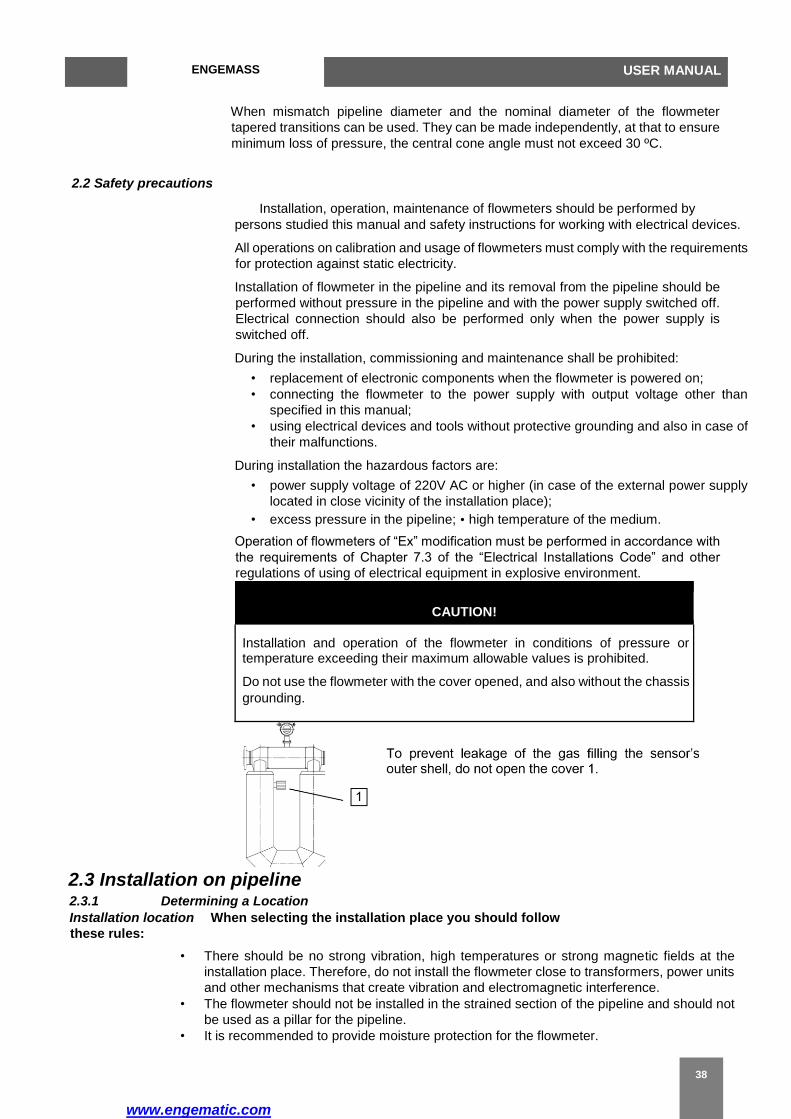
CAUTION!
Installation and operation of the flowmeter in conditions of pressure or temperature exceeding their maximum allowable values is prohibited.
Do not use the flowmeter with the cover opened, and also without the chassis
grounding.
2.3 Installation on pipeline 2.3.1 Determining a Location Installation location When selecting the installation place you should follow
these rules:
• There should be no strong vibration, high temperatures or strong magnetic fields at the
installation place. Therefore, do not install the flowmeter close to transformers, power units
and other mechanisms that create vibration and electromagnetic interference.
• The flowmeter should not be installed in the strained section of the pipeline and should not
be used as a pillar for the pipeline.
• It is recommended to provide moisture protection for the flowmeter.
www.engematic.com
ENGEMASS-CMF USER MANUAL
39
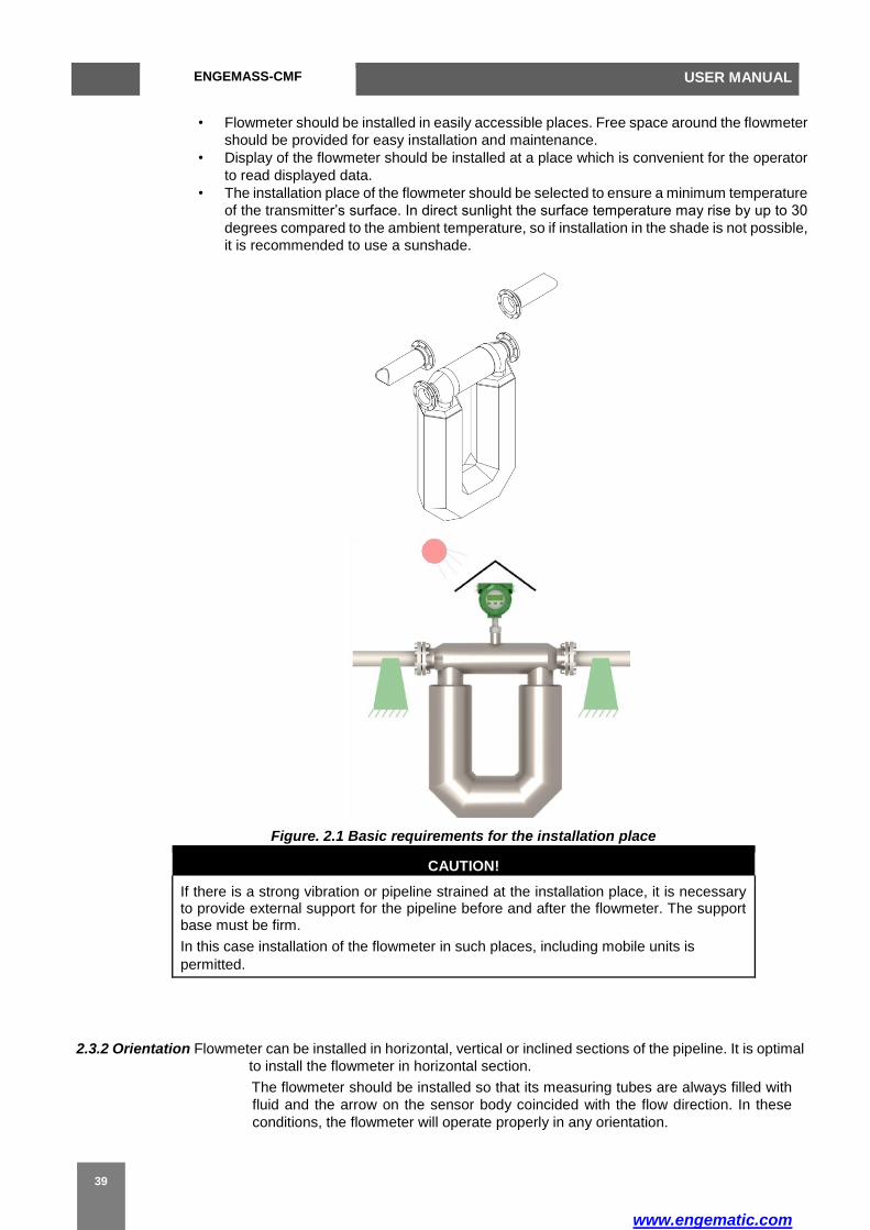
• Flowmeter should be installed in easily accessible places. Free space around the flowmeter
should be provided for easy installation and maintenance.
• Display of the flowmeter should be installed at a place which is convenient for the operator
to read displayed data.
• The installation place of the flowmeter should be selected to ensure a minimum temperature
of the transmitter’s surface. In direct sunlight the surface temperature may rise by up to 30
degrees compared to the ambient temperature, so if installation in the shade is not possible,
it is recommended to use a sunshade.
Figure. 2.1 Basic requirements for the installation place
CAUTION!
If there is a strong vibration or pipeline strained at the installation place, it is necessary to provide external support for the pipeline before and after the flowmeter. The support base must be firm.
In this case installation of the flowmeter in such places, including mobile units is
permitted.
2.3.2 Orientation Flowmeter can be installed in horizontal, vertical or inclined sections of the pipeline. It is optimal
to install the flowmeter in horizontal section.
The flowmeter should be installed so that its measuring tubes are always filled with
fluid and the arrow on the sensor body coincided with the flow direction. In these
conditions, the flowmeter will operate properly in any orientation.

www.engematic.com
ENGEMASS USER MANUAL
40
Flowmeter does not require collateral straight pipeline sections before and after the
flowmeter, nor installation of additional equipment to level the flow profile (flow
conditioning plates, etc.). But if two or more flowmeter are installed in the same
section of the pipeline, the distance between them should be at least 2 m.
Installation recommendations are presented in Figure 2.2.
Figure 2.2 Recommendations for installation
Liquid/slurry Application Gas Application Liquid/slurry Application
Tubes down Tubes up
Flag mount
Horizontal Pipeline Horizontal
Pipeline Vertical Pipeline
Flow direction arrow
The sensor has a flow direction arrow (on the sensor ) to help you configure the transmitter for flow direction.
If possible, install the sensor so that the flow direction arrow matches actual process flow.
Vertical pipeline
If the sensor is installed in a vertical pipeline, liquids and slurries should flow upward through the sensor. Gases
may flow upward or downward.
Table 2.2 – Notes for Figure 2.2
Pic № Recommendations
1 It is recommended to install the flowmeter tubes downward to improve their
filling with fluid and to prevent accumulation of gas in them.
2
For vertical or inclined pipeline orientation it is recommended to install the
flowmeter in a pipeline section with the upward flow direction to improve
filling of the pipe with fluid.
In the event of bending pipe it is recommended to install the flowmeter in the lower
section of the pipeline.
Do not install the flowmeter on a horizontal pipe before the drainage section with free flow,
because in this case filling the flowmeter’s tubes wit fluid is not guaranteed.

www.engematic.com
ENGEMASS-CMF USER MANUAL
41
2.3.3 Pipeline To prepare for the installation of the flowmeter, it is necessary:
preparation • Check the completeness of the connection kit and conformity of all
mounting parts to the flowmeter’s modification;
• Cut the pipeline section of length Linst
Linst = Lm + 2*Lg + 2*Lf, (2.1)
where Lm – flowmeter length (see Appendix );
Lg – gasket thickness;
Lf – connection kit flange thickness minus depth of landing on the pipeline;
• Install connection kit flanges on the pipeline;
• Using the flowmeter’s replacement mounting part, fix and center flanges
and weld them to the pipeline.
CAUTION!
In the process of installation the flowmeter may be used instead of the replacement mounting part only in the following cases:
- installation is carried out using a gas welding;
- when installing using an electric arc welding,the power source is
connected in a way that prevents the welding current to run through the
flowmeter - see Figure 2.3.
Right Wrong
Figure 2.3 Connecting the power source for arc welding using the flowmeter
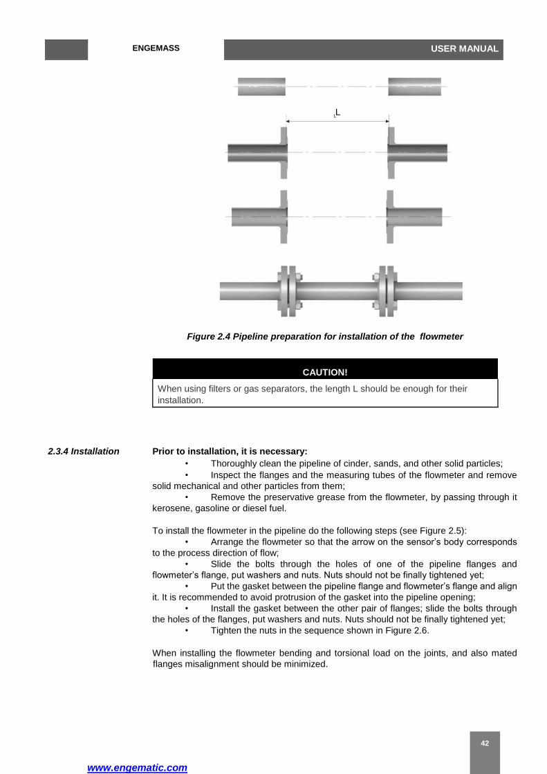
As a result, the installation place must appear as shown in Figure 2.4, where the length L
is the sum of the length of the flowmeter and thickness of two gaskets.
www.engematic.com
ENGEMASS USER MANUAL
42
Figure 2.4 Pipeline preparation for installation of the flowmeter
CAUTION!
When using filters or gas separators, the length L should be enough for their
installation.
2.3.4 Installation Prior to installation, it is necessary:
• Thoroughly clean the pipeline of cinder, sands, and other solid particles;
• Inspect the flanges and the measuring tubes of the flowmeter and remove
solid mechanical and other particles from them;
• Remove the preservative grease from the flowmeter, by passing through it
kerosene, gasoline or diesel fuel.
To install the flowmeter in the pipeline do the following steps (see Figure 2.5):
• Arrange the flowmeter so that the arrow on the sensor’s body corresponds
to the process direction of flow;
• Slide the bolts through the holes of one of the pipeline flanges and
flowmeter’s flange, put washers and nuts. Nuts should not be finally tightened yet;
• Put the gasket between the pipeline flange and flowmeter’s flange and align
it. It is recommended to avoid protrusion of the gasket into the pipeline opening;
• Install the gasket between the other pair of flanges; slide the bolts through
the holes of the flanges, put washers and nuts. Nuts should not be finally tightened yet;
• Tighten the nuts in the sequence shown in Figure 2.6.
When installing the flowmeter bending and torsional load on the joints, and also mated
flanges misalignment should be minimized.
L

www.engematic.com
ENGEMASS-CMF USER MANUAL
43
Figure 2.5 Installation of the flowmeter in the pipeline
Table 2.3 – Notes for Figure 2.5
Item № Mounting part
1 flanges
2 Connection kit flanges
3 Gaskets
4 Nuts
5 Washers
6 Bolts (or stud bolts)

www.engematic.com
ENGEMASS USER MANUAL
44
Figure 2.6 - The sequence of tightening the flange bolts
Transmitter of the separate type of the flowmeter can be mounted as shown in Figure
2.7. Transmitter can be mounted with brackets or clamps to the rack, pipe or wall.
Figure 2.7 – Installation of transmitter of separate type illustration
Table 2.4 – Notes for Figure 2.7
Item № Mounting part
1 Transmitter base
2 Bolts
3 Clamp
4 Nuts

www.engematic.com
ENGEMASS-CMF USER MANUAL
45
CAUTION!
Do not install the transmitter with the cable entry directed vertically upwards.
2.3.5 Thermal If thermal insulation of the pipeline and the flowmeter is necessary, see the insulation recommendations in Figure 2.8.
Figure 2.8 – Recommendation for thermal insulation of the flowmeter
2.3.6 Cooling For high temperature modification of the flowmeter (with medium temperature above +200 °C)
possibility of external cooling is provided (see Figure 2.9).
www.engematic.com
ENGEMASS USER MANUAL
46
DN15-25 DN40-200
Figure 2.9 – External cooling supply
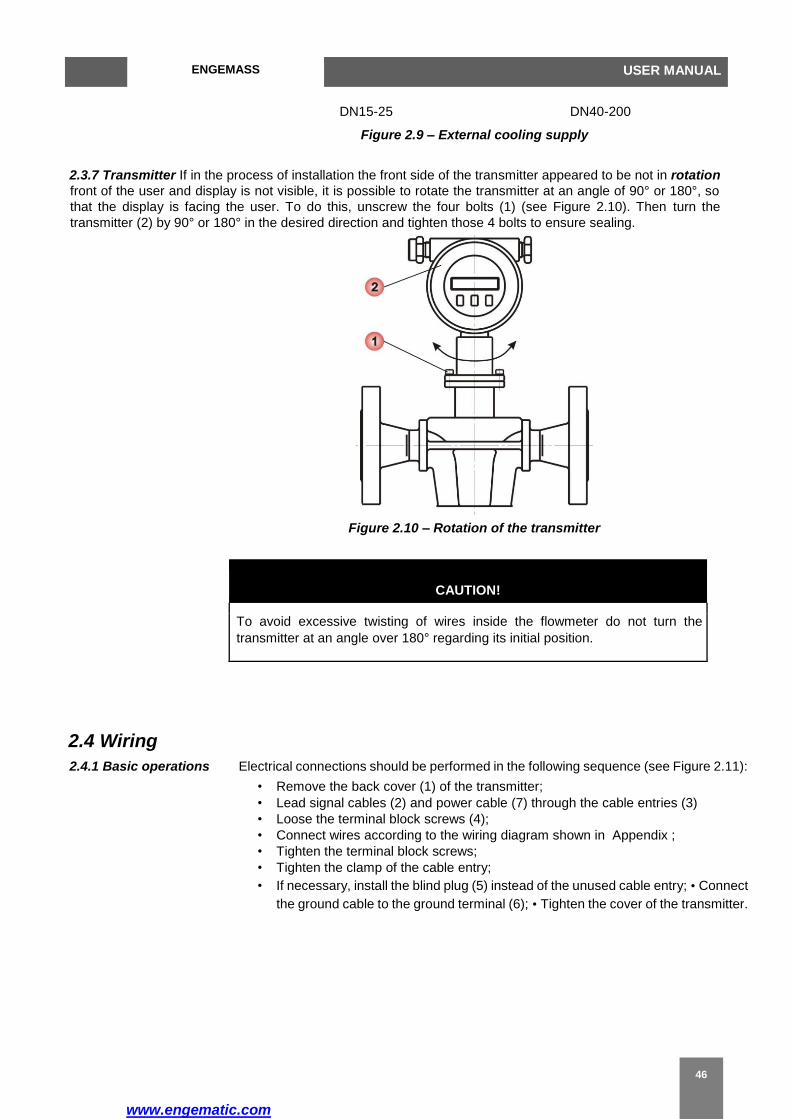
2.3.7 Transmitter If in the process of installation the front side of the transmitter appeared to be not in rotation front of the user and display is not visible, it is possible to rotate the transmitter at an angle of 90° or 180°, so
that the display is facing the user. To do this, unscrew the four bolts (1) (see Figure 2.10). Then turn the
transmitter (2) by 90° or 180° in the desired direction and tighten those 4 bolts to ensure sealing.
Figure 2.10 – Rotation of the transmitter
CAUTION!
To avoid excessive twisting of wires inside the flowmeter do not turn the
transmitter at an angle over 180° regarding its initial position.
2.4 Wiring
2.4.1 Basic operations Electrical connections should be performed in the following sequence (see Figure 2.11):
• Remove the back cover (1) of the transmitter;
• Lead signal cables (2) and power cable (7) through the cable entries (3)
• Loose the terminal block screws (4);
• Connect wires according to the wiring diagram shown in Appendix ;
• Tighten the terminal block screws;
• Tighten the clamp of the cable entry;
• If necessary, install the blind plug (5) instead of the unused cable entry; • Connect
the ground cable to the ground terminal (6); • Tighten the cover of the transmitter.

www.engematic.com
ENGEMASS-CMF USER MANUAL
47
Figure 2.11 - Electrical connection of the flowmeter
Table 2.5 – Notes for Figure 2.11
Item №. Description
1 Back cover of the transmitter
2 Signal cable
3 Cable entries
4 Wiring Terminal block
5 Blind plug
6 Ground terminal
7 Power cable
2
Maximum length of the power cable is 300 m with minimum wire section 0.8 mm
(AWG18). Connecting to the current and pulse outputs should be performed with a
twisted
2 pair wire with the maximum length of 150 m and minimal wire section 0.5
mm (AWG20).
Sensor and transmitter of the flowmeter of separate type are connected through a
special 9-core shielded cable with maximum length of 300 m. Connection diagram is
shown in Figure C.1 of Appendix .After mounting and electrical connection the zero
point adjustment should be performed (see paragraph 2.5.4 “Zero point adjustment”).
CAUTION!
When using the flowmeter in hazardous areas,
apply the requirements for explosion protction
provided in paragraph 2.4.2 "Installation with
explosion protection"
www.engematic.com
ENGEMASS USER MANUAL
48
2.4.2 Installation with
explosion protection Installation of flowmeters in explosive environment must be performed in accordance with requirements of:
– This manual;
– Section 3.4 of “Operational Code for Electrical
Installations”;
– Section 7.3 of “Electrical Installations Code”;
– GOST R 51330.0;
– GOST R 51330.1;
– GOST R 51330.10;
– Instruction BCH332-74/MMCC (“Instructions
for installation of electrical equipment, power and
lighting lines in hazardous areas”); – Other
regulations in force within the enterprise.
During installation you should pay attention to the specific operating conditions mentioned in Section 1.5 "Explosion protection".
Before installation the flowmeter should be inspected. You should pay special attention to explosion proof grade labels, warning labels, make sure that there is no damage to the flameproof shell and flow sensor. Also make sure that grounding terminal and the seals for cables and covers are available and in good condition, also check the connecting cables condition.
Upon completion of the electrical installation the electrical resistance of the ground line should be checked. It must not exceed 1 Ohm. A copper wire with section of at least 2.5 mm2 (AWG13) should be used for grounding.
Unused cable entry must be closed with the end cap supplied by the flowmeter’s manufacturer or other end cap complied with GOST R 51330.1;
During installation, check the explosion-proof surfaces of mounting parts involved in providing explosion protection. Scratches, dents, chips on the explosion-proof surfaces of those parts (which are in the explosion path), are not permitted.
After the completion of the electrical connections it is
necessary to close the transmitter covers firmly and put
the latch lock on the covers.
www.engematic.com
ENGEMASS-CMF USER MANUAL
49
2.4.3 Wiring recommendations
During electrical connection of the flowmeter you should follow these recommendations:
• Wire cores must be cleaned and fixed on terminals to prevent a short circuit between each other and the body of the flowmeter (ground);
• It is recommended to use separate power supplies or a multichannel power supply with isolated channels to power the flowmeter and each of its outputs;
• If it is necessary to calculate the load resistor value, the total load impedance should be calculated as the sum of the cable resistance, external load resistance, resistance of safety barriers, load resistance of the secondary equipment;
• To minimize interference when transmitting of analog output signal 4-20 mA and digital signal it is recommended to use a shielded twisted pair cable. Grounding of the cable should be provided only on one side of the cable (near the power supply);
• It is not recommended to lay the signal cables
in the same conduit with power wires, and also near
sources of strong electromagnetic fields. If necessary,
grounding of signal wiring can be done at any point in
the signal circuit. For example, it is possible to ground
the negative terminal of the power supply. The
electronics housing is grounded to the sensor housing.
2.4.4 Waterproofing The flowmeter meets all the requirements for moisture
protection grade specified in the "Technical
Specifications" section.
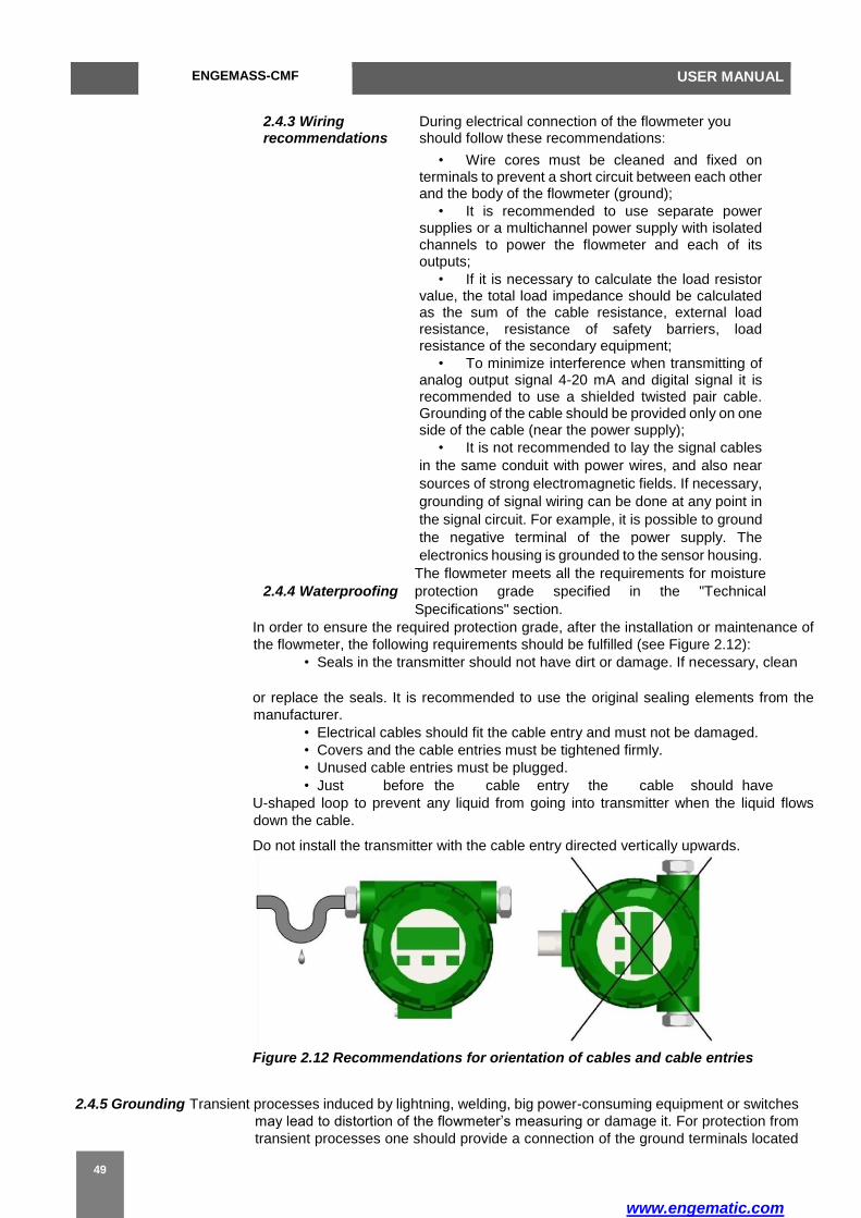
In order to ensure the required protection grade, after the installation or maintenance of
the flowmeter, the following requirements should be fulfilled (see Figure 2.12):
• Seals in the transmitter should not have dirt or damage. If necessary, clean
or replace the seals. It is recommended to use the original sealing elements from the
manufacturer.
• Electrical cables should fit the cable entry and must not be damaged.
• Covers and the cable entries must be tightened firmly.
• Unused cable entries must be plugged.
• Just before the cable entry the cable should have
U-shaped loop to prevent any liquid from going into transmitter when the liquid flows
down the cable.
Do not install the transmitter with the cable entry directed vertically upwards.
Figure 2.12 Recommendations for orientation of cables and cable entries
2.4.5 Grounding Transient processes induced by lightning, welding, big power-consuming equipment or switches
may lead to distortion of the flowmeter’s measuring or damage it. For protection from
transient processes one should provide a connection of the ground terminals located
www.engematic.com
ENGEMASS USER MANUAL
50
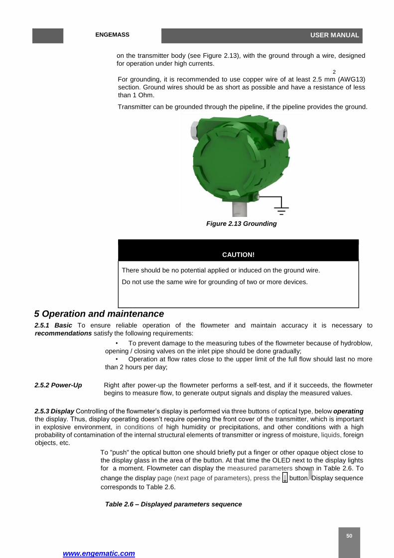
on the transmitter body (see Figure 2.13), with the ground through a wire, designed
for operation under high currents.
2
For grounding, it is recommended to use copper wire of at least 2.5 mm (AWG13)
section. Ground wires should be as short as possible and have a resistance of less
than 1 Ohm.
Transmitter can be grounded through the pipeline, if the pipeline provides the ground.
Figure 2.13 Grounding
CAUTION!
There should be no potential applied or induced on the ground wire.
Do not use the same wire for grounding of two or more devices.
5 Operation and maintenance 2.5.1 Basic To ensure reliable operation of the flowmeter and maintain accuracy it is necessary to
recommendations satisfy the following requirements:
• To prevent damage to the measuring tubes of the flowmeter because of hydroblow,
opening / closing valves on the inlet pipe should be done gradually;
• Operation at flow rates close to the upper limit of the full flow should last no more
than 2 hours per day;
2.5.2 Power-Up Right after power-up the flowmeter performs a self-test, and if it succeeds, the flowmeter
begins to measure flow, to generate output signals and display the measured values.
2.5.3 Display Controlling of the flowmeter’s display is performed via three buttons of optical type, below operating
the display. Thus, display operating doesn’t require opening the front cover of the transmitter, which is important
in explosive environment, in conditions of high humidity or precipitations, and other conditions with a high
probability of contamination of the internal structural elements of transmitter or ingress of moisture, liquids, foreign
objects, etc.
To "push" the optical button one should briefly put a finger or other opaque object close to
the display glass in the area of the button. At that time the OLED next to the display lights
for a moment. Flowmeter can display the measured parameters shown in Table 2.6. To
change the display page (next page of parameters), press the ↓ button. Display sequence
corresponds to Table 2.6.
Table 2.6 – Displayed parameters sequence
www.engematic.com
ENGEMASS-CMF USER MANUAL
51
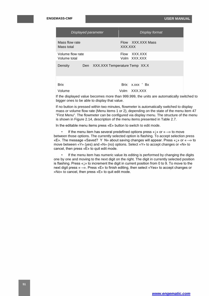
Displayed parameter Display format
Mass flow rate
Mass total
Flow XXX.XXX Mass
XXX.XXX
Volume flow rate Flow XXX.XXX
Volume total Volm XXX.XXX
Density Den XXX.XXX Temperature Temp XX.X
Brix Brix x.xxx °Bx
Volume Volm XXX.XXX
If the displayed value becomes more than 999.999, the units are automatically switched to
bigger ones to be able to display that value.
If no button is pressed within two minutes, flowmeter is automatically switched to display
mass or volume flow rate (Menu items 1 or 2), depending on the state of the menu item 47
"First Menu". The flowmeter can be configured via display menu. The structure of the menu
is shown in Figure 2.14, description of the menu items presented in Table 2.7.
In the editable menu items press «Е» button to switch to edit mode.
• If the menu item has several predefined options press «↓» or «→» to move
between those options. The currently selected option is flashing. To accept selection press
«Е». The message «Saved? Y N» about saving changes will appear. Press «↓» or «→» to
move between «Y» (yes) and «N» (no) options. Select «Y» to accept changes or «N» to
cancel, then press «Е» to quit edit mode.
• If the menu item has numeric value its editing is performed by changing the digits
one by one and moving to the next digit on the right. The digit in currently selected position
is flashing. Press «↓» to increment the digit in current position from 0 to 9. To move to the
next digit press «→». Press «Е» to finish editing, then select «Yes» to accept changes or
«No» to cancel, then press «Е» to quit edit mode.
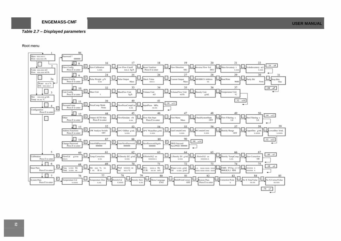
ENGEMASS-CMF USER MANUAL
Table 2.7 – Displayed parameters

ENGEMASS-CMF
USER MANUAL
Figure 2.14 Display menu structure( Refer to our latest version per P.O)
Menu
item Indication format Button
actions Description
Measured parameters display
0 GPE Ver.2.23 and later. 2012.03 →1 Version and data of electronics. Press”→” at first screen and it’s showed on flowmeter’s powerup.
1 Flow ХХХ.Х Mass ХХХ.ХХХX ↓2, →0
Total mass and mass flow rate.
Mass flow units:
Kg lb
Ton(Metric ton,default setting)
Mass flow rate units:
t/d t/h(default
setting)
Kg/h
Kg/m
lb/h lb/m

ENGEMASS-CMF USER MANUAL
2 Flow ХХХ.Х Volm ХХХ.ХХХX ↓3, →1
Total volume and instant volumetric flow rate.
Volumetric flow units:
GL( US
Gallon) BBL
m3
Total volume units:
m3/d
BL/d( BBL/day)
GL/h (US gallon/hr)
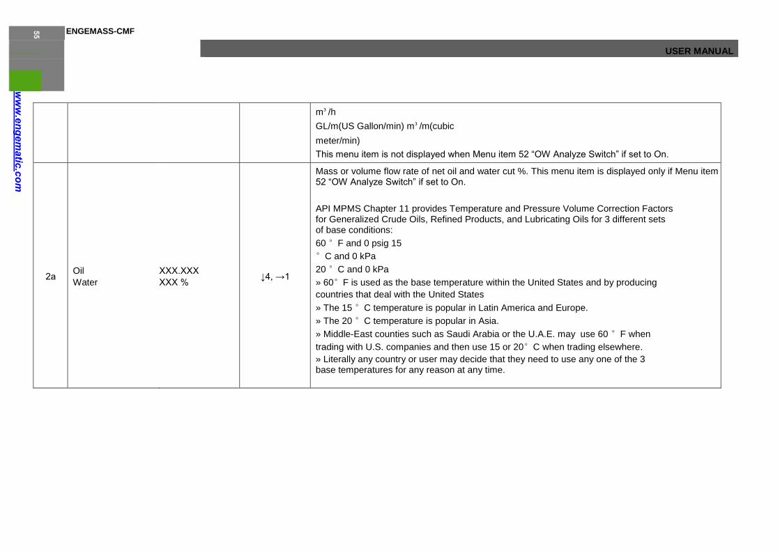
ENGEMASS-CMF
USER MANUAL
m³/h
GL/m(US Gallon/min) m³/m(cubic
meter/min)
This menu item is not displayed when Menu item 52 “OW Analyze Switch” if set to On.
2а Oil
Water
ХХХ.ХХХ
ХХХ % ↓4, →1
Mass or volume flow rate of net oil and water cut %. This menu item is displayed only if Menu item 52 “OW Analyze Switch” if set to On.
API MPMS Chapter 11 provides Temperature and Pressure Volume Correction Factors for Generalized Crude Oils, Refined Products, and Lubricating Oils for 3 different sets of base conditions:
60 °F and 0 psig 15
°C and 0 kPa
20 °C and 0 kPa
» 60°F is used as the base temperature within the United States and by producing
countries that deal with the United States
» The 15 °C temperature is popular in Latin America and Europe.
» The 20 °C temperature is popular in Asia.
» Middle-East counties such as Saudi Arabia or the U.A.E. may use 60 °F when
trading with U.S. companies and then use 15 or 20°C when trading elsewhere.
» Literally any country or user may decide that they need to use any one of the 3 base temperatures for any reason at any time.
ENGEMASS-CMF USER MANUAL
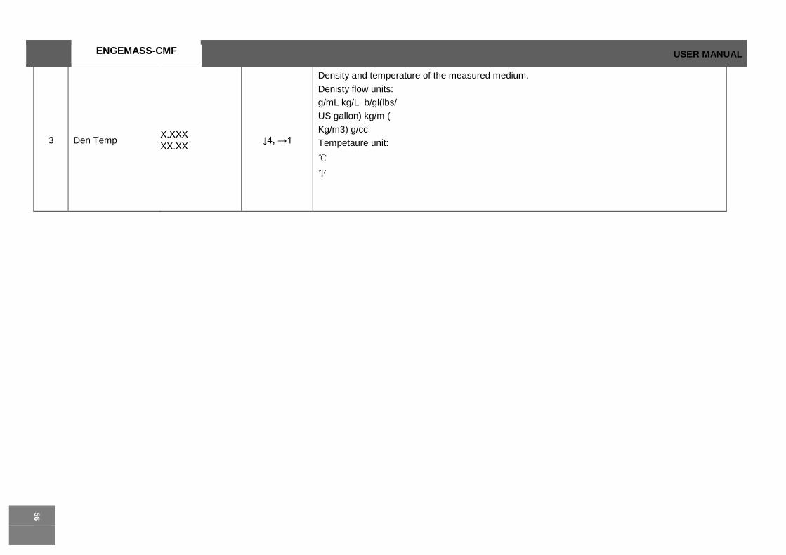
3 Den Temp Х.ХХХ
ХХ.ХХ ↓4, →1
Density and temperature of the measured medium.
Denisty flow units:
g/mL kg/L b/gl(lbs/
US gallon) kg/m (
Kg/m3) g/cc
Tempetaure unit:
℃
℉
ENGEMASS-CMF
USER MANUAL
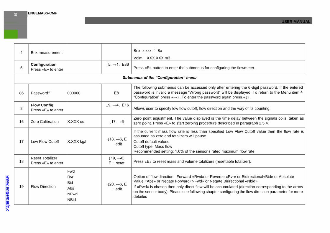
4 Brix measurement Brix x.xxx °Bx
Volm XXX.XXX m3
5 Configuration
Press «E» to enter
↓5, →1, Е86 Press «E» button to enter the submenus for configuring the flowmeter.
Submenus of the “Configuration” menu
86 Password? 000000 Е8
The following submenus can be accessed only after entering the 6-digit password. If the entered
password is invalid a message “Wrong password” will be displayed. To return to the Menu item 4
“Configuration” press «→». To enter the password again press «↓».
8 Flow Config
Press «E» to enter
↓9, →4, Е16 Allows user to specify low flow cutoff, flow direction and the way of its counting.
16 Zero Calibration Х.ХХХ us ↓17, →6 Zero point adjustment. The value displayed is the time delay between the signals coils, taken as
zero point. Press «Е» to start zeroing procedure described in paragraph 2.5.4.
17 Low Flow Cutoff Х.ХХХ kg/h ↓18, →6, Е
− edit
If the current mass flow rate is less than specified Low Flow Cutoff value then the flow rate is assumed as zero and totalizers will pause.
Cutoff default values
Cutoff type: Mass flow
Recommended setting: 1.0% of the sensor’s rated maximum flow rate
18 Reset Totalizer
Press «E» to enter
↓19, →6,
Е − reset Press «Е» to reset mass and volume totalizers (resettable totalizer).
19 Flow Direction
Fwd
Rvr
Bid
Abs
NFwd
NBid
↓20, →6, Е
− edit
Option of flow direction, Forward «Rwd» or Reverse «Rvr» or Bidirectional«Bid» or Absolute Value «Abs» or Negate Forward«NFwd» or Negate Birirectional «Nbid»
If «Rwd» is chosen then only direct flow will be accumulated (direction corresponding to the arrow
on the sensor body). Please see following chapter configuring the flow direction parameter for more
detailes
ENGEMASS-CMF USER MANUAL
Configuring the flow direction parameter The flow direction parameter controls how the transmitter reports flow rate and how flow is added to or subtracted from the totalizers, under conditions of forward flow, reverse flow, or zero flow. • Forward (positive) flow moves in the direction of the arrow on the sensor.
• Reverse (negative) flow moves in the direction opposite of the arrow on the sensor.
ENGEMASS-CMF
USER MANUAL
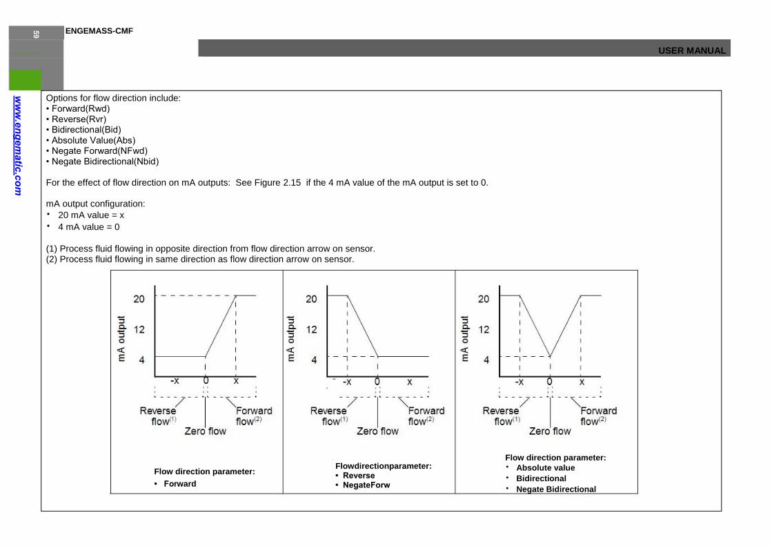
Options for flow direction include: • Forward(Rwd) • Reverse(Rvr) • Bidirectional(Bid) • Absolute Value(Abs) • Negate Forward(NFwd) • Negate Bidirectional(Nbid) For the effect of flow direction on mA outputs: See Figure 2.15 if the 4 mA value of the mA output is set to 0. mA output configuration:
• 20 mA value = x
• 4 mA value = 0
(1) Process fluid flowing in opposite direct ion from flow direction arrow on sensor. (2) Process fluid flowing in same direct ion as flow direction arrow on sensor.
Flow direction parameter:
• Fo r ward
Flowdirectionparameter: • Reverse • NegateForw
Flow direction parameter: • Absolute value • Bidirectional • Negate Bidirectional

ENGEMASS-CMF USER MANUAL

ENGEMASS-CMF
USER MANUAL
ENGEMASS-CMF USER MANUAL
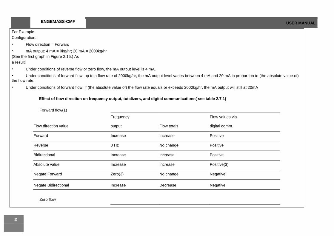
For Example
Configuration:
• Flow direction = Forward
• mA output: 4 mA = 0kg/hr; 20 mA = 2000kg/hr
(See the first graph in Figure 2.15.) As
a result:
• Under conditions of reverse flow or zero flow, the mA output level is 4 mA.
• Under conditions of forward flow, up to a flow rate of 2000kg/hr, the mA output level varies between 4 mA and 20 mA in proportion to (the absolute value of)
the flow rate.
• Under conditions of forward flow, if (the absolute value of) the flow rate equals or exceeds 2000kg/hr, the mA output will still at 20mA
Effect of flow direction on frequency output, totalizers, and digital communications( see table 2.7.1)
Forward flow(1)
Frequency Flow values via
Flow direction value output Flow totals digital comm.
Forward Increase Increase Positive
Reverse 0 Hz No change Positive
Bidirectional Increase Increase Positive
Absolute value Increase Increase Positive(3)
Negate Forward Zero(3) No change Negative
Negate Bidirectional Increase Decrease Negative
Zero flow
ENGEMASS-CMF
USER MANUAL
Frequency Flow values via
Flow direction value output Flow totals digital comm.

ENGEMASS-CMF USER MANUAL

ENGEMASS-CMF
USER MANUAL
ENGEMASS-CMF USER MANUAL
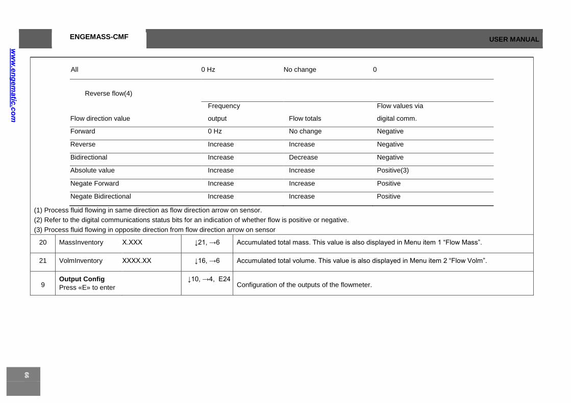
All 0 Hz No change 0
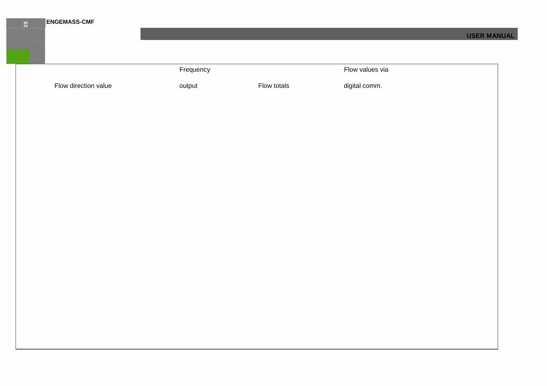
Reverse flow(4)
Frequency Flow values via
Flow direction value output Flow totals digital comm.
Forward 0 Hz No change Negative
Reverse Increase Increase Negative
Bidirectional Increase Decrease Negative
Absolute value Increase Increase Positive(3)
Negate Forward Increase Increase Positive
Negate Bidirectional Increase Increase Positive
(1) Process fluid flowing in same direction as flow direction arrow on sensor.
(2) Refer to the digital communications status bits for an indication of whether flow is positive or negative.
(3) Process fluid flowing in opposite direction from flow direction arrow on sensor
20 MassInventory Х.ХХХ ↓21, →6 Accumulated total mass. This value is also displayed in Menu item 1 “Flow Mass”.
21 VolmInventory ХХХХ.ХХ ↓16, →6 Accumulated total volume. This value is also displayed in Menu item 2 “Flow Volm”.
9 Output Config
Press «E» to enter
↓10, →4, Е24 Configuration of the outputs of the flowmeter.
ENGEMASS-CMF
USER MANUAL
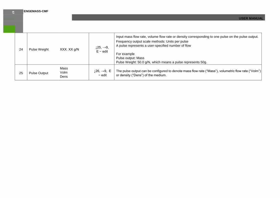
24 Pulse Weight ХХХ. ХХ g/N ↓25, →9,
Е − edit
Input mass flow rate, volume flow rate or density corresponding to one pulse on the pulse output.
Frequency output scale methods: Units per pulse
A pulse represents a user-specified number of flow
For example
Pulse output: Mass
Pulse Weight: 50.0 g/N, which means a pulse represents 50g.
25 Pulse Output
Mass
Volm
Dens
↓26, →9, Е
− edit
The pulse output can be configured to denote mass flow rate (“Mass”), volumetric flow rate (“Volm”)
or density (“Dens”) of the medium.

ENGEMASS-CMF USER MANUAL

ENGEMASS-CMF
USER MANUAL
26 20mA Value ХХХ.Х ↓27, →9,
Е − edit Input mass flow rate, volume flow rate or density corresponding to 20mA on the current output.
27 Current Output
Mass
Volm
Dens
Water cut%
Brix.
↓28, →9,
Е − edit
The current output can be configured to denote mass flow rate (“Mass”), volumetric flow rate (“Volm”)
, density (“Dens”) of the medium and water cut %. And Brix °
28 MODBUS
Address ХХХ ↓29, →9,
Е − edit Address of the flowmeter in Modbus network.
29 Baud Rate
9600
4800
2400
1200
↓30, →9,
Е − edit Data transfer baud rate in Modbus network.
30 Parity Bit
No
Even
Odd
↓31, →9,
Е − edit
Parity control in data transfer protocol. Select «NO» for no parity; «Even» for 1 even parity bit;
«Odd» for 1 odd parity bit.
31 Stop Bits One
Two
↓24, →9,
Е − edit
Select one or two stop bits in data transfer protocol in Modbus network.
10 Unit Config
Press «E» to enter
↓11, →4,
E32 Select units for parameters displayed in the menu items 1, 2, 3.
32 Mass Unit
Kg,
lb,
Ton( metric)
↓33, →10,
Е − edit Select units for mass totalizer.
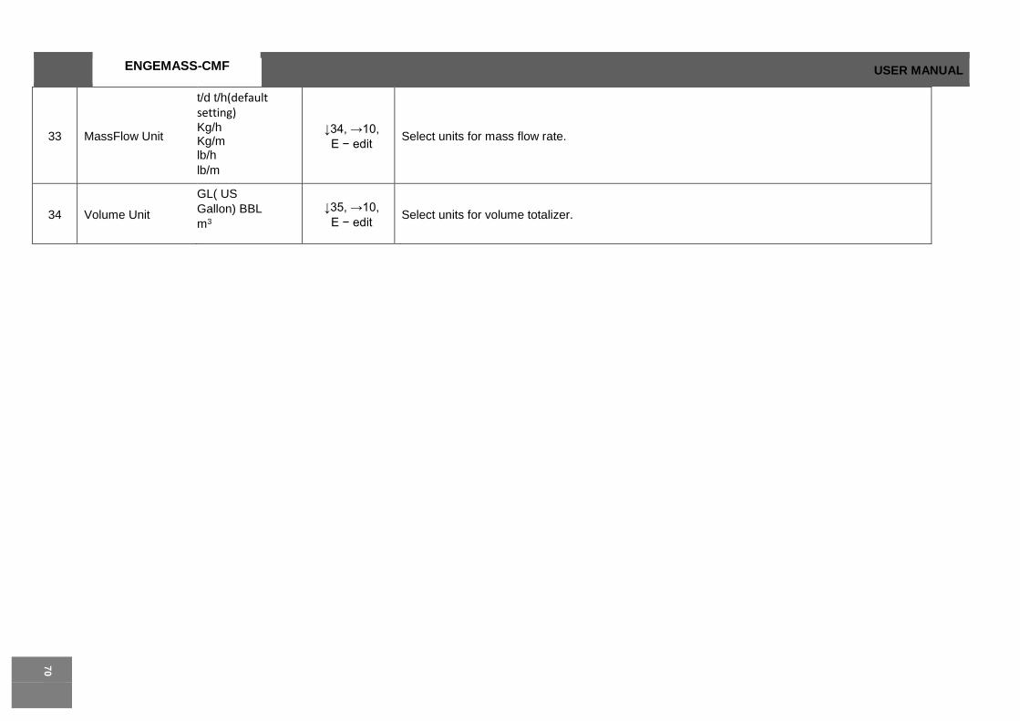
ENGEMASS-CMF USER MANUAL
33 MassFlow Unit
t/d t/h(default setting) Kg/h Kg/m lb/h
lb/m
↓34, →10,
Е − edit Select units for mass flow rate.
34 Volume Unit
GL( US
Gallon) BBL
m3
↓35, →10,
Е − edit Select units for volume totalizer.

ENGEMASS-CMF
USER MANUAL
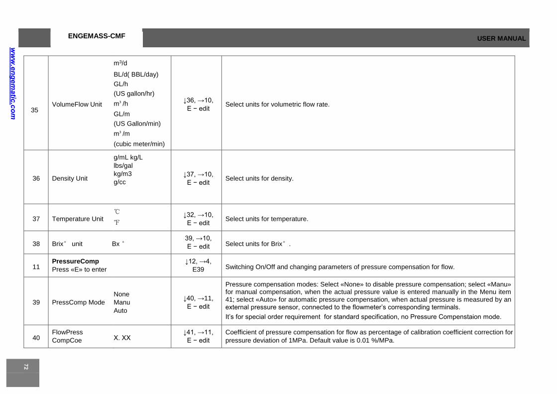
ENGEMASS-CMF USER MANUAL
35 VolumeFlow Unit
m3/d
BL/d( BBL/day)
GL/h
(US gallon/hr)
m³/h
GL/m
(US Gallon/min)
m³/m
(cubic meter/min)
↓36, →10,
Е − edit Select units for volumetric flow rate.
36 Density Unit
g/mL kg/L
lbs/gal
kg/m3
g/cc ↓37, →10,
Е − edit Select units for density.
37 Temperature Unit ℃
℉
↓32, →10,
Е − edit Select units for temperature.
38 Brix° unit Bx ° 39, →10,
Е − edit Select units for Brix°.
11 PressureComp
Press «E» to enter
↓12, →4,
E39 Switching On/Off and changing parameters of pressure compensation for flow.
39 PressComp Mode
None
Manu
Auto
↓40, →11,
Е − edit
Pressure compensation modes: Select «None» to disable pressure compensation; select «Manu» for manual compensation, when the actual pressure value is entered manually in the Menu item 41; select «Auto» for automatic pressure compensation, when actual pressure is measured by an external pressure sensor, connected to the flowmeter’s corresponding terminals.
It’s for special order requirement for standard specification, no Pressure Compenstaion mode.
40 FlowPress
CompCoe Х. ХХ ↓41, →11,
Е − edit
Coefficient of pressure compensation for flow as percentage of calibration coefficient correction for
pressure deviation of 1MPa. Default value is 0.01 %/MPa.
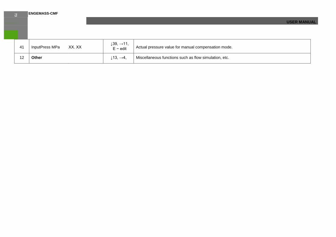
ENGEMASS-CMF
USER MANUAL
41 InputPress MPa ХХ. ХХ ↓39, →11,
Е − edit Actual pressure value for manual compensation mode.
12 Other ↓13, →4, Miscellaneous functions such as flow simulation, etc.

ENGEMASS-CMF USER MANUAL
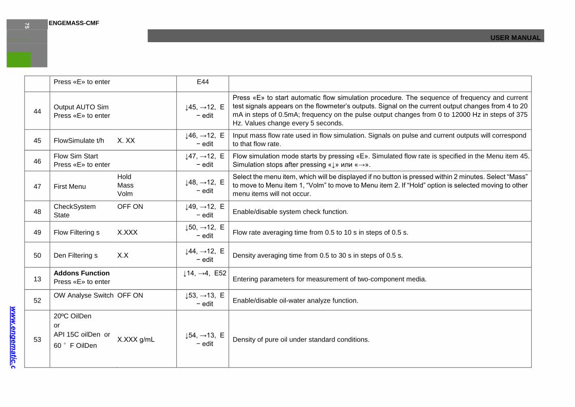
ENGEMASS-CMF
USER MANUAL
Press «E» to enter E44
44 Output AUTO Sim
Press «E» to enter
↓45, →12, Е
− edit
Press «Е» to start automatic flow simulation procedure. The sequence of frequency and current
test signals appears on the flowmeter’s outputs. Signal on the current output changes from 4 to 20
mA in steps of 0.5mA; frequency on the pulse output changes from 0 to 12000 Hz in steps of 375
Hz. Values change every 5 seconds.
45 FlowSimulate t/h Х. ХХ ↓46, →12, Е
− edit
Input mass flow rate used in flow simulation. Signals on pulse and current outputs will correspond
to that flow rate.
46 Flow Sim Start
Press «E» to enter
↓47, →12, Е
− edit
Flow simulation mode starts by pressing «Е». Simulated flow rate is specified in the Menu item 45.
Simulation stops after pressing «↓» или «→».
47 First Menu
Hold
Mass
Volm
↓48, →12, Е
− edit
Select the menu item, which will be displayed if no button is pressed within 2 minutes. Select “Mass”
to move to Menu item 1, “Volm” to move to Menu item 2. If “Hold” option is selected moving to other
menu items will not occur.
48 CheckSystem
State
OFF ON ↓49, →12, Е
− edit Enable/disable system check function.
49 Flow Filtering s Х.ХХХ ↓50, →12, Е
− edit Flow rate averaging time from 0.5 to 10 s in steps of 0.5 s.
50 Den Filtering s Х.Х ↓44, →12, Е
− edit Density averaging time from 0.5 to 30 s in steps of 0.5 s.
13 Addons Function
Press «E» to enter
↓14, →4, Е52 Entering parameters for measurement of two-component media.
52 OW Analyse Switch OFF ON ↓53, →13, Е
− edit Enable/disable oil-water analyze function.
53
20ºC OilDen
or
API 15C oilDen or
60 °F OilDen
Х.ХХХ g/mL ↓54, →13, Е
− edit Density of pure oil under standard conditions.
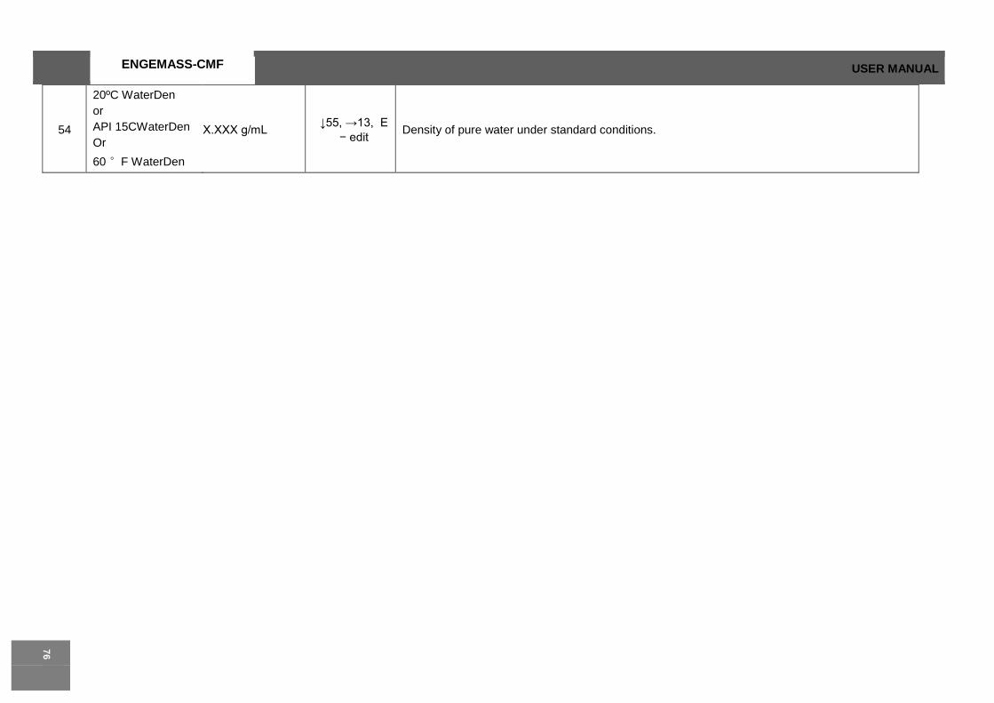
ENGEMASS-CMF USER MANUAL
54
20ºC WaterDen
or
API 15CWaterDen
Or
60 °F WaterDen
Х.ХХХ g/mL ↓55, →13, Е
− edit Density of pure water under standard conditions.

ENGEMASS-CMF
USER MANUAL

ENGEMASS-CMF USER MANUAL
55 GasContainCorre Х.ХХХ ↓56, →13,
Е – edit
Flow compensation by percentage of gas in the oil-water. It works only if oil-water analyze function
is enabled in the Menu item 52.
56 WContainCorre Х.ХХХ ↓57, →13,
Е – edit
Flow compensation by percentage of pure water in the oil-water (not realized in current versions of
flowmeters).
57 Density Range OFF
ON
↓58, →13,
Е – edit
Enable/disable density range check. When enabled and If density of the medium is out of range
specified in menu items 58 and 59 then the volumetric flow will not be calculated.
58 UpperDen Х.ХХХХ ↓59, →13, Е
– edit The upper limit of density range (see Menu item 57).
59 LowerDen Х.ХХХХ ↓52, →13,
Е – edit The lower limit of density range (see Menu item 57).
14 Change Password
Press «E» to enter
↓8, →4, Е87 Password changing is used for protection against unauthorized access to the settings of the
flowmeter.
87 EnterOld PassWord
000000 ↓→ edit,
Е88 Input current password If the entered password is invalid a message “Wrong password” will
be displayed. To return to the Menu item 14 “Change Password”
press «→». To enter the password again press «↓».
88 EnterNew
PassWord 000000 ↓→ edit,
Е89 Input new password
89 NewPassWord
Again 000000 ↓→ edit,
Е90 Confirm new password
90 PWD Succeed NewPWD 000000 ↓14, →14, Е14
New password is displayed
5 Calibration
Press «E» to enter
↓6, →1,
Е60 Setting of calibration parameters provided for measuring flow, density, temperature.
60 FlowCal Х.ХХХ g/s/us ↓61, →5, Е
− edit Calibration coefficient K.
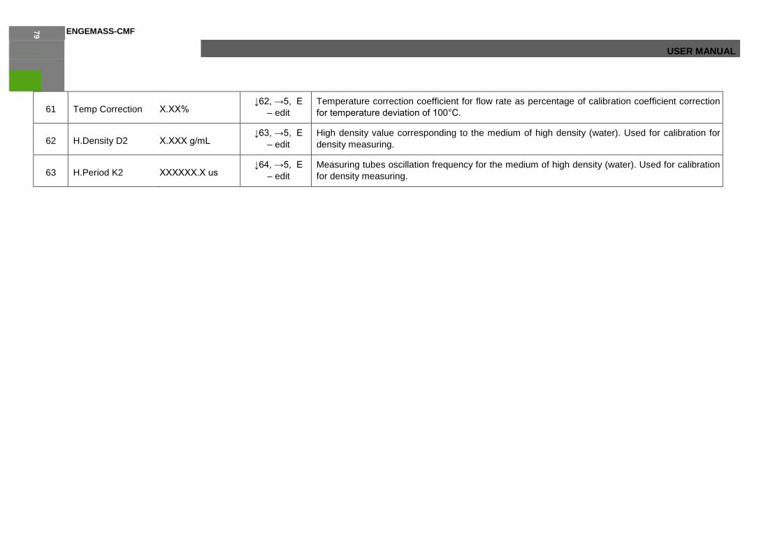
ENGEMASS-CMF
USER MANUAL
61 Temp Correction Х.ХХ% ↓62, →5, Е
– edit
Temperature correction coefficient for flow rate as percentage of calibration coefficient correction
for temperature deviation of 100°С.
62 H.Density D2 Х.ХХХ g/mL ↓63, →5, Е
– edit
High density value corresponding to the medium of high density (water). Used for calibration for
density measuring.
63 H.Period K2 ХХХХХХ.Х us ↓64, →5, Е
– edit
Measuring tubes oscillation frequency for the medium of high density (water). Used for calibration
for density measuring.

ENGEMASS-CMF USER MANUAL
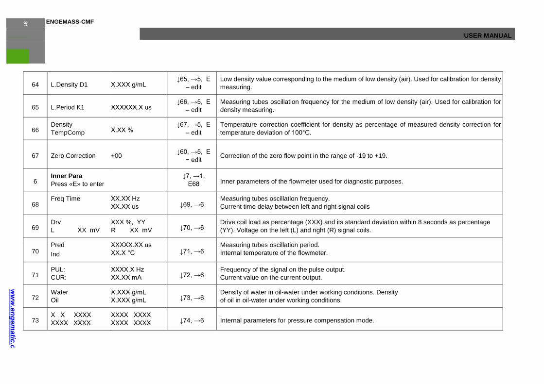
ENGEMASS-CMF
USER MANUAL
64 L.Density D1 Х.ХХХ g/mL ↓65, →5, Е
– edit
Low density value corresponding to the medium of low density (air). Used for calibration for density
measuring.
65 L.Period K1 ХХХХХХ.Х us ↓66, →5, Е
– edit
Measuring tubes oscillation frequency for the medium of low density (air). Used for calibration for
density measuring.
66 Density
TempComp Х.ХХ % ↓67, →5, Е
– edit
Temperature correction coefficient for density as percentage of measured density correction for
temperature deviation of 100°С.
67 Zero Correction +00 ↓60, →5, Е
− edit Correction of the zero flow point in the range of -19 to +19.
6 Inner Para
Press «E» to enter
↓7, →1,
Е68 Inner parameters of the flowmeter used for diagnostic purposes.
68 Freq Time ХХ.ХХ Hz
ХХ.ХХ us ↓69, →6 Measuring tubes oscillation frequency.
Current time delay between left and right signal coils
69 Drv
L XX mV
XXX %, YY
R XX mV ↓70, →6 Drive coil load as percentage (XXX) and its standard deviation within 8 seconds as percentage
(YY). Voltage on the left (L) and right (R) signal coils.
70 Pred
Ind
ХХХXX.ХХ us
ХХ.Х °С ↓71, →6 Measuring tubes oscillation period.
Internal temperature of the flowmeter.
71 PUL:
CUR:
ХХХХ.Х Hz
ХХ.ХХ mA ↓72, →6 Frequency of the signal on the pulse output.
Current value on the current output.
72 Water
Oil
Х.ХХХ g/mL
Х.ХХХ g/mL ↓73, →6 Density of water in oil-water under working conditions. Density
of oil in oil-water under working conditions.
73 Х Х ХХХХ
ХХХХ ХХХХ
ХХХХ ХХХХ
ХХХХ ХХХХ ↓74, →6 Internal parameters for pressure compensation mode.
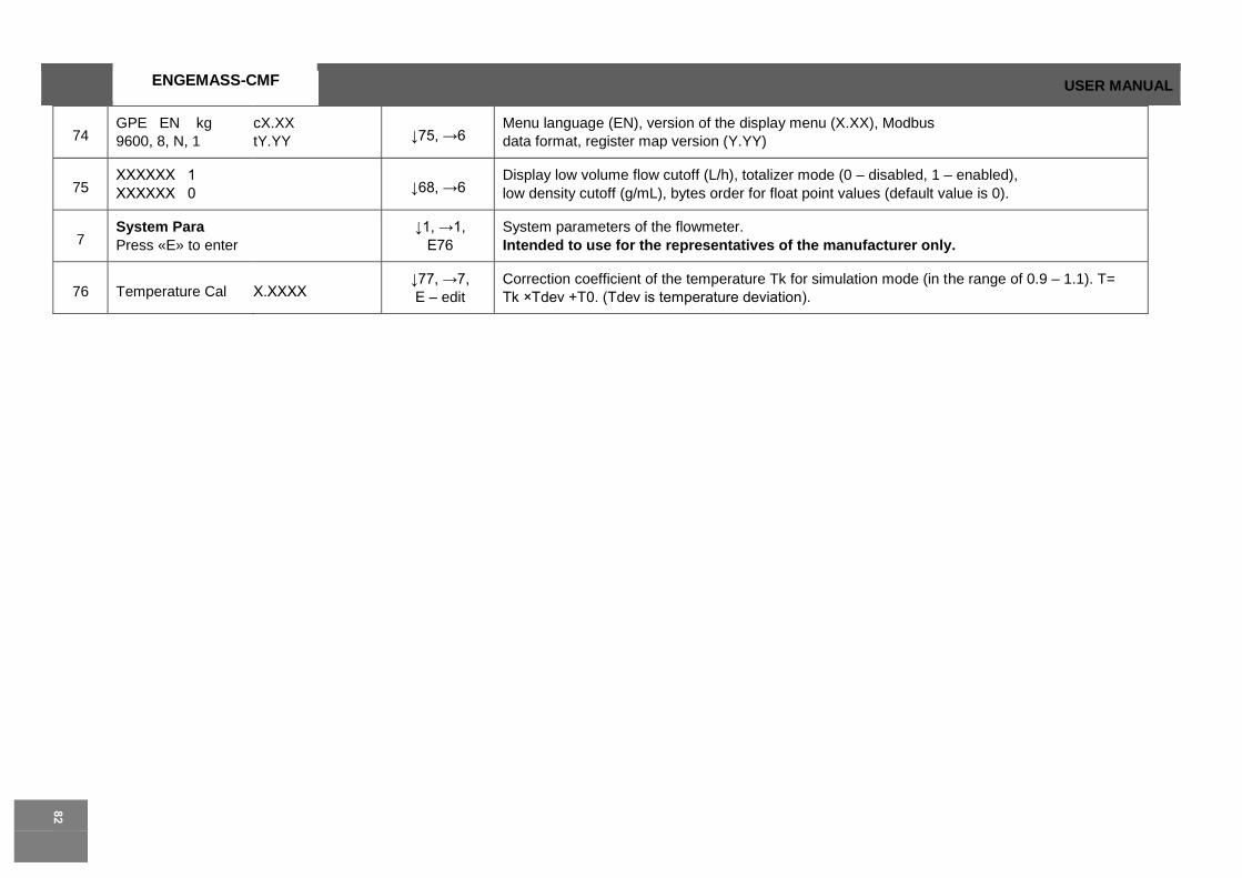
ENGEMASS-CMF USER MANUAL
74 GPE EN kg
9600, 8, N, 1
cX.XX
tY.YY ↓75, →6 Menu language (EN), version of the display menu (X.XX), Modbus
data format, register map version (Y.YY)
75 ХХХХХХ 1
ХХХХХХ 0 ↓68, →6 Display low volume flow cutoff (L/h), totalizer mode (0 – disabled, 1 – enabled),
low density cutoff (g/mL), bytes order for float point values (default value is 0).
7 System Para
Press «E» to enter
↓1, →1,
Е76
System parameters of the flowmeter.
Intended to use for the representatives of the manufacturer only.
76 Temperature Cal Х.ХХХХ ↓77, →7,
Е – edit
Correction coefficient of the temperature Tk for simulation mode (in the range of 0.9 – 1.1). T=
Tk ×Tdev +Т0. (Tdev is temperature deviation).

ENGEMASS-CMF
USER MANUAL
77 Temperature Zero Х.ХХ ↓78, →7, Е
– edit Zero temperature T0 for simulation mode (in the range of -20С° to +20С°).
78 DensityCal Х.ХХХХ ↓79, →7, Е
– edit
Correction coefficient of the density ρk for simulation mode (in the range of 0.9 – 1.1).
ρ= ρk× ρdev + ρ0. (ρdev is density deviation).
79 DensityZero Х.ХХ ↓80, →7, Е
– edit 3 3
Zero density ρ0 for simulation mode (in the range of -0.1 g/cm to +0.1 g/cm ).
80 Menu Language RUS
ENG
↓81, →7, Е
– edit Select display menu language. Switching from English language to Russia
81 MultipointCorrect OFF
ON
↓82, →7, Е
– edit
Enable/disable multipoint correction function used for correction of the calibration coefficient in
several points of flow rate (time delay).
82 Restore Para
Press «E» to enter
↓83, →7, Е
– edit
Restore of all coefficients and settings of the flowmeter, except for calibration parameters in the
menu items 60-67, to factory defaults.
83 Correction Point Х ↓84, →7, Е
– edit Number of correction coefficient (0 – 7), which values are specified in the menu items 84 and 85.
84 No X TimeValue YY.YYY ↓85, →7, Е
– edit
The value of time delay between left and right signal coils (YY.YYY µs) for the correction coefficient
number X.
85 No XCorrectValue ХХ.ХХХ ↓76, →7, Е
− edit
Correction coefficient (in the range of 0.9 to 1.1) applied to the calibration coefficient K for time delay
point specified in the menu item 84.
84 84
2.5.4 Zero point After installation and Power wiring, a zero point adjustment (zero calibration) adjustment
procedure should be performed. This procedure sets the base point corresponding to zero flow. Without actual
flow there is a certain time delay between signal coils anyway, that delay assumed as zero point. To perform this
procedure, follow these steps:
• Apply power to the flowmeter and let it warm up for at least 30
minutes;
• Let the measuring medium flow through the flowmeter, as long
as the thermal balance is established;
• Close the valve located after the flowmeter;
• Make sure that the flowmeter’s tubes are completely filled with
fluid;
• Close the valve located before the flowmeter(see Fig. 2.16);
• Make sure that the fluid in the flowmeter is completely still;
USER MANUAL

ENGEMASS-CMF
59
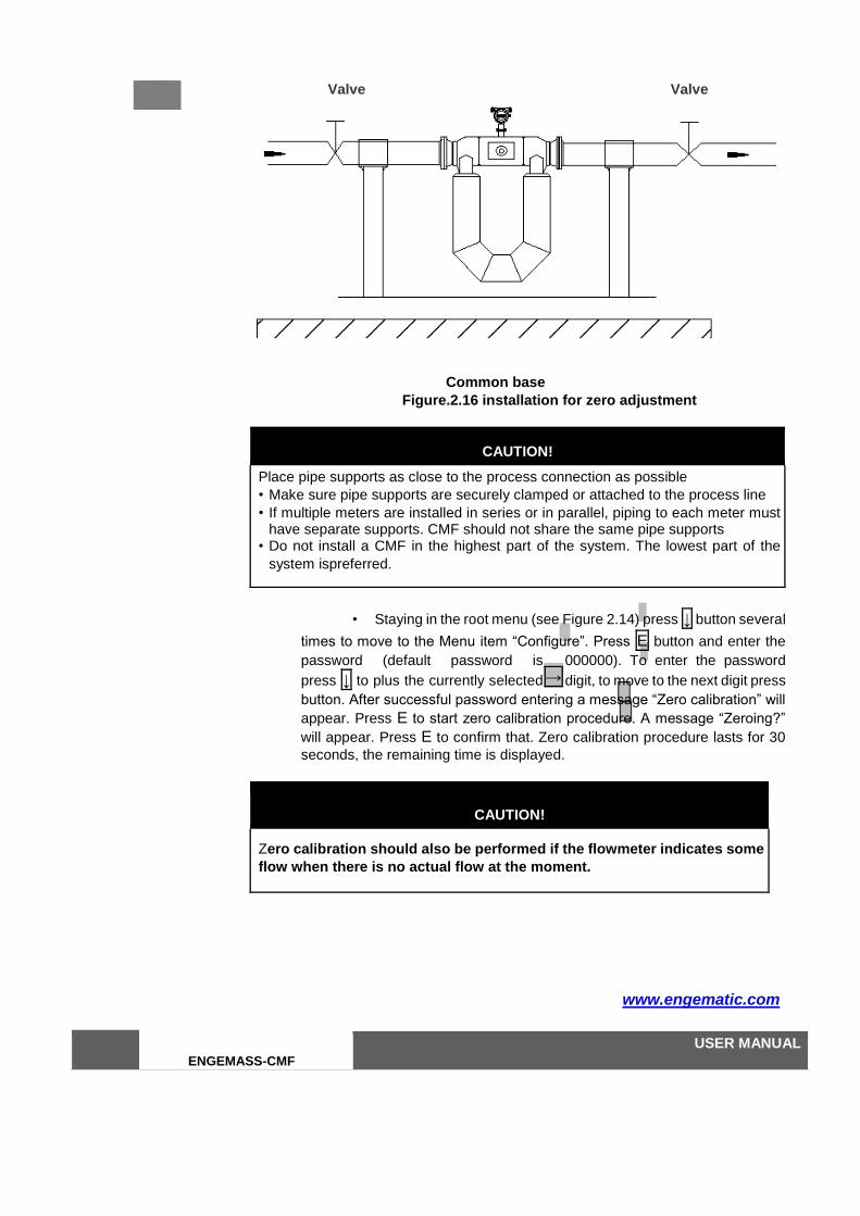
86 86
Valve Valve
Common base
Figure.2.16 installation for zero adjustment
CAUTION!
Place pipe supports as close to the process connection as possible
• Make sure pipe supports are securely clamped or attached to the process line
• If multiple meters are installed in series or in parallel, piping to each meter must have separate supports. CMF should not share the same pipe supports
• Do not install a CMF in the highest part of the system. The lowest part of the
system ispreferred.
• Staying in the root menu (see Figure 2.14) press ↓ button several
times to move to the Menu item “Configure”. Press E button and enter the
password (default password is 000000). To enter the password
press ↓ to plus the currently selected digit, to move to the next digit press
button. After successful password entering a message “Zero calibration” will
appear. Press E to start zero calibration procedure. A message “Zeroing?”
will appear. Press E to confirm that. Zero calibration procedure lasts for 30
seconds, the remaining time is displayed.
CAUTION!
Zero calibration should also be performed if the flowmeter indicates some
flow when there is no actual flow at the moment.
www.engematic.com
ENGEMASS-CMF
USER MANUAL
→
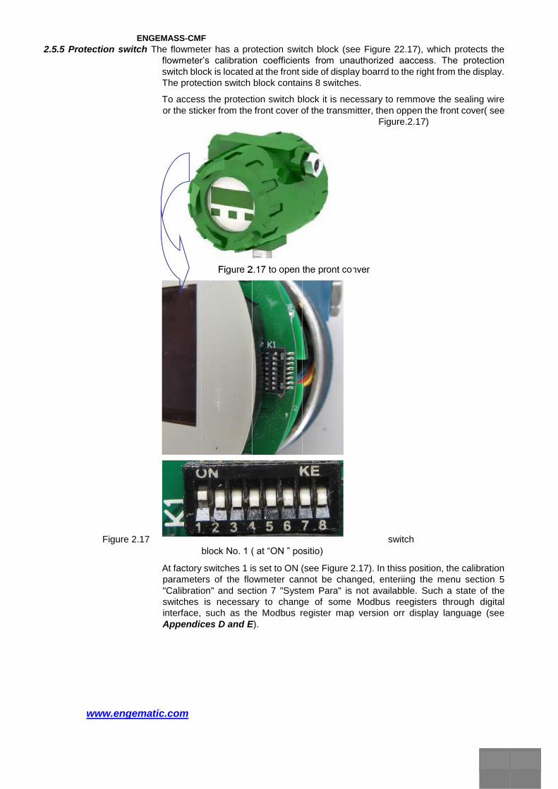
ENGEMASS-CMF
2.5.5 Protection switch The flowmeter has a protection switch block (see Figure 22.17), which protects the
flowmeter’s calibration coefficients from unauthorized aaccess. The protection
switch block is located at the front side of display boarrd to the right from the display.
The protection switch block contains 8 switches.
To access the protection switch block it is necessary to remmove the sealing wire
or the sticker from the front cover of the transmitter, then oppen the front cover( see
Figure.2.17)
Figure 2.17 switch
block No. 1 ( at “ON ” positio)
At factory switches 1 is set to ON (see Figure 2.17). In thiss position, the calibration
parameters of the flowmeter cannot be changed, enteriing the menu section 5
"Calibration" and section 7 "System Para" is not availabble. Such a state of the
switches is necessary to change of some Modbus reegisters through digital
interface, such as the Modbus register map version orr display language (see
Appendices D and E).
www.engematic.com
88 88
If any of switches 1-8 is set to ON, the entrance to the "CCalibration" and "System
Para" sections will also be impossible. But you still can vieww the values.
To enter the "Calibration" and "System Para" sections andd change or just see the
calibration coefficients, it is necessary to set all the swwitches to OFF positions
(see Figure 2.18).

ENGEMASS-CMF
6 1
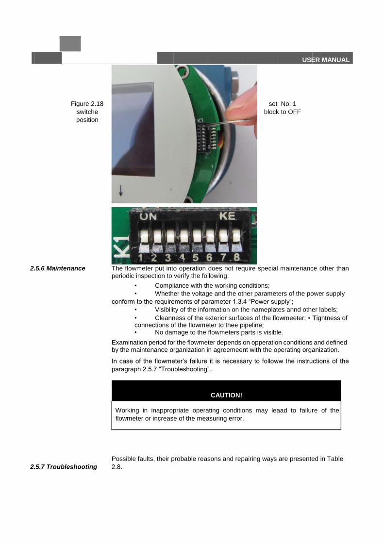
90 90
Figure 2.18 set No. 1
switche block to OFF
position
2.5.6 Maintenance The flowmeter put into operation does not require special maintenance other than periodic inspection to verify the following:
• Compliance with the working conditions;
• Whether the voltage and the other parameters of the power supply
conform to the requirements of parameter 1.3.4 “Power supply”;
• Visibility of the information on the nameplates annd other labels;
• Cleanness of the exterior surfaces of the flowmeeter; • Tightness of connections of the flowmeter to thee pipeline; • No damage to the flowmeters parts is visible.
Examination period for the flowmeter depends on opperation conditions and defined by the maintenance organization in agreemeent with the operating organization.
In case of the flowmeter’s failure it is necessary to followw the instructions of the
paragraph 2.5.7 “Troubleshooting”.
CAUTION!
Working in inappropriate operating conditions may leaad to failure of the
flowmeter or increase of the measuring error.
2.5.7 Troubleshooting
Possible faults, their probable reasons and repairing ways are presented in Table
2.8.
US E R MANUA L

ENGEMASS-CMF
www.engematic.com
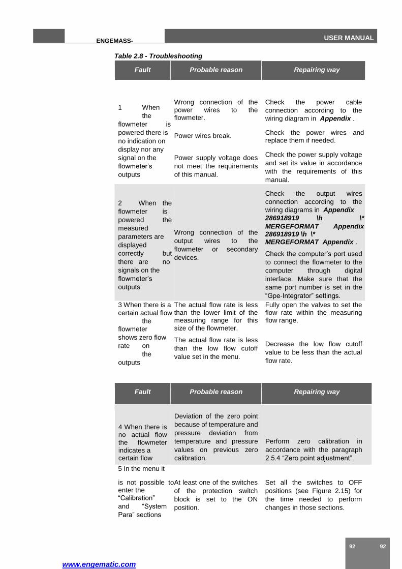
www.engematic.com
92 92
ENGEMASS-
CMF
USER MANUAL
Table 2.8 - Troubleshooting
Fault Probable reason Repairing way
1 When
the
flowmeter is
powered there is
no indication on
display nor any
signal on the
flowmeter’s
outputs
Wrong connection of the power wires to the flowmeter.
Power wires break.
Power supply voltage does
not meet the requirements
of this manual.
Check the power cable
connection according to the
wiring diagram in Appendix .
Check the power wires and replace them if needed.
Check the power supply voltage
and set its value in accordance
with the requirements of this
manual.
2 When the
flowmeter is
powered the
measured
parameters are
displayed
correctly but
there are no
signals on the
flowmeter’s
outputs
Wrong connection of the
output wires to the
flowmeter or secondary
devices.
Check the output wires
connection according to the
wiring diagrams in Appendix
286918919 \h \*
MERGEFORMAT Appendix 286918919 \h \* MERGEFORMAT Appendix .
Check the computer’s port used
to connect the flowmeter to the
computer through digital
interface. Make sure that the
same port number is set in the
“Gpe-Integrator” settings.
3 When there is a
certain actual flow
the
flowmeter
shows zero flow
rate on
the
outputs
The actual flow rate is less than the lower limit of the measuring range for this size of the flowmeter.
The actual flow rate is less
than the low flow cutoff
value set in the menu.
Fully open the valves to set the flow rate within the measuring flow range.
Decrease the low flow cutoff
value to be less than the actual
flow rate.
Fault Probable reason Repairing way
4 When there is no actual flow the flowmeter indicates a certain flow
Deviation of the zero point
because of temperature and
pressure deviation from
temperature and pressure
values on previous zero
calibration.
Perform zero calibration in
accordance with the paragraph
2.5.4 “Zero point adjustment”.
5 In the menu it
is not possible to enter the “Calibration”
and “System
Para” sections
At least one of the switches
of the protection switch
block is set to the ON
position.
Set all the switches to OFF
positions (see Figure 2.15) for
the time needed to perform
changes in those sections.
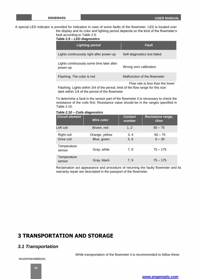
www.engematic.com
93
ENGEMASS-
CMF USER MANUAL
A special LED indicator is provided for indication in case of some faults of the flowmeter. LED is located over
the display and its color and lighting period depends on the kind of the flowmeter’s
fault according to Table 2.9.
Table 2.9 – LED diagnostics
Lighting period Fault
Lights continuously right after power-up Self-diagnostics test failed
Lights continuously some time later after
power-up Wrong zero calibration
Flashing. The color is red Malfunction of the flowmeter
Flow rate is less than the lower
Flashing. Lights within 3/4 of the period, limit of the flow range for this size
dark within 1/4 of the period of the flowmeter
To determine a fault in the sensor part of the flowmeter it is necessary to check the
resistance of the coils first. Resistance value should be in the ranges specified in
Table 2.10.
Table 2.10 – Coils diagnostics
Circuit element Wire color
Contact
number
Resistance range,
Ohm
Left coil Brown, red 1, 2 60 – 75
Right coil Orange, yellow 3, 4 60 – 75
Drive coil Blue, green 5, 6 6 – 30
Temperature
sensor Gray, white 7, 8 75 – 175
Temperature
sensor Gray, black 7, 9 75 – 175
Reclamation act appearance and procedure of returning the faulty flowmeter and its
warranty repair are descripted in the passport of the flowmeter.
3 TRANSPORTATION AND STORAGE
3.1 Transportation
While transportation of the flowmeter it is recommended to follow these
recommendations:
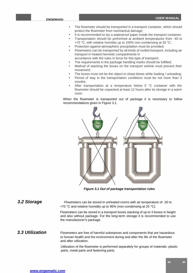
www.engematic.com
94 94
ENGEMASS-
CMF
USER MANUAL
• The flowmeter should be transported in a transport container, which should
protect the flowmeter from mechanical damage;
• It is recommended to lay a waterproof paper inside the transport container;
• Transportation should be performed at ambient temperatures from -40 to
+70 °C, with relative humidity up to 100% non-condensing at 35 °C;
• Protection against atmospheric precipitation must be provided;
• Flowmeters can be transported by all kinds of roofed transport, including air
transport in heated hermetic compartments in
accordance with the rules in force for this type of transport;
• The requirements in the package handling marks should be fulfilled;
• Method of stacking the boxes on the transport vehicle must prevent their
movement;
• The boxes must not be the object to sharp blows while loading / unloading;
• Period of stay in the transportation conditions must be not more than 3
months;
• After transportation at a temperature below 0 °C container with the
flowmeter should be unpacked at least 12 hours after its storage in a warm
room.
When the flowmeter is transported out of package it is necessary to follow
recommendations given in Figure 3.1.
Figure 3.1 Out of package transportation rules
3.2 Storage Flowmeters can be stored in unheated rooms with air temperature of -20 to
+70 °C and relative humidity up to 95% (non-condensing at 25 °C).
Flowmeters can be stored in a transport boxes stacking of up to 3 boxes in height
and also without package. For the long-term storage it is recommended to use
the manufacturer's package.
3.3 Utilization Flowmeters are free of harmful substances and components that are hazardous
to human health and the environment during and after the life of the flowmeter
and after utilization.
Utilization of the flowmeter is performed separately for groups of materials: plastic
parts, metal parts and fastening parts.
www.engematic.com
95
ENGEMASS-
CMF USER MANUAL
4 Verification
Verification of the flowmeters is performed in accordance with the document
"Instructions GSI. ENGEMASS-Series Coriolis Mass Flowmeter. Verification
procedure."

www.engematic.com
96 96
ENGEMASS-
CMF
USER MANUAL
Appendix A
Outline dimensions and weight
Figure A.1 Outline dimensions( T and U type sensor)
Integral type – Figure A.1.1., A.1.2
Separate type – Figure A.1.3, A.1.4
Table A.1 – Outline dimensions and weight
Figure L, mm L1, H, mm H1, mm H2, mm Weight, kg
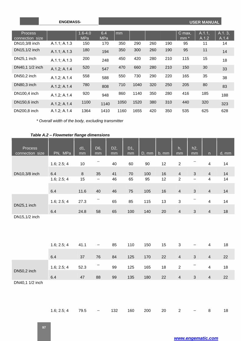
www.engematic.com
97
ENGEMASS-
CMF USER MANUAL
Process
connection size
1.6-4.0
MPa
6.4
MPa
mm С max,
mm *
А.1.1,
А.1.2
А.1. 3,
А.1.4
DN10,3/8 inch А.1.1; А.1.3 150 170 350 290 260 190 95 11 14
DN15,1/2 inch А.1.1; А.1.3 180 194 350 300 260 190 95 11 14
DN25,1 inch А.1.1; А.1.3 200 248 450 420 280 210 115 15 18
DN40,1 1/2 inch А.1.2; А.1.4 520 547 470 660 280 210 150 30 33
DN50,2 inch А.1.2; А.1.4 558 588 550 730 290 220 165 35 38
DN80,3 inch А.1.2; А.1.4 780 808 710 1040 320 250 205 80 83
DN100,4 inch А.1.2; А.1.4 920 948 860 1140 350 280 416 185 188
DN150,6 inch А.1.2; А.1.4 1100 1140 1050 1520 380 310 440 320 323
DN200,8 inch А.1.2; А.1.4 1364 1410 1160 1655 420 350 535 625 628
* Overall width of the body, excluding transmitter
Table A.2 – Flowmeter flange dimensions
Process
connection size PN, MPa
d1,
mm
D6,
mm
D2,
mm
D1,
mm D, mm b, mm
h,
mm
h2,
mm n d, mm
DN10,3/8 inch
1.6; 2.5; 4 10
40 60 90 12 2
4 14
6.4 8 35 41 70 100 16 4 3 4 14
1.6; 2.5; 4 15 46 65 95 12 2 4 14
DN15,1/2 inch
1.6; 2.5; 4 41.1 85 110 150 15 3 4 18
DN40,1 1/2 inch
1.6; 2.5; 4 79.5 132 160 200 20 2 8 18
6.4 11.6 40 46 75 105 16 4 3 4 14
DN25,1 inch 1.6; 2.5; 4 27.3
65 85 115 13 3
4 14
6.4 24.8 58 65 100 140 20 4 3 4 18
6.4 37 76 84 125 170 22 4 3 4 22
DN50,2 inch 1.6; 2.5; 4 52.3
99 125 165 18 2
4 18
6.4 47 88 99 135 180 22 4 3 4 22

www.engematic.com
98 98
ENGEMASS-
CMF
USER MANUAL
DN80,3 inch
1.6; 2.5; 4 154 211 250 300 26 2 8 26
DN150,6 inch
L
L
6.4 77 121 132 170 215 24 4 3 8 22
DN100,4 inch 1.6; 2.5; 4 101.7
156 190 235 21 3
8 22
6.4 94 150 156 200 250 25.5 4.5 3.5 8 26
6.4 142 204 211 280 345 31.5 4.5 3.5 8 33
DN200,8 inch 1.6; 2.5; 4 200
285 320 375 35 3
12 30
6.4 198 260 284 345 415 37.5 4.5 3.5 12 36

www.engematic.com
99
ENGEMASS-
CMF USER MANUAL
L1 L1
A.2.1 A.2.2
Figure A.2 Outline dimensions( M type sensor)
Integral type – Figure A.2.1
Separate type – Figure A.2.2
Table A.3 – Outline dimensions and weight
Process
connection size Figure
L, mm L1,
mm
H,
mm
H1,
mm
H2,
mm
С max,
mm *
Weight, kg
1.6-4.0
MPa
6.4
MPa
A.2.1
A.2.2
DN10,3/8 inch A.2 360 374 240 180 290 220 95 10 13
DN15,1/2 inch A.2 400 414 280 184 290 220 115 11 14
DN25,1 inch A.2 500 536 360 250 300 230 150 15 18
DN40,1 1/2 inch A.2 600 634 460 300 310 240 165 30 33
DN50,2 inch A.2 800 828 640 410 320 250 205 35 38
DN80,3 inch A.2 900 928 700 490 350 280 416 75 78
DN100,4 inch A.2 1130 1156 860 660 370 290 440 132 135
DN150,6 inch A.2 1410 1450 1200 900 400 330 535 263 265
DN200,8 inch A2 1800
1844 1450 1170 420 350 580 427
430
* Overall width of the body, excluding transmitter
Figure A.3 Outline dimensions ( S type sensor)
Table A.4 – Outline dimensions and weight
Process
connection size Figure
L, mm L1,
mm
H,
mm
H1,
mm
С max,
mm *
Weight, kg
1.6-4.0
MPa
6.4
MPa А.3
DN50,2 inch А.3 800 834 620 200 320 205 30
DN80,3 inch А.3 935 973 730 200 350 416 60
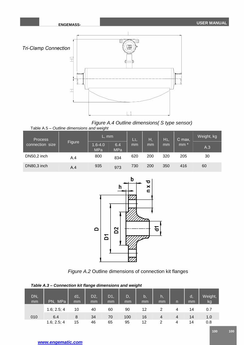
www.engematic.com
100 100
ENGEMASS-
CMF
USER MANUAL
Figure A.4 Outline dimensions( S type sensor) Table A.5 – Outline dimensions and weight
Process
connection size Figure
L, mm L1,
mm
H,
mm
H1,
mm
С max,
mm *
Weight, kg
1.6-4.0
MPa
6.4
MPa А.3
DN50,2 inch А.4 800 834 620 200 320 205 30
DN80,3 inch А.4 935 973 730 200 350 416 60
Figure A.2 Outline dimensions of connection kit flanges
Table A.3 – Connection kit flange dimensions and weight
DN,
mm PN, MPa
d1,
mm
D2,
mm
D1,
mm
D,
mm
b,
mm
h,
mm n
d,
mm
Weight,
kg
010
1.6; 2.5; 4 10 40 60 90 12 2 4 14 0.7
6.4 8 34 70 100 16 4 4 14 1.0
1.6; 2.5; 4 15 46 65 95 12 2 4 14 0.8
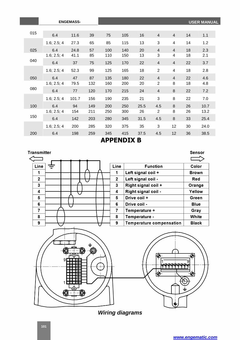
www.engematic.com
101
ENGEMASS-
CMF USER MANUAL
015 6.4 11.6 39 75 105 16 4 4 14 1.1
025
1.6; 2.5; 4 27.3 65 85 115 13 3 4 14 1.2
6.4 24.8 57 100 140 20 4 4 18 2.3
1.6; 2.5; 4 41.1 85 110 150 13 3 4 18 2.1
040 6.4 37 75 125 170 22 4 4 22 3.7
050
1.6; 2.5; 4 52.3 99 125 165 18 2 4 18 2.8
6.4 47 87 135 180 22 4 4 22 4.6
1.6; 2.5; 4 79.5 132 160 200 20 2 8 18 4.8
080 6.4 77 120 170 215 24 4 8 22 7.2
100
1.6; 2.5; 4 101.7 156 190 235 21 3 8 22 7.0
6.4 94 149 200 250 25.5 4.5 8 26 10.7
1.6; 2.5; 4 154 211 250 300 26 2 8 26 13.2
150 6.4 142 203 280 345 31.5 4.5 8 33 25.4
200
1.6; 2.5; 4 200 285 320 375 35 3 12 30 24.0
6.4 198 259 345 415 37.5 4.5 12 36 38.5
APPENDIX B
Wiring diagrams
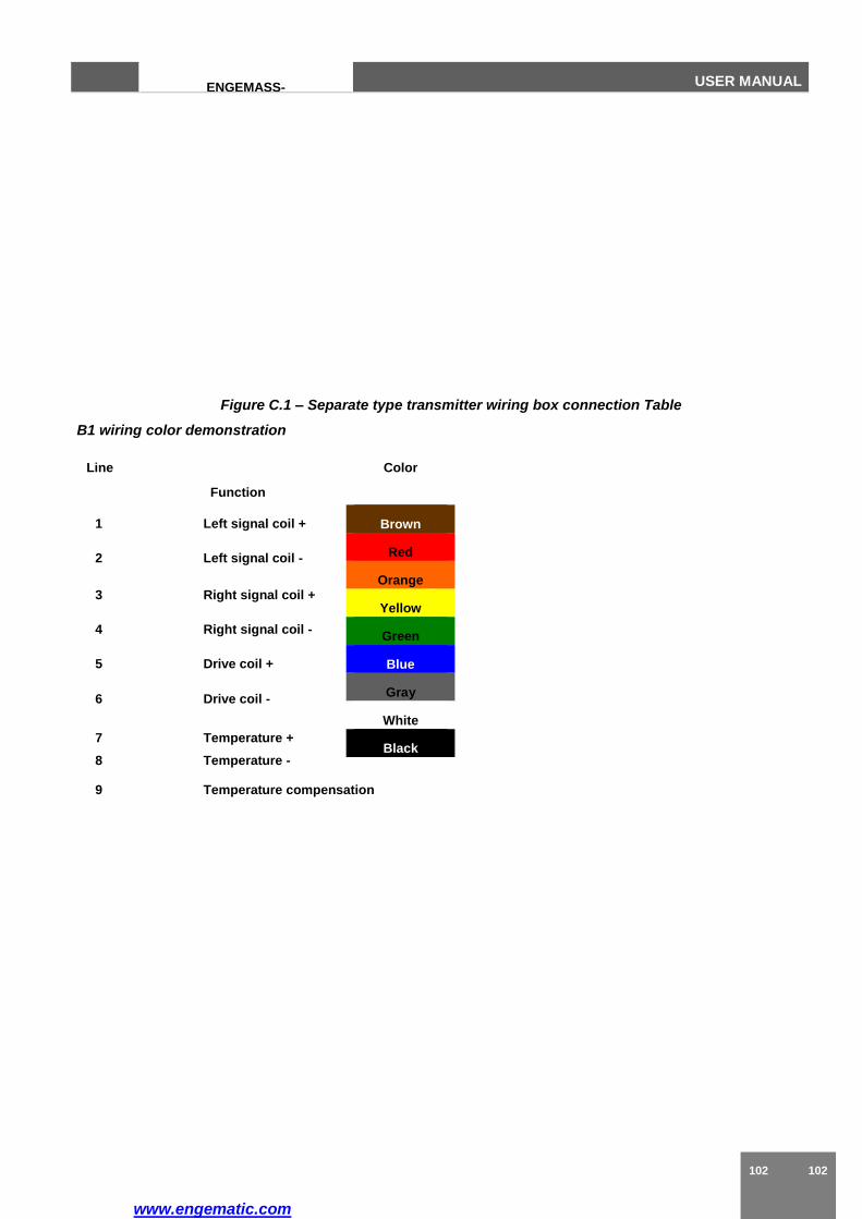
www.engematic.com
102 102
ENGEMASS-
CMF
USER MANUAL
Figure C.1 – Separate type transmitter wiring box connection Table
B1 wiring color demonstration
Line Color
Function
1 Left signal coil +
2 Left signal coil -
3 Right signal coil +
4 Right signal coil -
5 Drive coil +
6 Drive coil -
7 Temperature +
8 Temperature -
9 Temperature compensation
Brown
Red
Orange
Yellow
Green
Blue
Gray
White
Black

www.engematic.com
103
ENGEMASS-
CMF USER MANUAL
Output Signal Power Supply
Figure C.2 – Power supply connection
Figure C.3 – Pulse output connection
Output Signal Power Supply

www.engematic.com
104 104
ENGEMASS-
CMF
USER MANUAL
Figure C.4 – Current and hart communication output connection
Figure C.5 – Digital utput connection
Output Signal Power Supply
Output Signal Power Supply
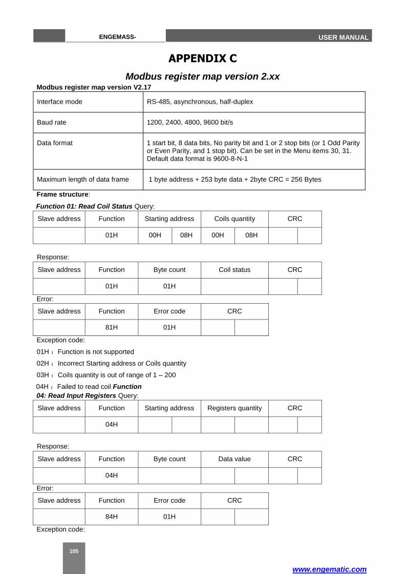
www.engematic.com
105
ENGEMASS-
CMF USER MANUAL
APPENDIX C
Modbus register map version 2.xx Modbus register map version V2.17
Interface mode RS-485, asynchronous, half-duplex
Baud rate 1200, 2400, 4800, 9600 bit/s
Data format 1 start bit, 8 data bits, No parity bit and 1 or 2 stop bits (or 1 Odd Parity or Even Parity, and 1 stop bit). Can be set in the Menu items 30, 31. Default data format is 9600-8-N-1
Maximum length of data frame 1 byte address + 253 byte data + 2byte CRC = 256 Bytes
Frame structure:
Function 01: Read Coil Status Query:
Slave address Function Starting address Coils quantity CRC
01H 00H 08H 00H 08H
Response:
Slave address Function Byte count Coil status CRC
01H 01H
Error:
Slave address Function Error code CRC
81H 01H
Exception code:
01H :Function is not supported
02H :Incorrect Starting address or Coils quantity
03H :Coils quantity is out of range of 1 – 200
04H :Failed to read coil Function
04: Read Input Registers Query:
Slave address Function Starting address Registers quantity CRC
04H
Response:
Slave address Function Byte count Data value CRC
04H
Error:
Slave address Function Error code CRC
84H 01H
Exception code:
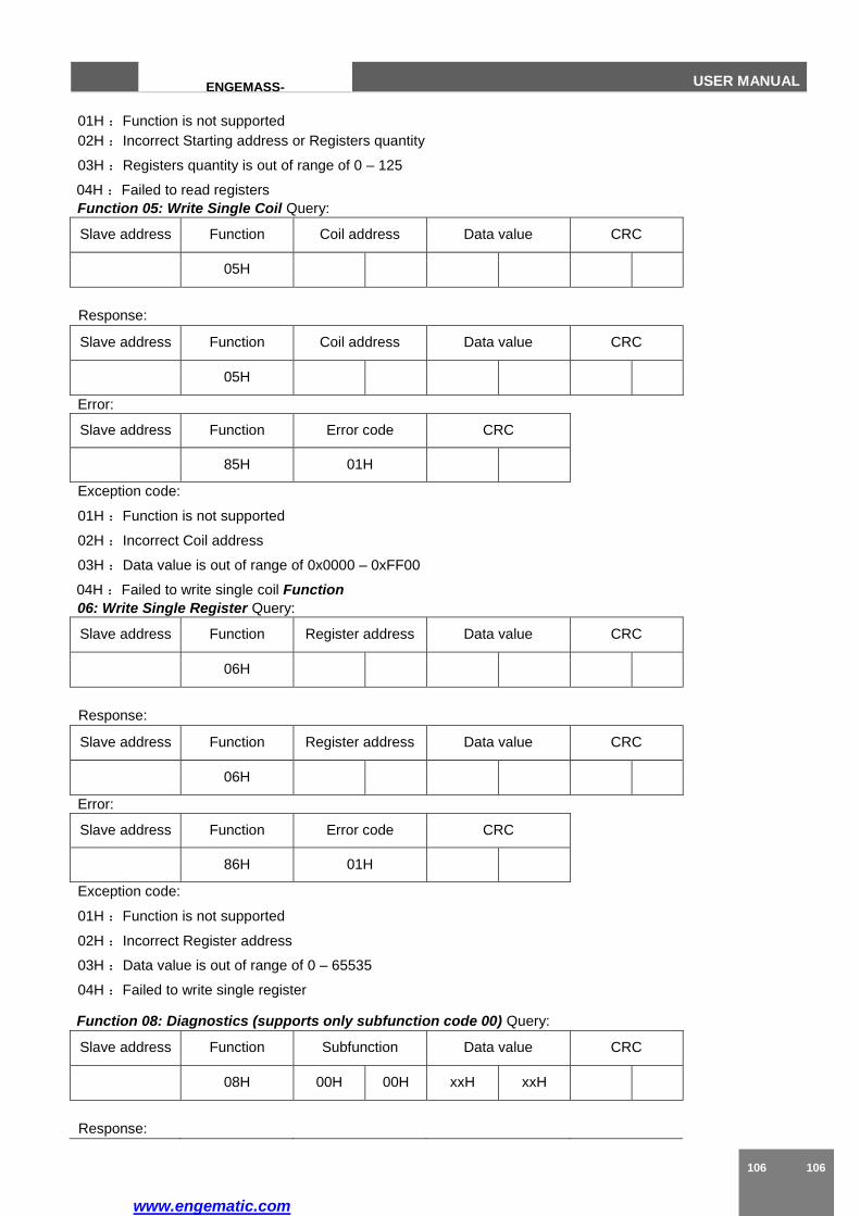
www.engematic.com
106 106
ENGEMASS-
CMF
USER MANUAL
01H :Function is not supported
02H :Incorrect Starting address or Registers quantity
03H :Registers quantity is out of range of 0 – 125
04H :Failed to read registers
Function 05: Write Single Coil Query:
Slave address Function Coil address Data value CRC
05H
Response:
Slave address Function Coil address Data value CRC
05H
Error:
Slave address Function Error code CRC
85H 01H
Exception code:
01H :Function is not supported
02H :Incorrect Coil address
03H :Data value is out of range of 0x0000 – 0xFF00
04H :Failed to write single coil Function
06: Write Single Register Query:
Slave address Function Register address Data value CRC
06H
Response:
Slave address Function Register address Data value CRC
06H
Error:
Slave address Function Error code CRC
86H 01H
Exception code:
01H :Function is not supported
02H :Incorrect Register address
03H :Data value is out of range of 0 – 65535
04H :Failed to write single register
Function 08: Diagnostics (supports only subfunction code 00) Query:
Slave address Function Subfunction Data value CRC
08H 00H 00H xxH xxH
Response:
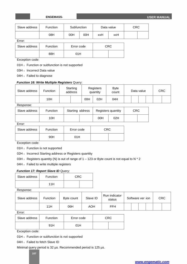
www.engematic.com
107
ENGEMASS-
CMF USER MANUAL
Slave address Function Subfunction Data value CRC
08H 00H 00H xxH xxH
Error:
Slave address Function Error code CRC
88H 01H
Exception code:
01H :Function or subfunction is not supported
03H :Incorrect Data value
04H :Failed to diagnose
Function 16: Write Multiple Registers Query:
Slave address Function Starting
address
Registers
quantity
Byte
count Data value
CRC
10H 00H 02H 04H
Response:
Slave address Function Starting address Registers quantity CRC
10H 00H 02H
Error:
Slave address Function Error code CRC
90H 01H
Exception code:
01H :Function is not supported
02H :Incorrect Starting address or Registers quantity
03H :Registers quantity (N) is out of range of 1 – 123 or Byte count is not equal to N * 2
04H :Failed to write multiple registers
Function 17: Report Slave ID Query:
Slave address Function CRC
11H
Response:
Slave address Function Byte count Slave ID Run indicator
status Software ver sion CRC
11H 06H AOH FFH
Error:
Slave address Function Error code CRC
91H 01H
Exception code:
01H :Function or subfunction is not supported
04H :Failed to fetch Slave ID
Minimal query period is 32 µs. Recommended period is 125 µs.

www.engematic.com
108 108
ENGEMASS-
CMF
USER MANUAL
Example of queries:
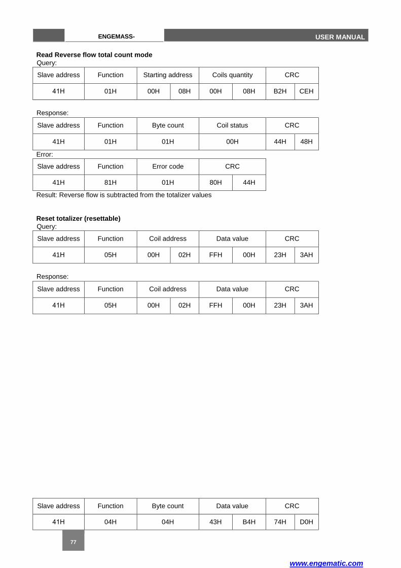
www.engematic.com
ENGEMASS-
CMF USER MANUAL
Read Reverse flow total count mode
Query:
Slave address Function Starting address Coils quantity CRC
41Н 01H 00H 08H 00H 08H B2H CEH
Response:
Slave address Function Byte count Coil status CRC
41H 01H 01H 00H 44H 48H
Error:
Slave address Function Error code CRC
41H 81H 01H 80H 44H
Result: Reverse flow is subtracted from the totalizer values
Reset totalizer (resettable)
Query:
Slave address Function Coil address Data value CRC
41Н 05H 00H 02H FFH 00H 23H 3AH
Response:
Slave address Function Coil address Data value CRC
41Н 05H 00H 02H FFH 00H 23H 3AH
Slave address Function Byte count Data value CRC
41Н 04H 04H 43H B4H 74H D0H
77

www.engematic.com
110 110
ENGEMASS-
CMF
USER MANUAL
Error:
Slave address Function Error code CRC
41H 85H 01H 82H 84H
Perform zero calibration
Query:
Slave address Function Coil address Data value CRC
41Н 05H 00H 04H FFH 00H C3H 3BH
Response:
Slave address Function Coil address Data value CRC
41Н 05H 00H 04H FFH 00H C3H 3BH
Error:
Slave address Function Error code CRC
41H 85H 01H 82H 84H
Read mass flow rate Query:
Slave address Function Starting address Registers quantity CRC
41Н 04H 00H A7H 00H 02H CEH E8H
Response:
Error:
Slave address Function Error code CRC
41H 84H 01H 83H 14H
Result: mass flow rate is 360.9126 kg/s
Write mass unit of kg Query:
Slave address Function Register address Data value CRC
41H 06H 00H 15H 00H 01H 57H 0EH
Response:
Slave address Function Register address Data value CRC
41H 06H 00H 15H 00H 01H 57H 0EH
Error:
Slave address Function Error code CRC
41H 86H 01H 82H 74H
Write calibration coefficient K = 1100 g/s/µs
Query:
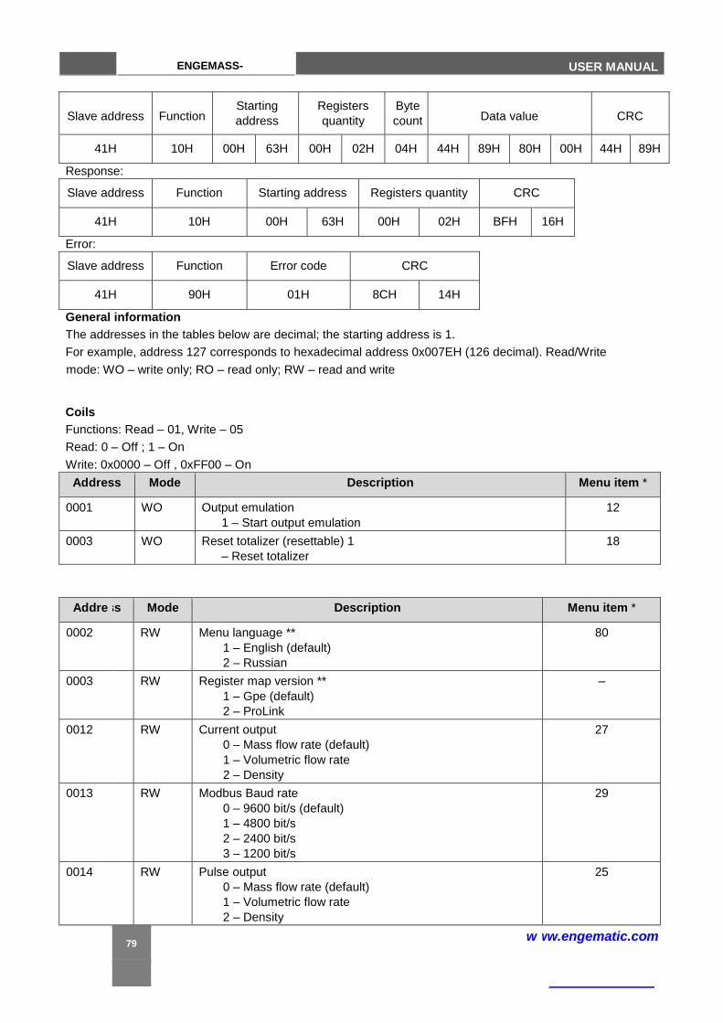
ENGEMASS-
CMF USER MANUAL
Slave address Function Starting
address
Registers
quantity
Byte
count
Data value
CRC
41H 10H 00H 63H 00H 02H 04H 44H 89H 80H 00H 44H 89H
Response:
Slave address Function Starting address Registers quantity CRC
41H 10H 00H 63H 00H 02H BFH 16H
Error:
Slave address Function Error code CRC
41H 90H 01H 8CH 14H
General information
The addresses in the tables below are decimal; the starting address is 1.
For example, address 127 corresponds to hexadecimal address 0x007EH (126 decimal). Read/Write
mode: WO – write only; RO – read only; RW – read and write
Coils
Functions: Read – 01, Write – 05
Read: 0 – Off ; 1 – On
Write: 0x0000 – Off , 0xFF00 – On
Address Mode Description Menu item *
0001 WO Output emulation
1 – Start output emulation
12
0003 WO Reset totalizer (resettable) 1
– Reset totalizer
18
Addre ss Mode Description Menu item *
0002 RW Menu language **
1 – English (default)
2 – Russian
80
0003 RW Register map version **
1 – Gpe (default)
2 – ProLink
–
0012 RW Current output
0 – Mass flow rate (default)
1 – Volumetric flow rate
2 – Density
27
0013 RW Modbus Baud rate
0 – 9600 bit/s (default)
1 – 4800 bit/s
2 – 2400 bit/s
3 – 1200 bit/s
29
0014 RW Pulse output
0 – Mass flow rate (default)
1 – Volumetric flow rate
2 – Density
25
79
w ww.engematic.com

www.engematic.com
112 112
ENGEMASS-
CMF
USER MANUAL
0004 WO Reset totalizer (inventory) ** 1
– Reset totalizer
–
0005 WO Zero calibration
1 – Start zero calibration
16
0009 RW Reverse flow total count mode
0 – Subtract from the totalizer (default)
1 – Add to the totalizer
20
0011 RW Oil-water analyze (pure oil counting)
0 – Off (default)
1 – On
52
0013 RW Multipoint correction
0 – Off
1 – On
81
0082 RW Pressure compensation
0 – Off (default)
1 – On
39
* For Menu items refer to display menu structure in Figure 2.14 and menu items description in Table 2.7.
** To write in registers the switches 2-4-6-8 must be in ON position.
16-bit registers – integer values
2 bytes, high byte first
Functions: Read – 04, Write – 06
Address Mode Description Menu item *
0015 RW Zero correction 67
0016 RW Reserved ***
0017 RW Flow direction
0 – Single direction (default)
1 – Bidirectional
19
0018 RW Mass flow rate unit
0 – g/s
1 – kg/s
2 – kg/min
3 – t/day
4 – kg/h (default)
5 – t/h
33
0019 RW Density unit 3 0 – g/cm (default) 1 – kg/L 3 2 – kg/m
36
0020 RW Temperature unit
0 – °С (default) 0 –
F
37
0021 RW Volumetric flow rate unit
0 – mL/s
1 – L/s
2 – L/min 3
3 – m /day
4 – L/h 3
5 – m /h (default)
35
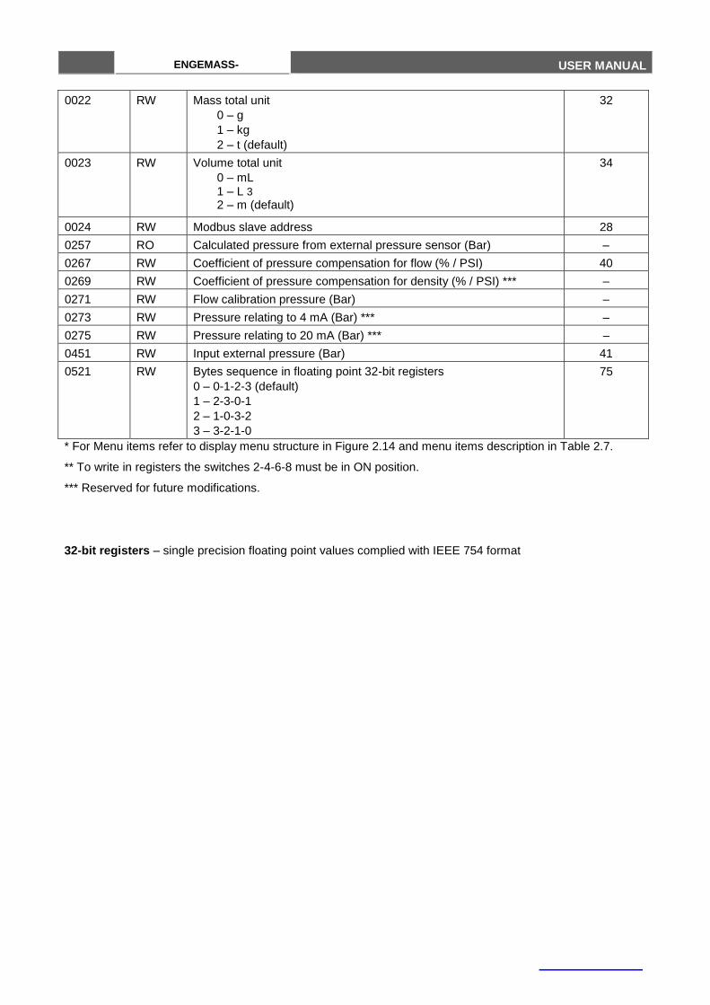
ENGEMASS-
CMF USER MANUAL
0022 RW Mass total unit
0 – g
1 – kg
2 – t (default)
32
0023 RW Volume total unit
0 – mL 1 – L 3 2 – m (default)
34
0024 RW Modbus slave address 28
0257 RO Calculated pressure from external pressure sensor (Bar) –
0267 RW Coefficient of pressure compensation for flow (% / PSI) 40
0269 RW Coefficient of pressure compensation for density (% / PSI) *** –
0271 RW Flow calibration pressure (Bar) –
0273 RW Pressure relating to 4 mA (Bar) *** –
0275 RW Pressure relating to 20 mA (Bar) *** –
0451 RW Input external pressure (Bar) 41
0521 RW Bytes sequence in floating point 32-bit registers
0 – 0-1-2-3 (default)
1 – 2-3-0-1
2 – 1-0-3-2
3 – 3-2-1-0
75
* For Menu items refer to display menu structure in Figure 2.14 and menu items description in Table 2.7.
** To write in registers the switches 2-4-6-8 must be in ON position.
*** Reserved for future modifications.
32-bit registers – single precision floating point values complied with IEEE 754 format
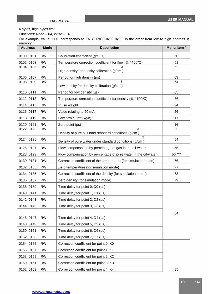
www.engematic.com
114 114
ENGEMASS-
CMF
USER MANUAL
4 bytes, high bytes first
Functions: Read – 04, Write – 16
For example, value “-1.5” corresponds to “0xBF 0xC0 0x00 0x00” in the order from low to high address in
memory.
Address Mode Description Menu item *
0100 0101 RW Calibration coefficient (g/s/µs) 60
0102 0103 RW Temperature correction coefficient for flow (% / 100ºС) 61
0104 0105 RW 3
High density for density calibration (g/cm ) 62
0106 0107 RW Period for high density (µs) 63
0108 0109 RW 3
Low density for density calibration (g/cm ) 64
0110 0111 RW Period for low density (µs) 65
0112 0113 RW Temperature correction coefficient for density (% / 100ºС) 66
0114 0115 RW Pulse weight 24
0116 0117 RW Value relating to 20 mA 26
0118 0119 RW Low flow cutoff (kg/h) 17
0120 0121 RW Zero point (µs) 16
0122 0123 RW 3
Density of pure oil under standard conditions (g/cm ) 53
0124 0125 RW 3
Density of pure water under standard conditions (g/cm ) 54
0126 0127 RW Flow compensation by percentage of gas in the oil-water 55
0128 0129 RW Flow compensation by percentage of pure water in the oil-water 56 ***
0130 0131 RW Correction coefficient of the temperature (for simulation mode) 76
0132 0133 RW Zero temperature (for simulation mode) 77
0134 0135 RW Correction coefficient of the density (for simulation mode) 78
0136 0137 RW Zero density (for simulation mode) 79
0138 0139 RW Time delay for point 0, D0 (µs)
84
0140 0141 RW Time delay for point 1, D1 (µs)
0142 0143 RW Time delay for point 2, D2 (µs)
0144 0145 RW Time delay for point 3, D3 (µs)
0146 0147 RW Time delay for point 4, D4 (µs)
0148 0149 RW Time delay for point 5, D5 (µs)
0150 0151 RW Time delay for point 6, D6 (µs)
0152 0153 RW Time delay for point 7, D7 (µs)
0154 0155 RW Correction coefficient for point 0, K0
85
0156 0157 RW Correction coefficient for point 1, K1
0158 0159 RW Correction coefficient for point 2, K2
0160 0161 RW Correction coefficient for point 3, K3
0162 0163 RW Correction coefficient for point 4, K4
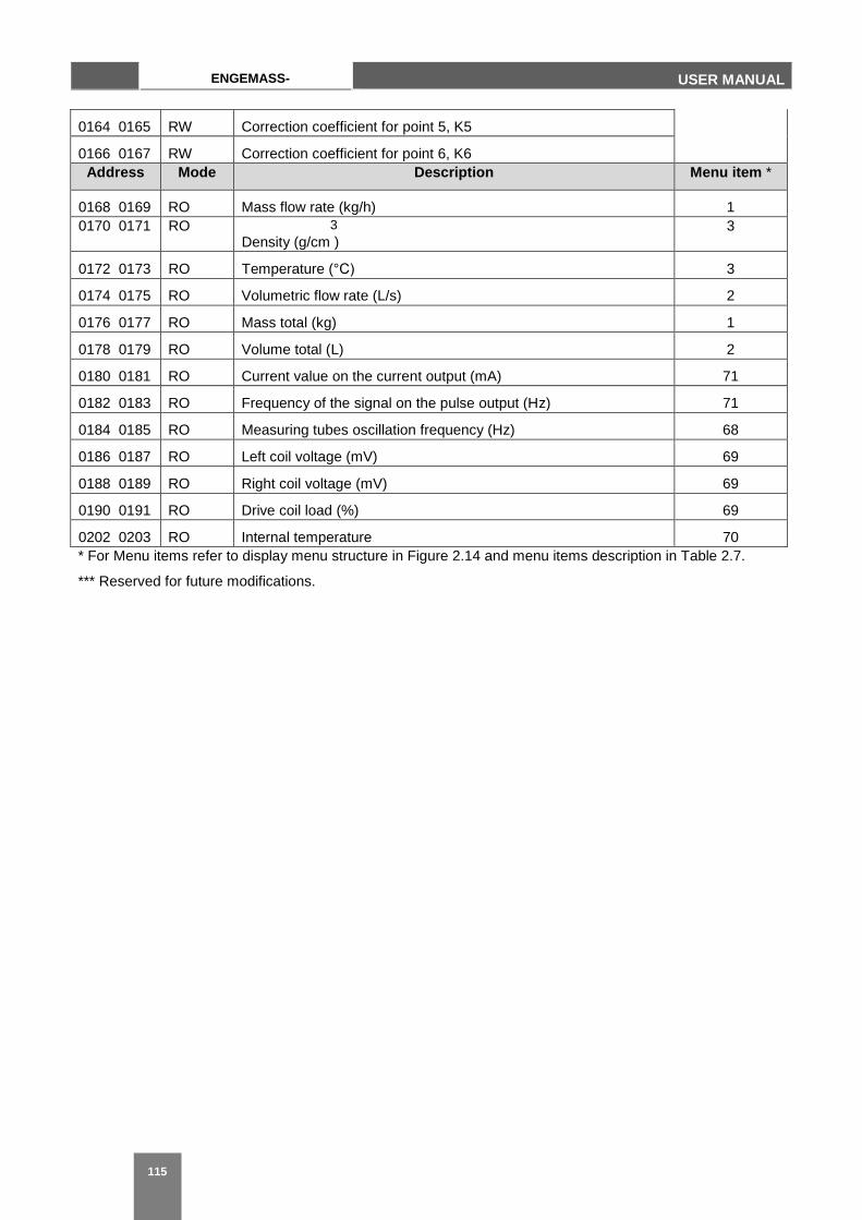
115
ENGEMASS-
CMF USER MANUAL
0164 0165 RW Correction coefficient for point 5, K5
0166 0167 RW Correction coefficient for point 6, K6
Address Mode Description Menu item *
0168 0169 RO Mass flow rate (kg/h) 1
0170 0171 RO 3
Density (g/cm ) 3
0172 0173 RO Temperature (°С) 3
0174 0175 RO Volumetric flow rate (L/s) 2
0176 0177 RO Mass total (kg) 1
0178 0179 RO Volume total (L) 2
0180 0181 RO Current value on the current output (mA) 71
0182 0183 RO Frequency of the signal on the pulse output (Hz) 71
0184 0185 RO Measuring tubes oscillation frequency (Hz) 68
0186 0187 RO Left coil voltage (mV) 69
0188 0189 RO Right coil voltage (mV) 69
0190 0191 RO Drive coil load (%) 69
0202 0203 RO Internal temperature 70
* For Menu items refer to display menu structure in Figure 2.14 and menu items description in Table 2.7.
*** Reserved for future modifications.
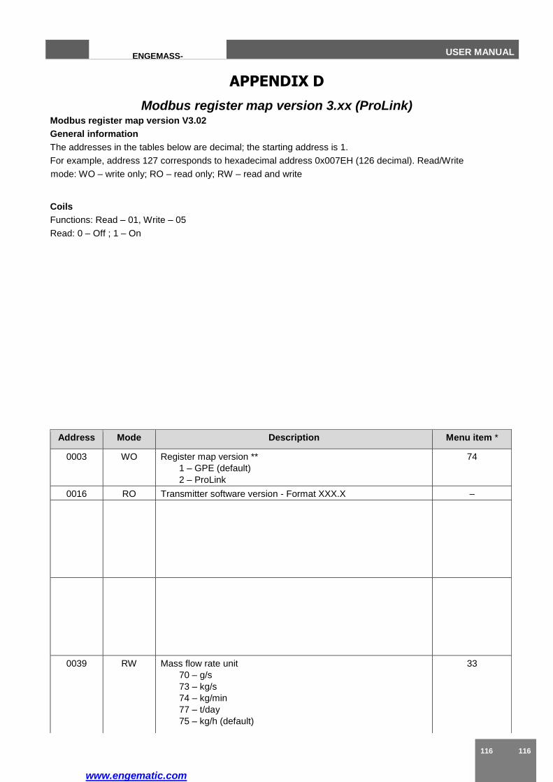
www.engematic.com
116 116
ENGEMASS-
CMF
USER MANUAL
APPENDIX D
Modbus register map version 3.xx (ProLink) Modbus register map version V3.02
General information
The addresses in the tables below are decimal; the starting address is 1.
For example, address 127 corresponds to hexadecimal address 0x007EH (126 decimal). Read/Write
mode: WO – write only; RO – read only; RW – read and write
Coils
Functions: Read – 01, Write – 05
Read: 0 – Off ; 1 – On
Address Mode Description Menu item *
0003 WO Register map version **
1 – GPE (default)
2 – ProLink
74
0016 RO Transmitter software version - Format XXX.X –
0039 RW Mass flow rate unit
70 – g/s
73 – kg/s
74 – kg/min
77 – t/day
75 – kg/h (default)
33
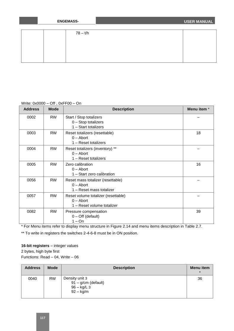
117
ENGEMASS-
CMF USER MANUAL
Write: 0x0000 – Off , 0xFF00 – On
Address Mode Description Menu item *
0002 RW Start / Stop totalizers
0 – Stop totalizers
1 – Start totalizers
–
0003 RW Reset totalizers (resettable)
0 – Abort
1 – Reset totalizers
18
0004 RW Reset totalizers (inventory) **
0 – Abort
1 – Reset totalizers
–
0005 RW Zero calibration
0 – Abort
1 – Start zero calibration
16
0056 RW Reset mass totalizer (resettable)
0 – Abort
1 – Reset mass totalizer
–
0057 RW Reset volume totalizer (resettable)
0 – Abort
1 – Reset volume totalizer
–
0082 RW Pressure compensation
0 – Off (default)
1 – On
39
* For Menu items refer to display menu structure in Figure 2.14 and menu items description in Table 2.7.
** To write in registers the switches 2-4-6-8 must be in ON position.
16-bit registers – integer values
2 bytes, high byte first
Functions: Read – 04, Write – 06
Address Mode Description Menu item
*
0040 RW Density unit 3 91 – g/cm (default) 96 – kg/L 3 92 – kg/m
36
78 – t/h
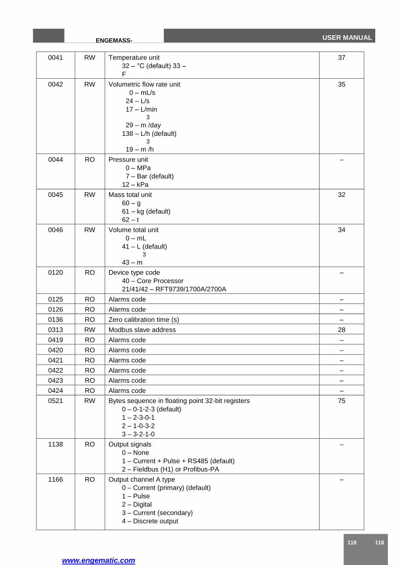
www.engematic.com
118 118
ENGEMASS-
CMF
USER MANUAL
0041 RW Temperature unit
32 – °С (default) 33 –
F
37
0042 RW Volumetric flow rate unit
0 – mL/s
24 – L/s
17 – L/min 3
29 – m /day
138 – L/h (default) 3
19 – m /h
35
0044 RO Pressure unit
0 – MPa
7 – Bar (default)
12 – kPa
–
0045 RW Mass total unit
60 – g
61 – kg (default)
62 – t
32
0046 RW Volume total unit
0 – mL
41 – L (default) 3
43 – m
34
0120 RO Device type code
40 – Core Processor
21/41/42 – RFT9739/1700A/2700A
–
0125 RO Alarms code –
0126 RO Alarms code –
0136 RO Zero calibration time (s) –
0313 RW Modbus slave address 28
0419 RO Alarms code –
0420 RO Alarms code –
0421 RO Alarms code –
0422 RO Alarms code –
0423 RO Alarms code –
0424 RO Alarms code –
0521 RW Bytes sequence in floating point 32-bit registers
0 – 0-1-2-3 (default)
1 – 2-3-0-1
2 – 1-0-3-2
3 – 3-2-1-0
75
1138 RO Output signals
0 – None
1 – Current + Pulse + RS485 (default)
2 – Fieldbus (H1) or Profibus-PA
–
1166 RO Output channel A type
0 – Current (primary) (default)
1 – Pulse
2 – Digital
3 – Current (secondary)
4 – Discrete output
–
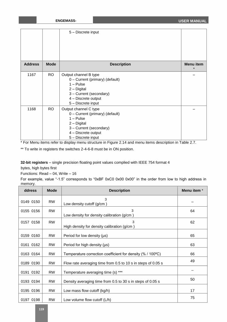
119
ENGEMASS-
CMF USER MANUAL
5 – Discrete input
Address Mode Description Menu item
*
1167 RO Output channel B type
0 – Current (primary) (default)
1 – Pulse
2 – Digital
3 – Current (secondary)
4 – Discrete output
5 – Discrete input
–
1168 RO Output channel C type
0 – Current (primary) (default)
1 – Pulse
2 – Digital
3 – Current (secondary)
4 – Discrete output
5 – Discrete input
–
* For Menu items refer to display menu structure in Figure 2.14 and menu items description in Table 2.7.
** To write in registers the switches 2-4-6-8 must be in ON position.
32-bit registers – single precision floating point values complied with IEEE 754 format 4
bytes, high bytes first
Functions: Read – 04, Write – 16
For example, value “-1.5” corresponds to “0xBF 0xC0 0x00 0x00” in the order from low to high address in
memory.
ddress Mode Description Menu item *
0149 0150 RW 3
Low density cutoff (g/cm ) –
0155 0156 RW 3
Low density for density calibration (g/cm ) 64
0157 0158 RW 3
High density for density calibration (g/cm ) 62
0159 0160 RW Period for low density (µs) 65
0161 0162 RW Period for high density (µs) 63
0163 0164 RW Temperature correction coefficient for density (% / 100ºС) 66
0189 0190 RW Flow rate averaging time from 0.5 to 10 s in steps of 0.05 s 49
0191 0192 RW Temperature averaging time (s) *** –
0193 0194 RW Density averaging time from 0.5 to 30 s in steps of 0.05 s 50
0195 0196 RW Low mass flow cutoff (kg/h) 17
0197 0198 RW Low volume flow cutoff (L/h) 75
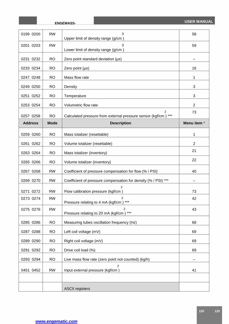
www.engematic.com
120 120
ENGEMASS-
CMF
USER MANUAL
0199 0200 RW 3
Upper limit of density range (g/cm ) 58
0201 0203 RW 3
Lower limit of density range (g/cm ) 59
0231 0232 RO Zero point standard deviation (µs) –
0233 0234 RO Zero point (µs) 16
0247 0248 RO Mass flow rate 1
0249 0250 RO Density 3
0251 0252 RO Temperature 3
0253 0254 RO Volumetric flow rate 2
0257 0258 RO 2
Calculated pressure from external pressure sensor (kgf/cm ) *** 73
Address Mode Description Menu item *
0259 0260 RO Mass totalizer (resettable) 1
0261 0262 RO Volume totalizer (resettable) 2
0263 0264 RO Mass totalizer (inventory) 21
0265 0266 RO Volume totalizer (inventory) 22
0267 0268 RW Coefficient of pressure compensation for flow (% / PSI) 40
0269 0270 RW Coefficient of pressure compensation for density (% / PSI) *** –
0271 0272 RW 2
Flow calibration pressure (kgf/cm ) 73
0273 0274 RW 2
Pressure relating to 4 mA (kgf/cm ) *** 42
0275 0276 RW 2
Pressure relating to 20 mA (kgf/cm ) *** 43
0285 0286 RO Measuring tubes oscillation frequency (Hz) 68
0287 0288 RO Left coil voltage (mV) 69
0289 0290 RO Right coil voltage (mV) 69
0291 0292 RO Drive coil load (%) 69
0293 0294 RO Live mass flow rate (zero point not counted) (kg/h) –
0451 0452 RW 2
Input external pressure (kgf/cm ) 41
ASCII registers

121
ENGEMASS-
CMF USER MANUAL
0072,
0073, 0074
RW Calibration coefficient (g/s/µs)
Format: XXXXXX Example: “23.350” , K=23.35 g/s/µs
40
0075, 0076 RW Temperature correction coefficient for flow Kt (%/100ºС)
Format: XXXX Example: “5.00” , Kt=5.0 %/100ºС
61
* For Menu items refer to display menu structure in Figure 2.14 and menu items description in Table 2.7.
*** Reserved for future modifications.
www.engematic.com