TÜV 13 ATEX 7399 X - ksr-kuebler.com · -ADF e AVK ADF Level ... aplicador deverá colocar uma...
28
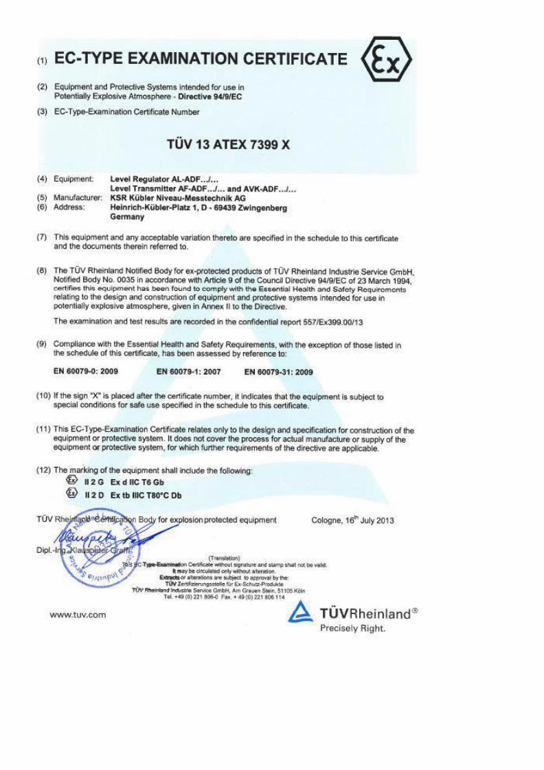
Manual de instruções e de operação Mounting and operating instruction TÜV 13 ATEX 7399 X Favor guardar para uso futuro Please retain for future usage Veuillez conserver pour un usage futur Sensor de nível AF-ADF e AVK-ADF Level Sensors AF-ADF and AVK-ADF Rev. 4 – 16.04.2015 Based on Rev. 3 – 02.04.2014
Transcript of TÜV 13 ATEX 7399 X - ksr-kuebler.com · -ADF e AVK ADF Level ... aplicador deverá colocar uma...
Manual de instruções e de operação
Mounting and operating instruction
TÜV 13 ATEX 7399 X
Favor guardar para uso futuro Please retain for future usage
Veuillez conserver pour un usage futur
Sensor de nível AF-ADF e AVK-ADF Level Sensors AF-ADF and AVK-ADF
Rev. 4 – 16.04.2015 Based on Rev. 3 – 02.04.2014
Índice
Português ......................................................................................................................................................... 1
Esclarecimento de símbolos .............................................................................................................................. 1 Referências de segurança ................................................................................................................................. 2
Perigo! ............................................................................................................................................................ 2 Utilização e âmbito de aplicação ........................................................................................................................ 3
Remoção da embalagem e de componentes de segurança no transporte ................................................... 3 Montagem e Instalação no recipiente ............................................................................................................. 4
Comprimentos máximos dos tubos deslizantes ......................................................................... 6 Conexão elétrica ............................................................................................................................................ 6
Serviços de ajustagem .............................................................................................................. 6 Seleção do cabo de ligação ...................................................................................................... 7 Capacidade de condução e de indutância ................................................................................. 7 Conexão do cabo ...................................................................................................................... 7 Compensação de potencial e conexão PE ................................................................................ 8
Manutenção .................................................................................................................................................... 8 Verificação de funcionalidade ........................................................................................................................ 8 Advertência ..................................................................................................................................................... 8 Busca de falhas .............................................................................................................................................. 9
Dados técnicos - sensor de nível AF - ADF ............................................................................... 10
Dados elétricos ....................................................................................................................... 10 Temperaturas ......................................................................................................................... 10 Pressão nominal ..................................................................................................................... 10
English ............................................................................................................................................................ 11
Symbol legend ................................................................................................................................................. 11 Safety information ............................................................................................................................................ 12
Danger! ......................................................................................................................................................... 12 Application and field of use .............................................................................................................................. 13
Removal of transport packaging and transport safety devices .................................................................... 13 Installation in the container ........................................................................................................................... 14
Maximum length of guide tubes .............................................................................................. 16 Electrical connection .................................................................................................................................... 16
Calibration .............................................................................................................................. 16 Selecting the connection cable ................................................................................................ 17 Conduction capacity and inductance ....................................................................................... 17 Cable Connection ................................................................................................................... 17 Equipotential bonding and PE connection ............................................................................... 18
Maintenance ................................................................................................................................................. 18 Functional test .............................................................................................................................................. 19 Note .............................................................................................................................................................. 19 Error search .................................................................................................................................................. 20
Technical data Level Sensors AF-ADF ...................................................................................... 20
electrical data ......................................................................................................................... 20 Temperatures ......................................................................................................................... 20 Nominal pressure .................................................................................................................... 20
KSR KUEBLER AG ....................................................................................................................... 21
Page 1 of 21
Mensagem de advertência
Português
Esclarecimento de
símbolos
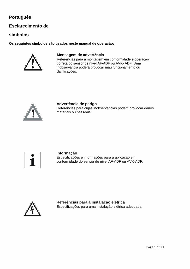
Os seguintes símbolos são usados neste manual de operação:
Advertência de perigo Referências para cujas inobservâncias podem provocar danos materiais ou pessoais.
Informação Especificações e informações para a aplicação em conformidade do sensor de nível AF-ADF ou AVK-ADF.
Referências para a instalação elétrica Especificações para uma instalação elétrica adequada.
Mensagem de advertência Referências para a montagem em conformidade e operação correta do sensor de nível AF-ADF ou AVK- ADF. Uma inobservância poderá provocar mau funcionamento ou danificações.
Page 2 of 21
Referências de segurança Leia este manual antes de instalar e operar o sensor de nível AF-ADF ou AVK-ADF.
Este manual é destinado a profissionais que executam o encaixe, a instalação e a configuração. Para a
instalação, devem ser observadas as normas relevantes de segurança.
Intervenção não autorizada e uso desautorizado provocam perda da garantia e de reivindicações de responsabilidade.
Devem ser tomadas providências para, em caso de defeito do sensor de nível AF - ADF
se evitem perigos para pessoas e materiais.
Não opere o sensor de nível AF-ADF ou AVK-ADF nas imediações de campos eletromagnéticos fortes. (Afastamento mínimo 1m)
Os sensores de nível AF-ADF ou AVK-ADF não podem ser submetidos a cargas mecânicas pesadas.
Os valores máximos de corrente e de tensão informados na montagem e no manual de operações devem ser obedecidos.
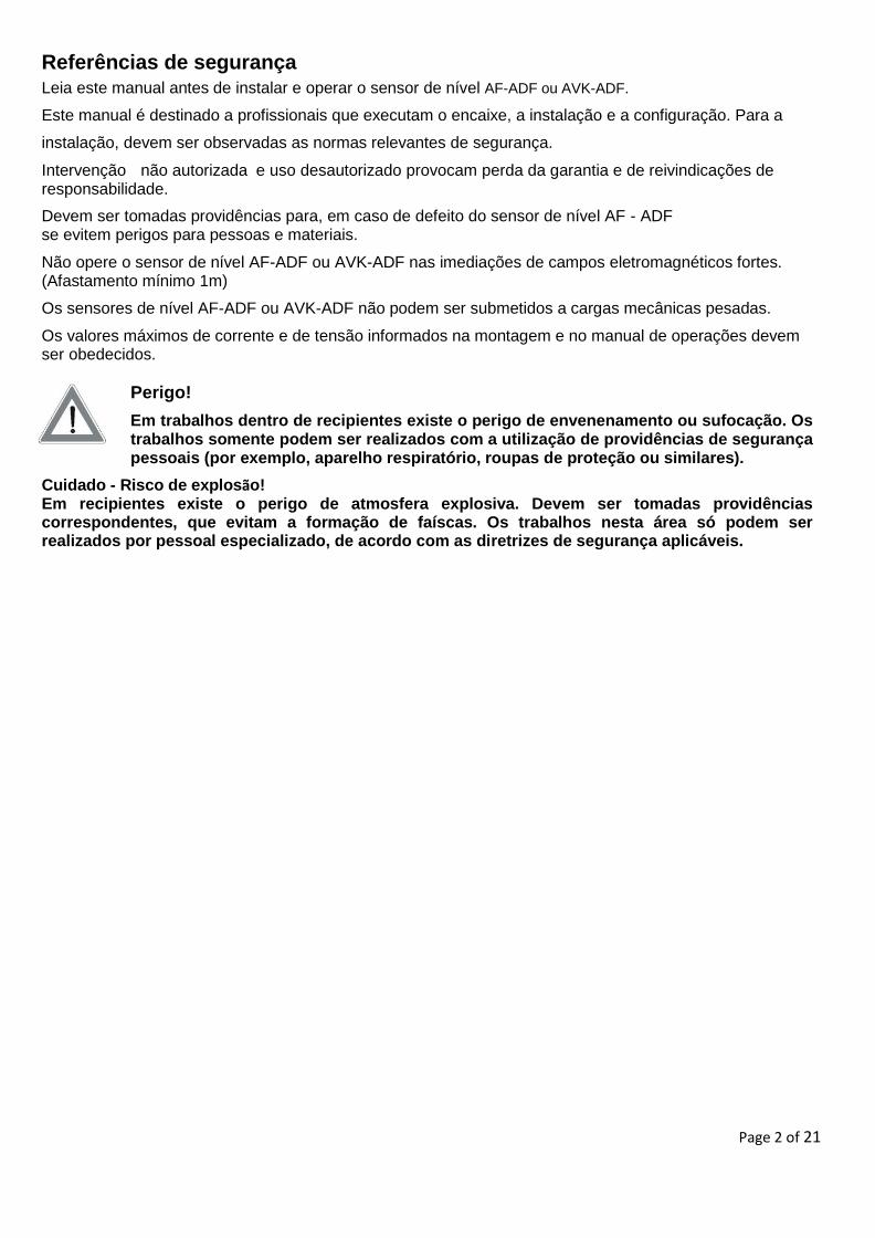
Perigo!
Em trabalhos dentro de recipientes existe o perigo de envenenamento ou sufocação. Os trabalhos somente podem ser realizados com a utilização de providências de segurança pessoais (por exemplo, aparelho respiratório, roupas de proteção ou similares).
Cuidado - Risco de explosão! Em recipientes existe o perigo de atmosfera explosiva. Devem ser tomadas providências correspondentes, que evitam a formação de faíscas. Os trabalhos nesta área só podem ser realizados por pessoal especializado, de acordo com as diretrizes de segurança aplicáveis.
Page 3 of 21
Utilização e âmbito de aplicação
Os sensores de nível AF-ADF ou AVK-ADF são aprovados para uso como equipamento à prova de explosão, no âmbito da diretriz CE 94/9 / CE em ambientes suscetíveis a explosões. Eles cumprem os requisitos de equipamentos elétricos para áreas suscetíveis a explosões. Os dados técnicos deste manual de operações devem ser observados.
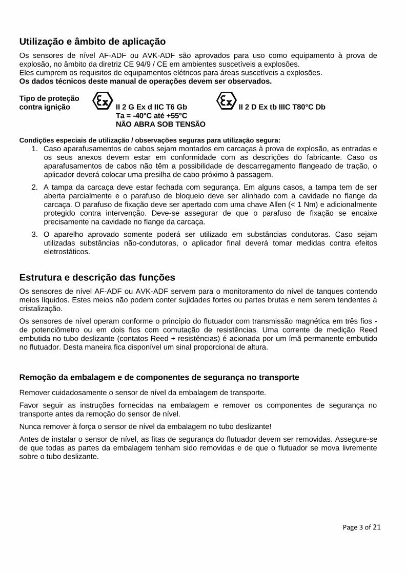
Tipo de proteção contra ignição II 2 G Ex d IIC T6 Gb II 2 D Ex tb IIIC T80°C Db
Ta = -40°C até +55°C NÃO ABRA SOB TENSÃO
Condições especiais de utilização / observações seguras para utilização segura:
1. Caso aparafusamentos de cabos sejam montados em carcaças à prova de explosão, as entradas e os seus anexos devem estar em conformidade com as descrições do fabricante. Caso os aparafusamentos de cabos não têm a possibilidade de descarregamento flangeado de tração, o aplicador deverá colocar uma presilha de cabo próximo à passagem.
2. A tampa da carcaça deve estar fechada com segurança. Em alguns casos, a tampa tem de ser aberta parcialmente e o parafuso de bloqueio deve ser alinhado com a cavidade no flange da carcaça. O parafuso de fixação deve ser apertado com uma chave Allen (< 1 Nm) e adicionalmente protegido contra intervenção. Deve-se assegurar de que o parafuso de fixação se encaixe precisamente na cavidade no flange da carcaça.
3. O aparelho aprovado somente poderá ser utilizado em substâncias condutoras. Caso sejam utilizadas substâncias não-condutoras, o aplicador final deverá tomar medidas contra efeitos eletrostáticos.
Estrutura e descrição das funções
Os sensores de nível AF-ADF ou AVK-ADF servem para o monitoramento do nível de tanques contendo meios líquidos. Estes meios não podem conter sujidades fortes ou partes brutas e nem serem tendentes à cristalização.
Os sensores de nível operam conforme o princípio do flutuador com transmissão magnética em três fios - de potenciômetro ou em dois fios com comutação de resistências. Uma corrente de medição Reed embutida no tubo deslizante (contatos Reed + resistências) é acionada por um ímã permanente embutido no flutuador. Desta maneira fica disponível um sinal proporcional de altura.
Remoção da embalagem e de componentes de segurança no transporte
Remover cuidadosamente o sensor de nível da embalagem de transporte.
Favor seguir as instruções fornecidas na embalagem e remover os componentes de segurança no transporte antes da remoção do sensor de nível.
Nunca remover à força o sensor de nível da embalagem no tubo deslizante!
Antes de instalar o sensor de nível, as fitas de segurança do flutuador devem ser removidas. Assegure-se de que todas as partes da embalagem tenham sido removidas e de que o flutuador se mova livremente sobre o tubo deslizante.
Page 4 of 21
Montagem e Instalação no recipiente
Os sensores de nível são instalados no recipiente por meio de flange ou rosca de aparafusamento, dependendo do modelo. (Por favor, a variante da montagem do seu sensor de nível você infere na designação de tipo existente no produto)
Antes da instalação, verifique se o recipiente adequado no orifício de montagem e o dispositivo de fixação do sensor de nível coincidam em tamanho e no dimensionamento.
A instalação é realizada, dependendo da versão do sensor de nível AF-ADF ou AVK-ADF pelo lado de fora no recipiente. Eles devem ser instalados em uma posição vertical. Para garantir uma operação segura, o ângulo de instalação permitido pode variar no máximo 30° a partir da vertical.
O tubo deslizante do sensor de nível AF-ADF ou AVK-ADF deve ser inserido através do orifício de montagem do recipiente. A fixação ocorrerá através de aperto da rosca de aparafusamento ou dos parafusos nas versões flangeadas.
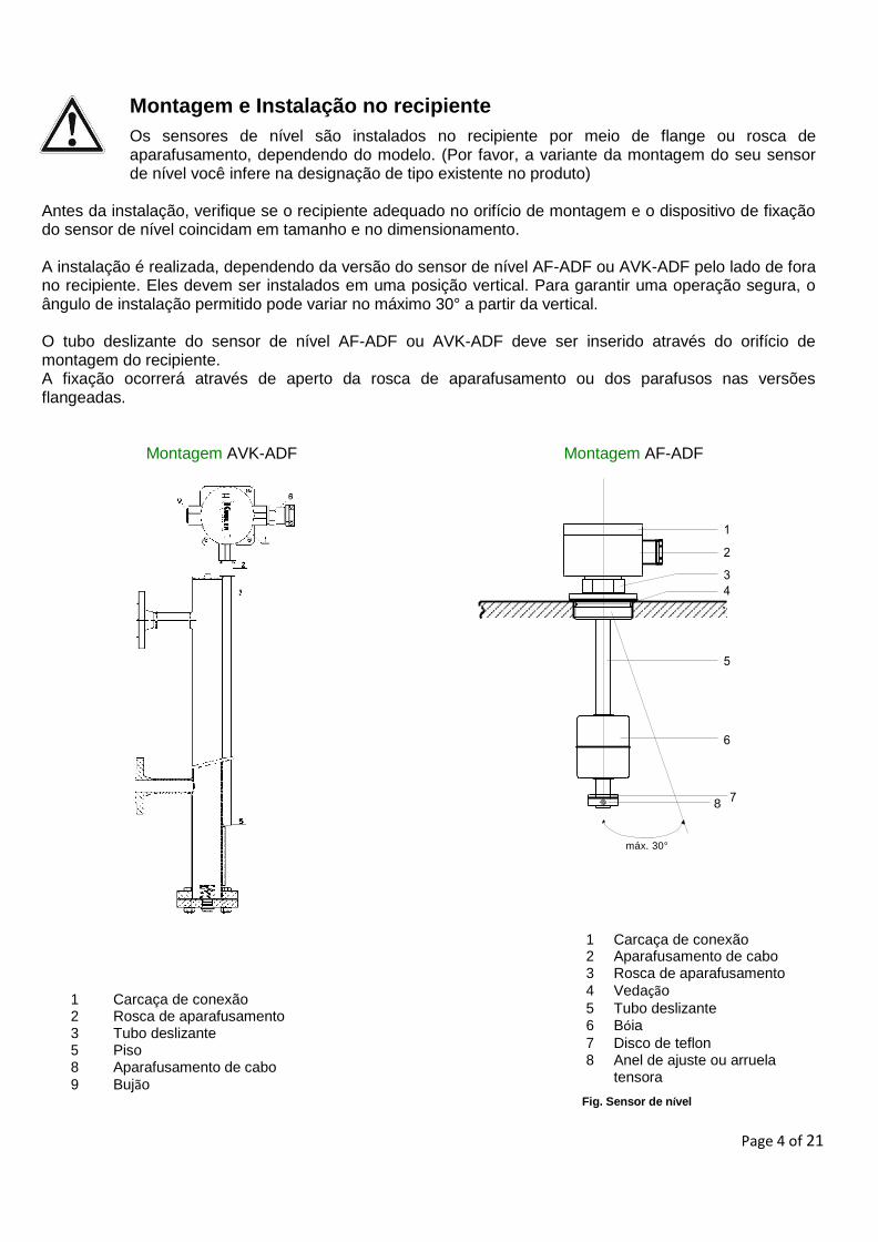
Montagem AVK-ADF Montagem AF-ADF
máx. 30°
1 Carcaça de conexão 2 Rosca de aparafusamento 3 Tubo deslizante 5 Piso 8 Aparafusamento de cabo
9 Bujão
1 Carcaça de conexão 2 Aparafusamento de cabo 3 Rosca de aparafusamento
4 Vedação
5 Tubo deslizante 6 Bóia
7 Disco de teflon 8 Anel de ajuste ou arruela
tensora
Fig. Sensor de nível
8
Page 5 of 21
Os sensores de nível com rosca de aparafusamento são aparafusados no comprimento total da rosca. Os sensores de nível com versão flangeada devem ser fixados com parafusos, arruelas e porcas apropriados. Por favor, observe os valores de torque dos parafusos dos parafusos.
Deve-se utilizar vedações adequadas. Deve-se assegurar de que o material de vedação seja resistente ao meio e seus vapores, bem como às cargas de temperatura e de pressão esperadas.
Em variantes com flutuadores sobrepostos, cujo diâmetro seja maior do que o diâmetro do núcleo do orifício de montagem, os flutuadores devem ser destacados do tubo deslizante antes da instalação.
Modo de atuação:
1. Marcar a parte superior da bóia (por exemplo, com "topo") 2. Marcar a posição dos anéis de ajuste a remover 3. Remover os anéis de ajuste e de proteção anti-quedas 4. Remover bóia 5. Montar sensor de nível AF-ADF 6. Posicionar flutuadores, anéis de ajuste e de proteção anti-quedas a partir do interior do recipiente.
Observar marcações!
Os anéis de proteção anti-quedas servem para evitar faíscas em caso de colisão do flutuador no anel de ajuste. Não é permitida uma operação sem anéis de proteção anti-quedas.
Page 6 of 21
Comprimentos máximos dos tubos deslizantes
Em recipientes onde se preveem turbulências, os sensores de nível devem ser fixados em um mangote de recebimento no fundo deste recipiente, em função do comprimento.
Conexão elétrica
Trabalhos de conexão na caixa de bornes só podem ser executados com a energia desligada.
O tipo de proteção da ignição depende da adequada seleção e instalação de cabos e guias correspondentes de inserção, bem como dos tampões de vedação. Somente podem ser utilizados cabos e guias certificados de acordo com as normas EN 60079-0 e EN 60079-1 com um certificado destacado de exame CE para obras. Estes devem ser certificados, ao menos para a mesma faixa de temperaturas do medidor de nível completo. Além disto, deve-se observar que o tamanho da rosca e o seu acabamento devem corresponder ao da versão do dispositivo correspondente. Não é permitida a utilização de tranças individuais! Em caso de inobservância, a autorização do modo construtivo expira.
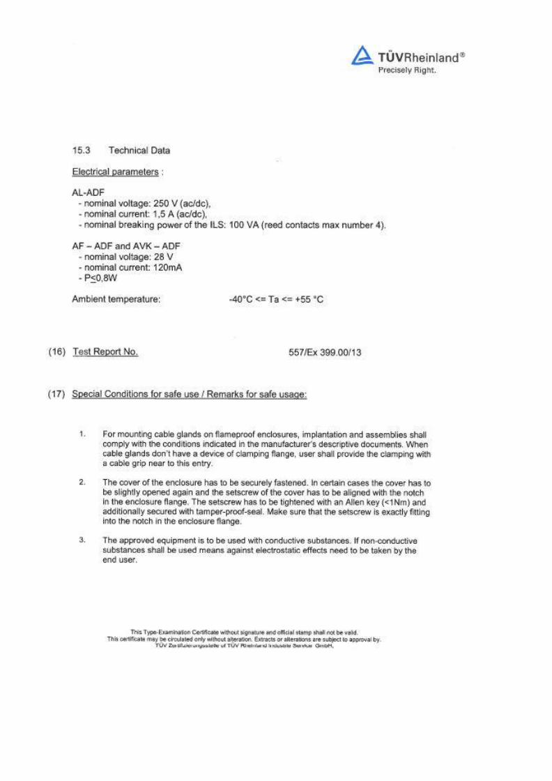
Os sensores de nível AF-ADF ou AVK-ADF só podem ser operados em circuitos de comando com os seguintes valores máximos:
Sem transdutor medidor U ≤ 28 V, I ≤ 120mA Com transdutor medidor U ≤ 28 V, l ≤ 120 mA- P ≤ 0,8 W
Sensor de nível AF-ADF ou AVK-ADF II 2 G Ex d IIC T6 Gb II 2 D Ex tb IIIC T80°C Db
Devem ser observados os dados elétricos na placa de identificação e os regulamentos adicionais para a instalação de circuitos elétricos. Estes trabalhos somente devem ser realizados por pessoal especializado e treinado.
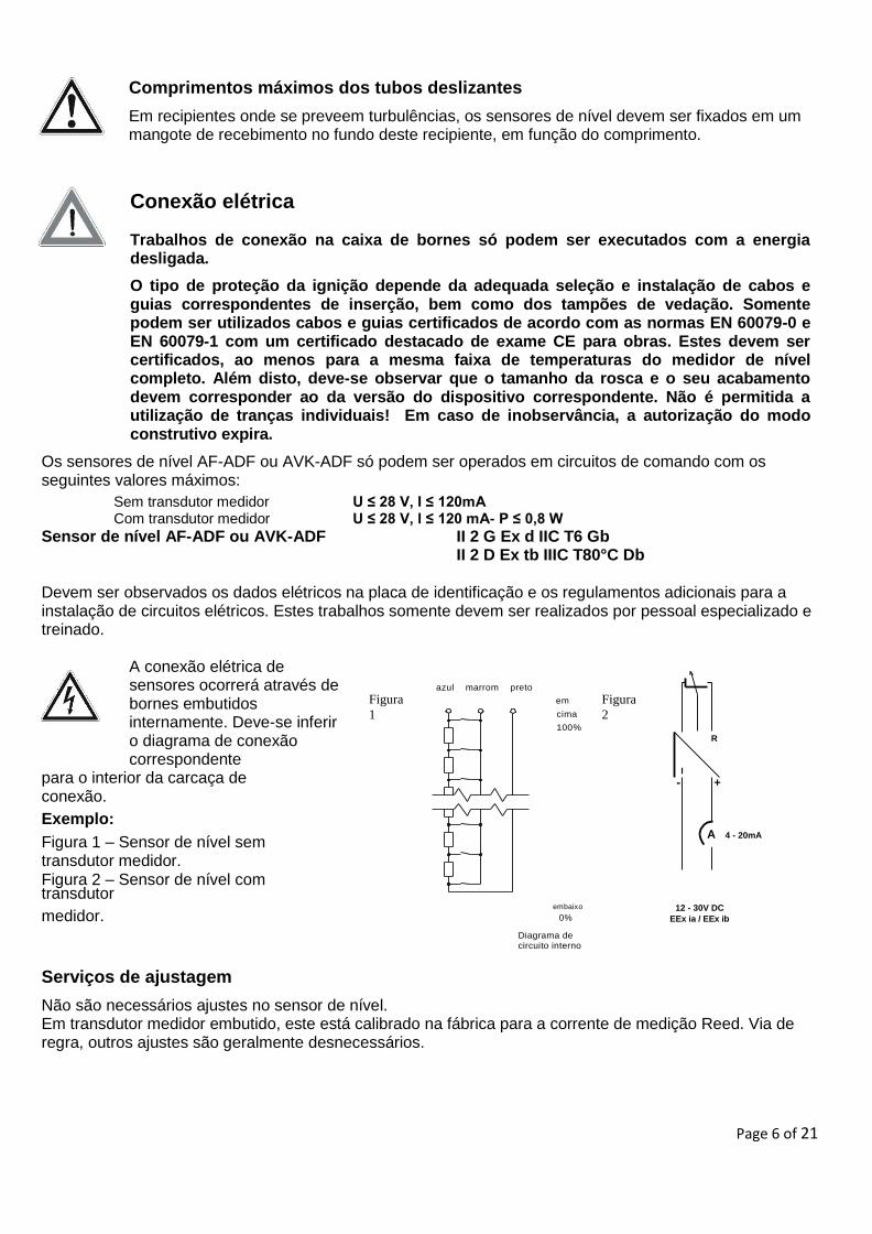
A conexão elétrica de sensores ocorrerá através de bornes embutidos internamente. Deve-se inferir o diagrama de conexão correspondente
para o interior da carcaça de conexão.
Exemplo:
Figura 1 – Sensor de nível sem transdutor medidor. Figura 2 – Sensor de nível com transdutor
Figura
1
azul marrom preto
em
cima
100%
Figura
2
R
I
- +
A 4 - 20mA
medidor. embaixo
0%
Diagrama de circuito interno
12 - 30V DC
EEx ia / EEx ib
Serviços de ajustagem
Não são necessários ajustes no sensor de nível. Em transdutor medidor embutido, este está calibrado na fábrica para a corrente de medição Reed. Via de regra, outros ajustes são geralmente desnecessários.
Page 7 of 21
Seleção do cabo de ligação
O cabo de conexão deve ser selecionado de modo que seja adequado para as condições ambientais esperadas (temperaturas, atmosfera agressiva, influências climáticas, etc.)
. Dependendo do versão do sensor de nível são necessários 3 - 5 nervuras.
Deve-se observar o diagrama de conexão correspondente.
O cabo de conexão deve atender as especificações do fabricante de aparafusamento de cabo utilizado. Não é permitida a utilização de tranças individuais! Em caso de inobservância, a autorização do modo construtivo expira.
Capacidade de condução e de indutância
Na determinação do comprimento requerido de cabo devem ser observadas as indutâncias e as capacitâncias máximas admissíveis do dispositivo avaliador conectado. Estes valores não devem ser excedidos
pelo cabo de conexão.
Conexão do cabo
Trabalhos de conexão na caixa de bornes só podem ser executados com a energia desligada.
O cabo de conexão deve ser instalado de acordo com as prescrições vigentespara o estabelecimento de circuitos de corrente
1. Desligar a corrente do sensor de nível AF-ADF ou AVK-ADF
2. Remover a tampa da carcaça de bornes
3. Inserir o cabo na carcaça de bornes através do aparafusamento de cabo
4. Isolar as tranças e a camisa
5. Prover as tranças com buchas aderentes
6. Inserir e fixar as nervuras de acordo com as prescrições correspondentes nos bornes
seriais
7. Apor a tampa da carcaça e fixá-la A tampa da carcaça deve ser aparafusada até ao batente. Se necessário, a tampa deve ser reaberta um pouco para posicionar o pino roscado na tampa em alinhamento com o recesso no flange da carcaça. Além disso, o parafuso de ajuste deve ser apertado utilizando-se uma chave de fenda hexagonal com torque <1Nm e fixada com tinta adesiva bloqueadora.
8. Favor observar que o pino roscado deve se engastar no recesso
previsto no flange !
Deve-se observar o diagrama de conexão correspondente
Page 8 of 21
Compensação de potencial e conexão PE
Na carcaça de conexão do sensor de nível AF-ADF ou AVK-ADF está disponível pelo menos uma conexão PE para conexão de um condutor PE. Em sensores de nível sem terminal de aterramento externo deve-se implantar durante a instalação uma conexão elétrica para o recipiente.Em caso de terminal de aterramento presente, a compensação de potencial ou a conexão PE pode ser realizada através do mesmo.
Manutenção
Os sensores de nível AF-ADF ou AVK-ADF trabalham sem manutenção em caso de utilização em conformidade. Entretanto, como parte da revisão regular eles devem ser submetidos a uma inspeção visual e incluídas no teste de pressão do recipiente.
Teste funcional
O teste funcional somente pode ser executado com sensor desmontado. Durante o teste funcional podem ser disparadas operações de processo não intencionais para comandos posteriores. Perigo de danos pessoais ou materiais.
1. Desligar a corrente do sensor de nível AF-ADF ou AVK-ADF 2. Retirar o cabo de conexão. 3. Conectar o ohmímetro em duas nervuras. 4. Mover manualmente o flutuador da posição Min. para a posição Máx. 5. O valor indicado de resistência se altera em função das cores das nervuras conectadas ( Tab. 1).
Nota
Durante o teste funcional podem ser disparadas operações de processo não intencionais para comandos posteriores. O teste funcional somente pode ser executado por pessoal treinado, observando-se as prescrições vigentes relativas à proteção contra explosões. Os meios e os equipamentos de teste e as ferramentas devem ser adequados para uso em
ambiente com risco de explosão. Ao usar o sensor de nível em uma atmosfera explosiva, o fornecimento de corrente deve ser desligado antes de se abrir a carcaça.
Perigo de danos pessoais ou materiais.
Somente em sensores com
comutação de potenciômetro
para três fios Preto - Marrom (R1) Azul - Marrom (R2) Preto - Azul (Ri) O valor da resistência aumenta proporcionalmente à altura do sistema magnético ascendente (bóia).
Sistema magnético (bóia) em cima -
indicação da resistência geral (Ri)
O valor da resistência diminui proporcionalmente à altura do sistema magnético ascendente (bóia). Sistema magnético (bóia) embaixo - indicação da resistência geral (Ri)
Indicação da
resistência geral (Ri)
Page 9 of 21
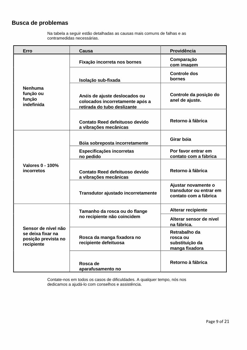
Busca de problemas
Na tabela a seguir estão detalhadas as causas mais comuns de falhas e as contramedidas necessárias.
Erro Causa Providência
Nenhuma função ou
função
indefinida
Fixação incorreta nos bornes Comparação
com imagem
de conexões
Isolação sub-fixada
Controle dos bornes
Anéis de ajuste deslocados ou
colocados incorretamente após a
retirada do tubo deslizante
Controle da posição do
anel de ajuste.
Contato Reed defeituoso devido a vibrações mecânicas
Retorno à fábrica
Valores 0 - 100% incorretos
Bóia sobreposta incorretamente
Girar bóia
Especificações incorretas
no pedido
Por favor entrar em
contato com a fábrica
Contato Reed defeituoso devido a vibrações mecânicas
Retorno à fábrica
Transdutor ajustado incorretamente
Ajustar novamente o transdutor ou entrar em contato com a fábrica
Sensor de nível não se deixa fixar na posição prevista no recipiente
Tamanho da rosca ou do flange no recipiente não coincidem
Alterar recipiente
Alterar sensor de nível
na fábrica.
Rosca da manga fixadora no recipiente defeituosa
Retrabalho da rosca ou substituição da
manga fixadora
Rosca de aparafusamento no sensor defeituosa
Retorno à fábrica
Contate-nos em todos os casos de dificuldades. A qualquer tempo, nós nos dedicamos a ajudá-lo com conselhos e assistência.
Page 10 of 21
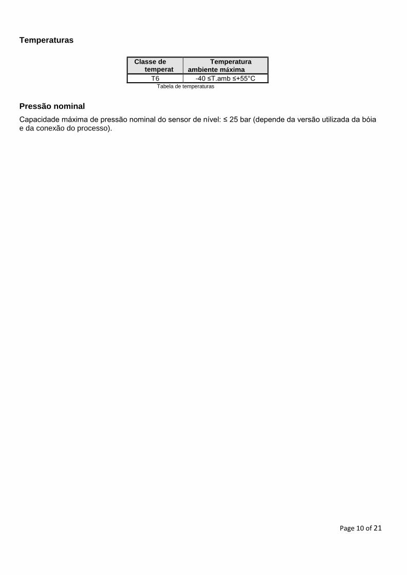
Temperaturas
Classe de temperatura
Temperatura ambiente máxima
T6 -40 ≤T.amb ≤+55°C Tabela de temperaturas
Pressão nominal
Capacidade máxima de pressão nominal do sensor de nível: ≤ 25 bar (depende da versão utilizada da bóia e da conexão do processo).
Page 11 of 21
English
Symbol legend
The following symbols are used in these operating instructions:
Warning Instructions on correct installation and proper operation of the Level Sensors AF-ADF or AVK-ADF. Failing to comply with these instructions can lead to malfunction of or damage to the switch.
Precaution Instructions which must be complied with to avoid injury or property damage or loss of the type permit.
Information Facts and information concerning proper operation of the Level Sensors AF-ADF or AVK-ADF.
Instructions for electrical installation Information on proper electrical installation.
Page 12 of 21
Safety information Read these instructions before installing the Level Sensors AF-ADF or AVK-ADF and putting then into operation.
These instructions are intended for the specialists in charge of mounting, installation and setup.
Comply with the relevant safety regulations when using the equipment.
Unauthorized access and impermissible use of the equipment will result in the loss of guarantee and liability protection.
Measures must be taken to prevent risks to persons and property in the event of a defect in the Level Sensors AF-ADF or AVK-ADF.
Do not operate Level Sensors AF-ADF or AVK-ADF in the immediate vicinity of strong electromagnetic fields (minimum distance: 1 m).
Level Sensors AF-ADF or AVK-ADF must not be exposed to heavy mechanical loads.
Comply with the maximum current and voltage values as specified in the installation and operating instructions.
Danger!
There is a risk of poisoning or suffocation when working in containers. Relevant personal protection measures (e.g. respiratory devices, protective clothing, etc.) must be taken before work is carried out.
Danger, risk of explosion! An explosive atmosphere may develop in a container. Measures must be taken to prevent sparking. Work in such areas must be done by qualified personnel in accordance with the relevant safety regulations and guidelines.
Page 13 of 21
Application and field of use
An approval has been issued for the Level Sensors AF-ADF or AVK-ADF for use as explosion-protected equipment within the scope of application defined by EC Guideline 94/9/EC in hazardous areas. They comply with the specifications regulating use of electrical equipment in explosion risk areas. The technical data in these operating instructions must be complied with.
Main protection type II 2 G Ex d IIC T6 Gb II 2 D Ex tb IIIC T80°C Db
Ta = -40°C zu +55°C DO NOT OPEN WHILE ENERGIZED
Special conditions for a safe use / Remarks for safe usage:
1. For mounting cable glands on flameproof enclosures, implantation and assemblies shall comply with the conditions indicated in the manufacturer’s descriptive documents. When cable glands don’t have a device of clamping flange, user shall provide the clamping with a cable grip near to this entry.
2. The cover of the enclosure has to be securely fastened. In certain cases the cover has to be slightly opened again the setscrew of the cover has to be aligned with the notch in the enclosure flange. The setscrew of the cover has to be tightened with an Allan key (<1 Nm) and additionally secured with tamper-proof-seal. Make sure that the setscrew is exactly fitting into the notch in the enclosure flange.
3. The approved equipment is to be used with conductive substances. If non-conductive substances shall be used means against electrostatic effects need to be taken by the end user.
Structure and functional description
AF-ADF or AVK-ADF Level Sensors are used to monitor the filling levels in containers with liquid mediums. These mediums must not contain any pronounced soiling or coarse particles and they must not tend to crystallize out.
The Sensors function according to the float principle with magnetic transmission in three-conductor potentiometer circuitry or two-conductor resistor circuitry. A reed measuring chain (reed contacts + resistors) installed in the sliding tube is actuated by a permanent magnet installed in the float. This provides a height-proportional resistance signal.
Removal of transport packaging and transport safety devices
Remove the Level Sensors carefully from the transport packaging.
See the instructions on the shipping packaging; remove all transport safety devices before removing the Level Sensors.
Never forcibly remove the Level Sensors from the packaging by taking hold of the guide tube!
Before installing the Level Sensors, the float safety bands must be removed. Make sure all packaging components have been removed and that the float moves freely on the guide tube.
Page 14 of 21
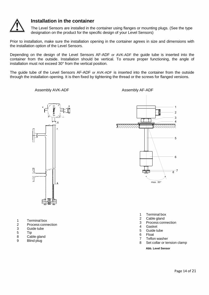
Installation in the container
The Level Sensors are installed in the container using flanges or mounting plugs. (See the type designation on the product for the specific design of your Level Sensors)
Prior to installation, make sure the installation opening in the container agrees in size and dimensions with the installation option of the Level Sensors.
Depending on the design of the Level Sensors AF-ADF or AVK-ADF the guide tube is inserted into the container from the outside. Installation should be vertical. To ensure proper functioning, the angle of installation must not exceed 30° from the vertical position.
The guide tube of the Level Sensors AF-ADF or AVK-ADF is inserted into the container from the outside through the installation opening. It is then fixed by tightening the thread or the screws for flanged versions.
Assembly AVK-ADF Assembly AF-ADF
1 Terminal box 2 Process connection 3 Guide tube 5 Tip 8 Cable gland 9 Blind plug
max. 30°
1 Terminal box 2 Cable gland 3 Process connection 4 Gasket 5 Guide tube 6 Float 7 Teflon washer 8 Set collar or tension clamp
Abb. Level Sensor
8
Page 15 of 21
In Level Sensors featuring a mounting plug, the thread must be screwed in for the entire length of the thread. Level Sensors featuring flanges must be installed using suitable bolts, washers and nuts. Please comply with the maximum torque ratings of the bolts / screws used when tightening them down.
Use suitable gaskets. Make sure the gasket material is resistant to the medium and its vapours as well as to the expected temperature and pressure loads.
Designs, where the float’s diameter is larger then the core opening must be installed with the float removed form the guide tube.
Procedure:
1. Mark the upper side of the float (e.g. with "top") 2. Mark position of the set collar to be removed 3. Remove set collars and teflon washer 4. Remove floats 5. Install Level Sensors AF-ADF or AVK-ADF
6. Position the floats, set collars and teflon washer from inside the container. Mind the marked positions!
The purpose of the teflon washer is to avoid potential ignition sparking if the float should fall against the set collar. Operating the equipment without teflon washer is not permitted.
Page 16 of 21
Maximum length of guide tubes
According to the length and the execution of the guide, transmitters ADF must possibly fixed with bottom of the tank.
Electrical connection
The voltage must be disconnected when electrical connections are being carried out in the terminal connection box. The type of protection depends on appropriate choose and installation of cable glands and blanking elements. Only cable glands with existing, separate EC-type examination certificates corresponding to EN 60079-0 and EN 60079-1 are applicable. These certified components have to at least fulfil minimal requirements of temperature range as the temperature range of the level transmitter gauge. It has to be considered to use appropriate type and size of threads as the type of apparatus' threads. Use of individual conductor strands is not permissible!
AF-ADF and AVK-ADF Level transmitters must only be operated on electrical power circuits with maximum levels as follows: Without signal converter U ≤ 28 V, I ≤ 120mA With signal converter U ≤ 28 V-I <120 mA- P ≤ 0,8 W
* When using a head-mounted transmitter, please note the following: If the electrical data of the head- mounted transmitter are lower than those listed above, the electrical data of the head-mounted transmitter shall be binding.
Level Sensor AF-ADF and AVK-ADF II 2 G Ex d IIC T6 Gb
II 2 D Ex tb IIIC T80°C Db
The electrical data on the type plate and the additional regulations governing electrical circuits must be complied with. This work must be done by trained specialist personnel.
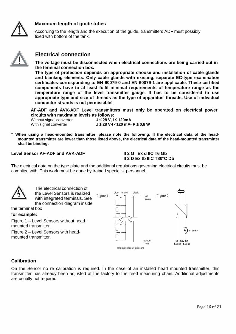
The electrical connection of the Level Sensors is realized with integrated terminals. See the connection diagram inside
the terminal box
for example:
Figure 1 – Level Sensors without head- mounted transmitter.
Figure 2 – Level Sensors with head- mounted transmitter.
Figure 1
blue brown black
top
100%
Figure 2
R
I
- +
A 4 - 20mA
botton
0% 12 - 30V DC
EEx ia / EEx ib
Internal circuuit diagram
Calibration
On the Sensor no re calibration is required. In the case of an installed head mounted transmitter, this transmitter has already been adjusted at the factory to the reed measuring chain. Additional adjustments are usually not required.
Page 17 of 21
Selecting the connection cable
The connection cable must be selected as suitable for the expected ambient conditions (temperature, aggressive atmosphere, weathering, etc.). According design there are 3 – 5 wires necessary
See the connection diagram in each case.
The connecting lead must meet the specifications of the manufacturer of the cable gland used. Use of individual conductor strands is not permissible! The corresponding Type Permit is no longer valid if this specification is not complied with.
Conduction capacity and inductance
When determining the required cable length, the maximum permissible inductances and capacities of the connected control device must be taken into account. These values should not be exceeded by the connection cable.
Cable Connection
The voltage must be disconnected when electrical connections are being carried out in the terminal connection box.
The connecting lead must be installed in accordance with the applicable regulations governing the installation of electrical circuits
1. Switch off circuit voltage for the Level Sensors AF-ADF or AVK-ADF
2. Remove the lid of the terminal box
3. Insert the cable through the cable gland collet into the terminal box
4. Remove jacketing and expose strands
5. Attach terminal lugs to the strands
6. Insert the wires into the row terminals as per diagram and fasten them down
7. The cover of the enclosure has to be security fastered.In cartain cases the cover
has to be aligned with the notch in the encolsure flange. The setsrew has to be
tightened with an allenkey (≤ 1Nm) and additionally secured with tamper proof
seal (loctite). Make sure the setsrew is exactly fitting into the notch in the
enclosure flange.
8. It is also recommended to affix a drop of loctite on the thumb screw.
Use the appropriate connection scheme
Page 18 of 21
Equipotential bonding and PE connection
There is at least one PE connection terminal for connection of a PE conductor in the terminal box of the Level Sensors AF-ADF or AVK-ADF. In the case of Level Sensors without external ground terminals, an electrical connection must be established between the mounting plug and
the container during installation. If there is a ground terminal, the equipotential bonding or PE connection can be realized by this means.
Maintenance
Level Sensors AF-ADF or AVK-ADF function free of maintenance if used properly. However, they must be subjected to a visual check within the framework of regular inspection, including a container pressure test.
Page 19 of 21
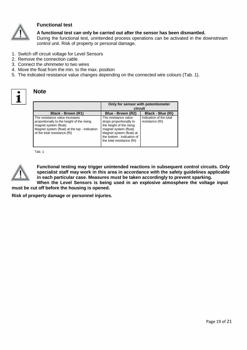
Functional test
A functional test can only be carried out after the sensor has been dismantled.
During the functional test, unintended process operations can be activated in the downstream control unit. Risk of property or personal damage.
1. Switch off circuit voltage for Level Sensors 2. Remove the connection cable 3. Connect the ohmmeter to two wires 4. Move the float from the min. to the max. position 5. The indicated resistance value changes depending on the connected wire colours (Tab. 1).
Note
Tab. 1
Functional testing may trigger unintended reactions in subsequent control circuits. Only specialist staff may work in this area in accordance with the safety guidelines applicable in each particular case. Measures must be taken accordingly to prevent sparking. When the Level Sensors is being used in an explosive atmosphere the voltage input
must be cut off before the housing is opened.
Risk of property damage or personnel injuries.
Only for sensor with potentiometer circuit
Black - Brown (R1) Blue - Brown (R2) Black - Blue (Ri) The resistance value increases proportionally to the height of the rising magnet system (float). Magnet system (float) at the top - indication of the total resistance (Ri)
The resistance value drops proportionally to the height of the rising magnet system (float). Magnet system (float) at the bottom - indication of the total resistance (Ri)
Indication of the total resistance (Ri)
Page 20 of 21
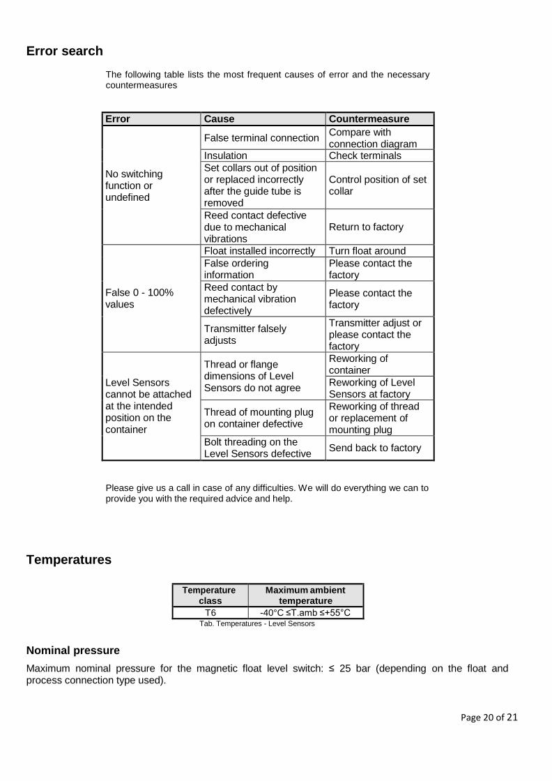
Error search
The following table lists the most frequent causes of error and the necessary countermeasures
Error Cause Countermeasure
No switching function or undefined
False terminal connection Compare with connection diagram
Insulation Check terminals
Set collars out of position or replaced incorrectly after the guide tube is removed
Control position of set collar
Reed contact defective due to mechanical vibrations
Return to factory
False 0 - 100% values
Float installed incorrectly Turn float around
False ordering information
Please contact the factory
Reed contact by mechanical vibration defectively
Please contact the factory
Transmitter falsely adjusts
Transmitter adjust or please contact the factory
Level Sensors cannot be attached at the intended position on the container
Thread or flange dimensions of Level Sensors do not agree
Reworking of container
Reworking of Level Sensors at factory
Thread of mounting plug on container defective
Reworking of thread or replacement of mounting plug
Bolt threading on the Level Sensors defective
Send back to factory
Please give us a call in case of any difficulties. We will do everything we can to provide you with the required advice and help.
Temperatures
Temperature class
Maximum ambient temperature
T6 -40°C ≤T.amb ≤+55°C Tab. Temperatures - Level Sensors
Nominal pressure
Maximum nominal pressure for the magnetic float level switch: ≤ 25 bar (depending on the float and process connection type used).
Seite 21 von 21
KSR KUEBLER Niveau-Messtechnik AG
Heinrich-Kuebler-Platz 1
D-69439 Zwingenberg am Neckar
Tel:[+49] 06263 870
Fax:[+49] 06263/87-99
e-Mail: [email protected]
www.ksr-kuebler.com