Kit de Emergência 4 em 1 -...
24
Manual do Usuário Kit de Emergência 4 em 1
Transcript of Kit de Emergência 4 em 1 -...

Manual do Usuário Kit de Emergência 4 em 1

3
Índice | Português
1. Introdução .................................................................................................................................. 5 2. Características ............................................................................................................................ 7 3. Instruções ................................................................................................................................... 8 3.1 Precauções ............................................................................................................................. 9 3.2 Recarga ................................................................................................................................... 9 3.3 Operação ..............................................................................................................................10 3.3.1 Utilizando como Fonte 12 Vc.c. ..........................................................................................10 3.2.2 Utilizando o Auxiliador de Partida ........................................................................................10 3.3.2 Operação do Compressor ..................................................................................................11 3.3.3 Substituição da Bateria .....................................................................................................11
Index | English
1.Introduction ...............................................................................................................................15 2. Features ...................................................................................................................................17 3. Instructions ..............................................................................................................................17 3.1 Important Safety Instructions ..................................................................................................17 3.2. Usage Instructions ................................................................................................................18 3.3. Cautions ...............................................................................................................................18 3.4. Recharging ...........................................................................................................................19 3.5 Operation ..............................................................................................................................20 3.5.1. To use your Power Booster as a 12V DC/DC power source: ...............................................20 3.5.2 Jump Starting ...................................................................................................................20 3.5.3 Compressor operation .......................................................................................................21 3.6. Battery replacement .............................................................................................................21 4. Environmental Message ............................................................................................................23

5
1. Introdução
Obrigado por adquirir um produto da marca Multilaser. O Auxiliador de partida 4x1 é portátil e especialmente desenhado para que você desfrute da conveniência e facilidade de ter em suas mãos quatro funções principais em um único produto. O Auxiliador de Partida 4x1 é uma unidade auxiliar de partida portátil e compacta para automóveis, motos e pequenas embarcações. Ele também pode ser usado como uma unidade portátil de energia 12 Vc.c., além de possuir a função de compressor de ar e luz de emergência de LED.
Leia este guia do usuário com atenção antes de utilizá-lo.
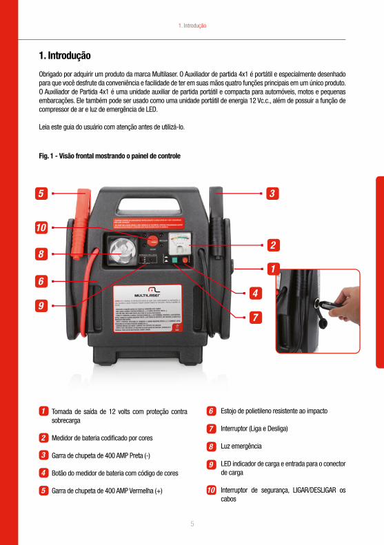
Fig. 1 - Visão frontal mostrando o painel de controle
1. Introdução
1
2
35
6
8
10
94
7
1
2
3
4
5
6
7
8
9
10
Tomada de saída de 12 volts com proteção contra sobrecarga
Medidor de bateria codificado por cores
Garra de chupeta de 400 AMP Preta (-)
Botão do medidor de bateria com código de cores
Garra de chupeta de 400 AMP Vermelha (+)
Estojo de polietileno resistente ao impacto
Interruptor (Liga e Desliga)
Luz emergência
LED indicador de carga e entrada para o conector de carga
Interruptor de segurança, LIGAR/DESLIGAR os cabos
6
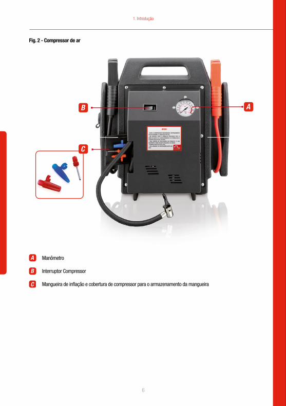
Fig. 2 - Compressor de ar
C
AB
Manômetro
Interruptor Compressor
Mangueira de inflação e cobertura de compressor para o armazenamento da mangueira
A
B
C
1. Introdução

7
2. Características
• Potencia de partida de 250 A e pico de 600 A.
• Dá partida em carros, caminhões, veículos de passeio e barcos sem a necessidade de um segundo veículo ou cabos de alimentação.
• A tomada para acendedor de cigarros de 12 Vc.c. com proteção contra sobrecarga fornece energia para utilitários e aparelhos que em geral se conectam a uma tomada para acendedor de cigarros de 12V de veículos ou barcos.
• Fornece até 50 horas de alimentação Vc.c. quando é usado como tomada de 12 Vc.c..
• Permite aparelhos de 12V a ser usados em locais remotos e/ou em caso de emergência quando a alimentação conven-cional não está disponível.
• Operação automática com proteção contra curto-circuito.
• Bateria selada e resistente, sem necessidade de manutenção.
• Este sistema pode ser armazenado sem risco de vazamento de ácido.
• O cabo que acompanha as garras para chupeta são do tipo industrial, resistente, podendo transportar mais corrente do que as unidades semelhantes.
• O medidor de bateria é codificado por cores e de fácil leitura.
• O cabo de alimentação Vc.c. permite o recarregamento em tomada para acendedor de cigarros de 12 Vc.c..
• O estojo de alto impacto moldado é forte e durável.
• Possui luz embutida para conserto de veículos na estrada em situações de emergência sem necessidade de alimentação convencional.
2. Características
8
3. Instruções
3. Instruções
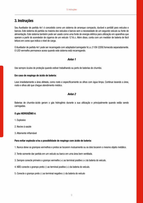
Seu Auxiliador de partida 4x1 é concebido como um sistema de arranque compacto, durável e portátil para veículos e barcos. Este sistema dá partida na maioria dos veículos e barcos sem a necessidade de um segundo veículo ou fonte de alimentação. Este sistema também pode ser usado como uma fonte de energia elétrica para utilização em aparelhos que operam a partir do acendedor de cigarros de um veículo 12 Vc.c. Além disso, conta com um medidor de bateria de fácil leitura em cores que indica o nível de carga.
O Auxiliador de partida 4x1 pode ser recarregado com adaptador/carregador Vc.a. (110V-220V) fornecido separadamente. O LED vermelho permanece aceso quando este sistema está recarregando.
Aviso 1
Use sempre óculos de proteção quando estiver trabalhando ou perto de baterias de chumbo.
Em caso de respingo de ácido de bateria:
Lave imediatamente a área afetada, como rosto e especificamente os olhos com água limpa. Continue lavando a área, rosto e olhos até que chegue atendimento médico.
Aviso 2
Baterias de chumbo-ácido geram o gás hidrogênio durante a sua utilização e principalmente quando estão sendo carregadas.
O gás HIDROGÊNIO é:
1. Explosivo
2. Nocivo à saúde
3. Altamente inflamável
Para evitar explosão e/ou a possibilidade de respingo com ácido de bateria:
1. Nunca deixe os grampos vermelhos e pretos se tocarem mutuamente ou os dois tocarem o mesmo objeto metálico. 2. Tente somente dar partida em um veículo ou barco em uma área bem ventilada.
3. Sempre conecte primeiro o grampo vermelho (+) ao terminal positivo (+) da bateria do veículo.
4. NÃO conecte o grampo preto (-) ao terminal positivo (+) da bateria do veículo.
5. Conecte o grampo preto (-) ao terminal negativo (-) da bateria do veículo
9
3. Instruções
3.1 Precauções
1. Para evitar possíveis danos que possam encurtar a vida útil da unidade, proteja essa unidade da luz solar direta, calor direto e/ou umidade.
2. Este sistema é projetado para ser usado somente em veículos ou barcos com sistemas elétricos de 12 volts.
3. Este sistema não é projetado para ser usado como substituto de bateria de um veículo.
3.2 Recarga
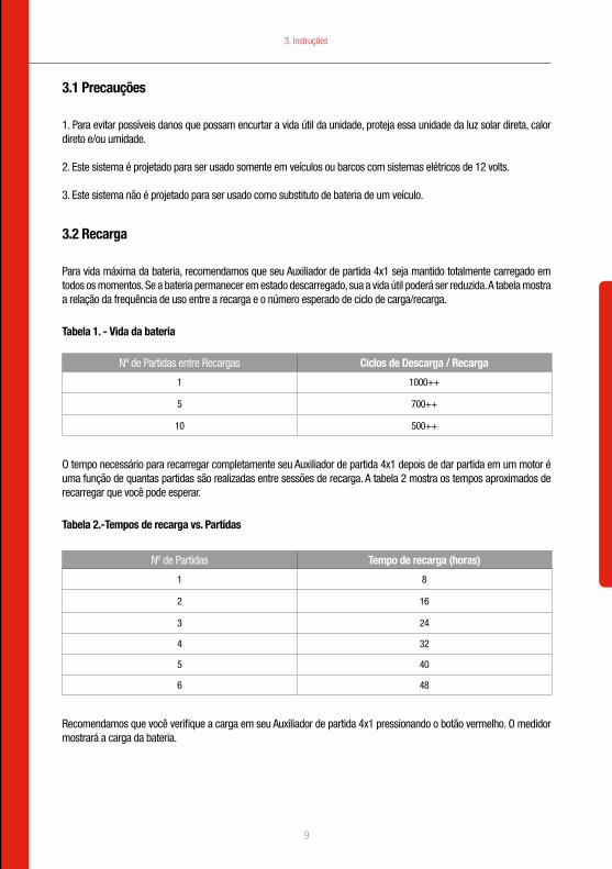
Para vida máxima da bateria, recomendamos que seu Auxiliador de partida 4x1 seja mantido totalmente carregado em todos os momentos. Se a bateria permanecer em estado descarregado, sua a vida útil poderá ser reduzida. A tabela mostra a relação da frequência de uso entre a recarga e o número esperado de ciclo de carga/recarga.
Tabela 1. - Vida da bateria
Nº de Partidas entre Recargas Ciclos de Descarga / Recarga
1 1000++
5 700++
10 500++
O tempo necessário para recarregar completamente seu Auxiliador de partida 4x1 depois de dar partida em um motor é uma função de quantas partidas são realizadas entre sessões de recarga. A tabela 2 mostra os tempos aproximados de recarregar que você pode esperar.
Tabela 2.-Tempos de recarga vs. Partidas
Nº de Partidas Tempo de recarga (horas)
1 8
2 16
3 24
4 32
5 40
6 48
Recomendamos que você verifique a carga em seu Auxiliador de partida 4x1 pressionando o botão vermelho. O medidor mostrará a carga da bateria.
10
Carga com adaptador/carregador Vc.a.:
Conecte o adaptador/carregador a uma tomada Vc.a. e coloque a outra extremidade na entrada do carregador que está ao lado do LED indicador de carga (Nº 11, ver figura 1) no painel frontal do seu Auxiliador de Partida 4x1 até que o medidor da bateria indique “carga completa” (14 a 15 CC).
Carga com cabo de alimentação 12V CC/CC
Insira o conector para acendedor de cigarros do adaptador/carregador de 12V CC/CC (nº 8, ver figura 1) em um receptáculo do acendedor de cigarros de 12V CC (em seu veículo ou barco) e coloque a outra extremidade (saída) no receptáculo (ao lado do LED de carga CC nº 11, ver figura 1) no painel frontal do seu Auxiliador de Patida até que o medidor da bateria indique “carga completa” (14 a 15 Vc.c.)
3.3 Operação
3.3.1 Utilizando como Fonte 12 Vc.c.
Retire a tampa da entrada do acendedor de cigarros de 12 Vc.c. (ver nº 1 da figura 1)
Insira o conector para acendedor de cigarros de 12 Vc.c. do aparelho na entrada do acendedor de cigarros de 12 Vc.c. ao lado do seu Auxiliador de partida 4x1.
Obs: A chave ON-OFF deve permanecer na posição OFF.
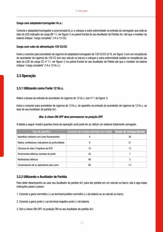
A tabela a seguir mostra quantas horas de operação você pode ter ao utilizar um sistema totalmente carregado.
Tipo de aparelho Consumo de energia estimado (em watts) Tempo de recarga (horas)
Aparelhos celulares com luzes fluorescentes 4 30
Rádios, ventiladores, indicadores de profundidade 9 21
Câmaras de vídeo, Projetores de VCR 15 12
Ferramentas elétricas, bombas de porão 24 7
Resfriadores elétricos 48 3
Compressores de ar, aspiradores para carro 80 1.5
3.2.2 Utilizando o Auxiliador de Partida
Para obter desempenho ao usar seu Auxiliador de partida 4x1 para dar partida em um veículo ou barco, leia e siga estas instruções passo a passo:
1. Conecte a garra vermelha (+) ao terminal positivo vermelho (+) da bateria ou ao veículo ou barco.
2. Conecte a garra preto (-) ao terminal negativo preto (-) da bateria.
3. Gire a chave ON-OFF, na posição ON no seu Auxiliador de partida 4x1.
3. Instruções

11
4. Aguarde um minuto ou dois.
5. Dê partida no veículo
6. Se o motor do veículo ou barco não der partida, aguarde pelo menos 3 minutos antes de tentar novamente.
7. Após o motor estar funcionando, desconecte primeiro a garra preta colocando-a na sua posição original.
8. Desconecte a garra vermelha e volte-a a sua posição original.
9. Gire a chave ON-OFF na posição OFF.
10. Assim que possível recarregue a bateria da Maleta Auxiliar de Partida, verificando sua carga no voltímetro.
Em hipótese alguma permita que os grampos vermelho e preto se toquem ou toquem um condutor comum
3.3.2 Operação do Compressor
Atenção: Deixe o compressor funcionar continuamente por somente 10 minutos por vez. Desligue-o por 10 minutos antes de usá-lo novamente de modo que o compressor possa esfriar.
1. Certifique-se de que a chave de alimentação principal na parte frontal está na posição “ON”.
2. Para encher o pneu use o adaptador universal que fica permanentemente conectado à mangueira de ar. Ou, coloque um dos três adaptadores “acessórios” que acompanham seu produto (nº C, ver figura 2) no sistema de válvula do pneu. Pressione a alavanca do adaptador para baixo para travar o sistema de válvula.
3. Para encher bolas de couro, dispositivos de flutuação etc. use um dos adaptadores plásticos.
4. Verifique o manômetro (nº A, ver figura 2) para determinar a pressão desejada. 5. Ligue a chave de alimentação (nº B, ver figura 2)
6. Quando a pressão desejada é alcançada, desligue a chave do compressor (nº B, ver figura 2)
7. Remova o adaptador (nº C, ver figura 2) do pneu ou outro item que esteja sendo inflado.
3.3.3 Substituição da bateria
A Figura 3 mostra uma vista traseira do seu Auxiliador de partida 4x1 com tampa e oito parafusos removidos. Para substituir a bateria, siga estes passos.
3. Instruções
12
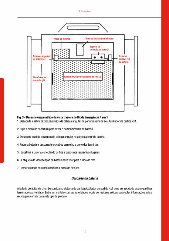
Fig. 3 - Desenho esquemático da vista traseira do Kit de Emergência 4 em 11. Desaperte e retire os oito parafusos de cabeça angular na parte traseira de seu Auxiliador de partida 4x1.
2. Erga a placa de cobertura para expor o compartimento da bateria.
3. Desaperte os dois parafusos de cabeça angular na parte superior da bateria.
4. Retire a bateria e desconecte os cabos vermelho e preto dos terminais.
5. Substitua a bateria conectando os fios e cabos nos respectivos lugares.
6. A etiqueta de identificação da bateria deve ficar para o lado de fora.
7. Tomar cuidado para não danificar a placa do circuito.
Descarte da bateria
A bateria de ácido de chumbo contida no sistema de partida Auxiliador de partida 4x1 deve ser reciclada assim que tiver terminado sua validade. Entre em contato com as autoridades locais de resíduos sólidas para obter informações sobre reciclagem correta para este tipo de produto.
Placa de circuito
Terminal negativo da bateria (-)
Almofadas deborracha (2)
Terminalpositivo (+) da bateria
Chave de fechamento térmico
Bateria de ácido de chumbo de 12V CC
Suporte de retenção de bateria
3. Instruções

13
Aviso
NÃO descarte a bateria no fogo. Isso pode resultar em explosãoAntes de descartar a bateria, proteja os terminais expostos com fita isolante para evitar curto-circuito (curto-circuito pode resultar em lesões ou incêndio). NÃO exponha a bateria ao fogo ou calor intenso, pois pode explodir.
Substituição da luz de emergência
1. Aperte delicadamente as laterais da moldura da lente de luz de emergência e remova a lente e a moldura.
2. Desrosqueie e retire a lâmpada queimada.
3. Substitua por uma lâmpada nova.
4. Encaixe a lente e a moldura no lugar.
Aviso
Este aparelho não se destina à utilização por pessoas (inclusive crianças) com capacidades físicas, sensoriais ou mentais reduzidas, ou por pessoas com falta de experiência e conhecimento, a menos que tenham recebido instruções referentes à utilização do aparelho ou estejam sob a supervisão de uma pessoa responsável pela sua segurança.
Recomenda-se que as crianças sejam vigiadas para assegurar que elas não estejam brincando com o aparelho.
3. Instruções

English

15
1.Introduction
The power booster is designed as a compact, durable and portable jump start system for vehicle and boats. This self-contained system will start most vehicles and boats without the need for a host vehicle or 127V AC power supply. This system can also be used as a safe, portable source of 12 DC electric power in remote location and emergencies. Keep these instructions for future reference.
Figure 1. Front view showing control panel
1
2
3
4
5
6
7
8
9
10
1. Introduction
12 Volt output socket with overload protection
Color-coded battery meter
Heavy-duty 400 AMP booster clamps)
The button of color-coted battery meter
Heavy-duty industrial welding clamps
Impact resistant polyethylene case
ON/OFF LIGHT
Emergency light
DC charging LED and receptacle for charging plug
Safe switch, ON/OFF the cables
1
2
35
6
8
10
94
7
16
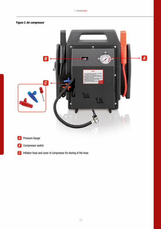
Figure 2. Air compressor
C
AB
Pressure Gauge
Compressor switch
Inflation hose and cover of compressor for storing of the hose
A
B
C
1. Introduction
17
2. Features
• 600Amps peak/250 Amps booster starting power.
• Starts cars, trucks, recreation vehicles and boats without the need of a host vehicle or AC power cords.
• 12 V cigarette lighter socket with overload protection provides power for utilities and appliances that usually plug into a vehicle or boat 12V cigarette lighter socket.
• Provides up to 50-hours of DC power when use with 12 DC socket.
• Allows 12V appliance to be used in remote sites and/or in emergency when commercial power is not available.
• Solid-state, automatic operation and circuit protection.
• Maintenance-free, 7AH battery.
• This system can be stored without risking acid leakage.
• 9. Heavy-duty industrial type welding cable can carry more amperage than similar units.
• Battery condition meter is color coded and easy to read.
• DC power cord allows recharging from 12V DC cigarette lighter socket.
• Molded high-impact case is tough and durable.
• Has a built-in light for roadside vehicle repair for emergency situation away from commercial power.
3. Instructions
3.1 Important Safety Instructions
• This is a domestic electrical product, which must only be used for its intended purpose, in accordance with these Instructions. This product should never be used in a commercial environment.
• Check the rating plate to ensure that the correct input voltage is being supplied to the product.
• Always switch the product off and remove the plug from the wall socket when not in use and before cleaning or changing accessories.
• Most domestic appliances must be attended at all times when in use. Never leave this product unattended when connected to the mains supply unless instructed to do so by these instructions.
• Always ensure the product is switched off before connecting it to the mains supply.
• Never reach for an electrical product that has fallen into water. To do so will result in an electric shock. Switch off the power at the wall socket and disconnect the plug before attempting to remove it from the water. After removing, never attempt to re-connect the product until it has fully dried and been tested and approved by a qualified person.
2. Features / 3. Instructions

18
• Domestic electrical products are not designed for use by children!. Any child using a domestic electrical product should be closely supervised by a responsible adult to ensure all instructions and safety precautions are adhered to.
• Never allow the mains cable to come into contact with a heat source, water or any other liquid. Ensure sharp objects like knives etc are never used close to a mains cable when the product is in use.
• Never allow the cable of an electrical product to drape over the edge of a work surface where it could be pulled by a small child. Always check the
3.2. Usage Instructions
The power booster has an easy to read, color-coded battery meter that indicates charge level. A 12V DC cigarette lighter-type socket is provided for use with appliance that would operate from a vehicle cigarette lighter. This allows maximum portability and utility when a mains plug is not available. Your jump starter can also be recharged with the included 230V AC adapter/charger. A covered cigarette lighter type 12V DC socket is also provided. The red LED will illuminate when the battery is recharging.
Warning 1
Always wear eye protection when working on or around lead-acid batteries. If splashed with battery acid immediately wash effected area such as face and particularly the eyes with clean water. Continue washing the affected area and face until medical help arrives.
Warning 2
Lead-acid batteries generate hydrogen gas during normal operation. More gas is generated when the battery is charging. Hydrogen gas is:
1. Explosive2. Poisonous to breathe3. Highly flammable
To avoid explosion and/or the possibility of being splashed with battery acid:
1. Never allow the red and black clamps to touch each other nor to both touch the same metal object.2. Only attempt to jump start a vehicle or boat in a well ventilated area.3. Always connect the red (+) clamp to the positive (+) battery terminal of vehicle4. Do not connect the black (-) clamp to a non-moving metal part on the engine.
3.3. Cautions
• To avoid possible damage that may shorten the unit’s working life, protect this unit from direct sunlight, direct heat and/or moisture.
• This system is designed to be used only on vehicle or boats with 12-Volt electric systems.
• This system is not designed to be used as a replacement for a vehicle’s battery.
3. Instructions

19
• Air compressor caution: run compressor only for 10 minutes as a time continuously. Then leave off for 10 minutes before using again so that compressor can cool.
3.4. Recharging
For maximum battery life,we recommend that your power booster be kept fully charged at all times if the battery is allowed to remain in a discharged state. battery life maybe shortened. Table shows the relationship of the frequency of use between recharging and the expected number of charge/recharge cycle.
This unit MUST be charged every 3 months, whether use or not. In each charging, the time is no morn than 36hours.
And please, keep it at the normal condition. DO NOT hit.
Battery life
Number of jump-starts between recharging Discharge and recharge cycles
1 1000++
5 700++
10 500++
Battery Recharging Tips
The time required to fully recharge your power booster after jump-starting an engine is a function of how many jump starts are performed between recharging sessions. Table 2 shows the approximate recharging times you expect.
Number of jump-starts Recharging Time (in hours)
1 8
2 16
3 24
4 32
5 40
6 48
To check the battery charge, press the red button next to the volt meter. This will show you the battery’s internal charge level.
3. Instructions

20
AC adapter/charger charging:
Plug the Adapter/charger into an AC power outlet and put the other (output DC 12V) end into the receptacle(beside DC charging LED(No.11,see figure 1)on the front panel of your power booster until the battery meter shows full(14 to 15 DC)
12V DC/DC power cord charging
Insert the cigarette lighter plug of the 12V DC/DC adapter/charger(No.8,see figure 1) into an 12V DC cigarette lighter receptacle(on your vehicle or boat )and put the other (output )end into the receptacle (beside DC charging LED No.11,see figure 1)on the front panel of your power booster until the battery meter shows full (14 to 15V DC )
3.5 Operation 3.5.1. To use your power booster as a 12V DC/DC power source:
• Life up the cover of 12V DC cigarette lighter receptacle (see No.1 of figure 1)• Insert the 12V DC cigarette lighter plug from the appliance into the 12V DC cigarette lighter receptacle on the side of your booster
The following table will give you an idea of what operation time you can expect when starting from a fully charged system.
Appliance type Estimated power comsumption (in wats) Estimated usage time (in hours)
Fluorescent lights cell phones 4 30
Radios, fans, depth finders 9 21
Camcorders, VCR’s spotlights 15 12
Electric tools ,bilge pumps 24 7
Electric coolers 48 3
Air compressors ,car vacuums 80 1.5
3.5.2 Jump Starting
For performance when using your power booster to jump start a vehicle or boat, please read and follow these step by step instructions:
1. Connect the red (+) alligator clamp to the red (+) positive battery terminal or the vehicle or boat.
2. Connect the black (-) alligator clamp to a non-moving metal part of the engine, NOT to the (-) negative battery terminal.
3. Wait a minute or two
4. Turn on the Power Switch then switch the vehicle or boat engine ignition to “start” for no more than 5 to 6 seconds.
5. If the vehicle or boat engine does not start, wait at least 3-minutes before trying again.
6. Once the engine is running, disconnect the black (-) clamp first and return this cable to its stored position on the power booster.
3. Instructions

21
7. Disconnect the red (+) clamp and return this cable to its stored position on the power booster.
8. As soon as possible connect your power booster system to the AC adapter. charge and recharge.
Under no circumstances allow the red and black clamps to touch each other or a common contact
3.5.3 Compressor operation
Caution: Run compressor only for 10 minutes at a time continuously. Then leave off for 10 minutes before using again so that compressor can cool.
1. Be sure main power switch on front face is in the “ON” position.
2. For tire inflation use the universal adapter that is attached permanently to the air hose. Place this adapter (No. C, see figure 2) onto the tire valve system, press the adapter lever down to lock onto the valve system.
3. For inflation of leather balls, flotation devices, etc., use one of the plastic nozzles.
4. Check pressure gauge (No. A, see figure 2), determine the desired pressure.
5. Turn on power switch (No. B, see figure 2)
6. When the desired pressure is reached turn the compressor switch (No. B, see figure 2) off.
7. Remove the adapter(No. C, see figure 2) from tire or other item being inflated.
3.6. Battery replacement
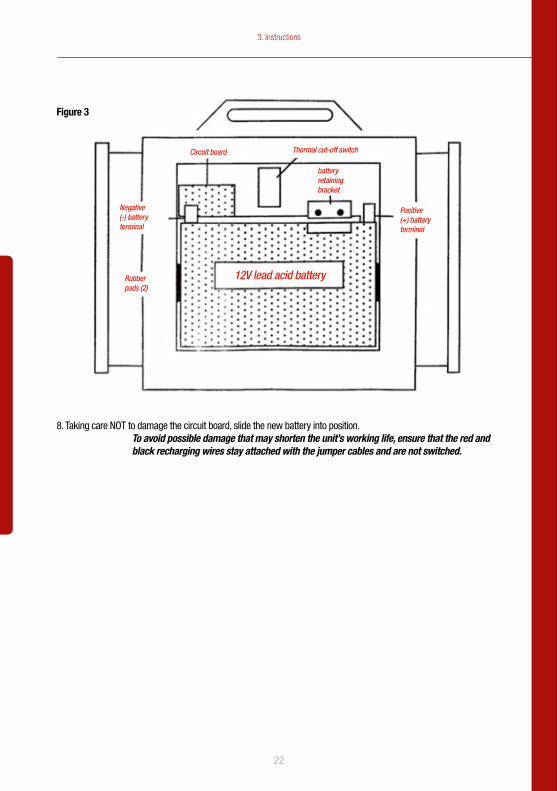
Figure 3 - Shows a back view of your power booster with cover and eight screws removed. To replace the battery follow these steps.
1. Unscrew and remove the eight cross-headed screws at the back of your power booster.
2. Lift off the cover plate to expose the battery compartment.
3. Unscrew the two cross-headed screws at the top of the battery.
4. Lift the battery out the battery compartment.
5. Detach cables and the red and black recharging wires from the battery terminals.
6. Ensure that the replacement battery is oriented with the label out.
7. Ensure that the red cable and red recharging wire are attached to the positive (+) battery terminal (also marked with red). Attach cables and the recharging wires to the battery terminals.
3. Instructions
22
8. Taking care NOT to damage the circuit board, slide the new battery into position.To avoid possible damage that may shorten the unit’s working life, ensure that the red and black recharging wires stay attached with the jumper cables and are not switched.
Positive (+) battery terminal
battery retaining bracket
Thermal cut-off switchCircuit board
Negative (-) battery terminal
Rubber pads (2)
12V lead acid battery
Figure 3
3. Instructions
23
4. Environmental Message
The crossed out wheel bin symbol on this item indicates that this appliance needs to be disposed of in an environmentally friendly way when it becomes of no further use or has worn out. Contact your local authority for details of where to take the item for re-cycling.
Warning
Do NOT dispose of the battery in an open flame as this may result in an explosion.
Before disposing of the battery, protect exposed terminals with heavy-duty electrical tape to prevent shorting (shorting can result in injury or fire). Do NOT expose battery to fire or intense heat as it may explode.
Emergency light-bulb replacement
1. Gently squeeze the sides of the emergency light lens bezel together and remove the lens and bezel.2. Unscrew and remove the burned out bulb.3. Replace with a new bulb.4. Snap the lens and bezel in place.
Battery disposal
The lead acid battery contained in the power booster jump start system should be recycled once it has expired. Please contact your local solid waste authority for recycling information.
4. Environmental Message

24
www.multilaser.com.br