
Ntd 3.34 - Chave Seccionadora Tripolar a Sf6 Com Transferncia Automtica

ARTES
KO C O S - T H E T E C H N O L O G Y G R O U P | W H E R E P R E C I S I O N M E E T S Q UA L I T Y
Automatic Relay Test Systems460|560
[ ENG ]K O C O S M E S S T E C H N I K A G

2
CONTENT S
ARTES Automatic Relay Test Systems.................................................................................................................3
Product overview .............................................................................................................................................................4
Technical data ARTES 460|560 ......................................................................................................................................5
Applications ...........................................................................................................................................................................6
System description .........................................................................................................................................................7
Current and voltage amplifiers ........................................................................................................................................7
Equipment and handling ................................................................................................................................................10
The ARTES testing software ...................................................................................................................................14
ARTES test monitors ..........................................................................................................................................................18
Test monitor overview ...................................................................................................................................................... 29
Software modules and packages ................................................................................................................................. 29
Options and accessories .......................................................................................................................................... 30
Device options .................................................................................................................................................................... 30
Cable sets ............................................................................................................................................................................ 30
Adapters ................................................................................................................................................................................31
Wrap-around bags and carrying cases ....................................................................................................................... 32
Training courses and seminars ............................................................................................................................ 33
Specifications ARTES 460|560 .............................................................................................................................. 34

3
ARTESARTESAutomAtic RelAy test systems The purpose of power system protection is to use accurate and reliable protection devices to detect faults promptly and without fail and to minimize impairments to the power sup-ply by selectively switching off faulted sections of the system.
The use of suitable protection devices can significantly im-prove the safety and reliability of complex electrical power systems and installations. Regular testing is the only way to ensure that these protection devices function correctly throughout their operational life.
More than 20 years of experience in developing and manu-facturing automatic relay test systems have gone into cre-ating the third generation of ARTES test instruments. Back in 1996, KoCoS was the first company to present Windows-based testing software for controlling and operating test equipment and the company continues to play a pioneering role in the design of clearly structured and ergonomic user interfaces today.

4
ARTESARTESPRoduct oveRviewARTES 460|560 test systems are practical solutions which can cope with just about any relay testing task.
ARTES 460Compact test system for three-phase tests, can be used as a uni-versal tool for testing digital protection relays.Article number 00001276
ARTES 560Compact test system for three-phase tests with a particularly powerful current amplifier for testing digital and self-powered protection relays.Article number 00001279
5
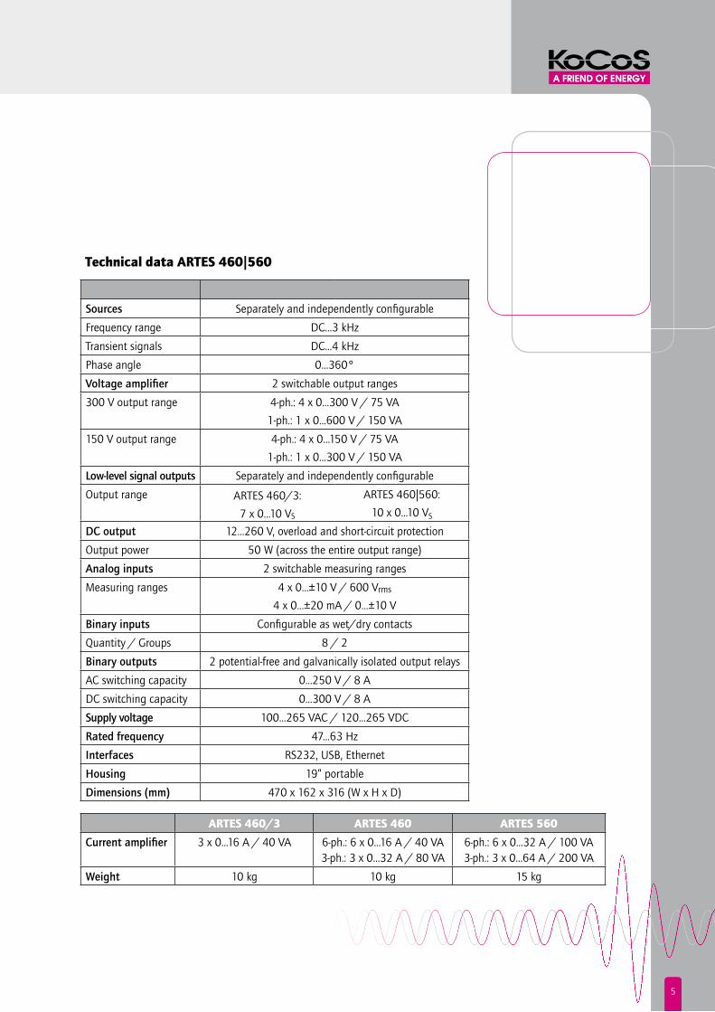
Technical data ARTES 460|560
sources Separately and independently configurable
Frequency range DC...3 kHz
Transient signals DC...4 kHz
Phase angle 0...360°
voltage amplifier 2 switchable output ranges
300 V output range 4-ph.: 4 x 0...300 V / 75 VA
1-ph.: 1 x 0...600 V / 150 VA
150 V output range 4-ph.: 4 x 0...150 V / 75 VA
1-ph.: 1 x 0...300 V / 150 VA
low-level signal outputs Separately and independently configurable
Output range ARTES 460/3:
7 x 0...10 VS
ARTES 460|560:
10 x 0...10 VSdc output 12...260 V, overload and short-circuit protection
Output power 50 W (across the entire output range)
Analog inputs 2 switchable measuring ranges
Measuring ranges 4 x 0…±10 V / 600 Vrms4 x 0…±20 mA / 0...±10 V
Binary inputs Configurable as wet/dry contacts
Quantity / Groups 8 / 2
Binary outputs 2 potential-free and galvanically isolated output relays
AC switching capacity 0...250 V / 8 A
DC switching capacity 0...300 V / 8 A
supply voltage 100...265 VAC / 120...265 VDC
Rated frequency 47...63 Hz
interfaces RS232, USB, Ethernet
Housing 19“ portable
dimensions (mm) 470 x 162 x 316 (W x H x D)
ARTES 460/3 ARTES 460 ARTES 560
current amplifier 3 x 0...16 A / 40 VA 6-ph.: 6 x 0...16 A / 40 VA3-ph.: 3 x 0...32 A / 80 VA
6-ph.: 6 x 0...32 A / 100 VA3-ph.: 3 x 0...64 A / 200 VA
weight 10 kg 10 kg 15 kg
6
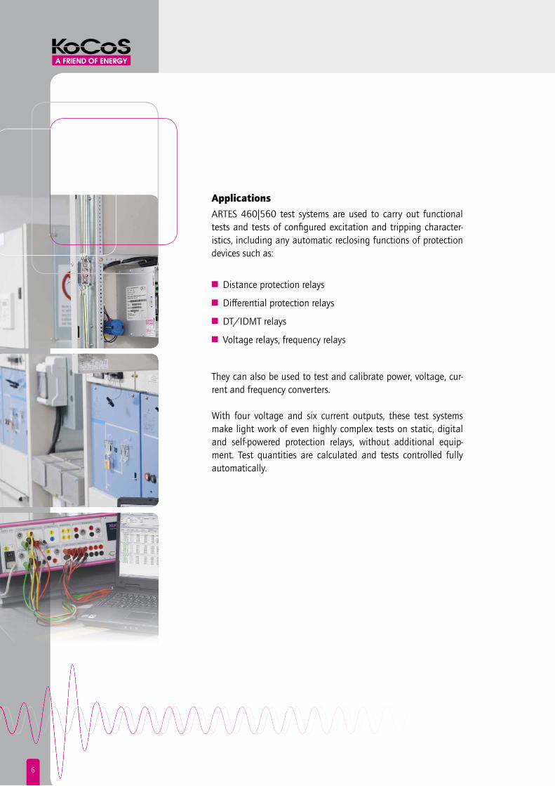
ApplicationsARTES 460|560 test systems are used to carry out functional tests and tests of configured excitation and tripping character-istics, including any automatic reclosing functions of protection devices such as:
n Distance protection relays
n Differential protection relays
n DT/IDMT relays
n Voltage relays, frequency relays
They can also be used to test and calibrate power, voltage, cur-rent and frequency converters.
With four voltage and six current outputs, these test systems make light work of even highly complex tests on static, digital and self-powered protection relays, without additional equip-ment. Test quantities are calculated and tests controlled fully automatically.

7
system descRiPtion
The ARTES 460|560 test instruments have been specially devel-oped for harsh transport and operational conditions. The use of state-of-the-art technologies coupled with a high level of system integration has made it possible to accommodate this compact, lightweight test instrument in a portable 19“ housing.Because of the very effective cooling system and automatic fan control, the test instruments go largely unnoticed during opera-tion.
Current and voltage amplifiers
ARTES 460|560 test systems have four voltage outputs and six current outputs. Many tasks in protection relay testing do not require more than three current outputs. The ARTES 460/3 test system, which is equipped with three instead of six current out-puts, is available as a cost-effective alternative for this situation. The test quantities are monitored constantly by means of an internal feedback measurement of the output signals.
test currents of up to 3 x 64 A with parallel operation
In order to provide higher test currents, the current amplifiers of the ARTES 560 can be operated in parallel. Because there are 6 current outputs, up to 3 x 64 A can be provided for 3-phase applications.

8
High output power with low test currents
A supply voltage of up to 30 V is available for the ARTES 560 current amplifiers. Even with low test currents, the current am-plifiers can provide a high compliance voltage and thus a high level of output power.
constant output signals for changing burdens
Even if the burden of the device under test changes during out-put, constant output signals with very high accuracy are guar-anteed. Synthetic signal genera- tion with a powerful signal processor, internal feed-back measurements of the output signals in real time and ultra-fast regulation of the amplifiers make this possible and ensure that the signals correspond ex-actly to the desired values during output.

9
wide frequency range for the output of transient signals
The fully electronic amplifiers of ARTES 460|560 do not feature transformers in the outputs, so it is possible to generate output signals with a wide frequency range of several kHz. In addition to self-generated signals, records from fault recorder systems can also be output as transient signals.
immunity to disturbances in the power supply
Powerful, wide-range switching mode power supplies safeguard the power supply to the ARTES amplifiers and ensure fault-free operation and constant output signals. Changes to the output quantities are completely eliminated, including inaccuracies and errors resulting from fluctuations in the supply voltage.

10
Equipment and handling ARTES 460|560 test systems are the compact and universal so-lution for testing all types of protection relays. The built-in con-trol panel, light weight and low noise level make this robust test system equally suitable for use on site and in the lab.
stand-alone operation with 3.5“ touch screen
ARTES 460|560 test instruments can be operated and controlled with the aid of a PC and the ARTES testing software or with the built-in control panel. The control panel features a high-resolution, resistive 3.5“ touch screen and four function keys.The Windows-based user interface enables the test instrument to be operated simply and intuitively. All the settings required for a test are displayed clearly on the large graph-ical display and can be edited directly without lengthy menu navigation.
A wide range of communication interfaces
As well as a serial interface and a passive USB interface, ARTES 460|560 systems also feature an active USB interface, specially provided for data transmission via USB storage media, which can be used for firmware updates, for example.In addition, the Ethernet interface allows direct integration in any network as well as tests in IEC 61850 environments.
11
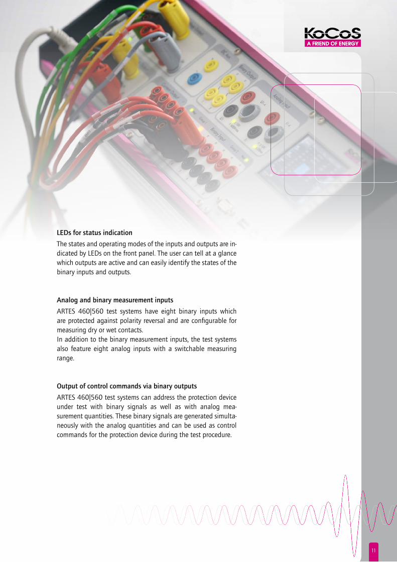
leds for status indication
The states and operating modes of the inputs and outputs are in-dicated by LEDs on the front panel. The user can tell at a glance which outputs are active and can easily identify the states of the binary inputs and outputs.
Analog and binary measurement inputs
ARTES 460|560 test systems have eight binary inputs which are protected against polarity reversal and are configurable for measuring dry or wet contacts.In addition to the binary measurement inputs, the test systems also feature eight analog inputs with a switchable measuring range.
output of control commands via binary outputs
ARTES 460|560 test systems can address the protection device under test with binary signals as well as with analog mea- surement quantities. These binary signals are generated simulta-neously with the analog quantities and can be used as control commands for the protection device during the test procedure.

12
testing protection devices with low-level signal inputs
Special low-level outputs with very high accuracy make it possi-ble to test protection devices with low-level signal inputs as well. The behaviour of various different sensors, such as Rogowski coils, is reproduced precisely.
separate auxiliary power supply
ARTES 460|560 test systems have a separate auxiliary power supply as standard equipment. The auxiliary voltage can be used to supply the test object, for example. The range is from 12 to 260 VDC.
operation in a vertical position
All the connections required for linking up to the device under test can be found on the front panel where they are arranged ergonomically and are easily accessible. The power supply and the external interfaces are also located on the front panel. ARTES 460|560 test systems can be stood upright on the floor if necessary and still be operated comfortably.

13
ARTESARTES
can be used all over the world
The voltage and frequency range of the integrated wide-range power supply units provide a high degree of flexibility for power-ing ARTES 460|560 test instruments, allowing them to be con-nected to any national supply voltage or to DC station batteries.
software-controlled device calibration
The ARTES 460|560 test instruments have been specially designed to enable users to carry out the calibration themselves. This eliminates periods of unavailability while the test instrument is sent away and also does not involve any costs. Calibration is controlled by the software. There is no need to open the test instrument and make adjustments using potentiometers.

14
tHe ARtes testing softwARe
Featuring a Microsoft Fluent user interface and an impres- sive range of functions, the new ARTES relay testing softwarefrom KoCoS breaks new ground, securing the company‘s posi-tion at the cutting edge of the development of Windows-based testing software.
The restructured Microsoft Fluent user interface provides a wide range of new functions.The Fluent interface makes working with the ARTES testing
software both faster and more efficient. Traditional menus and toolbars have been replaced by a ribbon. The advantages of this user interface include improved handling and significant savings in time due to the use of context-specific tabs and the ease with which new users become familiar with the software.

15
clearly structured asset management based on the test object
Another noteworthy feature of the software is the asset management. The global definition of protection functions as well as the derivation and inheritance of properties from a wide variety of different type templates are what make this feature so special. In addition, it is possible to edit specific individual relay settings and test instructions as well as to make global settings for instrument transformers, earthing and the direction of the rotating field.
The asset management also allows the integration and manage-ment of external documents. This means that any information which may be required is available all the time.
graphical display of connection schemes
A graphical display of connection schemes can also be found in the ARTES testing software. This makes it easier to connect the device under test and goes a long way towards ruling out mistakes.Pre-defined models are available for the various protection func-tions and can be selected directly, making configuration much simpler.

16
individual test plans
An individual test plan can be created easily for each device under test. Individual tests can be combined to form complete device or type tests which can then be repeated any number of times under identical test conditions, making it easy to auto- mate entire test procedures.
display and evaluation of measurement results
The progress of the analog input quantities and the status sig-nals and commands of the device under test captured by ARTES are displayed time correctly in real time during tests. This infor-mation is displayed both graphically and numerically, making it possible to observe and evaluate the test procedure right away.
17
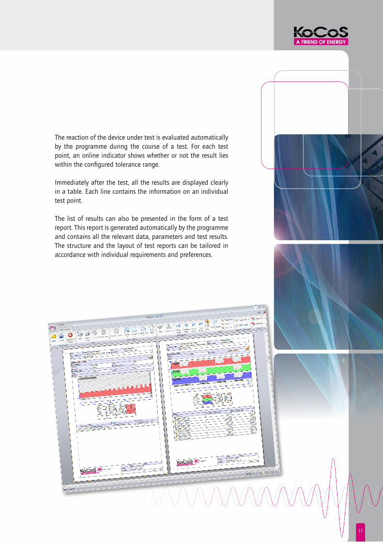
The reaction of the device under test is evaluated automatically by the programme during the course of a test. For each test point, an online indicator shows whether or not the result lies within the configured tolerance range.
Immediately after the test, all the results are displayed clearly in a table. Each line contains the information on an individual test point.
The list of results can also be presented in the form of a test report. This report is generated automatically by the programme and contains all the relevant data, parameters and test results. The structure and the layout of test reports can be tailored in accordance with individual requirements and preferences.

18
ARTES test monitorsGenerally speaking, the VD-Monitor is capable of meeting all test requirements.
The ARTES software also offers a wide range of convenient test monitors which have been specially developed for testing spe-cific protection functions. These test monitors simplify, automate and significantly speed up tests for a range of different types of relays.
vd-monitor
The VD-Monitor enables the user to test any protection function by setting the test quantities manually. As well as entering secondary values, primary values can also be used to define all the settings, so it is no longer necessary to go to the trouble of converting the quantities manually.The output signals of the current and voltage amplifiers are set entirely independently from one another as regards amplitude,
phase and frequency and are varied independently from one another during tests. In addition, the out-put signals of certain or all amplifier outputs can also be ramp ascending or descending within the configured range.
19
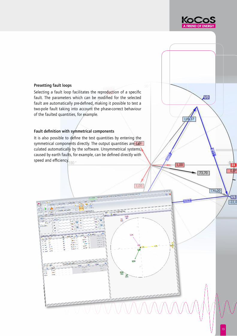
Presetting fault loops
Selecting a fault loop facilitates the reproduction of a specific fault. The parameters which can be modified for the selected fault are automatically pre-defined, making it possible to test a two-pole fault taking into account the phase-correct behaviour of the faulted quantities, for example.
fault definition with symmetrical components
It is also possible to define the test quantities by entering the symmetrical components directly. The output quantities are cal-culated automatically by the software. Unsymmetrical systems, caused by earth faults, for example, can be defined directly with speed and efficiency.
20
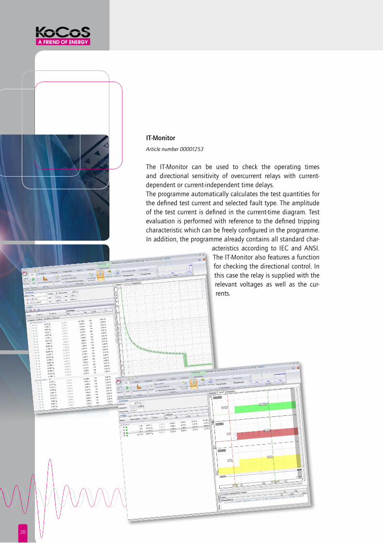
it-monitor
Article number 00001253
The IT-Monitor can be used to check the operating times and directional sensitivity of overcurrent relays with current-dependent or current-independent time delays.The programme automatically calculates the test quantities for the defined test current and selected fault type. The amplitude of the test current is defined in the current-time diagram. Test evaluation is performed with reference to the defined tripping characteristic which can be freely configured in the programme. In addition, the programme already contains all standard char-
acteristics according to IEC and ANSI. The IT-Monitor also features a function for checking the directional control. In this case the relay is supplied with the relevant voltages as well as the cur-rents.

21
imP-monitor
Article number 00001254
The IMP-Monitor can be used to check the operating times and impedance zones of distance protection devices.The programme automatically calculates the test quantities for the defined fault impedances and the selected fault type. The required fault impedance is defined in the complex impedance plane or in the distance-time diagram. In addition, the IMP-Monitor enables the ARC (Auto-Reclose) function of the protective equipment to be checked. The aim of this test is to verify the dead times of a successful or unsuccess-ful auto-reclose operation.
22
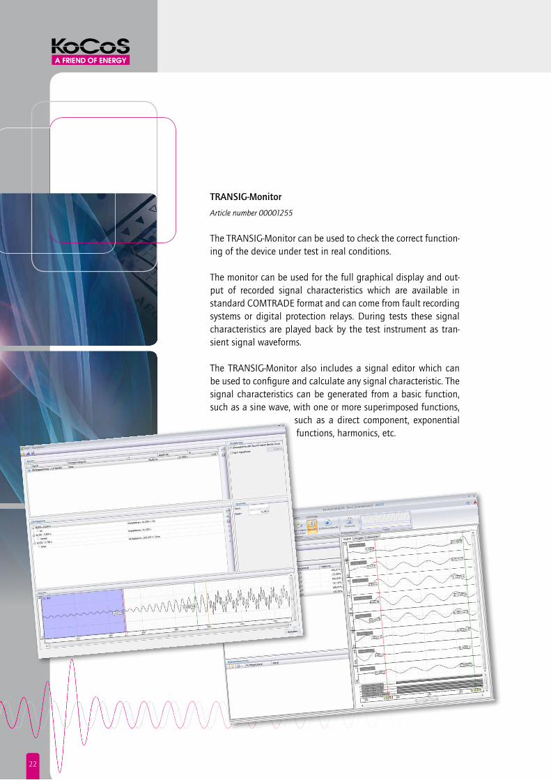
tRAnsig-monitor
Article number 00001255
The TRANSIG-Monitor can be used to check the correct function-ing of the device under test in real conditions. The monitor can be used for the full graphical display and out-put of recorded signal characteristics which are available in standard COMTRADE format and can come from fault recording systems or digital protection relays. During tests these signal characteristics are played back by the test instrument as tran-sient signal waveforms.
The TRANSIG-Monitor also includes a signal editor which can be used to configure and calculate any signal characteristic. The signal characteristics can be generated from a basic function, such as a sine wave, with one or more superimposed functions,
such as a direct component, exponential functions, harmonics, etc.
23
-90° 90°
180°
0°
too slow too fast
f < f >
U >U <
-90° 90°
180°
0°
too slow too fast
f < f >
U >U <
-90° 90°
180°
0°
too slow too fast
f < f >
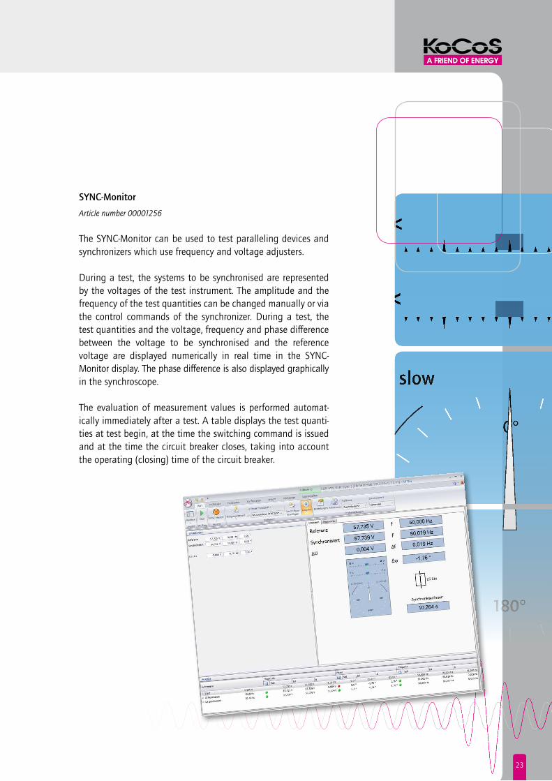
U >U <sync-monitor
Article number 00001256
The SYNC-Monitor can be used to test paralleling devices and synchronizers which use frequency and voltage adjusters.
During a test, the systems to be synchronised are represented by the voltages of the test instrument. The amplitude and the frequency of the test quantities can be changed manually or via the control commands of the synchronizer. During a test, the test quantities and the voltage, frequency and phase difference between the voltage to be synchronised and the reference voltage are displayed numerically in real time in the SYNC- Monitor display. The phase difference is also displayed graphically in the synchroscope.
The evaluation of measurement values is performed automat-ically immediately after a test. A table displays the test quanti-ties at test begin, at the time the switching command is issued and at the time the circuit breaker closes, taking into account the operating (closing) time of the circuit breaker.

24
diff-monitor
Article number 00001257
The DIFF-Monitor enables the tripping characteristic and opera-ting times of differential protection relays to be checked. Test values are calculated automatically with reference to the nominal data of the transformer and the HV/LV data. With transformers using phase-rotation vector groups, for example YD 5, the programme performs a phase adjustment between the currents of the high voltage and low voltage side which are to be compared. In addition to the vector group adjustment, an amplitude adjustment is also performed.
Test evaluation is performed with refer-ence to the stabilization characteristic of the differential protection device.

25
td-monitor
Article number 00001258
The TD-Monitor provides an easy way to test transducers. In addition to current, voltage, frequency and phase transducers, it is also possible to test active power, reactive power and apparent power transducers and devices used for measuring the power factor or reactive power factor.
The output quantity of the transducer is recorded during the test via the analog inputs of the ARTES device.In the TD-Monitor, the test quantities and the output signal of the transducer are displayed numerically in real time during tests. In addition, the absolute error, the relative error and the full scale error are calculated and displayed both numerically and graphically.

26
smartsequencer
Article number 00001259
The SmartSequencer can be used to create any kind of test pro-cedure. A test procedure is similar to a test sequence in the VD-Monitor, which can consist of a number of static and dynamic signal characteristics. However, in the VD-Monitor the individual characteristics (also termed states) have a fixed, pre-defined length and are run sequentially one after the other.Using the SmartSequencer it is possible to “run” these states in an event-controlled manner. A different progression condition (transition) can be defined for each state. This might be the reaction of the device under test in the form of a binary signal or alternatively a defined time, for example.

27
Pic-monitor
Article number 00001260
The PIC-Monitor can be used to determine the pick-up and drop-off values of protection relays.This could also be the pick-up value of the second instanta- neous tripping set (high set) of an overcurrent relay, for example. The test quantities are issued as stair-step pulsed ramps for this purpose. The amplitudes are increased until the pick-up value is reached. To ascertain the drop-off value, ARTES then automat-ically switches to a stair-step descending ramp.
The programme calculates the test quantities fully automat-ically with reference to the start and end values set for the ramps and the fault loop which has been selected. The reaction of the device under test is recorded in real time during the test and subsequently evaluated.

28
Qu-monitor
Article number 00001274
The Q-U protection function can be tested fully automatically with the QU-Monitor. The QU-Monitor supports various different response characteristics for the Q-U protection function imple-mented by the manufacturers of protection devices.
As well as verifying the tripping characteristic, it is also possible to check the pick-up and and drop-off values of the protection relay for the undervoltage threshold, the minimum current, the minimum reactive power and the angle range of the reactive power direction. Selecting a fault loop makes it possible to reproduce phaseselective fault types as well. This allows the
undervoltage threshold and the function of the logical AND-link to be checked in one test step.

29
Monitor Test function Article number
VD Test any protection function by setting the test quanti-
ties manually
Basic software
IT Check the operating times and directional sensitivity of
overcurrent relays
00001253
IMP Check the operating times and impedance zones of
distance protection devices
00001254
TRANSIG Display and output COMTRADE records and generate
any signal characteristic
00001255
SYNC Test paralleling devices and synchronizers 00001256
DIFF Check the tripping characteristic and operating times of
differential protection relays
00001257
TD Determine measuring transducer error 00001258
SmartSequencer Event-controlled output of test sequences 00001259
PIC Determine the pick-up and drop-off values of protection
relays
00001260
QU Check the Q-U protection function 00001274
Test monitor overview
Software module IEC 61850 Article number 00001261
ARTES 460|560 relay test systems can be integrated in communication according to IEC 61850-8-1. GOOSE telegrams containing trip signals, for example, are picked up and evaluated accordingly.
Professional software package Article number 00001263
Consisting of 5 software modules: IT-Monitor, IMP-Monitor, PIC-Monitor, TRANSIG-Monitor, QU-Monitor.
Premium software package Article number 00001264
Consisting of 9 software modules:IT-Monitor, IMP-Monitor, PIC-Monitor, SmartSequencer, DIFF-Monitor, SYNC-Monitor, TD-Monitor, TRANSIG-Monitor, QU-Monitor.
Software modules and packages
30
oPtions & AccessoRies
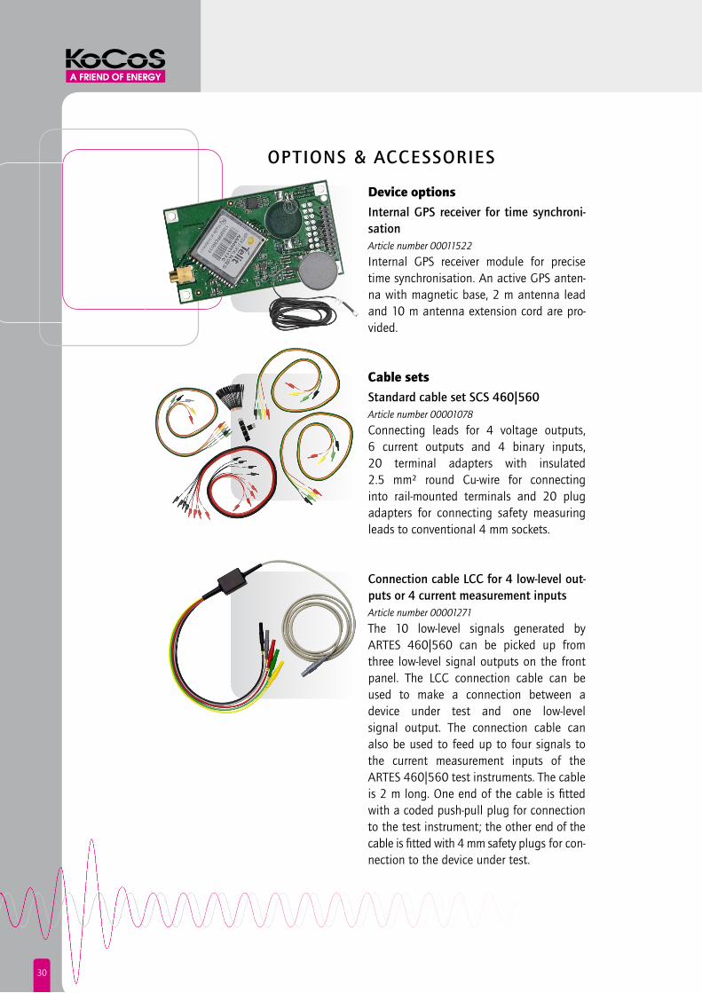
Device optionsinternal gPs receiver for time synchroni-sationArticle number 00011522
Internal GPS receiver module for precise time synchronisation. An active GPS anten-na with magnetic base, 2 m antenna lead and 10 m antenna extension cord are pro-vided.
Cable setsstandard cable set scs 460|560 Article number 00001078
Connecting leads for 4 voltage outputs, 6 current outputs and 4 binary inputs, 20 terminal adapters with insulated 2.5 mm² round Cu-wire for connecting into rail-mounted terminals and 20 plug adapters for connecting safety measuring leads to conventional 4 mm sockets.
connection cable lcc for 4 low-level out-puts or 4 current measurement inputsArticle number 00001271
The 10 low-level signals generated by ARTES 460|560 can be picked up from three low-level signal outputs on the front panel. The LCC connection cable can be used to make a connection between a device under test and one low-level signal output. The connection cable can also be used to feed up to four signals to the current measurement inputs of the ARTES 460|560 test instruments. The cable is 2 m long. One end of the cable is fitted with a coded push-pull plug for connection to the test instrument; the other end of the cable is fitted with 4 mm safety plugs for con-nection to the device under test.

31
connection cable vcc for 4 voltage mea-surement inputsArticle number 00001272
The VCC connection cable can be used to feed up to four signals to the voltage measurement inputs of ARTES 460|560 test instruments. The cable is 2 m long. One end of the cable is fitted with a coded push-pull plug for connection to the test instrument; the other end of the cable is fitted with 4 mm safety plugs for connec-tion to the device under test.
AdaptersPlug adapter PA, 25 piecesArticle number 00001170
Adapter for connecting measuring leads with 4 mm safety plugs to conventional 4 mm sockets.
terminal adapter tA, 25 piecesArticle number 00001171
Adapter for connecting measuring leads with 4 mm safety plugs to rail-mounted ter-minals. The adapter converts a 4 mm safety plug to 2.5 mm² round Cu-wire.

32
Wrap-around bags & carrying cases
wrap-around bag for ARtes 460|560Article number 00006322
Robustly made, lightly padded wrap-around bag with shoulder strap. The bag is fitted with reinforced panels for dimensional stability and features sepa-rate compartments for accessories.External dimensions: 500 x 230 x 360 mm
carrying case Rcs 160 for ARtes 460|560Article number 00006081
High-quality, robust carrying case with ABS plastic shell, anodised aluminium rim, snap locks and metal hinges. Easy manoeuvrability is provided by the re-tractable handle and smooth-rolling wheels. The case is delivered complete with a rigid foam insert to snugly fit the device inside.External dimensions: 600 x 510 x 300 mmWeight: 6.5 kg

33
tRAining couRses & seminARs
Know-how and experience
The construction and smooth operation of protection systems is a task which is becoming more and more com-plex all the time, so there is a need for specialist training courses and seminars.
Regular product training courses are held at our training centres in Korbach and Weimar, as well as on customers‘ premises. Special hands-on seminars and workshops which deal primarily with application-related themes round off our training portfolio. The training centres are well equipped with the latest measuring and test equipment for hands-on exercises.

34
Signal outputs THD < 0.05% 1)
Frequency range DC…3 kHz Transient signals DC…4 kHz Frequency resolution 0.001 Hz Frequency accuracy Error < 0.01% Phase angle 0…360° Phase resolution 0.001° Phase accuracy Error < 0.1° 1)
voltage outputs 4 x 0…300 V/75 VA 1 x 0…600 V/150 VA Resolution 13 mV THD < 0.05%1)
Accuracy Error < 0.05% 2)
current outputs ARTES 460/3 ARTES 460 ARTES 560
3 x 0...16 A /40 VA 6 x 0…16 A/40 VA 6 x 0…32 A/100 VA 3 x 0…32 A/80 VA 3 x 0…64 A/200 VA
Resolution 1 mA 1 mA 1mA Accuracy Error < 0.05% 2) Error < 0.05% 2) Error < 0.05% 2)
Max. output voltage 4 Vrms, 6 Vpk 4 Vrms, 6 Vpk 21 Vrms, 30 Vpk 2)
low-level signal outputs All low-level signal outputs can be set separately and independently of one another as regards phase, amplitude and frequency. The outputs can also be used to control external current and voltage amplifiers.
Output range 0…10 Vpk Resolution 300 µV THD < 0.01% Frequency range DC…3 kHz Transient signals DC…4 kHz Frequency resolution 0.001 Hz Frequency accuracy Error < 0.01% Max. output current 20 mA Accuracy Error < 0.02% Phase angle 0…360° Phase resolution 0.001° Phase accuracy Error < 0.05°
dc output Output range 12…260 V Protection Overload and short-circuit Output power 50 W (across the entire output range)
Analog inputs Frequency range DC…4 kHz, linear frequency response Accuracy 0.01% 2)
Protection Galvanic isolation via opto-couplers or high-speed digital isolators (icoupler®)
Voltage range 4 x 0…10 V / 600 V Current range 4 x 0…20 mA / 10 V
1) For the frequency range of 10...200 Hz 2) Of range
SPECIFICATIONS ARTES 460|560
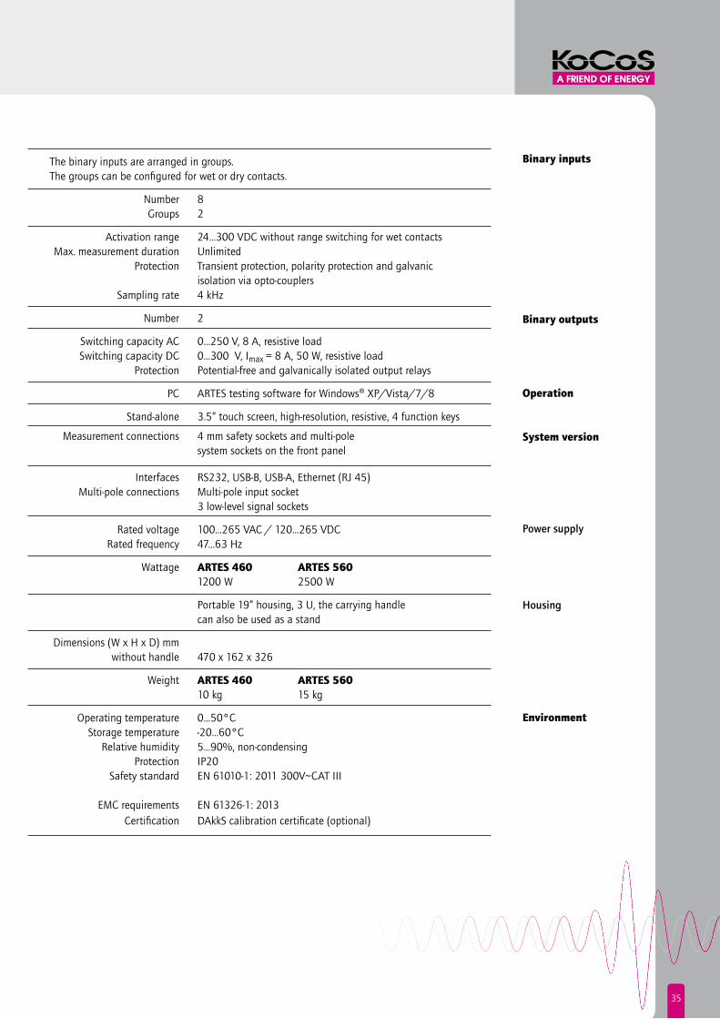
The binary inputs are arranged in groups. The groups can be configured for wet or dry contacts.
Number 8 Groups 2
Activation range 24…300 VDC without range switching for wet contacts Max. measurement duration Unlimited Protection Transient protection, polarity protection and galvanic isolation via opto-couplers Sampling rate 4 kHz
Number 2
Switching capacity AC 0…250 V, 8 A, resistive load Switching capacity DC 0…300 V, Imax = 8 A, 50 W, resistive load Protection Potential-free and galvanically isolated output relays
PC ARTES testing software for Windows® XP/Vista/7/8
Stand-alone 3.5“ touch screen, high-resolution, resistive, 4 function keys
Measurement connections 4 mm safety sockets and multi-pole system sockets on the front panel
Interfaces RS232, USB-B, USB-A, Ethernet (RJ 45) Multi-pole connections Multi-pole input socket 3 low-level signal sockets
Rated voltage 100…265 VAC / 120…265 VDC Rated frequency 47…63 Hz
Wattage ARTES 460 ARTES 560 1200 W 2500 W
Portable 19“ housing, 3 U, the carrying handle can also be used as a stand
Dimensions (W x H x D) mm without handle 470 x 162 x 326
Weight ARTES 460 ARTES 560 10 kg 15 kg
Operating temperature 0...50°C Storage temperature -20…60°C Relative humidity 5…90%, non-condensing Protection IP20 Safety standard EN 61010-1: 2011 300V~CAT III EMC requirements EN 61326-1: 2013 Certification DAkkS calibration certificate (optional)
35
The binary inputs are arranged in groups. The groups can be configured for wet or dry contacts.
Number 8 Groups 2
Activation range 24…300 VDC without range switching for wet contacts Max. measurement duration Unlimited Protection Transient protection, polarity protection and galvanic isolation via opto-couplers Sampling rate 4 kHz
Number 2
Switching capacity AC 0…250 V, 8 A, resistive load Switching capacity DC 0…300 V, Imax = 8 A, 50 W, resistive load Protection Potential-free and galvanically isolated output relays
PC ARTES testing software for Windows® XP/Vista/7/8
Stand-alone 3.5“ touch screen, high-resolution, resistive, 4 function keys
Measurement connections 4 mm safety sockets and multi-pole system sockets on the front panel
Interfaces RS232, USB-B, USB-A, Ethernet (RJ 45) Multi-pole connections Multi-pole input socket 3 low-level signal sockets
Rated voltage 100…265 VAC / 120…265 VDC Rated frequency 47…63 Hz
Wattage ARTES 460 ARTES 560 1200 W 2500 W
Portable 19“ housing, 3 U, the carrying handle can also be used as a stand
Dimensions (W x H x D) mm without handle 470 x 162 x 326
Weight ARTES 460 ARTES 560 10 kg 15 kg
Operating temperature 0...50°C Storage temperature -20…60°C Relative humidity 5…90%, non-condensing Protection IP20 Safety standard EN 61010-1: 2011 300V~CAT III EMC requirements EN 61326-1: 2013 Certification DAkkS calibration certificate (optional)
Binary inputs
Binary outputs
Operation
System version
Power supply
Housing
Environment

ARTES.
Subj
ect t
o ch
ange
with
out p
rior n
otic
e |
2015
02 I
© K
oCoS
Mes
stec
hnik
AG
KoCoS Messtechnik AGSüdring 4234497 Korbach, GermanyPhone +49 5631 [email protected]