42PQ30R.pdf
29
PLASMA TV MANUAL DE SERVICIO ATENCIÓN Antes de dar servicio al chasis, lea las PRECAUCIONES DE SEGURIDAD en este manual. CHASIS : PP91A MODELO : 42PQ30R 42PQ30R-MA North/Latin America http://aic.lgservice.com Europe/Africa http://eic.lgservice.com Asia/Oceania http://biz.lgservice.com Internal Use Only
-
Upload
dan-moroboshi -
Category
Documents
-
view
9 -
download
0
Transcript of 42PQ30R.pdf
PLASMA TVMANUAL DE SERVICIO
ATENCIÓNAntes de dar servicio al chasis, lea las PRECAUCIONES DE SEGURIDADen este manual.
CHASIS : PP91A
MODELO : 42PQ30R 42PQ30R-MA
North/Latin America http://aic.lgservice.comEurope/Africa http://eic.lgservice.comAsia/Oceania http://biz.lgservice.com
Internal Use Only
- 2 - LGE Internal Use OnlyCopyright©2009 LG Electronics. Inc. All right reserved. Only for training and service purposes
CONTENIDO
CONTENIDO ............................................................................................................................ 2
PRECAUCIONES DE SEGURIDAD .........................................................................................3
ESPECIFICACIONES ................................................................................................................4
INSTRUCCIONES DE AJUSTE ...............................................................................................8
DIAGRAMA EN BLOQUE ......................................................................................................16
VISTA EN DESPIECE .............................................................................................................17
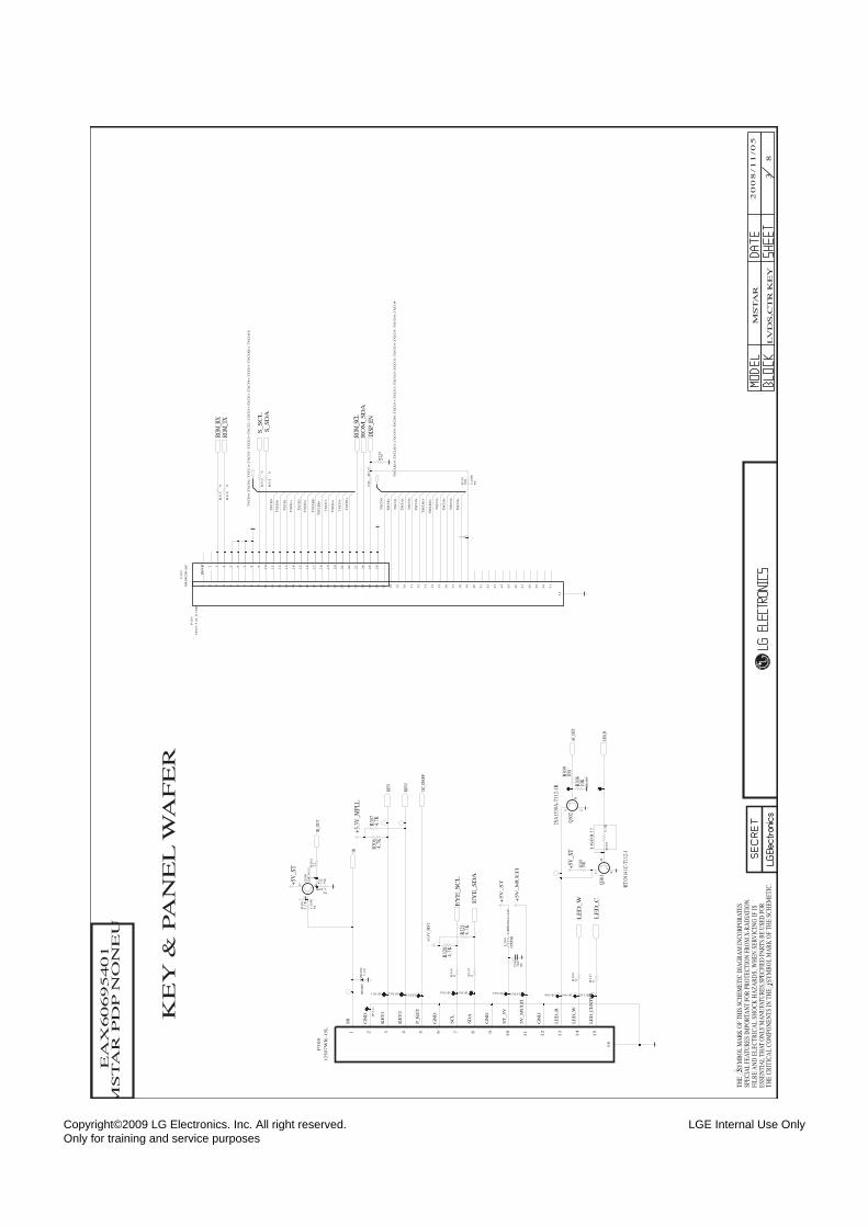
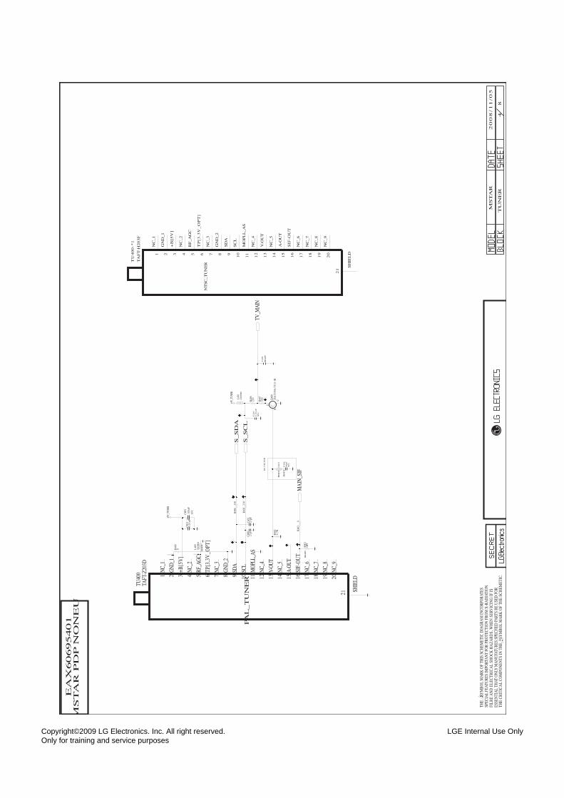
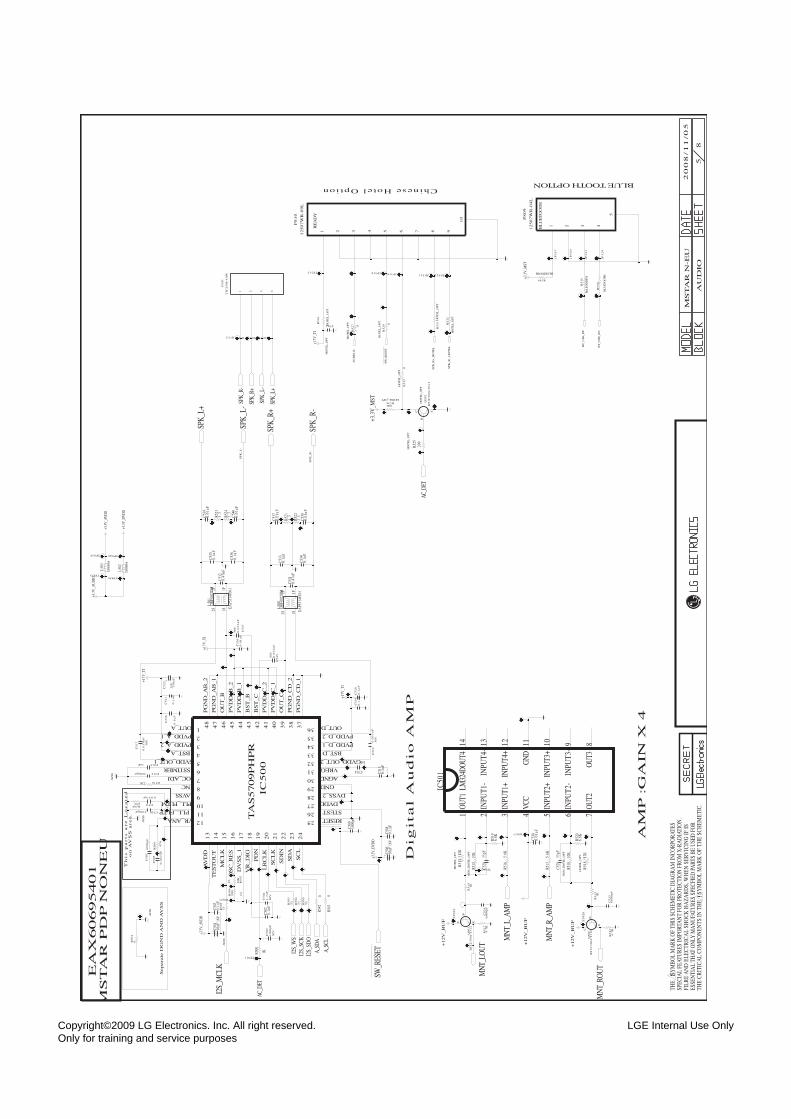
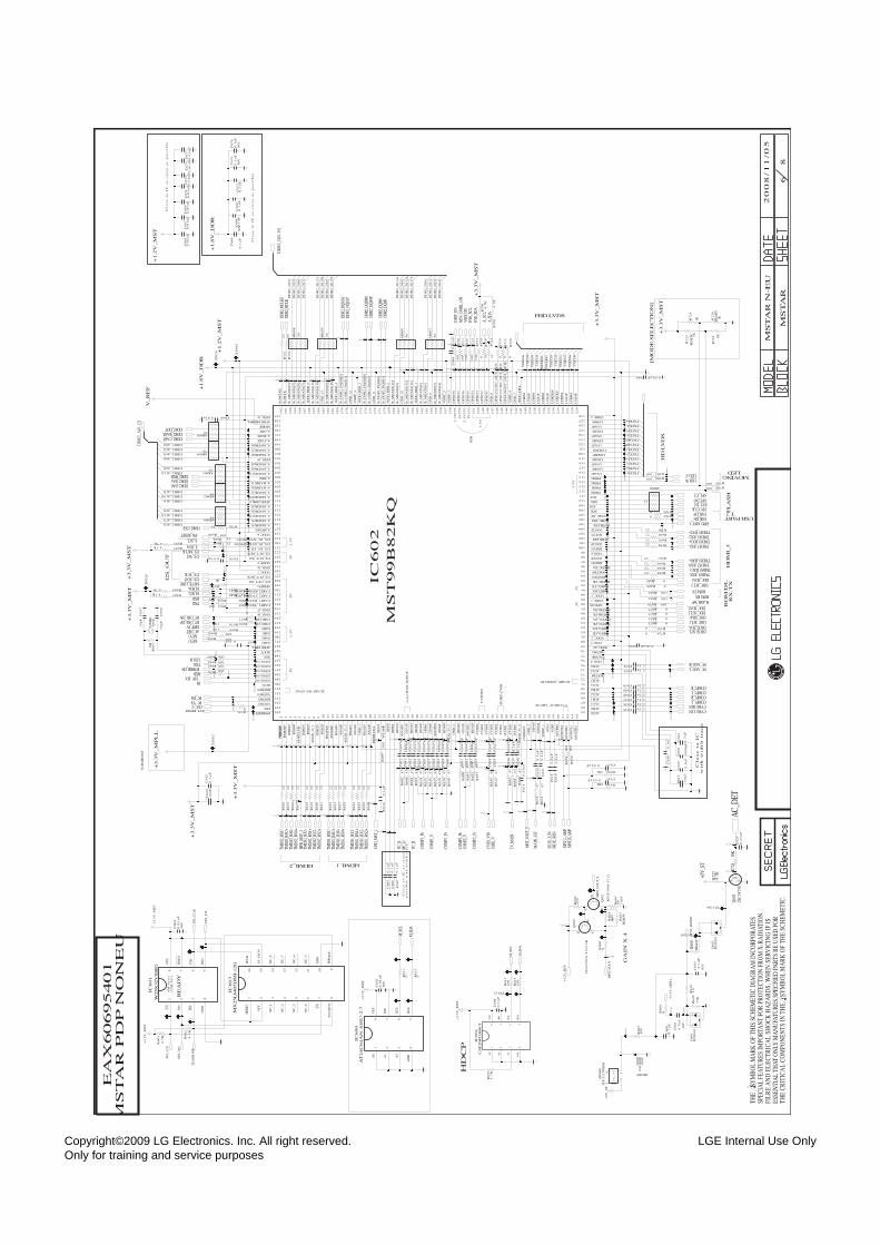
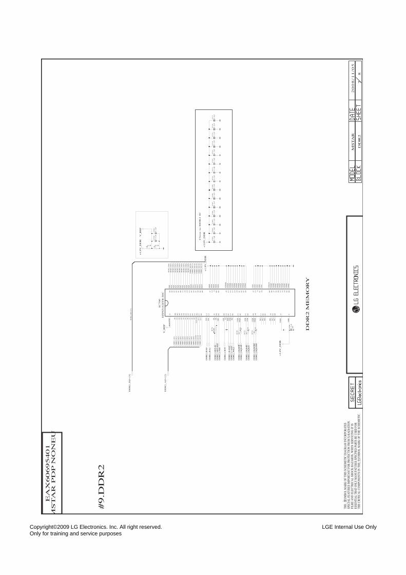
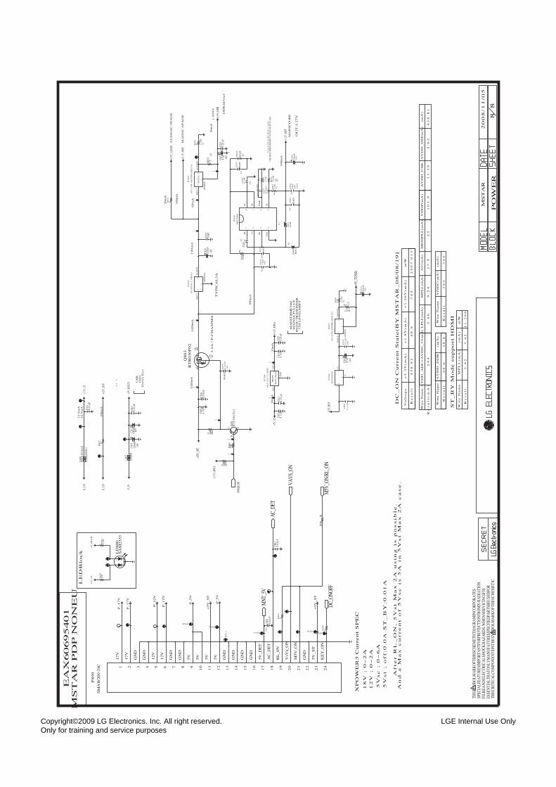
DIAGRAMA ESQUEMÁTICO......................................................................................................
TABLERO DE CIRCUITO IMPRESO ..........................................................................................
- 3 - LGE Internal Use OnlyCopyright©2009 LG Electronics. Inc. All right reserved. Only for training and service purposes
PRECAUCIONES DE SEGURIDAD
ADVERTENCIA: Antes de dar servicio a este chasis, lea "PRECAUCIONES RESPECTO A RADIACION POR RAYOS X","INSTRUCCIONES DE SEGURIDAD" y "AVISO SOBRE SEGURIDAD DE PRODUCTOS"
Muchas de las partes, electricas y mecánicas en este chasis tienen caracteristicas relacionadas con la seguridad. Estascaracteristicas frecuentemente pasan desapercibidas en las inspecciones visuales y la proteccion que proporcionan contra laRADIACION DE RAYOS-X no siempre necesariamente se obtiene al mismo grado cuando se reemplazan piezas o componentesdiseñados para voltajes o vatajes mayores, etc. Las piezas que tienen estas caracteristicas de seguridad se identifican por lamarca impresa sobre el diagrama esquematico. Antes de reemplazar alguno de esos componente, lea cuidadosamente lalista de este manual. El uso de partes de reemplazo que no tengan las mismas caracteristicas de seguridad, como se especificaen la lista de partes, puede crear Radiacion de Rayos-X.
1. Cuando el receptor está en operación, se producen voltajespotencialmente tan altos como 25,000-29,000 voltios. Operarel receptor fuera de su gabinete o con la tapa traseraremovida puede causar peligro de choque eléctrico.(1)Nadie debe intentar dar servicio si no está debidamente
familiarizado con las precauciones que son necesariascuando se trabaja con un equipo de alto voltaje.
(2)Siempre descargue el ánodo del tubo de la imagen a tierrapara evitar el riesgo de choque eléctrico antes de removerla tapa del ánodo.
(3)Descargue completamente el alto potencial del tubo deimagen antes de manipularlo. El tubo de la imagen es dealto vacío y, si se rompe, los fragmentos de vidrio salendespedidos violentamente.
2. Si se quemara algún fusible de este receptor de televisión,reemplácelo con otro especificado en la lista de partes.
3. Cuando reemplace tableros o plaquetas de circuitos,cuidadosamente enrolle sus alambres alrededor de lasterminales antes de soldar.
4. Cuando reemplace un resistencia de vataje (resistor depelícula de óxido metálico) en el Tablero o Plaqueta decircuitos, mantenga la resistencia a un mínimo de 10mm dedistancia.
5. Mantenga los alambres lejos de componentes de alto voltajeo de alta temperatura.
6. Este receptor de televisión debe conectarse a una fuente de100 a 240 V AC.
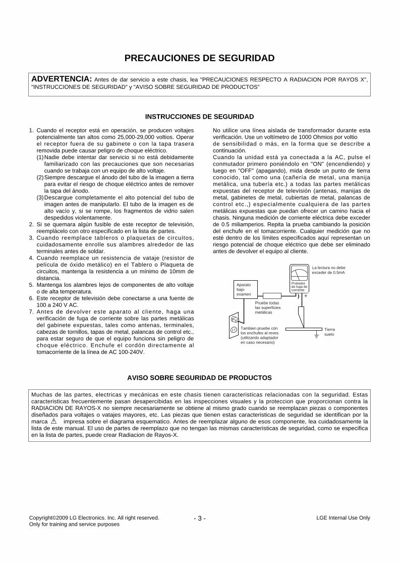
7. Antes de devolver este aparato al cl iente, haga unaverificación de fuga de corriente sobre las partes metálicasdel gabinete expuestas, tales como antenas, terminales,cabezas de tornillos, tapas de metal, palancas de control etc.,para estar seguro de que el equipo funciona sin peligro dechoque eléctrico. Enchufe el cordón directamente altomacorriente de la línea de AC 100-240V.
No utilice una línea aislada de transformador durante estaverificación. Use un voltímetro de 1000 Ohmios por voltiode sensibilidad o más, en la forma que se describe acontinuación.Cuando la unidad está ya conectada a la AC, pulse elconmutador primero poniéndolo en "ON" (encendiendo) yluego en "OFF" (apagando), mida desde un punto de tierraconocido, tal como una (cañería de metal, una manijametálica, una tubería etc.) a todas las partes metálicasexpuestas del receptor de televisión (antenas, manijas demetal, gabinetes de metal, cubiertas de metal, palancas decontrol etc.,) especialmente cualquiera de las partesmetálicas expuestas que puedan ofrecer un camino hacia elchasis. Ninguna medición de corriente eléctrica debe excederde 0.5 miliamperios. Repita la prueba cambiando la posicióndel enchufe en el tomacorriente. Cualquier medición que noesté dentro de los límites especificados aquí representan unriesgo potencial de choque eléctrico que debe ser eliminadoantes de devolver el equipo al cliente.
INSTRUCCIONES DE SEGURIDAD
AVISO SOBRE SEGURIDAD DE PRODUCTOS
DEVICEUNDERTEST
TEST ALLEXPOSED MET AL
SURFACES
2-WIRE CORD
ALSO TEST WITHPLUG REVERSED(USING AC ADAPTERPLUG AS REQUIRED)
EAR THGROUND
LEAKAGECURRENTTESTER
(READING SHOULDNO T BE ABOVE
0.5mA)
+-
Aparatobajoexamen
Probadorde fuga decorriente
La lectura no debeexceder de 0.5mA
Pruebe todaslas superficiesmetálicas
Tambien pruebe cónlos enchufes al reves(utilizando adaptadoren caso necesario)
Tierrasuelo
- 4 - LGE Internal Use OnlyCopyright©2009 LG Electronics. Inc. All right reserved. Only for training and service purposes
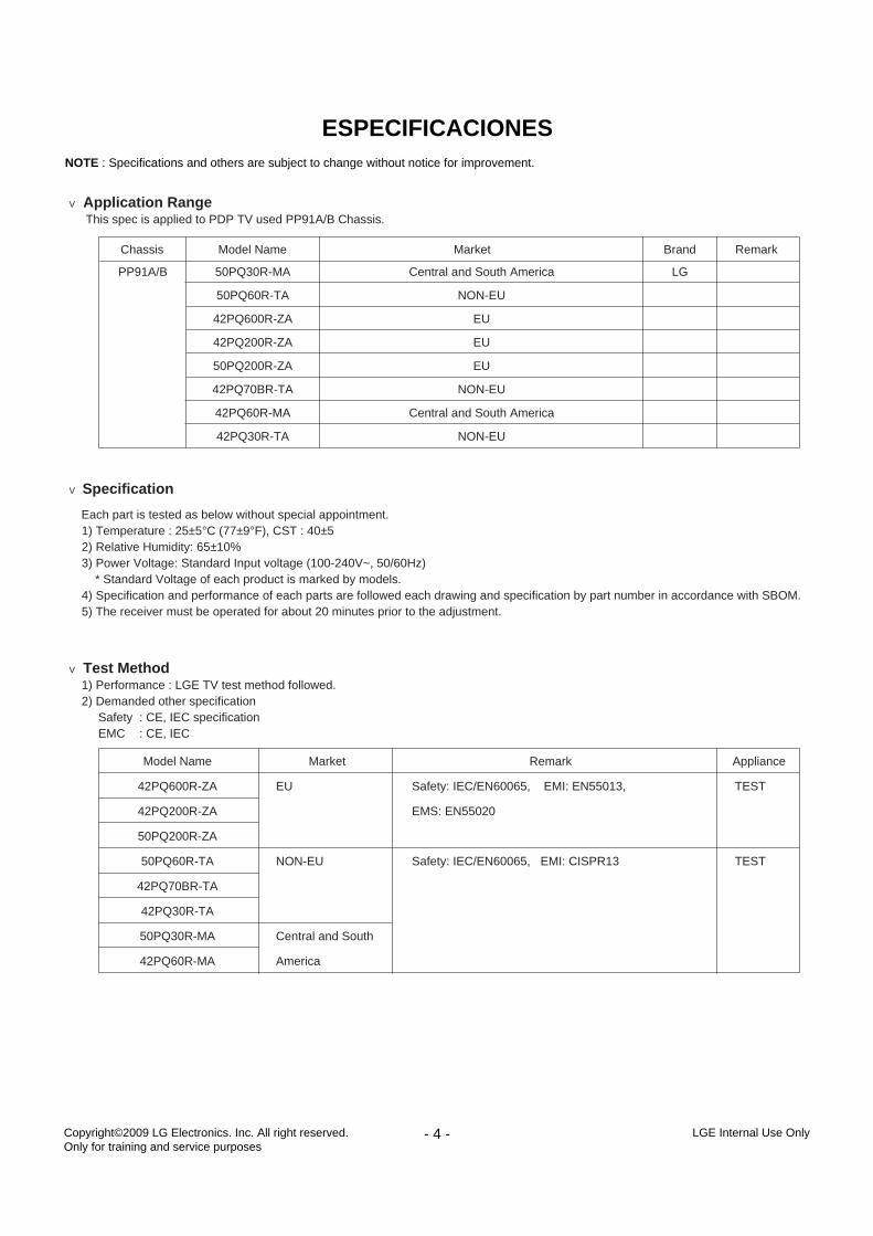
ESPECIFICACIONESNOTE : Specifications and others are subject to change without notice for improvement.
V Application RangeThis spec is applied to PDP TV used PP91A/B Chassis.
V Specification
Each part is tested as below without special appointment.1) Temperature : 25±5°C (77±9°F), CST : 40±52) Relative Humidity: 65±10%3) Power Voltage: Standard Input voltage (100-240V~, 50/60Hz)
* Standard Voltage of each product is marked by models.4) Specification and performance of each parts are followed each drawing and specification by part number in accordance with SBOM.5) The receiver must be operated for about 20 minutes prior to the adjustment.
V Test Method1) Performance : LGE TV test method followed.2) Demanded other specification
Safety : CE, IEC specificationEMC : CE, IEC
Chassis
PP91A/B 50PQ30R-MA
50PQ60R-TA
42PQ600R-ZA
42PQ200R-ZA
50PQ200R-ZA
42PQ70BR-TA
42PQ60R-MA
42PQ30R-TA
Central and South America
NON-EU
EU
EU
EU
NON-EU
Central and South America
NON-EU
LG
Model Name Market Brand Remark
Model Name
42PQ600R-ZA
42PQ200R-ZA
50PQ200R-ZA
50PQ60R-TA
42PQ70BR-TA
42PQ30R-TA
50PQ30R-MA
42PQ60R-MA
Remark
Safety: IEC/EN60065, EMI: EN55013,
EMS: EN55020
Safety: IEC/EN60065, EMI: CISPR13
Market
EU
NON-EU
Central and South
America
Appliance
TEST
TEST
- 5 - LGE Internal Use OnlyCopyright©2009 LG Electronics. Inc. All right reserved. Only for training and service purposes
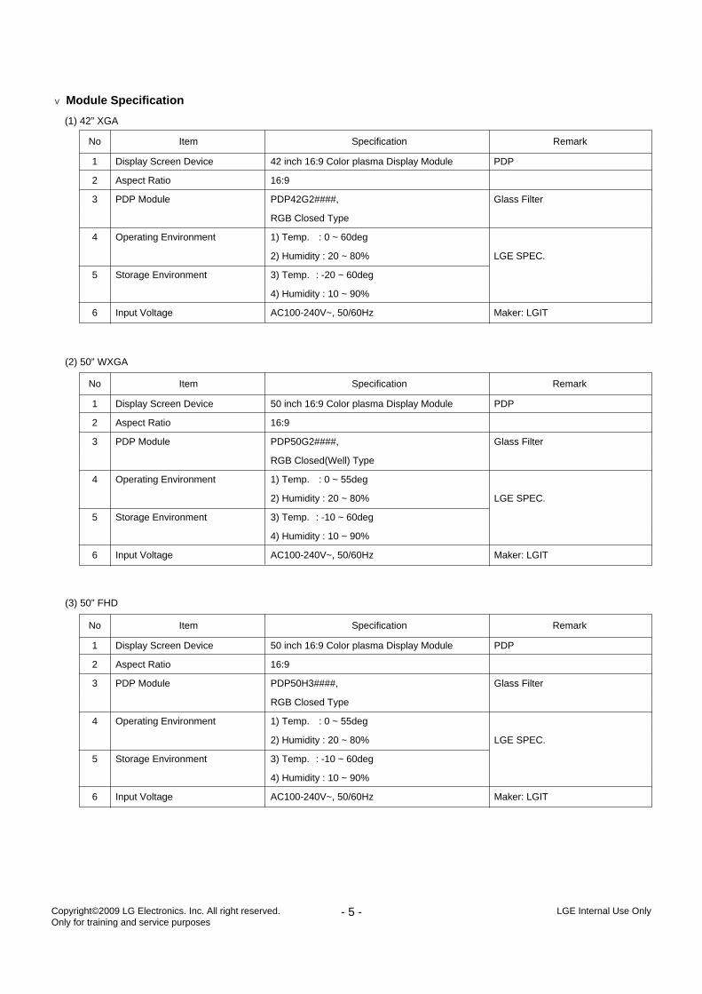
V Module Specification
(1) 42” XGA
(2) 50” WXGA
(3) 50” FHD
Display Screen Device
Aspect Ratio
PDP Module
Operating Environment
Storage Environment
Input Voltage
1
2
3
4
5
6
No Item Specification Remark
50 inch 16:9 Color plasma Display Module
16:9
PDP50G2####,
RGB Closed(Well) Type
1) Temp. : 0 ~ 55deg
2) Humidity : 20 ~ 80%
3) Temp. : -10 ~ 60deg
4) Humidity : 10 ~ 90%
AC100-240V~, 50/60Hz
PDP
Glass Filter
LGE SPEC.
Maker: LGIT
Display Screen Device
Aspect Ratio
PDP Module
Operating Environment
Storage Environment
Input Voltage
1
2
3
4
5
6
No Item Specification Remark
50 inch 16:9 Color plasma Display Module
16:9
PDP50H3####,
RGB Closed Type
1) Temp. : 0 ~ 55deg
2) Humidity : 20 ~ 80%
3) Temp. : -10 ~ 60deg
4) Humidity : 10 ~ 90%
AC100-240V~, 50/60Hz
PDP
Glass Filter
LGE SPEC.
Maker: LGIT
Display Screen Device
Aspect Ratio
PDP Module
Operating Environment
Storage Environment
Input Voltage
1
2
3
4
5
6
No Item Specification Remark
42 inch 16:9 Color plasma Display Module
16:9
PDP42G2####,
RGB Closed Type
1) Temp. : 0 ~ 60deg
2) Humidity : 20 ~ 80%
3) Temp. : -20 ~ 60deg
4) Humidity : 10 ~ 90%
AC100-240V~, 50/60Hz
PDP
Glass Filter
LGE SPEC.
Maker: LGIT
- 6 - LGE Internal Use OnlyCopyright©2009 LG Electronics. Inc. All right reserved. Only for training and service purposes
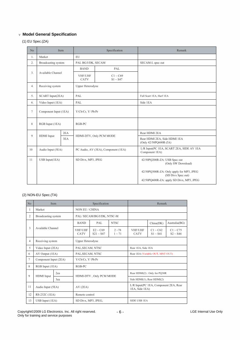
V Model General Specification
(1) EU Spec.(ZA)
(2) NON-EU Spec.(TA)
- 7 - LGE Internal Use OnlyCopyright©2009 LG Electronics. Inc. All right reserved. Only for training and service purposes
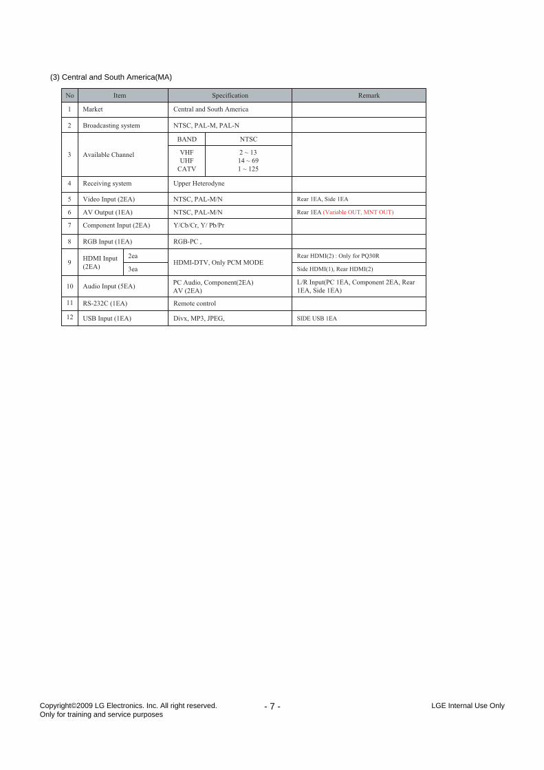
(3) Central and South America(MA)
- 8 - LGE Internal Use OnlyCopyright©2009 LG Electronics. Inc. All right reserved. Only for training and service purposes
INSTRUCCIONES DE AJUSTE
1. Application RangeThis spec sheet is applied to all of the PP91A/B chassis.
2. Specification(1) Because this is not a hot chassis, it is not necessary to use
an isolation transformer. However, the use of isolationtransformer will help protect test instrument.
(2) Adjustment must be done in the correct order.(3) The adjustment must be performed in the circumstance of
25±5°C of temperature and 65±10% of relative humidity ifthere is no specific designation.
(4) The input voltage of the receiver must keep 100~240V,50/60Hz.
(5) The receiver must be operated for about 5 minutes prior tothe adjustment when module is in the circumstance of over15°- In case of keeping module is in the circumstance of 0°C,
it should be placed in the circumstance of above 15°C for2 hours
- In case of keeping module is in the circumstance of below-20°C, it should be placed in the circumstance of above15°C for 3 hours,.
3. S/W Program Download
3-1. ProfileThis is for downloading the s/w to the flash memory of theIC603
3-2. Equipment (1) PC(2) ISP_tool program(3) Download jig
3-3. Connection Structure
3-4. Connection Condition(1) IC name and circuit number : Flash Memory and IC603(2) Use voltage : 3.3V (5 pin)(3) SCL : 15 pin(4) SDA : 12 pin(5) Tact time : about 2min and 30seconds
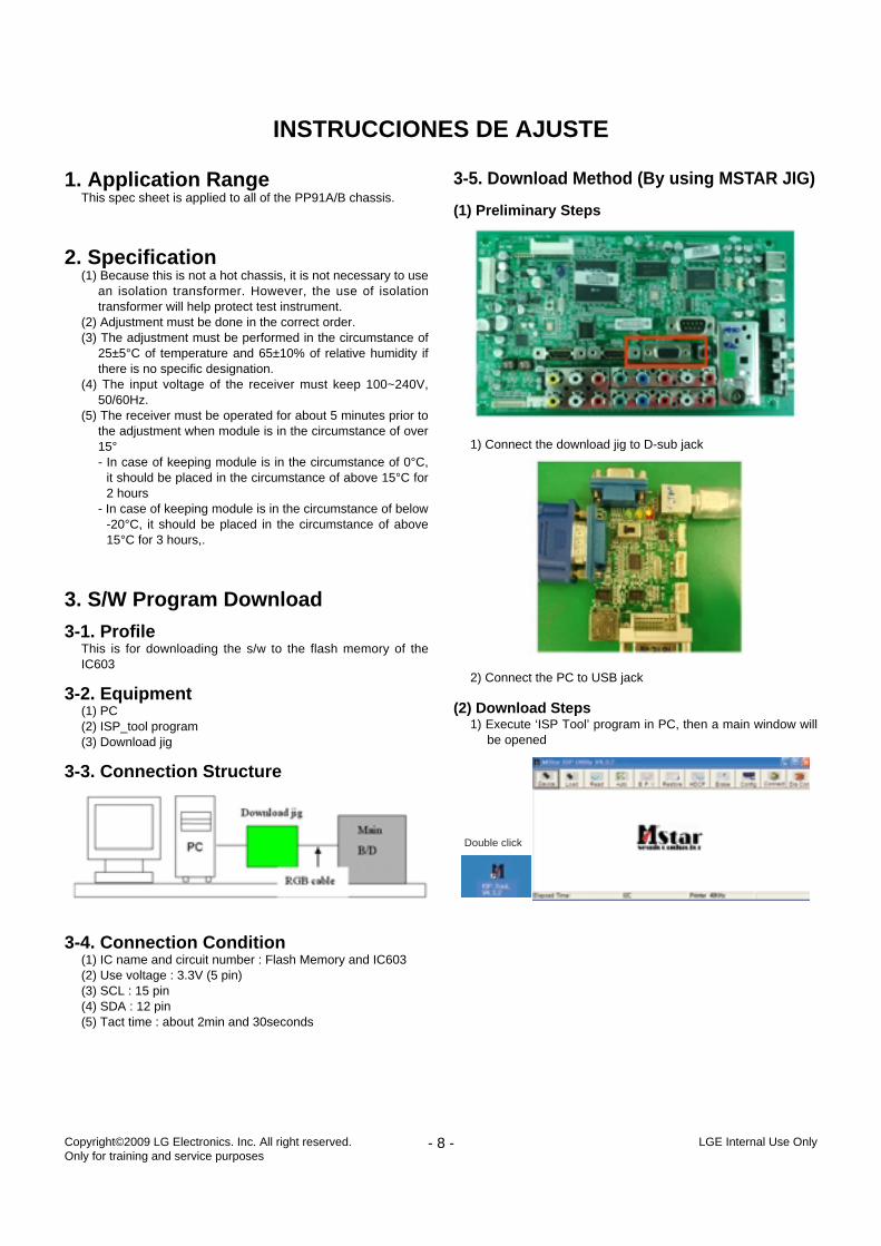
3-5. Download Method (By using MSTAR JIG)
(1) Preliminary Steps
1) Connect the download jig to D-sub jack
2) Connect the PC to USB jack
(2) Download Steps1) Execute ‘ISP Tool’ program in PC, then a main window will
be opened
Double click
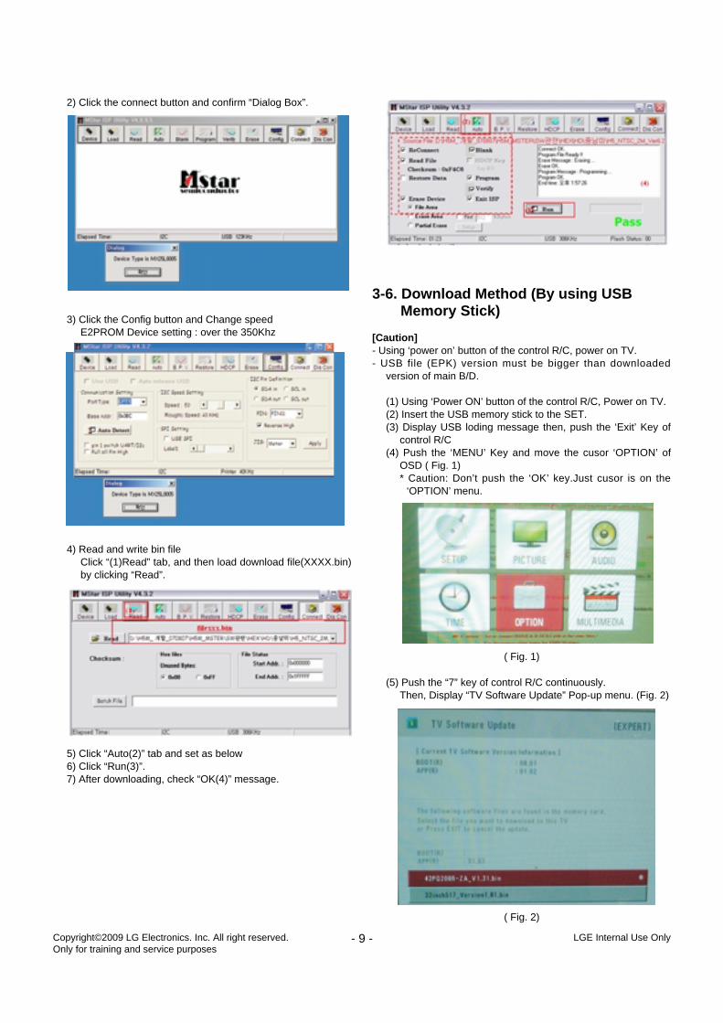
2) Click the connect button and confirm “Dialog Box”.
3) Click the Config button and Change speedE2PROM Device setting : over the 350Khz
4) Read and write bin fileClick “(1)Read” tab, and then load download file(XXXX.bin)by clicking “Read”.
5) Click “Auto(2)” tab and set as below6) Click “Run(3)”.7) After downloading, check “OK(4)” message.
3-6. Download Method (By using USB Memory Stick)
[Caution]- Using ‘power on’ button of the control R/C, power on TV.- USB file (EPK) version must be bigger than downloaded
version of main B/D.
(1) Using ‘Power ON’ button of the control R/C, Power on TV.(2) Insert the USB memory stick to the SET.(3) Display USB loding message then, push the ‘Exit’ Key of
control R/C(4) Push the ‘MENU’ Key and move the cusor ‘OPTION’ of
OSD ( Fig. 1)* Caution: Don’t push the ‘OK’ key.Just cusor is on the
‘OPTION’ menu.
(5) Push the “7” key of control R/C continuously.Then, Display “TV Software Update” Pop-up menu. (Fig. 2)
- 9 - LGE Internal Use OnlyCopyright©2009 LG Electronics. Inc. All right reserved. Only for training and service purposes
( Fig. 1)
( Fig. 2)
(6) Select SW file (XXXX.bin) you want, push the “OK” Key.(7) S/W download process is excuted automatically.
4. PCB Assembly Adjustment Method
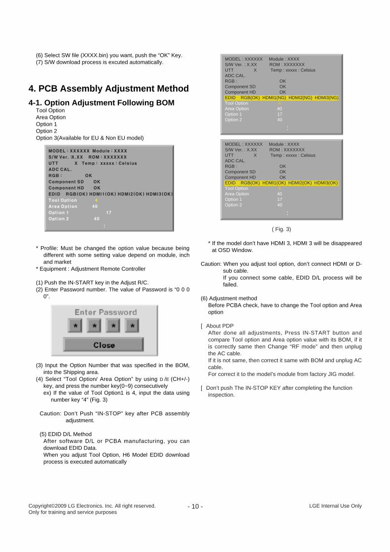
4-1. Option Adjustment Following BOM Tool OptionArea OptionOption 1Option 2Option 3(Available for EU & Non EU model)
* Profile: Must be changed the option value because beingdifferent with some setting value depend on module, inchand market
* Equipment : Adjustment Remote Controller
(1) Push the IN-START key in the Adjust R/C.(2) Enter Password number. The value of Password is “0 0 0
0”.
(3) Input the Option Number that was specified in the BOM,into the Shipping area.
(4) Select “Tool Option/ Area Option” by using D/E(CH+/-)key, and press the number key(0~9) consecutivelyex) If the value of Tool Option1 is 4, input the data using
number key “4” (Fig. 3)
Caution: Don’t Push “IN-STOP” key after PCB assemblyadjustment.
(5) EDID D/L MethodAfter software D/L or PCBA manufacturing, you candownload EDID Data.When you adjust Tool Option, H6 Model EDID downloadprocess is executed automatically
* If the model don’t have HDMI 3, HDMI 3 will be disappearedat OSD Window.
Caution: When you adjust tool option, don’t connect HDMI or D-sub cable. If you connect some cable, EDID D/L process will befailed.
(6) Adjustment method Before PCBA check, have to change the Tool option and Areaoption
[ About PDPAfter done all adjustments, Press IN-START button andcompare Tool option and Area option value with its BOM, if itis correctly same then Change “RF mode” and then unplugthe AC cable.If it is not same, then correct it same with BOM and unplug ACcable. For correct it to the model’s module from factory JIG model.
[ Don’t push The IN-STOP KEY after completing the functioninspection.
- 10 - LGE Internal Use OnlyCopyright©2009 LG Electronics. Inc. All right reserved. Only for training and service purposes
..
..
MODEL : XXXXXX Module : XXXXS/W Ver. : X.XX ROM : XXXXXXXUTT X Temp : xxxxx : CelsiusADC CAL.RGB : OK Component SD OK Component HD OK EDID RGB(OK) HDMI1(NG) HDMI2(NG) HDMI3(NG)Tool Option 4Area Option 40Option 1 17Option 2 40
..
MODEL : XXXXXX Module : XXXXS/W Ver. : X.XX ROM : XXXXXXXUTT X Temp : xxxxx : CelsiusADC CAL.RGB : OK Component SD OK Component HD OK EDID RGB(OK) HDMI1(OK) HDMI2(OK) HDMI3(OK)Tool Option 4Area Option 40Option 1 17Option 2 40
( Fig. 3)
5. EDID(The Extended DisplayIdentification Data)
Originally H6(PP91A/B) Model EDID download process isexecuted when you adjust Tool Option.
[ Caution- Use the proper signal cable for EDID Download- Never connect HDMI & D-SUB Cable at the same time.- Use the proper cables below for EDID Writing
5-1. Profile: To be possible for plug and play
5-2. Equipment(1) Adjusting PC with S/W for writing EDID Data.(S/W: EDID
TESTER Ver.2.5)(2) A Jig for EDID Download(3) Cable : Serial(9Pin or USB) to D-sub 15Pin cable, D-sub
15Pin cable, DVI to HDMI cable.
5-3. Connection Structure
Caution: Never connect HDMI & D-SUB Cable at the same time.
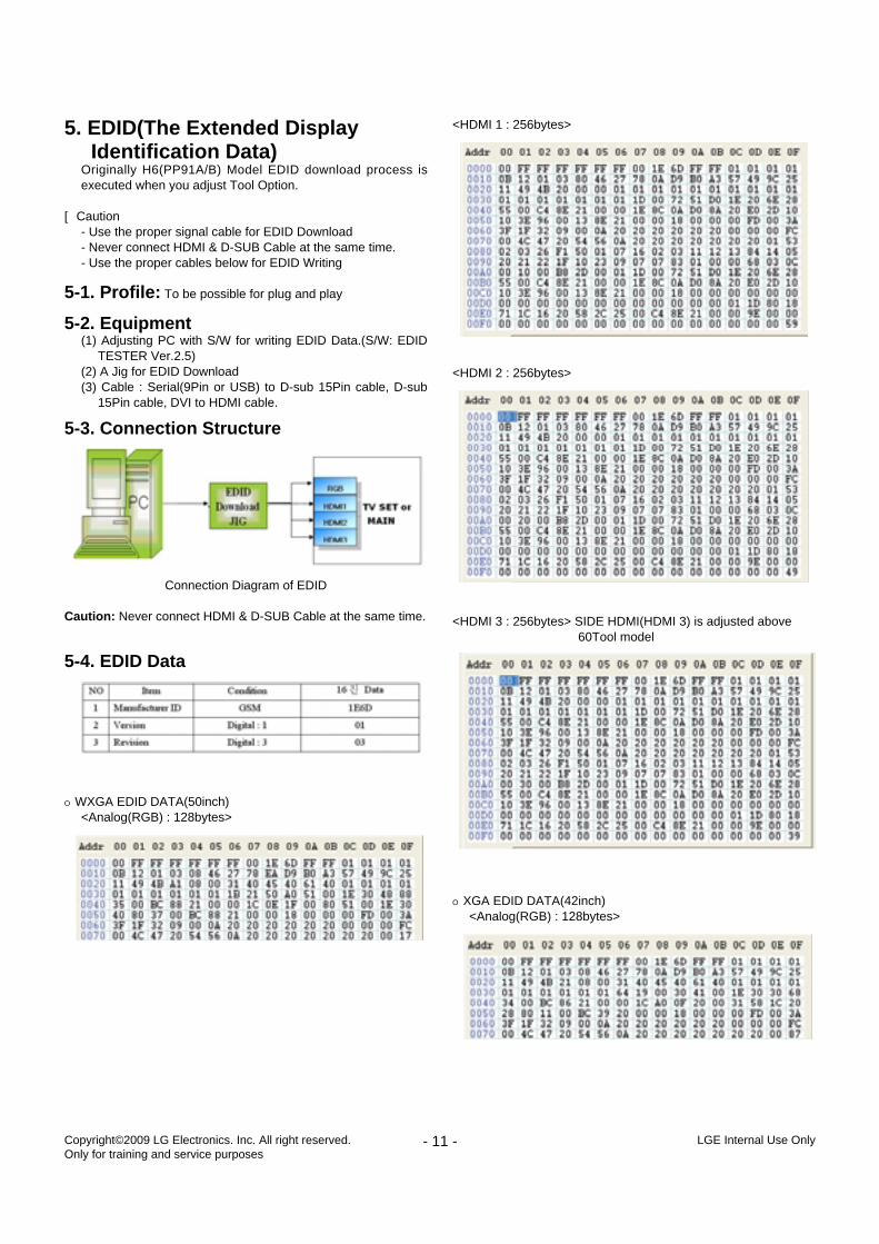
5-4. EDID Data
O WXGA EDID DATA(50inch)<Analog(RGB) : 128bytes>
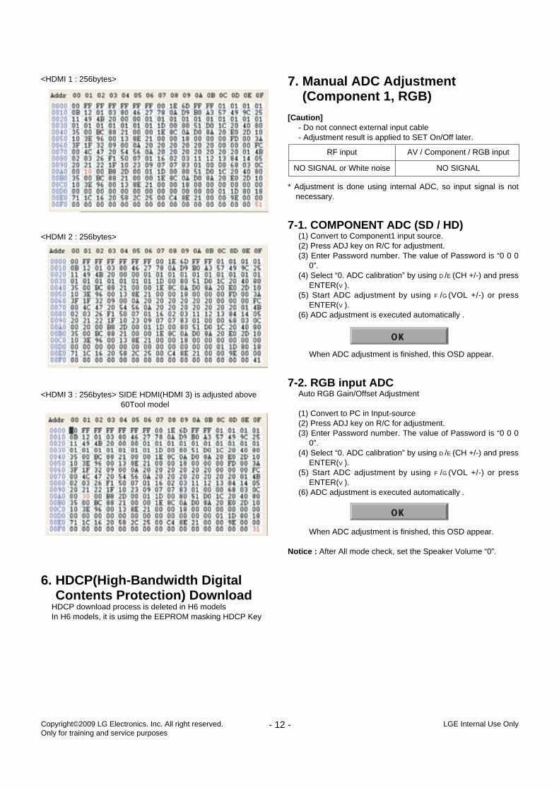
<HDMI 1 : 256bytes>
<HDMI 2 : 256bytes>
<HDMI 3 : 256bytes> SIDE HDMI(HDMI 3) is adjusted above 60Tool model
O XGA EDID DATA(42inch)<Analog(RGB) : 128bytes>
- 11 - LGE Internal Use OnlyCopyright©2009 LG Electronics. Inc. All right reserved. Only for training and service purposes
Connection Diagram of EDID
<HDMI 1 : 256bytes>
<HDMI 2 : 256bytes>
<HDMI 3 : 256bytes> SIDE HDMI(HDMI 3) is adjusted above 60Tool model
6. HDCP(High-Bandwidth Digital Contents Protection) Download
HDCP download process is deleted in H6 modelsIn H6 models, it is usimg the EEPROM masking HDCP Key
7. Manual ADC Adjustment (Component 1, RGB)
[Caution]- Do not connect external input cable- Adjustment result is applied to SET On/Off later.
* Adjustment is done using internal ADC, so input signal is notnecessary.
7-1. COMPONENT ADC (SD / HD) (1) Convert to Component1 input source.(2) Press ADJ key on R/C for adjustment.(3) Enter Password number. The value of Password is “0 0 0
0”.(4) Select “0. ADC calibration” by using D/E(CH +/-) and press
ENTER(V).(5) Start ADC adjustment by using F/G(VOL +/-) or press
ENTER(V).(6) ADC adjustment is executed automatically .
When ADC adjustment is finished, this OSD appear.
7-2. RGB input ADCAuto RGB Gain/Offset Adjustment
(1) Convert to PC in Input-source(2) Press ADJ key on R/C for adjustment.(3) Enter Password number. The value of Password is “0 0 0
0”.(4) Select “0. ADC calibration” by using D/E(CH +/-) and press
ENTER(V).(5) Start ADC adjustment by using F/G(VOL +/-) or press
ENTER(V).(6) ADC adjustment is executed automatically .
When ADC adjustment is finished, this OSD appear.
Notice : After All mode check, set the Speaker Volume “0”.
- 12 - LGE Internal Use OnlyCopyright©2009 LG Electronics. Inc. All right reserved. Only for training and service purposes
RF input
NO SIGNAL or White noise
AV / Component / RGB input
NO SIGNAL
Notice : From this sentence, All working is mass production.
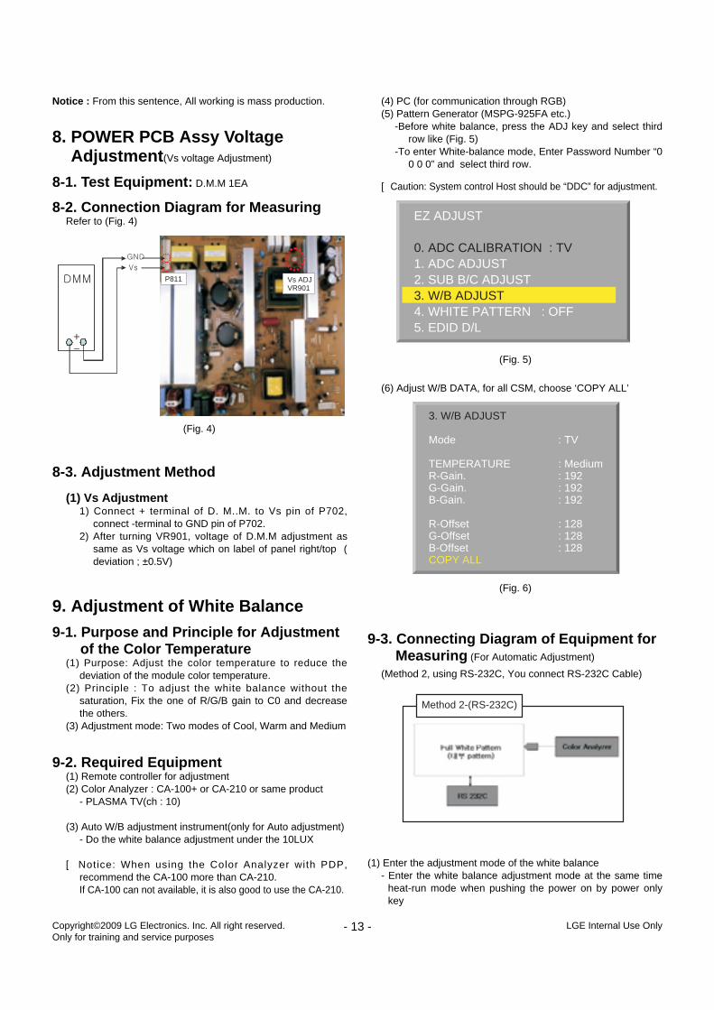
8. POWER PCB Assy VoltageAdjustment(Vs voltage Adjustment)
8-1. Test Equipment: D.M.M 1EA
8-2. Connection Diagram for MeasuringRefer to (Fig. 4)
8-3. Adjustment Method
(1) Vs Adjustment1) Connect + terminal of D. M..M. to Vs pin of P702,
connect -terminal to GND pin of P702.2) After turning VR901, voltage of D.M.M adjustment as
same as Vs voltage which on label of panel right/top (deviation ; ±0.5V)
9. Adjustment of White Balance
9-1. Purpose and Principle for Adjustment of the Color Temperature
(1) Purpose: Adjust the color temperature to reduce thedeviation of the module color temperature.
(2) Principle : To adjust the white balance without thesaturation, Fix the one of R/G/B gain to C0 and decreasethe others.
(3) Adjustment mode: Two modes of Cool, Warm and Medium
9-2. Required Equipment(1) Remote controller for adjustment (2) Color Analyzer : CA-100+ or CA-210 or same product
- PLASMA TV(ch : 10)
(3) Auto W/B adjustment instrument(only for Auto adjustment)- Do the white balance adjustment under the 10LUX
[ Notice: When using the Color Analyzer with PDP,recommend the CA-100 more than CA-210.If CA-100 can not available, it is also good to use the CA-210.
(4) PC (for communication through RGB) (5) Pattern Generator (MSPG-925FA etc.)
-Before white balance, press the ADJ key and select thirdrow like (Fig. 5)
-To enter White-balance mode, Enter Password Number “00 0 0” and select third row.
[ Caution: System control Host should be “DDC” for adjustment.
(6) Adjust W/B DATA, for all CSM, choose ‘COPY ALL’
9-3. Connecting Diagram of Equipment for Measuring (For Automatic Adjustment)
(Method 2, using RS-232C, You connect RS-232C Cable)
(1) Enter the adjustment mode of the white balance- Enter the white balance adjustment mode at the same time
heat-run mode when pushing the power on by power onlykey
- 13 - LGE Internal Use OnlyCopyright©2009 LG Electronics. Inc. All right reserved. Only for training and service purposes
P811 Vs ADJVR901
(Fig. 4)
EZ ADJUST
0. ADC CALIBRATION : TV1. ADC ADJUST2. SUB B/C ADJUST3. W/B ADJUST4. WHITE PATTERN : OFF5. EDID D/L
(Fig. 5)
3. W/B ADJUST
Mode : TV
TEMPERATURE : MediumR-Gain. : 192G-Gain. : 192B-Gain. : 192
R-Offset : 128G-Offset : 128B-Offset : 128COPY ALL
(Fig. 6)
Method 2-(RS-232C)
- Maintain the white balance adjustment mode with samecondition of Heat-run
- Maintain after AC off/on in status of Heat-run pattern display
(2) Release the white balance adjustment mode- Release the adjust mode after AC off/on or std-by off/on in
status of finishing the Hear-run mode- Release the Adjust mode when receiving the aging off
command(F3 00 00) from adjustment equipment)
(3) Enter the adjust mode of white balance- Enter the white balance adjustment mode with aging
command(F3, 00, FF)
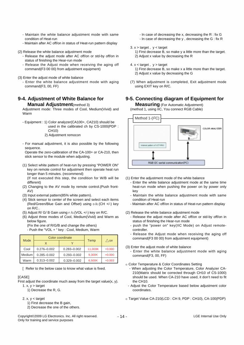
9-4. Adjustment of White Balance for Manual Adjustment(method 3)
Adjustment mode: Three modes of Cool, Medium(Vivid) andWarm
- Equipment : 1) Color analyzer(CA100+, CA210) should beused in the calibrated ch by CS-1000(PDP :CH10)
2) Adjustment remocon
- For manual adjustment, it is also possible by the followingsequence.Operate the zero-calibration of the CA-100+ or CA-210, thenstick sensor to the module when adjusting.
(1) Select white pattern of heat-run by pressing “POWER ON”key on remote control for adjustment then operate heat runlonger than 5 minutes. (recommend) (If not executed this step, the condition for W/B will bedifferent)
(2) Changing to the AV mode by remote control.(Push front-AV)
(3) Input external pattern(85% white pattern).(4) Stick sensor to center of the screen and select each items
(Red/Green/Blue Gain and Offset) using D/E(CH +/-) keyon R/C..
(5) Adjust R/ G/ B Gain using F/G(VOL +/-) key on R/C.(6) Adjust three modes of Cool, Medium(Vivid) and Warm as
below figure.(Fix the one of R/G/B and change the others)- Push the “VOL + “ key : Cool, Medium, Warm
[ Refer to the below case to know what value is fixed.
[CASE]First adjust the coordinate much away from the target value(x, y).
1. x, y > target1) Decrease the R, G.
2. x, y < target1) First decrease the B gain, 2) Decrease the one of the others.
- In case of decreasing the x, decreasing the R : fix G- In case of decreasing the y , decreasing the G : fix R
3. x > target , y < target1) First decrease B, so make y a little more than the target.2) Adjust x value by decreasing the R
4. x < target , y > target1) First decrease B, so make x a little more than the target.2) Adjust x value by decreasing the G
(7) When adjustment is completed, Exit adjustment modeusing EXIT key on R/C.
9-5. Connecting diagram of Equipment for Measuring (For Automatic Adjustment)
(method 1, using IIC, You connect RGB Cable)
(1) Enter the adjustment mode of the white balance- Enter the white balance adjustment mode at the same time
heat-run mode when pushing the power on by power onlykey
- Maintain the white balance adjustment mode with samecondition of Heat-run
- Maintain after AC off/on in status of Heat-run pattern display
(2) Release the white balance adjustment mode- Release the adjust mode after AC off/on or std-by off/on in
status of finishing the Hear-run mode- push the “power on” key(IIC Mode) on Adjust remote-
controller.- Release the Adjust mode when receiving the aging off
command(F3 00 00) from adjustment equipment)
(3) Enter the adjust mode of white balance- Enter the white balance adjustment mode with aging
command(F3, 00, FF)
O Color Temperature & Color Coordinates Setting- When adjusting the Color Temperature, Color Analyzer CA-
210(Matrix should be corrected through CH10 of CS-1000)should be used. When CA-210 have used, it don’t need to fitthe CH10.
- Adjust the Color Temperature based below adjustment colorcoordinates.
O Target Value CA-210(LCD : CH 9, PDP : CH10), CA-100(PDP)
- 14 - LGE Internal Use OnlyCopyright©2009 LG Electronics. Inc. All right reserved. Only for training and service purposes
+0.0036,500KWarm
+0.0009,300KMedium
+0.00011,000KCool 0.276–0.002
0.285–0.002 0.293–0.002
0.329–0.0020.313–0.002
0.283–0.002
YXuvTemp
Color coordinateMode
Method 1-(I2C)
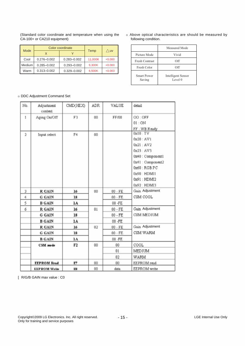
(Standard color coordinate and temperature when using theCA-100+ or CA210 equipment)
O Above optical characteristics are should be measured byfollowing condition.
- 15 - LGE Internal Use OnlyCopyright©2009 LG Electronics. Inc. All right reserved. Only for training and service purposes
+0.0036,500KWarm
+0.0009,300KMedium
+0.00011,000KCool 0.276–0.002
0.285–0.002 0.293–0.002
0.329–0.0020.313–0.002
0.283–0.002
YXuvTemp
Color coordinateMode
O DDC Adjustment Command Set
[ R/G/B GAIN max value : C0
Adjustment
Adjustment
Adjustment
- 16 - LGE Internal Use OnlyCopyright©2009 LG Electronics. Inc. All right reserved. Only for training and service purposes
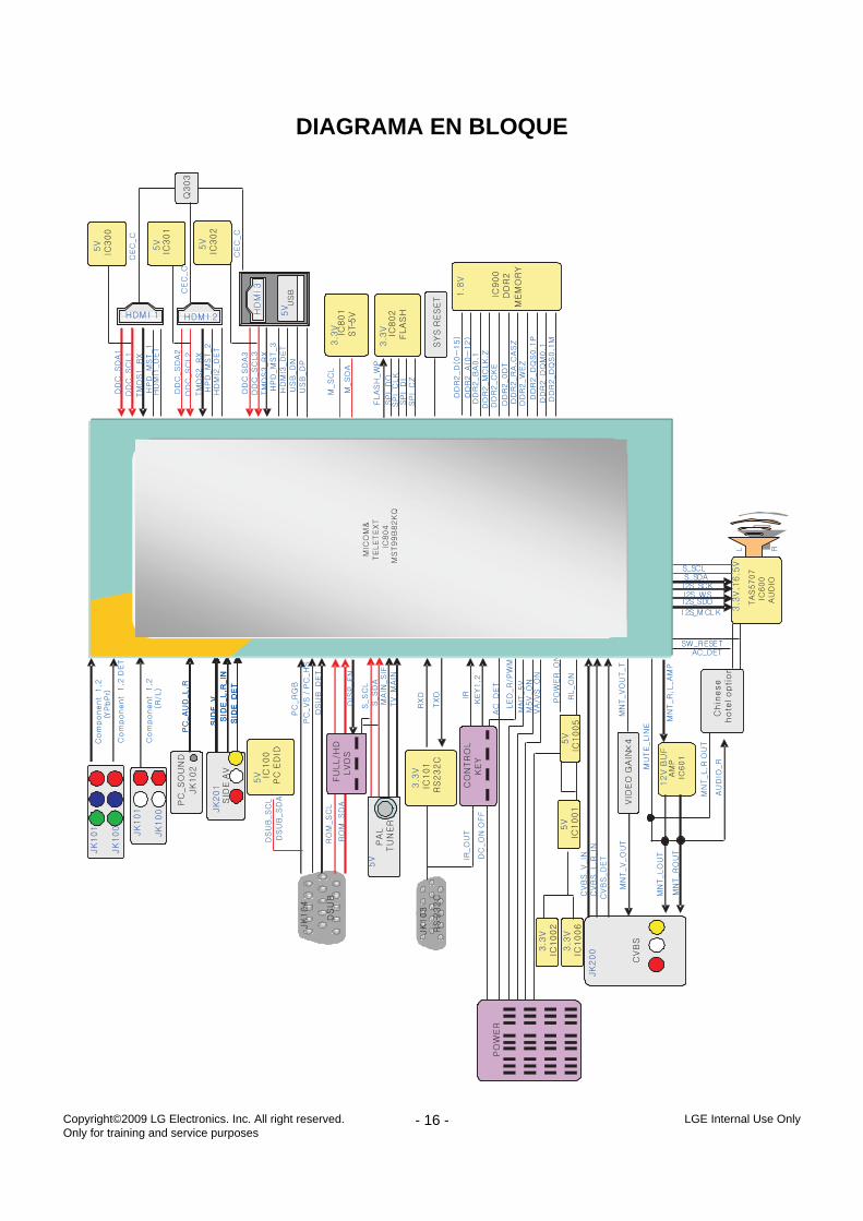
DIAGRAMA EN BLOQUE
A10
900
901
400
520
590
240
250
300
305
301
303
560
561
310
330
302
200
120
580 26
0
270
603
602
601
501
570
A2
LV1
201
203
205
204
206
202
- 17 - LGE Internal Use Only
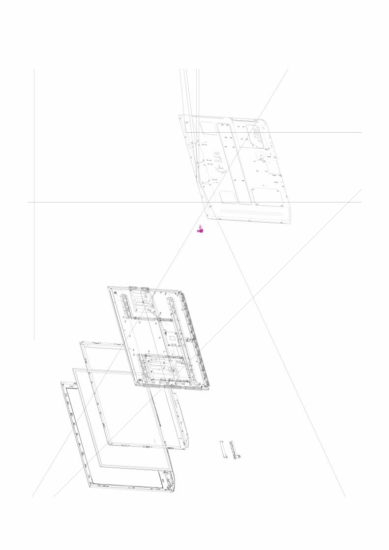
VISTA EN DESPIECE
Many electrical and mechanical parts in this chassis have special safety-related characteristics. Theseparts are identified by in the Schematic Diagram and EXPLODED VIEW. It is essential that these special safety parts should be replaced with the same components asrecommended in this manual to prevent X-RADIATION, Shock, Fire, or other Hazards. Do not modify the original design without permission of manufacturer.
IMPORTANT SAFETY NOTICE
LGE Internal Use OnlyCopyright©2009 LG Electronics. Inc. All right reserved. Only for training and service purposes
LGE Internal Use OnlyCopyright©2009 LG Electronics. Inc. All right reserved. Only for training and service purposes
LGE Internal Use OnlyCopyright©2009 LG Electronics. Inc. All right reserved. Only for training and service purposes
LGE Internal Use OnlyCopyright©2009 LG Electronics. Inc. All right reserved. Only for training and service purposes
LGE Internal Use OnlyCopyright©2009 LG Electronics. Inc. All right reserved. Only for training and service purposes
LGE Internal Use OnlyCopyright©2009 LG Electronics. Inc. All right reserved. Only for training and service purposes
LGE Internal Use OnlyCopyright©2009 LG Electronics. Inc. All right reserved. Only for training and service purposes
LGE Internal Use OnlyCopyright©2009 LG Electronics. Inc. All right reserved. Only for training and service purposes
LGE Internal Use OnlyCopyright©2009 LG Electronics. Inc. All right reserved. Only for training and service purposes
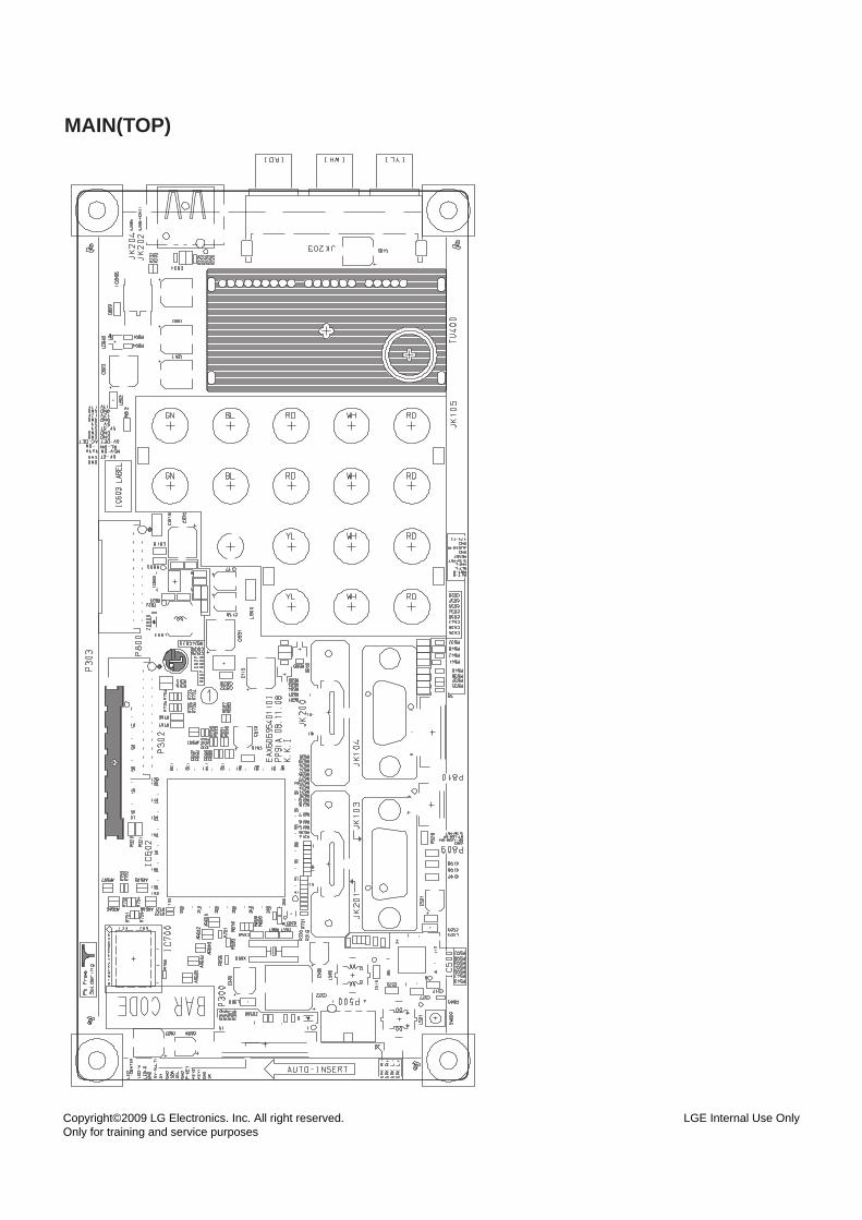
MAIN(TOP)
LGE Internal Use OnlyCopyright©2009 LG Electronics. Inc. All right reserved. Only for training and service purposes
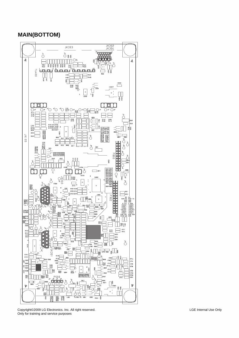
MAIN(BOTTOM)
LGE Internal Use OnlyCopyright©2009 LG Electronics. Inc. All right reserved. Only for training and service purposes
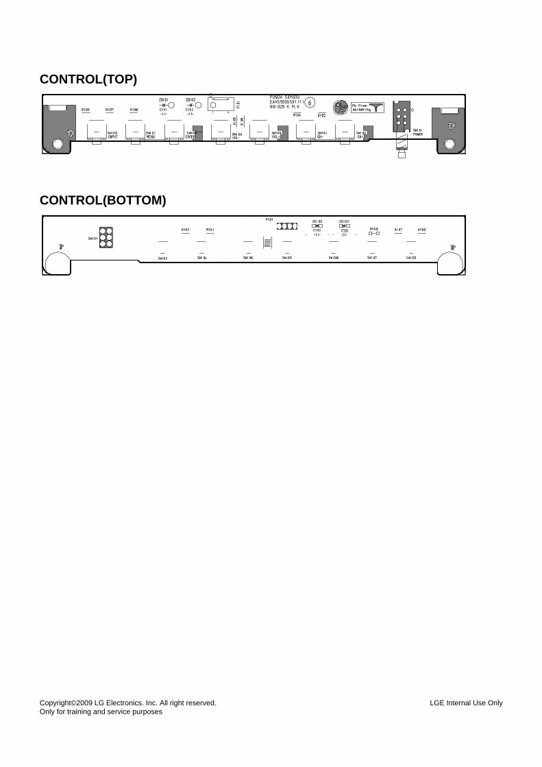
CONTROL(TOP)
CONTROL(BOTTOM)
Jan., 2009Printed in KoreaP/NO : MFL58373006