


Línguas
Páginas
Legal


INSTITUTO SUPERIOR DE ENGENHARIA DE LISBOA
Área Departamental de Engenharia Electrónica e
Telecomunicações e de Computadores
Fly by Data Link: Feasibility of a Relative Navigation
Solution for Aviation Relying on a Future L-Band Data
Link
JORGE AFONSO PEREIRA
Trabalho Final de Mestrado para Obtenção do Grau de Mestre em Engenharia de Electrónica e Telecomunicações
Orientador: Doutor Pedro Manuel de Almeida Carvalho Vieira
Juri:
Presidente: Doutor Mário Pereira Véstias
Vogal-Arguente: Doutor Paulo Alexandre Carapinha Marques
Vogal-Orientador: Doutor Pedro Manuel de Almeida Carvalho Vieira
[Versão 2.0]
04 DEZEMBRO 2015

2
(Page intentionally left blank)

3
ACKNOWLEDGMENTS
I shall express my appreciation to the Portuguese Air Force, where I have fulfilled 22 years
of my professional career, for the opportunity offered to acquire the aeronautical culture
fundamental for the development of the present work.
The same recognition applies to the European Organization for the Safety of Air
Navigation (EUROCONTROL) in Brussels – Belgium, where I work since 2002 in the
technical domain related with the topics covered in the present thesis.
The patience, support and love of my wife Maria and my daughter Francisca were
fundamental to allow me to successfully complete this work.
A final word goes to the support and coaching offered by Doctor Pedro Vieira for accepting
to steer me in such unusual theme and for giving me critical baseline capabilities in relevant
mobile communications domains.

4
(Page intentionally left blank)

5
ABSTRACT
The main purpose of this work is to study an alternative solution for aeronautical aircraft
navigation contributing to the rationalization of the existing European ground navigation
infrastructure.
The emerging Performance Based Navigation (PBN) concept, described in the document
9613 of the International Civil Aviation Organization (ICAO), calls for increased reliance
on Global Navigation Satellite Systems (GNSS) (and its augmentation/differential
correction systems1) but retaining ground beacons such as the Distance Measuring
Equipments (DME) to cope with Global Positioning System (GPS) and GALILEO outages
(e.g. jamming/solar storms).
The present work will focus on demonstrating the feasibility of an alternative technology to
allow the decommissioning of such DME beacons based on the re-use of future L-Band Air
Ground Data Link (LDACS) communication solutions being subject of research studies.
Such data links may support the required levels of positioning, navigation and timing
required to complement GNSS when the aircraft fly in an area navigation environment.
This work will describe the LDACS data link technologies2 and will explain how such
communications enablers would be able to support a “relative navigation” function similar
to the one available in military data link technologies using a geodetic grid.
The feasibility of the proposed solution will be demonstrated on the basis of lessons learnt
from military relative navigation and simulations which will evidence the technical
performance/error parameters of the system in terms of ranging, bearing and horizontal
positioning and other relevant QoS aspects. In addition, the multipath and co-site
interference effects will be also discussed.
Should the proposed solution be demonstrated as viable, it may open the door, not only for
synergies leading to a more seamless aircraft equipage but also to the rationalization of
aeronautical systems in the spectrum band 960-1215 MHz, which is highly congested and
subject of stringent non-interference basis operational limitations.
Keywords
Air Traffic, Aeronautical Navigation, Air-Ground Data Link, L-Band Spectrum, Satellite
Navigation, Relative Navigation, Distance Measuring Equipment (DME), Ranging, Time
1 Ground Based, Aircraft Based and Space Based Augmentation System (GBAS, ABAS, SBAS) 2 based on Orthogonal Frequency Division Multiplex (OFDM)/Time Division Multiple Access (TDMA)

6
Difference Of Arrival, Satellite Outages, OFDM technology, Kalman Filter.
(Page intentionally left blank)

7
RESUMO
O presente trabalho estuda uma solução alternativa de navegação aeronáutica que contribua
para a racionalização da infrastrutura terrestre de ajudas-rádio de navegação na Europa.
O conceito designado de “Performance Based Navigation (PBN)” emerge actualmente ao
nível da Organização Internacional de Aviação Civil, visando o aperfeiçoamento do sistema
de gestão do tráfego aéreo ao nível da eficiência, segurança e capacidade.
O conceito PBN promove a modernização da infrastrutura aeronáutica com base na
utilização preferencial de sistemas de navegação por satélite, designadamente mediante o
recurso a sinais disponibilizados pelas constelações “Global Navigation Satellite System
(GNSS)”. Face às vulnerabilidades dos sistemas GNSS a interferências RF, “jamming”
deliberado ou fenómenos solares, foi decidido manter uma infrastrutura de
recurso/”backup”, para mitigar falhas GNSS, baseada numa rede de rádio-ajudas terrestres
“Distance Measuring Equipment (DME)”.
Visto que estes DMEs não facultam uma boa cobertura, especialmente a baixa altitude, e
tratando-se de equipamentos próximos da obsolescência tecnológica e pouco eficientes em
termos de espectro rádioeléctrico, a sua racionalização requer uma tecnologia alternativa.
O presente trabalho explora o recurso a novas tecnologias aeronáuticas de comunicações
dados ar-solo, designadamente o futuro “data link” OFDM/TDMA de banda L (LDACS),
verificando a sua adequação para suportarem as funções de navegação descritas
substituindo os DMEs. Pretende-se confirmar a viabilidade com base no conceito de
Navegação Relativa (RELNAV) usado em contexto militar recorrendo a filtros Kalman.
As características da tecnologia LDACS são descritas e são apresentados resultados de
testes do seu desempenho em termos de medição de distâncias (“ranging”). Com base nas
capacidades RELNAV militares são propostos melhoramentos baseados em filtros Kalman,
simulando para demonstrar que o LDACS pode ser usado para função de navegação.
Demonstrada a viabilidade, fica em aberto a oportunidade para sinergias que poderão
viabilizar a racionalização da infrastrutura terrestre de navegação e aviónicos.
Palavras-chave
Tráfego Aéreo, Navegação Aeronáutica, Comunicações, “Data Link”, Espectro na Banda L,
Navegação por Satélite, “Global Navigation Satellite System” (GNSS), Navegação
Relativa, “Distance Measuring Equipment” (DME), Distância, OFDM, Filtro Kalman.

8
(Page intentionally left blank)

9
TABLE OF CONTENTS
1 INTRODUCTION 17
1.1 CONTEXT 17
1.2 OBJECTIVE AND SCOPE 19
1.3 DOCUMENT STRUCTURE 20
2 AERONAUTICAL NAVIGATION INFRASTRUCTURE 21
2.1 TERRESTRIAL NAVIGATION INFRASTRUCTURE 21
2.2 GLOBAL NAVIGATION SATELLITE SYSTEM (GNSS) 22
2.3 ADVANCED CONCEPTS: PERFORMANCE BASED NAVIGATION 24
2.4 GNSS AND THE NEED FOR A TERRESTRIAL BACKUP 28
2.5 ALTERNATIVE POSITIONING NAVIGATION AND TIMING (A-PNT) 29
2.6 DISTANCE MEASURING EQUIPMENT (DME) 31
2.7 DME USE TO SUPPORT AREA NAVIGATION AND TO BACK UP GNSS 34
3 AIR-GROUND DATA LINK TECHNOLOGIES 38
3.1 CURRENT TECHNOLOGIES 38
3.2 FUTURE COMMUNICATIONS INFRASTRUCTURE (FCI) 40
3.3 L-BAND DIGITAL ATM COMMUNICATIONS SYSTEM (LDACS) 41
3.4 OTHER DATA LINK TECHNOLOGIES 47
4 RELATIVE NAVIGATION (RELNAV) 48
4.1 RELNAV CONCEPT 48
4.2 RELNAV ENABLED BY MILITARY DATA LINKS (MIDS/LINK 16) 48
5 FEASIBILITY ASSESSMENT AND SIMULATIONS 55
5.1 LDACS1 EXTENSION TO NAVIGATION 55
5.2 USE OF KALMAN FILTER TO IMPROVE POSITION TRACKING 62
5.3 MULTILATERATION ON THE BASIS OF AIR-AIR TRANSMISSIONS 65
5.4 CHANNEL ESTIMATION MITIGATING MULTIPATH PROPAGATION EFFECTS 67
6 CONCLUSIONS 76
6.1 SUMMARY OF RESULTS 76

10
6.2 IMPACT ON NAVIGATION INFRASTRUCTURE RATIONALIZATION 79
6.3 SYNERGIES / WAY AHEAD 80
REFERENCES 81
ANNEX A - PBN APPLICATIONS - EXAMPLE 84
ANNEX B - KALMAN FILTERS 86
ANNEX C - SIMULATION 90

11
LIST OF FIGURES
FIGURE 1 – EVOLUTION OF EUROPEAN AIR TRAFFIC FROM 1997 TO 2020 17
FIGURE 2 – FROM SENSOR SPECIFIC TO PERFORMANCE BASED NAVIGATION (PBN) 25
FIGURE 3 – PERFORMANCE BASED NAVIGATION (PBN) CONCEPT 25
FIGURE 4 – DIFFERENCE BETWEEN RNAV AND RNP 26
FIGURE 5 – PBN SPECIFICATIONS 27
FIGURE 6 – L-BAND SPECTRUM 30
FIGURE 7 - DME PRINCIPLE 31
FIGURE 8 - DME TRANSMISSIONS 32
FIGURE 9 – VOR/DME BRUSSELS AIRPORT 33
FIGURE 10 – EXAMPLE OF CPDLC PAGE ON MCDU. VOICE FREQUENCY CHANGE
CONFIRMED BY THE PILOT 38
FIGURE 11 – CPDLC CONTEXT 40
FIGURE 12 – FUTURE COMMUNICATIONS INFRASTRUCTURE (FCI) 41
FIGURE 13 – LDACS1 TOPOLOGY 42
FIGURE 14 - LDACS1 FRAMING STRUCTURE 43
FIGURE 15 – INSERTION OF LDACS1 IN THE L-BAND 44
FIGURE 16 – MILITARY DATA LINK JTIDS/MIDS LINK 16 49
FIGURE 17 – MILITARY DATA LINK JTIDS/MIDS LINK 16 – EQUIPMENT AND HMI 50
FIGURE 18 – LINK 16 RANGE CALCULATION PROCESS 51
FIGURE 19 – RELNAV WITH MULTIPLE PARTICIPATING UNITS 52
FIGURE 20 – GEODETIC NAVIGATION. 53
FIGURE 21 – JTIDS/MIDS RELNAV 53
FIGURE 22 – GROUND STATIONS, LOCATION, FREQUENCIES AND FLIGHT DISTANCES 56
FIGURE 23 – LDACS1 TRANSMISSION PARAMETERS 56
FIGURE 24 – LDACS1 IS A CELLULAR CONFIGURATION 57
FIGURE 25 – ESTIMATED RANGES AND RANGE ERRORS COMPUTED FOR THE SELECTED
FLIGHT SEGMENTS 59
FIGURE 26 – RANGE ERROR DISTRIBUTION FOR THE ENTIRE FLIGHT (HIGHER FLIGHT
LEVELS) 60

12
FIGURE 27 – INFORMATION FLOW DIAGRAM OF RECURSIVE TARGET STATE
ESTIMATION 63
FIGURE 28 – SIMULINK MODEL 63
FIGURE 29 – SIMULATION RESULTS 65
FIGURE 30 – MULTILATERATION PRINCIPLE 66
FIGURE 31 – MULTILATERATION EQUATIONS 67
FIGURE 32 – FREQUENCY DOMAIN OF AN OFDM SYSTEM 68
FIGURE 33 – CYCLIC PREFIX INSERTION 69
FIGURE 34 – OFDM SCHEME 1 WITH KALMAN FILTER APPLIED 71
FIGURE 35 – MULTIPATH FADING COMPONENTS 71
FIGURE 36 – KALMAN FILTER APPLIED TO OFDM CHANNEL ESTIMATION (1) 73
FIGURE 37 – KALMAN FILTER APPLIED TO OFDM CHANNEL ESTIMATION (2) 73
FIGURE 38 – COMPARISON OF SNR VS BER OF DIFFERENT QAM OFDM SYSTEMS 74
FIGURE 39 – COMPARISON OF SNR VS BER OF DIFFERENT QAM OFDM SYSTEMS 74
FIGURE 40 – PBN APPLICATION 85
FIGURE 41 – RESULT FROM KALMAN FILTER APPLICATION 88
FIGURE 42 – ESTIMATION PROCESS 89
FIGURE 43 – SIMULINK MODEL FOR A BASIC OFDM TRANSCEIVER 90
FIGURE 44 – SPECTRUM AND OFDM CONSTELATION 91

13
ACRONYM LIST
A/A Air-Air
ABAS Aircraft-Based Augmentation System
ACARS Aircraft Communication and Reporting System
ACL ATC Clearance
ACM ATC Communications Management
ADF Automatic Direction Finder
ADS Automatic Dependent Surveillance (C - Contract, B – Broadcast)
AeroMACS Aeronautical Mobile Airport Communications System
AFCS Automatic Flight Control System
A/G Air-Ground
AIS Aeronautical Information Services
AMC ATC Microphone Check
ANSP Air Navigation Service Provider
AOA ACARS over AVLC
AOC Airline Operational Communications
APC Airline Passenger Communications
A-PNT Alternative Positioning Navigation and Timing
APV Approach Procedure with Vertical Guidance
AS Airborne Statiom
ATC Air Traffic Control
ATCO Air Traffic Controller
ATM Air Traffic Management
ATN Aeronautical Telecommunications Network (ICAO concept)
ATS Air Traffic Services
AVLC Aviation VHF Link Control
Baro VNAV Barometric Vertical Navigation
BER Bit Error Rate
BLOS Beyond Line Of Sight
B-RNAV Basic RNAV (RNP 5)
C2 Command and Control
CCC Common Communications Channel
CDMA Code Division Multiple Access
CNS Communications, Navigation and Surveillance
COM Communications
CP Cyclic Prefix
CPDLC Controller-Pilot Data Link Communications

14
CSMA Carrier Sense Multiple Access
DAB Digital Audio Broadcast
DAP Downlink Airborne Parameters
D-ATIS Data Link ATIS
DCL Departure Clearance
DLIC Data Link Initiation Capability
DLR Deutsches Zentrum fur Luft- und Raumfahrt
DME Distance Measuring Equipment
DVB Digital Video Broadcast
DVOR Doppler VOR
EASA European Aviation Safety Agency
EATMN European Air Traffic Management Network
ECAC European Civil Aviation Conference
EGNOS European Geostationary Navigation Overlay Service
EUROCAE European Organisation for Civil Aviation Equipment
FAA Federal Aviation Administration
FANS Future Air Navigation System
FCI Future Communications Infrastructure
FCS Future Communications Study
FDD Frequency Division Duplex
FEC Forward Error Correction
FL Forward Link
FMS Flight Management System
FPL Flight Plan
FRS Future Radio System
FTE Flight Technical Error
GAT General Air Traffic
GBAS Ground-Based Augmentation System
GEOGRID Geodetic Grid
GMSK Gaussian Minimum Shift Keying
GNSS Global Navigation Satellite System
GPS Global Positioning System
GS Ground Station
GSM Global System for Mobile
ICAO International Civil Aviation Organisation
ICI Inter Carrier Interference
IFP Instrument Flight Procedures
ILS Instrument Landing System
INS Inertial Navigation System

15
IP Internet Protocol
IPS Internet Protocol Suite
ISI Inter Symbol Interference
ISO International Standardisation Organisation
ITU International Telecommunications Union
JTIDS/MIDS Joint Tactical Information Distribution System/Multifunctional Information Distribution System
LAN Local Area Network
LDACS L-Band Digital ATM Communications System
LMM Locator Middle Marker
LOM Locator Outer Marker
LoS Line of Sight (NLOS – Non-Line of Sight)
LQE Linear Quadratic Estimation
MAC Media Access Control
MCDU Multipurpose Control Display Unit
MEO Medium Earth Orbit
MLS Microwave Landing System
MM Middle Marker
MMSE Minimum Mean Square Error
MOPS Minimum Operation[al] Performance Specifications
MOR Military Operational Requirement
NATO North Atlantic Treaty Organisation
NAVAIDS Navigation Aids
NC Navigation Controller
NDB Non-Directional Beacon
NM Nautical Miles
NSE Navigation System Error
OFDM Orthogonal Frequency Division Multiplexing
OM Outer Marker
OPMA On-Board Performance Monitoring and Failure Alerting
OS (GALILEO) Open Service
OSI Open Systems Interconnection
PBN Performance Based Navigation
PDE Path Definition Error
PPS Precise Positioning Service
PPLI Precise Participant Location Information
PRS (GALILEO) Public Regulated Service
QAM Quadrature Amplitude Modulation
QPSK Quadrature Phase Shift Keying

16
QoS Quality of Service
Qp Position Quality
RAIM Receiver Autonomous Integrity Monitoring
Rb Rubidium
RELGRID Relative Grid
RELNAV Relative Navigation
RL Reverse Link
RL RA Reverse Link Random Access
RMSE Root Mean Squared Error
RNAV Area Navigation (or Random Navigation)
RNP Required Navigation Performance
SARPS Standards and Recommended Practices (ICAO)
SATCOM Satellite Communications
SBAS Space-Based Augmentation System
SES Single European Sky
SESAR Single European Sky ATM Research
SNR Signal Noise Rate
SoL (GALILEO) Safety of Life
SSR Secondary Surveillance Radar
STANAG Standardisation Agreement
TACAN (UHF) Tactical Air Navigation Aid
TDMA Time Division Multiple Access
TDD Time Division Duplex
TDOA Time Difference Of Arrival
TGL Temporary Guidance Leaflet
TMA Terminal Area
TOA Time of Arrival
TSE Total System Error
UAT Universal Asynchronous Transceiver
UHF Ultra High Frequency
VDL VHF Data Link
VHF Very High Frequency
VOR VHF Omnidirectional Radio Range
VORTAC VOR associated with TACAN for civil usage
WAM Wide Area Multilateration
WIMAX Worldwide Interoperability for Microwave Access
WRC World Radiocommunication Conference
1 - Introduction
17
1 INTRODUCTION
1.1 CONTEXT
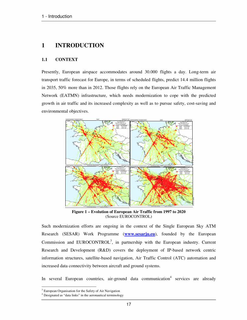
Presently, European airspace accommodates around 30.000 flights a day. Long-term air
transport traffic forecast for Europe, in terms of scheduled flights, predict 14.4 million flights
in 2035, 50% more than in 2012. Those flights rely on the European Air Traffic Management
Network (EATMN) infrastructure, which needs modernization to cope with the predicted
growth in air traffic and its increased complexity as well as to pursue safety, cost-saving and
environmental objectives.
Figure 1 – Evolution of European Air Traffic from 1997 to 2020 (Source EUROCONTROL)
Such modernization efforts are ongoing in the context of the Single European Sky ATM
Research (SESAR) Work Programme (www.sesarju.eu), founded by the European
Commission and EUROCONTROL3, in partnership with the European industry. Current
Research and Development (R&D) covers the deployment of IP-based network centric
information structures, satellite-based navigation, Air Traffic Control (ATC) automation and
increased data connectivity between aircraft and ground systems.
In several European countries, air-ground data communication4 services are already
3 European Organisation for the Safety of Air Navigation 4 Designated as “data links” in the aeronautical terminology
EUROCONTROL DIVISION DED4 1997 DATE:04/11/97
1997 FORECASTMean IFR Flights per day
in 6’ by 10’ rectangles
Flights 150 OR MOREFlights 100 TO 150Flights 50 TO 100
TRAFFIC DISTRIBUTION FORECAST ASSUMING FLIGHTS ON DIRECT ROUTES7 500 000 flights estimated Based on STATFOR 97
CH
AR
T: D
Y_97_97
EUROCONTROL DIVISION DED4 2000 DATE:04/11/97
2000 FORECASTMean IFR Flights per day
in 6’ by 10’ rectangles
Flights 150 OR MOREFlights 100 TO 150Flights 50 TO 100
TRAFFIC DISTRIBUTION FORECAST ASSUMING FLIGHTS ON DIRECT ROUTES8 600 000 flights estimated - Based on STATFOR 97
CH
AR
T: D
Y_
97
_0
0
EUROCONTROL DIVISION DED4 2010 DATE:04/11/97
2010 FORECASTMean IFR Flights per day
in 6’ by 10’ rectangles
Flights 150 OR MOREFlights 100 TO 150Flights 50 TO 100
TRAFFIC DISTRIBUTION FORECAST ASSUMING FLIGHTS ON DIRECT ROUTES11 900 000 flights estimated - Based on STATFOR 97
CH
AR
T: DY
_97_10
EUROCONTROL DIVISION DED4 2020 DATE:04/11/97
2020 FORECASTMean IFR Flights per day
in 6’ by 10’ rectangles
Flights 150 OR MOREFlights 100 TO 150Flights 50 TO 100
TRAFFIC DISTRIBUTION FORECAST ASSUMING FLIGHTS ON DIRECT ROUTES15 800 000 flights estimated - Based on STATFOR 97
CH
AR
T: DY
_97_20
1 - Introduction
18
operational. This infrastructure is under implementation to support Controller-Pilot Data Link
Communications (CPDLC), replacing voice exchanges between the cockpit and ground ATC,
using short messages to support routine communications. CPDLC applications include the
initiation of the communications service, ATC clearances (departure, climb and descent),
management of repetitive frequency changes and microphone check.
The technology of choice for CPDLC is compliant with the Aeronautical Telecommunications
Network (ATN)5 concept of the International Civil Aviation Organisation (ICAO) in the upper
part of the ICAO VHF aeronautical communications spectrum band (118 MHz to 138 MHz),
using the VHF Digital Link Mode 2 (VDL2) radio system. The implementation of this service
in Europe was subject of Single European Sky (SES) regulatory measures with ground
implementation and aircraft equipage mandated by the European Commission (EC) Regulation
29/2009 of 16 January 2009 on Data Link Services [1].
This initial development will be only the first step for the introduction of more advanced air-
ground data link technologies, designated as Future Communications Infrastructure (FCI) [2].
FCI is designed to sustain more demanding requirements.
FCI comprises three segments: a satellite-based data link system (SATCOM) for the oceanic,
remote and continental environments, an airport surface data link system, referred to as the
Aeronautical Mobile Airport Communications System (AeroMACS), and a terrestrial data link
system for continental airspace, referred to as the L-band Digital Aeronautical
Communications System (LDACS).
Aeronautical navigation is another fundamental aviation enabler. There is a need to determine
aircraft´s position, and to receive information that allows the pilot to steer and guide the
aircraft along the route to be flown.
Today, air transport operations rely on Navigation Aids (NAVAIDS) for position-
determination and to obtain ranging and bearing indications. On board, aircraft avionics are
able to calculate the aircraft’s position from the information received from those NAVAIDS.
The traditional ground-based NAVAID infrastructure [3] comprises: Non-Directional Beacon
(NDB), Very High Frequency Omnidirectional Ranging systems (VOR) and Distance
Measuring Equipment (DME). Today’s infrastructure includes also satellite constellations:
U.S. Global Positioning System (GPS), European GALILEO and the Russian GLONASS. The
5 described in Annex 10 to the ICAO Convention / Open Systems Interconnection

1 - Introduction
19
generic name for any satellite constellation used for positioning is Global Navigation Satellite
System (GNSS).
The introduction of GNSS raises the opportunity to rationalise the ageing ground-based
systems (e.g. NDB, DME and VOR). However, reliance of navigation being placed upon
signals from a satellite source, as the sole means, raises complex safety challenges: in fact, the
GNSS signals can be lost due to jamming or natural interference (e.g solar storm).
Consequently, there is a need to retain a fall back/back up terrestrial infrastructure, presently
based on DME, together with autonomous onboard navigation functions, like Inertial
Navigation Systems (INS), to mitigate GNSS outages and to ensure continued operations.
DME technology is now close to obsolescence and does not ensure adequate coverage to
support more advanced navigation concepts, e.g. multitrack Area Navigation / Random
Navigation (RNAV). It is also impacted by spectrum constraints in the band 960 MHz to 1215
MHz. Due to the previous reasons and also to facilitate the rationalization of aircraft equipage,
it is imperative to introduce Alternative Positioning Navigation and Timing (A-PNT)
technologies. The use of “pseudolites”, reutilization of surveillance equipment, for example
Secondary Surveillance Radar (SSR) Mode S, or reliance on data links to exchange ranging
and bearing / positioning information are amongst the A-PNT candidates to support such
aeronautical navigation functions and enable the gradual decommissioning of current VORs
and DMEs.
The present thesis discusses the feasibility of using the air-ground data link as A-PNT option
taking advantage of the emergence of the Future Communications Infrastructure (FCI)6
concept and further development of LDACS technology. Reference is also made to military
data links used today to sustain similar Relative Navigation (RELNAV) functions.
1.2 OBJECTIVE AND SCOPE
The main objective of this academic work is to discuss and describe an alternative solution for
aeronautical aircraft navigation based on the use of new data link technologies as a means of
A-PNT. This navigation solution shall contribute to the rationalization of the existing European
ground navigation infrastructure.
This work intends to demonstrate the feasibility of Future COM terrestrial data link, LDACS,
to replace DMEs in providing ranging and positioning information for aircraft navigation.
6 Also known as “Future COM”

1 - Introduction
20
A very important disclaimer is that the present thesis does not intend to discuss at length the
Orthogonal Frequency Division Multiplexing (OFDM) transmission technique and the
methodologies to address multipath, inter symbol and inter carrier interference. However, a
brief evaluation of the level of multipath mitigation/coherent detection improvements offered
by channel estimation is swiftly introduced based on some simulations to illustrate that
feasibility could be attained with the use of Kalman filters.
This document fulfils academic purposes. It shall not support directly any technical
implementation purposes. Additional standardisation or industrialisation activities would be
required. It references only information openly available and considered unclassified/non-
sensitive and not subject of any industrial copyright.
Intended readership comprises academic context and participants in aviation research activities
in telecommunications engineering and aeronautical technologies. The author developed this
work on private grounds without any link to any of his professional commitments within
EUROCONTROL.
1.3 DOCUMENT STRUCTURE
This document includes:
• Introduction – Setting the scene, providing background information and describing
the air transport and technological context.
• The Need for Alternative Positioning Navigation and Timing – Presenting
future navigation concepts and the justification for the introduction of different
technology solutions for navigation enabling the replacement of present ground-
based NAVAIDs. Distance Measuring Equipment technology is described.
• Air-Ground Data Link Technologies – Describing existing and future air-ground
data communications technologies with a particular focus on the LDACS data link.
• Relative Navigation – Presenting the objectives of RELNAV and describing the
current use of military data links to sustain RELNAV functions.
• Feasibility Assessment and Simulations – Recalling known results from previous
trials and specific simulations to validate improvements to the candidate A-PNT,
the LDACS OFDM data link, against the identified performance targets in terms of
ranging accuracy and position-determination.
• Conclusion – Summary of key findings, recommendations and opportunities.

2 – Aeronautical Navigation Infrastructure
21
2 AERONAUTICAL NAVIGATION INFRASTRUCTURE
2.1 TERRESTRIAL NAVIGATION INFRASTRUCTURE
Knowing an aircraft’s position in real time it is a fundamental element of aeronautical
navigation. Today, most aircraft have highly sophisticated integrated modular avionics using
position information from a variety of navigation sources (NAVAIDS), terrestrial or space-
based, to calculate the steering signals and autopilots to ensure that the aircraft follows the
desired track.
The traditional ground-based navigation infrastructure consists of NAVAIDS, introduced more
than 50 years ago, such as:
• Non Directional Beacon (NDB),
• Very High Frequency Omni-Directional Ranging Systems (VOR),
• Distance Measuring Equipment (DME),
• Tactical Air Navigation (TACAN) Equipment (for the military).
NDBs are low frequency radio transmitters of omni-directional signals used as an instrument
approach for airports and offshore platforms. NDBs are designated as Locator when used as a
replacement at a location where normally a 75 MHz Marker would be used as Middle Marker
(MM) or Outer Marker (OM) for Instrument Landing System (ILS), co-located with or used
instead of a 75 MHz marker beacon as part of an ILS-system. NDBs are currently planned for
gradual phase out.
VORs provide bearing information and are also planned for gradual decommissioning (with
the exception of a residual number required to support an advanced navigation specification
designated as RNAV-5) [4]. DME is often “paired” with VOR, ILS or Microwave Landing
System (MLS). When the pilot or flight computer selects the required VOR, ILS frequency or
MLS channel the corresponding DME channel is automatically selected.
2 – Aeronautical Navigation Infrastructure
22
VOR and DME/N or DME/P7 are ICAO radio-navigation systems that can be operated
independently or collocated (paired). VORs operate in the band 108 MHz to 111.975 MHz and
are susceptible to multipath interference from surrounding terrain, buildings, trees and power
lines. Consequently, when necessary, a replacement can be a Doppler VOR (DVOR)
transmitter, more resistant to multipath interference than the conventional one.
DME /N or DME /P provide for continuous and accurate indications in the cockpit
(interrogator) of the slant range distance from the ground (transponder) reference point to the
aircraft’s DME interrogator. DME /N or DME /P operate in the band 960 MHz to 1215 MHz
and are vulnerable to multipath effects; impacting both transponder and interrogator. Later in
this thesis, more details are included on the characteristics of DME.
TACAN is a radio-navigation system (960 MHz to 1215 MHz) considered the military
equivalent of civil VOR/DME that provides a pilot with the slant-range distance information,
like any DME, as well as optional azimuth (bearing) information, similar to a VOR. Many
TACANs are operated, or even owned, by civil air traffic service providers, providing to civil
and military aircraft azimuth and slant range distance information at appropriate locations.
Aircraft equipped with DME /N or DME /P interrogator may use a TACAN as DME
substitute. When TACAN is collocated with civil VOR stations it is designated VORTAC.
2.2 GLOBAL NAVIGATION SATELLITE SYSTEM (GNSS)
Today’s infrastructure supporting aeronautical navigation includes also the use of satellite
constellations comprising the U.S. Global Positioning System (GPS) / NAVSTAR, Russian
GLONASS and the European GALILEO, currently being deployed, and a number of
augmentation services which complement/correct signals-in-space. The generic designation for
the satellite constellations used for aviation is Global Navigation Satellite System (GNSS) [5].
GNSS is a worldwide position and time determination system, which includes the
abovementioned satellite constellations, to be operated through aircraft receivers (gradually
multiconstellation/multifrequency), and system integrity monitoring, augmented as necessary
to support advanced area navigation concepts.
• The GPS space segment is composed of twenty four satellites in six orbital
planes. The satellites operate near-circular 20.200 km (10.900 NM) orbits at
7 Distinction is made between DME /P - the distance measuring element of the MLS and DME /N - distance measuring equipment, primarily serving operational needs of en-route or TMA navigation.

2 – Aeronautical Navigation Infrastructure
23
an inclination angle of 55 degrees to the equator, and each satellite completes
an orbit in approximately 12 hours. The GLONASS space segment consists of
twenty-four operational satellites and several spares.
• GLONASS satellites orbit at an altitude of 19.100 km with an orbital period of
11 hours and 15 minutes. Eight evenly spaced satellites are arranged in each
of the three orbital planes, inclined 64.8 degrees and spaced 120 degrees apart.
• GALILEO constellation (still being deployed) when fully operational, will
comprise 30 satellites in Medium Earth Orbit (MEO) at an altitude of 23.222
km. The satellites will occupy each of three orbital planes inclined at an angle
of 56° to the equator. The satellites will be spread evenly around each plane
and will take about 14 hours to orbit the Earth.
Different levels of performance can be identified for each Galileo service. For
the GALILEO Open Service (OS) there are no particular integrity
requirements. The performances for horizontal positioning accuracy at 95%
for a dual-frequency receiver are 4 m for horizontal accuracy and 8 m for
vertical accuracy with a service availability of 99%.
For the GALILEO Safety of Life (SoL) and the GALILEO Public Regulated
Service (PRS), the performance requirements include stringent horizontal and
vertical accuracy, integrity, continuity and time to alert for different service
levels. The availability of the service should be 99.5% for both services.
GALILEO plans to be interoperable with other GNSS constellations. Users should be able to
receive position data with the same receiver from any of the satellites in any combination. By
offering dual frequencies as standard, GALILEO will deliver real-time positioning accuracy
down to the meter range. The combination of GALILEO and GPS signals in dual receivers will
open the door to new GNSS applications that require a higher level of precision than currently
available with GPS alone. From most locations, six to eight GALILEO satellites will be visible
which, in combination with GPS signals, will allow positions to be determined up to within a
few centimetres.
In conclusion, the present aviation policy on GNSS envisages a gradual reliance on satellite
navigation towards its possible use as a sole navigation service. For that it needs to be proven
as the most cost beneficial solution and that safety and security requirements are met. We will
see later on that, for the moment, the risk of GNSS outages still requires the retention of
2 – Aeronautical Navigation Infrastructure
24
backup terrestrial NAVAIDS. The vision for implementing this policy is based on the
combined use of signals coming from, at least, two constellations, each with diverse radio
frequencies. User receivers will process signals from different GNSS constellations in
combination with the so-called augmentations, which correct the original satellite signals
(differential correction). GNSS will be a fundamental enabler for the advanced navigation
concepts promoted by ICAO under the framework of the Performance Based Navigation
(PBN) concept.
The original design of satellite constellations did not aim at meeting aviation safety
requirements alone. Therefore, augmentation systems have been developed to meet this need,
providing integrity, improved accuracy and continuity. These augmentation systems either
reside on the aircraft, known as Aircraft Based Augmentation System (ABAS), or are based on
specifically deployed infrastructure. The European Geostationary Navigation Overlay Service
(EGNOS) provides continent-wide Space Based Augmentation System (SBAS) and Ground
Based Augmentation System (GBAS) supports precision approach.
2.3 ADVANCED CONCEPTS: PERFORMANCE BASED NAVIGATION (PBN)
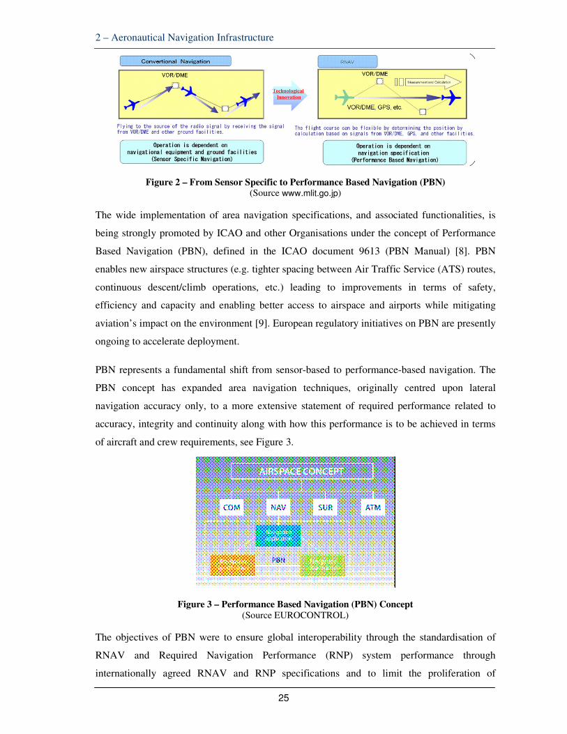
Already some decades ago, Area Navigation (also known as Random Navigation - RNAV) [6]
systems started to be introduced in aircraft avionics suites. RNAV uses signals from multiple
navigation aids to compute the position enabling aircraft to navigate along any desired route
independent from the location of the ground navigation aids. This separation of the route
structure from the location of navigation aids allowed new routes to be implemented without
new aids having to be installed.
RNAV definition describes it as a method, which permits aircraft navigation along any desired
flight path within the coverage of the associated navigation aids or within the limits of the
capability of self-contained aids [7], or a combination of these methods. RNAV equipment
includes any equipment that operates by automatically determining aircraft position from one
or a combination of sensors with the means to establish and follow a desired path. After the
designation RNAV it is normally added a figure identifying the lateral navigation performance
in nautical miles for 95% of the time (e.g. the specification RNAV-1 represents the ability to
fly with 1NM of lateral navigation performance 95% of the time), see Figure 2.
2 – Aeronautical Navigation Infrastructure
25
Figure 2 – From Sensor Specific to Performance Based Navigation (PBN) (Source www.mlit.go.jp)
The wide implementation of area navigation specifications, and associated functionalities, is
being strongly promoted by ICAO and other Organisations under the concept of Performance
Based Navigation (PBN), defined in the ICAO document 9613 (PBN Manual) [8]. PBN
enables new airspace structures (e.g. tighter spacing between Air Traffic Service (ATS) routes,
continuous descent/climb operations, etc.) leading to improvements in terms of safety,
efficiency and capacity and enabling better access to airspace and airports while mitigating
aviation’s impact on the environment [9]. European regulatory initiatives on PBN are presently
ongoing to accelerate deployment.
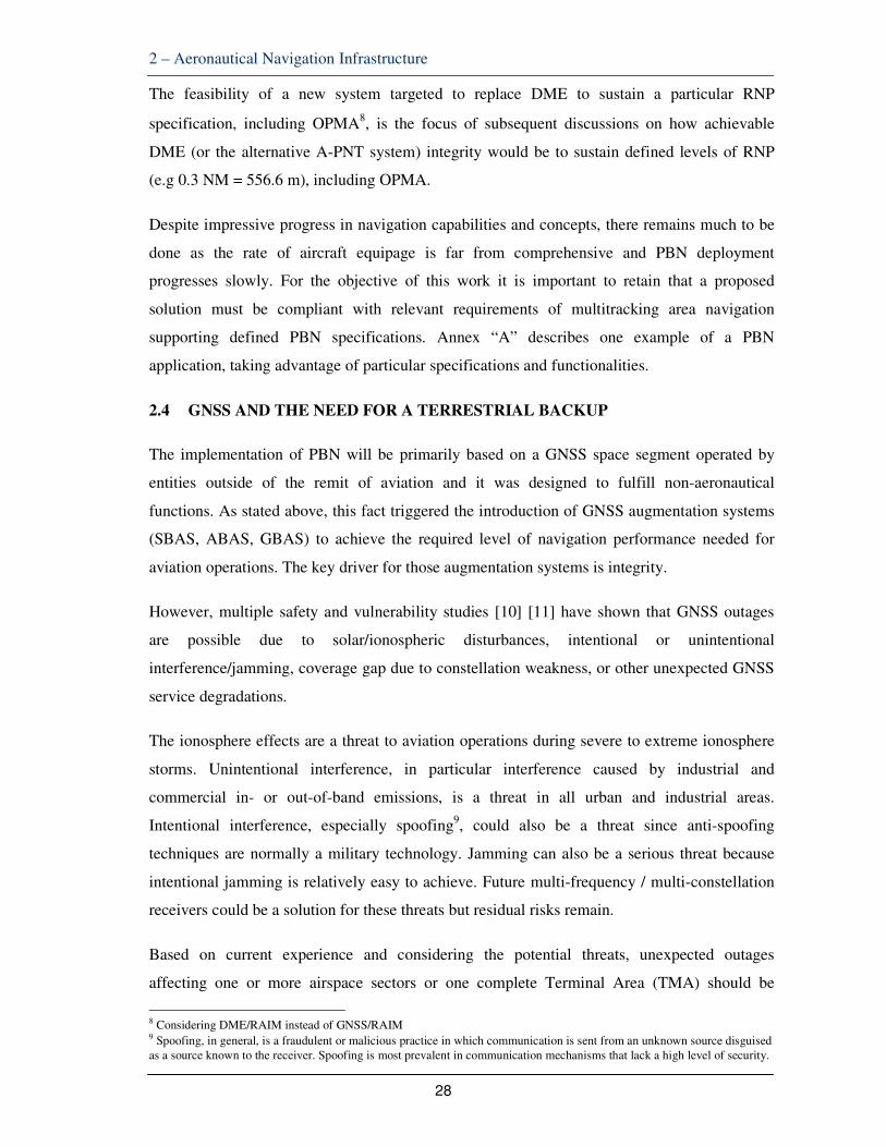
PBN represents a fundamental shift from sensor-based to performance-based navigation. The
PBN concept has expanded area navigation techniques, originally centred upon lateral
navigation accuracy only, to a more extensive statement of required performance related to
accuracy, integrity and continuity along with how this performance is to be achieved in terms
of aircraft and crew requirements, see Figure 3.
Figure 3 – Performance Based Navigation (PBN) Concept
(Source EUROCONTROL)
The objectives of PBN were to ensure global interoperability through the standardisation of
RNAV and Required Navigation Performance (RNP) system performance through
internationally agreed RNAV and RNP specifications and to limit the proliferation of

2 – Aeronautical Navigation Infrastructure
26
navigation specifications in use worldwide.
To support any airspace concept, along with Communications, Surveillance and ATM, PBN
relies in a three-component combination: A navigation application shall consist in the
implementation of a navigation specification and associated supporting navigation
infrastructure, applied to routes, procedures, and/or defined airspace volumes.
Navigation Application reflects the ATS routes and Instrument Flight Procedures (IFP) based
on the NAVAID Infrastructure and Navigation Specification.
Navigation Specification is a technical and operational specification that identifies the required
functionality of the onboard area navigation equipment. It also identifies how the navigation
equipment is expected to operate in the NAVAID Infrastructure to meet the operational needs
of the Airspace Concept. ICAO navigation specifications provide the basis for the States to
develop their certification and operational approval documentation. By the end of 2012, ICAO
has published 11 navigation specifications. The present thesis focus on PBN specifications and
the proposed solution targets the level of performance associated with some of those
specifications.
Navigation Infrastructure refers to ground- and space-based navigation aids.
PBN introduces two kinds of navigation specifications: RNAV and RNP. A fundamental
element of RNP specifications is the requirement for On-Board Performance Monitoring and
Alerting (OPMA) capability as depicted in Figure 4. This system alerts the pilot if navigation
performance requirements suffer any deviation.
Figure 4 – Difference Between RNAV and RNP
(Source EUROCONTROL)
RNAV specifications are effectively legacy specifications. Indeed, PBN’s sights are firmly set
on RNP, which relies primarily on the use of satellite technologies. The PBN Manual contains
11 navigation specifications: four of these are RNAV and seven are RNP specifications:

2 – Aeronautical Navigation Infrastructure
27
Figure 5 – PBN Specifications (Source EUROCONTROL)
For subsequent analysis we must retain the most demanding specification, RNP–0.3, closely
associated with RNP on Approach. It implies a lateral accuracy of 0.3 NM, or better, meaning
the need to ensure that the ranging error is lower than 556.6 meters.
The PBN Manual defines also the so-called “functionalities” (required or optional) which can
be used in association with several of the navigation specifications. It is the case, for example,
of Radius to Fix, RNAV Holding, Time of Arrival Control and Barometric Vertical Navigation
(Baro VNAV).
The final goal is for Advanced RNP specification to become the next European-wide
navigation specification used in enroute and terminal airspace, including the approach, missed
approach and departure phases of flights. Early drafts of the Advanced RNP specification
proposed the flexibility to choose one of a series of accuracy values in each flight phase; this
capability is a “Scalable RNP”.
It is essential to verify if DME infrastructure can support most PBN specifications, in particular
RNP. Multi-DME ranging provides an Area Navigation (RNAV) service with performances up
to at least 1NM accuracy (ideally 0.3 NM as previously stated). However, as currently defined,
DME/DME positioning may not support RNP navigation specifications that require OPMA
alerting. The high level goal of OPMA is to achieve a bound on Total System Error (TSE) at a
10-5 per flight hour integrity risk level.
2 – Aeronautical Navigation Infrastructure
28
The feasibility of a new system targeted to replace DME to sustain a particular RNP
specification, including OPMA8, is the focus of subsequent discussions on how achievable
DME (or the alternative A-PNT system) integrity would be to sustain defined levels of RNP
(e.g 0.3 NM = 556.6 m), including OPMA.
Despite impressive progress in navigation capabilities and concepts, there remains much to be
done as the rate of aircraft equipage is far from comprehensive and PBN deployment
progresses slowly. For the objective of this work it is important to retain that a proposed
solution must be compliant with relevant requirements of multitracking area navigation
supporting defined PBN specifications. Annex “A” describes one example of a PBN
application, taking advantage of particular specifications and functionalities.
2.4 GNSS AND THE NEED FOR A TERRESTRIAL BACKUP
The implementation of PBN will be primarily based on a GNSS space segment operated by
entities outside of the remit of aviation and it was designed to fulfill non-aeronautical
functions. As stated above, this fact triggered the introduction of GNSS augmentation systems
(SBAS, ABAS, GBAS) to achieve the required level of navigation performance needed for
aviation operations. The key driver for those augmentation systems is integrity.
However, multiple safety and vulnerability studies [10] [11] have shown that GNSS outages
are possible due to solar/ionospheric disturbances, intentional or unintentional
interference/jamming, coverage gap due to constellation weakness, or other unexpected GNSS
service degradations.
The ionosphere effects are a threat to aviation operations during severe to extreme ionosphere
storms. Unintentional interference, in particular interference caused by industrial and
commercial in- or out-of-band emissions, is a threat in all urban and industrial areas.
Intentional interference, especially spoofing9, could also be a threat since anti-spoofing
techniques are normally a military technology. Jamming can also be a serious threat because
intentional jamming is relatively easy to achieve. Future multi-frequency / multi-constellation
receivers could be a solution for these threats but residual risks remain.
Based on current experience and considering the potential threats, unexpected outages
affecting one or more airspace sectors or one complete Terminal Area (TMA) should be
8 Considering DME/RAIM instead of GNSS/RAIM 9 Spoofing, in general, is a fraudulent or malicious practice in which communication is sent from an unknown source disguised as a source known to the receiver. Spoofing is most prevalent in communication mechanisms that lack a high level of security.

2 – Aeronautical Navigation Infrastructure
29
“occasional” events. Such qualitative frequency of occurrence could be translated in a
quantitative frequency corresponding to an unexpected outage affecting one or more sectors
once every 1 to 10 years. However the likelihood for such event might be greater in TMA
because interference is more likely at low altitude.
As a consequence, there is broad agreement that some terrestrial navigation infrastructure
needs to remain operational in order to mitigate the risk of a potential wide area GNSS outage
enabling appropriate reversion scenarios.
2.5 ALTERNATIVE POSITIONING NAVIGATION AND TIMING (A-PNT)
The implementation of PBN is to be primarily based on GNSS. However, despite the
introduction of augmentation systems to improve GNSS integrity, the space segment remains
vulnerable to service outages due to jamming or solar events.
The abovementioned GNSS outages require the retention of alternative means for the provision
of Alternative Positioning, Navigation and Timing. Today´s decisions indicate that the first A-
PNT choice is the retention of existing conventional NAVAIDS like DME [12]. Initially, DME
will serve as the back up to mitigate unavailability of satellite navigation enablers without
prejudice of investigating other A-PNT means that fulfill RNAV and RNP requirements.
Essentially, an alternative navigational functionality suitable for PBN requires an aircraft to be
able to perform ranging to several known, typically ground-based ranging sources at known
locations. DMEs are one option but other alternatives shall not be discarded. DME stations are
often located along air-traffic corridors and, thus, their placement is not optimized for
multilateration.
Nevertheless, DME is still seen as the most suitable existing terrestrial navigation aid to sustain
PBN. For that, multi-DME ranging shall provide an RNAV service with a minimum
performance accuracy of 1 Nautical Mile (NM) (or ideally 0.3 NM). However, as currently
defined, DME/DME positioning may not be able to support RNP navigation specifications,
which require OPMA (e.g RNP-1 or RNP-0.3). For RNP-0.3 only GNSS enablers are suitable
today.
A key advantage of DME is that all system components are under aviation control. DME
ground transponders have evolved over many years of service and contain a number of
industry standard monitors, which are linked to specific ICAO Annex 10 requirements and
2 – Aeronautical Navigation Infrastructure
30
recommendations. These monitors detect anomalies and terminate service if required. Some
ANSP in Europe have imposed specific integrity monitoring and manufacturers have
consequently integrated them into their station designs.
Next, the signal in space propagation issues facing DME are generally well understood due to
the long and established service history of DME – there is the potential of multipath, co-
channel interference and other effects that can be controlled by a variety of ANSP efforts. This
is also true for the historically most prevalent DME error effect, the map-shift due to station
coordinate publication errors. Finally, aircraft interrogators and downstream Flight
Management System (FMS) processing does include reasonableness checks and in many cases
INS integration protects against several avionics-based failure modes, including DME ranging
errors.
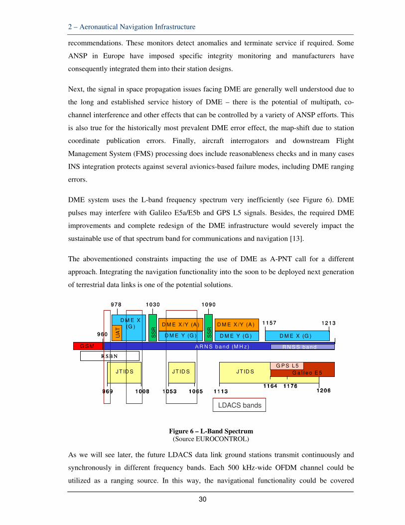
DME system uses the L-band frequency spectrum very inefficiently (see Figure 6). DME
pulses may interfere with Galileo E5a/E5b and GPS L5 signals. Besides, the required DME
improvements and complete redesign of the DME infrastructure would severely impact the
sustainable use of that spectrum band for communications and navigation [13].
The abovementioned constraints impacting the use of DME as A-PNT call for a different
approach. Integrating the navigation functionality into the soon to be deployed next generation
of terrestrial data links is one of the potential solutions.
Figure 6 – L-Band Spectrum (Source EUROCONTROL)
As we will see later, the future LDACS data link ground stations transmit continuously and
synchronously in different frequency bands. Each 500 kHz-wide OFDM channel could be
utilized as a ranging source. In this way, the navigational functionality could be covered
9 7 8 1 0 30 1 0 9 0
1 1 57 1 2 1 3
9 6 0 UA
T
SS
R
SS
R
D M E X(G )
D M E Y (G )
R N S S b a n d
D M E X /Y (A )D M E X /Y (A )
D M E Y (G )
A R N S b a n d (M H z)
9 6 9 1 0 0 8 1 0 5 3 1 0 6 5 1 1 1 31 1 64 1 1 76
1 2 0 6
JT ID S JT ID S JT ID S G a lile o E 5
G P S L 5
D M E X (G )
G S M
R S B N
9 7 8 1 0 30 1 0 9 0
1 1 57 1 2 1 3
9 6 0 UA
T
SS
R
SS
R
D M E X(G )
D M E Y (G )
R N S S b a n d
D M E X /Y (A )D M E X /Y (A )
D M E Y (G )
A R N S b a n d (M H z)
9 6 9 1 0 0 8 1 0 5 3 1 0 6 5 1 1 1 31 1 64 1 1 76
1 2 0 6
JT ID S JT ID S JT ID S G a lile o E 5
G P S L 5
9 6 9 1 0 0 8 1 0 5 3 1 0 6 5 1 1 1 31 1 64 1 1 76
1 2 0 6
JT ID S JT ID S JT ID S G a lile o E 5
9 6 9 1 0 0 8 1 0 5 3 1 0 6 5 1 1 1 31 1 64 1 1 76
1 2 0 6
JT ID S JT ID S JT ID S G a lile o E 5
G P S L 5
D M E X (G )
G S M
R S B N
LDACS bands

2 – Aeronautical Navigation Infrastructure
31
through the implementation of LDACS ground stations.
2.6 DISTANCE MEASURING EQUIPMENT (DME)
In accordance with ICAO Annex 10 Volume 1, DME is a transponder-based radio navigation
technology that provides a means of measurement of slant range distance from an aircraft to a
selected transponder. This information is available within the limit of coverage prescribed by
the operational requirements for the selected transponder. Such measurement considers the
propagation delay of transmitted signals. In summary: the purpose of the DME system is to
calculate how far an aircraft is from a selected ground transponder.
A complete DME system [14] comprises two main components: an interrogator (aircraft) and a
transponder (ground-based). The interrogator and transponder have similar main functional
elements: encoder, transmitter, receiver and decoder.
Figure 7 - DME principle (Source www.edn.com)
The aircraft interrogates the ground transponder with a series of pulse-pairs (interrogations)
and, after a precise time delay (typically 50 microseconds), the ground station replies with an
identical sequence of pulse-pairs (see Figure 7).
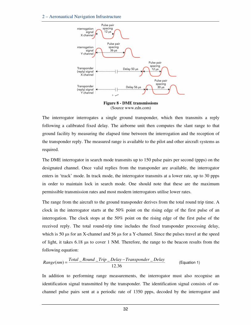
The DME transceiver in the aircraft searches for pulse-pairs (X-mode = 12 microsecond and
Y-mode = 36 microsecond spacing) with the correct interval between them, as shown in Figure
8, which is determined by each individual aircraft's particular interrogation pattern. The aircraft
interrogator locks on to the DME ground station once it recognizes that a particular reply pulse
sequence has the same spacing as the original interrogation sequence. Once the receiver locks,
it has a narrower window in which to look for the echoes and can retain lock.
2 – Aeronautical Navigation Infrastructure
32
Figure 8 - DME transmissions (Source www.edn.com)
The interrogator interrogates a single ground transponder, which then transmits a reply
following a calibrated fixed delay. The airborne unit then computes the slant range to that
ground facility by measuring the elapsed time between the interrogation and the reception of
the transponder reply. The measured range is available to the pilot and other aircraft systems as
required.
The DME interrogator in search mode transmits up to 150 pulse pairs per second (ppps) on the
designated channel. Once valid replies from the transponder are available, the interrogator
enters in ‘track’ mode. In track mode, the interrogator transmits at a lower rate, up to 30 ppps
in order to maintain lock in search mode. One should note that these are the maximum
permissible transmission rates and most modern interrogators utilise lower rates.
The range from the aircraft to the ground transponder derives from the total round trip time. A
clock in the interrogator starts at the 50% point on the rising edge of the first pulse of an
interrogation. The clock stops at the 50% point on the rising edge of the first pulse of the
received reply. The total round-trip time includes the fixed transponder processing delay,
which is 50 µs for an X-channel and 56 µs for a Y-channel. Since the pulses travel at the speed
of light, it takes 6.18 µs to cover 1 NM. Therefore, the range to the beacon results from the
following equation:
36.12
____)(
DelayrTranspondeDelayTripRoundTotalnmRange
−= (Equation 1)
In addition to performing range measurements, the interrogator must also recognise an
identification signal transmitted by the transponder. The identification signal consists of on-
channel pulse pairs sent at a periodic rate of 1350 ppps, decoded by the interrogator and

2 – Aeronautical Navigation Infrastructure
33
converted into an audible tone used by the pilot. The identification is a three or four letter
Morse Code, uniquely identifying the transponder to which the interrogator is tuned.
For the purpose of the present thesis, it is important to retain the following range-related
performance targets (focus on DME/N):
• Range. The system shall provide a means of measurement of slant range
distance from an aircraft to a selected transponder to the limit of coverage
prescribed by the operational requirements for the selected transponder.
• System accuracy. The accuracy standards specified in the ICAO Annex 10
shall be met on a 95% probability basis.
• DME/N. The transponder shall not contribute more than plus or minus 1
microsecond (150 m (500 ft)) to the overall system error.
• DME/N. The interrogator shall not contribute more than plus or minus 315 m
(plus or minus 0.17 NM) or 0.25% per cent of indicated range, whichever is
greater, to the overall system error.
• DME/N. The combination of the transponder errors, transponder location
coordinate errors, propagation effects and random pulse interference effects
shall not contribute more than plus or minus 185 m (0.1 NM) to the overall
system error. This error contribution limit includes errors from all causes
except the airborne equipment, and assumes that the airborne equipment
measures time delay based on the first constituent pulse of a pulse pair.
Figure 9 – VOR/DME Brussels Airport (Source BELGOCONTROL)

2 – Aeronautical Navigation Infrastructure
34
2.7 DME USE TO SUPPORT AREA NAVIGATION AND TO BACK UP GNSS
As stated before, there is no assurance that DME/DME can be fully recognized as the
reversionary capability to GNSS-based PBN operations that require RNP level of performance.
This could significantly boost the requirement to deploy new A-PNT systems using new
technology. Due to operational requirements foreseen for application in Europe, the present
discussion was still limited to RNP-1, e.g., RNP supporting a 1NM (95%) accuracy
performance.
DME evidences the following drawbacks for playing that role:
• Path Definition Error (PDE), Flight Technical Error (FTE), Navigation System
Error (NSE), described before;
• Malfunction of the transponder which leads to the insertion of a time delay
exceeding the specified tolerances (50μs ± 1μs in X mode or 56μs ± 1μs in Y
mode);
• Multipath effects including downlink multipath propagation which would
generate two replies to the same interrogation;
• Reply efficiency drop due to echoes coming from reflectors located in the
vicinity;
• Incorrect range information if the transponder replies to both direct path and
reflected path interrogations.
DME Errors - The high level objective of OPMA is to achieve a bound on Total System Error
at 10-5 per flight hour integrity risk level. The TSE is composed of Path Definition Error
(PDE), Flight Technical Error (FTE) and Navigation System Error (NSE).
While the PDE is considered negligible, it should be noted that this is enabled by specific
avionics functions, namely Fixed Radius Turn (FRT) in the en-route and radius to fix (RF) in
the terminal area. These two functions eliminate the path dispersion between route segments,
which is typical due to different configurations of aircraft aerodynamics and weight. Without
those functions, PDE becomes essentially unbounded over the turns.
FTE depends on the level of aircraft automation – procedure design distinguishes between

2 – Aeronautical Navigation Infrastructure
35
hand-flown FTE and FTE using an autopilot or flight director. Manually flown FTE has been
assumed to achieve accuracies limited to an error of 0.5 NM at a 95% confidence level in
RNAV-1 applications. Earlier work has documented Automatic Flight Control System
(AFCS)-coupled FTE at a maximum value of 0.22NM when using DME/DME.
Moving on to NSE, the integrity budget for RNP-1 has been specified to require an alert at a
10-7 risk level when exceeding twice the RNP value, e.g., 2NM. This is easily met by all
current generation GNSS avionics. This will also be sufficient to meet the high level RNP goal
of a 10-5 TSE bound which includes NSE support to limiting the FTE distribution.
Malfunction of the transponder - The DME slant range is computed by the interrogator based
on the propagation delay to and from the transponder, taking into account a fixed delay which
is introduced by the latter. As such, in an interrogator fault free scenario, the only integrity
threat consists in a corrupted delay of the reply pulses. There are 2 main causes that could
affect this delay: Downlink multipath propagation or malfunction of the transponder which
leads to the insertion of a time delay exceeding the specified tolerances (50μs ± 1μs in X
mode or 56μs ± 1μs in Y mode). The last problem is addressed through internal transponder
monitoring mechanisms to ensure that transponder faults are kept within a certain limit.
Multipath - DME multipath signals, received at the airborne DME interrogator, shall not have
an adverse impact on signal quality and the resulting distance accuracy. However, some tests
revealed the duration of multipath received at airborne receiver to be about 150 µs in length
and only about 25 dB weaker then the direct signal. Multipath effect on DME transponder
receiver can cause false replies mainly if aircraft are less than 25 NM separated from a
transponder. That is logical since the path loss increases with distance, which in consequence
provides a faster drop of the amplitude of the received multipath signals below the noise floor.
This effect is mitigated through the application of dead time with variable length after each
reply generated by a valid interrogation pulse pair to avoid false replies to that can be caused
by delayed signals due to multipath.
While downlink multipath is much more significant it can also be more effectively be
mitigated by the ground facility as discussed previously. Due to the motion of the aircraft and
the constraints in reflector geometry (e.g., a significant reflection surface is required for
sufficient pulse energy to reach the aircraft), uplink multipath is essentially noise-like. While
some isolated cases of confirmed uplink multipath have been reported, these remain rare and
small in magnitude. In an analysis of multiple DME facilities received over a large number of
2 – Aeronautical Navigation Infrastructure
36
flight test tracks, it has been demonstrated that the DME 95% range accuracy lies within 0.05
NM. This provides a suitable bound for both nominal noise and uplink multipath performance.
However, it should also be noted that this analysis shows distribution deviations up to 0.2 NM
which require further investigation.
The measure required by the ICAO Annex 10 to prevent multipath effects is the introduction of
a “DME dead time: a period immediately following the decoding of a valid interrogation
during which a received interrogation will not cause a reply to be generated”. The dead time is
normally set to 60 µs. The 60 µs interval already prevents the decoding of echoes with a
propagation path difference up to 10 NM. It is obvious that reflected interrogation with a delay
higher than 60 s can only be produced by extremely large reflectors (i.e. natural terrain features
like mountain sides).
The probability of echoes with a higher propagation delay appears to be very low; however,
transponders generally comply with the recommended capability to reject long distance echoes
arriving with a delay up to at least 120 s. The increase of the dead time may impact on the
other hand the reply efficiency. For this reason several rejection techniques may be used (e.g.
only signals with the power level several dB below the valid interrogation are rejected in the
extended dead time, or a variable duration dead time window is used).
The risk of receiving another DME beacon reply far away that has been allocated to the same
channel appears to be one of the most relevant threats to DME-based positioning integrity, with
the potential to lead to significant range measurement errors, particularly if the desired station
is out of service.
Additional noise from TACAN is not considered to be relevant from a range error perspective
and is normally filtered out especially when considering the normal resolution of avionics
DME range outputs (resolution is typically not greater than 0.01NM or 18m), but may have an
impact on the ability of avionics to detect errors.
Reply efficiency drop - This effect may appear due to echoes coming from reflectors located
relatively close to the ground stations so that the additional time delay is less than the
interrogation pulse spacing (12μs ± 0.25μs in X mode respectively 36μs ± 0.25μs in Y
mode). In this case the decoder would detect a spacing value that is out of tolerance and would
reject the interrogation. Recent flight test evidence supports that this short distance echo
suppression mechanism is working well. Although this may cause a continuity issue, it is not
considered a threat to integrity.

2 – Aeronautical Navigation Infrastructure
37
Incorrect range information - This type of issue may appear if the transponder replies both to
direct path and reflected path interrogations. In this case, in certain circumstances the
interrogator may lock onto the second set of replies in which case the calculated range will be
higher than the real one. The mitigation measures implemented in the transponder in order to
cater for this potential integrity issue are described below.
The acceptable DME/N overall system error (which determines the acceptable range
performance) results from the interrogators and transponder cumulative contributions identified
above: 185 m (0.1 NM) + 315 m (0.17 NM) = 400m (0.27 NM). ICAO Annex 10 describes the
full set of DME technical parameters and filters used to maximize performance.
It is important to stress again that Inertial Navigation System integration can protect against
several avionics-based failure modes, including DME ranging errors.
There is a risk is that the aviation community may reject DME/DME as a reversionary backup
capability to GNSS-based PBN operations which require RNP performance. This could
significantly diminish the future value of the significant levels of fielded equipage, both on
aircraft and on the ground. It will also firm up the requirement to deploy new A-PNT systems
using new technology.
3 – Air-Ground Data link Technologies
38
3 AIR-GROUND DATA LINK TECHNOLOGIES
3.1 CURRENT TECHNOLOGIES
Air ground VHF voice communications10 remains a key enabler for the exchange of
information and instructions between the aircraft and ground ATC. Voice is still the primary
means for pilots to communicate with air traffic controllers.
This form of analogue communications is now reaching its operational limits and the aviation
community started to implement air-ground digital data communications (thereafter designated
“data links”) to support and, at a later stage, replace voice as the primary means of ATC
communication. Voice remains available only for emergencies.
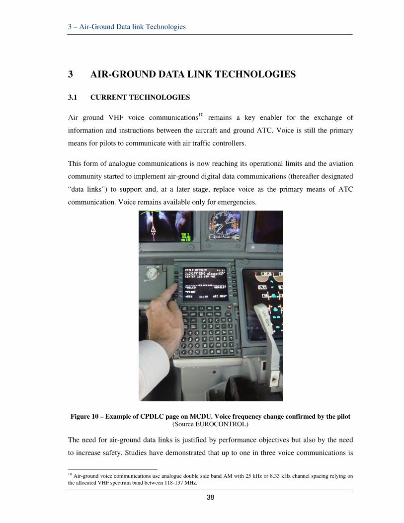
Figure 10 – Example of CPDLC page on MCDU. Voice frequency change confirmed by the pilot (Source EUROCONTROL)
The need for air-ground data links is justified by performance objectives but also by the need
to increase safety. Studies have demonstrated that up to one in three voice communications is
10 Air-ground voice communications use analogue double side band AM with 25 kHz or 8.33 kHz channel spacing relying on the allocated VHF spectrum band between 118-137 MHz.

3 – Air-Ground Data link Technologies
39
misunderstood and that controllers spend up to 50% of their time talking to pilots.
Data links connect pilots to controllers to support routine communications (exchange of pre-
defined short messages). In the context of ATC this is called Controller-Pilot Data Link
Communications (CPDLC). CPDLC11 sustains applications12 like the initiation of the
communications service, ATC clearances (departure, climb or descent), management of
repetitive frequency changes and microphone check. This service is already operational in
some of the European core-area states. Subsequently, additional applications to support
trajectory management will need the Automatic Dependant Surveillance – Contract (ADS-C)
technique relying also on the use of VDL Mode 2 [15].
Later, there are plans to implement ATC applications supporting the uplink of Aeronautical
Information Services (AIS) and Meteorology. Other applications will become operational for
Airport Services, Airline Operational Communications (AOC) and Airline Passenger
Communications (APC).
CPDLC relies on communications architectures, services and protocols compliant with the
ICAO Aeronautical Telecommunications Network (ATN) initially using Open System
Interconnection (OSI) protocol stack. Subsequently, ATN will use the Internet Protocol Suite
(IPS) as described in ICAO document 9896 [16].
Data link equipment like the Aircraft Communications and Reporting System (ACARS) or the
VHF Data Link Mode 2 are technologies in the VHF band used today to support CPDLC. The
latter is the choice for deployment in Europe and it was subject of SES regulatory measures
with ground implementation and aircraft equipage mandated by the European Commission
Regulation 29/2009 of 16 January 2009 on Data Link Services. The companies ARINC and
SITA are the main CPDLC service providers worldwide.
VDL2 radio technology relies on spectrum in the upper part of the band 118-138 MHz. The
VDL Mode 2 Link Layer comprises two sublayers, a data link service and a Medium Access
Control (MAC) sublayer. The data link protocol relies on the ISO standards used for dial-up
HDLC access to X.25 networks. It provides aircraft with a positive link establishment to a
ground station and defines an addressing scheme for ground stations. The MAC protocol is a
version of Carrier Sense Multiple Access (CSMA). The VDL Mode 2 Physical Layer specifies
11 It is of utmost importance not to mix the ATC applications and messages (normally standardised at EUROCAE/RTCA level), further described later in this chapter, with the data link technology infrastructure that supports information exchange. 12 Applications in this context means message formats and protocols standardised by EUROCAE
3 – Air-Ground Data link Technologies
40
the use in a 25 kHz wide VHF channel of a modulation scheme called Differential 8-Phase-
Shift-Keying with a symbol rate of 10.500 symbols per second. The raw (uncoded) physical
layer bit rate is 31.5 kbit/s; clearly insufficient to support future requirements.
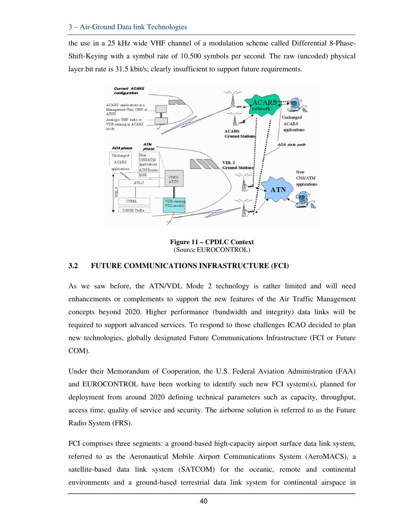
Figure 11 – CPDLC Context (Source EUROCONTROL)
3.2 FUTURE COMMUNICATIONS INFRASTRUCTURE (FCI)
As we saw before, the ATN/VDL Mode 2 technology is rather limited and will need
enhancements or complements to support the new features of the Air Traffic Management
concepts beyond 2020. Higher performance (bandwidth and integrity) data links will be
required to support advanced services. To respond to those challenges ICAO decided to plan
new technologies, globally designated Future Communications Infrastructure (FCI or Future
COM).
Under their Memorandum of Cooperation, the U.S. Federal Aviation Administration (FAA)
and EUROCONTROL have been working to identify such new FCI system(s), planned for
deployment from around 2020 defining technical parameters such as capacity, throughput,
access time, quality of service and security. The airborne solution is referred to as the Future
Radio System (FRS).
FCI comprises three segments: a ground-based high-capacity airport surface data link system,
referred to as the Aeronautical Mobile Airport Communications System (AeroMACS), a
satellite-based data link system (SATCOM) for the oceanic, remote and continental
environments and a ground-based terrestrial data link system for continental airspace in

3 – Air-Ground Data link Technologies
41
general, referred to as the L-Band Digital Aeronautical Communications System (LDACS).
Taking into account the identified requirements, several candidate technologies for the FRS
(Satellite Communications, Terrestrial Wideband CDMA, Cellular Telephony, UMTS, TDMA,
Software Defined Radios, Broadband VHF, etc.) were assessed and the most promising ones
would be analysed in detail and prototyped.
Figure 12 – Future Communications Infrastructure (FCI)
(Source EUROCONTROL)
The terrestrial component of FCI, LDACS, relies on spectrum allocations (960-1215 MHz)
agreed at the level of the International Telecommunications Union (ITU) and it is still being
subject of industrial research, in the context of the SESAR work programme, to determine the
final technology solution to be chosen between Frequency Division Duplex (FDD) utilizing
OFDM modulation and Time Division Duplex (TDD) combined with Gaussian Minimum Shift
Keying (GMSK)13 modulation.
3.3 L-BAND DIGITAL ATM COMMUNICATIONS SYSTEM (LDACS)
ICAO selected two candidate terrestrial technologies for the future digital air-ground
communications system. These technologies have been designated: LDACS1 and LDACS2.
LDACS2 is based on Global System for Mobile Communications (GSM). It is a narrowband
single-carrier system with 200 kHz transmission bandwidth and time-division duplex.
The present thesis focuses on LDACS1, as it is clearly the option retained for further
13
GMSK is a continuous-phase frequency-shift keying modulation scheme. It is similar to standard minimum-shift keying (MSK); however the digital data stream is first shaped with a Gaussian filter before being applied to a frequencymodulator.

3 – Air-Ground Data link Technologies
42
development. LDACS1 is based on OFDM waveform, which is a state-of-the-art broadband
waveform, resistant to multipath propagation and scalable to high-capacities, similar to the
waveforms currently used in broadband systems like wireless Local Area Networks (LAN)
(Wi-Fi), Long-Term Evolution (LTE) [17] and WiMAX (IEEE 802.16) [18], as well as in
digital broadcast systems (DAB, DVB-T, DVB-S). LDACS benefits from the European B-
VHF project, U.S. TIA-902 (P34) and WiMAX technologies. OFDM uses orthogonally
overlapped sub-carriers, each of which conveys part of the data (hence, each sub-carrier
operates under narrow-band condition and is naturally immune to multipath effects). The
forward and reverse channels operate under a FDD scheme.
In order to avoid sharing this limited bandwidth between forward and reverse links, frequency-
division duplex is applied. Note that the link from the ground station to the aircraft is referred
to as forward link, and the link back from the aircraft to the Ground Station (GS) is called
reverse link. LDACS1 offers two modes of operation, one for air-ground (A/G)
communications and another one for air-air (A/A) communications. These two modes use
different radio channels.
LDACS1 operating in the A/G mode is a cellular point-to-multipoint system. The A/G mode
assumes a star-topology where Airborne Stations (AS) belonging to aircraft within a certain
volume of space (the LDACS1 cell) are connected to the controlling GS. The LDACS1 GS is a
centralized instance that controls the LDACS1 A/G communications. The LDACS1 GS can
simultaneously support multiple bi-directional links to the ASs under its control.
Figure 13 – LDACS1 Topology (Source www.lit.lnt.de)
In order to maximize the capacity per channel and to optimally use the available spectrum,
LDACS1 is defined as an OFDM-based FDD system, supporting simultaneous transmission in

3 – Air-Ground Data link Technologies
43
Forward Link (FL) and Reverse Link (RL) channels, each with an occupied bandwidth of
498.05 kHz. Within that bandwidth 50 OFDM sub-carriers are placed separated by 9.765625
kHz. Each sub-carrier is separately modulated, the total duration of each modulated OFDM
symbol is Ts= 120 µs. The OFDM parameters have been selected taking into account specifics
of an aeronautical mobile L-band channel.
LDACS1 A/G design includes propagation guard times sufficient for the operation at a
maximum distance of 200 NM from the GS. At this distance, one-way propagation delay is
1.26 ms, roughly corresponding to the duration of 10 LDACS1 OFDM symbols. Large target
operational coverage imposed some constraints upon the LDACS1 PHY layer design
(definition of PHY frames). In a practical deployment, LDACS1 can be designed for any range
up to this maximum range.
The LDACS1 framing structure (Figure 14) for FL and RL is based on Super-Frames (SF) of
240 ms duration. Each SF corresponds to 2000 OFDM symbols. The FL and RL SF boundaries
are aligned (from the view of the GS).
Figure 14 - LDACS1 Framing Structure (Source [22])
In the FL, an SF contains a Broadcast Frame (BC) of duration TBC = 6.72 ms (56 OFDM
symbols), and four Multi-Frames (MF), each of duration TMF = 58.32 ms (486 OFDM
symbols). Each MF contains 9 Data/CC frames with a frame duration of TDF/CC = 6.48 ms
(54 OFDM symbols). Each Data/CC frame has a total data capacity of 2442 symbols and
comprises exactly three FL PHY-PDUs that are used for transmitting either the common
control (CC) information or payload data.
In the RL, each SF starts with a time slot of length TRA = 6.72 ms with two opportunities for
sending Reverse Link Random Access (RL RA) frames, followed by four MFs. These MFs

3 – Air-Ground Data link Technologies
44
have the same fixed duration of TMF = 58.32 ms as in the FL, but a different internal structure.
Within the RL MF, instead of frames, data and control (DC) segments are used that are further
divided into tiles. A tile spans a specified number of contiguous symbols, both in frequency
and time direction. The size of an RL Data PHY-PDU and an RL DC PHY-PDU corresponds
to the number of modulated data symbols of a corresponding DC/Data tile.
LDACS1 is intended to operate as a FDD system in the lower part of the L-band (960-1164
MHz). An airborne LDACS1 system (AS) using FDD with a single airborne antenna relies
upon an airborne TX/RX duplexer. Due to the duplexer feasibility, the blocks of FL and RL
channels must be sufficiently separated in frequency domain. 40 MHz has been assumed to be
the minimum practical width of a transition area for an airborne duplexer. This value should be
confirmed. Larger transition areas above 40 MHz (and larger duplex spacing above 63 MHz)
are considered feasible as well. Several options are still under discussion for the deployment of
LDACS1 in the lower part of L-Band [19] [20].
Figure 15 – Insertion of LDACS1 in the L-Band (Source IEEE Journal)
When operating in A/A mode, the LDACS1 system offers a broadcast A/A surveillance link
and an addressed (point-to-point) A/A data link, both with direct air-air connectivity. A/A
communication, between involved LDACS1 AS, takes place in a decentralized, self-organised
way without any need for ground support (GSs may be optionally deployed, e.g. for monitoring
A/A traffic). For A/A network synchronization purposes, the availability of a common global
time reference is assumed at each AS. No A/A voice services are offered in this mode.
LDACS1 operating in A/A mode assumes a dedicated global RF resource, the "Common
Communications Channel" (CCC). The LDACS1 A/A mode uses an OFDM-based physical

3 – Air-Ground Data link Technologies
45
layer with parameters (e.g. subcarrier spacing) different than those used for the A/G mode. As
it will be seen later, this feature of LDACS1 will be essential for an innovative proposal for a
navigation function to be supported.
LDACS1 is expected to provide coverage of up to 200 NM, corresponding to a cell radius of
approximately 370 km. This leads to large propagation delays of up to 1.2 ms. Particularly in
the case of an unsynchronized transmission sufficiently large guard times have to be foreseen
in the system design. In addition, such a large coverage area results in a high number of users
(i.e., aircraft active within a cell).
LDACS1 has to support very high user mobility leading to large Doppler shifts. The expected
maximum aircraft velocity of 1080 km/h leads to a Doppler shift of approximately 1 kHz
assuming a radio carrier frequency of 1 GHz. If aircraft fly in opposite directions, their
messages may arrive with a frequency offset of 2 kHz at a ground station. To relieve this issue,
appropriate guard bands or frequency pre-compensation have to be foreseen. Although the
Doppler shifts might be very high, only slight Doppler spreads are expected due to a strong line
of sight path.
To set up the cellular LDACS1 concept, adjacent cells use different paired transmission
channels for forward and reverse links. Cells farther apart might reuse already assigned
channels if interference towards other LDACS1 cells is negligible. To establish
communication, an aircraft has to register at the ground station of the respective LDACS1 cell.
For this cell entry, LDACS1 provides periodically occurring random access opportunities in
the reverse link. Due to the potentially large propagation delays, they are protected by
appropriate guard times.
After cell entry, the controlling ground station assigns a dedicated control channel to the
aircraft. This dedicated control channel guarantees timely channel access for the aircraft, which
is important for the latency requirements of ATM services. In addition, the ground station
measures the propagation delay and frequency offset of the random access messages during
cell entry. These values are conveyed to the aircraft to enable pre-compensation of the time and
frequency offset at the aircraft.
In this way, messages of all aircraft arrive synchronously at the ground station despite the
possibly large propagation delays and frequency offsets. No further guard times and bands are
required. Besides cell entry by means of random access opportunities, LDACS1 provides a
seamless handover procedure for already registered aircraft passing from the current to an

3 – Air-Ground Data link Technologies
46
adjacent cell. This is possible because the ground stations are synchronized with each other.
The seamless handover enables continuous communications between ground station and
aircraft, and relieves usage of random access opportunities.
LDACS1 achieves net data rates from 561 kbit/s (strong coding, robust modulation) to 2.6
Mbit/s (weak coding, higher order modulation) for a pair of forward and reverse link channels
(Table 1).
To account for a varying number of active aircraft and the current demand for user data
transmission, the size of the control and data segments is variable. Furthermore, resources for
the different users are dynamically assigned according to the current demand. To provide the
required granularity for the mostly short ATM messages, the reverse link framing is subdivided
into small tiles as explained before. An arbitrary number of these small tiles can be aggregated
and assigned to an aircraft depending on the actual message size. This is no issue in the
forward link, since multiple messages intended for different aircraft are grouped and
broadcasted to all aircraft. Each aircraft receives the entire frame and extracts its message.
Table 1 – Summary of Main LDACS1 Parameters (Source [22])
Strong channel coding is applied by concatenating Reed-Solomon and convolutional coding
schemes. To account for changing interference and channel conditions as well as different

3 – Air-Ground Data link Technologies
47
message priorities, LDACS1 supports adaptive coding and modulation. In the case of strong
interference or high-priority messages, a low coding rate and robust modulation scheme is
chosen, such as Quadrature Phase Shift Keying (QPSK). For favorable transmission
conditions, a high coding rate and/or higher order modulation, such as 16- or 64-Quadrature
Amplitude Modulation (QAM), can be used to increase the transmission capacity.
It is very important for the subsequent analysis to mention that the initial LDACS1
specification [21] [22] indicated the need to reach a Bit Error Rate (BER) of 10-6 or less after
Forward Error Correction (FEC). Although that BER is not directly associated with ranging
performance, it is assumed in the present thesis that it will solve the multipath/Doppler shift
problems enabling accuracies far better than the 556.6 meters required for RNP-0.3 (see further
details in section 5).
3.4 OTHER DATA LINK TECHNOLOGIES
To support surveillance applications where transmission delay (latency) is more stringent, there
is also a requirement for the introduction of broadcast data links to sustain the Automatic
Dependent Surveillance–Broadcast (ADS-B) technique. The selected broadcast datalink for
ADS-B in Europe is the Mode S 1090 MHz Extended Squitter and in U.S. a combination of
Mode S 1090 MHz Extended Squitter (global system for ADS-B) and Universal Asynchronous
Transceiver (UAT).
In other regions of the world point-to-point data link technologies are used, as it is the case of
services based on ARINC 622 (FANS1/A) specifications [23]. In some northern European
regions, the VHF Data Link Mode 4 (VDL-4) is used.
Out of such additional technologies, only Mode S is under investigation to determine its
suitability to be reutilised as a means of A-PNT. This new technology designates as Mode N. It
is not considered in the present thesis as it would rely on 1030/1090 MHz, which are frequency
channels close to reach saturation.

4 – Relative Navigation (RELNAV)
48
4 RELATIVE NAVIGATION (RELNAV)
4.1 RELNAV CONCEPT
The objective of Relative Navigation is to determine the distance between two or more
communication terminals by measuring the arrival times of the transmissions and correlating
with reported positions. That problem involves the need for automatic, reliable and accurate
relative positioning of two moving vehicles or one vehicle when referenced to ground based
radio sites.
A Kalman filter [24] (see annex B) can be used for estimating the relative position and
attitude14 of two air vehicles, designated leader and follower. All leader states are assumed
known, while the relative states are estimated using line-of-sight measurements between the
vehicles along with acceleration and angular rate measurements of the follower.
4.2 RELNAV ENABLED BY MILITARY DATA LINKS (MIDS/LINK 16)
The military data link JTIDS/MIDS15 Link 16 is a type of military tactical data exchange
network widely used by many military organisations. With Link 16, military aircraft as well as
ships and ground forces may exchange tactical picture in near-real time. Link 16 supports the
exchange of text messages, imagery data and provides two channels of digital voice. Link 16 is
defined as one of the digital services of the NATO's Multifunctional Information Distribution
System (MIDS) which technical characteristics are described in the Standardization Agreement
STANAG 4175 and message set in STANAG 5516.
Link 16 uses the Time Division Multiple Access (TDMA) technique that divides time into
discrete time slots to provide multiple and apparently simultaneous communication channels.
The MIDS data terminal is the communications component of Link 16. This type of network is
very difficult to organize and manage due to the static assignment of time slots and, as a result,
there are different Link 16 network settings for specific missions or areas of operation.
A group of radio terminals, using a frequency hopping technique that allows data transmission
over the available 51 different career frequencies, composes the Link 16 network. This TDMA
14 Not to confuse with “altitude”. In the aeronautical context “attitude” means: orientation of an aircraft's axes relative to a reference line or plane, such as the horizon. Given by the attitude indicator (AI) 15 Joint Tactical Information Distribution System / Multifunctional Information Distribution System
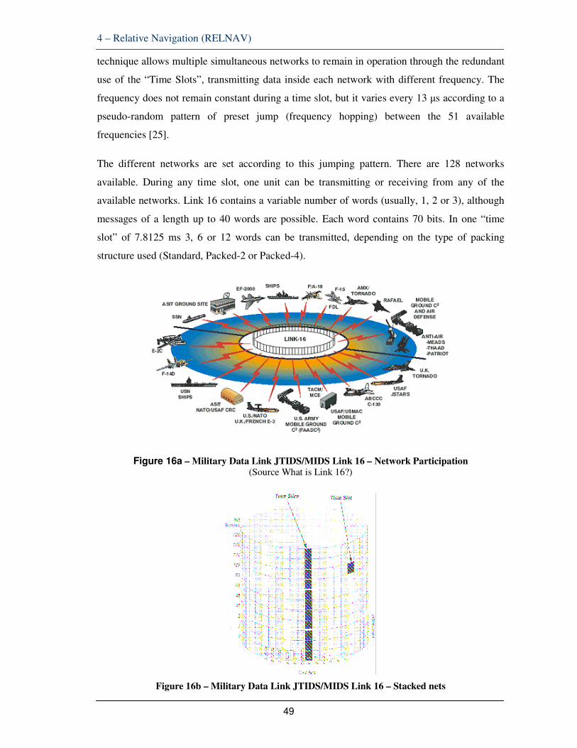
4 – Relative Navigation (RELNAV)
49
technique allows multiple simultaneous networks to remain in operation through the redundant
use of the “Time Slots”, transmitting data inside each network with different frequency. The
frequency does not remain constant during a time slot, but it varies every 13 µs according to a
pseudo-random pattern of preset jump (frequency hopping) between the 51 available
frequencies [25].
The different networks are set according to this jumping pattern. There are 128 networks
available. During any time slot, one unit can be transmitting or receiving from any of the
available networks. Link 16 contains a variable number of words (usually, 1, 2 or 3), although
messages of a length up to 40 words are possible. Each word contains 70 bits. In one “time
slot” of 7.8125 ms 3, 6 or 12 words can be transmitted, depending on the type of packing
structure used (Standard, Packed-2 or Packed-4).
Figure 16a – Military Data Link JTIDS/MIDS Link 16 – Network Participation (Source What is Link 16?)
Figure 16b – Military Data Link JTIDS/MIDS Link 16 – Stacked nets

4 – Relative Navigation (RELNAV)
50
(Source SESAR 15.2.8)
Figure 17 – Military Data Link JTIDS/MIDS Link 16 – Equipment and HMI (Source What is Link 16?)
In the military context, relative navigation [26] is an automatic function of the military data
link (JTIDS/MIDS Link 16) terminal, used to determine the distance between platforms by
measuring the arrival times of transmissions and correlating them with reported positions. This
information is required for the terminals in a network to remain synchronized.
Automatic RELNAV is permanently available in all airborne terminals, providing information
critical for synchronization. This RELNAV data improves unit's positional accuracy. If two or
more units have accurate and independent knowledge of their geodetic positions, RELNAV
can provide all units of the network with accurate geodetic positions. As a result, the precise
geodetic position of every unit can be permanently available at every other unit.
RELNAV function is inherent to the TDMA architecture and the synchronization process.
Each airborne terminal continuously calculates its own position by measuring the Times of
Arrival (TOA) of all received Precise Participant Location Information (PPLI) messages. As
such, RELNAV allows the terminal to calculate an accurate value for the range between itself
and another Link 16 transmitting unit. This very accurate range measurement is possible
because of the precise timing the terminal must maintain after achieving synchronisation with
the network.
The following figure (18) illustrates how the terminal calculates its own relative position. First,
consider a terminal that receives a PPLI from another unit. The upper left part of the figure
represents a PPLI received from a single source. From the PPLI´s TOA, the receiver can
calculate that its position is somewhere on the circle whose radius is the calculated range. In
the upper right of the figure, the position source has also provided a value for Position Quality
(Qp) in its PPLI. From the TOA and the Qp the receiver can calculate that its own position is
somewhere within the outer ring shaded area of the circle, and its range is somewhere between

4 – Relative Navigation (RELNAV)
51
the inner and outer edges of the shaded ring whose width defines its position uncertainty.
Figure 18 – Link 16 Range Calculation Process
The figure shows the process by which a Link 16 terminal calculates its range and range
uncertainty from one or more units. The greater the number of units from which a terminal
receives PPLIs, and the higher their reported position qualities are, the more accurately the
terminal can calculate its range from them, as well as its own position relative to them.
Now consider a terminal that receives PPLIs from two units. As shown in the lower left part of
the figure, the terminal can calculate that it is located at one of two positions where the two
range circles intersect. With a rough knowledge of position, the terminal can then decide which
one is correct.
Receiving PPLIs from additional units further contributes to the terminal´s position accuracy.
The lower right part of the figure shows the calculation with Qp from the two units. The shaded
ring intersection with the solid dot represents the terminal´s own position, as well as a measure
of its own Qp. The value for Qp can range from 0 (indicating that its position uncertainty is
greater than 18.080 feet) to 15 (indicating that its position uncertainty is within 50 feet). The
terminal will then transmit this calculated value for Qp in its own PPLI – until it calculates a
different value based on different TOAs and Qp values from the other network units from
which it receives messages.
The terminal can use its relative navigation capability to perform two types of navigation. In
fact, the military RELNAV process uses a Kalman filter to estimate position and velocity
solutions in two separate grids, the Relative Grid (REL GRID): u,v,w and the Geodetic Grid
(GEO GRID): latitude, longitude, altitude.

4 – Relative Navigation (RELNAV)
52
Relative Grid Navigation – The terminal may be initialised for relative grid navigation
whenever the network contains no PR (Position Reference) and participants do not have a
highly accurate knowledge of their own position, such as from a GPS source. The parameters
affecting this choice, as well as more detailed descriptions of navigational types, are outside
the scope of this description.
Figure 19 – RELNAV with multiple participating units
The RELATIVE GRID structure is a flat plane grid with 1024 nautical square miles. The plane
is tangent to the earth at the Grid Origin. Units estimate their position in the U (east), V (north),
and W (altitude) coordinate system and report in feet from the Grid Origin estimate. Proper
operation of the grid requires that a unit has the role of Navigation Controller (NC) (and
optionally a Secondary Navigation Controller) and that all participating units initialize a
common Grid Origin. The REL GRID is not required for proper link operation and is optional.
Geodetic Navigation – or the exchange of position through actual latitude and longitude
coordinates in PPLIs. This type of navigation provides position with respect to the ground. For
geodetic navigation to be accurate, however, some network participants must have a very good
knowledge of their own position – for example, a well-surveyed land site (such as a PR), or a
platform equipped with a GPS. The terminal always performs geodetic navigation.
The GEODETIC GRID uses the standard Latitude/Longitude/Altitude coordinate system. Each
unit automatically computes its position (and quality) and broadcasts it in its PPLI. The
solution is computed by using own unit provided navigation data coupled with received PPLI
data. This allows units with high quality fix information (i.e., GPS) to improve the latitude and
longitude estimates of every other participant.
In summary, each terminal uses navigation information and PPLI navigation information
provided by the host to calculate its position and to estimate the accuracy of that position
within these two grids. Broadcast of these elements goes in the PPLI to all other participants.
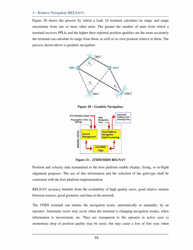
4 – Relative Navigation (RELNAV)
53
Figure 20 shows the process by which a Link 16 terminal calculates its range and range
uncertainty from one or more other units. The greater the number of units from which a
terminal receives PPLIs and the higher their reported position qualities are the more accurately
the terminal can calculate its range from them, as well as its own position relative to them. The
process shown above is geodetic navigation.
Figure 20 – Geodetic Navigation.
Figure 21 – JTIDS/MIDS RELNAV
Position and velocity data transmitted to the host platform enable display, fixing, or in-flight
alignment purposes. The use of this information and the selection of the grid-type shall be
consistent with the host platform implementation.
RELNAV accuracy benefits from the availability of high quality users, good relative motion
between sources, good geometry and time in the network.
The JTIDS terminal can initiate the navigation resets, automatically or manually, by an
operator. Automatic resets may occur when the terminal is changing navigation modes, when
information is inconsistent, etc. They are transparent to the operator in active sync (a
momentary drop of position quality may be seen), but may cause a loss of fine sync when

4 – Relative Navigation (RELNAV)
54
operating passively. Reoccurring automatic resets can indicate that another user is broadcasting
overly optimistic qualities in its PPLI or that problems with own unit navigation processing
exist. Manual resets are needed to correct unusually poor PPLI track correlation or navigation
errors.
As PPLI is permanently exchanged between all platforms, it is important to highlight that air-
air interactions are permanent in RELNAV and transmission delays are always available. The
use of the same principles in the ATM context could drastically increase the potential benefits
that RELNAV can offer well beyond the limited use of air-ground segments for ranging.

5 – Feasibility Assessment and Simulations
55
5 FEASIBILITY ASSESSMENT AND SIMULATIONS
5.1 LDACS1 EXTENSION TO NAVIGATION
In previous chapters the technical characteristics of the DME NAVAID, targeted for
replacement, and those of the potential A-PNT enabler, LDACS1, have been described. As a
potential contribution for synergies, we have also described how military data link technology
supports relative navigation. With all these elements, we are now in position to assess if
LDACS1 can offer the required ranging performance for a certain level of PBN navigation
specifications.
Each 500 kHz-wide LDACS1 OFDM channel can be utilized as a ranging source as ground
stations transmit continuously and synchronously in different frequency bands. The intended
navigation performance shall take advantage of the planned implementation of LDACS1
ground receiver sites (acting as “pseudolites”).
LDACS1 feasibility for A-PNT service was already subject of some initial flight trials,
conducted in November 2012 by the German Aerospace Center (Deutsches Zentrum fur Luft-
und Raumfahrt - DLR) under the auspices of a project designated LDACS-NAV [27]. The
ranging results obtained considered four stations to estimate the aircraft position in 3D and a
clock offset at the single receiver installed onboard a research aircraft (Dassault Falcon 20E).
The hardware components of each ground station included a Rubidium (Rb) atomic clock
reference, a GPS time receiver for off-line station synchronization, an arbitrary waveform
signal generator to generate bandpass versions of an LDACS1 signal and a power amplifier
with appropriate bandpass filters to reduce out-of band emissions. The GPS receiver was
included in the installation set up also to validate the measured range and positioning
information. The range estimates obtained with LDACS1 signals were subject of verification
against GPS-derived data.
The flight trials used the four ground stations mentioned above transmitting an LDACS1 signal
with 10 W transmitting power. The operated channels used the lower part of L-band, between
965-975 MHz.
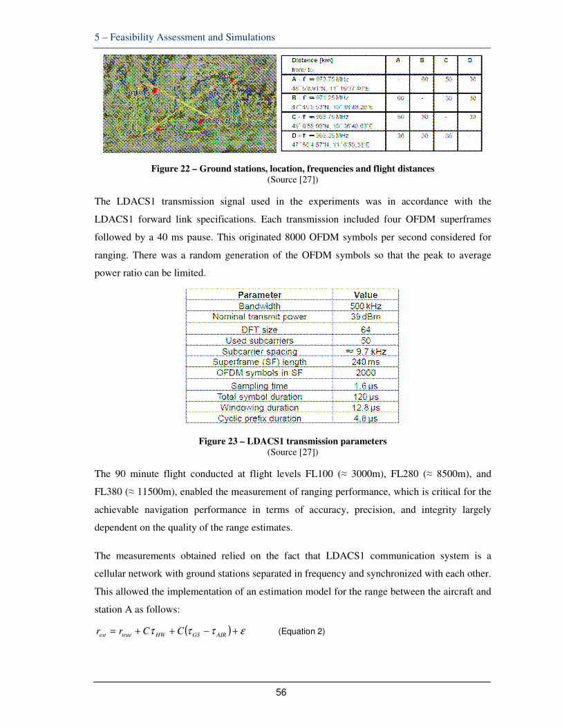
5 – Feasibility Assessment and Simulations
56
Figure 22 – Ground stations, location, frequencies and flight distances
(Source [27])
The LDACS1 transmission signal used in the experiments was in accordance with the
LDACS1 forward link specifications. Each transmission included four OFDM superframes
followed by a 40 ms pause. This originated 8000 OFDM symbols per second considered for
ranging. There was a random generation of the OFDM symbols so that the peak to average
power ratio can be limited.
Figure 23 – LDACS1 transmission parameters
(Source [27])
The 90 minute flight conducted at flight levels FL100 (≈ 3000m), FL280 (≈ 8500m), and
FL380 (≈ 11500m), enabled the measurement of ranging performance, which is critical for the
achievable navigation performance in terms of accuracy, precision, and integrity largely
dependent on the quality of the range estimates.
The measurements obtained relied on the fact that LDACS1 communication system is a
cellular network with ground stations separated in frequency and synchronized with each other.
This allowed the implementation of an estimation model for the range between the aircraft and
station A as follows:
( ) ετττ +−++= AIRGSHWtrueest CCrr (Equation 2)

5 – Feasibility Assessment and Simulations
57
where estr is the estimated range, truer is the actual (unknown) range, c is the speed of light,
HWτ is the delay due to the hardware components in transmitter and receiver, AIRGS ττ − is the
clock offset between ground station and the airborne system and ε is a perturbation that
accounts for all other errors, such as multipath propagation, tropospheric delays, and white
random noise.
Figure 24 – LDACS1 is a cellular configuration
Any delays due to transmitter and receiver hardware of the measurement system were subject
of compensation through an accurate calibration of the measurement equipment. Station A
calibration allowed to estimate the transfer function of the whole transmission path including
the LDACS1 transmission signal. The resulting calibration signal considers the impact of both
the corresponding transmitter and receiver hardware effects and it is recorded when the clocks
of both stations are manually aligned in terms of frequency and phase.
The baseband of the calibration signal ( )θjeC is given by:
( ) ( ) ( ) ( )θθθθ jjjjeSeTeReC ..= (Equation 3)
where ( )θjeS is the baseband frequency domain representation of the transmitted LDACS1
signal, and T ( )θje and R ( )θj
e are the baseband frequency responses of the transmitter and
receiver hardware.
The actual received signal Y ( )θje can be represented as:
( ) ( ) ( ) ( )θθθθ jjjjeEeHeCeY ..= (Equation 4)

5 – Feasibility Assessment and Simulations
58
where ( )θjeH is the baseband frequency that accounts for all other signal delays and E ( )θj
e is
the additive measurement noise.
In order to estimate the range the measured received signal Y ( )θje was multiplied with a
complex conjugated and normalized version of the calibration signal:
( ) ( ) ( )2^
/* θθθ jjjeCeCeC = (Equation 5)
In other words, the signal Y ( )θje was subject of correlation with the calibration signal.
The estimated amplitude and phase responses for the calibration signal were pre-defined; as
well as the clock offset between Station A and the receiver clock.
Assuming that the propagation channel between transmitter and receiver consists purely of a
single propagation path (line of sight), the range estimation can be solved by multiplying the
received signal Y ( )θje with the normalized, complex-conjugate calibration signal ( )θj
eC^
.
The pseudo range could be estimated, either from the phase of the product ( )θjeC
^
xY ( )θje or
by estimating the location of the maximum of its inverse Fourier transform, i.e. finding the
location of the maximum correlation peak.
The range estimation results obtained, using the abovementioned correlation principles, for
different segments of the flight were the following:

5 – Feasibility Assessment and Simulations
59
Figure 25 – Estimated ranges and range errors computed for the selected flight segments
(Source [27])
Figure 25 shows the estimated ranges and range errors computed for the selected flight
segments for (a,d) FL100, (b,e) FL280, and (c,f) FL380. Graphs (a), (b), and (c) show the
estimated range and the range determined from ground truth over time. Graphs (d), (e) and (f)
show empirical range error distributions.
The conclusion was that for lower altitudes the range estimation is far worse than for higher
altitudes. However, a non-line of sight (non-LOS) case was observed at FL100, resulting in a
range error of more than 2000 m. The Root Mean Squared Error (RMSE) for the whole flight
is only 15.2 m, with 99 percentile corresponding to only 50 m. The bias of the range estimation
is only 6.7 m. Feasibility could not be demonstrated for flight level 100 (10.000 feet). The
encountered problems indicate that, for lower flight levels, non-LOS transmissions in a
propagation environment with obstacles (Rayleigh) evidence poor ranging accuracies.
In multipath rich environments ranging becomes a challenging problem when used with low
bandwidth signals: unless multipath interference is resolved, large ranging errors are typical.
At this stage it is fundamental to recall, from Section 2, that the feasibility target would be

5 – Feasibility Assessment and Simulations
60
RNP-0.3 implying a lateral accuracy limit of 556.6 m. Due to the above described results for
FL100 or below even for this requirement the ranging accuracy could not be demonstrated.
This behaviour might have a bearing on various factors affecting the performance of the range
estimator for lower elevation angles namely:
- tropospheric effect that might lead to a higher estimation bias;
- relative position difference between the GPS antenna, which is mounted on the
top of the aircraft fuselage, and the LDACS1 receiving antenna, which is located
on the bottom (since the antennas are not collocated, the ground truth determined
from GPS data depends on the exact roll, pitch and yaw of the airplane);
- interference due to the spectral proximity of the LDACS1 signals to DME;
- multipath effects, which will be considered later in the thesis, significantly
impacting the instability of the range estimates at lower altitudes, especially
during banking turns.
Figure 26 – Range error distribution for the entire flight (higher flight levels) (Source [27])
A key aspect was that the LDACS prototype used by DLR, described in [27], was still rather
embryonic and does not evidence full compliance to all LDACS specifications including
advanced channel estimation allowing severe multipath to occur. The tested prototype features
only a form of Reed-Solomon (RS) coding and pilot insertion.
Subsequent theoretical work was conducted by DLR addressing the effect of multipath on
LDACS1. This work considered a state-of-the-art super-resolution multipath estimation
algorithm. That algorithm is based on the so-called “fast variational sparse Bayesian parameter
estimation scheme” and a classical Kalman filter and was used for tracking individual
multipath components [39] [40].

5 – Feasibility Assessment and Simulations
61
That algorithm would allow the incremental estimation of the parameters of multipath
components, which are the delay and Doppler frequency of each propagation path, as well as
automatic estimation of number of components detectable in measurement data. Using Kalman
filter the individual propagation paths can be tracked over time.
This tracking algorithm was named Sparse Adaptive Multipath Estimation (SAME) and
enabled to follow the GPS range quite closely, mitigating the multipath interference and
drastically reducing the range root mean square error (RMSE).
It was decided not to cover that analysis in the present thesis due to its complexity.
Nevertheless, it was noted from [39] that one sample equals the distance of about 480m,
considering the speed of light in air. LDACS1 symbol consumes 120 µs and one sample takes
1.6 µs. With that it would be possible to associate the range error in terms of distance with the
performance in terms of bit (or symbol) error rate (BER).
Instead of the SAME approach, this thesis relies on the statements in the LDACS1
specification [22] where it is prescribed that a target Bit Error Rate (BER) of 10-6 must be
achieved. This specification says that a BER at that level fulfills the optimal operation of
LDACS1 assuming the maximum frequency offset, for the transmission between the GS and
the AS as well as maximum AS Doppler shift, relative to the GS, corresponding to the aircraft
speed of ± 850 knots16.
In summary, three LDACS1 improvements will be proposed. One of those will focus on
mitigating the effects of multipath/Doppler shift. For that case it is assumed that a BER at 10-6,
achieved with improved channel estimation, will guarantee LDACS1 optimal performance
including a ranging error far below the required 556.6 meters required for RNP-0.3. This is an
important assumption for this work.
This thesis will propose three specific LDACS ranging/position determination improvements
based on the military data link example:
• use of Kalman filter to improve position tracking
• multilateration on the basis of air-air transmissions
16 This assumption is valid when GS is using all FL sub-carriers (Nused = Nu) with QPSK modulation, convolutional coding with rcc = ½, interleaving over 8 FL data frames and Reed-Solomon RS (101,91,5) coding in FL data frames, the airborne LDACS1 RX shall fulfil the reference BER requirement (10-6 from the specification) when operating at the sensitivity level S0 ≤ -104.13 dBm.

5 – Feasibility Assessment and Simulations
62
• a more advanced channel estimation approach.
5.2 USE OF KALMAN FILTER TO IMPROVE POSITION TRACKING
What is a Kalman Filter?
A Kalman filter is an optimal estimator - it infers parameters of interest from indirect,
inaccurate and uncertain observations. It is recursive so that new measurements are processed
as they arrive. Kalman filtering is used to track the estimated signals after using an algorithm to
detect and estimate the individual multipath components. A more extensive description of the
features and use of Kalman filters can be found in annex B.
The estimation algorithm offers an incremental estimation of the parameters of the multipath
components, namely the delay and Doppler frequency of each propagation path, as well as
automatic estimation of the number of components, which can be detected in measurement
data.
When applied for the tracking of moving target in space [28], Kalman filter became a standard
estimation algorithm extensively used in the development tracking algorithms. Kalman filter
would provide minimum mean square error (MMSE) when the measurements are in Cartesian
coordinates, measurements are independent & gaussian distribution and target behaviour (i.e.
target mathematical model) is known.
The goal of the target tracking system is to form and maintain track on target of interest from
the measurements provided by the sensors. Figure 27 shows the information flow diagram of a
typical recursive target tracking system. Its basic elements are time prediction and
measurement update. First step is to carry out time prediction. Prediction of tracks from the
frame uses the target process model. In measurement update, the measurement from frame is
incorporated into the predicted state estimate to obtain an improved estimate using
measurement model.

5 – Feasibility Assessment and Simulations
63
Figure 27 – Information flow diagram of recursive target state estimation
Annex B contains details on the particular model and algorithm implemented by the Kalman
filter when used for target state estimation. In conclusion, the aim of the Kalman filter is to
combine the measurements taken from the target with the information provided by the motion
model in order to obtain an optimal estimate of the target state. Its application as in the case of
military relative navigation allows a drastic reduction of the ranging error MMSE.
Simulation
A SIMULINK model ascertains the level of improvement offered when a Kalman filter is
associated with LDACS. This model (see Figure 28) generates aircraft position, velocity, and
acceleration in polar (range-bearing) coordinates; it adds measurement noise to simulate
inaccurate readings by the sensor and uses a Kalman filter to estimate an aircraft's position and
velocity from noisy radar measurements.
Figure 28 – SIMULINK model
Running the model we obtain
- The actual trajectory compared to the estimated trajectory
- The estimated residual for range

5 – Feasibility Assessment and Simulations
64
- The actual, measured, and estimated positions in X (North-South) and Y (East-
West)
Estimation of the aircraft's position and velocity results from the 'Radar Kalman Filter'
subsystem. This subsystem samples the noisy measurements, converts them to rectangular
coordinates, and sends them as input to the Kalman Filter block.
The Kalman Filter block produces two outputs in this application. The first is an estimate of the
actual position. This output suffers conversion back to polar coordinates so that it can compare
with the measurement to produce a residual: the difference between the estimate and the
measurement. Kalman Filter smoothes the resulting position data to produce the estimate of the
actual position.
Figure 29 shows that the initial range error reduces by the action of the Kalman filter after
taking more samples. It goes easily from around 5000 feet to less than 20 feet after 100
measurements. Similarly, it is visible that the position estimated as an output from the Kalman
filter becomes very close to the real position.
Higher-precision measurements could result from the correct setting of parameters/initial
values like Initial Velocity Mismatch and Measurement Noise.

5 – Feasibility Assessment and Simulations
65
Figure 29 – Simulation results
Kalman filter could add to LDACS configuration, as shown for the military Relative
Navigation data link solution described before (see Figure 21).
5.3 MULTILATERATION ON THE BASIS OF AIR-AIR TRANSMISSIONS
LDACS1 System Specification defines an air-air mode to be part of LDACS design. This mode
supports direct A/A communications without ground support. The LDACS system shall offer a
broadcast A/A surveillance link and an addressed (point-to-point) A/A data link, both with
direct air-air connectivity. A/A communications between involved LDACS airborne stations
takes place in a decentralized, self-organised way without any need for ground support.
The same specification foresees that LDACS A/A mode uses an OFDM-based PHY layer with
different parameters (e.g. sub-carrier spacing) than those specified for air-ground mode. An
OFDM based PHY layer is combined with the TDMA based users’ access to the shared
broadcast channel.
The usage of TDMA, high number of potential users and propagation guard times mandate the
usage of A/A data frames that are relatively short compared with frames in the A/G mode. The
selected data frame size and OFDM symbol duration lead to the required RF channel
bandwidth that is higher than for the A/G mode.
A flexible LDACS A/A protocol has been designed to support the aircraft population within
the operational range defined by the physical layer design.
Most A/A transmissions are broadcast as explained before. The LDACS specification
envisages also the periodic transmission of management data used to overcome the hidden
station problem: simultaneous transmission of two or more nodes which are not directly within
each others transmission range, but are both within the transmission range of the victim
receiver.
A potential way to improve the ranging performance of LDACS could be to take advantage of
air-air broadcast transmissions to share positioning information amongst all platforms. This
solution would be similar to the military data link relative navigation functionality described in
chapter 4 above.
As for the case of military RELNAV, recurrent exchange of positioning and identification
messages (PPLI) could benefit from LDACS A/A mode and support improved position

5 – Feasibility Assessment and Simulations
66
determination. The broadcast nature, the use of TDMA and the periodic transmissions already
envisaged for LDACS A/A could facilitate the implementation of PPLI-alike exchanges.
It is important to recall that for military RELNAV each airborne terminal continuously
calculates its own position by measuring the Time of Arrival of all received PPLIs messages.
This function is often designated “multilateration”. As such, RELNAV allows the terminal to
calculate an accurate value for the range between itself and another transmitting unit. This very
accurate range measurement is possible because of the precise timing the terminal must
maintain after achieving synchronisation with the network.
Multilateration of signals Time Difference of Arrival (TDOA) of signals at different receivers
to identify the position of the source is a technique that military have already used for several
decades. Recently, this technique has become available to civil organisations and, for some
years, used in airport surveillance. Nowadays, these same techniques are in operation for larger
areas such as En-Route or Approach areas. Those are the so-called Wide Area Multilateration
(WAM) systems.
Figure 30 – Multilateration principle (Source EUROCONTROL)
Multilateration is all about position-determination on the basis of a set of hyperboloids defined
after the “triangulation” of signals exchanged between some referenced transceivers
(designated as “pseudolites”). For the case of air-air multilateration, the different airborne
stations act as those pseudolites.

5 – Feasibility Assessment and Simulations
67
The set of equations supporting multilateration is depicted in figure 31 below.
Figure 31 – Multilateration Equations
If such LDACS A/A multilateration improvement would be implemented the performance
gains could be similar to those offered by PPLIs exchanges in military RELNAV: terminal´s
position accuracy with a value for position quality (Qp) indicating that its position uncertainty
is up to 50 feet. This calculated value for Qp would then be shared in PPLI messages
supporting estimation of a different value based on different TOAs and Qp values from the
other network units.
LDACS exists only as prototype and industrial research is still underway before a final
specification is frozen. Consequently, there is still time to integrate air-air relative navigation in
the final system design. The ability for each aircraft to derive its position based on air–air
communications with other aircraft in the vicinity, together with the sharing of PPLI messages
containing position data, would significantly contribute to overcome the limitations observed
in the performance of LDACS air-ground ranging.
5.4 A MORE ADVANCED CHANNEL ESTIMATION APPROACH
Multipath in OFDM Systems
It is important to recall here the assumption made before: LDACS1 improvements target a
better ranging performance, mitigating multipath/Doppler shift, but it is assumed that a BER at
10-6, achieved with improved channel estimation, will guarantee LDACS1 optimal
performance including a ranging error far below the required 556.6 meters required for RNP-
0.3.
As stated before, the original LDACS1 specification requires a Bit Error Rate (BER) of 10-6, or
better, after Forward Error Correction. Looking at the results of the DLR trials, it seems likely
that this specification feature was not respected by the embryonic LDACS prototype used in
those trials. In this section we will perform a simulation to verify the behavior of LDACS
( )
( )
( )
delays hyperbolic =
,...),,(1
,...),,(1
,...),,(1
,, QRL
Q
R
L
zyxhOCQCOQc
zyxgOCRCORc
zyxfOCLCOLc
τ
τ
τ
τ
=−+⋅=
=−+⋅=
=−+⋅= (Equation 6)
(Equation 7)
(Equation 8)
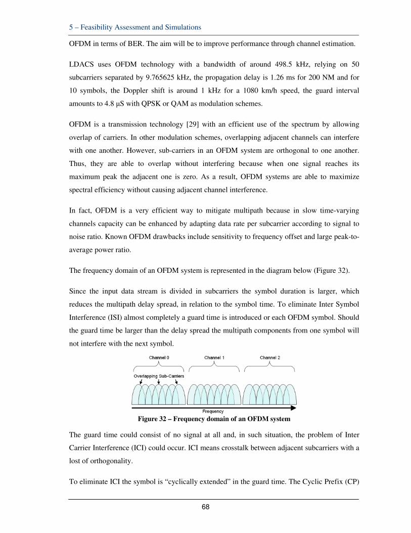
5 – Feasibility Assessment and Simulations
68
OFDM in terms of BER. The aim will be to improve performance through channel estimation.
LDACS uses OFDM technology with a bandwidth of around 498.5 kHz, relying on 50
subcarriers separated by 9.765625 kHz, the propagation delay is 1.26 ms for 200 NM and for
10 symbols, the Doppler shift is around 1 kHz for a 1080 km/h speed, the guard interval
amounts to 4.8 µS with QPSK or QAM as modulation schemes.
OFDM is a transmission technology [29] with an efficient use of the spectrum by allowing
overlap of carriers. In other modulation schemes, overlapping adjacent channels can interfere
with one another. However, sub-carriers in an OFDM system are orthogonal to one another.
Thus, they are able to overlap without interfering because when one signal reaches its
maximum peak the adjacent one is zero. As a result, OFDM systems are able to maximize
spectral efficiency without causing adjacent channel interference.
In fact, OFDM is a very efficient way to mitigate multipath because in slow time-varying
channels capacity can be enhanced by adapting data rate per subcarrier according to signal to
noise ratio. Known OFDM drawbacks include sensitivity to frequency offset and large peak-to-
average power ratio.
The frequency domain of an OFDM system is represented in the diagram below (Figure 32).
Since the input data stream is divided in subcarriers the symbol duration is larger, which
reduces the multipath delay spread, in relation to the symbol time. To eliminate Inter Symbol
Interference (ISI) almost completely a guard time is introduced or each OFDM symbol. Should
the guard time be larger than the delay spread the multipath components from one symbol will
not interfere with the next symbol.
Figure 32 – Frequency domain of an OFDM system
The guard time could consist of no signal at all and, in such situation, the problem of Inter
Carrier Interference (ICI) could occur. ICI means crosstalk between adjacent subcarriers with a
lost of orthogonality.
To eliminate ICI the symbol is “cyclically extended” in the guard time. The Cyclic Prefix (CP)

5 – Feasibility Assessment and Simulations
69
[30] (see Figure 33) ensures that the multipath signals with delays smaller than the guard time
cannot cause ICI. This is done by ensuring that any delayed replicas of the OFDM symbol have
an integer number of cycles within the FFT interval, assuming that the delay is smaller than the
guard time.
Figure 33 – Cyclic prefix insertion
In summary, in a typical OFDM broadband wireless communication system, a guard interval,
using cyclic prefix, shall be inserted to avoid ISI and ICI [31] [32] [33].
This guard interval is required to be at least equal to, or longer than the maximum channel
delay spread. This method is very simple, but it reduces the transmission efficiency. Some
authors defend that transmission efficiency can be increased through a time domain equalizer
to shorten the channel impulse response within the guard interval.
In a channel affected by multipath propagation, the signal interacts with many objects in the
environment producing multiple copies of the transmitted signal i.e. multipath signal
components. These multipath signals might be attenuated in power, shifted in phase and/or
frequency and delayed in time. For this reason when they are all combined at the receiver side,
the reconstructed signal is distorted. Indeed, if a single narrow pulse is transmitted the received
signal is a pulse train and each component corresponds to a different path. Moreover, In
OFDM systems, due to user mobility, each carrier is subject to Doppler shifts resulting in time-
varying fading.
This leads to the discussion about the need to ensure coherent detection. OFDM demodulation
must be synchronized with the start and end of the transmitted symbol (or bit) period and
knowledge is needed about the reference phase and amplitude of the constellation of each
subcarrier (affected by random phase shift or and amplitude change due to carrier frequency
offset). Coherent detection is the way to cope with such phase and amplitude variations using
one of the channel estimation techniques.

5 – Feasibility Assessment and Simulations
70
Channel estimation models/algorithms shall not create too much training overhead and aim at
detecting the reference values that allow the best decision boundaries for the constellation. The
channel estimation block of an OFDM receiver determines the reference phase and amplitude
for all subcarriers. Out of the multiple channel estimation techniques we decided to choose, for
the present work, one based on the use of Kalman filter.
It is a decision-directed channel estimation option that avoids the use of pilots that have a cost
in terms of transmitted power. In this case, data estimations are used to remove the data
modulation from the received subcarriers after which all subcarriers can be better used to
estimate the channel.
Use of Kalman Filter
We have concluded from the DLR trials described before that multipath propagation might be
a major factor disturbing the ranging performance at lower flight levels. Mitigating such
multipath effects entails the application of:
- a multipath estimation algorithm
- a Kalman filter (as one of the options for channel estimation)
- improved positioning taking advantage of air-air multilateration or other sources
As explained before, time varying frequency selective multipath channels destroy the
orthogonality of OFDM subcarrier introducing inter carrier interference. In this thesis we will
focus on the use of Kalman filtering to support channel estimation thus mitigating inter carrier
interference, caused by multipath effects, in OFDM technology, which is the basis of LDACS.
A time domain Kalman filter can be used [34] to estimate channel impulse response on every
sample of OFDM symbol. The estimated coefficients are applied to the equalizer17 to equalize
received OFDM signal.
Training sequence/pilot aided techniques and blind techniques are two basic families for
channel estimation. In our case we consider the use of a Kalman filter to perform time-based
channel estimation (based on the concept of Minimum Mean Square Error) [35] [36]. In the
case of relative navigation implemented in military data links, described before, Kalman filters
are used for a different purpose: they can also help to correct trajectories of moving objects.
Figure 34 below depicts a full OFDM transceiver scheme with the channel estimation /
17 Minimum mean-square error (MMSE) approach which minimizes the sum of ISI and noise.

5 – Feasibility Assessment and Simulations
71
equalization ensured by the use of Kalman filtering. The OFDM symbols are obtained on the
basis of QPSK or QAM modulation followed by the application of Indirect/Direct (Fast)
Fourier Transforms, insertion (or not) of cyclic prefix/guard band (and eventually pilot/training
symbols), a noisy channel with Rayleigh multipath fading and a number of series/parallel
conversions and coding.
Figure 34 – OFDM scheme 1 with Kalman filter applied
The joint problem of channel estimation and ICI suppression in high mobility OFDM systems
can be addressed through the application of a Kalman filter followed by the use of
convolutional coding. This method is seen to provide a good performance at high Doppler
spreads.
Simulation Results
As stated in the introduction, when the scope was defined, this is not a thesis on OFDM.
However, a SIMULINK model (Annex C) was used to evaluate the standard OFDM Bit Error
Rate (BER), without channel estimation, based on the parameters applicable to LDACS as
recalled before.
Initially we could see some multipath components (Figure 35).
Figure 35 – Multipath fading components

5 – Feasibility Assessment and Simulations
72
Subsequently, a MATLAB script for time varying channel estimation using Kalman filter
(Annex C) was used to identify the level of improvement introduced by channel estimation, for
equivalent parameters, which is fundamental to remove ISI/ICI and achieve the required level
of synchronization mitigating multipath.
We confirm in this simulation the effect of applying Kalman filtering to channel estimation as
described in [38] Fundamentals of Statistical Signal Processing, Volume I: Estimation Theory
(v. 1), Steven M. Kay. A Mean Square Error (MSE) of more than 0.2 when estimation is not
applied decreases to around 0.02 after 100 samples as soon as Kalman filters are used (see
Figures 36 and 37).
After going through several published references (see reference list [34] to [36]) on OFDM
channel estimation using Kalman filters, it can be concluded that the order of magnitude of
such channel estimation mitigating benefit is always above 10 times and it offers benefits
above all other channel estimation techniques.
The channel was defined to include Rayleigh fading, SNR=20 dB, the tolerated Doppler shift
was set to 1000 Hz (as for LDACS) and the Doppler spectrum type was Jakes. QPSK
constellation was defined with M=4 and a sample rate of Ts=128 µS.
Even if those simulations were very basic, it could be concluded that for a LDACS OFDM
channel using QPSK modulation, with a Signal Noise Rate (SNR) until 15 to 20 dB, we obtain
a BER between 10-2 and 10-3 when no channel equalization is used. With channel estimation,
the BER moves to the area around 10-4 to 10-6. For other modulation schemes the results are
similar (see Figures 38 and 39 for QAM standard - without channel estimation – and with
Kalman).
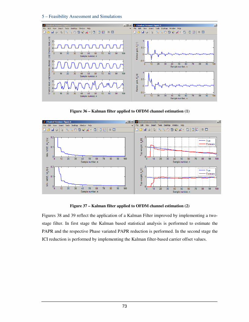
5 – Feasibility Assessment and Simulations
73
Figure 36 – Kalman filter applied to OFDM channel estimation (1)
Figure 37 – Kalman filter applied to OFDM channel estimation (2)
Figures 38 and 39 reflect the application of a Kalman Filter improved by implementing a two-
stage filter. In first stage the Kalman based statistical analysis is performed to estimate the
PAPR and the respective Phase variated PAPR reduction is performed. In the second stage the
ICI reduction is performed by implementing the Kalman filter-based carrier offset values.

5 – Feasibility Assessment and Simulations
74
Figure 38 – Comparison of SNR vs BER of different QAM OFDM systems (Source http://www.ijritcc.org )
Figure 39 – Comparison of SNR vs BER of different QAM OFDM systems
(Source http://www.ijritcc.org )
The interference leads (Figure 39) to a poor signal to noise ratio as well as high bit error rate.
The proposed system will improve the signal by removing the different kind of impurities over
the signal. These impurities include the ICI, PAPR and the noise over the signal. The signal
will be more effective than any standard OFDM.
A Mean Square Error of more than 0.2 when channel estimation is not applied decreases to

5 – Feasibility Assessment and Simulations
75
around 0.02 after 100 samples as soon as Kalman filters are used. As said before, it becomes
clear that channel estimation using Kalman filters enables a 10-time enhancement and it offers
benefits above all other channel estimation techniques. With that approach the specification
BER value of 10-6 can be eventually within reach.
Again, this LDACS improvement seems suitable for a future final specification to mitigate
decisively the inconvenient generated by higher multipath levels.

6 – Conclusions
76
6 CONCLUSIONS
6.1 SUMMARY OF RESULTS
Future aeronautical navigation requirements will rely mainly on GNSS satellite infrastructure
and its augmentation systems. However, GNSS vulnerabilities including jamming, solar events
or other outages dictate the need to keep a ground based back up to guarantee the service
continuity. Current navigation infrastructure rationalisation plans indicate that existing
Distance Measuring Equipment will be in operation to ensure the aforementioned navigation
back up to GNSS.
Existing European DME infrastructure evidences significant coverage limitations in particular
at lower flight levels. In addition, DMEs are “paired” with other NAVAIDS (VOR, ILS, etc.)
and its integrity levels might be insufficient to fulfil the requirements of advanced navigation
concepts, namely the more demanding specifications defined under the framework of ICAO
Performance Based Navigation.
The main PBN specifications planned for the European airspace include various levels of
RNAV or RNP. DME/DME positioning may not support RNP-0.3 navigation specifications
that require on-board performance monitoring and failure alerting. The high level goal of
OPMA is to achieve a bound on Total System Error at a 10-5 per flight hour integrity risk level.
Integrity target would be to sustain defined levels of RNP (e.g 0.3 NM = 556.6 meters),
including OPMA.
To overcome the limitations of existing DME infrastructure to be seen as an effective GNSS
back up and to alleviate the spectrum congestion in the band 960 to 1200 MHz research is
ongoing to identify a means of Alternative Positioning Navigation and Timing. The
reutilization of future air-ground data links (e.g LDACS) is seen as one of the most promising
options.
LDACS will be implemented anyway as an evolution of today´s air-ground data links (e.g
VDL Mode 2), used to support controller-pilot data link communications, as well as to enable
advanced aeronautical communications requirements. LDACS rely on OFDM technology. To
verify its suitability to be used concomitantly as A-PNT an LDACS prototype was submitted to
flight trials conducted under the aegis of DLR (the German Aerospace Center).

6 – Conclusions
77
Those trials concluded that, for lower altitudes, the range performance is quite bad as a non-
line of sight (NLOS) case was observed at FL100 (10.000 feet), which resulted in a range error
of more than 2000 meters. Performances at higher altitudes were satisfactory: the Root Mean
Squared Error for the whole flight was 15.2 m, with 99 percentile corresponding to 50 m. The
bias of the range estimation is only 6.7 m. In a propagation environment with obstacles
(Rayleigh) and for lower flight levels, LDACS NLOS transmissions evidence poor ranging
accuracies. DLR did progress some follow up work to mitigate multipath through advanced
Bayesian algorithms but that work was not yet conclusive and was not pursued in this thesis.
For LDACS to be considered as a feasible system for A-PNT it is imperative to identify areas
for improvement so that the ranging/positioning accuracy satisfies the identified targets for
PBN.
In the military context, a TDMA air-ground data link (JTIDS/MIDS Link 16) is operational for
relative navigation. RELNAV is an automatic function of the Link 16 terminal, used to
determine the distance between platforms by measuring the arrival times of transmissions and
correlating them with reported positions.
RELNAV data improves unit's positional accuracy. If two or more units have accurate and
independent knowledge of their geodetic positions, RELNAV can provide all units of the
network with accurate geodetic positions. As a result, the precise geodetic position of every
unit can be permanently available at every other unit.
Each airborne terminal continuously calculates its own position by measuring the Times of
Arrival of all received Precise Participant Location Information messages. As such, RELNAV
allows the terminal to calculate an accurate value for the range between itself and another Link
16 transmitting unit. This very accurate range measurement is possible because of the precise
timing the terminal must maintain after achieving synchronisation with the network.
Military RELNAV strongly relies on the air-air communications capability of Link 16,
allowing the exchange of the recurrent PPLI messages, and on the use of a Kalman filter to
compute position and velocity solutions in two separate grids, the relative grid (REL GRID -
u,v,w) and the geodetic grid (GEO GRID - latitude, longitude, altitude).
Receiving PPLIs from additional units further contributes to the terminal´s position accuracy.
The value for Position Quality (Qp) can range from 0 (indicating that its position uncertainty is
greater than 18.080 feet) to 15 (indicating that its position uncertainty is within 50 feet). The
6 – Conclusions
78
terminal will then transmit this calculated value for Qp in its own PPLI – until it calculates a
different value based on different TOAs and Qp values from the other network units from
which it receives messages.
The ranging/positioning improvements proposed for LDACS include the two main features
used in military RELNAV: exchange of recurrent PPLI messages and TOA estimation based
on air-air exchanges and the use of a Kalman filter for position estimation. On top of that, an
approach based on the use of advanced channel estimation is proposed to mitigate the harmful
effect of OFDM multipath propagation and resulting inter carrier interference.
The first improvement would be implemented taking advantage of LDACS A/A broadcast
transmissions. As the LDACS specification envisages already the periodic transmission of
management data, it can be assumed that the recurrent exchange of PPLI messages and TDOA
estimation could be implemented offering a range performance improved up to the indication
of position uncertainty is within 50 feet.
The second improvement, the use of a Kalman filter for position estimation, had the objective
to improve the ability to track a moving target in space. Kalman filter will provide minimum
mean square error when the measurements are in Cartesian coordinates.
A simulation using a SIMULINK model estimated the aircraft's position and velocity, derived
from a Kalman Filter subsystem. The result was a reduction of the initial range error by the
action of the Kalman filter in the sequence of a number of samples taken. That range error
decreased from around 5000 feet to less than 20 feet after 100 measurement samples. End
conclusion was that the position estimated as an output from the Kalman filter becomes very
close to the real position.
Finally, an improvement to the OFDM configuration selected for LDACS was analysed also
using SIMULINK and MATLAB model/script. The objective was to mitigate multipath
problems and improve BER performance through the use of Kalman filter to perform channel
estimation.
This improvement relies in an important assumption which is that a BER at 10-6, achieved with
improved channel estimation, will guarantee LDACS1 optimal performance including a
ranging error far below the required 556.6 meters required for RNP-0.3 mitigating
multipath/Doppler shift.
The basic simulations performed gave the indication that an LDACS OFDM channel using

6 – Conclusions
79
QPSK modulation with a SNR until 20 dB triggers a BER between 10-2 and 10-3 when no
channel equalization is used. These are really bad BER results. With channel estimation, the
BER moves to the area around 10-4 to 10-6. For other modulation schemes the results are
similar.
A Minimum Mean Square Error (MMSE) of more than 0.2 when channel estimation is not
applied decreases to around 0.02 after 100 samples as soon as Kalman filters are used. This
shows that the order of magnitude of such channel estimation using Kalman filters is always
above 10 times. With that approach, the LDACS specification BER value of 10-6 could
eventually be within reach.
It was clear that the LDACS prototype used in DLR trials did not meet the 10-6 BER level and
that improvements are necessary. Channel estimation based on Kalman filters could provide
such level of enhancement and mitigate decisively the inconvenient generated by higher
multipath levels, Doppler effects and ICI.
6.2 IMPACT ON NAVIGATION INFRASTRUCTURE RATIONALIZATION
The abovementioned improvements can still be incorporated in future LDACS specifications.
LDACS as a future aeronautical communications data link is still being subject of industry
research efforts in the context of ICAO and in SESAR industry research projects in Europe. No
final aviation standard is in place yet at the level of EUROCAE, RTCA or ICAO. With the
proposed improvements, LDACS would be an optimal candidate for A-PNT supporting PBN
navigation requirements up to the level of RNP 0.3.
The introduction of a feasible A-PNT system, compliant with PBN requirements, will be
fundamental to enable advanced navigation specifications that rely on satellite based (and
augmentations) signals together with the availability of a reversionary back up to mitigate
GNSS outages. That A-PNT alternative will satisfy RNP requirements including appropriate
ranging performance, integrity and alerting in accordance with the needs of the navigation
specifications for the European airspace.
The proposed A-PNT alternative will take advantage of a data link infrastructure, already
planned, to fulfil air-ground communications requirements. Consequently, at least the airborne
equipage will be available and only the ground service provision needs still to be deployed.
Those communications requirements comprise CPDLC and Trajectory Management

6 – Conclusions
80
applications that can co-exist with the proposed navigation functions. In parallel, the use of
LDACS as A-PNT will allow the gradual decommissioning of multiple DMEs with the
spectrum and economic gains associated.
A 2006 study on the Fragmentation of European ATM conducted by the EUROCONTROL
[37] indicated that the cost of duplicated and non-rationalised Communications Navigation and
Surveillance (CNS) infrastructure represents something around 20% to 30% of annual cost.
This represents an amount between 900 to 1.400 million euros/year but these figures referred to
2006 and did never see any update.
The same study identifies the costs that can be attached to the navigation infrastructure that are
rather low (10% of the total) when considering surveillance (radars) and ATC center systems.
Nevertheless, the author believes that the direct savings of rationalizing the DME
infrastructure, at current prices, will involve several hundreds of million euros/year with a
much higher amount associated to economies of scale and indirect impact on a more seamless
infrastructure (e.g. avionics) and reduced controller workload.
6.3 SYNERGIES / WAY AHEAD
The present proposals could be relevant in the context of ongoing SESAR research projects,
sponsored by the European Commission, where DLR and other industry partners are relevant
contributors.
The EUROCONTROL organization, where the author of this thesis has his present assignment,
is also a relevant SESAR partner. Nevertheless, the development of this text pursued only
academic purposes, on an individual basis and without any link with his EUROCONTROL
duties.
In any case, there are significant ongoing discussions about A-PNT and the vulnerabilities
associated with the use of GNSS and introduction of PBN in several ICAO groups, panels and
other working groups where all options can have a progress towards defragmentation of
aviation infrastructure with safety and economic gains.

References
81
REFERENCES
[1] Commission Regulation (EC) No 29/2009 of 16 January 2009 laying down
requirements for Data Link Services.
[2] Communications Operating Concept and Requirements for the Future Radio System,
COCR Version 2.0, EUROCONTROL/FAA Future Communications Study
Operational Concepts and Requirements Team, May 2007.
[3] Annex 10 to the Convention on International Civil Aviation Volume I Radio
Navigation Aids, International Civil Aviation Organization, Sixth Edition July 2006.
[4] Strategic Guidance on Evolution of Conventional Navigation Aids, Working Paper,
Navigation Sub Group, EUROCONTROL, 2013.
[5] Current and Planned Global and Regional Navigation Satellite Systems and Satellite-
based Augmentations Systems, International Committee on GNSS Providers’ Forum,
United Nations Office for Outer Space Affairs, New York, 2010.
[6] EUROCONTROL Standard Document for Area Navigation Equipment - Operational
Requirements and Functional Requirements, Edition 2.2 – December 1998.
[7] Minimum Aviation System Performance Standards for Required Navigation
Performance for Area Navigation, document RTCA DO-236A /EUROCAE ED75,
1998.
[8] ICAO Document 9613 (PBN Manual), Third Edition, 2008.
[9] European Airspace Concept Handbook for PBN Implementation, Edition 3.0,
EUROCONTROL, June 2013.
[10] Global Navigation Space Systems: Reliance and Vulnerabilities, The Royal Academy
of Engineering, March 2011 (www.raeng.org.uk).
[11] A-RNP reversion in case of GPS Loss Safety Desk Study Report, EUROCONTROL,
28 August 2013.
[12] Navigation Strategy, Edition 2, EUROCONTROL, April 2014.
[13] Annex 10 to the Convention on International Civil Aviation Volume V Aeronautical
Radio Frequency Spectrum Utilization, International Civil Aviation Organization,
Third Edition, July 2013.

References
82
[14] Joachim Wollweber, Distance-Measuring-Equipment Compendium - Antennas and
Systems in the Band 960 to 1215 MHz, Version 0.97, 2009.
[15] Annex 10 to the Convention on International Civil Aviation Volume III
Communication Systems (Part I Digital Data Communication Systems, Part II Voice
Communication Systems), ICAO, 2nd Edition, July 2007.
[16] ICAO Aeronautical Telecommunication Network (ATN), Manual for the ATN using
IPS Standards and Protocols (Doc 9896), Second Edition, September 2011.
[17] An Introduction to LTE, 3GPP LTE Encyclopaedia, December 2010.
[18] IEEE Approves IEEE 802.16m – Advanced Mobile Broadband Wireless Standard,
News release (IEEE Standards Association), 31 March 2011.
[19] FCI Technology Investigations: L band Compatibility Criteria and Interference
Scenarios Study Deliverables C7: Assessment on the Potential Use of the Onboard
Suppression Bus for L-DACS Operation, Helios, 15 May 2009.
[20] Tricia Gilbert, Jenny Jin, Jason Berger, Steven Henriksen, Future Aeronautical
Communication Infrastructure Technology Investigation, ITT Corporation / NASA,
April 2008.
[21] Future Mobile Data Link Definition Updated LDACS1 Prototype Specification,
EUROCONTROL contribution to SESAR project 15.2.4, November 2010.
[22] LDACS1 System Specification, Deliverable EWA04-1-T2-D1, SESAR Project
15.2.4, August 2011.
[23] ATS Data Link Applications Over ACARS Air-Ground Network, document ARINC
622, 2001.
[24] Greg Welch, Gary Bishop, An Introduction to the Kalman Filter, University of North
Carolina at Chapel Hill Department of Computer Science, 2001.
[25] Dr Carlo Kopp, Network Centric Warfare, Fundamentals, JTIDS/MIDS, article
DefenceTODAY magazine.
[26] Alison Brown, NAVSYS Corporation Phyllis Sack, ViaSat, Inc., Navigation Using
LINK-16 GPS-INS Integration, Proceedings of ION GPS 2003, Portland, Oregon,
September 2003.
[27] Nicolas Schneckenburger, Christoph Klein, Michael Schnell, OFDM based data link
for the DLR research aircraft and LDACS1 Ranging Performance - an analysis of

References
83
flight measurement results, German Aerospace Center (DLR), Germany.
[28] Glenn Bever, Peter Urschel, and Curtis E. Hanons, Comparison of Relative
Navigation Solutions Applied Between Two Aircraft, NASA Dryden Flight Research
Center, Edwards, California, June 2002.
[29] Richard van Nee, Ramjee Prasad, OFDM for Wireless Multimedia Communications,
Artech House, 2000.
[30] P. V. Naganjaneyulu, K. Satya Prasad, Adaptive Channel Estimation in OFDM
System Using Cyclic Prefix (Kalman Filter Approach).
[31] Sumit Joshi, ICI Diminution Techniques of OFDM in High Data Rate Wireless
Communication Systems Over Different Frequency Offsets, 2014.
[32] B.Sathish Kumar K.R.Shankar Kumar R.Radhakrishnan, An Efficient Inter Carrier
Interference Cancellation Schemes for OFDM Systems, 2009.
[33] David E. Gonzalez Fitch, A novel OFDM Blind Equalizer: Analysis and
Implementation, 2012.
[34] Way Hong, He Yumin Lee, Low-Complexity Kalman Channel Estimator Structures
for OFDM Systems With and Without Virtual Carriers.
[35] Abhishek Tiwari, Devendra Singh, Performance Analysis of a Signal by Removing
ICI Using Kalman Filter for OFDM Channel.
[36] Prerana Gupta and D. K. Mehra, Kalman Filter Based Equalization for ICI
Suppression in High Mobility OFDM Systems.
[37] Report on The Impact Of Fragmentation in European ATM/CNS to the
EUROCONTROL Performance Review Commission (PRC) by Helios Economics
and Policy Services, April 2006
[38] Steven M. Kay, Fundamentals of Statistical Signal Processing, Volume I: Estimation
Theory (v. 1).
[39] Nicolas Schneckenburger and Dmitriy Shutin, Sparse Adaptive Multipath Tracking
For Low Bandwidth Ranging applications, German Aerospace Center (DLR).
[40] D. Shutin, W. Wang, and T. Jost, Incremental Sparse Bayesian Learning for
Parameter Estimation of Superimposed Signals, in 10th International Conference on
Sampling Theory and Applications, 2013
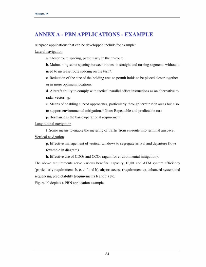
Annex A
84
ANNEX A - PBN APPLICATIONS - EXAMPLE
Airspace applications that can be developped include for example:
Lateral navigation
a. Closer route spacing, particularly in the en-route;
b. Maintaining same spacing between routes on straight and turning segments without a
need to increase route spacing on the turn*;
c. Reduction of the size of the holding area to permit holds to be placed closer together
or in more optimum locations;
d. Aircraft ability to comply with tactical parallel offset instructions as an alternative to
radar vectoring;
e. Means of enabling curved approaches, particularly through terrain rich areas but also
to support environmental mitigation.* Note: Repeatable and predictable turn
performance is the basic operational requirement.
Longitudinal navigation
f. Some means to enable the metering of traffic from en-route into terminal airspace;
Vertical navigation
g. Effective management of vertical windows to segregate arrival and departure flows
(example in diagram)
h. Effective use of CDOs and CCOs (again for environmental mitigation);
The above requirements serve various benefits: capacity, flight and ATM system efficiency
(particularly requirements b, c, e, f and h), airport access (requirement e), enhanced system and
sequencing predictability (requirements b and f ) etc.
Figure 40 depicts a PBN application example.

Annex A
85
Figure 40 – PBN application (Source EUROCONTROL)

Annex B
86
ANNEX B - KALMAN FILTERS
Kalman filtering, also known as Linear Quadratic Estimation (LQE), is an algorithm that uses a
series of measurements observed over time, containing noise (random variations) and other
inaccuracies, and produces estimates of unknown variables that tend to be more precise than
those based on a single measurement alone. More formally, the Kalman filter operates
recursively on streams of noisy input data to produce a statistically optimal estimate of the
underlying system state.
The Kalman filter has numerous applications in technology. A common application is for
guidance, navigation and control of vehicles, particularly aircraft and spacecraft. Furthermore,
the Kalman filter is a widely applied concept in time series analysis used in fields such as
signal processing.
The algorithm works in a two-step process. In the prediction step, the Kalman filter produces
estimates of the current state variables, along with their uncertainties. Once the outcome of the
next measurement (necessarily corrupted with some amount of error, including random noise)
is observed, these estimates are updated using a weighted average, with more weight being
given to estimates with higher certainty. Because of the algorithm's recursive nature, it can run
in real time using only the present input measurements and the previously calculated state and
its uncertainty matrix; no additional past information is required.
Extensions and generalizations to the method have also been developed, such as the extended
Kalman filter. The underlying model is a Bayesian model similar to a hidden Markov model
but where the state space of the latent variables is continuous and where all latent and observed
variables have Gaussian distributions.
All measurements and calculations based on models are estimates to some degree. Noisy
sensor data, approximations in the equations that describe how a system changes, and external
factors that are not accounted for introduce some uncertainty about the inferred values for a
system's state. The Kalman filter averages a prediction of a system's state with a new
measurement using a weighted average. The purpose of the weights is that values with better
(i.e. smaller) estimated uncertainty are "trusted" more. The weights are calculated from the
covariance, a measure of the estimated uncertainty of the prediction of the system's state. The

Annex B
87
result of the weighted average is a new state estimate that lies between the predicted and
measured state, and has a better estimated uncertainty than either alone. This process is
repeated every time step, with the new estimate and its covariance informing the prediction
used in the following iteration. This means that the Kalman filter works recursively and
requires only the last "best guess", rather than the entire history, of a system's state to calculate
a new state.
Because the certainty of the measurements is often difficult to measure precisely, it is common
to discuss the filter's behavior in terms of gain. The Kalman gain is a function of the relative
certainty of the measurements and current state estimate, and can be "tuned" to achieve
particular performance. With a high gain, the filter places more weight on the measurements,
and thus follows them more closely. With a low gain, the filter follows the model predictions
more closely, smoothing out noise but decreasing the responsiveness. At the extremes, a gain
of one causes the filter to ignore the state estimate entirely, while a gain of zero causes the
measurements to be ignored.
When performing the actual calculations for the filter (as discussed below), the state estimate
and covariances are coded into matrices to handle the multiple dimensions involved in a single
set of calculations. This allows for representation of linear relationships between different state
variables (such as position, velocity, and acceleration) in any of the transition models or
covariances.
Other authors say that Kalman Filters are a form of predictor-corrector used extensively in
control systems engineering for estimating unmeasured states of a process. The estimated states
may then be used as part of a strategy for control law design.
It's nearly impossible to grasp the full meaning of Kalman Filter by starting from definitions
and complicated equations. For most cases, the state matrices drop out and we obtain the below
equation, which is much easier to start with.
Remember, the k's on the subscript are states. Here we can treat it as discrete time intervals,
such as k=1 means 1ms, k=2 means 2ms.
Our purpose is to find kX̂ , the estimate of the signal x. And we wish to find it for each
consequent k's.
(Equation 9)

Annex B
88
Also here, kZ is the measurement value. Keep in mind that, we are not perfectly sure of these
values. Otherwise, we won't be needing to do all these. And kK is called "Kalman Gain"
(which is the key point of all these), and 1ˆ −kX is the estimate of the signal on the previous
state.
The only unknown component in this equation is the Kalman Gain kK . Because, we have the
measurement values, and we already have the previous estimated signal. You should calculate
this Kalman Gain for each consequent state. This is not easy of course, but we have all the
tools to do it.
On the other hand, let's assume kK to be 0.5, what do we get? It's a simple averaging! In other
words, we should find smarter kK coefficients at each state. The bottom line is:
Kalman filter finds the most optimum averaging factor for each consequent state. Also
somehow remembers a little bit about the past states.
The below graph (Figure 41) illustrates the estimates obtained with a kalman filter on the basis
of estimates and measurement.
Figure 41 – Result from Kalman Filter application
When a Kalman filter is used for target state estimation the process can be described as
follows:

Annex B
89
• Kalman filter estimates the states of the target using the process and measurement
models
• Two estimates of the state are distinguished: a conditional estimate conditioned on the
measurement history up to the current time and an estimate conditioned on the
measurement history up through the previous sample time
• There is an estimated state derived from the previous estimation and is known as
predicted state obtained from the process model with the time update
• The target state estimation using the Kalman filter is shown in Figure 42. The predicted
state and the current measurement are combined by the Kalman filter to get the current
estimated state.
Figure 42 – Estimation process
Additional details on Kalman filters can be found at:
http://bilgin.esme.org/BitsBytes/KalmanFilterforDummies.aspx
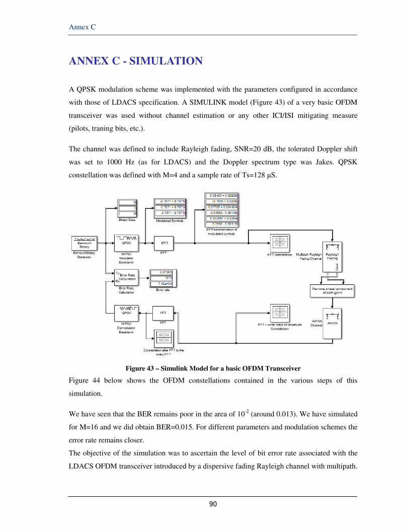
Annex C
90
ANNEX C - SIMULATION
A QPSK modulation scheme was implemented with the parameters configured in accordance
with those of LDACS specification. A SIMULINK model (Figure 43) of a very basic OFDM
transceiver was used without channel estimation or any other ICI/ISI mitigating measure
(pilots, traning bits, etc.).
The channel was defined to include Rayleigh fading, SNR=20 dB, the tolerated Doppler shift
was set to 1000 Hz (as for LDACS) and the Doppler spectrum type was Jakes. QPSK
constellation was defined with M=4 and a sample rate of Ts=128 µS.
Figure 43 – Simulink Model for a basic OFDM Transceiver
Figure 44 below shows the OFDM constellations contained in the various steps of this
simulation.
We have seen that the BER remains poor in the area of 10-2 (around 0.013). We have simulated
for M=16 and we did obtain BER=0.015. For different parameters and modulation schemes the
error rate remains closer.
The objective of the simulation was to ascertain the level of bit error rate associated with the
LDACS OFDM transceiver introduced by a dispersive fading Rayleigh channel with multipath.

Annex C
91
The next step was to verify the improvement to be offered by channel estimation using a
Kalman filter.
For that purpose, a MATLAB script simulating the Kalman channel estimation for OFDM (see
it at the end of this annex) was run also on the basis of LDACS parameters. Two parallel filters
were used. The results are depicted in Figures 41 and 42.
Figure 44 – Spectrum and OFDM Constelation
Matlab script simulating the Kalman channel estimation for OFDM
% File Name : main_Kalman_CE.m % Description: Time varying channel estimation using Kalman filter % % % % % % % % % % % % % % % % % % % % % % % % % % % % % % % % % % % clear all; close all; % % % % % % % % % % % % Parameter Define % % % % % % % % % % % % N = 101; % number of observation p = 2; % number of multipath A = [0.99 0; 0 0.999];

Annex C
92
sigma_u = 0.01; Q = [sigma_u^2 0; 0 sigma_u^2]; sigma = sqrt(0.1); % observation noise S.D H = [1; .9]; % h[-1] h_hat_1 = [0; 0]; % initial channel state, h_hat[-1|-1] M_1 = 100*eye(p); % initial MMSE val, M[-1|-1] w = sigma*randn; v = [zeros(5,1); ones(5,1);zeros(5,1); ones(5,1)]; v = [v;v;v;v;v;v]; % channel input, v[n] % % % % % % % % % % % % % % % % % % % % % % % % % % % % % % % % % % % % % h_mat_True = zeros(p,N); h_mat_Est= zeros(p,N); K_mat= zeros(p,N); M_mat= zeros(p,N); x_free_vec = zeros(1,N); x_vec= zeros(1,N); for n = 1 : N-1 U = sigma_u*randn(p,1); H = A*H+U; % unknown channel update V = [ v(n+1);v(n) ]; % known input w = sigma*randn; % wgn x_free = V'*H ; % Noiseless channel output x = x_free + w; % Channel Output h_hat_2 = A*h_hat_1; M_2 = A*M_1*A'+Q; K = ( M_2*V )./ ( sigma^2 + V'*M_2*V ); h_hat_1 = h_hat_2 + K*(x -V'*h_hat_2 ); M_1 = ( eye(p) - K*V' )*M_2; % % % for plotting % % % x_vec(n) = x; x_free_vec(n) = x_free; h_mat_True(:,n) = H; h_mat_Est(:,n) = h_hat_2; K_mat(:,n) = K; M_mat(:,n) = [ M_1(1,1); M_1(2,2) ]; end figure(1); %title('Realization of TDL coefficients'); subplot(2,1,1); plot(h_mat_True(1,1:100), '--', 'LineWidth', 2); hold on; grid on; plot(h_mat_Est(1,1:100),'r', 'LineWidth', 2); xlabel('Sample number, n'); ylabel('Tap weight, h_n[0]'); legend('True','Estimate'); ylim( [0 2] ) subplot(2,1,2); plot(h_mat_True(2,1:100), '--', 'LineWidth', 2); hold on; grid on; plot(h_mat_Est(2,1:100), 'r', 'LineWidth', 2); xlabel('Sample number, n'); ylabel('Tap weight, h_n[1]'); legend('True','Estimate'); ylim( [0 2] ) figure(2); subplot(3,1,1);

Annex C
93
plot(v(1:100), 'LineWidth', 2); xlabel('Sample number, n'); ylabel('Channel input, v[n]'); ylim( [-1 2.5] ) subplot(3,1,2); plot(x_free_vec(1,1:100), 'LineWidth', 2); xlabel('Sample number, n'); ylabel('Noiseless channel, y[n]'); ylim( [-1 2.5] ) subplot(3,1,3); plot(x_vec(1,1:100), 'LineWidth', 2); xlabel('Sample number, n'); ylabel('Channel input, v[n]'); ylim( [-1 2.5] ) figure(3); subplot(2,1,1); plot(K_mat(1,1:100), 'LineWidth', 2); xlabel('Sample number, n'); ylabel('Kalman gain, K_1[n]'); ylim( [-.6 1.1] ) subplot(2,1,2); plot(K_mat(2,1:100), 'LineWidth', 2); xlabel('Sample number, n'); ylabel('Kalman gain, K_2[n]'); ylim( [-.6 1.1] ) figure(4) subplot(2,1,1); plot(M_mat(1,1:100), 'LineWidth', 2); xlabel('Sample number, n'); ylabel('Min. MSE, M_11[n]'); ylim( [0 0.2] ) subplot(2,1,2); plot(M_mat(2,1:100), 'LineWidth', 2); xlabel('Sample number, n'); ylabel('Min. MSE, M_22[n]'); ylim( [0 0.2] ) EDU>> EDU>> % File Name : main_Kalman_CE.m % Description: Time varying channel estimation using Kalman filter % % Date : 2009.8.3. (by chano.) % % % % % % % % % % % % % % % % % % % % % % % % % % % % % % % % % % % % clear all; close all; % % % % % % % % % % % % Parameter Define % % % % % % % % % % % % N = 101; % number of observation p = 2; % number of multipath A = [0.99 0; 0 0.999]; sigma_u = 0.01; Q = [sigma_u^2 0; 0 sigma_u^2]; sigma = sqrt(0.1); % observation noise S.D H = [1; .9]; % h[-1] h_hat_1 = [0; 0]; % initial channel state, h_hat[-1|-1] M_1 = 100*eye(p); % initial MMSE val, M[-1|-1] w = sigma*randn;

Annex C
94
v = [zeros(5,1); ones(5,1);zeros(5,1); ones(5,1)]; v = [v;v;v;v;v;v]; % channel input, v[n] % % % % % % % % % % % % % % % % % % % % % % % % % % % % % % % % % % % % % h_mat_True = zeros(p,N); h_mat_Est= zeros(p,N); K_mat= zeros(p,N); M_mat= zeros(p,N); x_free_vec = zeros(1,N); x_vec= zeros(1,N); for n = 1 : N-1 U = sigma_u*randn(p,1); H = A*H+U; % unknown channel update V = [ v(n+1);v(n) ]; % known input w = sigma*randn; % wgn x_free = V'*H ; % Noiseless channel output x = x_free + w; % Channel Output h_hat_2 = A*h_hat_1; M_2 = A*M_1*A'+Q; K = ( M_2*V )./ ( sigma^2 + V'*M_2*V ); h_hat_1 = h_hat_2 + K*(x -V'*h_hat_2 ); M_1 = ( eye(p) - K*V' )*M_2; % % % for plotting % % % x_vec(n) = x; x_free_vec(n) = x_free; h_mat_True(:,n) = H; h_mat_Est(:,n) = h_hat_2; K_mat(:,n) = K; M_mat(:,n) = [ M_1(1,1); M_1(2,2) ]; end figure(1); %title('Realization of TDL coefficients'); subplot(2,1,1); plot(h_mat_True(1,1:100), '--', 'LineWidth', 2); hold on; grid on; plot(h_mat_Est(1,1:100),'r', 'LineWidth', 2); xlabel('Sample number, n'); ylabel('Tap weight, h_n[0]'); legend('True','Estimate'); ylim( [0 2] ) subplot(2,1,2); plot(h_mat_True(2,1:100), '--', 'LineWidth', 2); hold on; grid on; plot(h_mat_Est(2,1:100), 'r', 'LineWidth', 2); xlabel('Sample number, n'); ylabel('Tap weight, h_n[1]'); legend('True','Estimate'); ylim( [0 2] ) figure(2); subplot(3,1,1); plot(v(1:100), 'LineWidth', 2); xlabel('Sample number, n'); ylabel('Channel input, v[n]'); ylim( [-1 2.5] ) subplot(3,1,2); plot(x_free_vec(1,1:100), 'LineWidth', 2); xlabel('Sample number, n');

Annex C
95
ylabel('Noiseless channel, y[n]'); ylim( [-1 2.5] ) subplot(3,1,3); plot(x_vec(1,1:100), 'LineWidth', 2); xlabel('Sample number, n'); ylabel('Channel input, v[n]'); ylim( [-1 2.5] ) figure(3); subplot(2,1,1); plot(K_mat(1,1:100), 'LineWidth', 2); xlabel('Sample number, n'); ylabel('Kalman gain, K_1[n]'); ylim( [-.6 1.1] ) subplot(2,1,2); plot(K_mat(2,1:100), 'LineWidth', 2); xlabel('Sample number, n'); ylabel('Kalman gain, K_2[n]'); ylim( [-.6 1.1] ) figure(4) subplot(2,1,1); plot(M_mat(1,1:100), 'LineWidth', 2); xlabel('Sample number, n'); ylabel('Min. MSE, M_11[n]'); ylim( [0 0.2] ) subplot(2,1,2); plot(M_mat(2,1:100), 'LineWidth', 2); xlabel('Sample number, n'); ylabel('Min. MSE, M_22[n]'); ylim( [0 0.2] )

96
[End of the Document]
Top Related