


Línguas
Páginas
Legal

Database System Concepts, 5th Ed.
©Silberschatz, Korth and SudarshanSee www.db-book.com for conditions on re-use
Capítulo 11: Armazenamento e Capítulo 11: Armazenamento e Estrutura de ArquivosEstrutura de Arquivos
©Silberschatz, Korth and Sudarshan11.2Database System Concepts - 5th Edition, Oct 23, 2005.
Chapter 11: Storage and File StructureChapter 11: Storage and File Structure
Overview of Physical Storage Media
Magnetic Disks
RAID
Tertiary Storage
Storage Access
File Organization
Organization of Records in Files
Data-Dictionary Storage
Storage Structures for Object-Oriented Databases

©Silberschatz, Korth and Sudarshan11.3Database System Concepts - 5th Edition, Oct 23, 2005.
Classificação de mídia de armazenamento Classificação de mídia de armazenamento
Velocidade de acesso aos dados
Custo por unidade de dados
Confiabilidade
Perda de dados em caso de falha do sistema
Falha física do dispositivo
Dispositivos de armazenamento podem ser:
voláteis: perdem o conteúdo em caso de falta de energia
não-voláteis:
Conteúdo persiste mesmo sem energia.
Inclui armazenamento secundário e terciário assim como memória principal protegida por bateria.

©Silberschatz, Korth and Sudarshan11.4Database System Concepts - 5th Edition, Oct 23, 2005.
Mídia de Armazenamento FísicoMídia de Armazenamento Físico
Cache – mais rápida e mais cara forma de armazenamento; volátil; gerenciada pelo hardware do computador.
Memória principal:
Acesso rápido (dezenas a centenas de nanossegundos; 1 nanossegundo = 10–9 segundo)
Geralmente muito pequena (ou muito cara) para armazenar todo o banco de dados
Capacidade de até vários Gigabytes usadas atualmente
Capacidades tem crescido e o custo por byte tem diminuído rapidamente (aproximadamente um fator de 2 a cada 2 ou 3 anos)
Volátil — conteúdo é geralmente perdido em caso de falha de hardware ou falta de energia.

©Silberschatz, Korth and Sudarshan11.5Database System Concepts - 5th Edition, Oct 23, 2005.
Mídia de Armazenamento Físico (Cont.)Mídia de Armazenamento Físico (Cont.)
Memória flash
Dados são preservados em caso de falha de energia
Dados podem ser escritos somente uma vez em uma área, mas a área pode ser apagada e reutilizada
Suporta uma número limitado (10K – 1M) de ciclos de escrita/apagamento
Apagamento da memória precisa ser feito em todo um banco de memória
Leituras são quase tão rápidas quanto em memória principal
Escritas são lentas (alguns microssegundos), apagamento é mais lento
Custo por unidade de armazenamento é similar à memória principal
É um tipo de EEPROM (Electrically Erasable Programmable Read-Only Memory)

©Silberschatz, Korth and Sudarshan11.6Database System Concepts - 5th Edition, Oct 23, 2005.
Mídia de Armazenamento Físico (Cont.)Mídia de Armazenamento Físico (Cont.)
Disco magnético Dados armazenados em um disco giratório e lidos/escritos
magneticamente
Meio primário de armazenamento a longo prazao; tipicamente armazena todo o banco de dados
Dados precisam ser movidos para a memória principal para acesso e escritos novamente para armazenamento
Acesso muito mais lento que memória principal
Acesso direto – é possível ler dados em qualquer ordem
Capacidades atingem 3TB atualmente
Capacidade muito maior e custo/byte que memória principal e flash
Capacidade crescente com melhorias da tecnologia
Sobrevive e quedas de energia e problemas de hardware
Falha do disco pode destruir os dados, mas é raro

©Silberschatz, Korth and Sudarshan11.7Database System Concepts - 5th Edition, Oct 23, 2005.
Mídia de Armazenamento Físico (Cont.)Mídia de Armazenamento Físico (Cont.)
Armazenamento ótico
Não volátil, dados são lidos oticamente de um disco giratório por um laser
CD-ROM (640 MB) e DVD (4.7 to 17 GB) são os mais populares
Discos write-one, read-many (WORM) usados para arquivo (CD-R, DVD-R, DVD+R)
Existem versões multi-gravação (CD-RW, DVD-RW, DVD+RW, and DVD-RAM)
Leituras e escritas são mais lentas que em discos magnéticos

©Silberschatz, Korth and Sudarshan11.8Database System Concepts - 5th Edition, Oct 23, 2005.
Mídia de Armazenamento Físico (Cont.)Mídia de Armazenamento Físico (Cont.)
Armazenamento em fita magnética
Não volátil, usado principalmente para backup (recuperação de disco) e arquivo
Acesso sequencial – muito mais lento que disco
Capacidade muito alta (40 to 300 GB)
Fita pode ser removida do drive custo de armazenamento muito menor que disco mas drives são caros
Jukeboxes de fitas disponíveis para armazenamento de grandes quantidades de dados
Centenas de terabytes (1 terabyte = 109 bytes) e até mesmo 1 petabyte (1 petabyte = 1012 bytes)

©Silberschatz, Korth and Sudarshan11.9Database System Concepts - 5th Edition, Oct 23, 2005.
Hierarquia de ArmazenamentoHierarquia de Armazenamento

©Silberschatz, Korth and Sudarshan11.10Database System Concepts - 5th Edition, Oct 23, 2005.
Hierarquia de Armazenamento (Cont.)Hierarquia de Armazenamento (Cont.)
Armazenamento primário: mídia rápida mas volátil (cache, memória principal).
Armazenamento secundário: não volátil, tempo de acesso moderadamento rápido
Também chamado de armazenamento on-line
P. ex. memória flash, discos magnéticos
Armazenamento terciário: não volátil, tempo de acesso alto
Também chamado de armazenamento off-line
P. ex. fita magnética, armazenamento ótico

©Silberschatz, Korth and Sudarshan11.11Database System Concepts - 5th Edition, Oct 23, 2005.
Mecanismo do Disco RígidoMecanismo do Disco Rígido
NOTA: diagrama esquemático simplificado de um disco real
©Silberschatz, Korth and Sudarshan11.12Database System Concepts - 5th Edition, Oct 23, 2005.
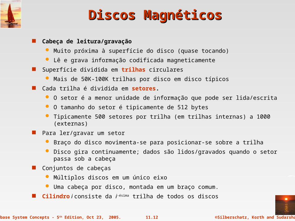
Discos MagnéticosDiscos Magnéticos
Cabeça de leitura/gravação
Muito próxima à superfície do disco (quase tocando)
Lê e grava informação codificada magneticamente
Superfície dividida em trilhas circulares
Mais de 50K-100K trilhas por disco em disco típicos
Cada trilha é dividida em setores.
O setor é a menor unidade de informação que pode ser lida/escrita
O tamanho do setor é tipicamente de 512 bytes
Tipicamente 500 setores por trilha (em trilhas internas) a 1000 (externas)
Para ler/gravar um setor
Braço do disco movimenta-se para posicionar-se sobre a trilha
Disco gira continuamente; dados são lidos/gravados quando o setor passa sob a cabeça
Conjuntos de cabeças
Múltiplos discos em um único eixo
Uma cabeça por disco, montada em um braço comum.
Cilindro i consiste da i-ésima trilha de todos os discos
©Silberschatz, Korth and Sudarshan11.13Database System Concepts - 5th Edition, Oct 23, 2005.
Discos Magnéticos (Cont.)Discos Magnéticos (Cont.)
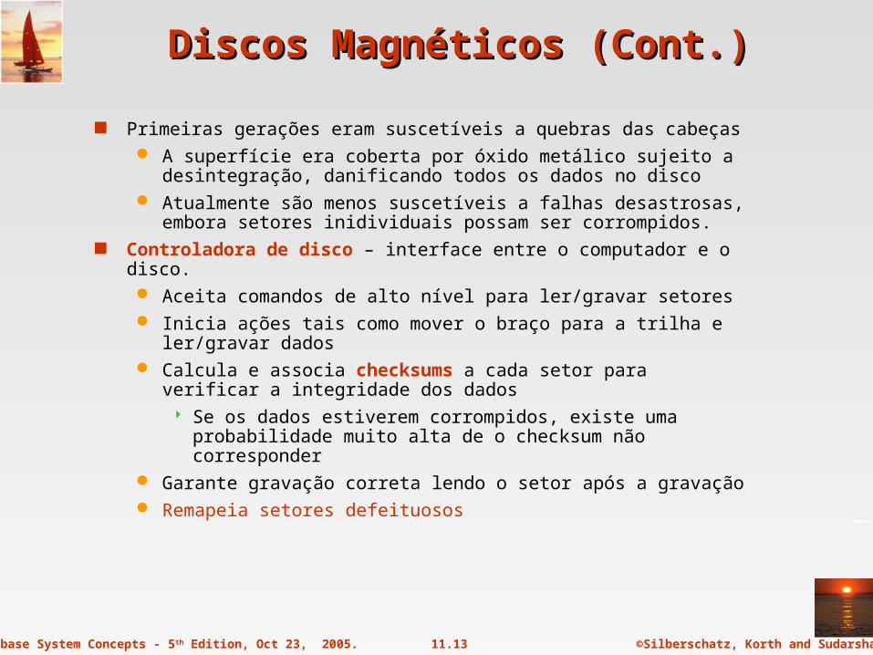
Primeiras gerações eram suscetíveis a quebras das cabeças A superfície era coberta por óxido metálico sujeito a desintegração,
danificando todos os dados no disco Atualmente são menos suscetíveis a falhas desastrosas, embora
setores inidividuais possam ser corrompidos. Controladora de disco – interface entre o computador e o disco.
Aceita comandos de alto nível para ler/gravar setores Inicia ações tais como mover o braço para a trilha e ler/gravar
dados Calcula e associa checksums a cada setor para verificar a
integridade dos dados Se os dados estiverem corrompidos, existe uma probabilidade
muito alta de o checksum não corresponder Garante gravação correta lendo o setor após a gravação Remapeia setores defeituosos

©Silberschatz, Korth and Sudarshan11.14Database System Concepts - 5th Edition, Oct 23, 2005.
Subsistema de DiscosSubsistema de Discos
Múltiplos discos conectados a um computador por uma controladora Funcionalidade da controladora (checksum, remapeamento) realizada
pelos discos individuais; reduz a carga sobre a controladora Famílias de interfaces de disco
Padrões ATA (adaptador AT) SATA (Serial ATA) Padrões SCSI (Small Computer System Interconnect) Muitas variantes de cada padrão (velocidades e capacidades)
©Silberschatz, Korth and Sudarshan11.15Database System Concepts - 5th Edition, Oct 23, 2005.
Medidas de Desempenho de DiscosMedidas de Desempenho de Discos
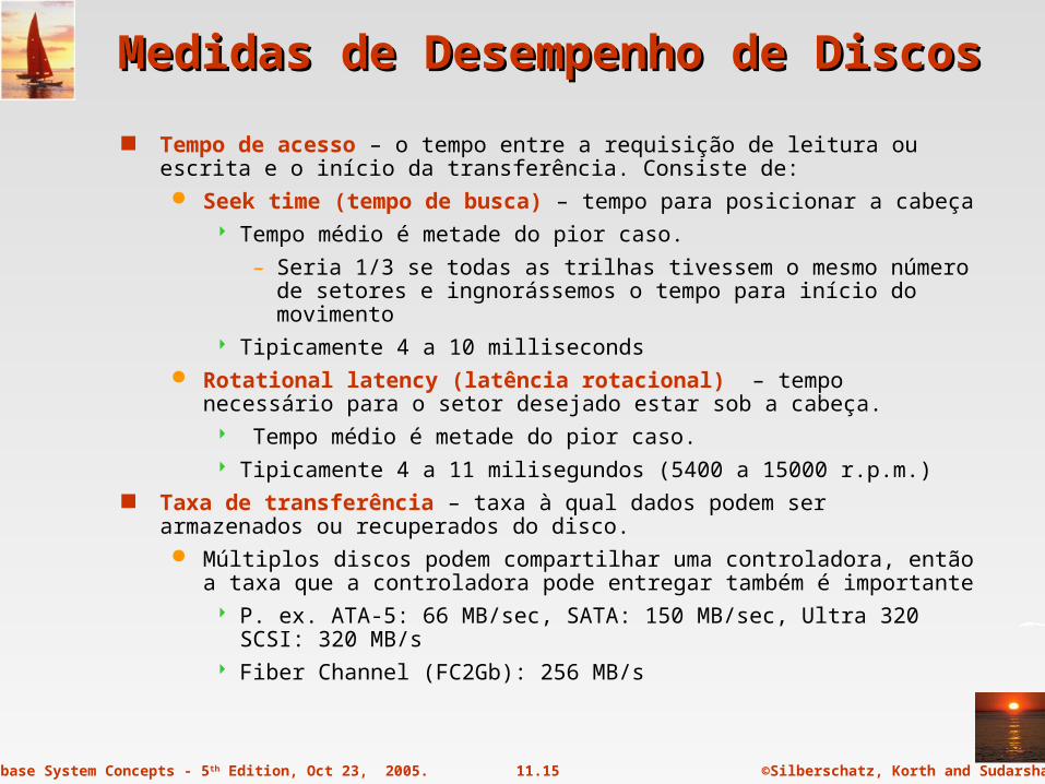
Tempo de acesso – o tempo entre a requisição de leitura ou escrita e o início da transferência. Consiste de: Seek time (tempo de busca) – tempo para posicionar a cabeça
Tempo médio é metade do pior caso.
– Seria 1/3 se todas as trilhas tivessem o mesmo número de setores e ingnorássemos o tempo para início do movimento
Tipicamente 4 a 10 milliseconds Rotational latency (latência rotacional) – tempo necessário para o
setor desejado estar sob a cabeça. Tempo médio é metade do pior caso. Tipicamente 4 a 11 milisegundos (5400 a 15000 r.p.m.)
Taxa de transferência – taxa à qual dados podem ser armazenados ou recuperados do disco. Múltiplos discos podem compartilhar uma controladora, então a taxa que
a controladora pode entregar também é importante P. ex. ATA-5: 66 MB/sec, SATA: 150 MB/sec, Ultra 320 SCSI: 320
MB/s Fiber Channel (FC2Gb): 256 MB/s
©Silberschatz, Korth and Sudarshan11.16Database System Concepts - 5th Edition, Oct 23, 2005.
Medidas de Desempenho (Cont.)Medidas de Desempenho (Cont.)
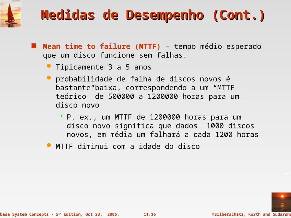
Mean time to failure (MTTF) – tempo médio esperado que um disco funcione sem falhas.
Tipicamente 3 a 5 anos
probabilidade de falha de discos novos é bastante baixa, correspondendo a um “MTTF teórico” de 500000 a 1200000 horas para um disco novo
P. ex., um MTTF de 1200000 horas para um disco novo significa que dados 1000 discos novos, em média um falhará a cada 1200 horas
MTTF diminui com a idade do disco

©Silberschatz, Korth and Sudarshan11.17Database System Concepts - 5th Edition, Oct 23, 2005.
Otimização de acesso a blocosOtimização de acesso a blocos
Bloco – sequência de setores de uma mesma trilha
Dados são transferidos para a memória em blocos
Tamanhos variam de 512 bytes a vários kilobytes
Blocos menores: mais transferências do disco
Blocos maiores: mais espaços desperdiçado com blocos parcialmente preenchidos
Tamanhos típicos variam de 4 a 16KB
Algorítmos de agendamento de braço de disco ordenam acessos pendentes a trilhas de modo a minimizar o movimento
Algoritmo do elevador : move o braço em uma única direção (interno para externo e vice-versa), processando a próxima requisição nesta direção enquanto houverem requisições nesta direção, então reverte a direção e repete

©Silberschatz, Korth and Sudarshan11.18Database System Concepts - 5th Edition, Oct 23, 2005.
Otimização de acesso a blocos (Cont.)Otimização de acesso a blocos (Cont.)
Organização de arquivos – otimizar o tempo de acesso a blocos organizando-os ao modo como os dados serão acessados
P. ex. Armazenar informação relacionada em cilindros próximos.
Arquivos podem ficar fragmentados com o tempo
P. ex. Dados inseridos/excluídos do arquivo
Blocos livres em arquivos ficam espalhados pelo disco
Acesso sequencial a arquivos fragmentados resulta em aumento do movimento do braço
Alguns sistemas tem utilitários para desfragmentar o sistema de aquivos a fim de acelerar o acesso a arquivos.

©Silberschatz, Korth and Sudarshan11.19Database System Concepts - 5th Edition, Oct 23, 2005.
Buffers de escrita não voláteis aceleram a escrita gravando blocos em memória não volátil imediatamente
RAM não volátil: protegida por bateria ou flash
Mesmo em caso de falha de energia os dados são preservados e gravados quando a energia é restabelecida
A controladora grava no disco quando não há outras requisições pendentes
Operações de banco de dados que requerem que os dados sejam salvos antes de continuar podem prosseguir sem esperar pela gravação no disco
Gravações podem ser reordenadas para minimizar o movimento do braço
Disco de log – um disco dedicado a gravações sequenciais de atualizações de blocos
Usado exatamente como memória RAM não volátil
Gravação é muito rápida uma vez que seeks não são necessários
Sem necessidade de hardware especial (NV-RAM)
Sistemas de arquivos tipicamente reordenam gravações
Journaling file systems gravam dados em ordem segura para NV-RAM ou log
Reordenar sem journaling: risco de corrupção de dados
Otimização de acesso a blocos (Cont.)Otimização de acesso a blocos (Cont.)

©Silberschatz, Korth and Sudarshan11.20Database System Concepts - 5th Edition, Oct 23, 2005.
RAIDRAID
RAID: Redundant Arrays of Independent Disks Técnicas de organização de discos que gerenciam grande número de
discos oferecendo um visão única do disco Alta capacidade e alta velocidade usando múltiplos discos em
paralelo, e Alta confiabilidade armazenando dados redundantes, de modo
que os dados possam ser recuperados em caso de falha de disco A chance de algum disco de um conjunto de N discos falhar é muito mais
alta que a de um disco específico falhar P. ex., um sistema com 100 discos, cada um com MTTF de 100000
horas (aprox. 11 anos), terá um MTTF de 1000 horas (aprox. 41 dias)
Técnicas de redundância para evitar perda de dados são críticas com um grande número de discos
Originalmente usado com alternativa para discos caros I in RAID originalmente significava ``inexpensive’’ Atualmente RAIDs são usados por sua alta confiabilidade e
velocidade. O “I” é interpretado como independente
©Silberschatz, Korth and Sudarshan11.21Database System Concepts - 5th Edition, Oct 23, 2005.
Melhoria de Confiabilidade via RedundânciaMelhoria de Confiabilidade via Redundância
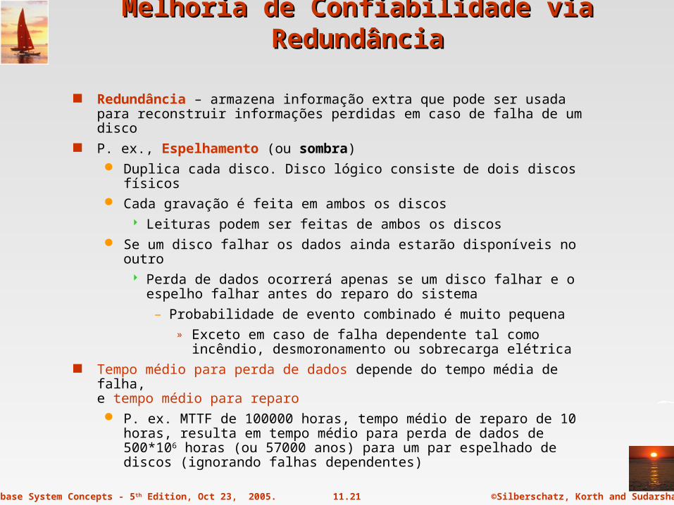
Redundância – armazena informação extra que pode ser usada para reconstruir informações perdidas em caso de falha de um disco
P. ex., Espelhamento (ou sombra) Duplica cada disco. Disco lógico consiste de dois discos físicos Cada gravação é feita em ambos os discos
Leituras podem ser feitas de ambos os discos Se um disco falhar os dados ainda estarão disponíveis no outro
Perda de dados ocorrerá apenas se um disco falhar e o espelho falhar antes do reparo do sistema
– Probabilidade de evento combinado é muito pequena» Exceto em caso de falha dependente tal como incêndio,
desmoronamento ou sobrecarga elétrica Tempo médio para perda de dados depende do tempo média de falha,
e tempo médio para reparo P. ex. MTTF de 100000 horas, tempo médio de reparo de 10 horas,
resulta em tempo médio para perda de dados de 500*106 horas (ou 57000 anos) para um par espelhado de discos (ignorando falhas dependentes)

©Silberschatz, Korth and Sudarshan11.22Database System Concepts - 5th Edition, Oct 23, 2005.
Melhoria de Desempenho via ParalelismoMelhoria de Desempenho via Paralelismo
Dois objetivos principais do paralelismo em um sistema de discos
1. Balanceamento de carga em pequenos acessos para aumentar a taxa de transferência (throughput)
2. Grandes acessos em paralelo reduzem o tempo de resposta
Melhora a taxa de transferência espalhando os dados em vários discos
Espalhamento de bits – espalha os bits de cada byte em vários discos
Em um conjunto de oito discos, escreve o bit i de cada byte no disco i.
Cada acesso pode ler dados 8 vezes mais rápido que em um disco
Tempo de busca/acesso pior que em um único disco
Não é mais usado atualmente
Espalhamento de blocos – com n discos, o bloco i de um arquivo vai para o disco (i mod n) + 1
Requisições para diferentes blocos podem ser atendidas em paralelo se os blocos estiverem em discos diferentes
Uma requisição para um sequência longa de blocos pode utilizar todos os discos em paralelo
©Silberschatz, Korth and Sudarshan11.23Database System Concepts - 5th Edition, Oct 23, 2005.
Níveis de RAIDNíveis de RAID
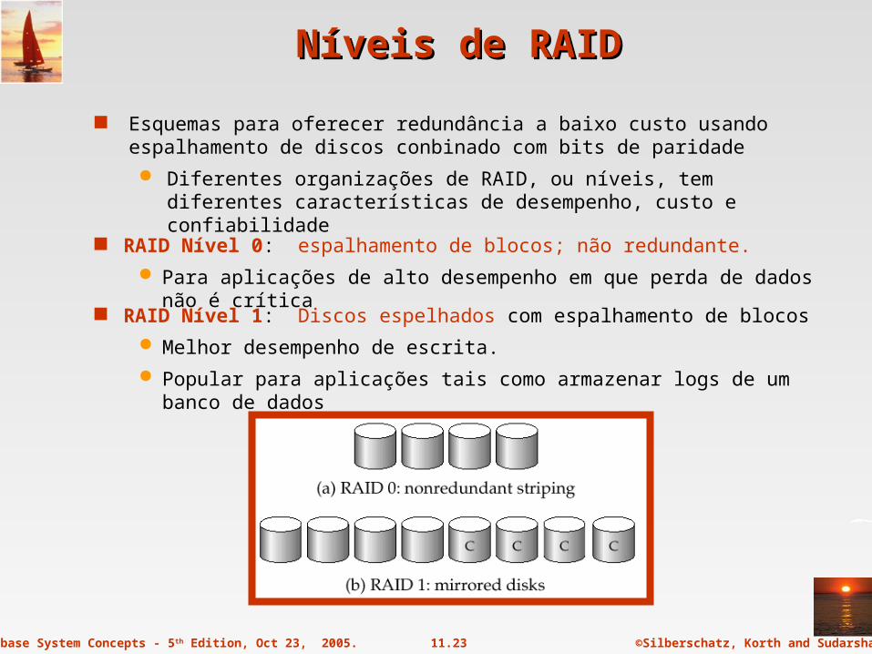
Esquemas para oferecer redundância a baixo custo usando espalhamento de discos conbinado com bits de paridade
Diferentes organizações de RAID, ou níveis, tem diferentes características de desempenho, custo e confiabilidade
RAID Nível 1: Discos espelhados com espalhamento de blocos
Melhor desempenho de escrita.
Popular para aplicações tais como armazenar logs de um banco de dados
RAID Nível 0: espalhamento de blocos; não redundante.
Para aplicações de alto desempenho em que perda de dados não é crítica

©Silberschatz, Korth and Sudarshan11.24Database System Concepts - 5th Edition, Oct 23, 2005.
Níveis de RAID (Cont.)Níveis de RAID (Cont.)
RAID Nível 2: Códigos de correção de erro (ECC) com espalhamento de bits.
RAID Nível 3: Paridade com bits intercalados
Um único bit de paridade é suficiente para correção de erros, não apenas detecção, uma vez que sabemos qual disco falhou
Ao escrever dados, bits de paridade precisam ser calculados e escritos no disco de bits de paridade
Para recuperar dados de um disco danificado, calcula-se XOR de bits de outros discos (incluindo o disco de bits de paridade)

©Silberschatz, Korth and Sudarshan11.25Database System Concepts - 5th Edition, Oct 23, 2005.
Níveis de RAID (Cont.)Níveis de RAID (Cont.)
RAID Nível 3 (Cont.)
Taxa de transferência mais rápida que um único disco mas menos I/O por segundo uma vez que cada disco participa em todo I/O
Melhor que nível 2 (todos os benefícios a um custo menor)
RAID Nível 4: Paridade de blocos intercalados; usa espalhamento de blocos e mantem um bloco de paridade em um disco separado para blocos de N outros discos.
Ao gravar um bloco de dados, o bloco de paridade correspondente também precisa ser calculado e escrito no disco de paridade
Para encontrar o valor de um bloco danificado calcula-se o XOR de bits dos blocos correspondentes (incluindo o bloco de paridade) de outros discos.

©Silberschatz, Korth and Sudarshan11.26Database System Concepts - 5th Edition, Oct 23, 2005.
Níveis de RAID (Cont.)Níveis de RAID (Cont.)
RAID Nível 4 (Cont.)
Provides higher I/O rates for independent block reads than Level 3
block read goes to a single disk, so blocks stored on different disks can be read in parallel
Provides high transfer rates for reads of multiple blocks than no-striping
Before writing a block, parity data must be computed
Can be done by using old parity block, old value of current block and new value of current block (2 block reads + 2 block writes)
Or by recomputing the parity value using the new values of blocks corresponding to the parity block
– More efficient for writing large amounts of data sequentially
Parity block becomes a bottleneck for independent block writes since every block write also writes to parity disk
©Silberschatz, Korth and Sudarshan11.27Database System Concepts - 5th Edition, Oct 23, 2005.
Níveis de RAID (Cont.)Níveis de RAID (Cont.)
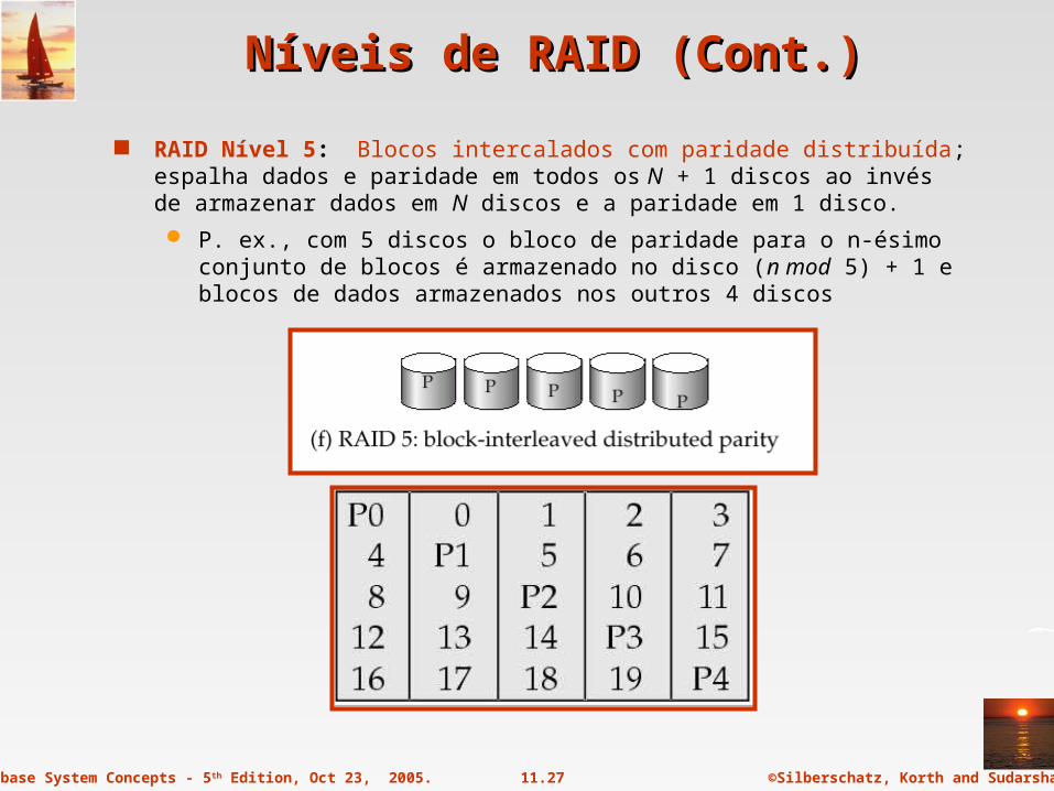
RAID Nível 5: Blocos intercalados com paridade distribuída; espalha dados e paridade em todos os N + 1 discos ao invés de armazenar dados em N discos e a paridade em 1 disco.
P. ex., com 5 discos o bloco de paridade para o n-ésimo conjunto de blocos é armazenado no disco (n mod 5) + 1 e blocos de dados armazenados nos outros 4 discos
©Silberschatz, Korth and Sudarshan11.28Database System Concepts - 5th Edition, Oct 23, 2005.
Níveis de RAID (Cont.)Níveis de RAID (Cont.)
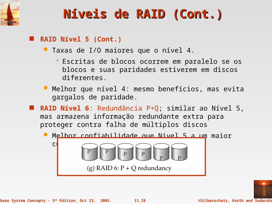
RAID Nível 5 (Cont.)
Taxas de I/O maiores que o nível 4.
Escritas de blocos ocorrem em paralelo se os blocos e suas paridades estiverem em discos diferentes.
Melhor que nível 4: mesmo benefícios, mas evita gargalos de paridade.
RAID Nível 6: Redundância P+Q; similar ao Nível 5, mas armazena informação redundante extra para proteger contra falha de múltiplos discos
Melhor confiabilidade que Nivel 5 a um maior custo
©Silberschatz, Korth and Sudarshan11.29Database System Concepts - 5th Edition, Oct 23, 2005.
Escolha de Nível de RAIDEscolha de Nível de RAID
Fatores na escolha de nível de RAID Custo Desempenho: Número de operações de I/O por segundo e taxa de
transferência em operação norml Desempenho durante falhas Desempenho durante reconstrução de discos falhos
Inclui tempo necessário à reconstrução de discos falhos RAID 0 é usado somente quando segurança não é importante
P. ex., dados podem ser recuperados facilmente de outras fontes Níveis 2 e 4 nunca usados uma vez que são superados pelos níveis 3 e 5 Nível 3 não é usado uma vez que a leitura de um único bloco requer o
acesso a todos os discos devido ao espalhamento de bits Nível 6 raramente é usado uma vez que os níveis 1 e 5 são
adequadamente seguros para a maioria das aplicações. Então a escolha recai sobre os níveis 1 e 5
©Silberschatz, Korth and Sudarshan11.30Database System Concepts - 5th Edition, Oct 23, 2005.
Escolha de Nível de RAID (Cont.)Escolha de Nível de RAID (Cont.)
Nível 1 oferece desempenho de gravação muito melhor que o nível 5
Nível 5 requer no mínimo duas leituras de bloco e 2 gravações de bloco para um único bloco, nível 1 requer apenas 2 gravações de bloco
Nível 1 é preferido para ambientes com alta taxa de atualização tais como discos de log
Nível 1 tinha custo de armazenamento maior que nível 5
Capacidades dos drives aumenta rapidamente enquanto o tempo de acesso diminui muito menos
Necessidades de I/O aumentaram muito, p. ex. servidores web
Quando discos suficientes tiverem sido adquiridos para satisfazer a taxa de I/O requerida, eles normalmente tem capacidade livre
When enough disks have been bought to satisfy required rate of I/O, they often have spare storage capacity
Então não há custo extra para o nível 1!
Nível 5 é preferido para aplicações com baixa taxa de atualizações e grandes volumes de dados.
Nível 1 é preferido para todas as outras aplicações
©Silberschatz, Korth and Sudarshan11.31Database System Concepts - 5th Edition, Oct 23, 2005.
Hardware IssuesHardware Issues
Software RAID: RAID implementations done entirely in software, with no special hardware support
Hardware RAID: RAID implementations with special hardware
Use non-volatile RAM to record writes that are being executed
Beware: power failure during write can result in corrupted disk
E.g. failure after writing one block but before writing the second in a mirrored system
Such corrupted data must be detected when power is restored
– Recovery from corruption is similar to recovery from failed disk
– NV-RAM helps to efficiently detected potentially corrupted blocks
» Otherwise all blocks of disk must be read and compared with mirror/parity block

©Silberschatz, Korth and Sudarshan11.32Database System Concepts - 5th Edition, Oct 23, 2005.
Hardware Issues (Cont.)Hardware Issues (Cont.)
Hot swapping: replacement of disk while system is running, without power down
Supported by some hardware RAID systems,
reduces time to recovery, and improves availability greatly
Many systems maintain spare disks which are kept online, and used as replacements for failed disks immediately on detection of failure
Reduces time to recovery greatly
Many hardware RAID systems ensure that a single point of failure will not stop the functioning of the system by using
Redundant power supplies with battery backup
Multiple controllers and multiple interconnections to guard against controller/interconnection failures
©Silberschatz, Korth and Sudarshan11.33Database System Concepts - 5th Edition, Oct 23, 2005.
Optical DisksOptical Disks
Compact disk-read only memory (CD-ROM) Removable disks, 640 MB per disk Seek time about 100 msec (optical read head is heavier and slower) Higher latency (3000 RPM) and lower data-transfer rates (3-6 MB/s)
compared to magnetic disks Digital Video Disk (DVD)
DVD-5 holds 4.7 GB , and DVD-9 holds 8.5 GB DVD-10 and DVD-18 are double sided formats with capacities of 9.4
GB and 17 GB Slow seek time, for same reasons as CD-ROM
Record once versions (CD-R and DVD-R) are popular data can only be written once, and cannot be erased. high capacity and long lifetime; used for archival storage Multi-write versions (CD-RW, DVD-RW, DVD+RW and DVD-RAM)
also available

©Silberschatz, Korth and Sudarshan11.34Database System Concepts - 5th Edition, Oct 23, 2005.
Magnetic TapesMagnetic Tapes
Hold large volumes of data and provide high transfer rates Few GB for DAT (Digital Audio Tape) format, 10-40 GB with DLT
(Digital Linear Tape) format, 100 GB+ with Ultrium format, and 330 GB with Ampex helical scan format
Transfer rates from few to 10s of MB/s Currently the cheapest storage medium
Tapes are cheap, but cost of drives is very high Very slow access time in comparison to magnetic disks and optical
disks limited to sequential access. Some formats (Accelis) provide faster seek (10s of seconds) at
cost of lower capacity Used mainly for backup, for storage of infrequently used information,
and as an off-line medium for transferring information from one system to another.
Tape jukeboxes used for very large capacity storage (terabyte (1012 bytes) to petabye (1015 bytes)
©Silberschatz, Korth and Sudarshan11.35Database System Concepts - 5th Edition, Oct 23, 2005.
Storage AccessStorage Access
A database file is partitioned into fixed-length storage units called blocks. Blocks are units of both storage allocation and data transfer.
Database system seeks to minimize the number of block transfers between the disk and memory. We can reduce the number of disk accesses by keeping as many blocks as possible in main memory.
Buffer – portion of main memory available to store copies of disk blocks.
Buffer manager – subsystem responsible for allocating buffer space in main memory.

©Silberschatz, Korth and Sudarshan11.36Database System Concepts - 5th Edition, Oct 23, 2005.
Buffer ManagerBuffer Manager
Programs call on the buffer manager when they need a block from disk.
1. If the block is already in the buffer, buffer manager returns the address of the block in main memory
2. If the block is not in the buffer, the buffer manager
1. Allocates space in the buffer for the block
1. Replacing (throwing out) some other block, if required, to make space for the new block.
2. Replaced block written back to disk only if it was modified since the most recent time that it was written to/fetched from the disk.
2. Reads the block from the disk to the buffer, and returns the address of the block in main memory to requester.

©Silberschatz, Korth and Sudarshan11.37Database System Concepts - 5th Edition, Oct 23, 2005.
Buffer-Replacement PoliciesBuffer-Replacement Policies
Most operating systems replace the block least recently used (LRU strategy)
Idea behind LRU – use past pattern of block references as a predictor of future references
Queries have well-defined access patterns (such as sequential scans), and a database system can use the information in a user’s query to predict future references
LRU can be a bad strategy for certain access patterns involving repeated scans of data
For example: when computing the join of 2 relations r and s by a nested loops for each tuple tr of r do for each tuple ts of s do if the tuples tr and ts match …
Mixed strategy with hints on replacement strategy providedby the query optimizer is preferable

©Silberschatz, Korth and Sudarshan11.38Database System Concepts - 5th Edition, Oct 23, 2005.
Buffer-Replacement Policies (Cont.)Buffer-Replacement Policies (Cont.)
Pinned block – memory block that is not allowed to be written back to disk.
Toss-immediate strategy – frees the space occupied by a block as soon as the final tuple of that block has been processed
Most recently used (MRU) strategy – system must pin the block currently being processed. After the final tuple of that block has been processed, the block is unpinned, and it becomes the most recently used block.
Buffer manager can use statistical information regarding the probability that a request will reference a particular relation
E.g., the data dictionary is frequently accessed. Heuristic: keep data-dictionary blocks in main memory buffer
Buffer managers also support forced output of blocks for the purpose of recovery (more in Chapter 17)
©Silberschatz, Korth and Sudarshan11.39Database System Concepts - 5th Edition, Oct 23, 2005.
Organização de ArquivosOrganização de Arquivos
O banco de dados é armazenado como uma coleção de arquivos. Cada arquivo é uma sequência de registros. Um registro é uma sequência de campos.
Uma abordagem:
Assume-se que o tamanho do registro é fixo
Cada arquivo contém registros de um único tipo
Arquivos distintos são usados para relações distintas
Este caso é o mais fácil para implementar; consideraremos registros de comprimento variável adiante.
©Silberschatz, Korth and Sudarshan11.40Database System Concepts - 5th Edition, Oct 23, 2005.
Registros de Tamanho FixoRegistros de Tamanho Fixo
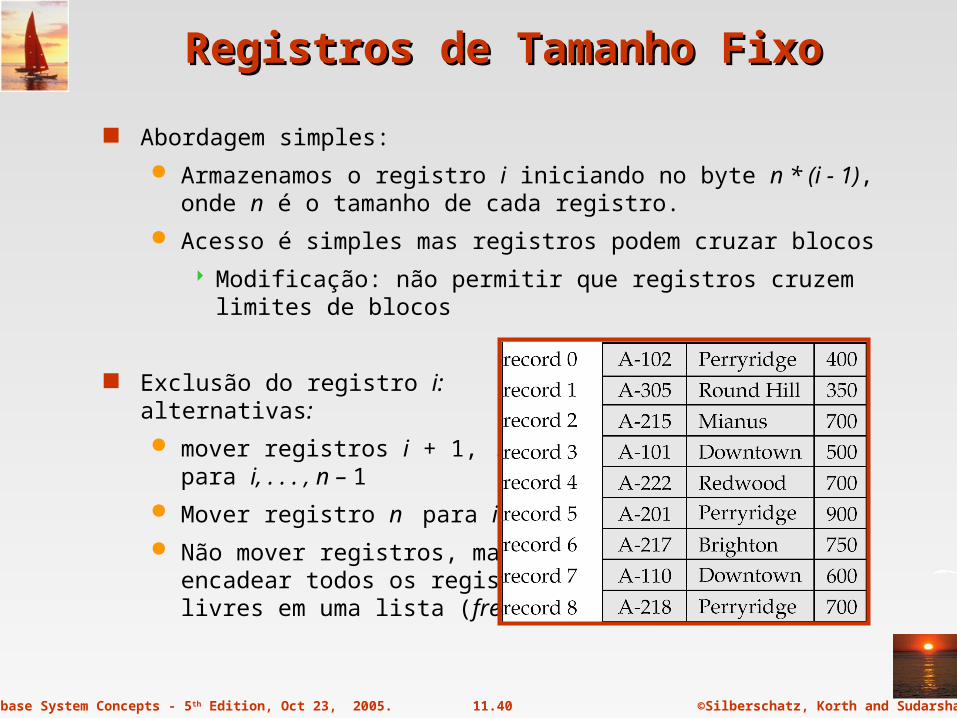
Abordagem simples:
Armazenamos o registro i iniciando no byte n * (i - 1), onde n é o tamanho de cada registro.
Acesso é simples mas registros podem cruzar blocos
Modificação: não permitir que registros cruzem limites de blocos
Exclusão do registro i: alternativas:
mover registros i + 1, . . ., n para i, . . . , n – 1
Mover registro n para i
Não mover registros, mas encadear todos os registroslivres em uma lista (free list)

©Silberschatz, Korth and Sudarshan11.41Database System Concepts - 5th Edition, Oct 23, 2005.
Listas Livres (Free Lists)Listas Livres (Free Lists)
Armazenar o endereço do primeiro registro excluído no cabeçalho
Usar o primeiro registro para armazenar o endereço do segundo registro e assim por diante
Pode-se pensar nestes endereços como ponteiros uma vez que “apontam” para a localização de um registro.
Representação mais eficiente: reutilizar espaço de atributos normais nos registros livres para armazenar ponteiros. (não armazenar ponteiros nos registros em uso)
©Silberschatz, Korth and Sudarshan11.42Database System Concepts - 5th Edition, Oct 23, 2005.
Registros de Comprimento VariávelRegistros de Comprimento Variável
Registros de comprimento variável surgem em sistemas de banco de dados de várias formas:
Armazenamento de múltiplos tipos de registros em um único arquivo.
Tipos de registros que permitem comprimento variável para um ou mais campos.
Tipos de registros que permitem campos repetitivos (usados em alguns modelos de dados).
©Silberschatz, Korth and Sudarshan11.43Database System Concepts - 5th Edition, Oct 23, 2005.
Registros Variáveis: Estrutura Slotted PageRegistros Variáveis: Estrutura Slotted Page
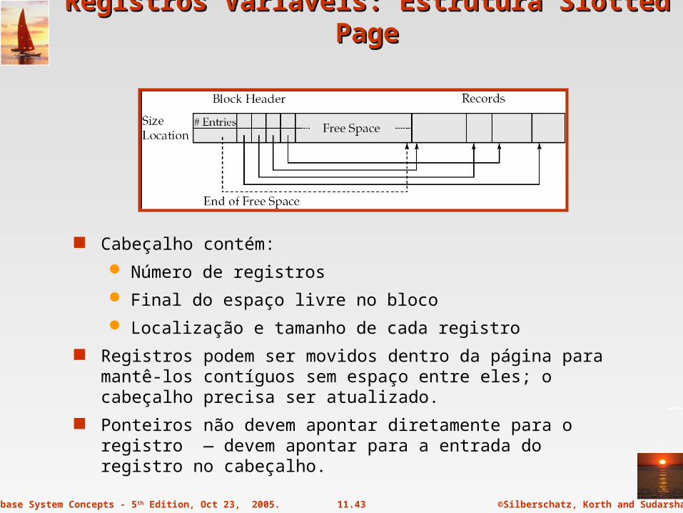
Cabeçalho contém:
Número de registros
Final do espaço livre no bloco
Localização e tamanho de cada registro
Registros podem ser movidos dentro da página para mantê-los contíguos sem espaço entre eles; o cabeçalho precisa ser atualizado.
Ponteiros não devem apontar diretamente para o registro — devem apontar para a entrada do registro no cabeçalho.
©Silberschatz, Korth and Sudarshan11.44Database System Concepts - 5th Edition, Oct 23, 2005.
Organização de Registros em ArquivosOrganização de Registros em Arquivos
Heap – um registro pode ser colocado em qualquer parte do arquivo em que haja espaço
Sequencial – armazena registros em ordem sequencial, baseado no valor da chave de busca de cada registro
Hashing – uma função de hash é calculada sobre algum atributo de cada registro; o resultado determina em qual bloco do arquivo o registro deve ser colocado
Registros de cada relação podem ser armazenados em arquivos separados. Em uma organização de arquivos multitabela registros de diferentes relações podem ser armazenados no mesmo arquivo
Motivação: armazenar registros no mesmo bloco para minimizar I/O
©Silberschatz, Korth and Sudarshan11.45Database System Concepts - 5th Edition, Oct 23, 2005.
Organização SequencialOrganização Sequencial
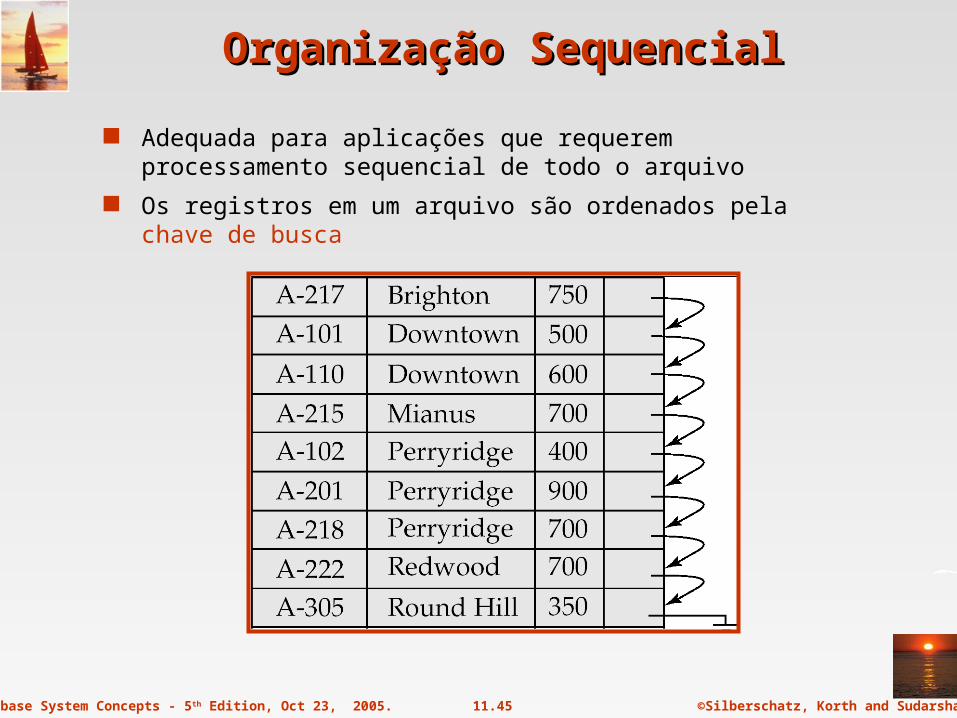
Adequada para aplicações que requerem processamento sequencial de todo o arquivo
Os registros em um arquivo são ordenados pela chave de busca
©Silberschatz, Korth and Sudarshan11.46Database System Concepts - 5th Edition, Oct 23, 2005.
Organização Sequencial (Cont.)Organização Sequencial (Cont.)
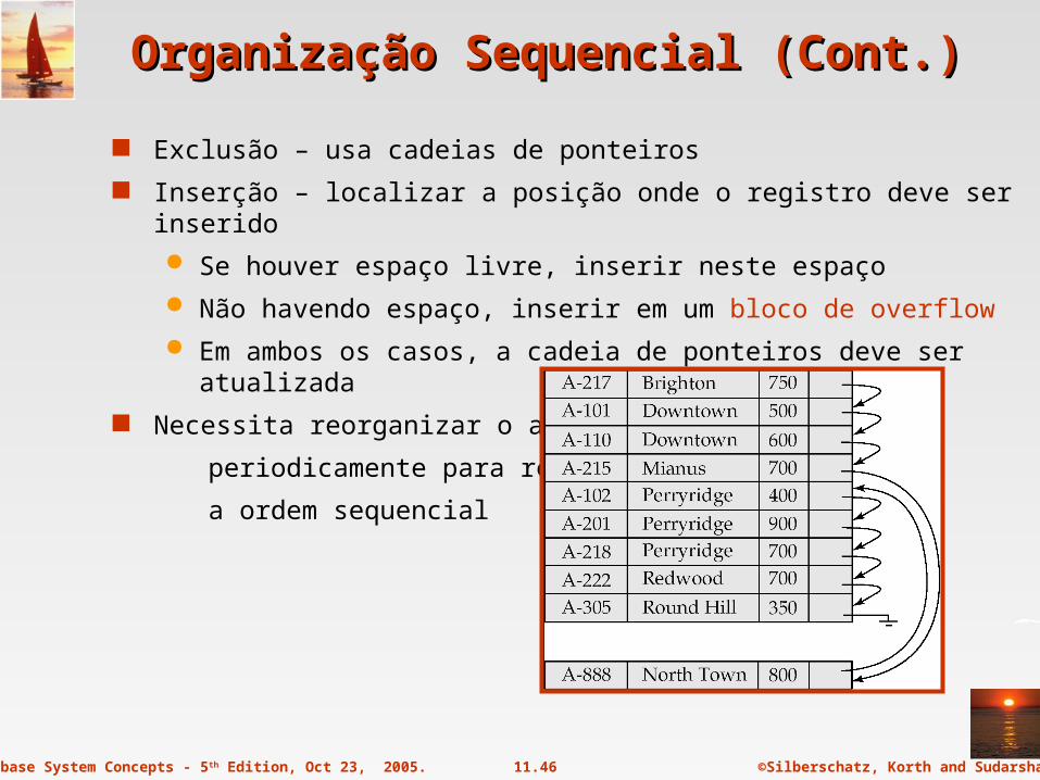
Exclusão – usa cadeias de ponteiros
Inserção – localizar a posição onde o registro deve ser inserido
Se houver espaço livre, inserir neste espaço
Não havendo espaço, inserir em um bloco de overflow
Em ambos os casos, a cadeia de ponteiros deve ser atualizada
Necessita reorganizar o arquivo
periodicamente para restaurar
a ordem sequencial

©Silberschatz, Korth and Sudarshan11.47Database System Concepts - 5th Edition, Oct 23, 2005.
Organização MultitabelaOrganização Multitabela
Armazenar várias relações em um único arquivo usando organização de arquivo em cluster multitabela

©Silberschatz, Korth and Sudarshan11.48Database System Concepts - 5th Edition, Oct 23, 2005.
Organização Multitabela (cont.)Organização Multitabela (cont.)
Organização em cluster multitabela de customer e depositor:
Bom para consultas envolvendo depositor customer, e para consultas envolvendo um único clente e suas contas
Ruim para consultas envolvendo somente cliente Resulta em registros de tamanho variável Pode-se adicionar cadeias de ponteiros para ligar registros de uma
relação específica

©Silberschatz, Korth and Sudarshan11.49Database System Concepts - 5th Edition, Oct 23, 2005.
Data Dictionary StorageData Dictionary Storage
Information about relations names of relations names and types of attributes of each relation names and definitions of views integrity constraints
User and accounting information, including passwords Statistical and descriptive data
number of tuples in each relation Physical file organization information
How relation is stored (sequential/hash/…) Physical location of relation
Information about indices (Chapter 12)
Data dictionary (also called system catalog) stores metadata; that is, data about data, such as

©Silberschatz, Korth and Sudarshan11.50Database System Concepts - 5th Edition, Oct 23, 2005.
Data Dictionary Storage (Cont.)Data Dictionary Storage (Cont.)
Catalog structure
Relational representation on disk
specialized data structures designed for efficient access, in memory
A possible catalog representation:
Relation_metadata = (relation_name, number_of_attributes, storage_organization, location)Attribute_metadata = (attribute_name, relation_name, domain_type,
position, length)User_metadata = (user_name, encrypted_password, group)Index_metadata = (index_name, relation_name, index_type,
index_attributes)View_metadata = (view_name, definition)
Database System Concepts, 5th Ed.
©Silberschatz, Korth and SudarshanSee www.db-book.com for conditions on re-use
End of Chapter 11End of Chapter 11
©Silberschatz, Korth and Sudarshan11.52Database System Concepts - 5th Edition, Oct 23, 2005.
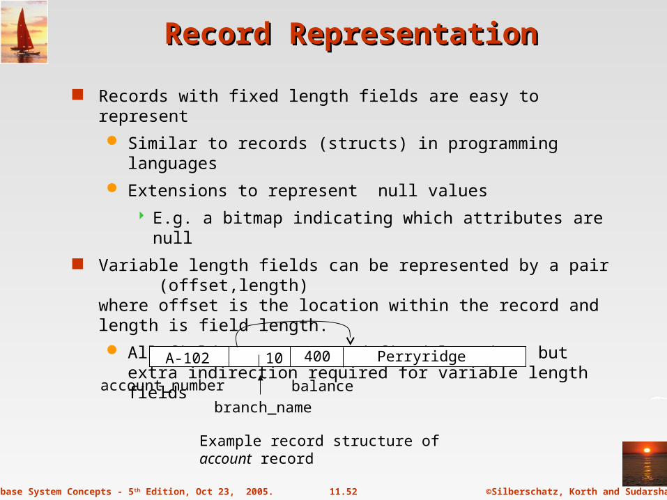
Record RepresentationRecord Representation
Records with fixed length fields are easy to represent
Similar to records (structs) in programming languages
Extensions to represent null values
E.g. a bitmap indicating which attributes are null
Variable length fields can be represented by a pair (offset,length) where offset is the location within the record and length is field length.
All fields start at predefined location, but extra indirection required for variable length fields
Example record structure of account record
account_number
branch_name
balance
PerryridgeA-102 40010

©Silberschatz, Korth and Sudarshan11.53Database System Concepts - 5th Edition, Oct 23, 2005.
File Containing File Containing account account Records Records
©Silberschatz, Korth and Sudarshan11.54Database System Concepts - 5th Edition, Oct 23, 2005.
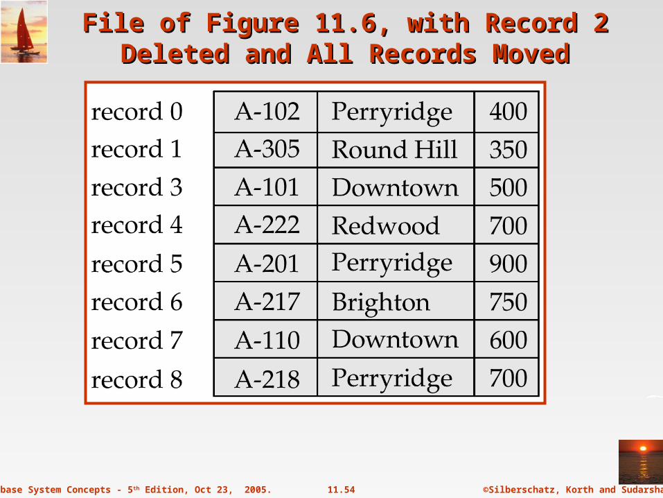
File of Figure 11.6, with Record 2 Deleted and File of Figure 11.6, with Record 2 Deleted and All Records MovedAll Records Moved
©Silberschatz, Korth and Sudarshan11.55Database System Concepts - 5th Edition, Oct 23, 2005.
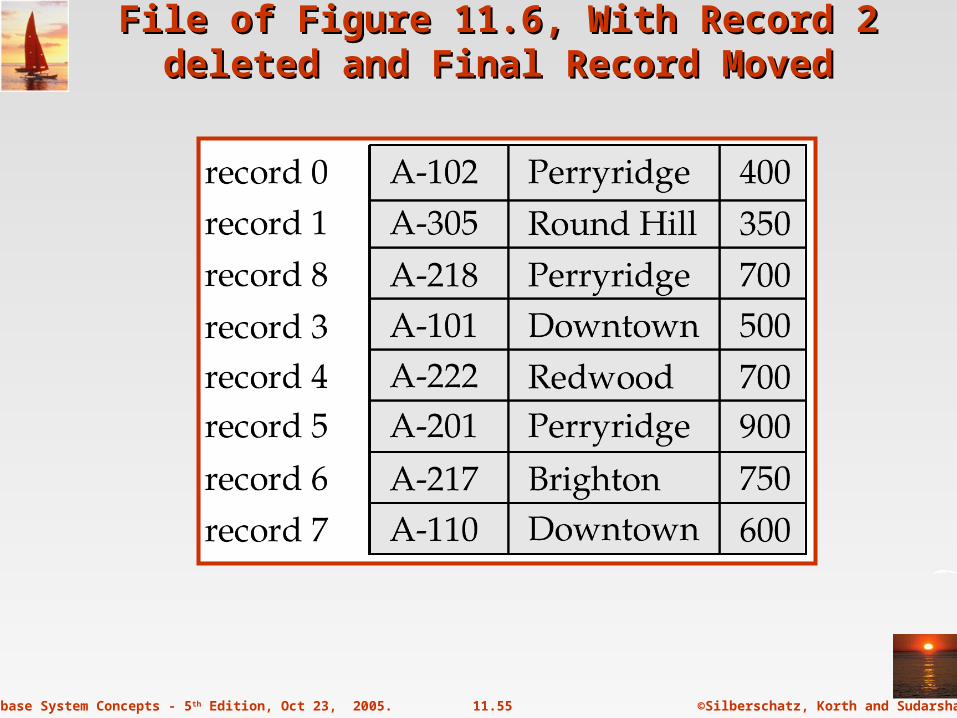
File of Figure 11.6, With Record 2 deleted and File of Figure 11.6, With Record 2 deleted and Final Record MovedFinal Record Moved
©Silberschatz, Korth and Sudarshan11.56Database System Concepts - 5th Edition, Oct 23, 2005.
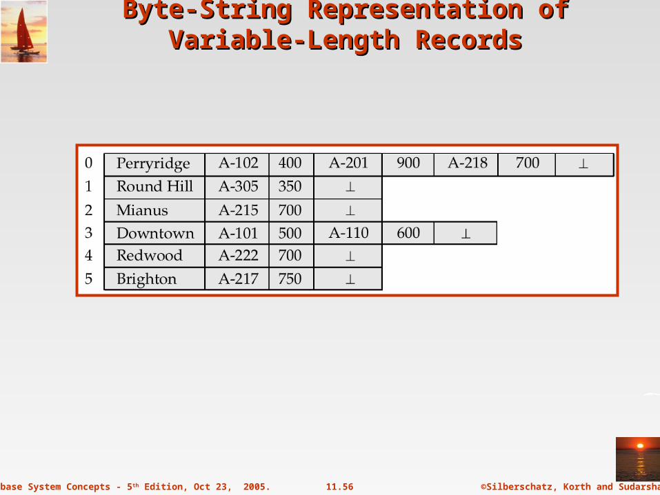
Byte-String Representation of Variable-Length Byte-String Representation of Variable-Length RecordsRecords
©Silberschatz, Korth and Sudarshan11.57Database System Concepts - 5th Edition, Oct 23, 2005.
Clustering File StructureClustering File Structure

©Silberschatz, Korth and Sudarshan11.58Database System Concepts - 5th Edition, Oct 23, 2005.
Clustering File Structure With Pointer ChainsClustering File Structure With Pointer Chains

©Silberschatz, Korth and Sudarshan11.59Database System Concepts - 5th Edition, Oct 23, 2005.
The The depositordepositor Relation Relation

©Silberschatz, Korth and Sudarshan11.60Database System Concepts - 5th Edition, Oct 23, 2005.
The The customer customer RelationRelation

©Silberschatz, Korth and Sudarshan11.61Database System Concepts - 5th Edition, Oct 23, 2005.
Clustering File StructureClustering File Structure

©Silberschatz, Korth and Sudarshan11.62Database System Concepts - 5th Edition, Oct 23, 2005.

©Silberschatz, Korth and Sudarshan11.63Database System Concepts - 5th Edition, Oct 23, 2005.
Figure 11.4Figure 11.4
©Silberschatz, Korth and Sudarshan11.64Database System Concepts - 5th Edition, Oct 23, 2005.
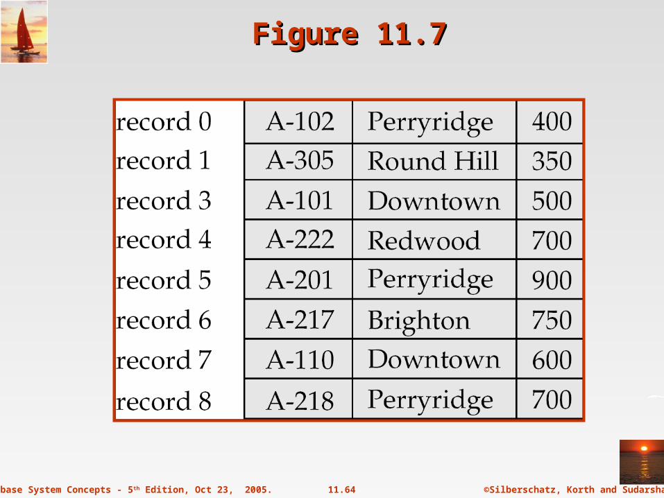
Figure 11.7Figure 11.7

©Silberschatz, Korth and Sudarshan11.65Database System Concepts - 5th Edition, Oct 23, 2005.
Figure 11.8Figure 11.8
©Silberschatz, Korth and Sudarshan11.66Database System Concepts - 5th Edition, Oct 23, 2005.
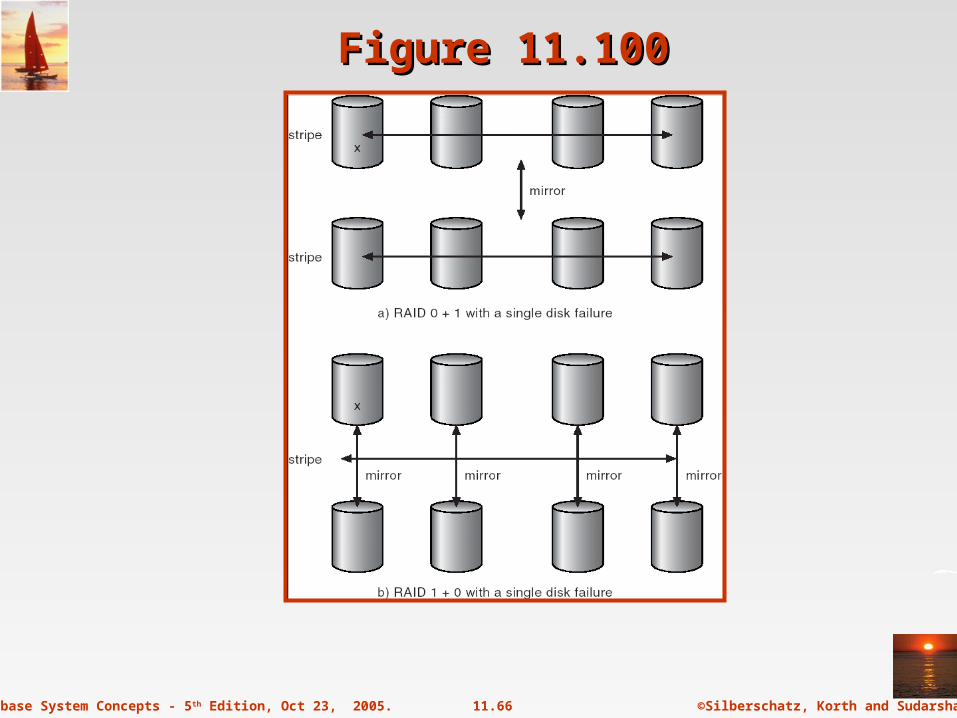
Figure 11.100Figure 11.100

©Silberschatz, Korth and Sudarshan11.67Database System Concepts - 5th Edition, Oct 23, 2005.
Figure 11.20Figure 11.20

©Silberschatz, Korth and Sudarshan11.68Database System Concepts - 5th Edition, Oct 23, 2005.
Byte-String Representation of Variable-Length RecordsByte-String Representation of Variable-Length Records
Byte string representationAttach an end-of-record () control character to the end of each recordDifficulty with deletionDifficulty with growth

©Silberschatz, Korth and Sudarshan11.69Database System Concepts - 5th Edition, Oct 23, 2005.
Fixed-Length RepresentationFixed-Length Representation
Use one or more fixed length records:
reserved space
pointers
Reserved space – can use fixed-length records of a known maximum length; unused space in shorter records filled with a null or end-of-record symbol.

©Silberschatz, Korth and Sudarshan11.70Database System Concepts - 5th Edition, Oct 23, 2005.
Pointer MethodPointer Method
Pointer method
A variable-length record is represented by a list of fixed-length records, chained together via pointers.
Can be used even if the maximum record length is not known
©Silberschatz, Korth and Sudarshan11.71Database System Concepts - 5th Edition, Oct 23, 2005.
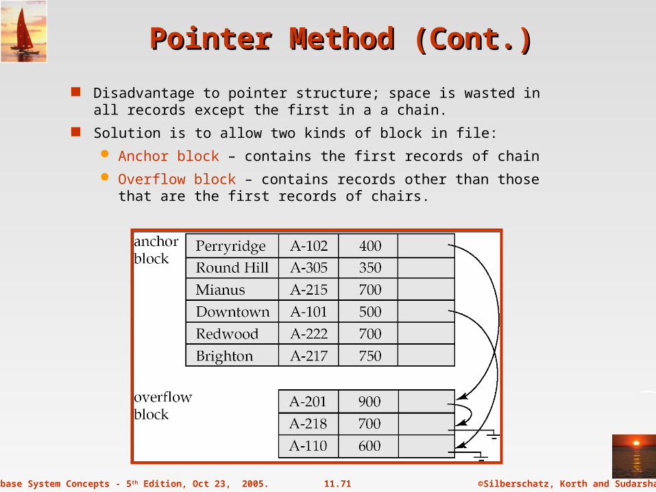
Pointer Method (Cont.)Pointer Method (Cont.)
Disadvantage to pointer structure; space is wasted in all records except the first in a a chain.
Solution is to allow two kinds of block in file:
Anchor block – contains the first records of chain
Overflow block – contains records other than those that are the first records of chairs.
©Silberschatz, Korth and Sudarshan11.72Database System Concepts - 5th Edition, Oct 23, 2005.
Mapping of Objects to FilesMapping of Objects to Files
Mapping objects to files is similar to mapping tuples to files in a relational system; object data can be stored using file structures.
Objects in O-O databases may lack uniformity and may be very large; such objects have to managed differently from records in a relational system.
Set fields with a small number of elements may be implemented using data structures such as linked lists.
Set fields with a larger number of elements may be implemented as separate relations in the database.
Set fields can also be eliminated at the storage level by normalization.
Similar to conversion of multivalued attributes of E-R diagrams to relations

©Silberschatz, Korth and Sudarshan11.73Database System Concepts - 5th Edition, Oct 23, 2005.
Mapping of Objects to Files (Cont.)Mapping of Objects to Files (Cont.)
Objects are identified by an object identifier (OID); the storage system needs a mechanism to locate an object given its OID (this action is called dereferencing).
logical identifiers do not directly specify an object’s physical location; must maintain an index that maps an OID to the object’s actual location.
physical identifiers encode the location of the object so the object can be found directly. Physical OIDs typically have the following parts:
1. a volume or file identifier
2. a page identifier within the volume or file
3. an offset within the page

©Silberschatz, Korth and Sudarshan11.74Database System Concepts - 5th Edition, Oct 23, 2005.
Management of Persistent PointersManagement of Persistent Pointers
Physical OIDs may be a unique identifier. This identifier is stored in the object also and is used to detect references via dangling pointers.
©Silberschatz, Korth and Sudarshan11.75Database System Concepts - 5th Edition, Oct 23, 2005.
Management of Persistent Pointers Management of Persistent Pointers (Cont.)(Cont.)
Implement persistent pointers using OIDs; persistent pointers are substantially longer than are in-memory pointers
Pointer swizzling cuts down on cost of locating persistent objects already in-memory.
Software swizzling (swizzling on pointer deference)
When a persistent pointer is first dereferenced, the pointer is swizzled (replaced by an in-memory pointer) after the object is located in memory.
Subsequent dereferences of of the same pointer become cheap.
The physical location of an object in memory must not change if swizzled pointers pont to it; the solution is to pin pages in memory
When an object is written back to disk, any swizzled pointers it contains need to be unswizzled.
©Silberschatz, Korth and Sudarshan11.76Database System Concepts - 5th Edition, Oct 23, 2005.
Hardware SwizzlingHardware Swizzling
With hardware swizzling, persistent pointers in objects need the same amount of space as in-memory pointers — extra storage external to the object is used to store rest of pointer information.
Uses virtual memory translation mechanism to efficiently and transparently convert between persistent pointers and in-memory pointers.
All persistent pointers in a page are swizzled when the page is first read in.
thus programmers have to work with just one type of pointer, i.e., in-memory pointer.
some of the swizzled pointers may point to virtual memory addresses that are currently not allocated any real memory (and do not contain valid data)
©Silberschatz, Korth and Sudarshan11.77Database System Concepts - 5th Edition, Oct 23, 2005.
Hardware SwizzlingHardware Swizzling
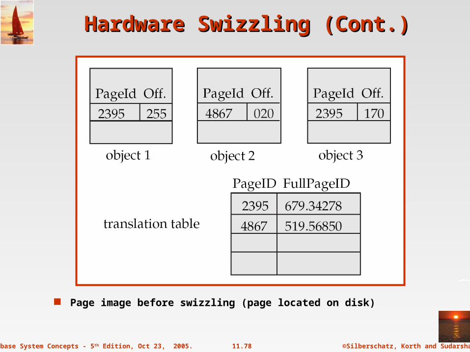
Persistent pointer is conceptually split into two parts: a page identifier, and an offset within the page.
The page identifier in a pointer is a short indirect pointer: Each page has a translation table that provides a mapping from the short page identifiers to full database page identifiers.
Translation table for a page is small (at most 1024 pointers in a 4096 byte page with 4 byte pointer)
Multiple pointers in page to the same page share same entry in the translation table.
©Silberschatz, Korth and Sudarshan11.78Database System Concepts - 5th Edition, Oct 23, 2005.
Hardware Swizzling (Cont.)Hardware Swizzling (Cont.)
Page image before swizzling (page located on disk)

©Silberschatz, Korth and Sudarshan11.79Database System Concepts - 5th Edition, Oct 23, 2005.
Hardware Swizzling (Cont.)Hardware Swizzling (Cont.)
When system loads a page into memory the persistent pointers in the page are swizzled as described below
1. Persistent pointers in each object in the page are located using object type information
2. For each persistent pointer (pi, oi) find its full page ID Pi
1. If Pi does not already have a virtual memory page allocated to it,
allocate a virtual memory page to Pi and read-protect the page
Note: there need not be any physical space (whether in memory or on disk swap-space) allocated for the virtual memory page at this point. Space can be allocated later if (and when) Pi is accessed. In this case read-protection is not required.
Accessing a memory location in the page in the will result in a segmentation violation, which is handled as described later
2. Let vi be the virtual page allocated to Pi (either earlier or above)
3. Replace (pi, oi) by (vi, oi)
3. Replace each entry (pi, Pi) in the translation table, by (vi, Pi)
©Silberschatz, Korth and Sudarshan11.80Database System Concepts - 5th Edition, Oct 23, 2005.
Hardware Swizzling (Cont.)Hardware Swizzling (Cont.)
When an in-memory pointer is dereferenced, if the operating system detects the page it points to has not yet been allocated storage, or is read-protected, a segmentation violation occurs.
The mmap() call in Unix is used to specify a function to be invoked on segmentation violation
The function does the following when it is invoked
1. Allocate storage (swap-space) for the page containing the referenced address, if storage has not been allocated earlier. Turn off read-protection
2. Read in the page from disk
3. Perform pointer swizzling for each persistent pointer in the page, as described earlier

©Silberschatz, Korth and Sudarshan11.81Database System Concepts - 5th Edition, Oct 23, 2005.
Hardware Swizzling (Cont.)Hardware Swizzling (Cont.)
Page with short page identifier 2395 was allocated address 5001. Observe change in pointers and translation table.
Page with short page identifier 4867 has been allocated address 4867. No change in pointer and translation table.
Page image after swizzling

©Silberschatz, Korth and Sudarshan11.82Database System Concepts - 5th Edition, Oct 23, 2005.
Hardware Swizzling (Cont.)Hardware Swizzling (Cont.)
After swizzling, all short page identifiers point to virtual memory addresses allocated for the corresponding pages
functions accessing the objects are not even aware that it has persistent pointers, and do not need to be changed in any way!
can reuse existing code and libraries that use in-memory pointers
After this, the pointer dereference that triggered the swizzling can continue
Optimizations:
If all pages are allocated the same address as in the short page identifier, no changes required in the page!
No need for deswizzling — swizzled page can be saved as-is to disk
A set of pages (segment) can share one translation table. Pages can still be swizzled as and when fetched (old copy of translation table is needed).
A process should not access more pages than size of virtual memory — reuse of virtual memory addresses for other pages is expensive

©Silberschatz, Korth and Sudarshan11.83Database System Concepts - 5th Edition, Oct 23, 2005.
Disk versus Memory Structure of ObjectsDisk versus Memory Structure of Objects
The format in which objects are stored in memory may be different from the formal in which they are stored on disk in the database. Reasons are:
software swizzling – structure of persistent and in-memory pointers are different
database accessible from different machines, with different data representations
Make the physical representation of objects in the database independent of the machine and the compiler.
Can transparently convert from disk representation to form required on the specific machine, language, and compiler, when the object (or page) is brought into memory.
©Silberschatz, Korth and Sudarshan11.84Database System Concepts - 5th Edition, Oct 23, 2005.
Large ObjectsLarge Objects
Large objects : binary large objects (blobs) and character large objects (clobs)
Examples include:
text documents
graphical data such as images and computer aided designs audio and video data
Large objects may need to be stored in a contiguous sequence of bytes when brought into memory.
If an object is bigger than a page, contiguous pages of the buffer pool must be allocated to store it.
May be preferable to disallow direct access to data, and only allow access through a file-system-like API, to remove need for contiguous storage.

©Silberschatz, Korth and Sudarshan11.85Database System Concepts - 5th Edition, Oct 23, 2005.
Modifying Large ObjectsModifying Large Objects
If the application requires insert/delete of bytes from specified regions of an object:
B+-tree file organization (described later in Chapter 12) can be modified to represent large objects
Each leaf page of the tree stores between half and 1 page worth of data from the object
Special-purpose application programs outside the database are used to manipulate large objects:
Text data treated as a byte string manipulated by editors and formatters.
Graphical data and audio/video data is typically created and displayed by separate application
checkout/checkin method for concurrency control and creation of versions
Top Related