WiNeS - A Flexible Framework for Wireless Network ... · documento descreve a arquitetura do WiNeS...
27
PONTIFÍCIA UNIVERSIDADE CATÓLICA DO RIO GRANDE DO SUL FACULDADE DE INFORMÁTICA PROGRAMA DE PÓS-GRADUAÇÃO EM CIÊNCIA DA COMPUTAÇÃO WiNeS - A Flexible Framework for Wireless Network Description and Simulation Vinicius Bohrer, Ramon Fernandes, Thais Webber, César Marcon Technical Report Nº 070 Porto Alegre, Dezembro de 2012
Transcript of WiNeS - A Flexible Framework for Wireless Network ... · documento descreve a arquitetura do WiNeS...
PONTIFÍCIA UNIVERSIDADE CATÓLICA DO RIO GRANDE DO SUL
FACULDADE DE INFORMÁTICA PROGRAMA DE PÓS-GRADUAÇÃO EM CIÊNCIA DA COMPUTAÇÃO
WiNeS - A Flexible Framework for
Wireless Network Description and Simulation
Vinicius Bohrer, Ramon Fernandes, Thais Webber, César Marcon
Technical Report Nº 070
Porto Alegre, Dezembro de 2012

WINES - A FLEXIBLE FRAMEWORK FOR WIRELESS NETWORK
DESCRIPTION AND SIMULATION
RESUMO
Há um número crescente de sistemas operando com redes sem fios, devido à elevada
flexibilidade de implantação. No entanto, as redes sem fio são mais sensíveis às
mudanças ambientais do que as redes com fio implicando em projetos mais complexos.
Para reduzir o tempo de projeto, normalmente, os projetistas dependem de técnicas de
simulação para uma descrição de rede de alto nível e uma avaliação de desempenho
confiável. Assim, as ferramentas de apoio devem fornecer recursos úteis para descrever
facilmente protocolos de comunicação, bem como proporcionar estimativas precisas. Este
documento descreve a arquitetura do WiNeS (Simulador de rede sem fio), que é uma
estrutura projetada para simular dispositivos de rede, homogêneos e heterogêneos, como
também simular interconexões. WiNeS foi desenvolvido para ser o mais flexível possível
para acomodar diversos requisitos de simulação. Distância máxima de comunicação para
determinados dispositivos em simulações 2D/3D, eventos programados para os
dispositivos baseados no relógio interno do simulador, e as regras de pareamento para
definir quais os dispositivos são capazes de estabelecer comunicação entre si, esses são
exemplos de parâmetros configuráveis. As Avaliações dos cenários de teste demonstram
que o framework WiNeS é realmente capaz de simular ambientes de rede sem fio e
suporta diversas customizações de dispositivos sem fio.
Palavras-chave: Redes Sem Fio, Redes Ponto-a-Ponto, RSSF, Simulação.
WINES - A FLEXIBLE FRAMEWORK FOR WIRELESS NETWORK
DESCRIPTION AND SIMULATION
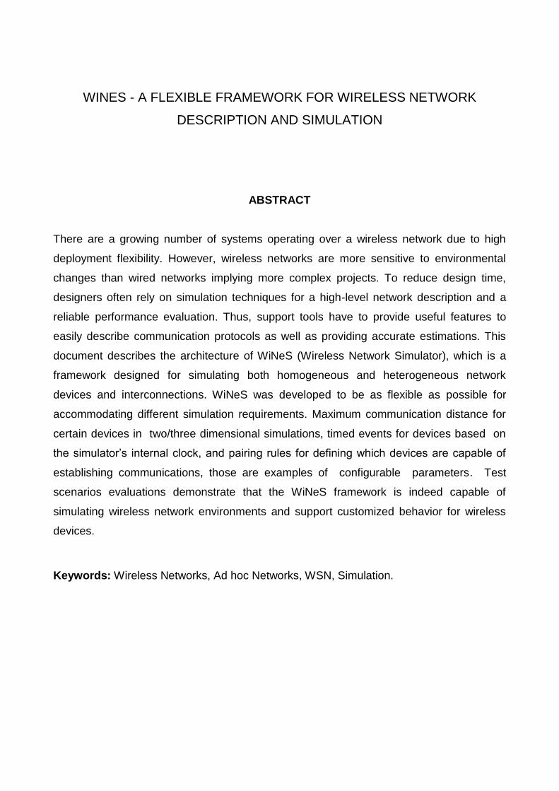
ABSTRACT
There are a growing number of systems operating over a wireless network due to high
deployment flexibility. However, wireless networks are more sensitive to environmental
changes than wired networks implying more complex projects. To reduce design time,
designers often rely on simulation techniques for a high-level network description and a
reliable performance evaluation. Thus, support tools have to provide useful features to
easily describe communication protocols as well as providing accurate estimations. This
document describes the architecture of WiNeS (Wireless Network Simulator), which is a
framework designed for simulating both homogeneous and heterogeneous network
devices and interconnections. WiNeS was developed to be as flexible as possible for
accommodating different simulation requirements. Maximum communication distance for
certain devices in two/three dimensional simulations, timed events for devices based on
the simulator’s internal clock, and pairing rules for defining which devices are capable of
establishing communications, those are examples of configurable parameters. Test
scenarios evaluations demonstrate that the WiNeS framework is indeed capable of
simulating wireless network environments and support customized behavior for wireless
devices.
Keywords: Wireless Networks, Ad hoc Networks, WSN, Simulation.

Summary
1 Introduction .......................................................................................................... 5
2 WiNeS Framework .............................................................................................. 7
2.1 Architecture ................................................................................................... 8
2.1.1 Definitions Block ...................................................................................... 8
2.1.2 Application layer ...................................................................................... 9
2.1.3 Core ....................................................................................................... 11
2.2 Communication ........................................................................................... 12
2.2.1 Message Protocol .................................................................................. 12
2.2.2 Global clock ........................................................................................... 13
2.2.3 Operation ............................................................................................... 14
2.2.4 Comparing Engine ................................................................................. 15
3 Modeling examples............................................................................................ 16
3.1 WSN with Heterogeneous Topology ........................................................... 16
3.2 Heterogeneous Star Topology .................................................................... 17
4 Related Work ..................................................................................................... 20
4.1 Castalia ....................................................................................................... 20
4.2 SENS – Sensor, Environment, Network Simulator ..................................... 20
4.3 GloMoSim ................................................................................................... 21
4.4 OPNET ....................................................................................................... 21
4.5 NS-2 ............................................................................................................ 22
4.6 NS-3 ............................................................................................................ 22
4.7 OMNeT++ ................................................................................................... 23
4.8 Overview ..................................................................................................... 23
5 CONCLUSION .................................................................................................. 25
6 REFERENCES .................................................................................................. 26

5
1 INTRODUCTION
Nowadays, there have been many proposals of wireless networks for joining several
protocols on the same network, such as Bluetooth [1], Wi-Fi [2], and Zigbee [3]. These
networks use different frequencies and communication protocols, forming multiprotocol
systems to meet a greater range of applications.
However, in this context several problems arise, such as how to choose the best
node positioning in the environment for ensuring the correct pairing of different devices,
and how to know the most efficient type of device to perform a given communication. Such
issues demand alternatives to evaluate varied scenarios before systems’ deployment.
Many open source network simulators are currently available like J-Sim [4], NS-2 [5], NS-3
[6], OMNet++ [7], SSFNet [8] and Castalia [9], and commercial ones such as OPNET [10]
and QualNet [11]. All simulators present advantages and drawbacks related to their
architectures, features and applicability, mainly the fact that they are platform dependent
and some have issues related to scalability and end user facilities [9][11][12][13].
The Wireless Network Simulator (WiNeS) is proposed as a platform independent
framework written entirely in Java programming language. It supports discrete event (DE),
synchronous reactive (SR) and asynchronous reactive (ASR) models of simulation for
wireless networks. The WiNeS goal is to provide a flexible simulation environment to
accommodate any sort of wireless network topology, communication protocols, and device
types, while remaining simple enough for the end user to implement such features without
a deep understanding of the underlying simulator architecture and operations. Additionally,
the simulation engine is constructed to be as lean as possible to allow nodes scalability.
WiNeS framework employs sockets as message exchanging mechanism, allowing
the transmission of any sort of data between simulated devices. A set of predefined
simulation rules ascertains if one device is capable of communicating with another one.
Furthermore, even if a set of devices is incapable of establishing communications based
on a lack of a specific rule, it is possible that another set of rules exists to satisfy the
communication requirements for the involved devices. Additionally, the framework
supports heterogeneous devices, providing multiple communication capabilities for a
single node.
This technical report is organized as follows. Section 2 describes the WiNeS
framework in detail. Section 3 describes the framework capabilities and features,

6
instantiating two simulation scenarios. Section 4 presents the similar tools. Finally, in
Section 5 conclude the work contribution with discussions about WiNeS future
improvements.

7
2 WINES FRAMEWORK
The WiNeS framework is composed of several features such as: (i) checking for the
communication possibility between nodes; (ii) simulation of different network topologies;
(iii) simulation of homogeneous and heterogeneous architectures; and (iv) simulation of
user implemented protocols.
The framework is intended to be generic enough to support a wide range of
complexity on topology/architecture/communication, depending on the end user
implementation, while guaranteeing the correct enforcement of communication rules
between nodes, i.e. based on protocols, frequencies and geographic locations. WiNeS is
not designed to be aware of any details pertaining protocols or device types, thus any type
of additional information required for network operations is provided by external libraries or
should be developed by the designer.
As illustrated in Figure 1, WiNeS presents an environment for complete simulation
of wireless networks. The communication infrastructure implemented between
components is TCP/IP sockets. Each information sent from a node to another one passes
through an Environment emulation component, which checks the devices communicability.
User defined nodes
Default nodes
Abstract node layer
Communication infraestructure Environment emulation
Extends
WiNeSApplication
Figure 1 – Software layers of WiNeS framework.
WiNeS framework presents an abstraction layer for node’s behavior description,
which enables to add several functionalities (e.g. protocols). Additionally, WiNeS provides
a standard node behavior based on predefined parameters, which is a discrete event
model for generating network traffic as follows.

8
2.1 Architecture
The WiNeS framework architecture is divided in three parts, as illustrated in Figure
2: (i) Definitions block; (ii) Application layer; and (iii) Core.
DefinitionsCore
Application. . .
Node 2 WiNeS
Node 1Node n
Figure 2 – Main components of the WiNeS framework.
2.1.1 Definitions Block
The definitions block is composed of a series of simulation rules containing
characteristics of wireless technologies, e.g. total simulation time, parity rules for defining if
a given device A is capable of communicating with another device B. It also contains
general information such as simulation time, distance, and time scales in a wide variety of
known units.
<CONNECTIVITY_RULES> <RULE frequency="2.4GHz" typeDevice1="antenna" typeDevice2="antenna" distance="100"/> <RULE frequency="2.4GHz" typeDevice1="antenna" typeDevice2="WSN" distance="20"/> </CONNECTIVITY_RULES> <TIME_SCALE> <UNITY unity="seconds"/> <VALUE value="30"/> </TIME_SCALE> <SIMULATION_TIME>20</SIMULATION_TIME> <DISTANCE_SCALE> <UNITY unity="km"/> <VALUE value="3"/> </DISTANCE_SCALE>
Figure 3 - Example of a XML input file for definitions block.
Definition parameters can be provided to WiNeS either on a XML file or on a Java
description file using the simulator’s Java API. Figure 3 illustrates an example of definition
block described on a XML file that contains the following tags: (i) Connectivity Rules:
composed of rules specified by the designer for each pairing between two device types.
Each rule describes the maximum distance that a node can communicate with another
based on their frequencies; (ii) Time Scale: where the user indicates how often the

9
simulator should increase a unit of simulation time, e.g. at every 30 seconds the total
simulation time should be incremented by one time unit; (iii) Simulation Time: indicates the
amount of time units for the simulation run, e.g. the simulation time is set to 20x30 = 600
seconds; (iv) Distance Scale: indicates the real distance that each simulation unit
represents.
2.1.2 Application layer
The application layer is composed by nodes that can only communicate via sockets
with the Core. Nodes are created from information provided in a XML file, or from API
methods. When a node is created, the designer can specify a customized application
layer, thus eliminating the need of the predefined table of behaviors. However, it is still
possible to rely on the events defined in this table, if needed.
Figure 4 illustrates an example of XML file for mapping a heterogeneous node with
temperature and humidity sensors integrated with an RFID active tag. This node is located
at position (3, 5, 8), type non-passive. It has two antennas for transmission and reception.
Its sensor part uses Zigbee protocol at a frequency of 2.4 GHz for communication, while its
RFID part uses EPC Gen2 protocol at 5 GHz.
<NODE> <NODE_INFO> <POSITION X="3.0" Y="5.5" Z="8.0"/> <TYPE nodeType="0"/></NODE_INFO> <COMPONENT_SPECIFICATION> <TYPE typeDevice="sensor"/> <OPERATION protocol="ZigBee"freq="2.4GHz" power="1.3"/> </COMPONENT_SPECIFICATION> <COMPONENT_SPECIFICATION> <TYPE typeDevice="activeTag"/> <OPERATION protocol="EPC Gen2"freq="5GHz" power="1"/> </COMPONENT_SPECIFICATION> <BEHAVIOR_SPECIFICATION> <TEMPERATURE time="0" value="12.8"/> <TEMPERATURE time="125" value="10.92"/> <HUMIDITY time="0" value="23.8"/> <HUMIDITY time="25" value="24.9"/> </BEHAVIOR_SPECIFICATION> </NODE>
Figure 4–Example of RFID active tag description.
Basically, nodes are mapped on two tables: (i) Specification Table: component
recognized by the tags <NODE_INFO>and<COMPONENT_SPECIFICATION>. This table
contains data referring to the node general characteristics (e.g. protocol, frequency and
position), representing its communication capabilities. Remark that the node specification
can have more than one specification tag, demonstrating that it is a heterogeneous device;

10
and (ii) Behavior Table: component recognized by the tag
<BEHAVIOR_SPECIFICATION>. This table contains data related to the node behavior
establishing a relationship with the simulation time units. Here, a node may express all
instants in which a given parameter changes with a discrete event list that may perform
network traffic.
The nodeType information, from tag <NODE_INFO>, is used to indicate if the node
is passive ('1') or non-passive ('0'). If a node is of type non-passive (e.g. passive RFID
tags), it has no autonomy to initiate communication with another node, and it only
responds to stimuli originated from other nodes, if applicable.
The node architecture is illustrated on
Figure 5, where (i) dashed arrows indicate read access; (ii) dotted arrows illustrate
messages exchange between node and Core; and (iii) continuous arrows indicate the
processing flow in the simulation.
Client Socket Thread Server Socket Thread
Specifications Table
Core
Global Clock
Processing
Application Layer Behavior TableNode n
WiNeS
Node 1
Node 2
...
Definitions
Figure 5–Node architecture.
Each node has a unique address on the network, consisting of IP and port. At first
time, each node sends a packet to the simulation Core, requesting its inclusion. The Core
then creates a new entry on the Connections Table and stores this new node’s IP address
and port number, along with other relevant data provided by the node at connection time.
After being registered on the simulator’s Connection Table, the node becomes “visible” to
other nodes, and capable of exchanging data on the simulation environment.
The node’s operation depends on the designer implementation. If a customized
application layer is defined for a given node, then this node will behave accordingly;
otherwise the node will rely on two default behavior patterns:(i) when there is a current-

11
time behavior - the node checks its behavior table to verify if it has some data to be sent to
the simulation environment, based on the current simulation time;(ii) when the simulation
Core forwards data to a node from another node – each time, a node may communicate
with others by sending requests to a specific IP address and port number.
The application layer implemented by the designer may be coupled to the default
processing system within the node. The framework should provide an API with node
functions enabling this layer to receive and to send packets to other nodes. Therefore, with
this layer, the node may assume the processing implemented by the designer, which can
be used for simulating protocols, network topologies, packet loss, or any other desired
functionality, and even rely on predefined behaviors described on the node’s Behavior
Table for generating network traffic.
2.1.3 Core
The Core performs all computational logic to perform the communications between
nodes. As illustrated in Figure 6, the Core architecture is composed of (i) a thread for
receiving data from the nodes (Server Socket Thread); (ii) a set of threads (Processing
Threads) that process all received packets and determine to which nodes the data should
be forwarded to, while generating event logs; (iii) a thread for sending data to the nodes
(Client Socket Thread); and (iv) a Connections Table that composed of information about
the simulated nodes. Additionally, the Core automatically assigns a port number for the
nodes if it is not previously specified.
WiNeSApplication
. . .Node 2
Node 1
Node n
Core
Server Socket Thread Client Socket Thread
Definitions
Connections Table
Comparing engine
Event queueProcessing Threads
Global Clock
Figure 6 –Core architecture.
Server Socket Thread waits for messages sent from application nodes. If the Core
receives a request message from a new node to enter into the network, it should (i) verify if

12
the information is valid and interpretable, (ii) add the node in the Connections table and (iii)
response if the negotiation was successful or not. If the Core receives any other type of
message, the message is inserted into an event queue to be consumed by the Processing
Threads.
The Processing Threads should get the first element of event queue, if any, and
send it to the Comparing engine, where occurs the decision for which nodes that message
in the event queue will be forwarded to.
The Connections Table comprises a list of nodes, each node containing: (i) NodeID:
unique identifier generated by the Core; (ii) IpAddress: TCP/IP address on the network; (iii)
PortNum: TCP port on the network; (iv) Parameters: list of characteristics of the node
according to tag <COMPONENT_SPECIFICATION> of Figure 4; (v) Timeslot: a variable
that stores the clock time value received from last packet of the corresponding node. This
value is used to control time difference between consecutive packets; (vi) Coordinates: X,
Y and Z geographic positions of the node.
2.2 Communication
This section details the messages traffic within the simulation environment. For
instance, nodes request to enter the simulation, the logic of the global simulation clock,
and mostly how the Core processes a message forwarding from one node to another in
accordance with the Definitions block.
2.2.1 Message Protocol
The package format defined by the WiNeS communication protocol consists of five
fields: packet type, device type, nodeID, timeslot, and payload.
The packet type field specifies the nature of the message: (i) ENTRY_REQUEST is
used when a node requires entering in the simulation; (ii) ENTRY_ANSWER is used when
the Core responds to an ENTRY_REQUEST message; (iii) EXIT_REQUEST is used when
a node wants to leave the simulation. The use of ENTRY_REQUEST and
EXIT_REQUEST enables the dynamicity of insert and remove nodes from simulation
environment; (iv) SEND_DATA is used for all elements of WiNeS, sending generic data;
(v) END_SIMULATION is used by the Core to inform the nodes that simulation is
terminated. As consequence, all computation resources are released.
13
The device type field indicates the type of the element that is originating the packet.
There are two types of information: (i) CORE - when the simulation Core is creating the
package; and (ii) LOGICAL_NODE - when a node is creating the package.
The NodeID field informs the identification of the element that is sending the packet.
If it is the Core, this field is set to zero; otherwise this field is set to NodeID, which is the
identification number of the node that originated the packet.
The timeslot field contains the time when the packet was generated, which is
obtained from the global simulation clock.
The payload is a generic field used to carry any kind of data originated from the
given device type and related packet type. The payload format should respect the
following rules to each packet type: (i) ENTRY_REQUEST - node must send a TCP port
(zero if none), its specification table, and its coordinates; (ii) ENTRY_ANSWER - Core
must confirm the requested port number from the node, or send the automatically
generated port number and NodeID; (iii) EXIT_REQUEST - the node must send its
NodeID to the Core then it can remove the specified node from the Connections table; (iv)
SEND_DATA – a generic payload that depends on the device type field.
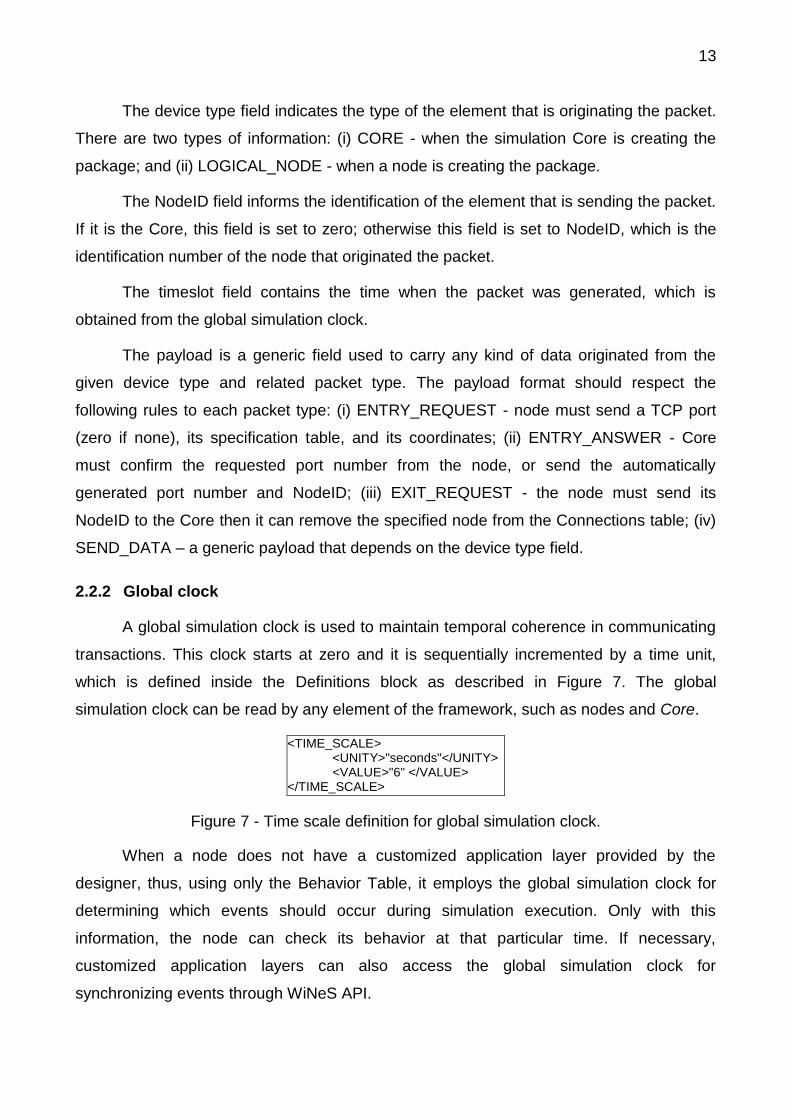
2.2.2 Global clock
A global simulation clock is used to maintain temporal coherence in communicating
transactions. This clock starts at zero and it is sequentially incremented by a time unit,
which is defined inside the Definitions block as described in Figure 7. The global
simulation clock can be read by any element of the framework, such as nodes and Core.
<TIME_SCALE> <UNITY>"seconds"</UNITY> <VALUE>"6" </VALUE> </TIME_SCALE>
Figure 7 - Time scale definition for global simulation clock.
When a node does not have a customized application layer provided by the
designer, thus, using only the Behavior Table, it employs the global simulation clock for
determining which events should occur during simulation execution. Only with this
information, the node can check its behavior at that particular time. If necessary,
customized application layers can also access the global simulation clock for
synchronizing events through WiNeS API.

14
2.2.3 Operation
When simulation starts, a mapping of all devices specifications occurs either from
the supplied XML definitions file or through the parsed information originated from the API.
Each device is then instantiated as a node based on these definitions, and registered on
the Connections Table of the Core. The Connections Table assigns a specific port number
for each registered node for later communications (a heterogeneous node is recognized as
a single node by the simulation engine). These activities, along with other events that
occur during simulation execution, are logged into text files for later analyzing. The
Connections Table also stores additional information about each connected node such as
operating frequencies, protocols and geographical coordinates. The information is used by
the Core to determine possible communications between simulated nodes. The basic
simulation flow is described by the message chart diagram in Figure 8.
Resources release
InitializationNode B resource allocation...
Release Node A resources
Core
Resources release
Initialization
Node A resource allocationNodeID and TCP creationAdd A in Connec. Table
Initialization procedure
Op
erat
ing
...
Node A
ENTRY_REQUEST
ENTRY_ANSWER
SEND_DATA
SEND_DATA
SEND_DATA
EXIT_REQUEST
Op
erat
ing
...
Node B
ENTRY_REQUEST
ENTRY_ANSWER
Star
tin
g
Star
tin
g
SEND_DATA
SEND_DATA
EXIT_REQUEST (end simulation)
Release all resources
Op
erat
ing
...
Figure 8 – Message chart diagram for the Core operation.
When a device is intended to join the network, it should send to the Core an
ENTRY_REQUEST message with its Specifications Table. After wards the node waits for
an ENTRY_ANSWER response from the Core. Meanwhile, the Core allocates resources
for node communication, generates a unique NodeID and updates the Connections Table.
Then, the Core sends the response to the node, with an ENTRY_ANSWER message,
informing the attributed NodeID and TCP port number and the node is able to send and
receive messages.
15
At any time, the Core is awaiting data. When any packet is received by Core, with
the exception of ENTRY_REQUEST, the packet is queued in the Event queue to be
consumed by the Processing Threads (please refer to Figure 6).
Parallel to any procedure, the Core always checks if the Event queue is not empty.
If there is any event to be processed, the Core removes the event from the queue, and
processes it in the Comparing engine.
During simulation, the Core generates a log of every transaction. After the
simulation time completion (stipulated by the designer), the Core generates a final log
entry with general statistics, e.g. the total amount of data exchanged throughout the
simulation.
2.2.4 Comparing Engine
The Event queue contains all SEND_DATA messages originated from the nodes.
The Comparing engine consumes and analyses one message at a time, defining which
node has the technological capacity (i.e. devices with compatible frequencies and
protocols) and geographic capacity (i.e. devices in reachable X, Y and Z coordinates) to
receive each message. The Comparing engine, being aware of this message, processes
the following steps: (i) unpack the SEND_DATA message to recognize the NodeID, the
global clock value, and payload; (ii) from NodeID, find this corresponding node (e.g. N1) in
the Connections Table and get its component specification data; (iii) look at all the nodes
in the Connections Table. For each different node in the table (e.g. N2), the engine
compares the component specifications with N1 and evaluate if both nodes are within
communication range. For each successful comparison, the Core generates a packet with
the same payload received from N1, forwarding the message to N2.
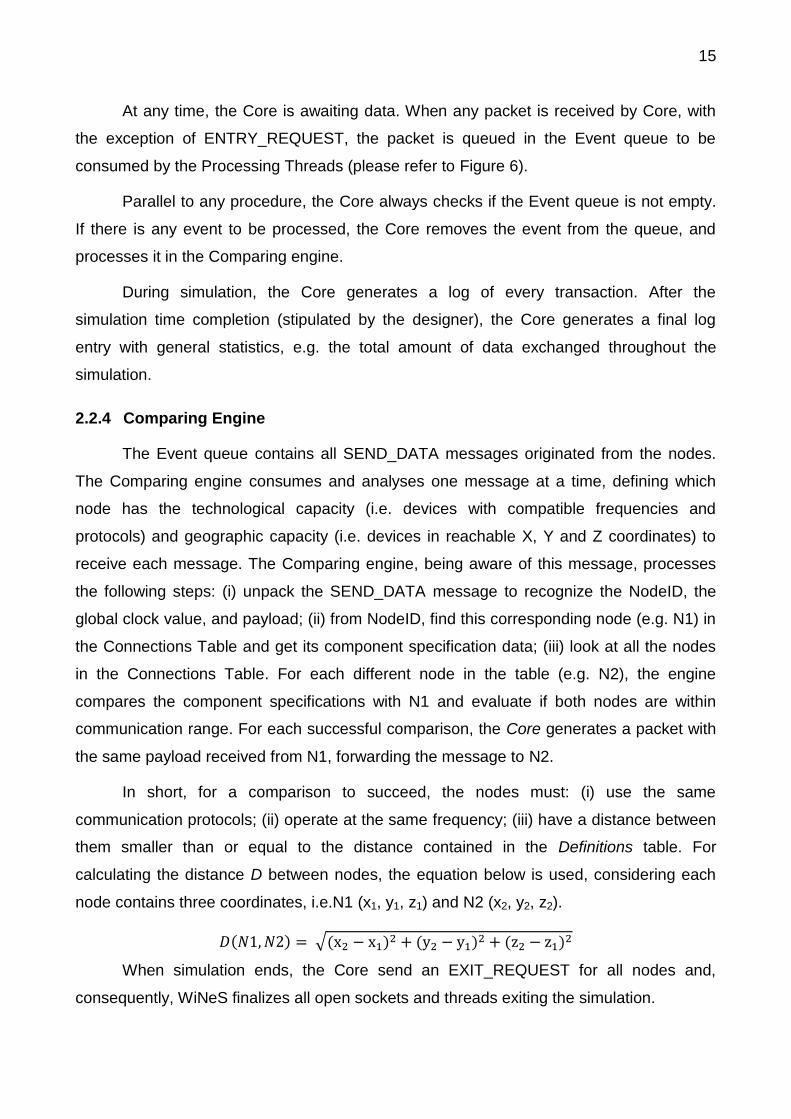
In short, for a comparison to succeed, the nodes must: (i) use the same
communication protocols; (ii) operate at the same frequency; (iii) have a distance between
them smaller than or equal to the distance contained in the Definitions table. For
calculating the distance D between nodes, the equation below is used, considering each
node contains three coordinates, i.e.N1 (x1, y1, z1) and N2 (x2, y2, z2).
( ) √( ) ( ) ( )
When simulation ends, the Core send an EXIT_REQUEST for all nodes and,
consequently, WiNeS finalizes all open sockets and threads exiting the simulation.

16
3 MODELING EXAMPLES
Several tests were performed to validate and analyze WiNeS functionality. This
section presents two small examples to better understand some capabilities of WiNeS.
3.1 WSN with Heterogeneous Topology
Figure 9 illustrates an example of multiple mesh networks linked by a ring network,
i.e. an example of heterogeneous WSN (Wireless Sensor Network) grid with six mesh
topologies connected by a ring topology. The ellipses are the nodes called RFD (Reduced
Function Device of IEEE.802.15.4 protocol) composing the lowest network level; the
rectangular nodes represent the mesh nodes coordinators called FFD (Full Function
Device) that link all WSNs, establishing a highest level in a ring topology.
100<1,0>
Figure 9 – A grid WSN with heterogeneous topology.
This example demonstrates that WiNeS allows definitions of nodes with ability to
take several functionalities. Over the IEEE 802.15.4 protocol there is a hierarchical
protocol enabling an efficient node communication. Each network level has a node
coordinator that receives packets on the mesh, and forwards them to the next ring
coordinator. The mesh routing algorithm is XY; thus, the message goes primarily to left
horizontally, then vertically upward to reach the coordinator. Each node has a hierarchical
addressing system with coordinates (X, Y), for internal mesh routing, and an ID, for inter
mesh routing (through ring topology).

17
Since all nodes in the network have information in common, it is created a User
defined nodes class, named GridNode, that extends the Abstract node layer of WiNeS
(refer to Figure 1). Thus, GridNode class becomes an application layer. Above GridNode
class, a class RFD or a class FFD are added, i.e. extending the GridNode class.
Therefore, the RFD and FFD classes know their hierarchical address. The Default node
layer was used together with the GridNode for traffic generation. While RFD and FFD
classes implement the routing, the Default node layer initializes the packets generation.
After simulation execution, it is possible to validate communications through a log
file generated from the WiNeS API. This method stores the date and local time of the
machine, the timeslot simulation, and the message. Therefore, Figure 10 illustrates a
section of simulation log, where it is possible to analyze and validate the communication
between nodes and the path of exchanged messages. Note that the message:
<102, 1, 1> 5ºC <100, 2, 2> 10h 42min means that at 10h 42min the node <100, 2, 2> (i.e.
ID=100, X=2, Y=2) detected 5ºC of temperature and need to send this information to node
<102, 1, 1>. The message originated at node <100, 2, 2> is transmitted through the nodes
following the XY routing protocol, aiming to reach the coordinator node (FFD<100, 0, 0>).
Then this message arrives in the ring topology and passes by FFD nodes 100, 101 and
102. When message reaches FFD <102, 0, 0> it starts an XY routing protocol on the target
mesh until reach the target node.
<100, 2, 2> sent <100, 1, 2> (<102, 1, 1> 5ºC <100, 2, 2> 10h 42min) <100, 1, 2> sent <100, 0, 2> (<102, 1, 1> 5ºC <100, 2, 2> 10h 42min) <100, 0, 2> sent <100, 0, 1> (<102, 1, 1> 5ºC <100, 2, 2> 10h 42min) <100, 0, 1> sent <100, 0, 0> (<102, 1, 1> 5ºC <100, 2, 2> 10h 42min) <100, 0, 0> sent <101, 0, 0> (<102, 1, 1> 5ºC <100, 2, 2> 10h 42min) <101, 0, 0> sent <102, 0, 0> (<102, 1, 1> 5ºC <100, 2, 2> 10h 42min) <102, 0, 0> sent <102, 1, 0> (<102, 1, 1> 5ºC <100, 2, 2> 10h 42min) <102, 1, 0> sent <102, 1, 1> (<102, 1, 1> 5ºC <100, 2, 2> 10h 42min)
Figure 10 - Event log example for heterogeneous topology.
3.2 Heterogeneous Star Topology
Figure 11 presents a star topology with seven passive RFID tags, a wireless sensor
node and a central node that is a heterogeneous sensor/RFID reader with the ability to
communicate with both RFID tags and sensors.

18
NodeId:108<-1,1,4>
NodeId:107<-1,0,0>
NodeId:106<-1,-1,4>
NodeId:105<0,-1,0>
NodeId:104<1,-1,4>
NodeId:103<1,0,0>
NodeId:102<1,1,4>
NodeId:100<0,1,0>
NodeId:101<0,0,2> RFID/Sensor reader
Wireless Sensor
RFID passive tag
Figure 11 - Heterogeneous star topology.
This example demonstrates that WiNeS present the ability to describe and simulate
heterogeneous nodes interactions. For this application, a wireless sensor node (i.e.
NodeID=100 and coordinates <X=0, Y=1, Z=0>) requires the values contained in the
passive tags. The data acquisition is made by a heterogeneous node located at a central
position, which is able to communicate with all nodes. Importantly, even if all network
nodes are within the communication range, the simulation is modeled to ensure that the
wireless sensor node does not have the ability to perform the reading of passive tags
directly, because (i) the sensor node is not intended to be a reader, and (ii) the node
respects the hierarchy defined by the star network topology.
Remark that the example uses the (X, Y, Z) coordinates system to place the nodes
in the scenario, demonstrating the possibility of using negative coordinates, as a Cartesian
coordinate plane. However, the addressing system is through the IDs created by WiNeS.
Thus the instantiation of the simulation scenario follows some specification rules:
a) Creation of three types of devices (wireless sensor, RFID/sensor reader and
RFID tag) on the application layer;
b) The wireless sensor (NodeID=100) requires the reading of all values
contained in the RFID tags;
c) The RFID/sensor reader node operates on two different frequencies
(heterogeneous component specification);
d) The seven passive RFID tags have different high level IDs;
e) The seven passive RFID tags cannot start any communication; they wait for
the reader requests.

19
Figure 12 illustrates the network traffic related to RFID tags reading on the star
topology. When a packet with information request is received from the wireless sensor
node (i.e. a message with REQUEST_DATA), the heterogeneous central node (i.e.
NodeID=101) forwards it as a new type of package, which is understandable only by RFID
tags. The reverse process also occurs; the packets originated from RFID tags are
transformed into recognizable messages by the wireless sensor node. The RFID tags
reply to REQUEST_DATA with DATA message, which contains its ID to the central node
that forwards to the wireless sensor node.
Source:100 Target:101 Packet: [REQUEST_DATA 102] Source:101 Target:102 Packet: [Node:100 REQUEST_DATA] Source:102 Target:101 Packet: [DATA 100 ID=334.332.789] Source:101 Target:100 Packet: [DATA ID=334.332.789 Node:102] Source:100 Target:101 Packet: [REQUEST_DATA 103] Source:101 Target:103 Packet: [Node:100 REQUEST_DATA] Source:103 Target:101 Packet: [DATA 100 ID=334.332.790] Source:101 Target:100 Packet: [DATA ID=334.332.790 Node:103]
… Source:100 Target:101 Packet: [REQUEST_DATA 108] Source:101 Target:108 Packet: [Node:100 REQUEST_DATA] Source:108 Target:101 Packet: [DATA 100 ID=334.332.795] Source:101 Target:100 Packet: [DATA ID=334.332.795 Node:108]
Figure 12 – Event log example for a star topology traffic.

20
4 RELATED WORK
There’s a good amount of network simulators currently available, both open source
like J-Sim [4], NS-2 [5], NS-3 [6], OMNet++ [7] and SSFNet [8], and commercial such as
OPNET [9] and QualNet [10]. These same simulators can also be classified based on their
complexity levels.
Simple simulators usually involve the simulation of different network topologies,
deployment scenarios and data traffic between the simulated nodes. Complex simulators,
on the other hand, are capable of simulating network protocols and displaying the
simulation results through detailed graphical interfaces, while also providing development
frameworks for customizing the simulation environment.
WiNeS can be classified as a simple simulator with a few complex characteristics.
Simulations of different network protocols, network topologies and data traffic can all be
accomplished through a development infrastructure that allows the implementation of such
functionalities.
4.1 Castalia
Castalia [9] is a WSN, Body Area Network (BAN) and embedded networks simulator
implemented with OMNeT++’s framework that can be used for testing distributed
algorithms and/or wireless communication protocols, as well as realistic behavioral
simulation of the communication module used by the simulated network sensors. Castalia
is also capable of displaying relevant information about the used communication channels,
energy consumption of its simulated devices and packet exchanges between the
networked nodes.
4.2 SENS – Sensor, Environment, Network Simulator
SENS [12] is a network simulator written in the C++ language for the simulation of
applications used in wireless sensor network environments. It’s composed of four different
modules: application, network, physical and environment. The application module is used
for the simulation of the desired network application. The network module offers three
different models network packets exchanges. The first model sends packets to all the
neighbors of the originating node. The second model simulates packet drops. Lastly, the
third model simulates packet collisions.

21
The physical module of SENS simulator is responsible for the simulation of
transmission power, sensors and actuators, interacting with the environment module,
which works as an interface with all physical phenomena.
SENS is not a very parameterizable simulator and is limited to a specific set of
functionalities that accompany it. One of its big advantages, however, is that the
applications used for the simulations can be ported to real network devices.
4.3 GloMoSim
GloMoSim is a network simulator for mobile wireless devices. It was implemented
using Parsec (Parallel Simulation Environment for Complex Systems), which is an
extension of the C programming language for both sequential and parallel execution of
discrete-event simulation models [13].
The internal architecture of this simulator is very similar to WiNeS, using the same
concept of a network with many nodes running in parallel. Both simulators are also
capable of running a simulation based on a set of parameters provided by the user.
GloMoSim’s simulates nodes existing in a two dimensional plane, where each node
occupies a specific position based on its x and y coordinates. Communication between
devices is based on their distance; however this parameter cannot be changed during
simulation.
Protocol simulation in GloMoSim works in a similar way as in the OSI reference
layer, where network packets traverse each layer of a network stack. Still, protocol
simulation is limited to a set of pre-defined ones that accompany the simulator, something
that, currently, restricts GloMoSim to simulating only IEEE 802.11 [2] wireless devices.
GloMoSim’s goal lies on obtaining usage statics on each layer of the network stack,
such as sent and received data and packet collisions.
4.4 OPNET
OPNET [9] is one of the most popular network simulators in corporate
environments, offering a complete graphical interface that is capable of displaying the
simulated network topology along with configuration used in each networked node.
This simulator works solely on a discrete-event model, therefore the behavior of the
simulation is based on a list of predefined events specified by the user.
22
4.5 NS-2
NS-2 [5] is discrete-event network simulator written in the C++ programming
language. Created as a general purpose network simulator, NS-2 is capable of simulating
both wired and wireless networks. Its event scheduler is of particular interest, since it runs
independently off the simulation control system, facilitating the customization of the
different events that will take place during the simulation process.
NS provides an extensive library of pre-defined simulation components, but it also
offers a development infrastructure for implementing new types of devices. These devices
can be either created from scratch or implemented on top of already existing ones.
WiNeS shares a few similarities with NS-2 in which its event scheduler maintains
the simulated devices synchronized with the simulation clock and each device has access
to the event scheduler.
Scripts used for configuring the simulation environment, initializing the event
scheduler and triggering data traffic sources are all written in OTcl, which is an extension
of the Tcl scripting language developed by the MIT [5].
NS-2 is object oriented, which is an advantage due to its modularity, however this
very advantage becomes an obstacle for simulation scenarios with a large amount of
simulated nodes, like WSN. Since each network node represents an object that can
interact with others, this creates a large number of dependencies that need to be checked
at each interval. A disadvantage of NS-2 in wireless networks comes from a lack of
available customizability, since most of the models are not to wireless systems.
4.6 NS-3
NS-3 [6] was created as a replacement for NS-2 [5]. However, it’s not a simple
update of NS-2 with added functionality. NS-3 was completely redesigned to eliminate NS-
2’s shortcomings. Because of this, there’s no compatibility of any sort between both
simulators. Written in C++ and Python, NS-3 is a highly complex network simulator for
both wired and wireless devices.
It offers a large library of pre-implemented devices for a wide variety of network
topologies. This availability of pre-existent content is very useful for quickly evaluating
different simulation scenarios. However, due to the inherent complexity of these simulated
devices, implementing new content for NS-3 is also a complex task.

23
NS-3 focuses on delivering components and protocols as real as possible for
increased fidelity in its simulations, as well deploying virtualization technologies for utilizing
multiple computers for simulating a large amount of devices.
4.7 OMNeT++
OMNeT++ [7] is a modular simulation framework written in the C++ programming
language based on discrete events. Each component of this simulator is based on
modules that can be hierarchically nested for creating composite modules. Simple
modules are used for defining algorithms and are located last in the hierarchy, while
composite modules are composed of simple modules that interact with one another
through message exchanging. Any of these modules can also be used in different
simulation projects. A good example is a network sensor where each of its modules
implements one layer of the protocol stack.
This modular approach gives OMNeT++ a greater flexibility for implementing
different network scenarios. However, just like with NS-2 and NS-3, a greater level of
understanding on how these modules interact with each other is required by the user for
creating new modules.
OMNeT++ offers a robust graphical interface and the possibility of plotting the
network scenario and simulation results. It also comes with a kernel library for creating
new modules different network algorithms. Other simulators are also built on top of
OMNeT++’s framework. These features make OMNeT++ one of the most used network
simulators today.
4.8 Overview
A research, summarized on Table 1, was conducted to compare the simulators
previously mentioned.

24
Table 1 – Overview of the key features of network simulators.
Castalia SENS GloMoSim OPNET NS-2 NS-3 OMNeT++ WiNeS
Event Model DE ARE DE DE DE DE DE DE, SRE, ARE
Network Type Wireless Wireless Wireless Wired/Wireless Wired Wired/Wireless Wired/Wireless Wireless
GUI Yes No No Yes No No Yes No
Expansibility Yes Unknown Yes Unknown Yes Yes Yes Yes
Programming Language
C++ (top of OMNeT++)
C++ PARSEC C/C++ C++ and
OTcl C++ and Python C++ Java
Scalability Low Low High Low (high with virtualization)
Low Low (high with virtualization)
Low High
Platform Windows, Linux, OS X
Linux Windows,
Linux Windows, Linux
Linux, OS X, FreeBSD
Linux, FreeBSD, Mac OS X
Windows, Linux, OS X
Any
Complexity Medium Low Medium Medium High High Medium Low
Virtual Simulation No No No Yes No Yes No No
Legend: DE – discrete event; SRE – synchronous reactive; ARE – asynchronous reactive
The surveys [14] and [16] helped with the main features, the survey [15] helped with
more information of simulator OPNET and the survey [17] helped with the programming
languages and the limitations of the simulators. In conjunction with the study of each
simulator separately, it was possible to create the Table 1 which displays an overview of
the key features of the previously mentioned network simulators, along with WiNeS itself.
25
5 CONCLUSION
The technological trend of forming heterogeneous wireless networks creates a need
to design flexible simulators. The goal is saving time for these networks deployment, and
also allows lower costs by buying fewer devices, ensuring the same signal coverage
compared to deployments without the use of simulators. Nevertheless, WiNeS framework
was developed to be a simulation system for protocols and architectures for wireless
networks, from scenarios predetermined by designers within a simple API. According to
the experimental results, the test scenarios were successfully simulated, and the
communications among the nodes have been contemplated in accordance with the rules
designed. Moreover, the proposed simulations of heterogeneous elements show that
WiNeS is able to simulate new emerging trends with the union of wireless technologies.
However, WiNeS is susceptible to some disadvantages due to its flexibility in
modeling a wide variety of wireless network scenarios and some design approaches, such
as: (a) there is a limit on how many open sockets an operating system can accommodate
and how many threads can be handled efficiently. In a network scenario with 1000 nodes,
we are looking at 3000 threads to model these nodes, 1000 client sockets and 1000 server
sockets; (b) the overall simulation performance is also related to the nodes operations
complexity. Despite of that, WiNeS presents remarkable advantages: (i) the project was
developed in Java, then multiplatform; (ii) simulation of various scenarios, including those
with heterogeneous elements; (iii) the API is simple and easy to understand; (iv) allows the
inclusion of separately modules in Java; (v) also allows the simulation of wired networks, if
needed only ignoring environment settings such as the distance verification between
communicating nodes.
Comparing WiNeS with major simulators, it can be concluded that all intend the
same goal of facilitating the creation of communication network topologies.

26
6 REFERENCES
[1] Y.-S. Chen; Y.-W. Lin; C.-Y. Chang. An overlapping communication protocol
using improved time-slot leasing for Bluetooth WPANs. Journal of Network and
Computer Applications, v. 32, n. 1, pp. 273-292, Jan. 2009.
[2] Institute of Electrical and Electronics Engineers, Inc. Std. 802.11 IEEE - 1999 ed.:
Wireless LAN Medium Access Control (MAC) and Physical Layer (LHY)
Specification, IEEE Press, 90p., 1999.
[3] S. Farahani. ZigBee and IEEE 802.15.4 Protocol Layers. ZigBee Wireless
Networks and Transceivers, Chapter 3, pp. 33-135, 2008.
[4] J. Miller, A. Seila, X. Xiang. The JSIM web-based simulation environment. Future
Generation Computer Systems, v. 17, n. 2, pp. 119-133, Oct. 2000.
[5] NS-2. The Network Simulator ns-2: Documentation.
Capturedonwww.isi.edu/nsnam/ns/ns-documentation, Sep. 2012.
[6] NS-3. ns-3 Network Simulator. Captured on www.nsnam.org/ns-3-
15/documentation, Sep. 2012.
[7] J. Chen et al. The Development of a Realistic Simulation Framework with
OMNeT++. Conference on Future Generation Communication and Networking, pp.
497-500, 2008.
[8] S. Yoon; Y. Kim. A Design of Network Simulation Environment Using SSFNet.
Conference on Advances in System Simulation, pp. 73-78, 2009.
[9] A. Rastegarnia; V. Solouk. Performance Evaluation of Castalia Wireless Sensor
Network Simulator. Telecommunications and Signal Processing, pp. 111-115, 2011.
[10] I. Hammoodi; B. Stewart; A. Kocian; S. McMeekin. A Comprehensive Performance
Study of OPNET Modeler for ZigBee Wireless Sensor Networks. Conference on
Next Generation Mobile Applications, Services and Technologies, pp.357-362, 2009.
[11] F. Yahaya et al. Performance Analysis of Wireless Sensor Network. Signal
Processing & Its Applications, pp.400-405, 2009.
[12] K. Lahmar; R. Cheour; M. Abid. Wireless Sensor Networks: Trends, Power
Consumption and Simulators. Modelling Symposium, pp. 200-204, 2012.

27
[13] J. Font et al. Analysis of source code metrics from ns-2 and ns-3 network
simulators. Simulation Modelling Practice and Theory, v. 19, n. 5, pp. 1330-1346,
May 2011.
[14] H. Hasbullah et al. A Survey of Simulators, Emulators and Testbeds for Wireless
Sensor Networks. International Symposium in Information Technology, pp. 897-902,
2010.
[15] J. Pan; R. Jain. A Survey of Network Simulation Tools: Current Status and
Future Developments. Captured on www.cse.wustl.edu/~jain/cse567-
08/ftp/simtools, Apr. 2012.
[16] M. Tiwari et al. A Survey of Simulation in Sensor Networks. International
Conference on Computational Intelligence for Modelling, Control and Automation, pp.
867-872, 2008.
[17] H. Sundani et al. Wireless Sensor Networks Simulators: A Survey and
Comparisons. International Journal of Computer Networks, pp. 249-265, 2011.