
Universidade do Minho - repositorium.sdum.uminho.pt · Universidade do Minho Escola de Engenharia...
117
Transcript of Universidade do Minho - repositorium.sdum.uminho.pt · Universidade do Minho Escola de Engenharia...

Universidade do MinhoEscola de EngenhariaDepartamento de Informática
Filipe Manuel Gonçalvespg25309
Computer-Interpretable Guidelinesin Decision Support Systems
Creation and Editing of Clinical Protocolsfor Automatic Interpretation
Master dissertationMaster Degree in Computer Science
Dissertation supervised byPaulo Jorge Novais
December 2016
A C K N O W L E D G E M E N T S
The completion of a dissertation thesis involved not only the study of one researcher, butalways the contribution of several researchers who have devoted much of their time tocontribute their studies to the scientific community. As such, I thank you all to those whocontributed to the development of this project.
I would like to thank my advisor, Professor Paulo Jorge Freitas de Oliveira Novais, whodemonstrated the availability, the trust in my work, for the good advices, and especially themotivation conveyed.
Special thanks to my co-advisor Tiago José Martins Oliveira for the attention he gave, theclarifications provided, for the opportunity to work in this great project, for the confidenceplaced in me and for his friendship and patience that has been shown throughout the wholeprocess.
I thank all my friends who always supported me in good and bad moments.And last but not least, a big thanks to the most important people in my life, my father
Fernando Gonçalves and my grandmother Laura Albuquerque, who always provided mewith the means, guidance and support to achieve my dreams.
As such, I dedicate this work to those I love the most.
i
A B S T R A C T
Currently in the health sector there is a growing need to standardize and promote theimprovement of clinical practice in order to reduce costs, which requires a solution thatwill allow these goals to be more easily achieved. To this end, the solution that gathersthe current interest is the use of clinical protocols and promoting conformity with practicescontained in them.
Clinical protocols aim to improve the quality of the clinical process, reducing variationsin clinical practice and reducing health care costs. In order to be effective, these parametersmust be integrated into the care flow and provide specific advice to a patient, regardless oftime or place. Thus, their formalization as Computer-Interpretable Guidelines (CIG) makespossible the development of decision support systems based on CIGs, which may have agreater impact on the behavior of health professionals.
However, the absence of a general pattern in terms of CIG often hinders progress in thedevelopment of these systems. Currently available tools for creating and editing clinicalprotocols for automatic interpretation are not functional or user-friendly. Most of them areacademic projects developed in obsolete languages.
As a means to solve this issue, this dissertation project presents an user-friendly tool thatmanages the creation and editing of CIGs, without requiring the user to have programmingknowledge, and through the use of interfaces that are simple and intuitive.
Keywords - Artificial Intelligence in Medicine, Clinical Decision Support System, Clini-cal Protocols, Computer-Interpretable Guidelines.
ii
R E S U M O
Atualmente no setor da saúde há uma crescente necessidade de padronizar e promover amelhoria das práticas clínicas com o intuito de reduzir custos, o que exige uma soluçãoque permita que estes objetivos sejam mais facilmente atingidos. Para o efeito, a soluçãoque mais desperta o interesse atualmente é a utilização de protocolos clínicos e reforço daconformidade com as práticas que neles são recomendadas.
Os protocolos clínicos visam melhorar a qualidade do processo clínico, reduzindo asvariações da prática clínica e reduzindo os custos de saúde. De forma a serem eficazes, de-vem ser integrados no fluxo de atendimento e prestar aconselhamento específico para umpaciente, independentemente do tempo ou local onde se encontram. Assim, a sua formal-ização como Computer-Interpretable Guidelines (CIGs) torna possível o desenvolvimentode sistemas de apoio à decisão baseados em CIGs, que apresentam uma maior capacidadede afetar o comportamento dos profissionais de saúde.
Contudo, a inexistência de um padrão generalizado a nível das CIGs dificulta muitasvezes o progresso no desenvolvimento destes sistemas. As ferramentas atualmente disponíveispara a criação e edição de protocolos clínicos para interpretação automática não são fun-cionais ou de fácil utilização. Como meio de resolver esta questão, neste projeto de dis-sertação propõe-se o desenvolvimento de uma ferramenta user-friendly capaz de gerir acriação e edição de CIGs, sem a necessidade do utilizador apresentar conhecimentos deprogramação, e através do uso de interfaces que sejam simples e intuitivas.
Keywords - Inteligência Artificial em Medicina, Sistema de Apoio à Decisão Clínica, Proto-colos Clínicos, Guiões Computer-Interpretable.
iii
C O N T E N T S
1 introduction 1
1.1 Motivation 1
1.2 Clinical Protocols 2
1.3 Clinical Decision Support System 2
1.4 Computer-Interpretable Guidelines 3
1.5 Advantages of structured formats of CIGs 4
1.6 Scope 5
1.6.1 e-Health 5
1.6.2 Artificial Intelligence in Medicine 6
1.7 Theme and Objectives 7
1.8 Research Methodology 8
1.9 Document Structure 9
2 state of the art in computer-interpretable guidelines tools 11
2.1 Protégé Desktop 11
2.2 SAGE Workbench 13
2.3 Tallis 16
2.4 GEM Cutter 17
2.5 Asbru View 19
2.6 Discussion 21
3 clinical protocols in compguide 23
3.1 Web Ontology Language 23
3.2 CompGuide Ontology 24
3.3 OWL Structure 27
3.4 Domain Model 28
3.5 System Actors 31
3.5.1 Administrator 31
3.5.2 Health Professionals 32
3.6 Requirement Analysis 32
3.6.1 Functional Requirements 32
3.6.2 Non-Functional Requirements 33
3.7 Use Cases 35
3.7.1 Use Cases Diagram 35
3.7.2 Description of Use Cases 37
3.8 Discussion and Analysis 38
iv
Contents v
4 implementation in protégé desktop 39
4.1 Technologies and Tools used 39
4.2 Software Architecture 40
4.3 Class Diagrams 45
4.4 Sequence Diagrams 49
4.5 Plug-in Interface 51
4.5.1 Individuals by type and OntoGraf Interface 54
4.5.2 CompGuide Wizard Options Interface 57
4.5.3 CompGuide Git ontology Repository 62
4.5.4 CompGuide Java Server Repository 64
4.5.5 Adding CompGuide Editor View to other Protégé Desktop plug-ins 65
4.6 Discussion and Analysis of the Solution 66
5 conclusion 68
5.1 Accomplishment of the Objectives and Contributions 68
5.2 Limitations and Perspectives for future work 70
a use case text descriptions 78
b sequence diagrams 86
c interface figures 99
N O TAT I O N A N D T E R M I N O L O G Y
notation
Throughout the document acronyms related to the representation of names of models andclinical protocols are used. In order to best understand them, this chapter was created inorder for the reader to understand their interpretation.
acronyms
IT - Informatics TechnologyAI - Artificial IntelligenceAIM - AI in MedicineCDSS - Clinical Decision Support SystemCIG - Computer-Interpretable GuidelinesCP - Clinical ProtocolCPG - Clinical Protocol GuidelineCDS - Clinical Decision SupportJDK - Java Development KitJVM - Java Virtual MachineAPI - Application Programming InterfaceIDE - Integrated Development EnvironmentIOM - Institute of MedicineOS - Operational SystemOWL - Web Ontology LanguageIRI - Internationalized Resource IdentifierXML - eXtensible Markup LanguageRDF - Resource Description FrameworkW3C - World Wide Web ConsortiumSHOE - Simple HTML Ontology ExtensionsOIL - Ontology Inference LayerDAML - DARPA Agent Markup LanguageTNM - Task Network ModelSAGE - Standards-based Shareable Active Guideline EnvironmentProtégé - Ontology Editor and Knowledge Acquisition System
vi

Contents vii
GEM - Guideline Elements ModelDTS - Distributed Terminology SystemOKBC - Open Knowledge Base Connectivity ProtocolUML - Unified Modelling LanguageTCP - Transmission Control ProtocolIP - Internet Protocol
L I S T O F F I G U R E S
Figure 3 Tallis Composer Interface (extracted from (Lozano et al., 2009)). 17
Figure 4 GEM Cutter Interface (extracted from (Michel and Shiffman, 2009)).18
Figure 5 Treating Tobacco Use and Dependence Guideline Example in GEMCutter (extracted from (Michel and Shiffman, 2009)). 19
Figure 6 Asbru View Interface (extracted from (Huber, 2005)). 20
Figure 7 Initial formalization of a ClinicalPracticeGuideline for Colon Cancer(extracted from (Oliveira et al., 2014)). 26
Figure 8 Example of ClinicalPracticeGuideline Model presented in Protégé Desk-top Application 28
Figure 9 CompGuide CIG Domain Model 29
Figure 10 CompGuide Editor Use Case Diagram 36
Figure 11 The OWL plug-in in the Protégé Desktop core system (extracted from(Knublauch et al., 2004)) 41
Figure 13 CompGuide System. 45
Figure 14 Class Diagram - CPG and Plan Clinical Task. 46
Figure 15 Class Diagram - Action Clinical Task. 47
Figure 16 Class Diagram - Clinical Action Types. 48
Figure 17 Class Diagram - Question Clinical Task. 48
Figure 18 Class Diagram - Decision Clinical Task. 49
Figure 19 Edit CPG Sequence Diagram. 50
Figure 20 Home Interface of Protégé Desktop application 52
Figure 21 Enabling CompGuide Editor plug-in in Protégé Desktop application 52
Figure 22 CompGuide Editor plug-in interface in Protégé Desktop application 53
Figure 23 CompGuide Editor plug-in interface in Protégé Desktop application af-ter CompGuide ontology is loaded. 54
Figure 24 OntoGraf View in CompGuide Editor plug-in Tab. 55
Figure 25 Filtering Node/Arc in OntoGraf View. 55
Figure 26 Options shown when right clicking a node in OntoGraf View. 56
Figure 27 Configure Node Tooltips and the Export Graph as Image options inOntoGraf View. 56
Figure 28 CompGuide Wizard Options View. 57
Figure 29 CompGuide Wizard Class Selection Window. 58
viii
List of Figures ix
Figure 30 CompGuide Wizard Clinical Task Selection Window. 59
Figure 31 CompGuide Wizard Clinical Action Selection Window. 59
Figure 32 CompGuide Share ontology Window. 62
Figure 34 Upload/Update CompGuide Git Master Branch Repository files. 64
Figure 35 CompGuide Java Server Repository - System Output. 64
Figure 36 CompGuide Java Server Repository - Files Management. 65
Figure 37 CompGuide Java Server Repository - Unziping Received Files. 65
Figure 38 Protégé Desktop plug-ins - Adding CompGuide Editor View into ProtégéDesktop Tab. 66
Figure 39 Create CPG Sequence Diagram. 86
Figure 40 Delete CPG Sequence Diagram. 87
Figure 41 Create Plan Clinical Task Sequence Diagram. 88
Figure 42 Edit Plan Clinical Task Sequence Diagram. 89
Figure 43 Delete Plan Clinical Task Sequence Diagram. 90
Figure 44 Create Action Clinical Task Sequence Diagram. 91
Figure 45 Delete Action Clinical Task Sequence Diagram. 92
Figure 46 Create Option Sequence Diagram. 93
Figure 47 Edit Option Sequence Diagram. 93
Figure 48 Delete Option Sequence Diagram. 94
Figure 49 Create Condition Sequence Diagram. 95
Figure 50 Edit Condition Sequence Diagram. 96
Figure 51 Delete Condition Sequence Diagram. 97
Figure 52 Download CompGuide ontology Sequence Diagram. 97
Figure 53 Share CompGuide ontology Sequence Diagram. 98
Figure 54 CPG Scope - Clinical Specialties Selection Window. 99
Figure 55 CPG Scope - Conditions applied in CPG Selection Window. 100
Figure 56 CPG Plan - Plan Selection Window. 100
Figure 57 Clinical Tasks - Description Window. 101
Figure 58 Action/Plan Periodicity - Periodicity Restriction Values Window.101
Figure 59 Action/Plan Periodicity - Periodicity Restriction Stop Conditions Win-dow. 102
Figure 60 Action/Plan Duration - Duration Restrictions Values Window. 102
Figure 61 Clinical Task - Next Clinical Task Type Selection Window. 103
Figure 62 Clinical Condition - Clinical Restriction Values Window. 103
Figure 63 Clinical Condition - Clinical Temporal Restriction Values Window.104
Figure 64 Clinical Condition - Deletion of Condition individuals Window. 104
L I S T O F TA B L E S
Table 1 Comparison Table of Managing Tools for CIGs. 22
Table 2 Create Wizard Use Case Text Description 79
Table 3 Edit Wizard Use Case Text Description 80
Table 4 Delete Wizard Use Case Text Description 81
Table 5 Download CompGuide CIG Use Case Text Description 82
Table 6 Share CompGuide CIG Use Case Text Description 83
Table 7 Download Shared CompGuide CIG Use Case Text Description 84
Table 8 Access files Use Case Text Description 84
Table 9 Update CompGuide files Use Case Text Description 85
x
1
I N T R O D U C T I O N
This document was developed as a Master’s dissertation in Computer Science at the Uni-versity of Minho. It is entitled Computer-Interpretable Guidelines in Decision Support Systems:Creation and Edition of Clinical Protocols for Automatic Interpretation in Clinical Decision SupportSystems.
The work covers areas of computer science such as Artificial Intelligence (AI), e-Health,Medical Informatics and Clinical Decision Support Systems (CDSS).
In this chapter the motivation and background of this work will be presented, followedby a short explanation of the theme and objectives to accomplish, the research method used,and the structure of the document.
1.1 motivation
The possibility of developing programs that simulate intelligent behavior, took the form ofAI, a term coined by John McCarthy (McCarthy, 2001). According to Eysenck and Keane(1994), the human being can be seen as an information processor. When making a con-nection between mind and computer, through AI, it became possible to develop modelsbased on neural systems, trying to mimic the human being in its complexity, teaching thecomputer to think (Eysenck and Keane, 2005). Since then, researchers have been dreamingof creating an electronic brain. Of all the modern technological missions, this research tocreate AI in computer systems has been one of the most ambitious and controversial.
From the early developments in AI, researchers and doctors were interested in the po-tential that technology can have in medicine. With intelligent computers able to store andprocess vast amounts of knowledge, the hope was that they would become perfect doctors,assisting or surpassing health professionals in tasks such as diagnosis.
Clancey and Shortliffe (1984) provided the following definition: "AI in Medicine mainlydeals with the construction of AI programs that perform diagnoses and therapy recommen-dations" (Clancey and Shortliffe, 1984).
1
1.2. Clinical Protocols 2
1.2 clinical protocols
Clinical Protocols (CPs) are decision tools that allow to shorten the distance between theactual clinical practice and the optimal clinical practice. However, they are also described asdocuments developed in a systematic way to improve the quality of care, reduce unjustifiedvariations in medical practice and reduce health care costs . In order to be effective, clinicalprotocols should be integrated into the flow of care and provide specific advice for eachpatient, when and where needed. The main objectives to be achieved by CPs are improvingthe delivery of health care to patients, decreasing costs and reducing the variability ofmedical practice (ten Teije et al., 2008).
The development of guidelines reflects a drive towards evidence-based medicine, and isdesigned to achieve a reduction in practice variation, and some degree of standardizationof clinical practice for the benefit of patients. This standardization is agreed to be the bestway to reduce medical error, which is acknowledged to be a problem in medicine ( (Leapeet al., 1993) and (Gopher et al., 1989)).
Although medicine is a complex and hazardous business, Leape (1993) points out thatan error rate of 1%, as found in Gopher’s study (1989) of an intensive care unit, would beunacceptable in other high hazard industries. Moreover, recent high visibility cases of errorhave brought the issue to the attention of the public, and there is growing concern aboutthe accountability of health professionals. One reason why the use of protocols may be par-ticularly difficult to manage in medicine concerns the professional independence fosteredby the culture of medicine. In other industries one of the main methods for implementingprotocols involves monitoring and enforcement. The fact that the practice of health pro-fessionals is largely self-regulated may explain why much of the medical research on CPsto date, which concentrates on compliance rates, has shown that compliance appears to below (Grilli and Lomas, 1994).
All of these factors mean that there is a growing interest in getting health professionals,and especially doctors, to follow newly introduced CPs. Given that the number of CPs isset to increase, it is important to understand the attitudes of health professionals to theiruse.
1.3 clinical decision support system
The general idea of CDSSs is that of computer programs that help doctors make diagnoses.Although computers play a number of important clinical functions, people have recognizedsince the early days of computing that computers can support health professionals, helpingthem to filter out the vast collections of possible diseases, findings and treatments (Khalifa,2014).
1.4. Computer-Interpretable Guidelines 3
CDSS are experts in the clinical area designed to help doctors and other health profes-sionals in the clinical process , in tasks such as determining the diagnosis based on patientdata (Berner, 2007).
However, they are viewed with some scepticism by health professionals. The reasonis that these tools can promote other types of errors related to the entry and retrieval ofinformation, and communication failure. The goal of treatment is to manage the trajectoryof a patient in order to produce an improvement in his medical condition, which implies ahigh level of detail of the information used to make decisions.
1.4 computer-interpretable guidelines
The implementation of CPs in CDSSs has the potential of improving the acceptance andapplication of CPs in daily practice, because the systems are able to monitor the actionsand observations of health professionals and provide advice at the point of care (de Clercqet al., 2004).
CIGs are increasingly applied in various fields. According to the Institute of Medicine(IOM), these decision support systems are in fact crucial elements in long-term strategiesfor promoting the use of guidelines (Field et al., 1992).
The conversion of computer algorithms from their text versions is not an easy task , asthese versions were not originally designed to be interpretable by computers and in somecases contain complex instructions , which handle too many variables and it is difficultto translate into efficient algorithms (Chim, JCS and Cheung, NT and Fung, H and Wong,2003).
Sometimes the vocabulary used in the documents is evasive, featuring words to quantifymeasures rather than numerical limits, and the criteria in the decision points are not alwaysexplicit and indicate what to do. The lack of precision of concepts gives rise to ambiguityand gaps in knowledge, in which computers can’t handle (Chim, JCS and Cheung, NT andFung, H and Wong, 2003). The greater simplicity and assertiveness of a protocol, the easierit is to adapt to the CIG format.
This led to the development of different CIG models tools by different research groups,covering a wide range of clinical situations (Isern and Moreno, 2008).
According to the Agency for Health care Research and Quality in the USA, the charac-teristics to be fulfilled by clinical guidelines are validity, reproducibility, reliability, clinicalflexibility, clarity and scheduled review. However, most clinical guidelines do not necessar-ily fully satisfy these factors.
Problems in development of guidelines are as follows: The first is the lack of high levelevidence such as randomized controlled trials, which influences recommendation grade.
1.5. Advantages of structured formats of CIGs 4
The second is the ease of clinical application. Evidence based clinical guidelines are notlikely to be easy to use if sufficient high-level scientific evidence is not available.
Despite these efforts, only a few systems have progressed beyond the prototype statusand research project. Build systems that are accepted by professionals in this area provedto be a difficult task.
1.5 advantages of structured formats of cigs
There are four areas of great importance in the design of CIGs, which should be consideredin the development of CIG format to be used (de Clercq et al., 2004). These areas are:
• Modelling and representation of CPs;
• Acquisition of CPs;
• Verification and test of CPs;
• Implementation of CPs.
Each of them has a number of aspects which serve analysis parameters of different ap-proaches to modelling CIGs. Among the main models of CIGs, the ones to be highlightedare Arden Syntax (developed in University of Columbia (Hripcsak, 1994)), PROforma (de-veloped in the Imperial Cancer Research Fund in England (Fox et al., 1997)), GLIF (devel-oped by InterMed Collaboratory (Patel et al., 1998)), and Asbru (originally developed byUniversity of Standford and currently developed in the Vienna University of Technologyand Ben-Gurion University (Rospocher et al., 2010)).
The representation format of a CIG is an important component for its implementation.However, in the development of CDSSs, there are other steps and technologies that shouldbe highlighted.
A first level to be addressed is the modelling technologies. The object orientation is atechnology that lets you specify the domain CDSS. It is flexible to change, lets you createand implement fully reusable software components (Adratt, Eduardo and LIMA, L andBARRA, 2004).
Other important aspect in the implementation of CIGs is the ability to communicate.Health information should befall technological changes and the data must be shared andreusable, not being constricted by hardware, product or operational system limitations (Adratt,Eduardo and LIMA, L and BARRA, 2004).
The development of formalisms for representing CIGs is an area of great interest, how-ever there is no dominant CIG platform and no system has a widespread use outside theinstitution where they were developed, demonstrating often the inability of these tools increating and editing guidelines (und Naturwissenschaften, 2015).
1.6. Scope 5
By studying the main application properties of these CIGs , the motivation of this projectlies in implementing a user-friendly tool to represent clinical guidelines in a specific model,able to fill the limitations of the existing applications.
1.6 scope
1.6.1 e-Health
E-Health is an emerging field in the intersection of medical informatics, public health andbusiness, referring to health services and information delivered or enhanced through theInternet and related technologies. In a broader sense, the term characterizes not only atechnical development, but also a state-of-mind, a way of thinking, an attitude, and a com-mitment for networked, global thinking, to improve health care locally, regionally, andworldwide by using information and communication technology (Peleg et al., 2003).
The "e" in e-Health does not only stand for "electronic," but implies a number of other"e’s," which together perhaps best characterize what e-Health is all about (or what it shouldbe, namely (Eysenbach, 2001)).
1. Efficiency - one of the promises of e-Health is to increase efficiency in health care,thereby decreasing costs. One possible way of decreasing costs would be by avoidingduplicative or unnecessary diagnostic or therapeutic interventions, through enhancedcommunication possibilities between health care establishments, and through patientinvolvement.
2. Enhancing quality of care - increasing efficiency involves not only reducing costs,but at the same time improving quality. E-Health may enhance the quality of healthcare for example by allowing comparisons between different providers, involving con-sumers as additional power for quality assurance, and directing patient streams to thebest quality providers.
3. Evidence based - e-Health interventions should be evidence-based in a sense that theireffectiveness and efficiency should not be assumed but proven by rigorous scientificevaluation. Much work still has to be done in this area.
4. Empowerment of consumers and patients - by making the knowledge bases of medicineand personal electronic records accessible to consumers over the Internet, e-Healthopens new avenues for patient-centered medicine, and enables evidence-based pa-tient choice.
5. Encouragement of a new relationship between the patient and health professional,towards a true partnership, where decisions are made in a shared manner.
1.6. Scope 6
6. Education of physicians through online sources (continuing medical education) andconsumers (health education, tailored preventive information for consumers).
7. Enabling information exchange and communication in a standardized way betweenhealth care establishments.
8. Extending the scope of health care beyond its conventional boundaries. This is meantin both a geographical sense as well as in a conceptual sense. e-Health enables con-sumers to easily obtain health services online from global providers. These servicescan range from simple advice to more complex interventions or products such a phar-maceuticals.
9. Ethics - e-Health involves new forms of patient-physician interaction and poses newchallenges and threats to ethical issues such as online professional practice, informedconsent, privacy and equity issues.
10. Equity - to make health care more equitable is one of the promises of e-Health, butat the same time there is a considerable threat that e-Health may deepen the gapbetween the "haves" and "have-nots". People, who do not have the money, skills, andaccess to computers and networks, cannot use computers effectively. As a result, thesepatient populations (which would actually benefit the most from health information)are those who are the least likely to benefit from advances in information technology,unless political measures ensure equitable access for all. The digital divide currentlyruns between rural vs urban populations, rich vs poor, young vs old, male vs femalepeople, and between neglected/rare vs common diseases.
However , despite all the benefits that e-Health can provide in clinical areas, through theuse of AI is possible to improve their implementations using CDSS, and CIGs may have anactive role in this improvement, provided that their availability is increased.
1.6.2 Artificial Intelligence in Medicine
AI is the study of ideas which enable computers to do the things that make people seemintelligent. The central goals of AI are to make computers more useful and to understandthe principles which make intelligence possible (Saridis, 2001). AIM is AI specialized tomedical applications.
The earliest work in AIM dates to the early 1970s, when the field of AI was about 15 yearsold (Benko and Sik Lányi, 2009)). Early AIM researchers had discovered the applicabilityof AI methods to life sciences that demonstrated the ability to represent and utilize expertknowledge in symbolic form. The general AI research community was fascinated by theapplications being developed in the medical world, noting that significant new AI methods
1.7. Theme and Objectives 7
were emerging as AIM researchers struggled with challenging biomedical problems. Overthe next decade, the community continued to grow, and with the formation of the AmericanAssociation for Artificial Intelligence in 1980, a special subgroup on medical applicationswas created (Kononenko, 2001).
Though the introduction of personal computers and high-performance workstations itwas possible to develop new types of AIM research and new models for technology dis-semination. If the computer is a useful manager of billing records, it should also maintainmedical records, laboratory data, data from clinical trials, etc. And if the computer is usefulto store data, it should also help to analyse, organize, and retrieve it.
Often, health professionals are skeptical regarding the use of these technologies, becausethey are afraid of losing their jobs. However, this concern is not justified. AI no longer aimsthe substitution of professionals by computer artifacts. AI aims to improve the usabilityof programs for assisting physicians in figuring out what is wrong with the patients andprovide new solutions to help making better decisions (Horn, 2001).
Information technology, in general, can help improving human health and longevity. Toachieve this goal innovative and intelligent software can be deployed in order to improvemedical research, disease prevention, and health care service delivery.
With this work, it’s intended to create a tool that aids in the management of a knowledgebase for automatic execution engine of CIGs. In other words, the creation of the substrateunder which the decision support system works.
1.7 theme and objectives
The theme of this work is the Computer-Interpretable Guidelines in Decision Support Sys-tems: Creation and Editing of Clinical Protocols for Automatic Interpretation. Taking asstarting point CDSSs that use CIGs as support for their knowledge base, the objective ofthis work lies in the study of the main aspects of the creation and editing tools of CIGsfor automatic interpretation that are currently being used. For this we identify aspects thatcould be improved based on the comparison of existing tools, and develop a CIG tool thatincorporates these improvements.
The research questions that guided the execution of work were:
• What creation and editing of CIG tools are being used?
• What aspects could be improved or applied in these tools? (easy-to-use? reliable? toocomplex?)
• How should a new CIG tool be planned? (platform to use? performance? interface?)
• Should a new CIG tool allow for the users to publish their modified CIG files to adevelopment team? (communication?)
1.8. Research Methodology 8
The research questions previously specified allowed us to state the following objectivesto be achieved:
1. Identify key aspects for representing medical knowledge in CDSSs;
2. Identify tools used to create and edit CIGs and their key issues;
3. Identify aspects that could be improved or applied in these tools;
4. Formalize the creation and editing of CPs in the OWL language;
5. Design a tool capable of managing the stored set of parameters in CPs, without theneed for advanced programming skills;
6. Design features capable of generating graphical representations of CPs;
7. Design features capable of downloading the latest CIG files (when the platform isconnected to the web);
8. Design features capable of sending their modified CIG files to the development team(when the platform is connected to the web).
1.8 research methodology
Regarding the research methodology we adopted the action-research methodology (Somekhand Bridget, 2005). Initially a crucial collection of the information was gathered for the con-struction of a solution design process. Then the research of relevant concepts and designsfor the job began. The assimilation of concepts and projects were subject to constant re-newal, as new ideas and information arose. The last part of the work was the developmentof a functional model and prototype that allowed the achievement of the set of goals.
This research methodology has five iterated identifiable phases:
1. Diagnosing - Definition of the problem and its characteristics;
2. Action planning - Constant updating of state of the art and objectives of the work;
3. Action taking - Development of a prototype in order to achieve the defined objectives;
4. Evaluating - Analysis and prototype correction based on the results obtained;
5. Specifying learning - The diffusion of knowledge and results obtained in the scientificcommunity.
1.9. Document Structure 9
As for the development of software solutions the methodology used will be adapted fromSCRUM. As such, all previously explained steps will be applied in software development.The first steps are diagnosing the problem and updating the state of art and objectives ofthe work. Next is the software development of the proposed objectives. With these taskscompleted, an evaluation of the work will be done, whose results are reported in the paper.Through this results, new problems arise which leads to a new cycle.
Scrum development is a simple methodology intended to solve long product develop-ment which allows the developer to focus in the set of goals proposed. This methodologyalso solves the mismatch problem between a product’s business requirement and the actualresulting implementation (which normally occurs when developing big products).
1.9 document structure
This work was structured in five chapters, organized as follows:
1. Introduction - In the first chapter there is a brief description of the current situation,an introduction to key concepts and a presentation of motivation, theme, objectivesand research methodology. Also a brief description of the document is performed;
2. State of the art in Computer-Interpretable Guidelines Tools - The second chapterdeals with creation and editing tools of CIGs, referring its importance and the benefitsand disadvantages of their use. These aspects are subsequently used to point out themain features of some models such as SAGE Workbench, Protégé Desktop, Tallis (whichuses PROForma model), GEM Cutter and Asbru View. At the end of the chapter ananalysis of the key aspects of these tools is performed and their main limitations areidentified;
3. Clinical Protocols in CompGuide - The third chapter analyzes a number of factors re-lated to the CompGuide OWL structure, such as the data structure of the OWL classesused in the CompGuide ontology, its domain model, who will be using this system (sys-tem actors), the plug-in functional and non-functional requirements and its use casediagrams. In the end, a conclusive discussion is made, defining the main conclusionsin this chapter;
4. Implementation in Protégé Desktop - The fourth chapter addresses the system ac-cording to a point of view of implementation and software development based on theanalysis of the problem and according to the studied artifacts in software engineering.Therefore, it is pertinent to address the software architecture, technologies and toolsused, class diagrams, sequence diagrams, a small view of the application interfaces,among others;

1.9. Document Structure 10
5. Conclusion - The last chapter summarizes the work done so far and the main conclu-sions to be drawn;
2
S TAT E O F T H E A RT I N C O M P U T E R - I N T E R P R E TA B L E G U I D E L I N E ST O O L S
This chapter intends to describe the features of existing creation and editing tools of CPs,and discuss and compare their key aspects and main deficiencies.
In computer science, several languages and tools exist for helping users and systemdevelopers in creating good and effective CIGs. In particular, various tools help peoplecreate, either manually or semi-automatically categories, partonomies, taxonomies, andother organization levels of CIGs (Cristani, Matteo and Cuel, 2005). Some of the mostimportant modelling editors and CIG managers are:
• Protégé Desktop;
• SAGE Workbench;
• Tallis;
• GEM Cutter;
• Asbru View;
In the next sub-chapters, all these tools will be explained with more detail.
2.1 protégé desktop
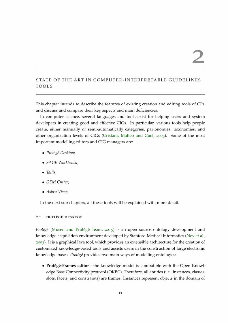
Protégé (Musen and Protégé Team, 2015) is an open source ontology development andknowledge acquisition environment developed by Stanford Medical Informatics (Noy et al.,2003). It is a graphical Java tool, which provides an extensible architecture for the creation ofcustomized knowledge-based tools and assists users in the construction of large electronicknowledge bases. Protégé provides two main ways of modelling ontologies:
• Protégé-Frames editor - the knowledge model is compatible with the Open Knowl-edge Base Connectivity protocol (OKBC). Therefore, all entities (i.e., instances, classes,slots, facets, and constraints) are frames. Instances represent objects in the domain of
11

2.1. Protégé Desktop 12
interest. Classes are either named collections of instances or abstract conceptual enti-ties in the domain (e.g., the concept of a drug ingredient). Slots are binary relationsdescribing properties of classes (e.g., the indications of a drug). Facets describe prop-erties of slots (e.g., the data type of a slot’s value). Constraints specify additionalrelationships that must hold among instances;
• Protégé-OWL editor - enabling users to build ontologies in OWL;
Protégé supports the construction of a domain ontology, the design of customized knowl-edge acquisition forms, and entering domain knowledge that can be adapted to enableconceptual modelling with new and evolving Semantic Web languages. Protégé lets usthink about domain models at a conceptual level without having to know the syntax of thelanguage ultimately used on the Web. We can concentrate on the concepts and relationshipsin the domain and the facts about them that we need to express (Noy, Natalya F and Sintek,Michael and Decker, Stefan and Crubézy, Monica and Fergerson, Ray W and Musen, 2001).
It provides a platform which can be extended with graphical widgets for tables, dia-grams, and animation components to access other knowledge-based systems embeddedapplications. Protégé is a library, which other applications can use to access and displayknowledge bases. It can be extended by way of a plug-in architecture and a Java-based APIfor building knowledge-based tools and applications. Protégé is used to author guidelinesin various models. Part of the modelling can be accomplished using predefined graphicalsymbols. These symbols are arranged in a diagram and linked by graphs. The underlyingdata is entered by forms (Leong et al., 2007).
Protégé ontologies can be exported into a variety of formats including RDF(S), OWL, andXML Schema (Rubin et al., 2007).
Figure 1 shows the interface of the Protégé Desktop application.
1 https://github.com/protegeproject/owlviz
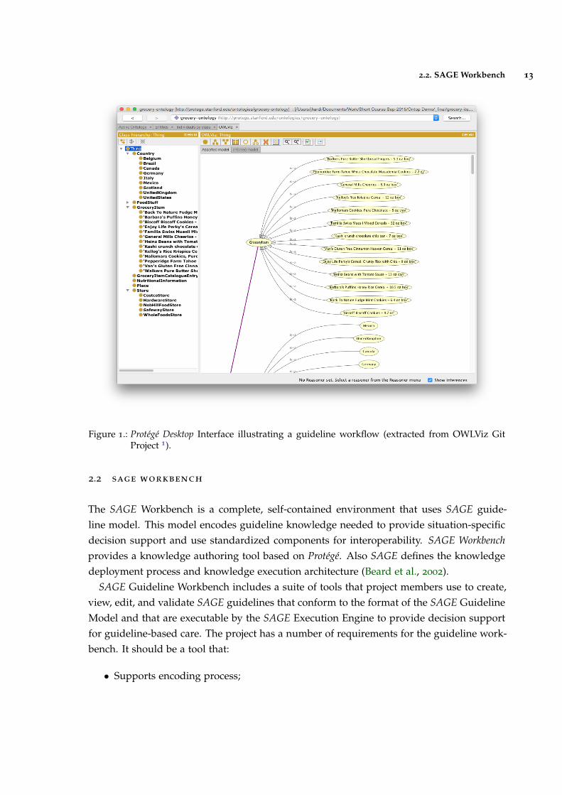
2.2. SAGE Workbench 13
Figure 1.: Protégé Desktop Interface illustrating a guideline workflow (extracted from OWLViz GitProject 1).
2.2 sage workbench
The SAGE Workbench is a complete, self-contained environment that uses SAGE guide-line model. This model encodes guideline knowledge needed to provide situation-specificdecision support and use standardized components for interoperability. SAGE Workbenchprovides a knowledge authoring tool based on Protégé. Also SAGE defines the knowledgedeployment process and knowledge execution architecture (Beard et al., 2002).
SAGE Guideline Workbench includes a suite of tools that project members use to create,view, edit, and validate SAGE guidelines that conform to the format of the SAGE GuidelineModel and that are executable by the SAGE Execution Engine to provide decision supportfor guideline-based care. The project has a number of requirements for the guideline work-bench. It should be a tool that:
• Supports encoding process;

2.2. SAGE Workbench 14
• Provides connection to terminology services to be used during encoding;
• Allows debugging/validation of guidelines;
• Provides a document-oriented view of the guideline knowledge base so that cliniciansand knowledge engineers can easily review the content of the knowledge base.
SAGE Workbench also includes a terminology plug-in (the SAGE DTS tab) which ac-cesses via the Internet the Apelon DTS (Distributed Terminology System) terminology ser-vice (developed by Apelon, Inc., USA). This plug-in allows users to view standard andSAGE-based terminologies, do concept queries, and view complex logical concept expres-sions. The Apelon DTS utilizes client-server technology and access to this functionalityrequires the user to log in to the DTS server. Note that it is not necessary to access Apelon’sterminology service in order to use the workbench or run the demonstration guidelines.
One of its key approaches is to integrate guideline based decision support with the work-flow of care process. In addition, SAGE is recognized as one of the improved ClinicalDecision Support (CDS) architectures with its large coverage of knowledge base. SAGEincludes a knowledge authoring tool based on Protégé.
Therefore, SAGE can be a strong and concrete knowledge representation model for clin-icians (Kim, J and Shim, BinGu and Kim, SunTae and Lee, JaeHoon and Cho, InSook andKim, 2009);
The SAGE website 2 provides a description of the method for encoding SAGE guidelineapplications as well as full documentation on all the software modules making up thepackage. SAGE Workbench is designed for use on MS Windows computers.
The user interface for the SAGE Workbench is organized as a number of tabs as shownin figure 2.
Figure 2.: Tabs shown in the Protégé Desktop platform using SAGE Workbench Plug-in (extractedfrom Sage Website 3).
2 http://sage.wherever.org/
3 http://sage.wherever.org/encoding/encoding_tools.html
2.2. SAGE Workbench 15
• KnowledgeTree Tab allows navigation of frames that are directly and indirectly refer-enced from a selected instance in a tree structure. It allows you to browse and edit,in a single window, all the frames reachable from the top-level instance (usually thetop-level Guideline instance);
• Facet Constraints Tab allows a user to identify and fix all instances in a knowledgebase, or instances of selected classes, that have slots whose values violate constraintsassociated with the slot. If a user wanted to find all instances that had constraintviolating facets in his/her ontology, they had to manually iterate through all the in-stances in their ontology looking for red boxes that identified slots that had constraintviolating facets. The Facet Constraints Tab allows a user to accomplish this task withthe click of one button;
• PAL (Protégé Axiom Language) is a subset of first-order logic which can be used toexpress integrity constraints about a knowledge base. The PAL Constraints Tab is afront-end for this constraint system. This Tab allows a user to create, browse, andmodify constraints in the knowledge base, and to evaluate constraints (either as agroup or individually);
• Apelon terminology Tab and plug-in (i.e. and integration between Apelon softwareand Protégé) works with Apelon DTS 3.0 server across Internet. This plug-in allows asearch of terms from several terminologies and creation of a reference in the Protégéguideline Workbench to a term in a standard terminology;
• Kwiz Tab allows to customize high-level views of the knowledge base, constrainednavigation, reuse of existing knowledge bases, context-sensitive search and help;
• SAGE Tab provides a self-contained testing environment within Protégé for an en-coded guideline. After validating the knowledge base, a user can select data froma test case and run the guideline by simulating the arrival of triggering events. Af-ter evaluating possible immunizations that may be due, it requests information onimmunization consent and serious illnesses that may render immunization inadvis-able. Once responses to the questions are submitted, the SAGE Execution Engine willgenerate its final recommendations for the immunizations that should be given;
• Kb-to-doc Document-generation Tab allows to generate a document-oriented view ofthe contents of the encoded guideline;
2.3. Tallis 16
2.3 tallis
Tallis is a new Java implementation of PROforma-based authoring and execution tools de-veloped by the Cancer Research UK (Sutton and Fox, 2003). Tallis is based on a later versionof the PROforma language model (Steele and Primer, 2002).
Tallis consists of a suite of applications:
• Composer - a desktop graphical editor for authoring PROforma guidelines. Composerincludes a test application for simulating interaction with your PROforma guidelines,and contains default settings for enacting your application in OpenClinical savingyour application in the OpenClinical repository;
• Tester - a desktop application for testing PROforma guidelines. The tester comesbundled with Composer, but may be run as a standalone application if required;
• Web Enactment - a web application for enacting your application on the web, used inOpenClinical;
Each of these applications will run on any platform and integrate with other compo-nents, including third party applications. Yet it requires the Tallis engine and core plug-ins (Martínez-Salvador and Marcos, 2016).
PROforma is a language for describing the activities that are to be carried out by someagent to achieve particular objectives in some situation, possibly under various kinds ofpractical constraints (e.g. timing, resources or information constraints). It combines fea-tures of a specification language as developed in software engineering, and a knowledgerepresentation language as developed in AI (Steele, Rory and Primer, 2002).
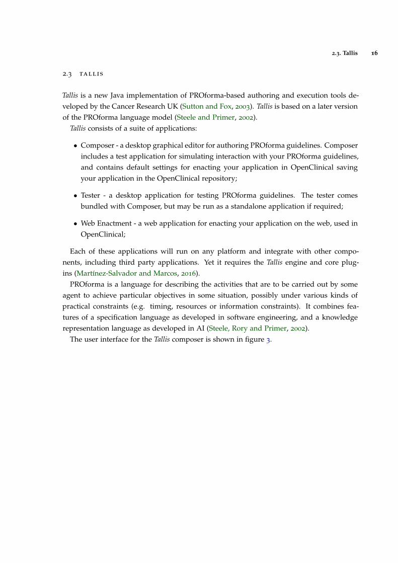
The user interface for the Tallis composer is shown in figure 3.
2.4. GEM Cutter 17
Figure 3.: Tallis Composer Interface (extracted from (Lozano et al., 2009)).
Process-descriptions are displayed in Tallis both in a network view and in a tree view:
• The tree view displays the process-descriptions hierarchical structure;
• The network view displays task ordering according to scheduling constraints;
The hierarchy of a process-description is based on plans: each plan defines a new levelin the hierarchy.
• All the plans can be viewed and their contents at a glance in the tree view;
• The network view is more suited for viewing the contents of one plan at a time;
Task properties can be viewed or edited in the Task Properties window by clicking on thetask in the tree or in the network area.
More details can be found in the user-guide found in their website (Oettinger, 2005).
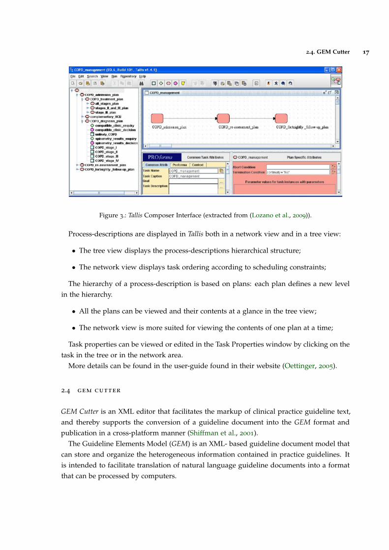
2.4 gem cutter
GEM Cutter is an XML editor that facilitates the markup of clinical practice guideline text,and thereby supports the conversion of a guideline document into the GEM format andpublication in a cross-platform manner (Shiffman et al., 2001).
The Guideline Elements Model (GEM) is an XML- based guideline document model thatcan store and organize the heterogeneous information contained in practice guidelines. Itis intended to facilitate translation of natural language guideline documents into a formatthat can be processed by computers.
2.4. GEM Cutter 18
GEM is intended to be used throughout the entire guideline life-cycle to model infor-mation pertaining to guideline development, dissemination, implementation, and mainte-nance. Information at both high and low levels of abstraction can be accommodated. Useof XML facilitates computer processing of the guideline information (Karras et al., 2000).
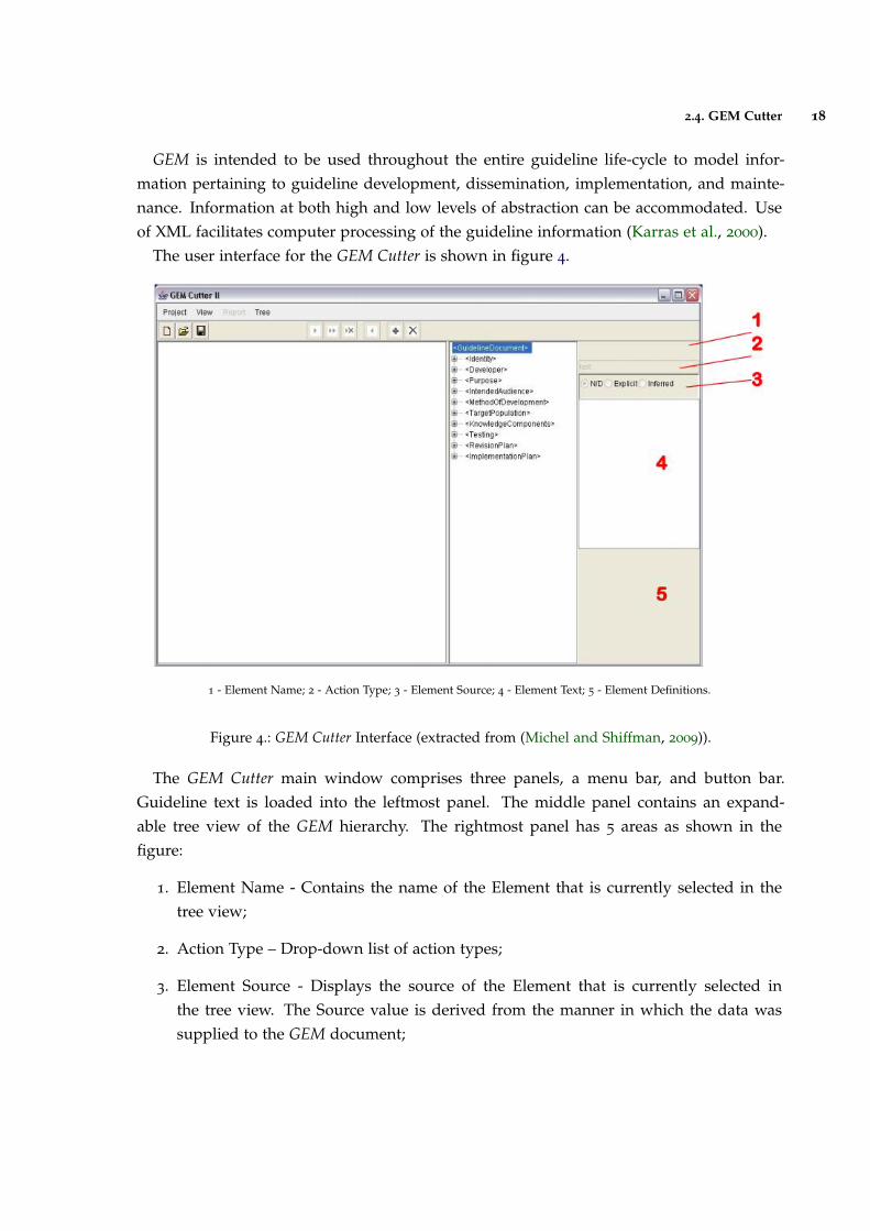
The user interface for the GEM Cutter is shown in figure 4.
1 - Element Name; 2 - Action Type; 3 - Element Source; 4 - Element Text; 5 - Element Definitions.
Figure 4.: GEM Cutter Interface (extracted from (Michel and Shiffman, 2009)).
The GEM Cutter main window comprises three panels, a menu bar, and button bar.Guideline text is loaded into the leftmost panel. The middle panel contains an expand-able tree view of the GEM hierarchy. The rightmost panel has 5 areas as shown in thefigure:
1. Element Name - Contains the name of the Element that is currently selected in thetree view;
2. Action Type – Drop-down list of action types;
3. Element Source - Displays the source of the Element that is currently selected inthe tree view. The Source value is derived from the manner in which the data wassupplied to the GEM document;
2.5. Asbru View 19
4. Element Text - Contains the complete text of the element that is currently selected inthe tree view. Text can be input directly or edited in this window;
5. Element Definitions - Contains the definition of the element that is currently selectedin the tree view;
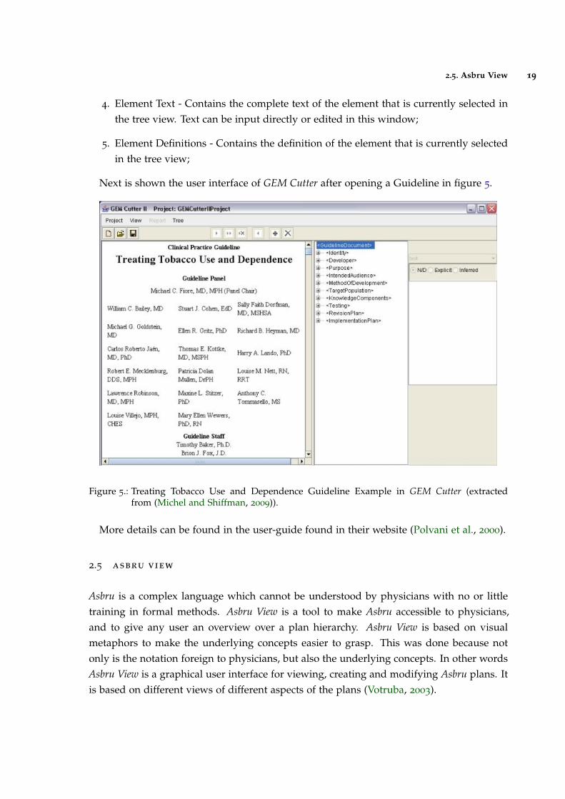
Next is shown the user interface of GEM Cutter after opening a Guideline in figure 5.
Figure 5.: Treating Tobacco Use and Dependence Guideline Example in GEM Cutter (extractedfrom (Michel and Shiffman, 2009)).
More details can be found in the user-guide found in their website (Polvani et al., 2000).
2.5 asbru view
Asbru is a complex language which cannot be understood by physicians with no or littletraining in formal methods. Asbru View is a tool to make Asbru accessible to physicians,and to give any user an overview over a plan hierarchy. Asbru View is based on visualmetaphors to make the underlying concepts easier to grasp. This was done because notonly is the notation foreign to physicians, but also the underlying concepts. In other wordsAsbru View is a graphical user interface for viewing, creating and modifying Asbru plans. Itis based on different views of different aspects of the plans (Votruba, 2003).
2.5. Asbru View 20
Asbru View consists of two main views: Topological View (TopoView) and Temporal View(TempView):
• The Topological View mainly displays the relationships between plans, without aprecise time scale. The basic metaphor in this view is the running track;
• The Temporal View concentrates on the temporal dimension of plans and conditions.In addition to the topological information, physicians need to be able to see the detailsof the temporal extensions of plans. For this purpose, the Temporal View is used. Itconsists of a display that represents each plan with a graphical object whose featureschange with the values they depict;
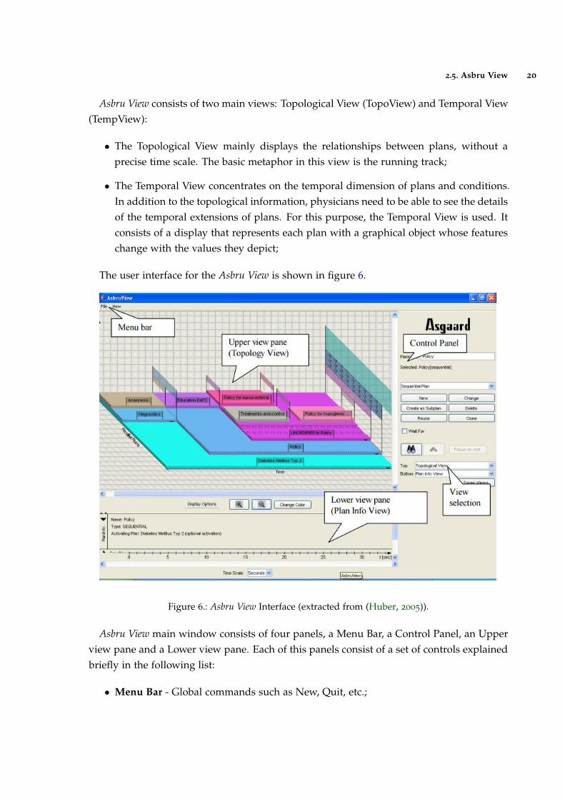
The user interface for the Asbru View is shown in figure 6.
Figure 6.: Asbru View Interface (extracted from (Huber, 2005)).
Asbru View main window consists of four panels, a Menu Bar, a Control Panel, an Upperview pane and a Lower view pane. Each of this panels consist of a set of controls explainedbriefly in the following list:
• Menu Bar - Global commands such as New, Quit, etc.;
2.6. Discussion 21
• Control Panel - Controls to create and modify plans, to focus on plans and to selectthe views shown on the right side of the control panel;
• Upper view pane - The upper view on the plans. The screen-shot shows the TopologyView;
• Lower view pane - Lower view. Can be hidden;
2.6 discussion
Now that the highlighted platforms were properly studied, a small discussion will be madecomparing the key aspects and main deficiencies of each application and determine whatfeatures could be included in the new model.
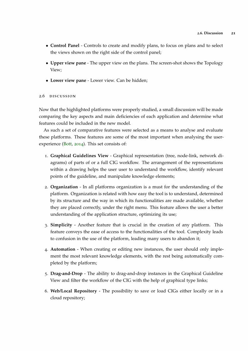
As such a set of comparative features were selected as a means to analyse and evaluatethese platforms. These features are some of the most important when analysing the user-experience (Bott, 2014). This set consists of:
1. Graphical Guidelines View - Graphical representation (tree, node-link, network di-agrams) of parts of or a full CIG workflow. The arrangement of the representationswithin a drawing helps the user user to understand the workflow, identify relevantpoints of the guideline, and manipulate knowledge elements;
2. Organization - In all platforms organization is a must for the understanding of theplatform. Organization is related with how easy the tool is to understand, determinedby its structure and the way in which its functionalities are made available, whetherthey are placed correctly, under the right menu. This feature allows the user a betterunderstanding of the application structure, optimizing its use;
3. Simplicity - Another feature that is crucial in the creation of any platform. Thisfeature conveys the ease of access to the functionalities of the tool. Complexity leadsto confusion in the use of the platform, leading many users to abandon it;
4. Automation - When creating or editing new instances, the user should only imple-ment the most relevant knowledge elements, with the rest being automatically com-pleted by the platform;
5. Drag-and-Drop - The ability to drag-and-drop instances in the Graphical GuidelineView and filter the workflow of the CIG with the help of graphical type links;
6. Web/Local Repository - The possibility to save or load CIGs either locally or in acloud repository;
2.6. Discussion 22
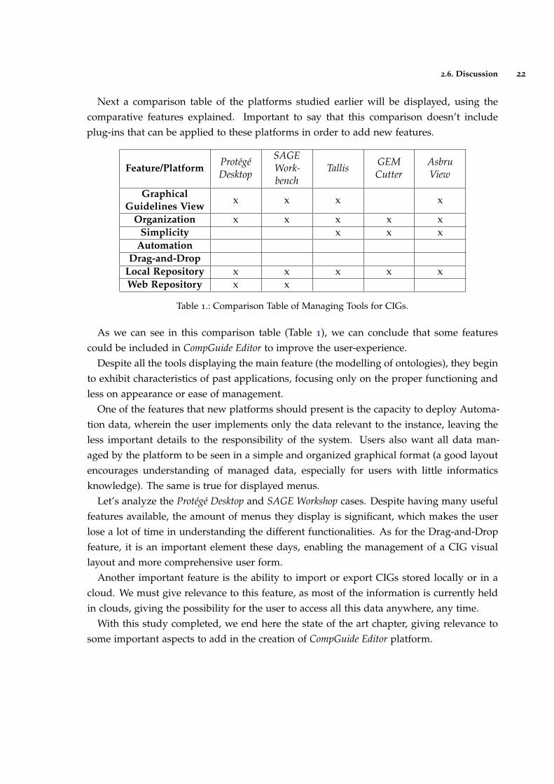
Next a comparison table of the platforms studied earlier will be displayed, using thecomparative features explained. Important to say that this comparison doesn’t includeplug-ins that can be applied to these platforms in order to add new features.
Feature/PlatformProtégéDesktop
SAGEWork-bench
Tallis GEMCutter
AsbruView
GraphicalGuidelines View
x x x x
Organization x x x x xSimplicity x x x
AutomationDrag-and-Drop
Local Repository x x x x xWeb Repository x x
Table 1.: Comparison Table of Managing Tools for CIGs.
As we can see in this comparison table (Table 1), we can conclude that some featurescould be included in CompGuide Editor to improve the user-experience.
Despite all the tools displaying the main feature (the modelling of ontologies), they beginto exhibit characteristics of past applications, focusing only on the proper functioning andless on appearance or ease of management.
One of the features that new platforms should present is the capacity to deploy Automa-tion data, wherein the user implements only the data relevant to the instance, leaving theless important details to the responsibility of the system. Users also want all data man-aged by the platform to be seen in a simple and organized graphical format (a good layoutencourages understanding of managed data, especially for users with little informaticsknowledge). The same is true for displayed menus.
Let’s analyze the Protégé Desktop and SAGE Workshop cases. Despite having many usefulfeatures available, the amount of menus they display is significant, which makes the userlose a lot of time in understanding the different functionalities. As for the Drag-and-Dropfeature, it is an important element these days, enabling the management of a CIG visuallayout and more comprehensive user form.
Another important feature is the ability to import or export CIGs stored locally or in acloud. We must give relevance to this feature, as most of the information is currently heldin clouds, giving the possibility for the user to access all this data anywhere, any time.
With this study completed, we end here the state of the art chapter, giving relevance tosome important aspects to add in the creation of CompGuide Editor platform.
3
C L I N I C A L P R O T O C O L S I N C O M P G U I D E
In order to better understand the created plug-in and its features, it’s crucial to understandfirst the essential points of the CompGuide ontology used in this project. Having that inmind, it’s necessary to approach this matter by analyzing the problems that may appearwhen executing the CPs, according to its classes, individuals, and restrictions associated.As such, this chapter is intended to analyze a set of elements that describe the ontologydomain and the features and actors of the system.
Sub-chapter Web Ontology Language gives a brief description of the OWL languagesand its uses. Sub-chapter CompGuide Ontology explains what is a CompGuide ontology,what is used for, and the advantages of it’s uses. Sub-chapter OWL Structure explainswhat this structure represents and it’s uses. In sub-chapter Domain Model, it’s shownand explained the domain in which the project is inserted. The next sub-chapter (SystemActors) is presented with details about the users that will use both the CompGuide ontologyand the project features. Posteriorly is presented the sub-chapter Requirements Analysisand Gathering where are shown the functional and non-functional requirements necessaryto obtain the desired solution. After this, the sub-chapter Use Cases reveals a graphicaldiagram that allows the reader to better interpret the structure explained in this chapter.
In the last sub-chapter (Discussion and Analysis) is elaborated a discussion and analysisof all spoken themes in this chapter.
3.1 web ontology language
Web Ontology Language (OWL) is a formal language for representing ontologies in theSemantic Web developed by W3C Web ontology Working Group. OWL was primarily de-signed to represent information about categories of objects and how objects are interrelated(the sort of information that is often called an ontology). OWL can also represent infor-mation about the objects themselves (the sort of information that is often thought of asdata) (Horrocks et al., 2003). As OWL is supposed to be an ontology language, it had to beable to represent a useful group of ontology features. As there were already several ontol-ogy languages designed for use in the Web, OWL had to maintain as much compatibility as
23
3.2. CompGuide Ontology 24
possible with the existing languages (SHOE (Heflin et al., 1999), OIL (Patel-Schneider et al.,2001) and DAML+OIL (Mcguinness et al., 2002)).
The multiple influences on OWL resulted in some difficult trade-offs. Somewhat sur-prisingly, considerable technical work had to be performed to devise OWL in such a waythat it could be shown to have various desirable features, while still retaining sufficientcompatibility with its roots (McGuinness et al., 2004).
An OWL ontology describes a domain in terms of classes, properties and individualsand may include rich descriptions of the characteristics of those objects. OWL ontologiescan be used to describe the properties of Web resources. Where earlier representationlanguages have been used to develop tools and ontologies for specific user-communities inareas such as sciences, health and e-commerce, they were not necessarily designed to becompatible with the World Wide Web, or more specifically the Semantic Web, as is the casewith OWL (Liu and Özsu, 2009).
OWL can express which objects belong to which classes, and what the property values areof specific individuals. Equivalence statements can be made on classes and on properties,disjointness statements can be made on classes, and equality and inequality can be assertedbetween individuals. OWL has the ability to provide restrictions on how properties behavethat are local to a class. OWL can define classes where a particular property is restrictedso that all the values for the property in instances of the class must belong to a certainclass (or datatype); at least one value must come from a certain class; there must be at leastcertain specific values and there must be at least or at most a certain number of distinctvalues (Horrocks et al., 2003).
The advantages of OWL reside in the manner a system uses the information. Machinesdo not grasp yet human language and, occasionally, there is content that escapes theirunderstanding. For instance, a human being may comprehend that in some situationsthere are words that are unquestionably related, although not being their replacements. Amachine does not recognize these relationships, but semantics are essential. The advantagelies in the creation of a better management of the information and its descriptions. Ifthe system is internal to an organization, there is no need to use OWL. However, if it issomething that must be released into the world, OWL will probably be a better choice inthe long term (Oliveira, Tiago and Novais, Paulo and Neves, 2013).
3.2 compguide ontology
CompGuide is a CIG model developed under OWL that offers support for administrativeinformation concerning a guideline, workflow procedures, and the definition of clinical andtemporal constraints which allows an advanced reasoning and the sharing of a standardrepresentation. However, the representation of clinical information requires an inherent
3.2. CompGuide Ontology 25
flexibility, given the variability of decision making processes that one may find in differentmedical domains. When compared to other models of the same type, besides having acomprehensive task network model, it introduces new temporal representations and thepossibility of reusing preexisting knowledge and integrating it in a guideline (Oliveira et al.,2013a). The creation of guidelines were made using the ontology development tool ProtégéDesktop 4.
Complex pieces of information are represented as instances of classes with various prop-erties, and simple information is represented as property data. However, simple informa-tion that is reusable and that will probably be needed in many parts of the CP is representedin the form of specific instances of classes. The entire representation is similar to a linkedlist of procedures (Oliveira et al., 2013b).
Since this ontology is the startup point for the work presented here, a brief descriptionof its characteristics will follow.
In this ontology, a CP is represented as an individual of the class ClinicalPracticeGuide-line, which has a set of data properties to express administrative information and objectproperties to connect it to individuals of other classes. A Task Network Model (TNM) isimplemented in the form of four classes of tasks:
• Plan - a task container. In other words a collection of tasks containing any number ofother tasks, including other plans. This ensures the possibility of nesting plans andwork at different levels of implementation;
• Action - a task performed by an health care agent, namely a clinical procedure, aclinical exam, a medication recommendation or a non-medication recommendation;
• Question - an inquiry task to obtain information about the state of a patient. It is alsoused to record the observations of the medical information, and to save the results ofclinical tests. This type of task gathers all the information necessary for implementingthe CP algorithm;
• Decision - a reasoning task about the state of a patient which implies the choice be-tween two or more options, yielding a conclusion which is then used to update thestate of the patient. The most obvious example of such a task is the clinical diagnosis;
Just like the linked lists structures, there have to be control structures to define the rela-tive order between tasks in the workflow. A guideline has a main Plan which contains allthe tasks. The individual corresponding to this Plan has, in turn, an object property thatpoints to its first task. Then, the previous tasks always indicates those which follow. It ispossible to define sequential tasks, tasks which should be executed at the same time (paral-lel tasks) and alternatives in the guideline workflow (alternative tasks). In order to definea synchronization point for execution paths that are generated from the situation, the task
3.2. CompGuide Ontology 26
which precedes the parallel tasks is also connected to a synchronization task by syncTaskproperty. This synchronization task is the point in the execution flow where the variousexecution paths converge. Regarding implementation of alternative tasks, if the executionengine must select automatically a task to perform from among a set of alternatives, basedon conditions of the patient’s state, it should choose the task with the property alternative-Task. Otherwise, if it should be the health professional to select the alternative task, theproperty to be used should be preferenceAlternativeTask.
This ontology features different types of clinical constraints expressed as conditions ofthe patient’s condition. This constraints are:
• TriggerConditions - conditions on patient status parameters expressed in quantitativeor qualitative terms that are associated with alternative tasks and dictate their choice.An alternative task is only selected if its TriggerConditions are validated;
• PreConditions - conditions on patient status parameters expressed in quantitative orqualitative terms that define the cases where a task can be executed;
• Outcomes - conditions on patient status parameters expressed in quantitative or quali-tative terms that define the objectives of a Plan or Action;
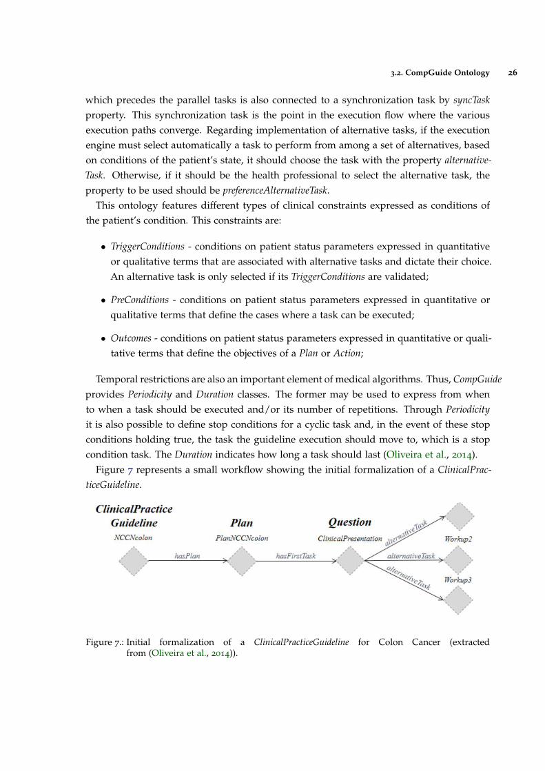
Temporal restrictions are also an important element of medical algorithms. Thus, CompGuideprovides Periodicity and Duration classes. The former may be used to express from whento when a task should be executed and/or its number of repetitions. Through Periodicityit is also possible to define stop conditions for a cyclic task and, in the event of these stopconditions holding true, the task the guideline execution should move to, which is a stopcondition task. The Duration indicates how long a task should last (Oliveira et al., 2014).
Figure 7 represents a small workflow showing the initial formalization of a ClinicalPrac-ticeGuideline.
Figure 7.: Initial formalization of a ClinicalPracticeGuideline for Colon Cancer (extractedfrom (Oliveira et al., 2014)).
3.3. OWL Structure 27
In comparison with other CIG models, CompGuide does not require any expertise inprogramming languages to define these conditions, unlike existing approaches. It alsoprovides greater expressiveness in the definition of tasks and controlling relationships.
3.3 owl structure
The OWL (Web Ontology Language) is designed for use by applications that need to processthe content of information instead of just presenting information to humans. OWL facil-itates greater machine interpretability of Web content than that supported by XML, RDF,and RDF Schema (RDF-S) by providing additional vocabulary along with a formal seman-tics (McGuinness et al., 2004). In other words, OWL is a language for defining ontologieson the Web. The Semantic Web is a vision for the future of the Web in which informationis given explicit meaning, making it easier for machines to automatically process and in-tegrate information available on the Web. The Semantic Web will build on XML’s abilityto define customized tagging schemes and RDF’s flexible approach to representing data.The first level above RDF required for the Semantic Web is an ontology language whatcan formally describe the meaning of terminology used in Web documents. If machinesare expected to perform useful reasoning tasks on these documents, the language must gobeyond the basic semantics of RDF Schema (Wang et al., 2004).
An OWL ontology describes a domain in terms of classes, properties and individualsand may include rich descriptions of the characteristics of those objects. OWL ontologiescan be used to describe the properties of Web resources. Where earlier representationlanguages have been used to develop tools and ontologies for specific user-communities inareas such as sciences, health and e-commerce, they were not necessarily designed to becompatible with the World Wide Web, or more specifically the Semantic Web, as is the casewith OWL. Features of OWL are a collection of expressive operators for concept descriptionincluding boolean operators (intersection, union and complement), plus explicit quantifiersfor properties and relationships; the ability to specify characteristics of properties, such astransitivity or domains and ranges (Bechhofer et al., 2004).
OWL can declare classes, and organize these classes in a subsumption (subclass) hierar-chy. OWL classes can be specified as logical combinations (intersections, unions, or com-plements) of other classes, or as enumerations of specified objects. OWL can also declareproperties, organize these properties into a sub-property hierarchy, and provide domainsand ranges for these properties. The domains of OWL properties are OWL classes, andranges can be either OWL classes or externally-defined datatypes such as string or integer.OWL can state that a property is transitive, symmetric, functional, or is the inverse of an-other property. OWL can express which objects (also called individuals) belong to whichclasses, and what the property values are of specific individuals. Equivalence statements
3.4. Domain Model 28
can be made on classes and on properties, disjointness statements can be made on classes,and equality and inequality can be asserted between individuals (Knublauch et al., 2004).
Also OWL provides restrictions on how properties behave that are local to a class. OWLcan define classes where a particular property is restricted so that all the values for theproperty in instances of the class must belong to a certain class (or datatype); at least onevalue must come from a certain class (or datatype); there must be at least certain specificvalues; and there must be at least or at most a certain number of distinct values (Knublauchet al., 2004).
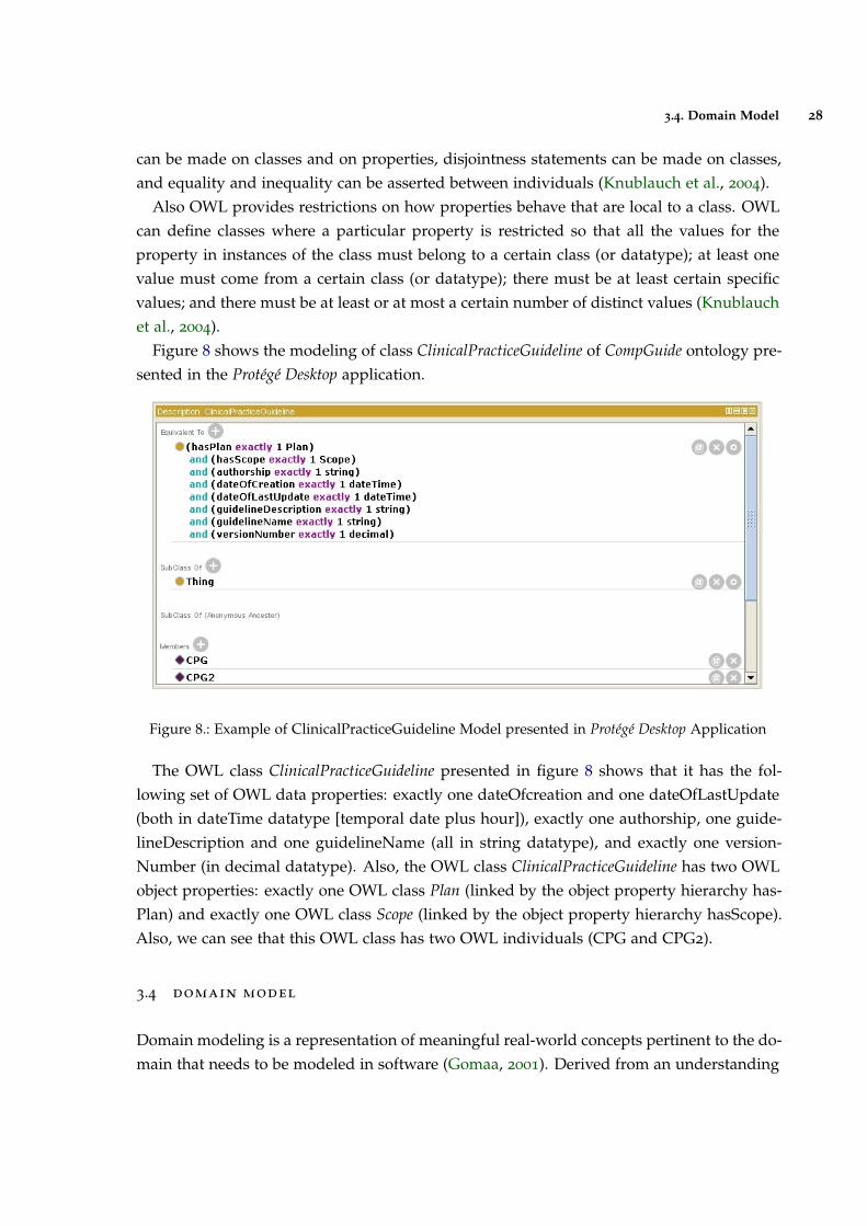
Figure 8 shows the modeling of class ClinicalPracticeGuideline of CompGuide ontology pre-sented in the Protégé Desktop application.
Figure 8.: Example of ClinicalPracticeGuideline Model presented in Protégé Desktop Application
The OWL class ClinicalPracticeGuideline presented in figure 8 shows that it has the fol-lowing set of OWL data properties: exactly one dateOfcreation and one dateOfLastUpdate(both in dateTime datatype [temporal date plus hour]), exactly one authorship, one guide-lineDescription and one guidelineName (all in string datatype), and exactly one version-Number (in decimal datatype). Also, the OWL class ClinicalPracticeGuideline has two OWLobject properties: exactly one OWL class Plan (linked by the object property hierarchy has-Plan) and exactly one OWL class Scope (linked by the object property hierarchy hasScope).Also, we can see that this OWL class has two OWL individuals (CPG and CPG2).
3.4 domain model
Domain modeling is a representation of meaningful real-world concepts pertinent to the do-main that needs to be modeled in software (Gomaa, 2001). Derived from an understanding
3.4. Domain Model 29
of system-level requirements, identifying domain entities and their relationships providesan effective basis for understanding and helps practitioners design systems for maintain-ability, testability, and incremental development. As a result, domain modeling envisionsthe solution as a set of domain objects that collaborate to fulfill system-level scenarios (Weiand Hong, 2003).
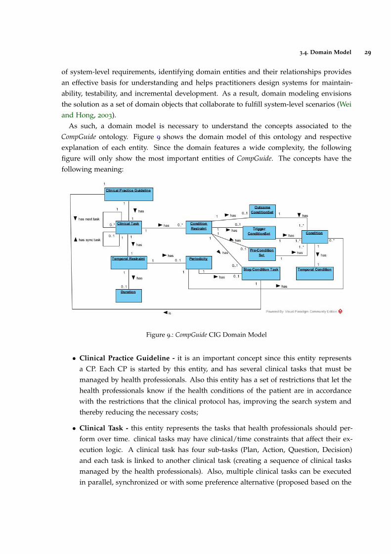
As such, a domain model is necessary to understand the concepts associated to theCompGuide ontology. Figure 9 shows the domain model of this ontology and respectiveexplanation of each entity. Since the domain features a wide complexity, the followingfigure will only show the most important entities of CompGuide. The concepts have thefollowing meaning:
Figure 9.: CompGuide CIG Domain Model
• Clinical Practice Guideline - it is an important concept since this entity representsa CP. Each CP is started by this entity, and has several clinical tasks that must bemanaged by health professionals. Also this entity has a set of restrictions that let thehealth professionals know if the health conditions of the patient are in accordancewith the restrictions that the clinical protocol has, improving the search system andthereby reducing the necessary costs;
• Clinical Task - this entity represents the tasks that health professionals should per-form over time. clinical tasks may have clinical/time constraints that affect their ex-ecution logic. A clinical task has four sub-tasks (Plan, Action, Question, Decision)and each task is linked to another clinical task (creating a sequence of clinical tasksmanaged by the health professionals). Also, multiple clinical tasks can be executedin parallel, synchronized or with some preference alternative (proposed based on the
3.4. Domain Model 30
clinical constraints and the patient health condition). Each clinical task can have mul-tiple stop conditions (based on health conditions or timed tasks), allowing a bettercontrol/performance in the execution of the task;
• Condition Restraint - this entity specifies a set of selected conditions which verify thehealth conditions of a patient and the CIG scenario. The scenarios allow a physicianto synchronize the management of a patient with the corresponding parts of a guideand are normally used as information entry points;
• Outcome ConditionSet - this entity specifies the set of health conditions a patientwill have after the clinical task is completed;
• Trigger ConditionSet - this entity specifies the set of health conditions a patient musthave in order to apply the current clinical task;
• Pre-ConditionSet - this entity specifies the set of health conditions a patient musthave before going through this clinical task;
• Stop Condition Task - this entity allows for the application of a synchronized entry,where the current clinical task is paused when the defined Stop Condition Task isbeing applied;
• Temporal Restraint - this entity specifies the set of structures related to time con-straints implemented into clinical tasks. The use of this entity allows the temporalsynchronization of clinical tasks to be performed in a CP;
• Periodicity - represents the execution cycle of a clinical task, allowing a repetitionpattern to be executed. Also, stop conditions can be applied to the periodicity inorder to halt this cycle and follow to the next clinical task. Periodicity is an entity thatcan be applied in the Plan and Action clinical tasks;
• Duration - this entity is used to limit the duration/time that a clinical task is expectedto last. In other words, it is a time restriction that can be applied to a clinical task.Duration is an entity that can be applied in the Plan and Action clinical tasks;
• Condition - this entity allows to compare the pre-defined values stated in the CIGand the values examined in the patient. The results of this comparison will assist inchoosing the next clinical task;
• Temporal Condition - this entity may be implemented within a condition, allowingto add temporal restrictions into conditions;
Other important entities which need to be described but not shown in this figure:
3.5. System Actors 31
• Clinical Actions - this entity models tasks that must be performed in an Action clin-ical task. In other words, it allows to identify the action that must be executed inan Action clinical task. Three types of tasks are defined: medical actions, activity tar-geted actions (such as sending messages or obtaining patient data) and control actions(invoking structures as sub-tabs or macros that allow recursion);
• Parameter - this entity is used in the Question clinical tasks, and it aims to define thecharacteristics of the issue inspected in the patient health status. As such, it allowsto identify the health parameters of the patient, which are needed to select the nextviable clinical task. This is a very important entity, since it’s used to identify/selectthe next Clinical step in the AIM system;
• Option - this entity is used in the Decision clinical tasks, and sets the number of op-tions that a clinical professional can select to make a decision. This entity is neededsince justified changes occur due to differences in health systems, differences in pop-ulation characteristics, or due to patient preferences or professional, in case there aremore than a scientifically valid option;
3.5 system actors
An actor is a behaviored classifier which specifies a role played by an external entity thatinteracts with the subject (for example, by exchanging signals and data), a human user ofthe designed system, some other system or hardware using services of the subject.
The term role is used informally as some type, group or particular facet of users thatrequires specific services from the subject modeled with associated use cases. When anexternal entity interacts with the subject, it plays the role of a specific actor. That singlephysical entity may play several different roles, and a specific role may be played by singleor multiple different instances (Boggs and Boggs, 2002).
In this project there are two types of users: Health Professionals and Administrator. Gen-erally speaking, the actors are the elements that will interact with the system. These actorsare represented as important elements in the system operating mechanism.
3.5.1 Administrator
This user is responsible for managing all the files saved in the repository. The administrator(or admin) has the responsibility to maintain the latest CIG version in the repository (down-loaded and used by the health professionals), check the modified versions sent by healthprofessionals, and check the feedback from users, creating, if necessary, changes that willpositively influence the use of this plug-in.
3.6. Requirement Analysis 32
3.5.2 Health Professionals
These users are responsible for managing the set of CIGs, allowing the creation, modifica-tion or deletion of clinical steps or aspects in the CompGuide ontology file. Through theuse of a simplified step-by-step process (Wizard method inserted into the plug-in), healthprofessionals are able to approach CP medical knowledge into the CIG data.
Also, health professionals have access to graphical display features of the CompGuideontology, which can be used to more easily understand the data structure of the CIG.
Since the plug-in is connected to a repository, health professionals can download the lat-est version of the CompGuide ontology, or share their modified CIG version to the CompGuidedevelopment team. A requirement for these functionalities is a stable connection to the In-ternet for them to work. The remaining functionalities are managed locally.
3.6 requirement analysis
The process of gathering software requirements from the client, analyzing and documentingthem is known as requirement analysis (Van Lamsweerde, 2009). These processes encom-pass those tasks that go into determining the needs or conditions to meet for a new oraltered product, taking into account possibly conflicting requirements of the various stake-holders, such as beneficiaries or users. Requirement analysis is critical to the success ofa development project. Requirements must be actionable, measurable, testable, related toidentified business needs or opportunities, and defined to a level of detail sufficient forsystem design (Pohl, 2010).
The goal of requirement engineering is to develop and maintain a sophisticated anddescriptive system requirements specification document. Requirements can be functionaland non-functional.
3.6.1 Functional Requirements
Functional requirements describe the features the system has available, explained in a com-plete and consistent manner. In other words, functional requirements should include func-tions performed by specific screens, outlines of workflows performed by the system, andother business or compliance requirements the system must meet (Wiegers, 2003).
The next list represents the set of features that are available when using the CompGuideEditor plug-in:
• Allow the user to access all functionalities of Protégé Desktop 4.X application;
3.6. Requirement Analysis 33
• Allow the user to include features of other plug-ins (restricted to application ProtégéDesktop 4.X) in the CompGuide Editor plug-in, in a simple and quick way, and withoutthe need for programming knowledge;
• Allow access to all the reasoner features of Protégé Desktop 4.X. Protégé reasoners areresponsible for the verification and validation of the created individuals associatedwith the structure of the ontology classes and restrictions;
• Allow the user to create, edit, or delete individuals in CompGuide ontology througha step-by-step Wizard system while respecting the basic structures of classes andrestrictions;
• Allow the user to download the latest versions of the OWL file CompGuide ontology,through the CompGuide Editor plug-in or by visiting the Git CompGuide repository;
• Allow the sharing of versions modified by users to CompGuide development team, ina safe and simple way;
• Allow the display of information (represented by a list and dynamic 2D graphic) ofany part of the CompGuide ontology;
• In the graphical representation, allow the user to filter structures (classes, individuals,data property stored in individual, associations, etc.);
• In the graphical representation, allow the user to drag the nodes (representing class-es/individuals) to the positions that the user wants, allowing to store this representa-tion in image files (PNG, GIF or JPEG format);
• Allow the administrator to manage CompGuide ontology versions available in therepository (via Git);
• Allow the administrator to receive the OWL files (restricted only to the CIG CompGuideontological file) associated with a short description of the changes made by the user;
3.6.2 Non-Functional Requirements
Non-functional requirements (or system qualities) describe terms related to the security, reli-ability, maintainability, scalability, usability and technologies involved in the system (Chunget al., 2012).
These requirements are persistent qualities and constraints that ensure the usability andefficacy of the entire system. Failing to meet any one of them result in systems that do notmeet internal business, user, or market needs (Young, 2001).
3.6. Requirement Analysis 34
The next list represents the set of system qualities that are available when using theCompGuide Editor plug-in:
• Adaptation: provide a plug-in for Protégé Desktop 4.X application that can be inte-grated with its features, along with the features of other plug-ins;
• Free Access: development and implementation of the plug-in by only using free tech-nologies (Protégé Desktop 4.X, Java Development Kit 1.8 and Ant Compiler);
• Interface Organization: Protégé Desktop 4.X application should allow the re-organizationof the models of the interface without the need for additional programming knowl-edge, in a quick and easy way;
• Presentation: CompGuide Editor plug-in provides an appealing, interactive, simpleand easy handling;
• Learning Time: users should know how to use the system in a short time;
• Scalability: the system should be able to maintain the same performance (responsetime) when there is an increase of information (more stored individuals in ontolog-ical file) and / or when multiple simultaneous requests are requested to the cloudrepository;
• Standardization: the Wizard presentation should follow a standard step-by-step pro-cess (making it less confusing for the user to interpret the features of the plug-in);
• Performance: The system should process any event in a given time;
• Security: all data communication features involve only the CIG files associated withthe CompGuide ontology, making it impossible to send any other files that are notassociated with the plug-in solution;
• Allocated Space Management: all data communication features keep a care in thefile space allocation, compressing all data sent/ decompressing all data received bythe plug-in, reducing the connectivity and file management requirements;
• Portability: the solution should run on most computer platforms (provided there is aProtégé 4.X version available to be installed on that platform);
• Communication: the solution must include the ability to share or access CompGuideCIGs available in the repository;
• Ethical Requirements: the system should not use the user information for externalcommercial purposes;
• Organization: keep all managed files by the plug-in in an organized and easy mannerto interpret (easier access);

3.7. Use Cases 35
3.7 use cases
Use cases is a list of actions or event steps, typically defining the interactions between arole (known in the Unified Modeling Language as an actor) and a system, to achieve a goal.The actor can be a human or other external system (Jacobson et al., 2011). In other words, ause case is a series of related interactions between a user (or more generally, an actor) anda system that enables the user to achieve a goal (Bittner, 2002). Yet use case diagrams neverdescribes how they are implemented. These can be imagined as a black box where only theinput, output and the function of the black box is known.
The purposes of use case diagrams can be as follows:
• Used to gather requirements of a system;
• Used to get an outside view of a system;
• Identify external and internal factors influencing the system;
• Show the interacting among the requirements are actors;
Use case analysis is an important and valuable requirement analysis technique that hasbeen widely used in modern software engineering, making it one of the best ways to capturefunctional requirements of a system. (Cockburn, 2008).
Next the different interactions between the users and the system will be shown.
3.7.1 Use Cases Diagram
There are five types of relationships in a use case diagram (Bittner, 2002). They are:
• Association between an actor and a use case;
• Generalization of an actor;
• Extend relationship between two use cases;
• Include relationship between two use cases;
• Generalization of a use case;
As such, figure 10 show the use cases diagram of this system.
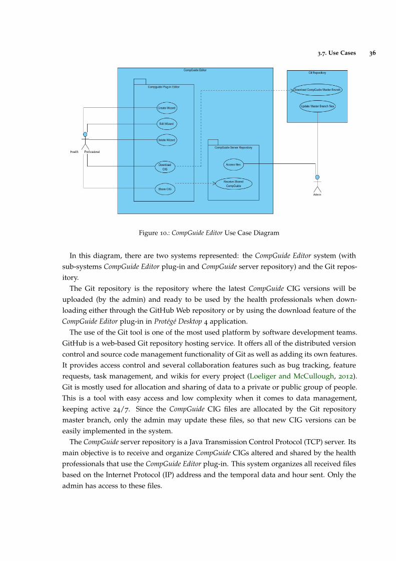
3.7. Use Cases 36
Figure 10.: CompGuide Editor Use Case Diagram
In this diagram, there are two systems represented: the CompGuide Editor system (withsub-systems CompGuide Editor plug-in and CompGuide server repository) and the Git repos-itory.
The Git repository is the repository where the latest CompGuide CIG versions will beuploaded (by the admin) and ready to be used by the health professionals when down-loading either through the GitHub Web repository or by using the download feature of theCompGuide Editor plug-in in Protégé Desktop 4 application.
The use of the Git tool is one of the most used platform by software development teams.GitHub is a web-based Git repository hosting service. It offers all of the distributed versioncontrol and source code management functionality of Git as well as adding its own features.It provides access control and several collaboration features such as bug tracking, featurerequests, task management, and wikis for every project (Loeliger and McCullough, 2012).Git is mostly used for allocation and sharing of data to a private or public group of people.This is a tool with easy access and low complexity when it comes to data management,keeping active 24/7. Since the CompGuide CIG files are allocated by the Git repositorymaster branch, only the admin may update these files, so that new CIG versions can beeasily implemented in the system.
The CompGuide server repository is a Java Transmission Control Protocol (TCP) server. Itsmain objective is to receive and organize CompGuide CIGs altered and shared by the healthprofessionals that use the CompGuide Editor plug-in. This system organizes all received filesbased on the Internet Protocol (IP) address and the temporal data and hour sent. Only theadmin has access to these files.

3.7. Use Cases 37
CompGuide Editor plug-in was made to work in Protégé Desktop 4 application. In thefigure, the download CIG feature is dependent on the Git repository server status andshare CIG feature is dependent on the CompGuide server repository status. As such, if theseservers are offline, a message will appear, informing the user that the connection couldn’t beestablished. The Create Wizard, Edit Wizard and Delete Wizard are the features designedto manage the CompGuide CIG individuals. Since these are made locally, these features areonly enabled if the CompGuide ontology is loaded in the Protégé Desktop 4 application.
3.7.2 Description of Use Cases
The Description of Use Cases allows to know what the end user wants to achieve by firstidentifying their problem. Once the problems are found, solutions can start to be looked.This process allows to outline the interactions between actor and system in solving a prob-lem as described under a system situation. This tool can be used to find out the desiredsystem behavior with its user.
The Description of Use Cases constitutes an high level user-and-system conversation,which aims to find out the intents or actions of actors and how the system reacts to thoseactor inputs. The description should be concise when deciding what to include in theevents flow. This analysis is aimed to identify requirements from an end user point of view.Implementation details can, however, be modeled with Unified Modelling Language (UML)sequence diagram in form of sub-diagram of user stories.
Tables 2, 3, 4, 5, 6, 7, 8 and 9 in Annex A show the description of the use cases diagram.
3.8. Discussion and Analysis 38
3.8 discussion and analysis
Studying the entities defined in the domain model, by investigating and analyzing the func-tional and non-functional requirements of the system along with the verification of the usecase diagrams, it was possible to have a working basis, on which the problem in ques-tion can be identified, and the set of features that the system must provide to solve them.Through this chapter, we can see that a CP is a representation of a set of interrelated tasks,which apply restrictions/conditions related to the patient status or to temporal restrictions.The use of the CIG CompGuide is one of the CP forms that allow the automatic execution ofa linked tasks network model, used by clinical artificial intelligent systems.
Therefore, the use of CompGuide ontology allows the display of information on the dif-ferent clinical tasks to be performed, becoming a personal assistant to enable health profes-sionals manage the clinical status of the patients in a faster, simpler, and more cost effectiveway.
The creation of CompGuide Editor plug-in will keep this ontology updated with the lat-est clinical protocol details, specifically the procedures/clinical tasks applied in currentmedicine. These details are implemented in a wizard / step-by-step model, eliminatingthe need for health professionals to have any knowledge about the Protégé Desktop features,and greatly reducing the amount of time required to implement changes in the CIG. Theincluded data sharing features are an added value to easy access to the CIG files, both byhealth professionals and by CompGuide development team.
4
I M P L E M E N TAT I O N I N P R O T É G É D E S K T O P
This chapter is intended to describe the set of planned steps taken in developing a toolable to create/edit CIGs CompGuide, in a quick and simple way. As such, an explanationis needed about how the idea was born, the platform used, its programming language, itsadvantages and limitations, the external plug-ins and Java API used, its features, and aconcise presentation.
The following sub-chapters show the data structure of the application, its main featuresand restrictions, some diagrams and models explaining how the application features areexecuted and relating the data structure and the functions used, the appearance of the CIGtool plug-in.
In the end, there will be a solution analysis, discussing about the key aspects and diffi-culties found in the development of this tool.
4.1 technologies and tools used
The idea of creating a Protégé Desktop plug-in emerged from the need to create softwarecapable of implementing all the features offered by Protégé Desktop application (specificallythe functionality of managing the data of an ontology through the use of a graphical inter-face) along with the creation of new features capable of resolving the problems of a project.Another advantage that came from using this application was the ability to implement extrafeatures from other plug-ins without the need of any programming knowledge required,in a quick, easy and simple way. In addition, Protégé Desktop application presents an enor-mous active community that is constantly updating its functionalities. All these points leadto the conclusion that the creation of a plug-in for the Protégé Desktop application would bean asset in solving the proposed problem.
Since Protégé Desktop application is a tool programmed in Java, it was taken into accountthe advantages of creating a plug-in in this programming language. The following listshows the set of advantages in using this platform (Gosling and Mcgilton, 1996):
39
4.2. Software Architecture 40
• Java is currently one of the most used programming languages around the world, andstill growing in enterprises, through new adoptions;
• In addition to being a programming language, it’s also a development platform;
• Portability: It is possible to develop desktop, mobile, card, web, digital TV, and otherapplications. In other words, this language tends to be widely developed mainly formobile, web and cloud computing;
• Community: Java user groups are very strong in the whole world. By exploringthe internet, anyone has easy access to programming material, ways to participatein regional meetings, lectures and even short courses. There is also an ease to solveprogramming problems, thanks to the exchange of ideas in forums or chats;
• Frameworks: Thanks to the investment of this community and some enterprises, thereis now a variety of frameworks to facilitate the work of the developer;
• Programming Adaptability: The Java virtual machine currently runs about 350 lan-guages, such as Groovy dynamic language, JPython, Python, JRuby, Ruby, etc.;
• Operational Systems: When a Java file is compiled, it generates a new file that can beinterpreted in any Java Virtual Machine (JVM). As long as the operating system has aJVM, the Java project can be run on any of these systems (Windows, GNU / Linux orMac);
• Evolution: Java tends to be developed for technologies that integrate HTML5. Thisoccurs because new Java applications have the need to focus on Web and mobilearchitectures;
4.2 software architecture
Currently, the most used versions of Protégé vary between versions 3, 4 and 5, being 3 theoldest and 5 the newest. Since version 3 is the oldest, it is also the version with the greaternumber of plug-ins created for the application, which are incompatible with versions 4
and 51. As such, the selected version of the Protégé Desktop application was version 4,
since CompGuide ontology was created using this release (Protégé Desktop 3 uses OWL API1 while Protégé Desktop 4 uses OWL API 2) (Rubin et al., 2007). Because of compatibilityissues, the plug-in should be created for Protégé Desktop 4 application. However, throughsome studies in the Protégé Desktop support forums2, we can conclude that the compatibilityissues only arise between older versions of the application (for example, an ontology created
1 http://protegewiki.stanford.edu/wiki/Protege_Plugin_Library
2 http://protege-project.136.n4.nabble.com/Protege-OWL-4-x-Support-f21363.html
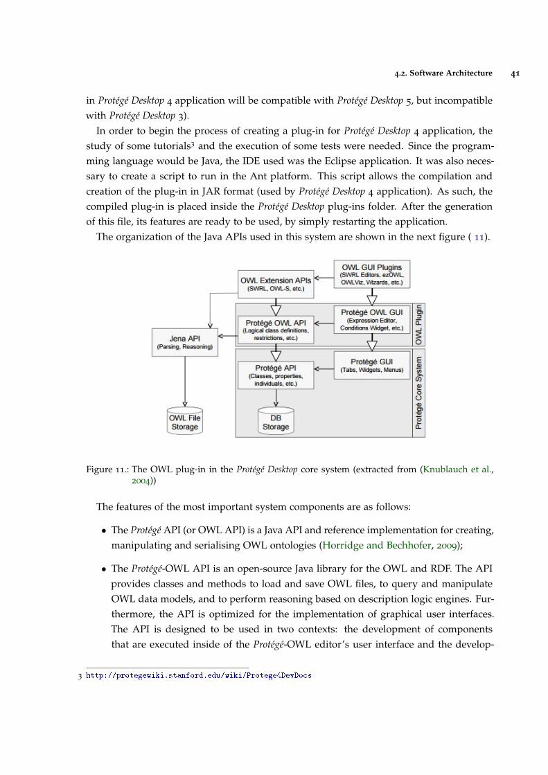
4.2. Software Architecture 41
in Protégé Desktop 4 application will be compatible with Protégé Desktop 5, but incompatiblewith Protégé Desktop 3).
In order to begin the process of creating a plug-in for Protégé Desktop 4 application, thestudy of some tutorials3 and the execution of some tests were needed. Since the program-ming language would be Java, the IDE used was the Eclipse application. It was also neces-sary to create a script to run in the Ant platform. This script allows the compilation andcreation of the plug-in in JAR format (used by Protégé Desktop 4 application). As such, thecompiled plug-in is placed inside the Protégé Desktop plug-ins folder. After the generationof this file, its features are ready to be used, by simply restarting the application.
The organization of the Java APIs used in this system are shown in the next figure ( 11).
Figure 11.: The OWL plug-in in the Protégé Desktop core system (extracted from (Knublauch et al.,2004))
The features of the most important system components are as follows:
• The Protégé API (or OWL API) is a Java API and reference implementation for creating,manipulating and serialising OWL ontologies (Horridge and Bechhofer, 2009);
• The Protégé-OWL API is an open-source Java library for the OWL and RDF. The APIprovides classes and methods to load and save OWL files, to query and manipulateOWL data models, and to perform reasoning based on description logic engines. Fur-thermore, the API is optimized for the implementation of graphical user interfaces.The API is designed to be used in two contexts: the development of componentsthat are executed inside of the Protégé-OWL editor’s user interface and the develop-
3 http://protegewiki.stanford.edu/wiki/Protege4DevDocs
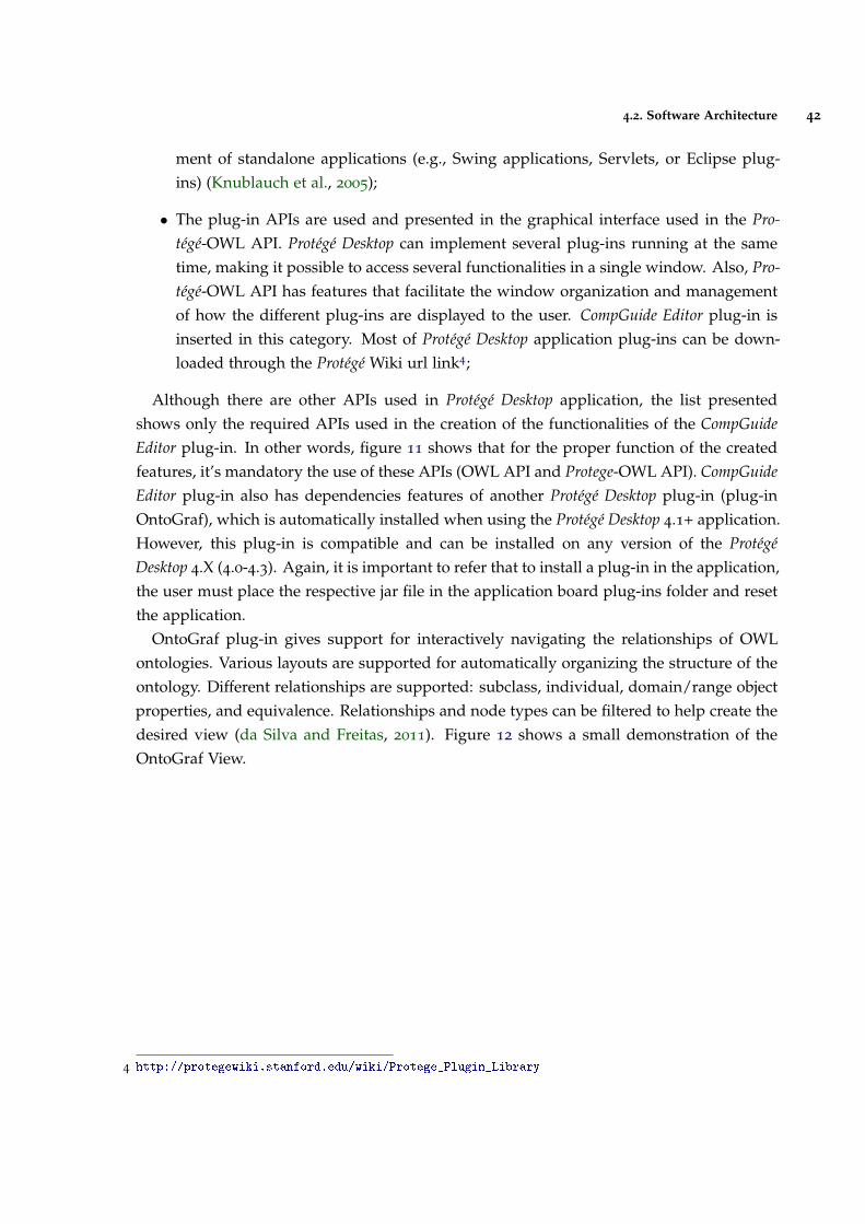
4.2. Software Architecture 42
ment of standalone applications (e.g., Swing applications, Servlets, or Eclipse plug-ins) (Knublauch et al., 2005);
• The plug-in APIs are used and presented in the graphical interface used in the Pro-tégé-OWL API. Protégé Desktop can implement several plug-ins running at the sametime, making it possible to access several functionalities in a single window. Also, Pro-tégé-OWL API has features that facilitate the window organization and managementof how the different plug-ins are displayed to the user. CompGuide Editor plug-in isinserted in this category. Most of Protégé Desktop application plug-ins can be down-loaded through the Protégé Wiki url link4;
Although there are other APIs used in Protégé Desktop application, the list presentedshows only the required APIs used in the creation of the functionalities of the CompGuideEditor plug-in. In other words, figure 11 shows that for the proper function of the createdfeatures, it’s mandatory the use of these APIs (OWL API and Protege-OWL API). CompGuideEditor plug-in also has dependencies features of another Protégé Desktop plug-in (plug-inOntoGraf), which is automatically installed when using the Protégé Desktop 4.1+ application.However, this plug-in is compatible and can be installed on any version of the ProtégéDesktop 4.X (4.0-4.3). Again, it is important to refer that to install a plug-in in the application,the user must place the respective jar file in the application board plug-ins folder and resetthe application.
OntoGraf plug-in gives support for interactively navigating the relationships of OWLontologies. Various layouts are supported for automatically organizing the structure of theontology. Different relationships are supported: subclass, individual, domain/range objectproperties, and equivalence. Relationships and node types can be filtered to help create thedesired view (da Silva and Freitas, 2011). Figure 12 shows a small demonstration of theOntoGraf View.
4 http://protegewiki.stanford.edu/wiki/Protege_Plugin_Library
4.2. Software Architecture 43
Figure 12.: OntoGraf plug-in in Protégé Desktop application(extracted from OntoGraf Wiki url5).
Later in the plug-in interface features, all CompGuide Editor plug-in features will be prop-erly shown and explained.
So far we have explained the methodologies used in solving the ontological data manage-ment problem. Now we will make the point analysis on the data management via cloud(one of the other objectives in the creation of this plug-in). One of the ideas that came tosolve this problem would be the sharing data by using one of the most popular platformsin group development: the Git platform.
Git is an open source project that is by far, the most widely used modern version controlsystem in the world today. Git is a mature, actively maintained project that is an example ofa Distributed Version Control System(DVCS). Rather than have only one single place for thefull version history of the software as is common in once-popular version control systemslike CVS or Subversion (also known as SVN), in Git, every developer’s working copy ofthe code is also a repository that can contain the full history of all changes. In additionto being distributed, Git has been designed with performance, security and flexibility inmind (Gandrud, 2013).
Git proposes a solution in the contribution of solving an open source project. Let’s say,for example, if you wanted to contribute to an open source project you had to manuallydownload the project’s source code, make your changes locally, create a list of changescalled a patch and then e-mail the patch to the project’s maintainer. The maintainer would
5 http://protegewiki.stanford.edu/wiki/OntoGraf
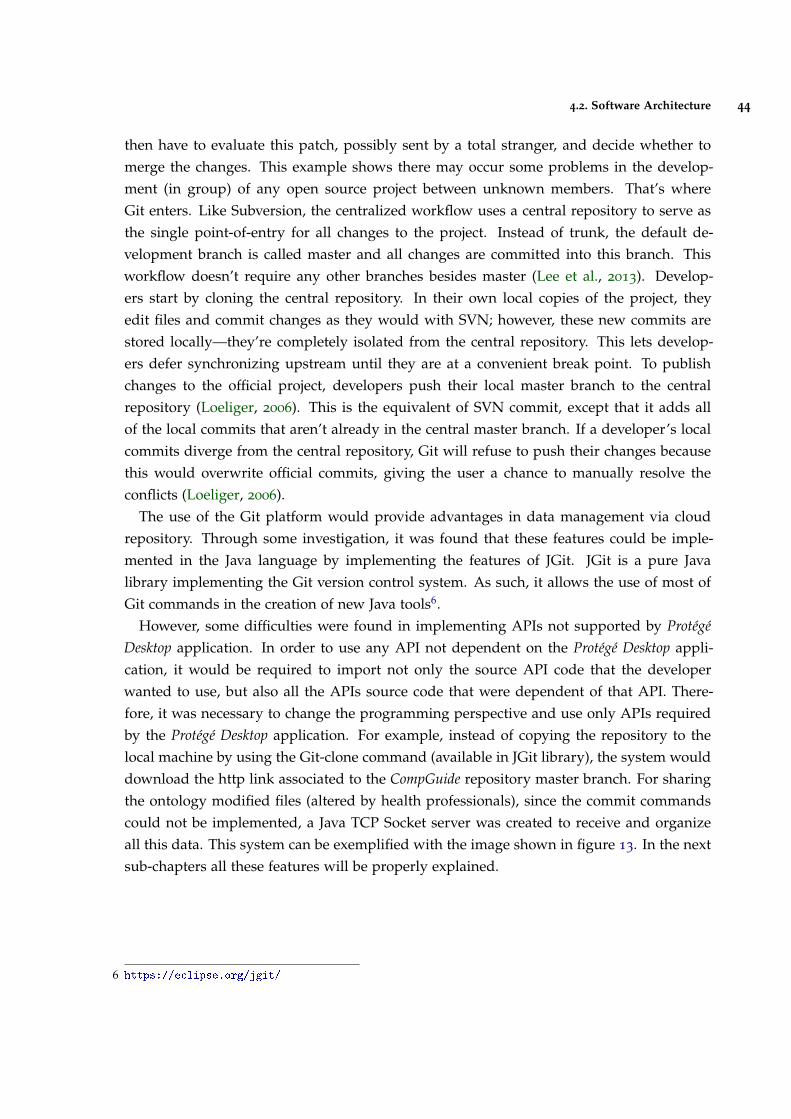
4.2. Software Architecture 44
then have to evaluate this patch, possibly sent by a total stranger, and decide whether tomerge the changes. This example shows there may occur some problems in the develop-ment (in group) of any open source project between unknown members. That’s whereGit enters. Like Subversion, the centralized workflow uses a central repository to serve asthe single point-of-entry for all changes to the project. Instead of trunk, the default de-velopment branch is called master and all changes are committed into this branch. Thisworkflow doesn’t require any other branches besides master (Lee et al., 2013). Develop-ers start by cloning the central repository. In their own local copies of the project, theyedit files and commit changes as they would with SVN; however, these new commits arestored locally—they’re completely isolated from the central repository. This lets develop-ers defer synchronizing upstream until they are at a convenient break point. To publishchanges to the official project, developers push their local master branch to the centralrepository (Loeliger, 2006). This is the equivalent of SVN commit, except that it adds allof the local commits that aren’t already in the central master branch. If a developer’s localcommits diverge from the central repository, Git will refuse to push their changes becausethis would overwrite official commits, giving the user a chance to manually resolve theconflicts (Loeliger, 2006).
The use of the Git platform would provide advantages in data management via cloudrepository. Through some investigation, it was found that these features could be imple-mented in the Java language by implementing the features of JGit. JGit is a pure Javalibrary implementing the Git version control system. As such, it allows the use of most ofGit commands in the creation of new Java tools6.
However, some difficulties were found in implementing APIs not supported by ProtégéDesktop application. In order to use any API not dependent on the Protégé Desktop appli-cation, it would be required to import not only the source API code that the developerwanted to use, but also all the APIs source code that were dependent of that API. There-fore, it was necessary to change the programming perspective and use only APIs requiredby the Protégé Desktop application. For example, instead of copying the repository to thelocal machine by using the Git-clone command (available in JGit library), the system woulddownload the http link associated to the CompGuide repository master branch. For sharingthe ontology modified files (altered by health professionals), since the commit commandscould not be implemented, a Java TCP Socket server was created to receive and organizeall this data. This system can be exemplified with the image shown in figure 13. In the nextsub-chapters all these features will be properly explained.
6 https://eclipse.org/jgit/
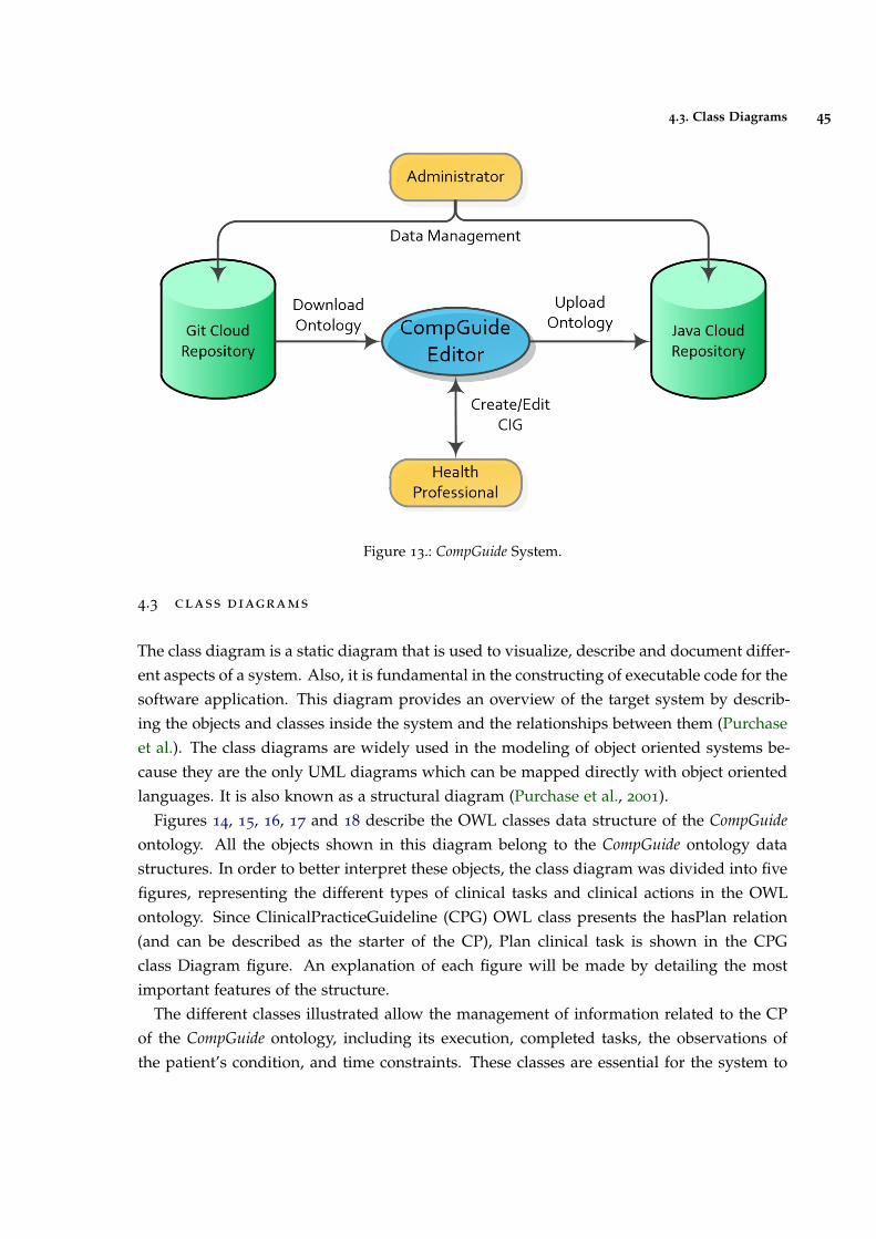
4.3. Class Diagrams 45
Figure 13.: CompGuide System.
4.3 class diagrams
The class diagram is a static diagram that is used to visualize, describe and document differ-ent aspects of a system. Also, it is fundamental in the constructing of executable code for thesoftware application. This diagram provides an overview of the target system by describ-ing the objects and classes inside the system and the relationships between them (Purchaseet al.). The class diagrams are widely used in the modeling of object oriented systems be-cause they are the only UML diagrams which can be mapped directly with object orientedlanguages. It is also known as a structural diagram (Purchase et al., 2001).
Figures 14, 15, 16, 17 and 18 describe the OWL classes data structure of the CompGuideontology. All the objects shown in this diagram belong to the CompGuide ontology datastructures. In order to better interpret these objects, the class diagram was divided into fivefigures, representing the different types of clinical tasks and clinical actions in the OWLontology. Since ClinicalPracticeGuideline (CPG) OWL class presents the hasPlan relation(and can be described as the starter of the CP), Plan clinical task is shown in the CPGclass Diagram figure. An explanation of each figure will be made by detailing the mostimportant features of the structure.
The different classes illustrated allow the management of information related to the CPof the CompGuide ontology, including its execution, completed tasks, the observations ofthe patient’s condition, and time constraints. These classes are essential for the system to
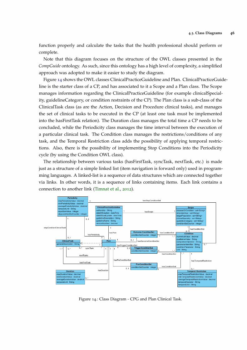
4.3. Class Diagrams 46
function properly and calculate the tasks that the health professional should perform orcomplete.
Note that this diagram focuses on the structure of the OWL classes presented in theCompGuide ontology. As such, since this ontology has a high level of complexity, a simplifiedapproach was adopted to make it easier to study the diagram.
Figure 14 shows the OWL classes ClinicalPracticeGuideline and Plan. ClinicalPracticeGuide-line is the starter class of a CP, and has associated to it a Scope and a Plan class. The Scopemanages information regarding the ClinicalPracticeGuideline (for example clinicalSpecial-ity, guidelineCategory, or condition restraints of the CP). The Plan class is a sub-class of theClinicalTask class (as are the Action, Decision and Procedure clinical tasks), and managesthe set of clinical tasks to be executed in the CP (at least one task must be implementedinto the hasFirstTask relation). The Duration class manages the total time a CP needs to beconcluded, while the Periodicity class manages the time interval between the execution ofa particular clinical task. The Condition class manages the restrictions/conditions of anytask, and the Temporal Restriction class adds the possibility of applying temporal restric-tions. Also, there is the possibility of implementing Stop Conditions into the Periodicitycycle (by using the Condition OWL class).
The relationship between various tasks (hasFirstTask, syncTask, nextTask, etc.) is madejust as a structure of a simple linked list (item navigation is forward only) used in program-ming languages. A linked-list is a sequence of data structures which are connected togethervia links. In other words, it is a sequence of links containing items. Each link contains aconnection to another link (Timnat et al., 2012).
Figure 14.: Class Diagram - CPG and Plan Clinical Task.
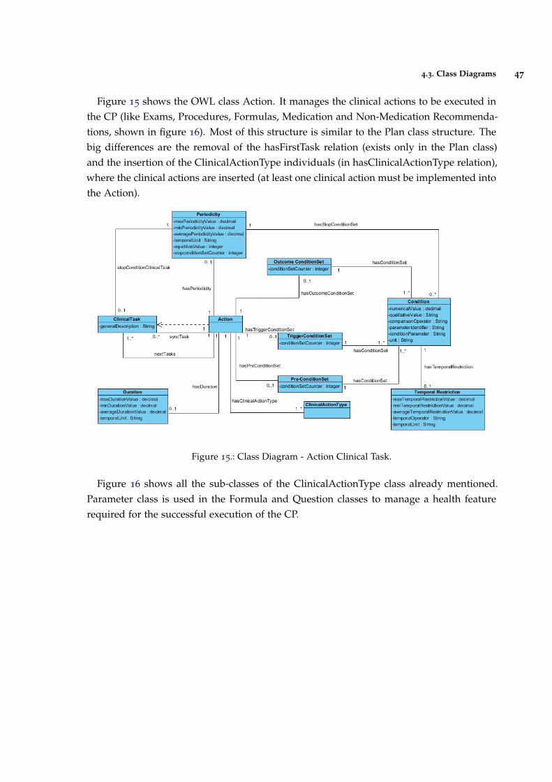
4.3. Class Diagrams 47
Figure 15 shows the OWL class Action. It manages the clinical actions to be executed inthe CP (like Exams, Procedures, Formulas, Medication and Non-Medication Recommenda-tions, shown in figure 16). Most of this structure is similar to the Plan class structure. Thebig differences are the removal of the hasFirstTask relation (exists only in the Plan class)and the insertion of the ClinicalActionType individuals (in hasClinicalActionType relation),where the clinical actions are inserted (at least one clinical action must be implemented intothe Action).
Figure 15.: Class Diagram - Action Clinical Task.
Figure 16 shows all the sub-classes of the ClinicalActionType class already mentioned.Parameter class is used in the Formula and Question classes to manage a health featurerequired for the successful execution of the CP.
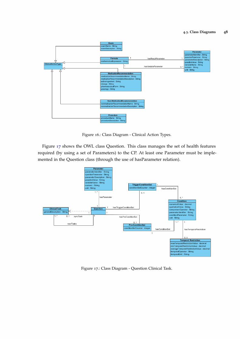
4.3. Class Diagrams 48
Figure 16.: Class Diagram - Clinical Action Types.
Figure 17 shows the OWL class Question. This class manages the set of health featuresrequired (by using a set of Parameters) to the CP. At least one Parameter must be imple-mented in the Question class (through the use of hasParameter relation).
Figure 17.: Class Diagram - Question Clinical Task.
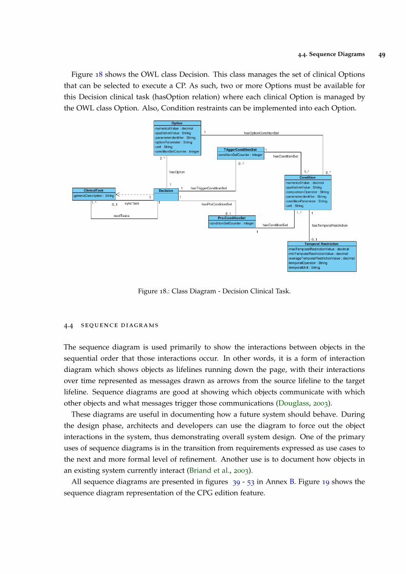
4.4. Sequence Diagrams 49
Figure 18 shows the OWL class Decision. This class manages the set of clinical Optionsthat can be selected to execute a CP. As such, two or more Options must be available forthis Decision clinical task (hasOption relation) where each clinical Option is managed bythe OWL class Option. Also, Condition restraints can be implemented into each Option.
Figure 18.: Class Diagram - Decision Clinical Task.
4.4 sequence diagrams
The sequence diagram is used primarily to show the interactions between objects in thesequential order that those interactions occur. In other words, it is a form of interactiondiagram which shows objects as lifelines running down the page, with their interactionsover time represented as messages drawn as arrows from the source lifeline to the targetlifeline. Sequence diagrams are good at showing which objects communicate with whichother objects and what messages trigger those communications (Douglass, 2003).
These diagrams are useful in documenting how a future system should behave. Duringthe design phase, architects and developers can use the diagram to force out the objectinteractions in the system, thus demonstrating overall system design. One of the primaryuses of sequence diagrams is in the transition from requirements expressed as use cases tothe next and more formal level of refinement. Another use is to document how objects inan existing system currently interact (Briand et al., 2003).
All sequence diagrams are presented in figures 39 - 53 in Annex B. Figure 19 shows thesequence diagram representation of the CPG edition feature.
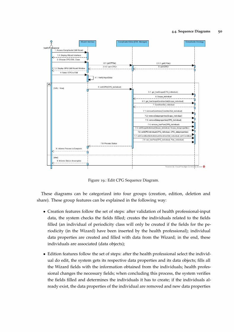
4.4. Sequence Diagrams 50
Figure 19.: Edit CPG Sequence Diagram.
These diagrams can be categorized into four groups (creation, edition, deletion andshare). These group features can be explained in the following way:
• Creation features follow the set of steps: after validation of health professional-inputdata, the system checks the fields filled; creates the individuals related to the fieldsfilled (an individual of periodicity class will only be created if the fields for the pe-riodicity (in the Wizard) have been inserted by the health professional); individualdata properties are created and filled with data from the Wizard; in the end, theseindividuals are associated (data objects);
• Edition features follow the set of steps: after the health professional select the individ-ual do edit, the system gets its respective data properties and its data objects; fills allthe Wizard fields with the information obtained from the individuals; health profes-sional changes the necessary fields; when concluding this process, the system verifiesthe fields filled and determines the individuals it has to create; if the individuals al-ready exist, the data properties of the individual are removed and new data properties
4.5. Plug-in Interface 51
are inserted, else new individuals are created with the necessary data properties. Ifthere are individuals which shouldn’t exist (based on the filled Wizard fields), theseindividuals are deleted;
• In delete features, after the health professional selects the individuals to delete, aloop is executed, deleting the respective individuals and it’s data objects associated.For example, if the CPG creation feature handles the creation of CPG and Scopeindividuals, the CPG delete feature will remove the CPG and Scope individuals. Allother delete features follow the same example;
• Download and share ontology features are dependent of the status of the connectionbetween the system and the respective cloud repositories. Since it is intended thatthe amount of data to send / receive is as low as possible, all data managed in thesefeatures are compressed. When concluding the download, the system handles thedecompression of the respective files;
4.5 plug-in interface
This sub-chapter presents the plug-in interface and clarifies the features implemented.Figure 20 shows the initial interface when opening the Protégé Desktop application. This
interface displays a set of menus at the top of the window, along with a set of Tabs. Throughthese Tabs, the user has the possibility of positioning and managing the set of plug-ins(and corresponding functionalities). Another important element shown in this figure is theontology IRI. Ontologies and their elements are identified using Internationalized ResourceIdentifiers (IRIs). Each ontology may have an ontology IRI, which is used to identify anontology. If an ontology has an ontology IRI, the ontology may additionally have a versionIRI, which is used to identify the version of the ontology. The version IRI may be, but neednot be, equal to the ontology IRI. An ontology without an ontology IRI must not contain aversion IRI (Allen and Unicode Consortium., 2007).
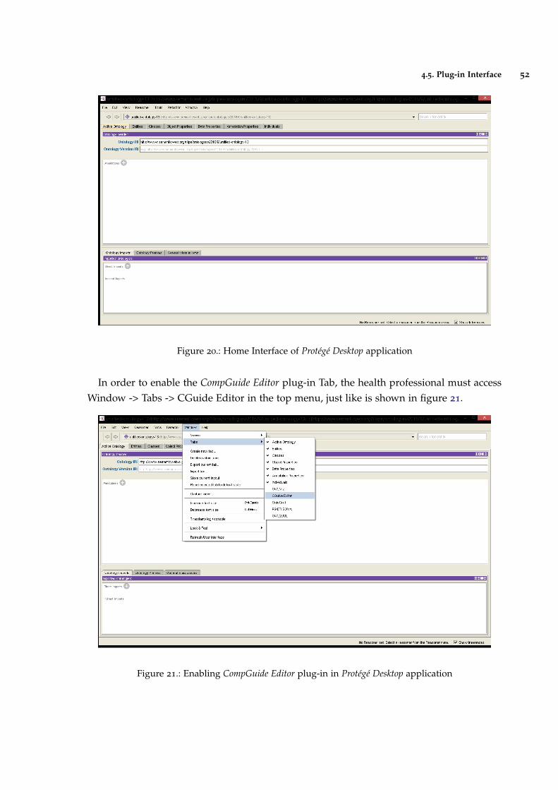
4.5. Plug-in Interface 52
Figure 20.: Home Interface of Protégé Desktop application
In order to enable the CompGuide Editor plug-in Tab, the health professional must accessWindow -> Tabs -> CGuide Editor in the top menu, just like is shown in figure 21.
Figure 21.: Enabling CompGuide Editor plug-in in Protégé Desktop application
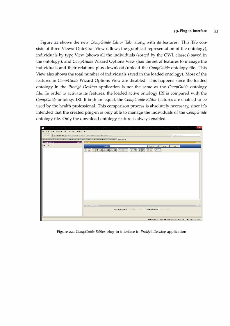
4.5. Plug-in Interface 53
Figure 22 shows the new CompGuide Editor Tab, along with its features. This Tab con-sists of three Views: OntoGraf View (allows the graphical representation of the ontology),individuals by type View (shows all the individuals (sorted by the OWL classes) saved inthe ontology.), and CompGuide Wizard Options View (has the set of features to manage theindividuals and their relations plus download/upload the CompGuide ontology file. ThisView also shows the total number of individuals saved in the loaded ontology). Most of thefeatures in CompGuide Wizard Options View are disabled. This happens since the loadedontology in the Protégé Desktop application is not the same as the CompGuide ontologyfile. In order to activate its features, the loaded active ontology IRI is compared with theCompGuide ontology IRI. If both are equal, the CompGuide Editor features are enabled to beused by the health professional. This comparison process is absolutely necessary, since it’sintended that the created plug-in is only able to manage the individuals of the CompGuideontology file. Only the download ontology feature is always enabled.
Figure 22.: CompGuide Editor plug-in interface in Protégé Desktop application
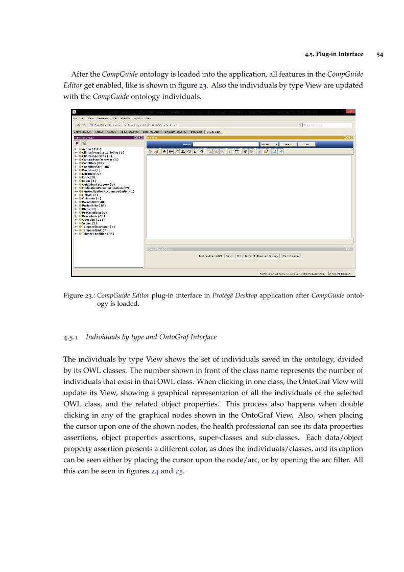
4.5. Plug-in Interface 54
After the CompGuide ontology is loaded into the application, all features in the CompGuideEditor get enabled, like is shown in figure 23. Also the individuals by type View are updatedwith the CompGuide ontology individuals.
Figure 23.: CompGuide Editor plug-in interface in Protégé Desktop application after CompGuide ontol-ogy is loaded.
4.5.1 Individuals by type and OntoGraf Interface
The individuals by type View shows the set of individuals saved in the ontology, dividedby its OWL classes. The number shown in front of the class name represents the number ofindividuals that exist in that OWL class. When clicking in one class, the OntoGraf View willupdate its View, showing a graphical representation of all the individuals of the selectedOWL class, and the related object properties. This process also happens when doubleclicking in any of the graphical nodes shown in the OntoGraf View. Also, when placingthe cursor upon one of the shown nodes, the health professional can see its data propertiesassertions, object properties assertions, super-classes and sub-classes. Each data/objectproperty assertion presents a different color, as does the individuals/classes, and its captioncan be seen either by placing the cursor upon the node/arc, or by opening the arc filter. Allthis can be seen in figures 24 and 25.
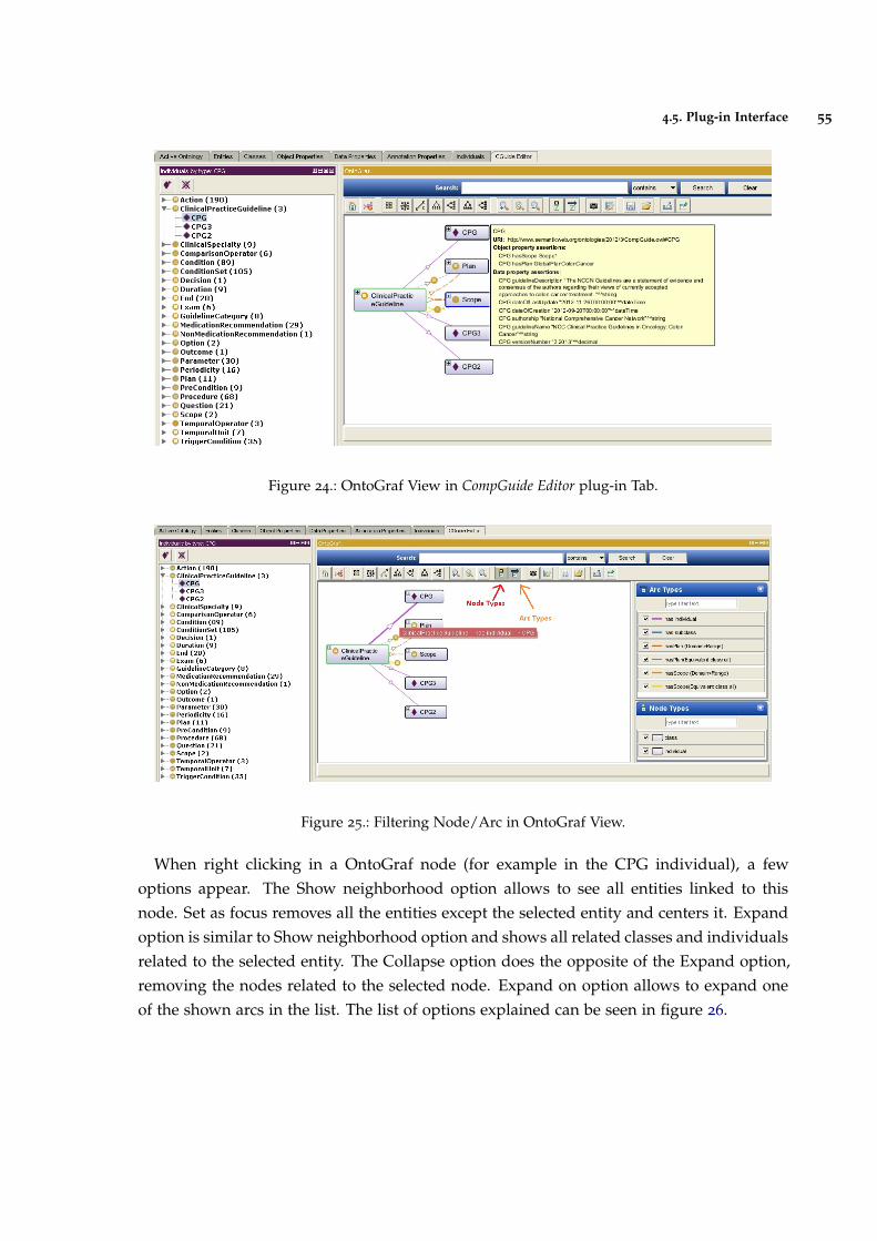
4.5. Plug-in Interface 55
Figure 24.: OntoGraf View in CompGuide Editor plug-in Tab.
Figure 25.: Filtering Node/Arc in OntoGraf View.
When right clicking in a OntoGraf node (for example in the CPG individual), a fewoptions appear. The Show neighborhood option allows to see all entities linked to thisnode. Set as focus removes all the entities except the selected entity and centers it. Expandoption is similar to Show neighborhood option and shows all related classes and individualsrelated to the selected entity. The Collapse option does the opposite of the Expand option,removing the nodes related to the selected node. Expand on option allows to expand oneof the shown arcs in the list. The list of options explained can be seen in figure 26.
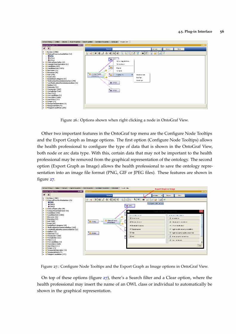
4.5. Plug-in Interface 56
Figure 26.: Options shown when right clicking a node in OntoGraf View.
Other two important features in the OntoGraf top menu are the Configure Node Tooltipsand the Export Graph as Image options. The first option (Configure Node Tooltips) allowsthe health professional to configure the type of data that is shown in the OntoGraf View,both node or arc data type. With this, certain data that may not be important to the healthprofessional may be removed from the graphical representation of the ontology. The secondoption (Export Graph as Image) allows the health professional to save the ontology repre-sentation into an image file format (PNG, GIF or JPEG files). These features are shown infigure 27.
Figure 27.: Configure Node Tooltips and the Export Graph as Image options in OntoGraf View.
On top of these options (figure 27), there’s a Search filter and a Clear option, where thehealth professional may insert the name of an OWL class or individual to automatically beshown in the graphical representation.
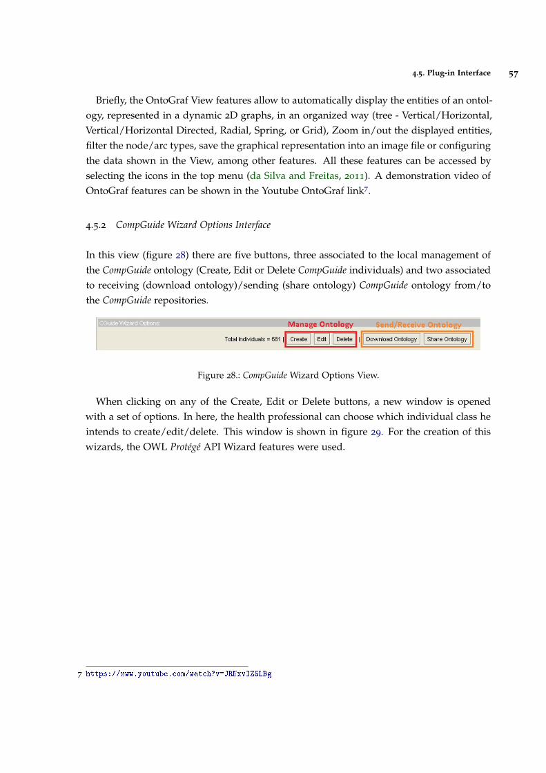
4.5. Plug-in Interface 57
Briefly, the OntoGraf View features allow to automatically display the entities of an ontol-ogy, represented in a dynamic 2D graphs, in an organized way (tree - Vertical/Horizontal,Vertical/Horizontal Directed, Radial, Spring, or Grid), Zoom in/out the displayed entities,filter the node/arc types, save the graphical representation into an image file or configuringthe data shown in the View, among other features. All these features can be accessed byselecting the icons in the top menu (da Silva and Freitas, 2011). A demonstration video ofOntoGraf features can be shown in the Youtube OntoGraf link7.
4.5.2 CompGuide Wizard Options Interface
In this view (figure 28) there are five buttons, three associated to the local management ofthe CompGuide ontology (Create, Edit or Delete CompGuide individuals) and two associatedto receiving (download ontology)/sending (share ontology) CompGuide ontology from/tothe CompGuide repositories.
Figure 28.: CompGuide Wizard Options View.
When clicking on any of the Create, Edit or Delete buttons, a new window is openedwith a set of options. In here, the health professional can choose which individual class heintends to create/edit/delete. This window is shown in figure 29. For the creation of thiswizards, the OWL Protégé API Wizard features were used.
7 https://www.youtube.com/watch?v=JRNxvIZ5LBg
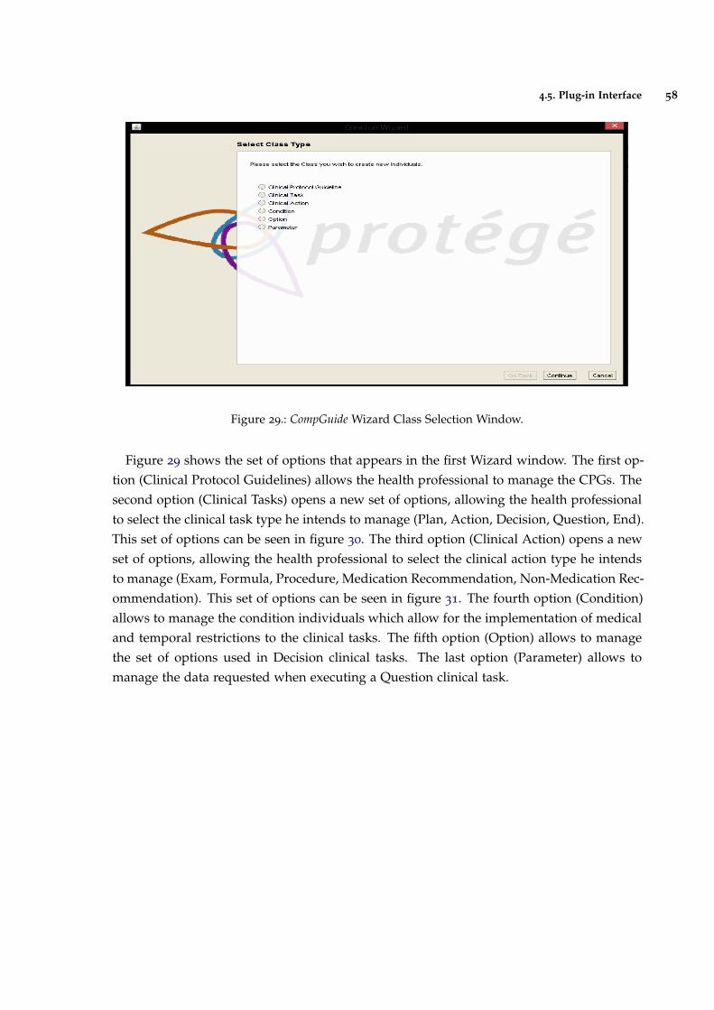
4.5. Plug-in Interface 58
Figure 29.: CompGuide Wizard Class Selection Window.
Figure 29 shows the set of options that appears in the first Wizard window. The first op-tion (Clinical Protocol Guidelines) allows the health professional to manage the CPGs. Thesecond option (Clinical Tasks) opens a new set of options, allowing the health professionalto select the clinical task type he intends to manage (Plan, Action, Decision, Question, End).This set of options can be seen in figure 30. The third option (Clinical Action) opens a newset of options, allowing the health professional to select the clinical action type he intendsto manage (Exam, Formula, Procedure, Medication Recommendation, Non-Medication Rec-ommendation). This set of options can be seen in figure 31. The fourth option (Condition)allows to manage the condition individuals which allow for the implementation of medicaland temporal restrictions to the clinical tasks. The fifth option (Option) allows to managethe set of options used in Decision clinical tasks. The last option (Parameter) allows tomanage the data requested when executing a Question clinical task.
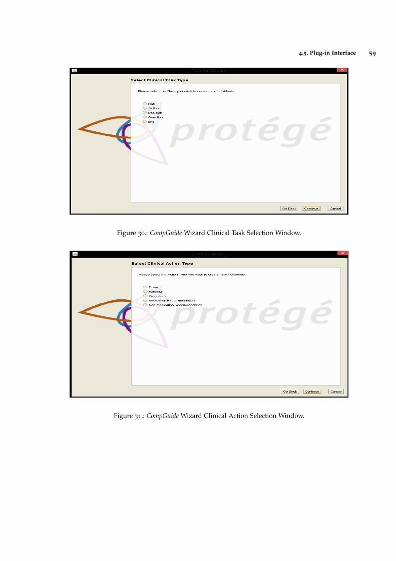
4.5. Plug-in Interface 59
Figure 30.: CompGuide Wizard Clinical Task Selection Window.
Figure 31.: CompGuide Wizard Clinical Action Selection Window.
4.5. Plug-in Interface 60
Now the interfaces creating/editing CompGuide individuals will be explained. Both thisprocesses are similar. There are only two differences between these two Wizards: whenediting, besides selecting the individual class, the health professional must also select therespective individual to edit. Although both wizards present the same interfaces, the sys-tem gets all related data to the selected individual and fills them in the Edit Wizard. Whenselecting the first option (Clinical Protocol Guidelines), a step-by-step process begins, ask-ing the health professional data related to the creation/edition of CPG. Figures 54, 55 and 56
in Annex C shows the most important windows in this step-by-step creation/edition pro-cess. Each window has a small description (top side) asking the health professional thetype of data required. Also, there was a caution to create a low complexity and automaticprocess (low number of steps where the health professional has the need to write any in-formation, having only to select the desired features into the selected individual). Thefollowing figures ask for the following data:
• Figure 54 requests the set of clinical specialties of the CPG. The health professionalmust select from the list of available specialties;
• Figure 55 requests the set of the patient conditions that should be applied in this CPG;
• Figure 56 requests the selection of the Plan associated to this CPG. As explainedbefore, it is in the Plan individual that is implemented the set of clinical tasks of theCP;
When selecting any Condition or Plan (shown in figures 55 and 56), a small descriptionof the selected individual is shown next to the list. After all data is correctly inserted, amessage informs of the creation/edition process of the CPG.
As for the clinical tasks, the Wizard allows the health professional to create/edit individ-uals of these OWL classes. The End option is an additional clinical task, used to indicatethe ending of a set of clinical tasks. As such, the individuals of this OWL class have a set ofTrigger Conditions that determine the conditions necessary to end the CP. Since the clinicaltasks have some similar (but not all) data structures, the creation/edition interfaces of theseindividuals are mostly the same. Therefore, a general explanation of the most importantwindows will be made for the management of these individuals:
• Figure 57 requests a small description of the clinical task;
• Figures 58 and 59 requests the Periodicity values and associated stop conditions re-strictions. Periodicity allows to determine the repetitive/cycle time required to applya clinical process in a particular clinical task. Conditions can be applied into thisrestriction in order to interrupt this process;
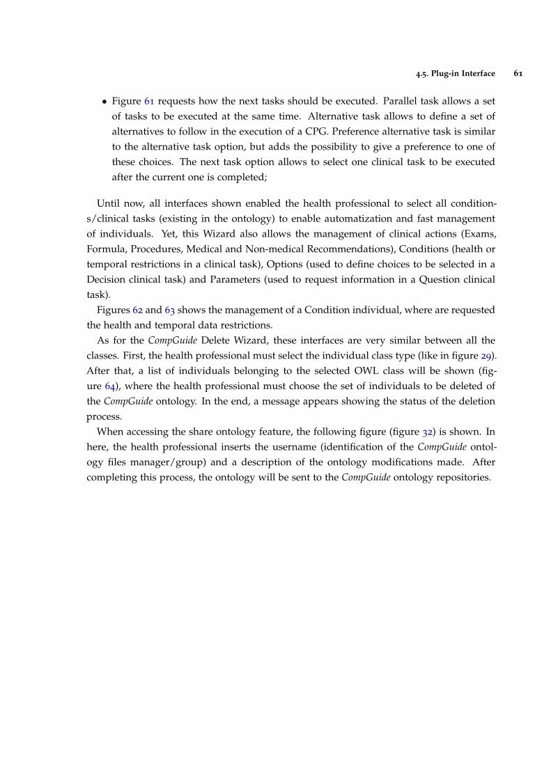
4.5. Plug-in Interface 61
• Figure 61 requests how the next tasks should be executed. Parallel task allows a setof tasks to be executed at the same time. Alternative task allows to define a set ofalternatives to follow in the execution of a CPG. Preference alternative task is similarto the alternative task option, but adds the possibility to give a preference to one ofthese choices. The next task option allows to select one clinical task to be executedafter the current one is completed;
Until now, all interfaces shown enabled the health professional to select all condition-s/clinical tasks (existing in the ontology) to enable automatization and fast managementof individuals. Yet, this Wizard also allows the management of clinical actions (Exams,Formula, Procedures, Medical and Non-medical Recommendations), Conditions (health ortemporal restrictions in a clinical task), Options (used to define choices to be selected in aDecision clinical task) and Parameters (used to request information in a Question clinicaltask).
Figures 62 and 63 shows the management of a Condition individual, where are requestedthe health and temporal data restrictions.
As for the CompGuide Delete Wizard, these interfaces are very similar between all theclasses. First, the health professional must select the individual class type (like in figure 29).After that, a list of individuals belonging to the selected OWL class will be shown (fig-ure 64), where the health professional must choose the set of individuals to be deleted ofthe CompGuide ontology. In the end, a message appears showing the status of the deletionprocess.
When accessing the share ontology feature, the following figure (figure 32) is shown. Inhere, the health professional inserts the username (identification of the CompGuide ontol-ogy files manager/group) and a description of the ontology modifications made. Aftercompleting this process, the ontology will be sent to the CompGuide ontology repositories.
4.5. Plug-in Interface 62
Figure 32.: CompGuide Share ontology Window.
4.5.3 CompGuide Git ontology Repository
When a health professional clicks the download ontology button (in the CompGuide Edi-tor plug-in), the system will download the latest updated files (compacted in a zip file)located in the CompGuide master branch Git repository. In this sub-chapter, some figureswill be shown illustrating how the admin may update these files, without interfering in theCompGuide Editor plug-in code. Figure 33 presents the CompGuide master branch Git repos-itory when accessed through GitHub website (while Git is a command line tool, GitHubprovides a Web-based graphical interface (Dabbish et al., 2012)).
8 https://github.com/filipebravo123/CompGuide_Plugin
4.5. Plug-in Interface 63
Figure 33.: CompGuide Git Master Branch Repository (exported from GitHub Website8).
To have access to this web page, the admin must first insert the login credentials and afterthe validation is complete, all GitHub features will be available. In order to update/uploadfiles to the master branch, the admin must click in the upload files button, opening the webpage presented in figure 34. After that, the admin can drag/choose the files to be upload-ed/updated into the repository and write a small description of the changes implementedin the newest version. CompGuide Git ontology repository can also be updated through theuse of Git command line.
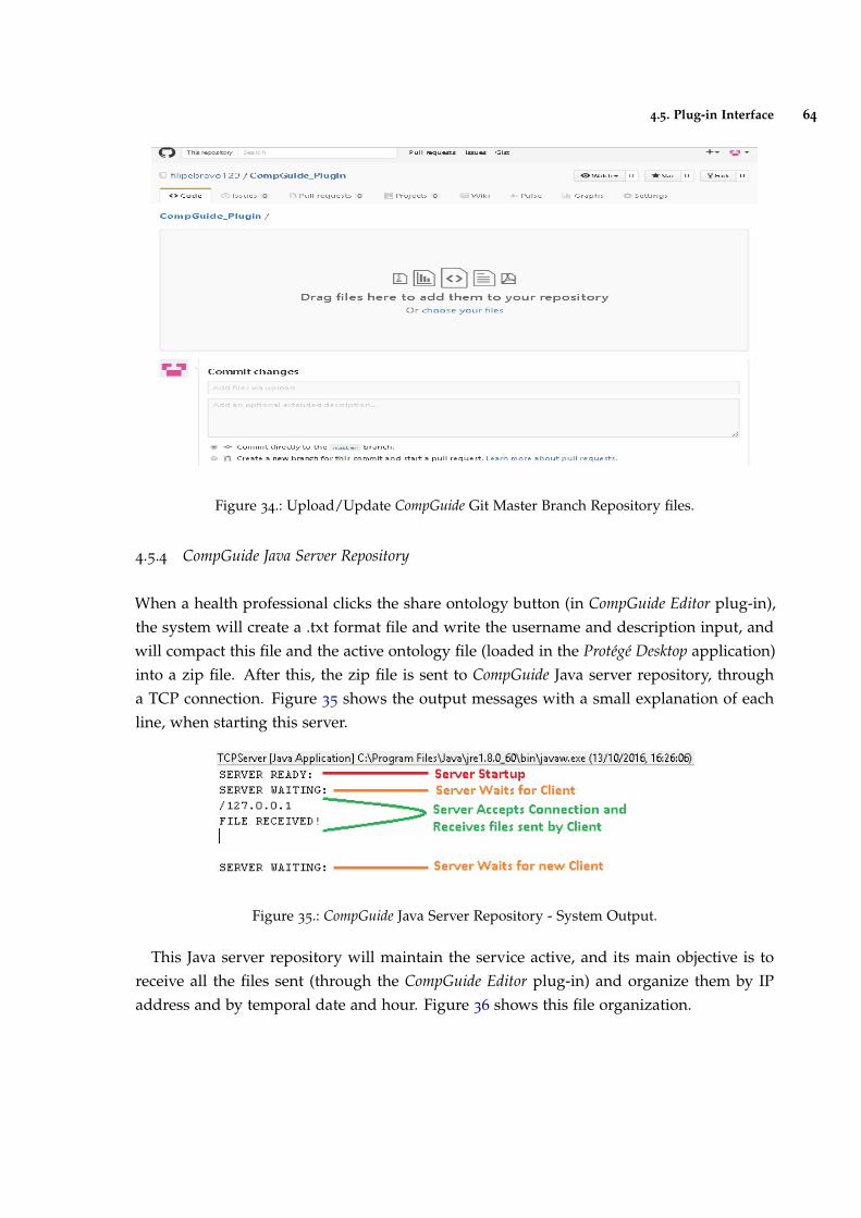
4.5. Plug-in Interface 64
Figure 34.: Upload/Update CompGuide Git Master Branch Repository files.
4.5.4 CompGuide Java Server Repository
When a health professional clicks the share ontology button (in CompGuide Editor plug-in),the system will create a .txt format file and write the username and description input, andwill compact this file and the active ontology file (loaded in the Protégé Desktop application)into a zip file. After this, the zip file is sent to CompGuide Java server repository, througha TCP connection. Figure 35 shows the output messages with a small explanation of eachline, when starting this server.
Figure 35.: CompGuide Java Server Repository - System Output.
This Java server repository will maintain the service active, and its main objective is toreceive all the files sent (through the CompGuide Editor plug-in) and organize them by IPaddress and by temporal date and hour. Figure 36 shows this file organization.
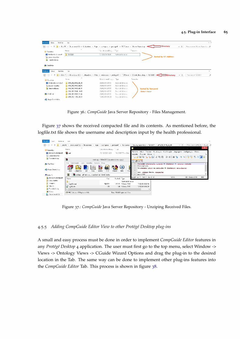
4.5. Plug-in Interface 65
Figure 36.: CompGuide Java Server Repository - Files Management.
Figure 37 shows the received compacted file and its contents. As mentioned before, thelogfile.txt file shows the username and description input by the health professional.
Figure 37.: CompGuide Java Server Repository - Unziping Received Files.
4.5.5 Adding CompGuide Editor View to other Protégé Desktop plug-ins
A small and easy process must be done in order to implement CompGuide Editor features inany Protégé Desktop 4 application. The user must first go to the top menu, select Window ->Views -> Ontology Views -> CGuide Wizard Options and drag the plug-in to the desiredlocation in the Tab. The same way can be done to implement other plug-ins features intothe CompGuide Editor Tab. This process is shown in figure 38.
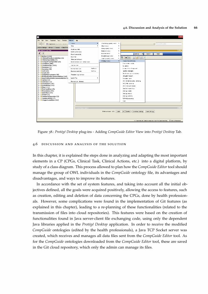
4.6. Discussion and Analysis of the Solution 66
Figure 38.: Protégé Desktop plug-ins - Adding CompGuide Editor View into Protégé Desktop Tab.
4.6 discussion and analysis of the solution
In this chapter, it is explained the steps done in analyzing and adapting the most importantelements in a CP (CPGs, Clinical Task, Clinical Actions, etc.) into a digital platform, bystudy of a class diagram. This process allowed to plan how the CompGuide Editor tool shouldmanage the group of OWL individuals in the CompGuide ontology file, its advantages anddisadvantages, and ways to improve its features.
In accordance with the set of system features, and taking into account all the initial ob-jectives defined, all the goals were acquired positively, allowing the access to features, suchas creation, editing and deletion of data concerning the CPGs, done by health profession-als. However, some complications were found in the implementation of Git features (asexplained in this chapter), leading to a re-planning of these functionalities (related to thetransmission of files into cloud repositories). This features were based on the creation offunctionalities found in Java server-client file exchanging code, using only the dependentJava libraries applied in the Protégé Desktop application. In order to receive the modifiedCompGuide ontologies (edited by the health professionals), a Java TCP Socket server wascreated, which receives and manages all data files sent from the CompGuide Editor tool. Asfor the CompGuide ontologies downloaded from the CompGuide Editor tool, these are savedin the Git cloud repository, which only the admin can manage its files.

4.6. Discussion and Analysis of the Solution 67
In this system, the admin can access and change the files stored in both the repositories.All transmitted files are compressed, reducing the required amount of data to send. In ad-dition, newer versions of CompGuide ontology can be updated in the Git repository withoutthe need to change the features of CompGuide Editor tool.
With this step finished, all objectives were acquired with positive results.

5
C O N C L U S I O N
In this chapter we will briefly describe the conclusions obtained in this work, report the setof objectives completed, limitations of the proposed solution, and introduce perspectivesfor future work.
This work focuses on the necessity of platforms for the creation and edition of CIGs,in facilitating their use by people who do not possess programming skills. CIGs holdlarge amounts of clinical knowledge which are used in CDSSs. As such it is one of thekey components in promoting improvements in the quality of clinical processes, reducingvariations in clinical practice and reducing health care costs.
Another important aspect is the support that these systems can give to health profes-sionals, which are subject to stressful situations, responsible for medical errors, variationsin clinical practice, and practice of defensive medicine. This shows that it is necessary toapproach health professionals with good clinical practice and evidence-based medicine, bygiving some assistance in the decision making with the help of computer science.
In computer science, several languages and tools exist for helping final users and systemdevelopers in creating good and effective CIGs, such as Protégé Desktop, SAGE Workbench,Tallis, GEM Cutter, Asbru View and many others. Yet most of these platforms lack someimportant features, leaving place for improvements.
By studying these tools, the creation of a plug-in for the Protégé Desktop application wasplanned, with the capacity to manage and share the CompGuide ontologies, through theuse of cloud repositories. The study and analysis of the structure of existing classes in theCompGuide ontology, as well as reading various tutorials (regarding the plug-in creationprocess) were essential in the progress of this project. The use of UML diagrams helped tokeep the focus on the set of objectives to be accomplished.
5.1 accomplishment of the objectives and contributions
Regarding the objectives defined in sub-chapter 1.9, it can be considered that they havebeen satisfactorily achieved. Taking into consideration that it was prepared an extensiveanalysis of the problem. The implementation of a tool with this level of complexity became
68
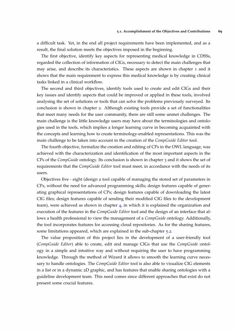
5.1. Accomplishment of the Objectives and Contributions 69
a difficult task. Yet, in the end all project requirements have been implemented, and as aresult, the final solution meets the objectives imposed in the beginning.
The first objective, identify key aspects for representing medical knowledge in CDSSs,regarded the collection of information of CIGs, necessary to detect the main challenges thatmay arise, and describe its characteristics. These aspects are shown in chapter 1 and itshows that the main requirement to express this medical knowledge is by creating clinicaltasks linked in a clinical workflow.
The second and third objectives, identify tools used to create and edit CIGs and theirkey issues and identify aspects that could be improved or applied in these tools, involvedanalysing the set of solutions or tools that can solve the problems previously surveyed. Itsconclusion is shown in chapter 2. Although existing tools provide a set of functionalitiesthat meet many needs for the user community, there are still some unmet challenges. Themain challenge is the little knowledge users may have about the terminologies and ontolo-gies used in the tools, which implies a longer learning curve in becoming acquainted withthe concepts and learning how to create terminology-enabled representations. This was themain challenge to be taken into account in the creation of the CompGuide Editor tool.
The fourth objective, formalize the creation and editing of CPs in the OWL language, wasachieved with the characterization and identification of the most important aspects in theCPs of the CompGuide ontology. Its conclusion is shown in chapter 3 and it shows the set ofrequirements that the CompGuide Editor tool must meet, in accordance with the needs of itsusers.
Objectives five - eight (design a tool capable of managing the stored set of parameters inCPs, without the need for advanced programming skills; design features capable of gener-ating graphical representations of CPs; design features capable of downloading the latestCIG files; design features capable of sending their modified CIG files to the developmentteam), were achieved as shown in chapter 4, in which it is explained the organization andexecution of the features in the CompGuide Editor tool and the design of an interface that al-lows a health professional to view the management of a CompGuide ontology. Additionally,the tool incorporates features for accessing cloud repositories. As for the sharing features,some limitations appeared, which are explained in the sub-chapter 5.2.
The value proposition of this project lies in the development of a user-friendly tool(CompGuide Editor) able to create, edit and manage CIGs that use the CompGuide ontol-ogy in a simple and intuitive way and without requiring the user to have programmingknowledge. Through the method of Wizard it allows to smooth the learning curve neces-sary to handle ontologies. The CompGuide Editor tool is also able to visualize CIG elementsin a list or in a dynamic 2D graphic, and has features that enable sharing ontologies with aguideline development team. This need comes since different approaches that exist do notpresent some crucial features.
5.2. Limitations and Perspectives for future work 70
5.2 limitations and perspectives for future work
A major limitation in building the CompGuide Editor plug-in took place in the creation offeatures related to the download/upload of ontological files. The initial idea was to usethe features of the free Git platform, in order to manage all file sharing within a cloudrepository, without any financial cost. However, since the CompGuide Editor tool is a plug-inthat runs dependent of Protégé Desktop application APIs, the use of external APIs becamevery difficult. The way to solve this problem was to create sharing features using only theAPIs used by the Protégé Desktop application. Despite this limitation, these features havebeen successfully created, as it is shown in chapter 4.
Although the CompGuide Editor plug-in displays sharing functionalities of the CompGuideontology, this feature only sends/receives the corresponding ontological file to a cloudrepository. To access the data presented in this file, the user must open it with an OWL filemanager. Mapping all this information to a database would be an asset in the managementof the CompGuide ontologies. With the ontology imported into a database, the user wouldsimply need to do queries from the Protégé Desktop interface, where all changes would besaved directly into the cloud repository. This is a relevant aspect for future developmentsof the tool.
SPARQL Protégé plug-in 1 provides support for composing and executing database queriesfrom within the Protégé Desktop interface, and could be one of the solutions for this futurework.
However, these features are dependent of a tool that would import the CompGuide ontol-ogy into the database, providing quick updates to the data stored in the cloud.
1 http://protegewiki.stanford.edu/wiki/SPARQL_Query
B I B L I O G R A P H Y
Adratt, Eduardo and LIMA, L and BARRA, C. (2004). Guidelines: Fundamentos Teóricos eEvolução Tecnológica dentro da Medicina. In IX Congresso Brasiliero Informática em Saúde(CBIS), pages 07–10.
Allen, J. D. and Unicode Consortium. (2007). The Unicode standard 5.0. Addison-Wesley.
Beard, N., Campbell, J. R., Huff, S. M., Leon, M., Mansfield, J. G., Mays, E., McClay, J. C.,Mohr, D. N., Musen, M. A., O’Brien, D., et al. (2002). Standards-based sharable activeguideline environment (sage): A project to develop a universal framework for encodingand disseminating electronic clinical practice guidelines. In AMIA.
Bechhofer, S., Hendler, J., Patel-Schneider, P. F., Stein, L. A., and Olin, F. W. (2004). OWLWeb Ontology Language Reference.
Benko, A. and Sik Lányi, C. (2009). Encyclopedia of Information Science and Technology, SecondEdition. IGI Global.
Berner, E. S. (2007). Clinical decision support systems. Springer.
Bittner, K. (2002). Use case modeling. Addison-Wesley Longman Publishing Co., Inc.
Boggs, W. and Boggs, M. (2002). Mastering UML with rational rose 2002. Sybex.
Bott, R. (2014). Summary of the Guideline Workbenches Evaluation. Igarss 2014, (1):1–5.
Briand, L. C., Labiche, Y., and Miao, Y. (2003). Towards the Reverse Engineering of UMLSequence Diagrams.
Chim, JCS and Cheung, NT and Fung, H and Wong, K. (2003). Electronic clinical practiceguidelines: current status and future prospects in Hong Kong. Hong Kong Medical Journal,9(4):299—-301.
Chung, L., Nixon, B. A., Yu, E., and Mylopoulos, J. (2012). Non-functional requirements insoftware engineering, volume 5. Springer Science & Business Media.
Clancey, W. J. and Shortliffe, E. H. (1984). Readings in medical artificial intelligence: thefirst decade.
Cockburn, A. (2008). Why I still use use cases. alistair.cockburn.us.
71
Bibliography 72
Cristani, Matteo and Cuel, R. (2005). A Survey on Ontology Creation Methodologies. Int. J.Semantic Web Inf. Syst., 1(2):49—-69.
da Silva, I. C. S. and Freitas, C. M. D. S. (2011). Using visualization for exploring relation-ships between concepts in ontologies. In 2011 15th International Conference on InformationVisualisation, pages 317–322. IEEE.
Dabbish, L., Stuart, C., Tsay, J., and Herbsleb, J. (2012). Social coding in github: transparencyand collaboration in an open software repository. In Proceedings of the ACM 2012 conferenceon Computer Supported Cooperative Work, pages 1277–1286. ACM.
de Clercq, P. A., Blom, J. A., Korsten, H. H. M., and Hasman, A. (2004). Approachesfor creating computer-interpretable guidelines that facilitate decision support. Artificialintelligence in medicine, 31(1):1–27.
Douglass, B. P. (2003). Real time uml. In Formal Techniques in Real-Time and Fault-TolerantSystems: 7th International Symposium, FTRTFT 2002, Co-sponsored by IFIP WG 2.2, Oldenburg,Germany, September 9-12, 2002. Proceedings, volume 2469, page 53. Springer.
Eysenbach, G. (2001). What is e-health? Journal of medical Internet research, 3(2):e20.
Eysenck, M. and Keane, M. T. (2005). Cognitive Psychology: A Student’s Handbook: A Student’sHandbook 5th Edition. Psychology Press.
Field, M. J., Lohr, K. N., et al. (1992). Guidelines for clinical practice: from development to use.National Academies Press.
Fox, J., Johns, N., Lyons, C., Rahmanzadeh, A., Thomson, R., and Wilson, P. (1997). Pro-forma: a general technology for clinical decision support systems. Computer methods andprograms in biomedicine, 54(1):59–67.
Gandrud, C. (2013). Github: A tool for social data set development and verification in thecloud. Available at SSRN 2199367.
Gomaa, H. (2001). Designing concurrent, distributed, and real-time applications with uml.In Proceedings of the 23rd international conference on software engineering, pages 737–738.IEEE Computer Society.
Gopher, D., Olin, M., Badihi, Y., Cohen, G., Donchin, Y., Bieski, M., and Cotev, S. (1989).The Nature and Causes of Human Errors in a Medical Intensive Care Unit. Proceedings ofthe Human Factors and Ergonomics Society Annual Meeting, 33(15):956–960.
Gosling, J. and Mcgilton, H. (1996). The JavaTM Language Environment.
Bibliography 73
Grilli, R. and Lomas, J. (1994). Evaluating the message: the relationship between compliancerate and the subject of a practice guideline. Medical care, 32(3):202–13.
Heflin, J., Hendler, J., and Luke, S. (1999). SHOE: A Knowledge Representation Languagefor Internet Applications.
Horn, W. (2001). AI in medicine on its way from knowledge-intensive to data-intensivesystems. Artificial Intelligence in Medicine, 23(1):5–12.
Horridge, M. and Bechhofer, S. (2009). The owl api: a java api for working with owl2 ontologies. In Proceedings of the 6th International Conference on OWL: Experiences andDirections-Volume 529, pages 49–58. CEUR-WS. org.
Horrocks, I., Patel-Schneider, P. F., and van Harmelen, F. (2003). From SHIQ and RDF toOWL: the making of a Web Ontology Language. Web Semantics: Science, Services andAgents on the World Wide Web, 1(1):7–26.
Hripcsak, G. (1994). Writing arden syntax medical logic modules. Computers in biology andmedicine, 24(5):331–363.
Huber, B. (2005). Asbruview 2.0 User Guide.
Isern, D. and Moreno, A. (2008). Computer-based execution of clinical guidelines: a review.International journal of medical informatics, 77(12):787–808.
Jacobson, I., Bittner, K., and Spence, I. (2011). Use Case 2.0: The Guide to Succeeding with UseCases. Ivar Jacobson International.
Karras, B. T., Nath, S., and Shiffman, R. N. (2000). A preliminary evaluation of guidelinecontent mark-up using gem–an xml guideline elements model. In Proceedings of the AMIASymposium, page 413. American Medical Informatics Association.
Khalifa, M. (2014). Clinical Decision Support: Strategies for Success. Procedia ComputerScience, 37:422–427.
Kim, J and Shim, BinGu and Kim, SunTae and Lee, JaeHoon and Cho, InSook and Kim, Y.(2009). Translation Protégé knowledge for executing clinical guidelines. In Proceedings ofConference Protege.
Knublauch, H., Fergerson, R. W., Noy, N. F., and Musen, M. A. (2004). The protégé owl plu-gin: An open development environment for semantic web applications. In InternationalSemantic Web Conference, pages 229–243. Springer.
Knublauch, H., Horridge, M., Musen, M. A., Rector, A. L., Stevens, R., Drummond, N.,Lord, P. W., Noy, N. F., Seidenberg, J., and Wang, H. (2005). The protege owl experience.In OWLED.
Bibliography 74
Kononenko, I. (2001). Machine learning for medical diagnosis: history, state of the art andperspective. Artificial Intelligence in Medicine, 23(1):89–109.
Leape, L. L., Lawthers, A. G., Brennan, T. A., and Johnson, W. G. (1993). Preventing medicalinjury. QRB. Quality review bulletin, 19(5):144–9.
Lee, H., Seo, B.-K., and Seo, E. (2013). A git source repository analysis tool based on anovel branch-oriented approach. In 2013 International Conference on Information Scienceand Applications (ICISA), pages 1–4. IEEE.
Leong, T. Y., Kaiser, K., and Miksch, S. (2007). Free and open source enabling technologiesfor patient-centric, guideline-based clinical decision support: a survey. Yearbook of medicalinformatics, pages 74–86.
Liu, L. and Özsu, M. T. (2009). Encyclopedia of database systems, volume 6. Springer Berlin,Heidelberg, Germany.
Loeliger, J. (2006). Collaborating with git. Linux Magazine, June.
Loeliger, J. and McCullough, M. (2012). Version Control with Git: Powerful tools and techniquesfor collaborative software development. " O’Reilly Media, Inc.".
Lozano, E., Marcos, M., Martínez-Salvador, B., Alonso, A., and Alonso, J. R. (2009). Experi-ences in the development of electronic care plans for the management of comorbidities. InInternational Workshop on Knowledge Representation for Health Care, pages 113–123. Springer.
Martínez-Salvador, B. and Marcos, M. (2016). Supporting the refinement of clinical pro-cess models to computer-interpretable guideline models. Business & Information SystemsEngineering, 58(5):355–366.
McCarthy, J. (2001). What is Artificial Intelligence? 0(sep 28):14.
Mcguinness, D., Fikes, R., Hendler, J., and Stein, L. (2002). DAML+OIL: an ontology lan-guage for the Semantic Web. IEEE Intelligent Systems, 17(5):72–80.
McGuinness, D. L., Van Harmelen, F., et al. (2004). Owl web ontology language overview.W3C recommendation, 10(10):2004.
Michel, G. and Shiffman, R. (2009). GEM Cutter 2.5 User Guide.
Musen, M. A. and Protégé Team (2015). The Protégé Project: A Look Back and a LookForward. AI matters, 1(4):4–12.
Noy, N. F., Crubézy, M., Fergerson, R. W., Knublauch, H., Tu, S. W., Vendetti, J., Musen,M. A., et al. (2003). Protege-2000: an open-source ontology-development and knowledge-acquisition environment. In AMIA Annu Symp Proc, volume 953, page 953.
Bibliography 75
Noy, Natalya F and Sintek, Michael and Decker, Stefan and Crubézy, Monica and Fergerson,Ray W and Musen, M. A. (2001). Creating semantic web contents with protege-2000. IEEEintelligent systems, (2):60—-71.
Oettinger, A. (2005). The Tallis Composer User Interface.
Oliveira, T., Leão, P., Novais, P., and Neves, J. (2014). Webifying the Computerized Ex-ecution of Clinical Practice Guidelines. Trends in Practical Applications of HeterogeneousMulti-Agent Systems. The PAAMS Collection SE - 18, 293:149–156.
Oliveira, T., Neves, J., Barbosa, E., and Novais, P. (2013a). Clinical Careflows Aided byUncertainty Representation Models. Hybrid Artificial Intelligent Systems, 8073(i):71–80.
Oliveira, T., Novais, P., and Neves, J. (2013b). Representation of clinical practice guidelinecomponents in owl. In Trends in Practical Applications of Agents and Multiagent Systems,pages 77–85. Springer.
Oliveira, Tiago and Novais, Paulo and Neves, J. (2013). Representation of Clinical PracticeGuideline Components in OWL. In Trends in Practical Applications of Agents and MultiagentSystems, pages 77—-85. Springer.
Patel, V. L., Allen, V. G., Arocha, J. F., and Shortliffe, E. H. (1998). Representing clinicalguidelines in glif. Journal of the American Medical Informatics Association, 5(5):467–483.
Patel-Schneider, D. F., van Harmelen, F., Horrocks, I., McGuinness, D. L., and F., P. (2001).OIL: An Ontology Infrastructure for the Semantic Web. IEEE Intelligent Systems, 16(1541-1672):38–45.
Peleg, M., Tu, S., Bury, J., Ciccarese, P., Fox, J., Greenes, R. A., Hall, R., Johnson, P. D.,Jones, N., Kumar, A., et al. (2003). Comparing computer-interpretable guideline models:a case-study approach. Journal of the American Medical Informatics Association, 10(1):52–68.
Pohl, K. (2010). Requirements engineering: fundamentals, principles, and techniques. SpringerPublishing Company, Incorporated.
Polvani, K.-A., Agrawal, A., Karras, B., Deshpande, A., and Shiffman, R. (2000). Gem cuttermanual. Yale Center for Medical Informatics, pages 122–131.
Purchase, H. C., Colpoys, L., Mcgill, M., Carrington, D., and Britton, C. UML class diagramsyntax: an empirical study of comprehension.
Purchase, H. C., Colpoys, L., McGill, M., Carrington, D., and Britton, C. (2001). Uml class di-agram syntax: an empirical study of comprehension. In Proceedings of the 2001 Asia-Pacificsymposium on Information visualisation-Volume 9, pages 113–120. Australian Computer So-ciety, Inc.
Bibliography 76
Rospocher, M., Eccher, C., Ghidini, C., Hasan, R., Seyfang, A., Ferro, A., and Miksch, S.(2010). Collaborative encoding of asbru clinical protocols. In International Conference onElectronic Healthcare, pages 135–143. Springer.
Rubin, D. L., Noy, N. F., and Musen, M. A. (2007). Protege: a tool for managing and usingterminology in radiology applications. Journal of Digital Imaging, 20(1):34–46.
Saridis, G. N. (2001). Hierarchically Intelligent Machines. World Scientific.
Shiffman, R. N., Agrawal, A., Deshpande, A. M., and Gershkovich, P. (2001). An approachto guideline implementation with gem. Studies in health technology and informatics, (1):271–275.
Somekh and Bridget (2005). Action Research: A Methodology For Change And Development: AMethodology for Change and Development.
Steele, R. and Primer, F. J. T. P. (2002). Introduction to proforma language and softwarewith worked examples. Technical report, Technical report. London, UK: Advanced Com-putation Laboratory, Cancer Research.
Steele, Rory and Primer, F. J. T. P. (2002). Introduction to PROforma language and soft-ware with worked examples. Technical report, Technical report. London, UK: AdvancedComputation Laboratory, Cancer Research.
Sutton, D. R. and Fox, J. (2003). The syntax and semantics of the proforma guidelinemodeling language. Journal of the American Medical Informatics Association, 10(5):433–443.
ten Teije, A., Miksch, S., and Lucas, P. (2008). Computer-based Medical Guidelines and Protocols:A Primer and Current Trends. IOS Press.
Timnat, S., Braginsky, A., Kogan, A., and Petrank, E. (2012). Wait-Free Linked-Lists.
und Naturwissenschaften, S. G. V. f. M. (2015). Archive. IMIA Yearbook, pages 145–158.
Van Lamsweerde, A. (2009). Requirements engineering: from system goals to UML models tosoftware specifications. Wiley Publishing.
Votruba, P. (2003). Structured knowledge acquisition for asbru. na.
Wang, X. H., Zhang, D. Q., Gu, T., and Pung, H. K. (2004). Ontology based context modelingand reasoning using owl. In Pervasive Computing and Communications Workshops, 2004.Proceedings of the Second IEEE Annual Conference on, pages 18–22. Ieee.
Wei, Z. and Hong, M. (2003). A feature-oriented domain model and its modeling process.Journal of Software, 14(8):1345–1356.

Bibliography 77
Wiegers, K. E. (2003). Software requirements : practical techniques for gathering and manag-ing requirements throughout the product development cycle. Microsoft Press, Redmond, 2ndedition.
Young, R. R. (2001). Effective requirements practices. Addison-Wesley.

AU S E C A S E T E X T D E S C R I P T I O N S
This Annex provides a description of the different use cases running in the CompGuideEditor system, in the form of tables 2-9. These use case descriptions are properly explainedin sub-chapter 4.4. Create Wizard Use Case Text Description is related with the creationfeatures, Edit Wizard Use Case Text Description is related with the edition features andDelete Wizard Use Case Text Description is related with the delete features, which are allmanaged locally. The rest of the use case descriptions are associated with the downloadand share of ontology features (from both client and server side), which are dependent ofthe internet connectivity, as it is shown in the pre-condition.
States Caption:
• UD - User Defined (feature accessed by the user);
• OUT - Output (data output by the system);
• INP - Input (data input by the user);
• VAL - Validation (system validation of a condition);
• IVAL - Input Validation (system validation of the input data by the user);
• ALT - Alternative (shows an alternative from the current process);
78
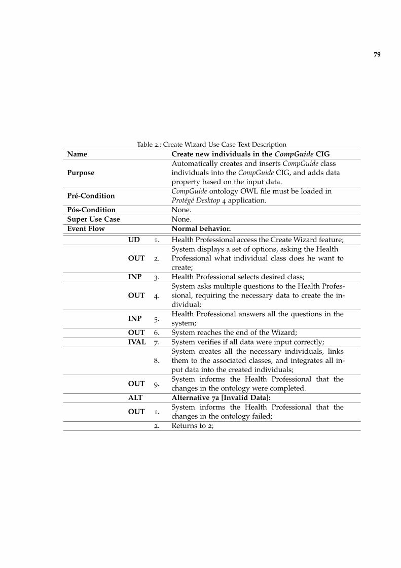
79
Table 2.: Create Wizard Use Case Text DescriptionName Create new individuals in the CompGuide CIG
PurposeAutomatically creates and inserts CompGuide classindividuals into the CompGuide CIG, and adds dataproperty based on the input data.
Pré-ConditionCompGuide ontology OWL file must be loaded inProtégé Desktop 4 application.
Pós-Condition None.Super Use Case None.Event Flow Normal behavior.
UD 1. Health Professional access the Create Wizard feature;
OUT 2.System displays a set of options, asking the HealthProfessional what individual class does he want tocreate;
INP 3. Health Professional selects desired class;
OUT 4.System asks multiple questions to the Health Profes-sional, requiring the necessary data to create the in-dividual;
INP 5.Health Professional answers all the questions in thesystem;
OUT 6. System reaches the end of the Wizard;IVAL 7. System verifies if all data were input correctly;
8.System creates all the necessary individuals, linksthem to the associated classes, and integrates all in-put data into the created individuals;
OUT 9.System informs the Health Professional that thechanges in the ontology were completed.
ALT Alternative 7a [Invalid Data]:
OUT 1.System informs the Health Professional that thechanges in the ontology failed;
2. Returns to 2;
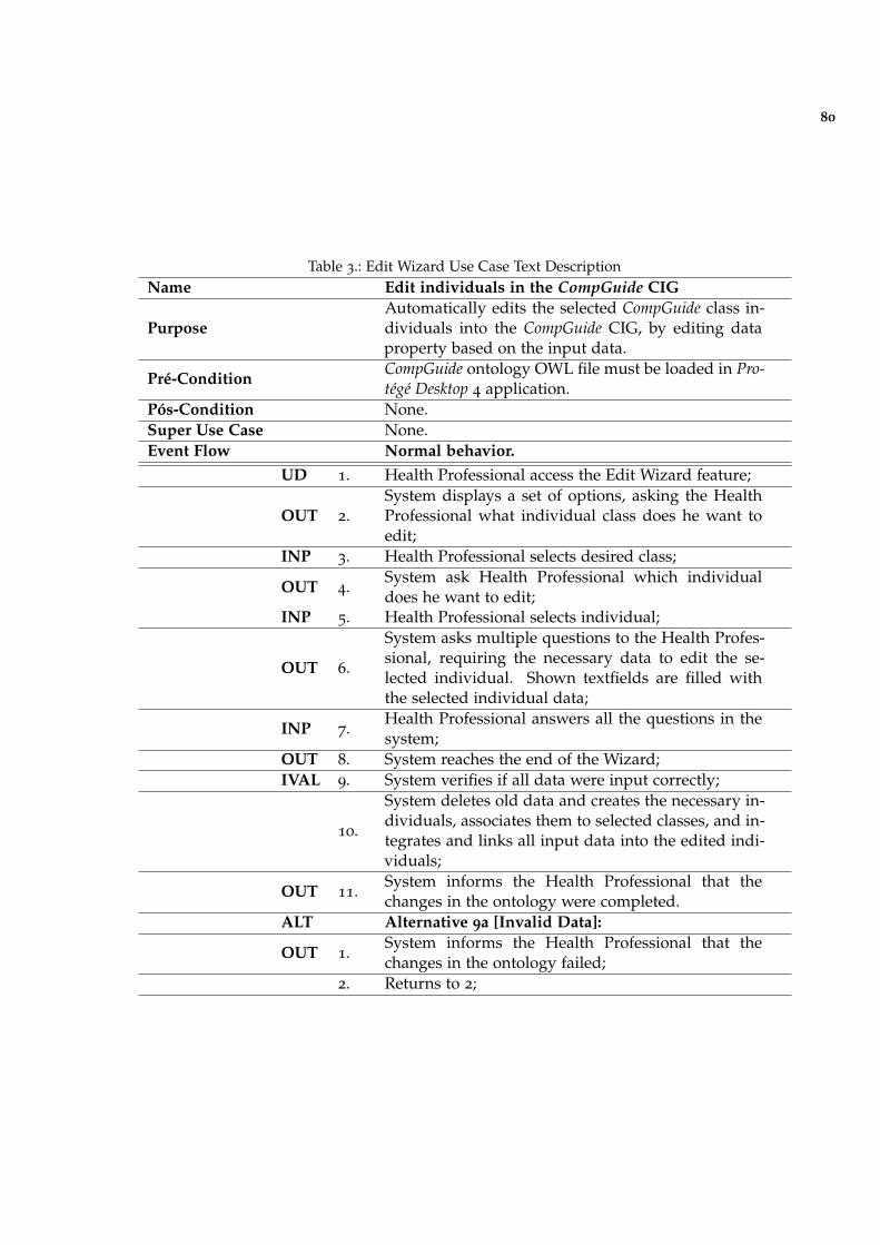
80
Table 3.: Edit Wizard Use Case Text DescriptionName Edit individuals in the CompGuide CIG
PurposeAutomatically edits the selected CompGuide class in-dividuals into the CompGuide CIG, by editing dataproperty based on the input data.
Pré-ConditionCompGuide ontology OWL file must be loaded in Pro-tégé Desktop 4 application.
Pós-Condition None.Super Use Case None.Event Flow Normal behavior.
UD 1. Health Professional access the Edit Wizard feature;
OUT 2.System displays a set of options, asking the HealthProfessional what individual class does he want toedit;
INP 3. Health Professional selects desired class;
OUT 4.System ask Health Professional which individualdoes he want to edit;
INP 5. Health Professional selects individual;
OUT 6.
System asks multiple questions to the Health Profes-sional, requiring the necessary data to edit the se-lected individual. Shown textfields are filled withthe selected individual data;
INP 7.Health Professional answers all the questions in thesystem;
OUT 8. System reaches the end of the Wizard;IVAL 9. System verifies if all data were input correctly;
10.
System deletes old data and creates the necessary in-dividuals, associates them to selected classes, and in-tegrates and links all input data into the edited indi-viduals;
OUT 11.System informs the Health Professional that thechanges in the ontology were completed.
ALT Alternative 9a [Invalid Data]:
OUT 1.System informs the Health Professional that thechanges in the ontology failed;
2. Returns to 2;
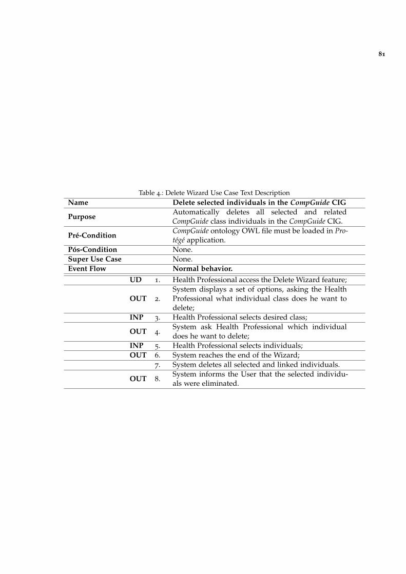
81
Table 4.: Delete Wizard Use Case Text DescriptionName Delete selected individuals in the CompGuide CIG
PurposeAutomatically deletes all selected and relatedCompGuide class individuals in the CompGuide CIG.
Pré-ConditionCompGuide ontology OWL file must be loaded in Pro-tégé application.
Pós-Condition None.Super Use Case None.Event Flow Normal behavior.
UD 1. Health Professional access the Delete Wizard feature;
OUT 2.System displays a set of options, asking the HealthProfessional what individual class does he want todelete;
INP 3. Health Professional selects desired class;
OUT 4.System ask Health Professional which individualdoes he want to delete;
INP 5. Health Professional selects individuals;OUT 6. System reaches the end of the Wizard;
7. System deletes all selected and linked individuals.
OUT 8.System informs the User that the selected individu-als were eliminated.
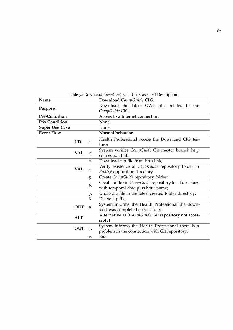
82
Table 5.: Download CompGuide CIG Use Case Text DescriptionName Download CompGuide CIG.
PurposeDownload the latest OWL files related to theCompGuide CIG.
Pré-Condition Access to a Internet connection.Pós-Condition None.Super Use Case None.Event Flow Normal behavior.
UD 1.Health Professional access the Download CIG fea-ture;
VAL 2.System verifies CompGuide Git master branch httpconnection link;
3. Download zip file from http link;
VAL 4.Verify existence of CompGuide repository folder inProtégé application directory.
5. Create CompGuide repository folder;
6.Create folder in CompGuide repository local directorywith temporal date plus hour name;
7. Unzip zip file in the latest created folder directory;8. Delete zip file;
OUT 9.System informs the Health Professional the down-load was completed successfully.
ALTAlternative 2a [CompGuide Git repository not acces-sible]
OUT 1.System informs the Health Professional there is aproblem in the connection with Git repository;
2. End
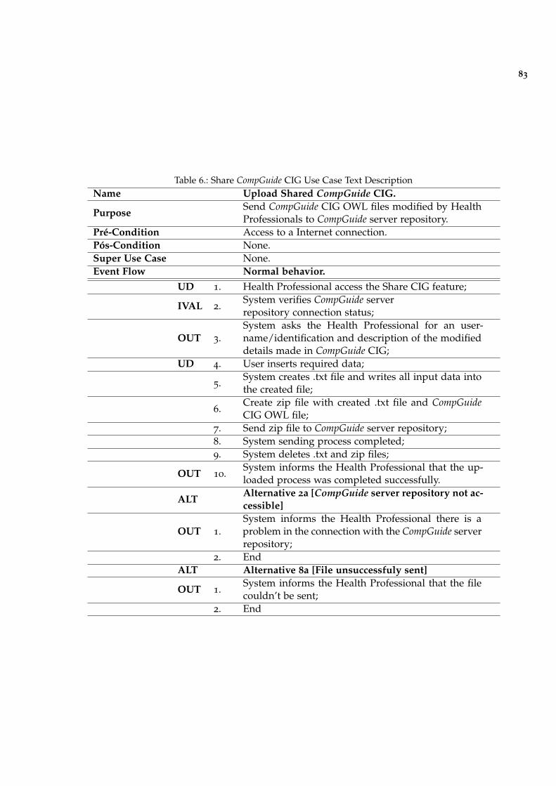
83
Table 6.: Share CompGuide CIG Use Case Text DescriptionName Upload Shared CompGuide CIG.
PurposeSend CompGuide CIG OWL files modified by HealthProfessionals to CompGuide server repository.
Pré-Condition Access to a Internet connection.Pós-Condition None.Super Use Case None.Event Flow Normal behavior.
UD 1. Health Professional access the Share CIG feature;
IVAL 2.System verifies CompGuide serverrepository connection status;
OUT 3.System asks the Health Professional for an user-name/identification and description of the modifieddetails made in CompGuide CIG;
UD 4. User inserts required data;
5.System creates .txt file and writes all input data intothe created file;
6.Create zip file with created .txt file and CompGuideCIG OWL file;
7. Send zip file to CompGuide server repository;8. System sending process completed;9. System deletes .txt and zip files;
OUT 10.System informs the Health Professional that the up-loaded process was completed successfully.
ALTAlternative 2a [CompGuide server repository not ac-cessible]
OUT 1.System informs the Health Professional there is aproblem in the connection with the CompGuide serverrepository;
2. EndALT Alternative 8a [File unsuccessfuly sent]
OUT 1.System informs the Health Professional that the filecouldn’t be sent;
2. End
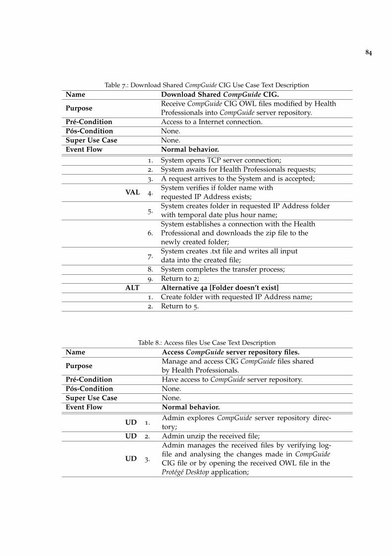
84
Table 7.: Download Shared CompGuide CIG Use Case Text DescriptionName Download Shared CompGuide CIG.
PurposeReceive CompGuide CIG OWL files modified by HealthProfessionals into CompGuide server repository.
Pré-Condition Access to a Internet connection.Pós-Condition None.Super Use Case None.Event Flow Normal behavior.
1. System opens TCP server connection;2. System awaits for Health Professionals requests;3. A request arrives to the System and is accepted;
VAL 4.System verifies if folder name withrequested IP Address exists;
5.System creates folder in requested IP Address folderwith temporal date plus hour name;
6.System establishes a connection with the HealthProfessional and downloads the zip file to thenewly created folder;
7.System creates .txt file and writes all inputdata into the created file;
8. System completes the transfer process;9. Return to 2;
ALT Alternative 4a [Folder doesn’t exist]1. Create folder with requested IP Address name;2. Return to 5.
Table 8.: Access files Use Case Text DescriptionName Access CompGuide server repository files.
PurposeManage and access CIG CompGuide files sharedby Health Professionals.
Pré-Condition Have access to CompGuide server repository.Pós-Condition None.Super Use Case None.Event Flow Normal behavior.
UD 1.Admin explores CompGuide server repository direc-tory;
UD 2. Admin unzip the received file;
UD 3.
Admin manages the received files by verifying log-file and analysing the changes made in CompGuideCIG file or by opening the received OWL file in theProtégé Desktop application;
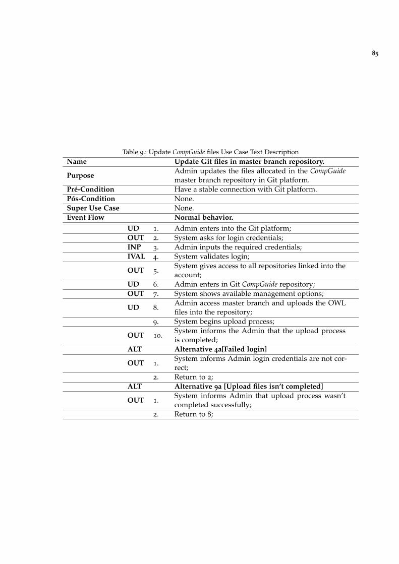
85
Table 9.: Update CompGuide files Use Case Text DescriptionName Update Git files in master branch repository.
PurposeAdmin updates the files allocated in the CompGuidemaster branch repository in Git platform.
Pré-Condition Have a stable connection with Git platform.Pós-Condition None.Super Use Case None.Event Flow Normal behavior.
UD 1. Admin enters into the Git platform;OUT 2. System asks for login credentials;INP 3. Admin inputs the required credentials;IVAL 4. System validates login;
OUT 5.System gives access to all repositories linked into theaccount;
UD 6. Admin enters in Git CompGuide repository;OUT 7. System shows available management options;
UD 8.Admin access master branch and uploads the OWLfiles into the repository;
9. System begins upload process;
OUT 10.System informs the Admin that the upload processis completed;
ALT Alternative 4a[Failed login]
OUT 1.System informs Admin login credentials are not cor-rect;
2. Return to 2;ALT Alternative 9a [Upload files isn’t completed]
OUT 1.System informs Admin that upload process wasn’tcompleted successfully;
2. Return to 8;
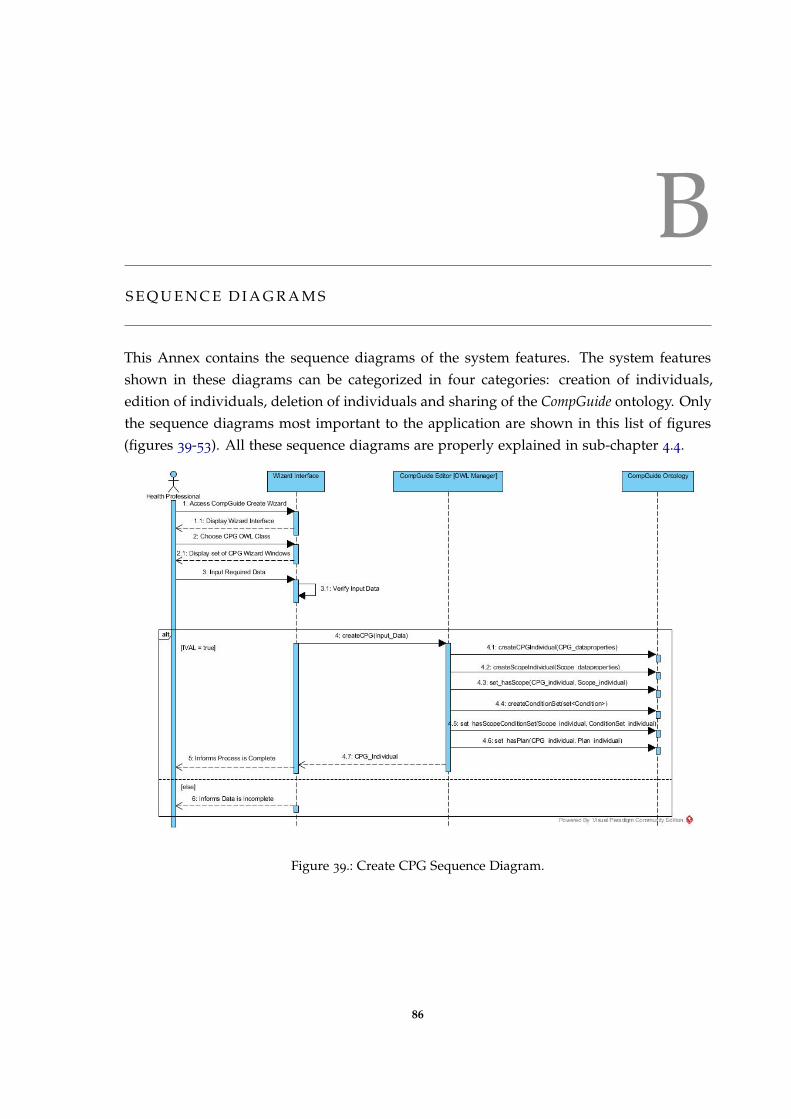
BS E Q U E N C E D I A G R A M S
This Annex contains the sequence diagrams of the system features. The system featuresshown in these diagrams can be categorized in four categories: creation of individuals,edition of individuals, deletion of individuals and sharing of the CompGuide ontology. Onlythe sequence diagrams most important to the application are shown in this list of figures(figures 39-53). All these sequence diagrams are properly explained in sub-chapter 4.4.
Figure 39.: Create CPG Sequence Diagram.
86
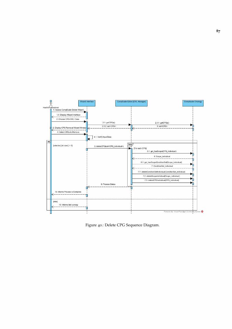
87
Figure 40.: Delete CPG Sequence Diagram.
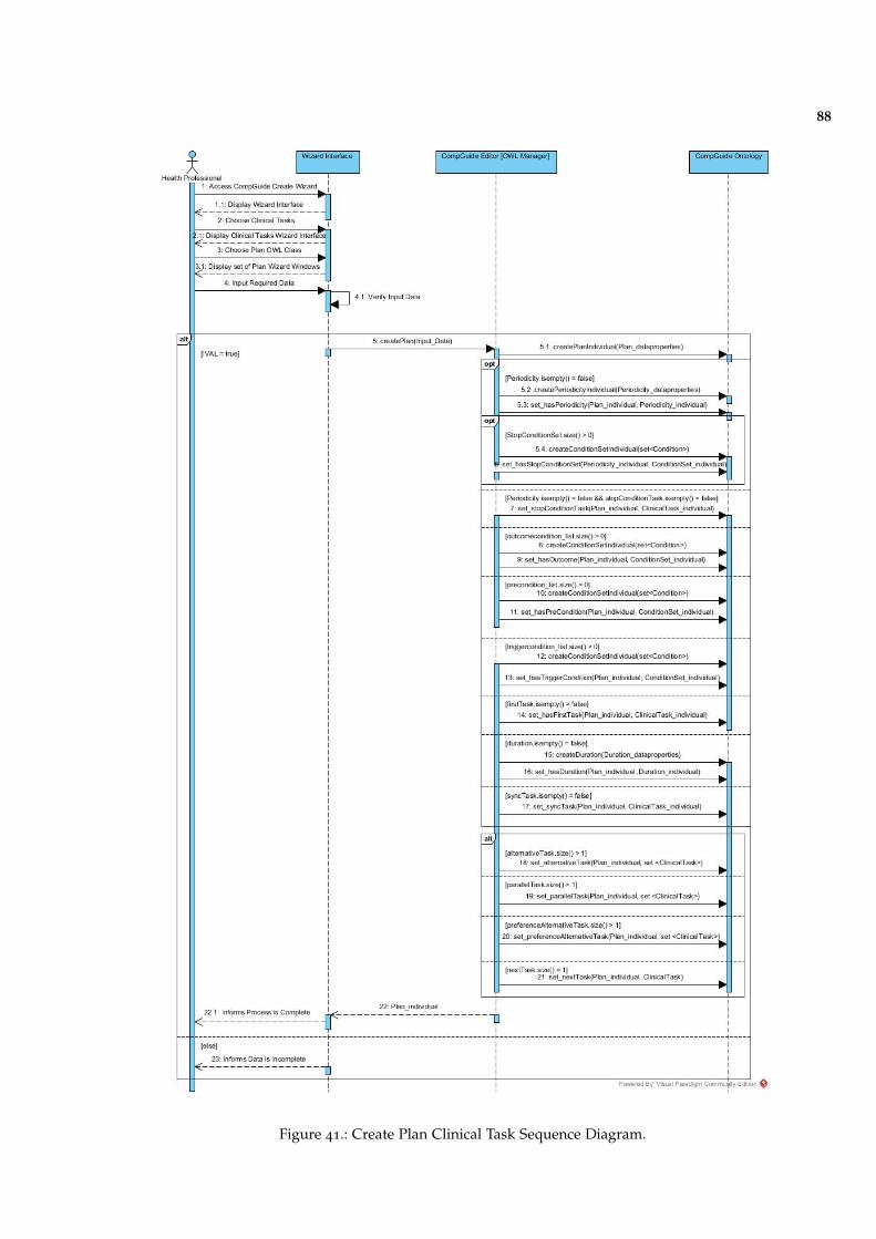
88
Figure 41.: Create Plan Clinical Task Sequence Diagram.
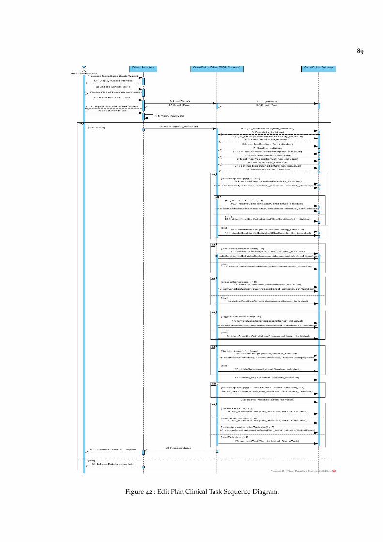
89
Figure 42.: Edit Plan Clinical Task Sequence Diagram.
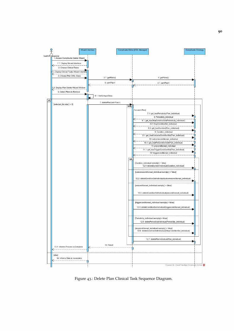
90
Figure 43.: Delete Plan Clinical Task Sequence Diagram.
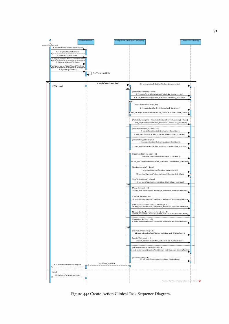
91
Figure 44.: Create Action Clinical Task Sequence Diagram.
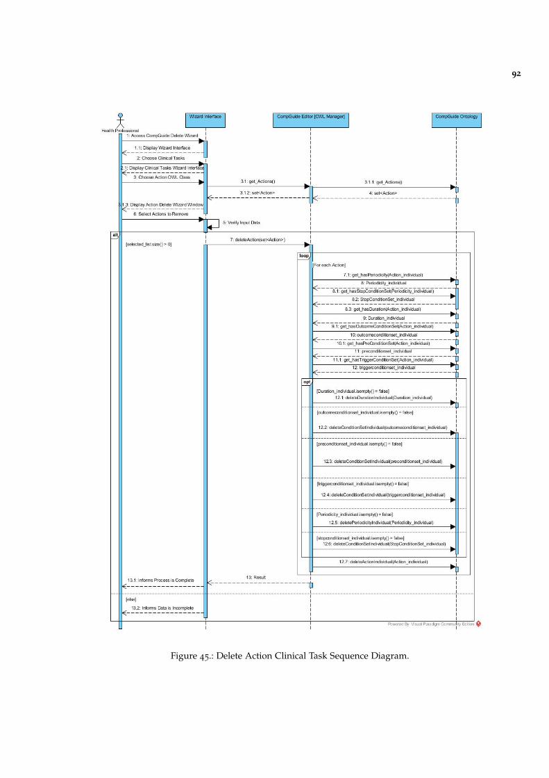
92
Figure 45.: Delete Action Clinical Task Sequence Diagram.

93
Figure 46.: Create Option Sequence Diagram.
Figure 47.: Edit Option Sequence Diagram.
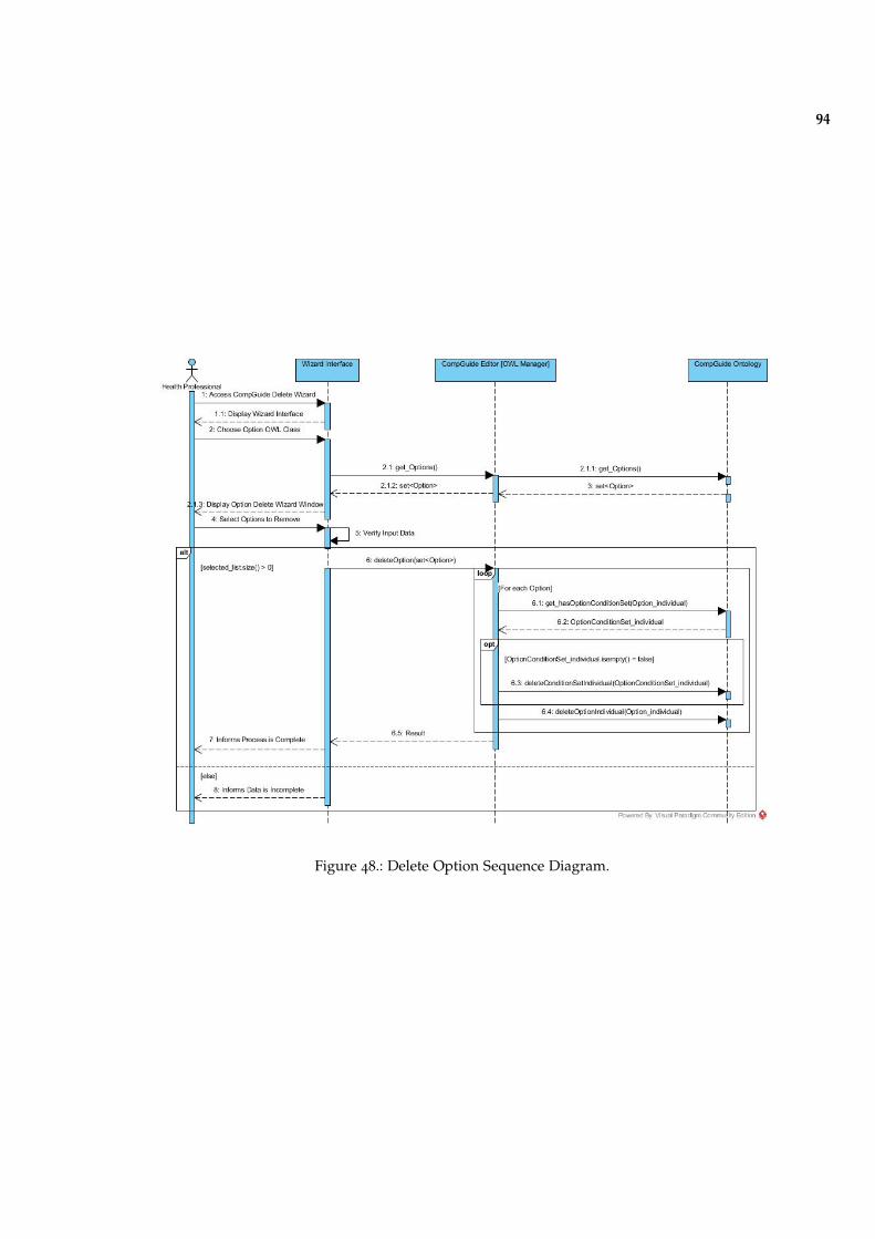
94
Figure 48.: Delete Option Sequence Diagram.
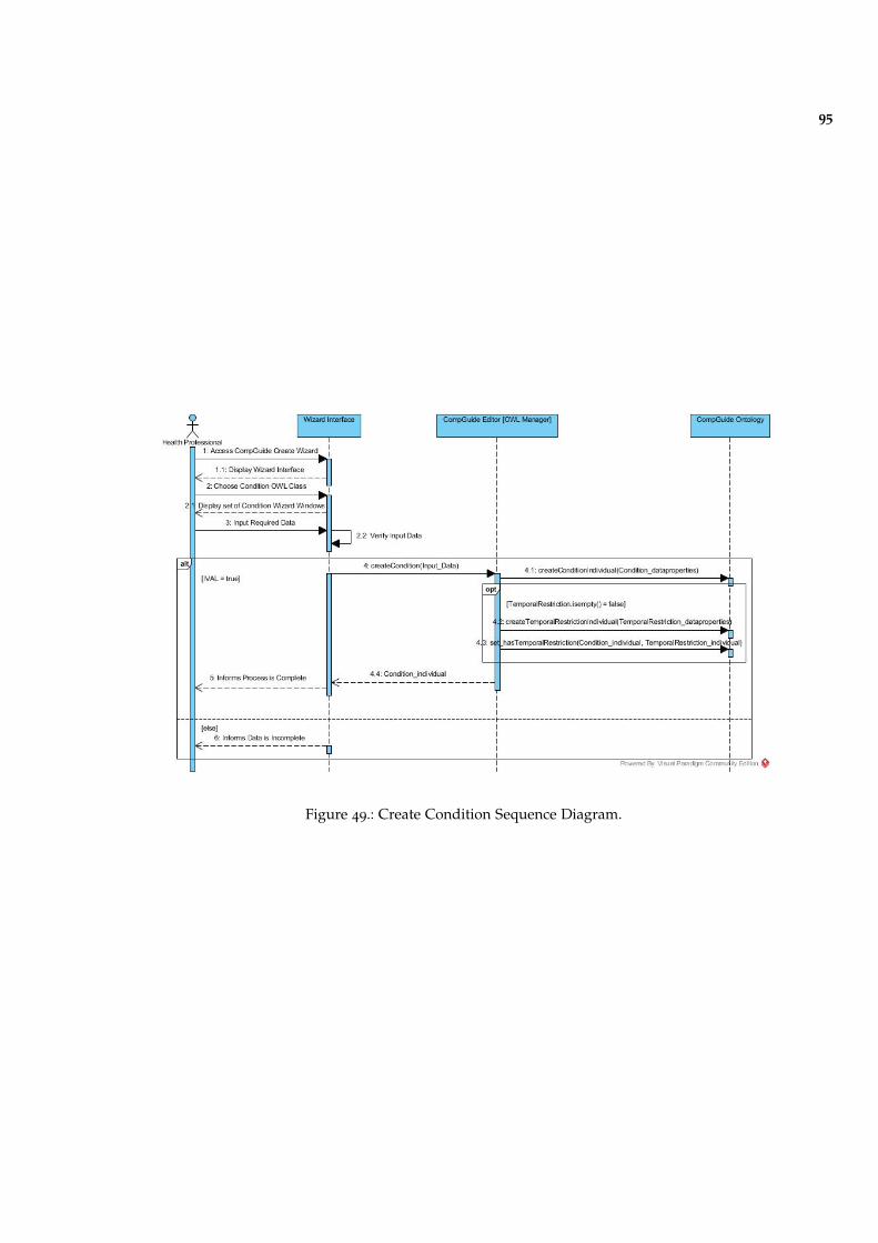
95
Figure 49.: Create Condition Sequence Diagram.
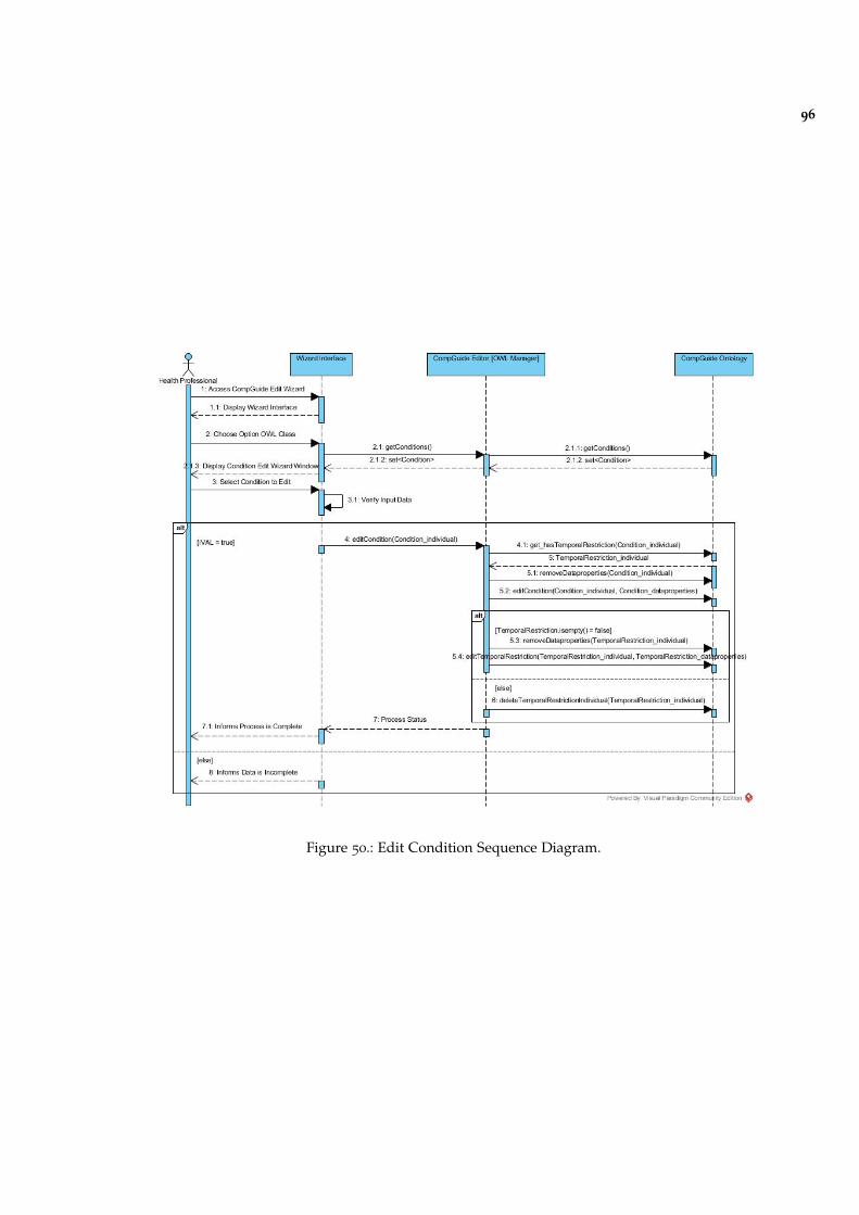
96
Figure 50.: Edit Condition Sequence Diagram.
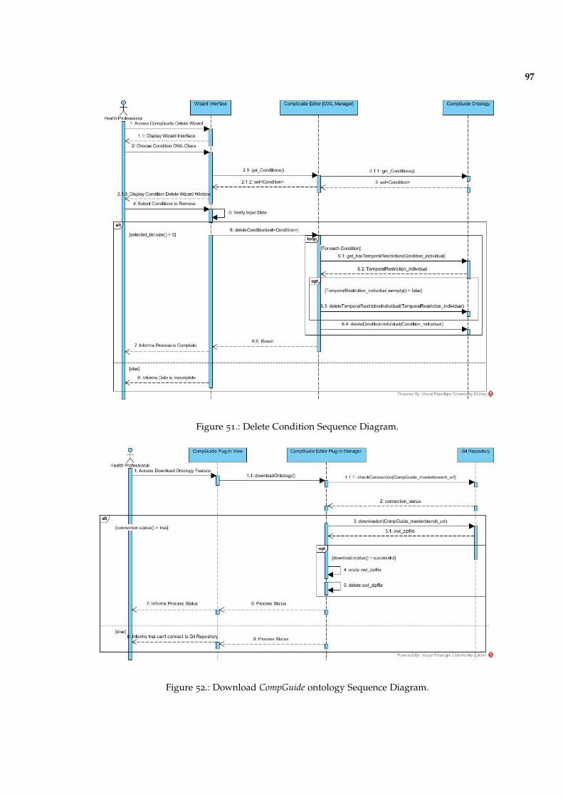
97
Figure 51.: Delete Condition Sequence Diagram.
Figure 52.: Download CompGuide ontology Sequence Diagram.
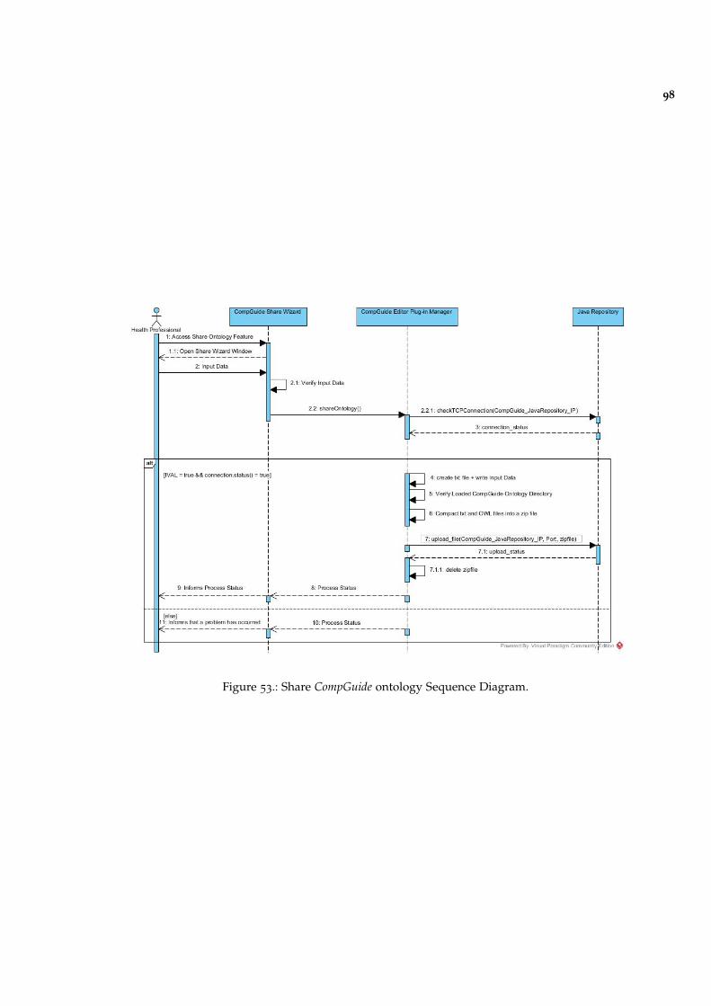
98
Figure 53.: Share CompGuide ontology Sequence Diagram.
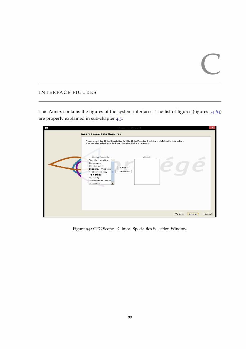
CI N T E R FA C E F I G U R E S
This Annex contains the figures of the system interfaces. The list of figures (figures 54-64)are properly explained in sub-chapter 4.5.
Figure 54.: CPG Scope - Clinical Specialties Selection Window.
99
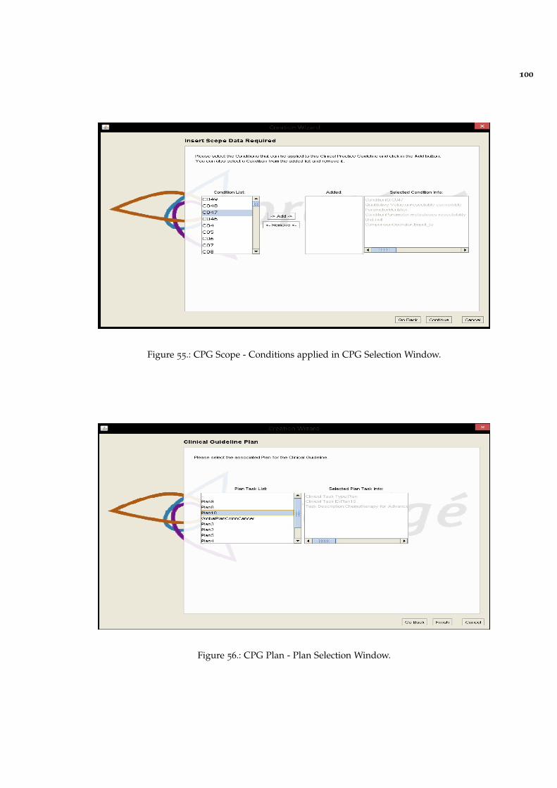
100
Figure 55.: CPG Scope - Conditions applied in CPG Selection Window.
Figure 56.: CPG Plan - Plan Selection Window.
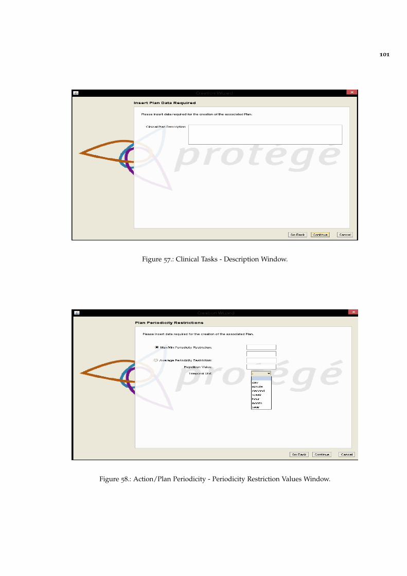
101
Figure 57.: Clinical Tasks - Description Window.
Figure 58.: Action/Plan Periodicity - Periodicity Restriction Values Window.
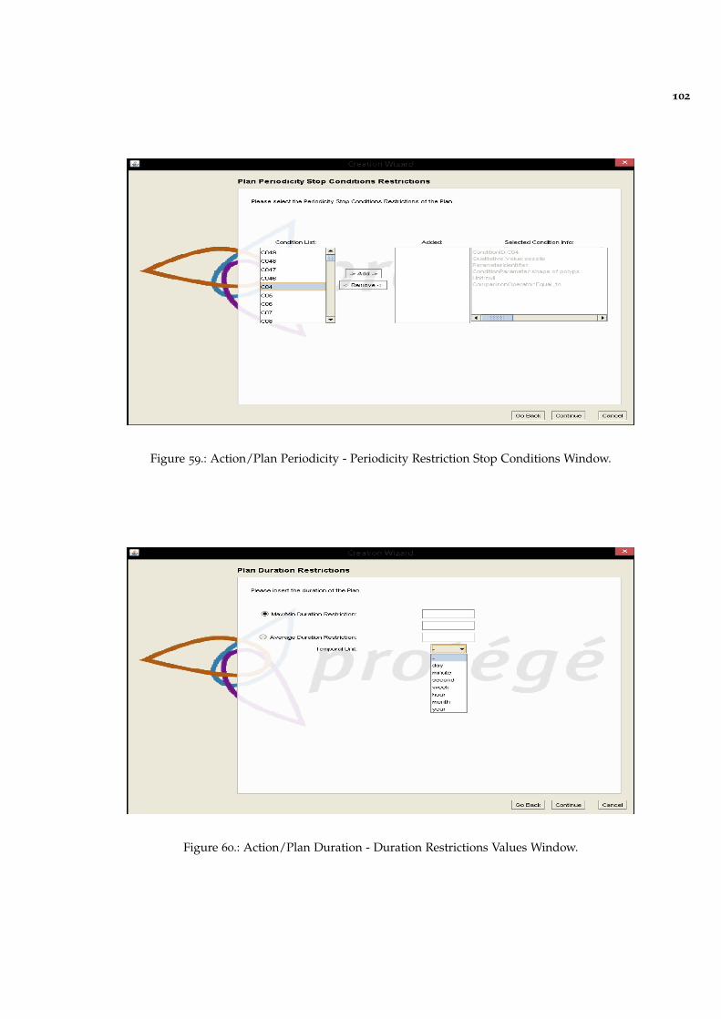
102
Figure 59.: Action/Plan Periodicity - Periodicity Restriction Stop Conditions Window.
Figure 60.: Action/Plan Duration - Duration Restrictions Values Window.
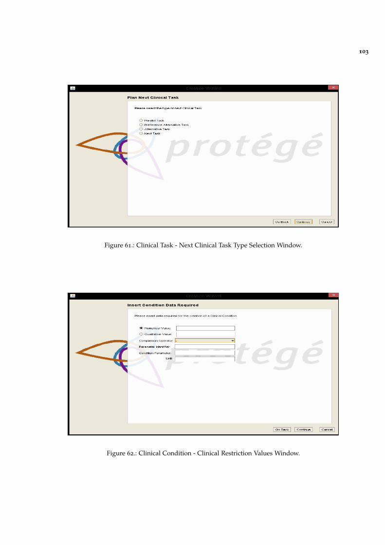
103
Figure 61.: Clinical Task - Next Clinical Task Type Selection Window.
Figure 62.: Clinical Condition - Clinical Restriction Values Window.
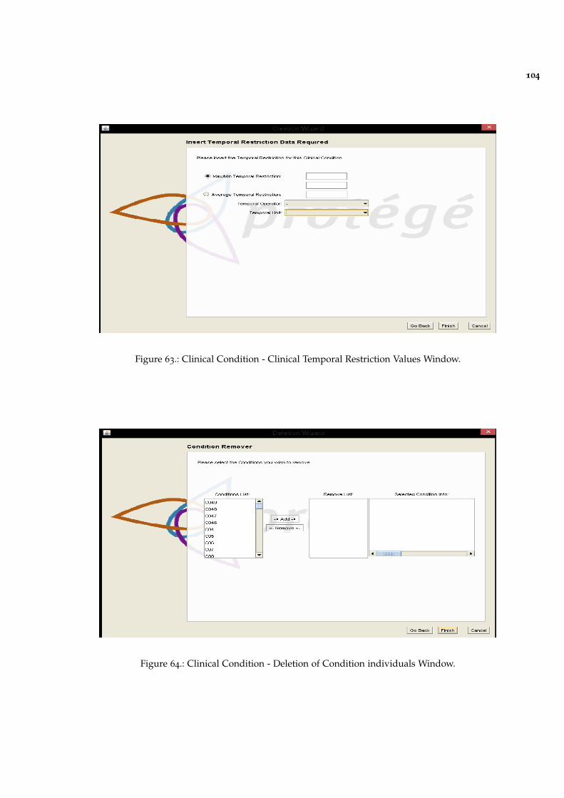
104
Figure 63.: Clinical Condition - Clinical Temporal Restriction Values Window.
Figure 64.: Clinical Condition - Deletion of Condition individuals Window.