Sun Cluster 3.2 Administration VC-ES-345
586
Sun Microsystems, Inc. UBRM05-104 500 Eldorado Blvd. Broomfield, CO 80021 U.S.A. Revision A StudentGuide Sun™ Cluster 3.2 Administration VC-ES-345 o n o t d u p l i c a t e o r d i s t r i b u t e w i t h o u t p e r i s s i o f r o S u i c r o s y s t e s , I n c U s e s u b j e c t t o l i c e s e
Transcript of Sun Cluster 3.2 Administration VC-ES-345
8/4/2019 Sun Cluster 3.2 Administration VC-ES-345
http://slidepdf.com/reader/full/sun-cluster-32-administration-vc-es-345 1/585
Sun Microsystems, Inc.UBRM05-104
500 Eldorado Blvd.Broomfield, CO 80021
U.S.A.
Revision A
StudentGuide
Sun™ Cluster 3.2 Administration
VC-ES-345

8/4/2019 Sun Cluster 3.2 Administration VC-ES-345
http://slidepdf.com/reader/full/sun-cluster-32-administration-vc-es-345 2/585
Do not duplicate or distribute without permission from Sun Microsystems, Inc. U
8/4/2019 Sun Cluster 3.2 Administration VC-ES-345
http://slidepdf.com/reader/full/sun-cluster-32-administration-vc-es-345 3/585
Please
Recycle
Copyright 2007 Sun Microsystems, Inc. 4150 Network Circle, Santa Clara, California 95054, U.S.A. All rights reserved.
This product or document is protected by copyright and distributed under licenses restricting its use, copying, distribution, anddecompilation. No part of this product or document may be reproduced in any form by any means without prior written authorization ofSun and its licensors, if any.
Third-party software, including font technology, is copyrighted and licensed from Sun suppliers.
Sun, Sun Microsystems, the Sun logo, Sun Fire, Solaris, Sun Enterprise, Solstice DiskSuite, JumpStart, Sun StorEdge, SunPlex, SunSolve, Java, and OpenBoot are trademarks or registered trademarks of Sun Microsystems, Inc. in the U.S. and other countries.
All SPARC trademarks are used under license and are trademarks or registered trademarks of SPARC International, Inc. in the U.S. andother countries. Products bearing SPARC trademarks are based upon an architecture developed by Sun Microsystems, Inc.
UNIX is a registered trademark in the U.S. and other countries, exclusively licensed through X/Open Company, Ltd.
Xylogics product is protected by copyright and licensed to Sun by Xylogics. Xylogics and Annex are trademarks of Xylogics, Inc.
Federal Acquisitions: Commercial Software – Government Users Subject to Standard License Terms and Conditions
Export Laws. Products, Services, and technical data delivered by Sun may be subject to U.S. export controls or the trade laws of othercountries. You will comply with all such laws and obtain all licenses to export, re-export, or import as may be required after delivery toYou. You will not export or re-export to entities on the most current U.S. export exclusions lists or to any country subject to U.S. embargo
or terrorist controlsas specified in the U.S. export laws. You willnot use or provide Products, Services, or technical data for nuclear, missile,or chemical biological weaponry end uses.
DOCUMENTATION IS PROVIDED “AS IS” AND ALL EXPRESS OR IMPLIED CONDITIONS, REPRESENTATIONS, ANDWARRANTIES, INCLUDING ANY IMPLIED WARRANTY OF MERCHANTABILITY, FITNESS FOR A PARTICULAR PURPOSEOR NON-INFRINGEMENT, ARE DISCLAIMED, EXCEPT TO THE EXTENT THAT SUCH DISCLAIMERS ARE HELD TO BELEGALLY INVALID.
THIS MANUAL IS DESIGNED TO SUPPORT AN INSTRUCTOR-LED TRAINING (ILT) COURSE AND IS INTENDED TO BEUSED FOR REFERENCE PURPOSES IN CONJUNCTION WITH THE ILT COURSE. THE MANUAL IS NOT A STANDALONETRAINING TOOL. USE OF THE MANUAL FOR SELF-STUDY WITHOUT CLASS ATTENDANCE IS NOT RECOMMENDED.
Export Commodity Classification Number (ECCN) assigned: 7 August 2006
8/4/2019 Sun Cluster 3.2 Administration VC-ES-345
http://slidepdf.com/reader/full/sun-cluster-32-administration-vc-es-345 4/585
Please
Recycle
Copyright 2007 Sun Microsystems Inc. 4150 Network Circle, Santa Clara, California 95054, Etats-Unis. Tous droits réservés.
Ce produit ou document est protégé par un copyright et distribué avec des licences qui en restreignent l’utilisation, la copie, la distribution,et la décompilation. Aucune partie de ce produit ou document ne peut être reproduite sous aucune forme, par quelque moyen que ce soit,sans l’autorisation préalable et écrite de Sun et de ses bailleurs de licence, s’il y en a.
Le logiciel détenu par des tiers, et qui comprend la technologie relative aux polices de caractères, est protégé par un copyright et licenciépar des fournisseurs de Sun.
Sun, SunMicrosystems, le logo Sun, SunFire, Solaris,Sun Enterprise, Solstice DiskSuite, JumpStart, Sun StorEdge, SunPlex, SunSolve,Java,et OpenBoot sont des marques de fabrique ou des marques déposées de Sun Microsystems, Inc. aux Etats-Unis et dans d’autres pays.
Toutes les marques SPARC sont utilisées sous licence sont des marques de fabrique ou des marques déposées de SPARC International, Inc.aux Etats-Unis et dans d’autres pays. Les produits portant les marques SPARC sont basés sur une architecture développée par SunMicrosystems, Inc.
UNIX est une marques déposée aux Etats-Unis et dans d’autres pays et licenciée exclusivement par X/Open Company, Ltd.
Législation en matière dexportations. Les Produits, Services et données techniques livrés par Sun peuvent être soumis aux contrôlesaméricains sur les exportations, ou à la législation commerciale dautres pays. Nous nous conformerons à lensemble de ces textes et nousobtiendrons toutes licences dexportation, de ré-exportation ou dimportation susceptibles dêtre requises après livraison à Vous. Vousnexporterez, ni ne ré-exporterez en aucun cas à des entités figurant sur les listes américaines dinterdiction dexportation les plus courantes,ni vers un quelconque pays soumis à embargo par les Etats-Unis, ou à des contrôles anti-terroristes, comme prévu par la législation
américaine en matièredexportations. Vous nutiliserez, ni ne fournirez les Produits, Services ou données techniques pour aucune utilisationfinale liée aux armes nucléaires, chimiques ou biologiques ou aux missiles.
LA DOCUMENTATION EST FOURNIE “EN L’ETAT” ET TOUTES AUTRES CONDITIONS, DECLARATIONS ET GARANTIESEXPRESSES OU TACITES SONT FORMELLEMENT EXCLUES, DANS LA MESURE AUTORISEE PAR LA LOI APPLICABLE, YCOMPRIS NOTAMMENT TOUTE GARANTIE IMPLICITE RELATIVE A LA QUALITE MARCHANDE, A L’APTITUDE A UNEUTILISATION PARTICULIERE OU A L’ABSENCE DE CONTREFAÇON.
CE MANUEL DE RÉFÉRENCE DOIT ÊTRE UTILISÉ DANS LE CADRE D’UN COURS DE FORMATION DIRIGÉ PAR UNINSTRUCTEUR (ILT). IL NE S’AGIT PAS D’UN OUTIL DE FORMATION INDÉPENDANT. NOUS VOUS DÉCONSEILLONS DEL’UTILISER DANS LE CADRE D’UNE AUTO-FORMATION.
Donotduplicate
ordistributewithoutpermissionfrom SunMicrosystems,Inc.Usesubject
tolicense.
8/4/2019 Sun Cluster 3.2 Administration VC-ES-345
http://slidepdf.com/reader/full/sun-cluster-32-administration-vc-es-345 5/585
viiCopyright 2006 SunMicrosystems, Inc. AllRightsReserved.SunServices, RevisionA
Table of Contents
About This Course ...........................................................Preface-xxiiiCourse Goals...................................................................... Preface-xxiiiCourse Map.........................................................................Preface-xxivTopics Not Covered............................................................Preface-xxvHow Prepared Are You?...................................................Preface-xxviIntroductions .....................................................................Preface-xxviiHow to Use Course Materials ....................................... Preface-xxviiiConventions........................................................................Preface-xxix
Icons ............................................................................Preface-xxix
Introducing Sun™ Cluster Hardware and Software......................1-1Objectives ........................................................................................... 1-1Relevance............................................................................................. 1-2Additional Resources ........................................................................ 1-3Defining Clustering ........................................................................... 1-4
High-Availability (HA) Platforms.......................................... 1-4Platforms for Scalable Applications ....................................... 1-5
Sun Cluster 3.2 Hardware and Software Environment............... 1-6Sun Cluster 3.2 Hardware Environment ........................................ 1-8
Cluster Host Systems................................................................ 1-9Cluster Transport Interface...................................................... 1-9Public Network Interfaces ..................................................... 1-10Boot Disks................................................................................. 1-11Administrative Workstation.................................................. 1-12Cluster in a Box ....................................................................... 1-19
Sun Cluster 3.2 Software Support.................................................. 1-21
Software Revisions.................................................................. 1-22Types of Applications in the Sun Cluster SoftwareEnvironment ..................................................................................... 1-25
Cluster-Unaware (Off-the-Shelf) Applications................... 1-25Sun Cluster 3.2 Software Data Service Support........................... 1-30
HA and Scalable Data Service Support ............................... 1-30Exploring the Sun Cluster Software HA Framework................. 1-32
Node Fault Monitoring and Cluster Membership............. 1-32
8/4/2019 Sun Cluster 3.2 Administration VC-ES-345
http://slidepdf.com/reader/full/sun-cluster-32-administration-vc-es-345 6/585
viii Sun™ Cluster 3.1 AdministrationCopyright2006 SunMicrosystems, Inc. AllRights Reserved.SunServices, RevisionA
Network Fault Monitoring .................................................... 1-32Application Traffic Striping................................................... 1-33
Global Storage Services ................................................................... 1-35Global Naming (DID Devices) .............................................. 1-35Global Devices......................................................................... 1-36
Device Files for Global Devices............................................. 1-38Global File Systems................................................................. 1-39Failover (Non-Global) File Systems in the Cluster............. 1-40
Exercise: Guided Tour of the Training Lab.................................. 1-41Preparation............................................................................... 1-41Task ........................................................................................... 1-41
Exercise Summary............................................................................ 1-42
Exploring Node Console Connectivity and the Cluster ConsoleSoftware............................................................................................ 2-1
Objectives ........................................................................................... 2-1Relevance............................................................................................. 2-2
Additional Resources ........................................................................ 2-3Accessing the Cluster Node Consoles ............................................ 2-4
Accessing Serial Port Consoles on Traditional Nodes......... 2-4Accessing Serial Port Node Consoles Using a Terminal
Concentrator ........................................................................... 2-5Sun Terminal Concentrator (Sun NTS).................................. 2-6Other Terminal Concentrators ................................................ 2-7Alternatives to a Terminal Concentrator (TC)...................... 2-8
Accessing the Node Consoles on Domain-Based Servers............ 2-9Sun Enterprise 10000 Servers .................................................. 2-9Sun Fire High-End Servers ...................................................... 2-9Sun Fire Midrange Servers ...................................................... 2-9
Describing Sun Cluster Console Software for anAdministration Workstation .......................................................... 2-11
Console Software Installation ............................................... 2-11Cluster Console Window Variations.................................... 2-11Cluster Console Tools Look and Feel................................... 2-13Cluster Console Common Window ..................................... 2-14Cluster Control Panel ............................................................. 2-15
Configuring Cluster Console Tools............................................... 2-16Configuring the /etc/clustersFile ..................................2-16
Exercise: Configuring the Administrative Console .................... 2-22Preparation............................................................................... 2-22Task 1 – Updating Host Name Resolution.......................... 2-23Task 2 – Installing the Cluster Console Software............... 2-23Task 3 – Verifying the Administrative ConsoleEnvironment ............................................................................ 2-24Task 4 – Configuring the /etc/clustersFile................... 2-24Task 5 – Configuring the /etc/serialportsFile ............ 2-25D
onotduplicate
ordistributewithoutpermissionfrom SunMicrosystems,Inc.Usesubject
tolicense.
8/4/2019 Sun Cluster 3.2 Administration VC-ES-345
http://slidepdf.com/reader/full/sun-cluster-32-administration-vc-es-345 7/585
ixCopyright 2006 SunMicrosystems, Inc. AllRightsReserved.SunServices, RevisionA
Task 6 – Starting the cconsoleTool.................................... 2-26Task 7 – Using the ccpControl Panel ..................................2-26
Exercise Summary............................................................................ 2-27
Preparing for Installation and Understanding Quorum Devices..3-1Objectives ........................................................................................... 3-1
Relevance............................................................................................. 3-2Additional Resources ........................................................................ 3-3Configuring Cluster Servers............................................................. 3-4
Boot Device Restrictions .......................................................... 3-4Boot Disk JumpStart™ Software Profile................................ 3-5Server Hardware Restrictions ................................................. 3-5
Configuring Cluster Storage Connections ..................................... 3-7Cluster Topologies.................................................................... 3-7Clustered Pairs Topology ........................................................ 3-8Single-Node Cluster Topology ............................................. 3-14
Describing Quorum Votes and Quorum Devices ....................... 3-15
Why Have Quorum Voting at All?....................................... 3-15Failure Fencing ........................................................................ 3-16Amnesia Prevention ............................................................... 3-16Quorum Mathematics and Consequences .......................... 3-17Two-Node Cluster Quorum Devices ................................... 3-18Clustered-Pair Quorum Disk Devices ................................. 3-19Pair+N Quorum Disks ........................................................... 3-20N+1 Quorum Disks................................................................. 3-21Quorum Devices in the Scalable Storage Topology........... 3-22
Quorum Server Quorum Devices.................................................. 3-26Preventing Cluster Amnesia With Persistent Reservations....... 3-28
SCSI-2 and SCSI-3 Reservations............................................ 3-31SCSI-3 Persistent Group Reservation (PGR) ....................... 3-32SCSI-3 PGR Scenario With More Than Two Nodes........... 3-32NAS Quorum and Quorum Server PersistentReservations............................................................................. 3-34Intentional Reservation Delays for Partitions With Fewer
Than Half of the Nodes....................................................... 3-34Data Fencing ..................................................................................... 3-36Configuring a Cluster Interconnect............................................... 3-37
Point-to-Point Cluster Interconnect...................................... 3-37Switch-based Cluster Interconnect....................................... 3-38Cluster Transport Interface Addresses and Netmask ....... 3-38Choosing the Cluster Transport Netmask Based on
Anticipated Nodes and Private Subnets........................... 3-39Identifying Public Network Adapters .......................................... 3-43Configuring Shared Physical Adapters ........................................ 3-44
Configuring the Public Network .......................................... 3-44
8/4/2019 Sun Cluster 3.2 Administration VC-ES-345
http://slidepdf.com/reader/full/sun-cluster-32-administration-vc-es-345 8/585
x Sun™ Cluster 3.1 AdministrationCopyright2006 SunMicrosystems, Inc. AllRights Reserved.SunServices, RevisionA
Allocating a Different VLAN ID for the PrivateNetwork.................................................................................... 3-44
Exercise: Preparing for Installation ............................................... 3-45Preparation............................................................................... 3-45Task 1 – Verifying the Solaris OS.......................................... 3-45
Task 3 – Selecting Quorum Devices ..................................... 3-46Task 5 – Selecting Public Network Interfaces..................... 3-48Exercise Summary............................................................................ 3-50
Installing and Configuring the Sun Cluster Software
Framework........................................................................................ 4-1Objectives ........................................................................................... 4-1Relevance............................................................................................. 4-2Additional Resources ........................................................................ 4-3Sun Cluster Software Installation and Configuration .................. 4-4
Introduction to Sun Cluster Package Installation ................ 4-4
Sun Cluster Packaging ............................................................. 4-4Spooling Together CDROM 1of 2 and CDROM 2 of 2 ........ 4-5Patches for the OS and for the Sun Cluster Software .......... 4-6
Installing the Sun Cluster Packages With the Java™ ESInstaller ................................................................................................ 4-7
Prerequisites for Installing Sun Cluster Software ................ 4-7Configuring the User root Environment............................ 4-14
Sun Cluster Framework Configuration ........................................ 4-15Understanding the installmodeFlag ................................ 4-15Automatic Quorum Configuration (Two-NodeCluster Only) ........................................................................... 4-16
Automatic Reset of installmodeWithout QuorumDevices (Clusters With More Than Two Nodes Only)...... 4-17Configuration Information Required to Runscinstall................................................................................ 4-17Variations in Interactive scinstall.................................... 4-21Configuring the Entire Cluster at Once ............................... 4-21Typical Installation Compared to Custom Installation..... 4-22
Configuring Using All-at-Once and Typical Modes:Example ............................................................................................. 4-23
All-at-Once Introduction and Choosing TypicalCompared to Custom Installation ........................................ 4-24
Configuring Using One-at-a-Time and Custom Modes:Example (First Node) ...................................................................... 4-31Configuring Additional Nodes for One-at-a-Time Method:
Example.......................................................................................... 4-42Solaris OS Files and Settings Automatically Configured byscinstall...................................................................................... 4-48
Changes to the /etc/hosts File........................................... 4-48Changes to the /etc/nsswitch.confFile......................... 4-48D
onotduplicate
ordistributewithoutpermissionfrom SunMicrosystems,Inc.Usesubject
tolicense.
8/4/2019 Sun Cluster 3.2 Administration VC-ES-345
http://slidepdf.com/reader/full/sun-cluster-32-administration-vc-es-345 9/585
xiCopyright 2006 SunMicrosystems, Inc. AllRightsReserved.SunServices, RevisionA
Modifying /etc/hostname.xxx Files to Include IPMP .. 4-49Modifying the /etc/vfstabFile ........................................4-50Inserting the /etc/notrouterFile...................................... 4-50Modifying the local-mac-address?EEPROMvariable ..................................................................................... 4-50
Automatic Quorum Configuration andinstallmode
Resetting............................................................................................ 4-51Manual Quorum Selection.............................................................. 4-52
Verifying DID Devices ........................................................... 4-52Choosing Quorum and Resetting the installmodeAttribute (Two-Node Cluster) .............................................. 4-53
Performing Post-Installation Verification..................................... 4-58Verifying General Cluster Status.......................................... 4-58
Exercise: Installing the Sun Cluster Server Software.................. 4-63Task 1 – Verifying the Boot Disk .......................................... 4-63Task 2 – Verifying the Environment .................................... 4-64
Task 3 – Updating Local Name Resolution......................... 4-64Task 4 – Installing the Sun Cluster Packages...................... 4-65Task 5 – Configuring a New Cluster –The All-Nodes-at-Once Method ........................................... 4-66Task 6 – Configuring a New Cluster – The
One-Node-at-a-Time Method............................................. 4-67Task 7 – Verifying an Automatically Selected QuorumDevice (Two-Node Cluster)................................................... 4-69Task 8 – Configuring a Quorum Device (Three-NodeCluster or Two-Node Cluster With No AutomaticSelection) .................................................................................. 4-70
Exercise Summary............................................................................ 4-72Performing Basic Cluster Administration......................................5-1
Objectives ........................................................................................... 5-1Relevance............................................................................................. 5-2Additional Resources ........................................................................ 5-3Identifying Cluster Daemons........................................................... 5-4Using Cluster Commands................................................................. 5-7
Commands Relating to Basic Cluster Administration ........ 5-7Additional Commands............................................................. 5-8Cluster Command Self-Documentation ................................ 5-8
Viewing and Administering Cluster Global Properties............. 5-10Renaming the Cluster............................................................. 5-10Setting Other Cluster Properties........................................... 5-11
Viewing and Administering Nodes .............................................. 5-12Viewing Node Status and Configuration............................ 5-12Modifying Node Information................................................ 5-13Viewing Software Release Information on a Node............ 5-14
Viewing and Administering Quorum .......................................... 5-16
8/4/2019 Sun Cluster 3.2 Administration VC-ES-345
http://slidepdf.com/reader/full/sun-cluster-32-administration-vc-es-345 10/585
xii Sun™ Cluster 3.1 AdministrationCopyright2006 SunMicrosystems, Inc. AllRights Reserved.SunServices, RevisionA
Viewing Quorum Status and Configuration....................... 5-16Adding and Removing (and Replacing) QuorumDevices...................................................................................... 5-17Installing a Quorum Server (Outside the Cluster) ............. 5-17Adding a Quorum Server Device to a Cluster.................... 5-18
Registering NAS Devices and Choosing a NASDevice as a Quorum Device .................................................. 5-19Registering NAS Mounted Directories (for DataFencing) .................................................................................... 5-20
Viewing and Administering Disk Paths and Settings ................ 5-22Displaying Disk Paths ............................................................ 5-22Displaying Disk Path Status.................................................. 5-23Changing Disk Path Monitoring Settings............................ 5-24Unmonitoring All Non-Shared Devices andEnabling reboot_on_path_failure..................................5-25Viewing Settings Related to SCSI-2 and SCSI-3 Disk
Reservations.......................................................................... 5-26Modifying Properties to use SCSI-3 Reservations forDisks With Two Paths ............................................................ 5-26
Viewing and Administering Interconnect Components............ 5-29Viewing Interconnect Status.................................................. 5-29Adding New Private Networks............................................ 5-29
Using the clsetupCommand ....................................................... 5-31Sun Cluster Manager....................................................................... 5-33
Logging Into the Sun Java Web Console ............................. 5-34Accessing Sun Cluster Manager ........................................... 5-35
Running Cluster Commands as Non-root User or Role
Using Role Based Access Control (RBAC) ................................... 5-38Controlling Clusters ........................................................................ 5-39Starting and Stopping Cluster Nodes .................................. 5-39Booting a SPARC Platform Machine With the -x
Command................................................................................. 5-41Maintenance Mode Example................................................. 5-45
Modifying Private Network Address and Netmask .................. 5-46Exercise: Performing Basic Cluster Administration ................... 5-48
Preparation............................................................................... 5-48Task 1 – Verifying Basic Cluster Configuration andStatus......................................................................................... 5-48
Task 2 – Reassigning a Quorum Device .............................. 5-49Task 3 – Adding a Quorum Server Quorum Device ......... 5-50Task 5 – Preventing Cluster Amnesia .................................. 5-51Task 6 – Changing the Cluster Private IP AddressRange ........................................................................................ 5-52Task 7 (Optional) – Navigating Sun ClusterManager.................................................................................... 5-53
Exercise Summary............................................................................ 5-54Donotduplicate
ordistributewithoutpermissionfrom SunMicrosystems,Inc.Usesubject
tolicense.
8/4/2019 Sun Cluster 3.2 Administration VC-ES-345
http://slidepdf.com/reader/full/sun-cluster-32-administration-vc-es-345 11/585
xiiiCopyright 2006 SunMicrosystems, Inc. AllRightsReserved.SunServices, RevisionA
Using VERITAS Volume Manager With Sun Cluster Software.....6-1Objectives ........................................................................................... 6-1Relevance............................................................................................. 6-2Additional Resources ........................................................................ 6-3Introducing VxVM in the Sun Cluster Software
Environment ....................................................................................... 6-4Exploring VxVM Disk Groups......................................................... 6-5Shared Storage Disk Groups ................................................... 6-5VERITAS Management on Local Disks (Optional inVxVM 4.x and Above) .............................................................. 6-5Sun Cluster Management of Disk Groups ............................ 6-7Sun Cluster Global Devices Within a Disk Group............... 6-7VxVM Cluster Feature Used Only for Oracle RAC ............. 6-8
Initializing a VERITAS Volume Manager Disk ............................. 6-9Traditional Solaris OS Disks and Cross-Platform DataSharing (CDS) Disks ................................................................. 6-9
Reviewing the Basic Objects in a Disk Group.............................. 6-11Disk Names or Media Names ............................................... 6-11Subdisk ..................................................................................... 6-11Plex............................................................................................ 6-11Volume ..................................................................................... 6-12Layered Volume...................................................................... 6-12
Exploring Volume Requirements in the Sun ClusterEnvironment ..................................................................................... 6-13
Simple Mirrors......................................................................... 6-13Mirrored Stripe (Mirror-Stripe) ............................................ 6-14Striped Mirrors (Stripe-Mirror)............................................. 6-15
Dirty Region Logs for Volumes in the Cluster ................... 6-16Viewing the Installation and bootdg/rootdgRequirementsin the Sun Cluster Environment .................................................... 6-17
Requirements for bootdg/rootdg....................................... 6-17DMP Restrictions in Sun Cluster 3.2 .................................... 6-18Installing Supported Multipathing Software...................... 6-19
Installing VxVM in the Sun Cluster 3.2 SoftwareEnvironment ..................................................................................... 6-20
Using the installer or installvmUtility........................ 6-20Manually Using vxdiskadm to Encapsulate theOS Disk ..................................................................................... 6-24
Configuring a Pre-Existing VxVM for Sun Cluster 3.2Software................................................................................. 6-24
Creating Shared Disk Groups and Volumes................................ 6-26Listing Available Disks .......................................................... 6-26Initializing Disks and Putting Them Into a New DiskGroup........................................................................................ 6-27Verifying Disk Groups Imported on a Node ...................... 6-27Building a Mirrored Striped Volume (RAID 0+1).............. 6-29
8/4/2019 Sun Cluster 3.2 Administration VC-ES-345
http://slidepdf.com/reader/full/sun-cluster-32-administration-vc-es-345 12/585
xiv Sun™ Cluster 3.1 AdministrationCopyright2006 SunMicrosystems, Inc. AllRights Reserved.SunServices, RevisionA
Building a Striped Mirrored Volume (RAID 1+0).............. 6-30Examining Hot Relocation.............................................................. 6-31Registering VxVM Disk Groups .................................................... 6-32
Using the clsetup Command to Register DiskGroups ...................................................................................... 6-33
Viewing and Controlling Registered Device Groups........ 6-34Managing VxVM Device Groups .................................................. 6-35Resynchronizing Device Groups .......................................... 6-35Making Other Changes to Device Groups .......................... 6-35Putting a Device Group Offline and Back Online.............. 6-35
Using Global and Failover File Systems on VxVMVolumes............................................................................................. 6-37
Creating File Systems ............................................................. 6-37Mounting File Systems........................................................... 6-37
Mirroring the Boot Disk With VxVM............................................ 6-39ZFS as Failover File System Only .................................................. 6-40
ZFS Includes Volume Management Layer.......................... 6-40ZFS Removes Need for /etc/vfstabEntries ....................6-40Example: Creating a Mirrored Pool and SomeFilesystems............................................................................... 6-40
Exercise: Configuring Volume Management............................... 6-42Task 1 – Selecting Disk Drives .............................................. 6-44Task 4 – Adding vxio on Any Non-Storage Nodeon Which You Have Not Installed VxVM........................... 6-46Task 5 – Rebooting All Nodes............................................... 6-46Task 7 – Registering Demonstration Disk Groups............. 6-48Task 8 – Creating a Global nfs File System........................ 6-50
Task 9 – Creating a Global web File System........................ 6-50Task 10 – Testing Global File Systems ................................. 6-51Task 11 – Managing Disk Device Groups ........................... 6-51Task 12 (Optional) – Viewing and Managing VxVMDevice Groups Using Sun Cluster Manager....................... 6-54Task 13 (Optional) – Encapsulating the Boot Disk on aCluster Node............................................................................ 6-54
Exercise Summary............................................................................ 6-56
Using Solaris Volume Manager With Sun Cluster Software........ 7-1Objectives ........................................................................................... 7-1Relevance............................................................................................. 7-2Additional Resources ........................................................................ 7-3Viewing Solaris Volume Manager in the Sun ClusterSoftware Environment ...................................................................... 7-4Exploring Solaris Volume Manager Disk SpaceManagement ....................................................................................... 7-5
Solaris Volume Manager Partition-Based Disk SpaceManagement ........................................................................... 7-5D
onotduplicate
ordistributewithoutpermissionfrom SunMicrosystems,Inc.Usesubject
tolicense.
8/4/2019 Sun Cluster 3.2 Administration VC-ES-345
http://slidepdf.com/reader/full/sun-cluster-32-administration-vc-es-345 13/585
xvCopyright 2006 SunMicrosystems, Inc. AllRightsReserved.SunServices, RevisionA
Solaris Volume Manager Disk Space ManagementWith Soft Partitions................................................................... 7-6
Exploring Solaris Volume Manager Disksets ................................ 7-9Solaris Volume Manager Multi-Owner Disksets (forOracle RAC)...................................................................................... 7-10
Using Solaris Volume Manager Database Replicas (metadb
Replicas) ......................................................................................... 7-11Local Replica Management.................................................... 7-11Shared Diskset Replica Management................................... 7-12Shared Diskset Replica Quorum Mathematics................... 7-12Shared Diskset Mediators...................................................... 7-12
Installing Solaris Volume Manager and Tuning themd.conf File...................................................................................... 7-14
Modifying the md.conf File (Solaris 9 OS Only)................ 7-14Initializing the Local metadbReplicas on Boot Disk andMirror................................................................................................. 7-15
Using DIDs Compared to Using Traditional c#t#d#........ 7-15Adding the Local metadbReplicas to the Boot Disk ......... 7-15Repartitioning a Mirror Boot Disk and AddingmetadbReplicas....................................................................... 7-16Using the metadb or metadb -iCommand toVerify metadbReplicas .......................................................... 7-16
Creating Shared Disksets and Mediators ..................................... 7-17Automatic Repartitioning and metadbPlacement onShared Disksets ....................................................................... 7-18
Using Shared Diskset Disk Space .................................................. 7-20Building Volumes in Shared Disksets With Soft
Partitions of Mirrors ........................................................................ 7-21Using Solaris Volume Manager Status Commands.................... 7-22Checking Volume Status........................................................ 7-22
Managing Solaris Volume Manager Disksets and SunCluster Device Groups .................................................................... 7-24Managing Solaris Volume Manager Device Groups .................. 7-26
Device Group Resynchronization......................................... 7-26Other Changes to Device Groups......................................... 7-26Putting a Device Group Offline ............................................ 7-26
Using Global and Failover File Systems on Shared DisksetVolumes.......................................................................................... 7-27
Creating File Systems ............................................................. 7-27Mounting File Systems........................................................... 7-27
Using Solaris Volume Manager to Mirror the Boot Disk........... 7-28Verifying Partitioning and Local metadbs..........................7-28Building Volumes for Each Partition Except for Root....... 7-29Building Volumes for Root Partition ................................... 7-29Running the Commands........................................................ 7-30Rebooting and Attaching the Second Submirror ............... 7-31
8/4/2019 Sun Cluster 3.2 Administration VC-ES-345
http://slidepdf.com/reader/full/sun-cluster-32-administration-vc-es-345 14/585
xvi Sun™ Cluster 3.1 AdministrationCopyright2006 SunMicrosystems, Inc. AllRights Reserved.SunServices, RevisionA
ZFS as Failover File System Only .................................................. 7-32ZFS Includes Volume Management Layer.......................... 7-32ZFS Removes Need for /etc/vfstabEntries ....................7-32Example: Creating a Mirrored Pool and someFilesystems............................................................................... 7-32
Exercise: Configuring Solaris Volume Manager ......................... 7-34Preparation............................................................................... 7-34Task 1 – Initializing the Solaris Volume ManagerLocal metadbReplicas ............................................................ 7-36Task 2 – Selecting the Solaris Volume Manager DemoVolume Disk Drives................................................................ 7-37Task 3 – Configuring Solaris Volume ManagerDisksets..................................................................................... 7-38Task 4 – Configuring Solaris Volume ManagerDemonstration Volumes ........................................................ 7-39Task 5 – Creating a Global nfs File System........................ 7-40
Task 6 – Creating a Global web File System........................ 7-41Task 8 – Managing Disk Device Groups ............................. 7-42Task 9 – Viewing and Managing Solaris VolumeManager Device Groups Using Sun Cluster Manager ...... 7-43Task 10 (Optional) – Managing and Mirroring theBoot Disk With Solaris Volume Manager............................ 7-43
Exercise Summary............................................................................ 7-46
Managing the Public Network With IPMP ...................................... 8-1Objectives ........................................................................................... 8-1Relevance............................................................................................. 8-2Additional Resources ........................................................................ 8-3Introducing IPMP .............................................................................. 8-4Describing General IPMP Concepts................................................ 8-5
Defining IPMP Group Requirements..................................... 8-5Configuring Standby Adapters in a Group........................... 8-7
Examining IPMP Group Examples ................................................. 8-8Single IPMP Group With Two Members and NoStandby....................................................................................... 8-8Single IPMP Group With Three Members Including aStandby....................................................................................... 8-9Two IPMP Groups on Different Subnets............................... 8-9Two IPMP Groups on the Same Subnet .............................. 8-10
Describing IPMP .............................................................................. 8-11Network Path Failure Detection ........................................... 8-11Network Path Failover ........................................................... 8-12Network Path Failback........................................................... 8-12
Configuring IPMP............................................................................ 8-13Examining New ifconfigOptions for IPMP.................... 8-13
Donotduplicate
ordistributewithoutpermissionfrom SunMicrosystems,Inc.Usesubject
tolicense.
8/4/2019 Sun Cluster 3.2 Administration VC-ES-345
http://slidepdf.com/reader/full/sun-cluster-32-administration-vc-es-345 15/585
xviiCopyright 2006 SunMicrosystems, Inc. AllRightsReserved.SunServices, RevisionA
Putting Test Addresses on Physical or VirtualInterfaces .................................................................................. 8-14Using ifconfigCommands to Configure IPMP .............. 8-14Configuring the /etc/hostname.xxx Files for IPMP.......8-15Using IPV6 Test Address Only.............................................. 8-16
Performing Failover and Failback Manually ............................... 8-18Configuring IPMP in the Sun Cluster 3.2 Environment............. 8-19Configuring IPMP Before or After Cluster Installation .... 8-19Using Same Group Names on Different Nodes ................. 8-19Understanding Standby and Failback ................................. 8-20
Integrating IPMP Into the Sun Cluster 3.2 SoftwareEnvironment ..................................................................................... 8-21
Capabilities of the pnmdDaemon in Sun Cluster 3.2Software.................................................................................... 8-21Summary of IPMP Cluster Integration................................ 8-22
Exercise: Configuring and Testing IPMP ..................................... 8-24
Preparation............................................................................... 8-24Task 1 – Verifying the local-mac-address?Variable ....8-24Task 2 – Verifying the Adapters for the IPMP Group....... 8-25Task 3 – Verifying or Entering Test Addresses inthe /etc/hostsFile ............................................................... 8-25Task 4 – Creating /etc/hostname.xxx Files .....................8-26Task 6 – Verifying IPMP Failover and Failback ................. 8-27
Introducing Data Services, Resource Groups, and HA-NFS........9-1Objectives ........................................................................................... 9-1Relevance............................................................................................. 9-2Additional Resources ........................................................................ 9-3Introducing Data Services in the Cluster........................................ 9-4
Solaris 10 OS Non-Global Zones Act as Virtual Nodesfor Data Services........................................................................ 9-4Off-the-Shelf Application......................................................... 9-4Sun Cluster 3.2 Software Data Service Agents ..................... 9-6
Reviewing Components of a Data Service Agent ......................... 9-7Fault Monitor Components ..................................................... 9-7
Introducing Data Service Packaging, Installation, andRegistration......................................................................................... 9-8
Data Service Packages and Resource Types.......................... 9-8Introducing Resources, Resource Groups, and the ResourceGroup Manager .................................................................................. 9-9
All Configuration Performed in the Global Zone ................ 9-9Resources.................................................................................. 9-10Resource Groups..................................................................... 9-10Resource Group Manager...................................................... 9-12
Describing Failover Resource Groups .......................................... 9-13Resources and Resource Types ............................................. 9-14
8/4/2019 Sun Cluster 3.2 Administration VC-ES-345
http://slidepdf.com/reader/full/sun-cluster-32-administration-vc-es-345 16/585
xviii Sun™ Cluster 3.1 AdministrationCopyright2006 SunMicrosystems, Inc. AllRights Reserved.SunServices, RevisionA
Resource Type Versioning..................................................... 9-14Using Special Resource Types........................................................ 9-15
The SUNW.LogicalHostnameResource Type..................... 9-15The SUNW.SharedAddressResource Type......................... 9-15Guidelines for Using Global and Failover File
Systems..................................................................................... 9-17HAStoragePlus and ZFS ........................................................ 9-18Generic Data Service............................................................... 9-18
Understanding Resource Dependencies and ResourceGroup Dependencies....................................................................... 9-20
Resource Group Dependencies............................................. 9-21Configuring Resource and Resource Groups ThroughProperties .......................................................................................... 9-22
Standard Resource Properties............................................... 9-22Some Significant Standard Resource Properties ................ 9-23Resource Group Properties.................................................... 9-25
Some Significant Resource Group Properties..................... 9-26Specifying Non-Global Zone Names in Place of NodeNames ................................................................................................ 9-28Using the clresourcetype (clrt) Command ...........................9-29
Registering Resource Types .................................................. 9-29Unregistering Types ............................................................... 9-30
Configuring Resource Groups Using the clresourcegroup(clrg) Command .......................................................................... 9-31
Displaying Group Configuration Information................... 9-31Configuring a LogicalHostnameor a SharedAddressResource ............................................................................................ 9-33
Examples of Using clrslh to Add a LogicalHostname.. 9-33Configuring Other Resources Using the clresource (clrs)Command....................................................................................... 9-34
Displaying Resource Configuration Information............... 9-34Complete Resource Group Example for NFS .............................. 9-36Controlling the State of Resources and Resource Groups ......... 9-38
Introduction to Resource Group State ................................. 9-38Introduction to Resource State.............................................. 9-38
Suspended Resource Groups ......................................................... 9-42Displaying Resource and Resource Group Status Usingthe clrg status and clrs statusCommands ....................... 9-43
Example of Status Commands for a Single FailoverApplication ........................................................................... 9-43
Using the clsetupUtility for Resource and ResourceGroup Operations ............................................................................ 9-44Using the Data Service Wizards in clsetup and SunCluster Manager............................................................................... 9-45Exercise: Installing and Configuring HA-NFS ............................ 9-46
Preparation............................................................................... 9-46Donotduplicate
ordistributewithoutpermissionfrom SunMicrosystems,Inc.Usesubject
tolicense.
8/4/2019 Sun Cluster 3.2 Administration VC-ES-345
http://slidepdf.com/reader/full/sun-cluster-32-administration-vc-es-345 17/585
xixCopyright 2006 SunMicrosystems, Inc. AllRightsReserved.SunServices, RevisionA
Task 1 – Installing and Configuring the HA-NFSAgent and Server .................................................................... 9-47Task 2 – Registering and Configuring the Sun Cluster
HA-NFS Data Services ........................................................ 9-49Task 4 – Observing Sun Cluster HA-NFS Failover
Behavior.................................................................................... 9-51Task 5 – Generating Cluster Failures and ObservingBehavior of the NFS Failover ................................................ 9-52Task 9– Viewing and Managing Resources andResource Groups Using Sun Cluster Manager................... 9-57
Exercise Summary............................................................................ 9-58
Configuring Scalable Services and Advanced Resource GroupRelationships..................................................................................10-1
Objectives ......................................................................................... 10-1Relevance........................................................................................... 10-2Additional Resources ...................................................................... 10-3
Using Scalable Services and Shared Addresses........................... 10-4Exploring Characteristics of Scalable Services............................. 10-5
File and Data Access............................................................... 10-5File Locking for Writing Data ............................................... 10-5
Using the SharedAddressResource............................................. 10-6Client Affinity.......................................................................... 10-6Load-Balancing Weights ........................................................ 10-6
Exploring Resource Groups for Scalable Services....................... 10-7Understanding Properties for Scalable Groups andServices .............................................................................................. 10-9
The Desired_primariesand Maximum_primaries
Properties .............................................................................. 10-9The Load_balancing_policyProperty............................. 10-9The Load_balancing_weightsProperty........................... 10-9The Resource_dependenciesProperty........................... 10-10
Adding Auxiliary Nodes for a SharedAddressProperty....... 10-11Reviewing Command Examples for a Scalable Service ........... 10-12Controlling Scalable Resources and Resource Groups............. 10-13
Resource Group Operations................................................ 10-13Fault Monitor Operations .................................................... 10-14
Using the clrg status and clrs status Commandsfor a Scalable Application ............................................................. 10-15Advanced Resource Group Relationships ................................. 10-16
Weak Positive Affinities and Weak NegativeAffinities................................................................................. 10-16Strong Positive Affinities ..................................................... 10-17Strong Positive Affinity With Failover Delegation .......... 10-18
Exercise: Installing and Configuring Sun Cluster ScalableService for Apache ......................................................................... 10-20
8/4/2019 Sun Cluster 3.2 Administration VC-ES-345
http://slidepdf.com/reader/full/sun-cluster-32-administration-vc-es-345 18/585
xx Sun™ Cluster 3.1 AdministrationCopyright2006 SunMicrosystems, Inc. AllRights Reserved.SunServices, RevisionA
Preparation............................................................................. 10-20Task 1 – Preparing for Apache Data ServiceConfiguration ........................................................................ 10-21Task 2 – Configuring the Apache Environment............... 10-21Task 3 – Testing the Server on Each Node Before
Configuring the Data Service Resources ........................... 10-23Task 4 – Registering and Configuring the Sun ClusterApache Data Service............................................................. 10-25Task 5 – Verifying Apache Web Server Access ................ 10-26Task 6 – Observing Cluster Failures................................... 10-26Task 7 – Configuring Advanced Resource Group
Relationships ...................................................................... 10-27Exercise Summary.......................................................................... 10-29
Performing Supplemental Exercises forSun Cluster 3.2 Software............................................................... 11-1
Objectives ......................................................................................... 11-1
Relevance........................................................................................... 11-2Additional Resources ...................................................................... 11-3Exercise 1: Running a Clustered Scalable Application in
Non-global Zones.......................................................................... 11-4Preparation............................................................................... 11-4Task 1 – Configuring and Installing the Zones................... 11-5Task 2 – Booting the Zones.................................................... 11-6
Exercise 2: Integrating Oracle 10g Into Sun Cluster 3.2Software as a Failover Application................................................ 11-9
Preparation............................................................................... 11-9Task 1 – Creating a Logical IP Entry in the /etc/hostsFile ........................................................................................... 11-11Task 2 – Creating oracle and dbaAccounts.................... 11-11Task 3 – Creating a Shared Storage File System forOracle Software (VxVM)...................................................... 11-12Task 4 – Creating a Shared Storage File System forOracle Software (SVM)......................................................... 11-13Task 5 – Preparing the oracleUser Environment .......... 11-14Task 6 – Disabling Access Control of X Server on theAdmin Workstation.............................................................. 11-14Task 7 – Running the runInstaller InstallationScript ....................................................................................... 11-14Task 8 – Preparing an Oracle Instance for ClusterIntegration.............................................................................. 11-18Task 9 – Verifying That Oracle Software Runs onOther Nodes........................................................................... 11-21Task 10 – Registering the SUNW.HAStoragePlusType...11-22Task 11 – Installing and Registering Oracle DataService..................................................................................... 11-22D
onotduplicate
ordistributewithoutpermissionfrom SunMicrosystems,Inc.Usesubject
tolicense.
8/4/2019 Sun Cluster 3.2 Administration VC-ES-345
http://slidepdf.com/reader/full/sun-cluster-32-administration-vc-es-345 19/585
xxiCopyright 2006 SunMicrosystems, Inc. AllRightsReserved.SunServices, RevisionA
Task 12 – Creating Resources and Resource Groups forOracle...................................................................................... 11-22Task 13 – Verifying That Oracle Runs Properly in theCluster..................................................................................... 11-24
Exercise 3: Running Oracle 10g RAC in Sun Cluster 3.2
Software........................................................................................... 11-25Preparation............................................................................. 11-26Task 1 – Selecting the Nodes That Will Run OracleRAC......................................................................................... 11-28Task 3A (If Using VxVM) – Installing RACFramework Packages for Oracle RAC With VxVMCluster Volume Manager..................................................... 11-30Task 3B (If Using Solaris Volume Manager) –Installing RAC Framework Packages for OracleRAC With Solaris Volume Manager Multi-OwnerDisksets................................................................................... 11-31
Task 4 – Installing Oracle Distributed Lock Manager ..... 11-31Task 5B (If Using Solaris Volume Manager) –Creating and Enabling the RAC FrameworkResource Group..................................................................... 11-32Task 6B – Creating Raw Volumes (Solaris VolumeManager) ................................................................................ 11-35Task 7 – Configuring Oracle Virtual IPs............................ 11-38Task 9A – Creating the dbca_raw_configFile(VxVM) ................................................................................... 11-40Task 9B – Creating the dbca_raw_configFile(Solaris Volume Manager) ................................................... 11-41
Task 10 – Disabling Access Control on X Server ofthe Admin Workstation ....................................................... 11-41Task 13 – Create Sun Cluster Resources to ControlOracle RAC Through CRS ................................................... 11-49Task 14 – Verifying That Oracle RAC WorksProperly in a Cluster............................................................. 11-52
Exercise Summary.......................................................................... 11-55
Terminal Concentrator....................................................................A-1Viewing the Terminal Concentrator .............................................. A-2
Setup Port.................................................................................. A-3Terminal Concentrator Setup Programs............................... A-3
Setting Up the Terminal Concentrator........................................... A-4Connecting to Port 1 ................................................................ A-4Enabling Setup Mode .............................................................. A-4Setting the Terminal Concentrator Load Source................. A-5Specifying the Operating System Image .............................. A-6Setting the Serial Port Variables............................................. A-6Setting the Port Password....................................................... A-7
8/4/2019 Sun Cluster 3.2 Administration VC-ES-345
http://slidepdf.com/reader/full/sun-cluster-32-administration-vc-es-345 20/585
xxii Sun™ Cluster 3.1 AdministrationCopyright2006 SunMicrosystems, Inc. AllRights Reserved.SunServices, RevisionA
Setting a Terminal Concentrator Default Route ........................... A-9Using Multiple Terminal Concentrators...................................... A-11Troubleshooting Terminal Concentrators................................... A-12
Using the telnetCommand to Manually Connectto a Node ................................................................................. A-12
Using thetelnet
Command to Abort a Node.................. A-12Using the Terminal Concentrator helpCommand ..........A-13Identifying and Resetting a Locked Port ............................ A-13
Configuring Multi-Initiator SCSI .....................................................B-1Multi-Initiator Overview ..................................................................B-2Installing a Sun StorEdge Multipack Device .................................B-3Installing a Sun StorEdge D1000 Array ..........................................B-7The nvramrcEditor and nveditKeystroke Commands...........B-11
Quorum Server.................................................................................C-1Quorum Server Software Installation ............................................ C-2
Configuring the Quorum Server..................................................... C-3Starting and Stopping a Quorum Server Daemon....................... C-4Clearing a Cluster From the Quorum Server................................ C-6
Role-Based Access Control............................................................D-1Brief Review of RBAC Terminology .............................................. D-2
Role............................................................................................. D-2Authorization ........................................................................... D-2Assigning Authorizations....................................................... D-3Command Privileges ............................................................... D-3Profiles ....................................................................................... D-3The Basic Solaris™ User Profile............................................. D-4RBAC Relationships ................................................................ D-4
Simplified RBAC Authorizations in the Sun™ Cluster 3.2Environment ................................................................................... D-5
RBAC in the Sun Cluster 3.1 Environment (forBackward Compatibility)........................................................ D-5Assigning Sun Cluster Command Privileges to aUser ............................................................................................ D-6Assigning Sun Privileges to a Role........................................ D-6
Donotduplicate
ordistributewithoutpermissionfrom SunMicrosystems,Inc.Usesubject
tolicense.
8/4/2019 Sun Cluster 3.2 Administration VC-ES-345
http://slidepdf.com/reader/full/sun-cluster-32-administration-vc-es-345 21/585
Preface-xxiiiCopyright2006 SunMicrosystems, Inc. AllRights Reserved.SunServices,RevisionA
Preface
AboutThisCourse
Course Goals
Upon completion of this course, you should be able to:
q Describe the major Sun™ Cluster software components and
functions
q Configure access to node consoles and the cluster console software
q Understand the prerequisites for installing Sun Cluster software,with particular attention to understanding quorum devices
q Install and configure the Sun Cluster 3.2 software
q Manage the Sun Cluster framework
q Configure VERITAS Volume Manager for Sun Cluster software
q Configure Solaris™ Volume Manager for Sun Cluster software
q Manage public network adapters using IPMP in the Sun Cluster 3.2environment
q Use resources and resource groups to manage clustered applications
q Use storage resources to manage both global and failover filesystems, including ZFS
q Configure a failover application (Network File System (NFS))
q Configure a load-balanced application (Apache)
q Configure applications in non-global zones
q Configure HA-Oracle and Oracle Real Application Clusters (RAC)
8/4/2019 Sun Cluster 3.2 Administration VC-ES-345
http://slidepdf.com/reader/full/sun-cluster-32-administration-vc-es-345 22/585
Course Map
Preface-xxiv Sun™ Cluster 3.2 AdministrationCopyright2006 SunMicrosystems, Inc. AllRights Reserved.SunServices,RevisionA
Course Map
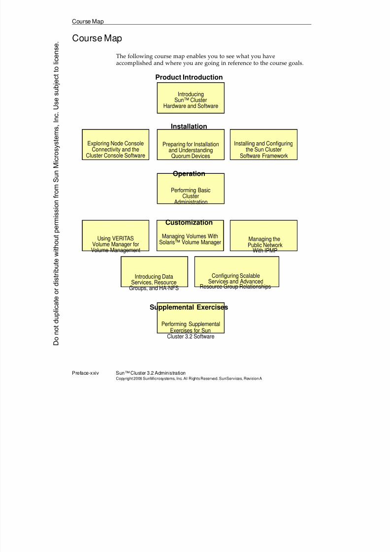
The following course map enables you to see what you haveaccomplished and where you are going in reference to the course goals.
Performing SupplementalExercises for Sun
Cluster 3.2 Software
Product Introduction
Supplemental Exercises
IntroducingSun™ Cluster
Hardware and Software
Customization
Using VERITAS
Volume Management
Managing Volumes With Managing the
Introducing Data Configuring ScalableServices and Advanced
Volume Manager for Solaris™ Volume ManagerPublic Network
With IPMP
Services, ResourceGroups, and HA-NFS
Operation
Performing BasicCluster
Administration
Installation
Exploring Node Console Preparing for Installation
and UnderstandingQuorum Devices
Installing and Configuring
Connectivity and theCluster Console Software
the Sun ClusterSoftware Framework
Resource Group Relationships
Donotduplicate
ordistributewithoutpermissionfrom SunMicrosystems,Inc.Usesubject
tolicense.
8/4/2019 Sun Cluster 3.2 Administration VC-ES-345
http://slidepdf.com/reader/full/sun-cluster-32-administration-vc-es-345 23/585
Topics Not Covered
About This Course Preface-xxvCopyright2006 SunMicrosystems, Inc. AllRightsReserved. SunServices,RevisionA
Topics Not Covered
This course does not cover the following topics. Many of the topics listedon the overhead are described in other courses offered by Sun Services:
q Solaris™ 10 Operating System (OS) Advanced Features orDifferences.
q Network administration.
q Solaris OS administration – Described in SA-239: Intermediate System Administration for the Solaris™ 9 Operating System and SA-299: Advanced System Administration for the Solaris™ 9 Operating System,and the Solaris 10 OS equivalents (SA-200-S10, SA-202-S10, and soon).
q Disk storage management – Described in ES-222: Solaris™ Volume
Manager Administration and ES-310: VERITAS ™ Volume Manager Administration.
Refer to the Sun Services catalog for specific information and registration.
8/4/2019 Sun Cluster 3.2 Administration VC-ES-345
http://slidepdf.com/reader/full/sun-cluster-32-administration-vc-es-345 24/585
How PreparedAreYou?
Preface-xxvi Sun™ Cluster 3.2 AdministrationCopyright2006 SunMicrosystems, Inc. AllRights Reserved.SunServices,RevisionA
How Prepared Are You?
To be sure you are prepared to take this course, can you answer yes to thefollowing questions?
q Can you explain virtual volume management terminology, such asmirroring, striping, concatenation, volumes, and mirrorsynchronization?
q Can you perform basic Solaris OS administration tasks, such as usingtar and ufsdump commands, creating user accounts, formatting diskdrives, using vi, installing the Solaris OS, installing patches, andadding packages?
q Do you have prior experience with Sun hardware and theOpenBoot™ programmable read-only memory (PROM) technology?
q
Are you familiar with general computer hardware, electrostaticprecautions, and safe handling practices?
Donotduplicate
ordistributewithoutpermissionfrom SunMicrosystems,Inc.Usesubject
tolicense.
8/4/2019 Sun Cluster 3.2 Administration VC-ES-345
http://slidepdf.com/reader/full/sun-cluster-32-administration-vc-es-345 25/585
Introductions
About This Course Preface-xxviiCopyright2006 SunMicrosystems, Inc. AllRightsReserved. SunServices,RevisionA
Introductions
Now that you have been introduced to the course, introduce yourself toeach other and the instructor, addressing the items shown in the following bullets.
q Name
q Company affiliation
q Title, function, and job responsibility
q Experience related to topics presented in this course
q Reasons for enrolling in this course
q Expectations for this course
8/4/2019 Sun Cluster 3.2 Administration VC-ES-345
http://slidepdf.com/reader/full/sun-cluster-32-administration-vc-es-345 26/585
How to Use Course Materials
Preface-xxviii Sun™ Cluster 3.2 AdministrationCopyright2006 SunMicrosystems, Inc. AllRights Reserved.SunServices,RevisionA
How to Use Course Materials
To enable you to succeed in this course, these course materials use alearning model that is composed of the following components:
q Goals – You should be able to accomplish the goals after finishingthis course and meeting all of its objectives.
q Objectives – You should be able to accomplish the objectives aftercompleting a portion of instructional content. Objectives supportgoals and can support other higher-level objectives.
q Lecture – The instructor will present information specific to theobjective of the module. This information should help you learn theknowledge and skills necessary to succeed with the activities.
q Activities – The activities take on various forms, such as an exercise,
self-check, discussion, and demonstration. Activities help to facilitatemastery of an objective.
q Visual aids – The instructor might use several visual aids to convey aconcept, such as a process, in a visual form. Visual aids commonlycontain graphics, animation, and video.
Donotduplicate
ordistributewithoutpermissionfrom SunMicrosystems,Inc.Usesubject
tolicense.
8/4/2019 Sun Cluster 3.2 Administration VC-ES-345
http://slidepdf.com/reader/full/sun-cluster-32-administration-vc-es-345 27/585
Conventions
About This Course Preface-xxixCopyright2006 SunMicrosystems, Inc. AllRightsReserved. SunServices,RevisionA
Conventions
The following conventions are used in this course to represent varioustraining elements and alternative learning resources.
Icons
Additional resources – Indicates other references that provide additionalinformation on the topics described in the module.
?
!
Discussion – Indicates a small-group or class discussion on the current
topic is recommended at this time.
Note – Indicates additional information that can help students but is notcrucial to their understanding of the concept being described. Studentsshould be able to understand the concept or complete the task withoutthis information. Examples of notational information include keywordshortcuts and minor system adjustments.
Caution – Indicates that there is a risk of personal injury from anonelectrical hazard, or risk of irreversible damage to data, software, orthe operating system. A caution indicates that the possibility of a hazard(as opposed to certainty) might happen, depending on the action of theuser.
8/4/2019 Sun Cluster 3.2 Administration VC-ES-345
http://slidepdf.com/reader/full/sun-cluster-32-administration-vc-es-345 28/585
Conventions
Preface-xxx Sun™ Cluster 3.2 AdministrationCopyright2006 SunMicrosystems, Inc. AllRights Reserved.SunServices,RevisionA
Typographical Conventions
Courier is used for the names of commands, files, directories,programming code, and on-screen computer output; for example:
Use ls -al to list all files.system% You have mail.
Courier is also used to indicate programming constructs, such as classnames, methods, and keywords; for example:
Use the getServletInfomethod to get author information.The java.awt.Dialog class contains Dialog constructor.
Courier bold is used for characters and numbers that you type; forexample:
To list the files in this directory, type:# ls
Courier bold is also used for each line of programming code that isreferenced in a textual description; for example:
1 import java.io.*;
2 import javax.servlet.*;
3 import javax.servlet.http.*;
Notice the javax.servlet interface is imported to allow access to itslife cycle methods (Line 2).
Courier italic is used for variables and command-line placeholdersthat are replaced with a real name or value; for example:
To delete a file, use the rm filename command.
Courier italic bold is used to represent variables whose values are to be entered by the student as part of an activity; for example:
Type chmod a+rwx filename to grant read, write, and executerights for filename to world, group, and users.
Palatino italic is used for book titles, new words or terms, or words thatyou want to emphasize; for example:
Read Chapter 6 in the User’s Guide.These are called class options.
Donotduplicate
ordistributewithoutpermissionfrom SunMicrosystems,Inc.Usesubject
tolicense.
8/4/2019 Sun Cluster 3.2 Administration VC-ES-345
http://slidepdf.com/reader/full/sun-cluster-32-administration-vc-es-345 29/585
8/4/2019 Sun Cluster 3.2 Administration VC-ES-345
http://slidepdf.com/reader/full/sun-cluster-32-administration-vc-es-345 30/585
Relevance
1-2 Sun™Cluster 3 .2AdministrationCopyright2006 SunMicrosystems, Inc. AllRights Reserved.SunServices,RevisionA
Relevance
?
!
Discussion – The following questions are relevant to understanding thecontent of this module:
q Are there similarities between the redundant hardware componentsin a standalone server and the redundant hardware components in acluster?
q Why is it impossible to achieve industry standards of highavailability on a standalone server?
q Why are a variety of applications that run in the Sun Clustersoftware environment said to be cluster-unaware?
q How do cluster-unaware applications differ from cluster-awareapplications?
q What services does the Sun Cluster software framework provide forall the applications running in the cluster?
q Do global devices and global file systems have uses other than forscalable applications in the cluster?
Donotduplicate
ordistributewithoutpermissionfrom SunMicrosystems,Inc.Usesubject
tolicense.
8/4/2019 Sun Cluster 3.2 Administration VC-ES-345
http://slidepdf.com/reader/full/sun-cluster-32-administration-vc-es-345 31/585
Additional Resources
Introducing Sun™ Cluster Hardware and Software 1-3Copyright2006 SunMicrosystems, Inc. AllRightsReserved. SunServices,RevisionA
Additional Resources
Additional resources – The following references provide additional
information on the topics described in this module:q Sun Cluster System Administration Guide for Solaris OS, part number
819-2971.
q Sun Cluster Software Installation Guide for Solaris OS, part number 819-2970.
q Sun Cluster Concepts Guide for Solaris OS, part number 819-2969.
8/4/2019 Sun Cluster 3.2 Administration VC-ES-345
http://slidepdf.com/reader/full/sun-cluster-32-administration-vc-es-345 32/585
Defining Clustering
1-4 Sun™Cluster 3 .2AdministrationCopyright2006 SunMicrosystems, Inc. AllRights Reserved.SunServices,RevisionA
Defining Clustering
Clustering is a general term that describes a group of two or more separateservers operating as a harmonious unit. Clusters generally have thefollowing characteristics:
q Separate server nodes, each booting from its own, non-shared, copy ofthe OS
q Dedicated hardware interconnect, providing a private transport only between the nodes of the same cluster
q Multiported storage, providing paths from at least two nodes in thecluster to each physical storage device that stores data for theapplications running in the cluster
q Cluster software framework, providing cluster-specific knowledge tothe nodes in the cluster about the health of the hardware and thehealth and state of their peer nodes
q General goal of providing a platform for HA and scalability for theapplications running in the cluster
q Support for a variety of cluster-unaware applications and cluster-awareapplications
High-Availability (HA) Platforms
Clusters are generally marketed as the only way to provide high-availability (HA) for the applications that run on them.
HA can be defined as a minimization of downtime rather than thecomplete elimination of downtime. Many standalone servers themselvesare marketed as providing higher levels of availability than our competitors (or predecessors). Most true standards of HA cannot be achieved in astandalone server environment.
HA Standards
HA standards are usually phrased with wording such as “provides5 nines availability.” This means 99.999 percent uptime for the applicationor about five minutes of downtime per year. One clean server reboot oftenalready exceeds that amount of downtime.
Donotduplicate
ordistributewithoutpermissionfrom SunMicrosystems,Inc.Usesubject
tolicense.
8/4/2019 Sun Cluster 3.2 Administration VC-ES-345
http://slidepdf.com/reader/full/sun-cluster-32-administration-vc-es-345 33/585
Defining Clustering
Introducing Sun™ Cluster Hardware and Software 1-5Copyright2006 SunMicrosystems, Inc. AllRightsReserved. SunServices,RevisionA
How Clusters Provide HA (Inter-Node Failover)
Clusters provide an environment where, in the case of any singlehardware or software failure in the cluster, application services and dataare recovered automatically (without human intervention) and quickly
(faster than a server reboot). The existence of the redundant servers in thecluster and redundant server-storage paths makes this possible.
HA Benefits for Unplanned and Planned Outages
The HA benefit that cluster environments provide involves not onlyhardware and software failures, but also planned outages. While a clustercan automatically relocate applications inside the cluster in the case offailures, it can also manually relocate services for planned outages. Assuch, normal reboots for hardware maintenance in the cluster only affectsthe uptime of the applications for as much time as it takes to manuallyrelocate the applications to different servers in the cluster.
Fault-Tolerant Servers AreNot an Alternative to HA Clusters
Many vendors provide servers that are marketed as fault-tolerant. Theseservers are designed to be able to tolerate any single hardware failure, forexample memory failure, central processing unit (CPU) failure, and so on,without any downtime.
There is a common misconception that fault-tolerant servers are an
alternative to HA clusters, or that a fault-tolerant server supersedes HA insome way. In fact, while fault-tolerant servers can hide any hardwarefailure, they are not designed to provide especially fast recovery in thecase of a software failure, such as a Solaris OS kernel panic or anapplication failure. Recovery in these circumstances on a singlefault-tolerant server might still require a full OS reboot which, aspreviously stated, might already exceed maximum downtime permitted by the HA standards to which you aspire.
Platforms for Scalable Applications
Clusters also provide an integrated hardware and software environmentfor scalable applications. Scalability is defined as the ability to increaseapplication performance by supporting multiple instances of applicationson different nodes in the cluster. These instances are generally accessingthe same data as each other.
8/4/2019 Sun Cluster 3.2 Administration VC-ES-345
http://slidepdf.com/reader/full/sun-cluster-32-administration-vc-es-345 34/585
Sun Cluster 3.2 Hardware andSoftware Environment
1-6 Sun™Cluster 3 .2AdministrationCopyright2006 SunMicrosystems, Inc. AllRights Reserved.SunServices,RevisionA
Clusters generally do not require a choice between availability andperformance. HA is generally built-in to scalable applications as well asnon-scalable ones. In scalable applications, you might not need to relocatefailed applications because other instances are already running on othernodes. You might still need to perform recovery on behalf of failed
instances.
Sun Cluster 3.2 Hardware and Software Environment
The Sun Cluster 3.2 hardware and software environment is Sun’s latestgeneration clustering product. The following features distinguish the SunCluster product from competitors in the field:
q Support for two to 16 nodes – Nodes can be added, removed, andreplaced from the cluster without any interruption of application
service.
q Global device implementation – While data storage must be physicallyconnected on paths from at least two different nodes in the SunCluster 3.2 hardware and software environment, all the storage inthe cluster is logically available from every node in the cluster usingstandard device semantics.
This provides the flexibility to run applications on nodes that usedata that are not even physically connected to the nodes. Moreinformation about global device file naming and location can befound in ‘‘Global Storage Services’’ on page 1-35.
q Global file system implementation – The Sun Cluster softwareframework provides a global file service independent of anyparticular application running in the cluster, so that the same filescan be accessed on every node of the cluster, regardless of thestorage topology.
q Cluster framework services implemented in the kernel – The Sun Clustersoftware is tightly integrated with the Solaris 9 OS and Solaris 10 OSkernels. Node monitoring capability, transport monitoring capability,and the global device and file system implementation are
implemented in the kernel to provide higher reliability andperformance.
q Off-the-shelf application support – The Sun Cluster product includesdata service agents for a large variety of cluster-unawareapplications. These are tested programs and fault monitors that
Donotduplicate
ordistributewithoutpermissionfrom SunMicrosystems,Inc.Usesubject
tolicense.
8/4/2019 Sun Cluster 3.2 Administration VC-ES-345
http://slidepdf.com/reader/full/sun-cluster-32-administration-vc-es-345 35/585
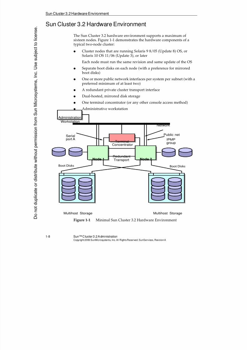
8/4/2019 Sun Cluster 3.2 Administration VC-ES-345
http://slidepdf.com/reader/full/sun-cluster-32-administration-vc-es-345 36/585
Sun Cluster 3.2 Hardware Environment
1-8 Sun™Cluster 3 .2AdministrationCopyright2006 SunMicrosystems, Inc. AllRights Reserved.SunServices,RevisionA
Sun Cluster 3.2 Hardware Environment
The Sun Cluster 3.2 hardware environment supports a maximum ofsixteen nodes. Figure 1-1 demonstrates the hardware components of atypical two-node cluster:
q Cluster nodes that are running Solaris 9 8/05 (Update 8) OS, orSolaris 10 OS 11/06 (Update 3), or later
Each node must run the same revision and same update of the OS
q Separate boot disks on each node (with a preference for mirrored boot disks)
q One or more public network interfaces per system per subnet (with apreferred minimum of at least two)
q A redundant private cluster transport interface
q Dual-hosted, mirrored disk storage
q One terminal concentrator (or any other console access method)
q Administrative workstation
Figure 1-1 Minimal Sun Cluster 3.2 Hardware Environment
Network
Node 1 Node 2
IPMPgroup
Serialport A
Multihost StorageMultihost Storage
Public net
Administration
Workstation
TerminalConcentrator
RedundantTransport
Boot DisksBoot Disks
Donotduplicate
ordistributewithoutpermissionfrom SunMicrosystems,Inc.Usesubject
tolicense.
8/4/2019 Sun Cluster 3.2 Administration VC-ES-345
http://slidepdf.com/reader/full/sun-cluster-32-administration-vc-es-345 37/585
Sun Cluster 3.2 Hardware Environment
Introducing Sun™ Cluster Hardware and Software 1-9Copyright2006 SunMicrosystems, Inc. AllRightsReserved. SunServices,RevisionA
Cluster Host Systems
A wide range of Sun server platforms are supported for use in theclustered environment. These range from small rackmounted servers(SPARC® and x86 servers) up to Sun’s largest enterprise-level servers,
including Sun Fire™ 25K and 15K servers.
Heterogeneous environments are supported (that is, different types ofservers used as nodes in the same cluster), based on the network andstorage host adapters used, not on the servers themselves.
You cannot mix SPARC and x86 servers in the same cluster.
Cluster Transport Interface
All nodes in a cluster are linked by a private cluster transport. Thetransport is redundant and can be used for the following purposes:
q Cluster-wide monitoring and recovery
q Global data access (transparent to applications)
q Application-specific transport for cluster-aware applications (such asOracle RAC)
Clusters must be defined with a minimum of two separate private networks
that form the cluster transport. You can have more than two privatenetworks (and you can add more later). These private networks canprovide a performance benefit in certain circumstances because globaldata access traffic is striped across all of the transports.
Crossover cables are often used in a two-node cluster. Switches areoptional when you have two nodes and are required for more than twonodes.
The following types of cluster transport hardware are supported:
q
Fast Ethernetq Gigabit Ethernet
q Scalable coherent interface (SCI) intended for remote shared memory(RSM) applications. The SCI interconnect is supported only inclusters with a maximum of four nodes.
8/4/2019 Sun Cluster 3.2 Administration VC-ES-345
http://slidepdf.com/reader/full/sun-cluster-32-administration-vc-es-345 38/585
Sun Cluster 3.2 Hardware Environment
1-10 Sun™ Cluster 3.2 AdministrationCopyright2006 SunMicrosystems, Inc. AllRights Reserved.SunServices,RevisionA
q Infiniband (Solaris 10 OS only)
This is a relatively new industry standard interconnect used outsideof the Sun Cluster environment for interconnecting a variety of hostsand storage devices. In the Sun Cluster environment it is supportedonly as an interconnect between hosts, not between hosts and
storage devices.
Public Network Interfaces
Each node must have public network interfaces under control of theSolaris OS IP Multipathing (IPMP) software. It is recommended to have atleast two interfaces in each IPMP group. You may configure as manyIPMP groups as required.
A Sun Cluster server is not allowed to act as a router.
Not all available network interface cards (NICs) are supported in the SunCluster 3.2 hardware environment.
Donotduplicate
ordistributewithoutpermissionfrom SunMicrosystems,Inc.Usesubject
tolicense.
8/4/2019 Sun Cluster 3.2 Administration VC-ES-345
http://slidepdf.com/reader/full/sun-cluster-32-administration-vc-es-345 39/585
8/4/2019 Sun Cluster 3.2 Administration VC-ES-345
http://slidepdf.com/reader/full/sun-cluster-32-administration-vc-es-345 40/585
Sun Cluster 3.2 Hardware Environment
1-12 Sun™ Cluster 3.2 AdministrationCopyright2006 SunMicrosystems, Inc. AllRights Reserved.SunServices,RevisionA
Terminal Concentrator (or Other Console Access)
Servers supported in the Sun Cluster environment have a variety ofconsole access mechanisms.
If you are using a serial port console access mechanism (ttya), then youmight likely have a terminal concentrator in order to provide theconvenience of remote access to your node consoles.A terminalconcentrator (TC) is a device that provides data translation from thenetwork to serial port interfaces. Each of the serial port outputs connectsto a separate node in the cluster through serial port A.
There is always a trade-off between convenience and security. You mightprefer to have only dumb-terminal console access to the cluster nodes, andkeep these terminals behind locked doors requiring stringent securitychecks to open them. This is acceptable (although less convenient toadminister) for Sun Cluster 3.2 hardware as well.
Administrative Workstation
Included with the Sun Cluster software is the administration consolesoftware, which can be installed on any SPARC or x86 Solaris OSworkstation. The software can be a convenience in managing the multiple
nodes of the cluster from a centralized location. It does not affect thecluster in any other way.
Donotduplicate
ordistributewithoutpermissionfrom SunMicrosystems,Inc.Usesubject
tolicense.
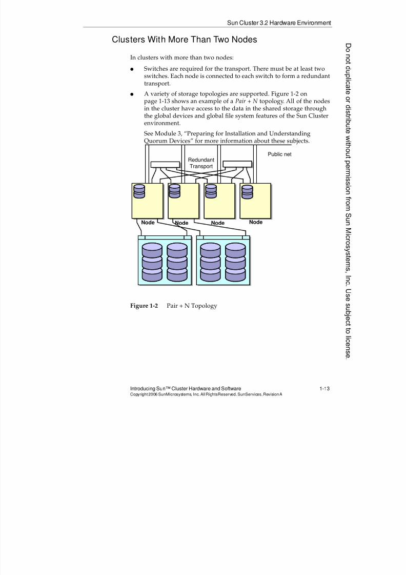
8/4/2019 Sun Cluster 3.2 Administration VC-ES-345
http://slidepdf.com/reader/full/sun-cluster-32-administration-vc-es-345 41/585
Sun Cluster 3.2 Hardware Environment
Introducing Sun™ Cluster Hardware and Software 1-13Copyright2006 SunMicrosystems, Inc. AllRightsReserved. SunServices,RevisionA
Clusters With More Than Two Nodes
In clusters with more than two nodes:
q Switches are required for the transport. There must be at least two
switches. Each node is connected to each switch to form a redundanttransport.
q A variety of storage topologies are supported. Figure 1-2 onpage 1-13 shows an example of a Pair + N topology. All of the nodesin the cluster have access to the data in the shared storage throughthe global devices and global file system features of the Sun Clusterenvironment.
See Module 3, “Preparing for Installation and UnderstandingQuorum Devices” for more information about these subjects.
Figure 1-2 Pair + N Topology
Node Node
RedundantTransport
Public net
NodeNode
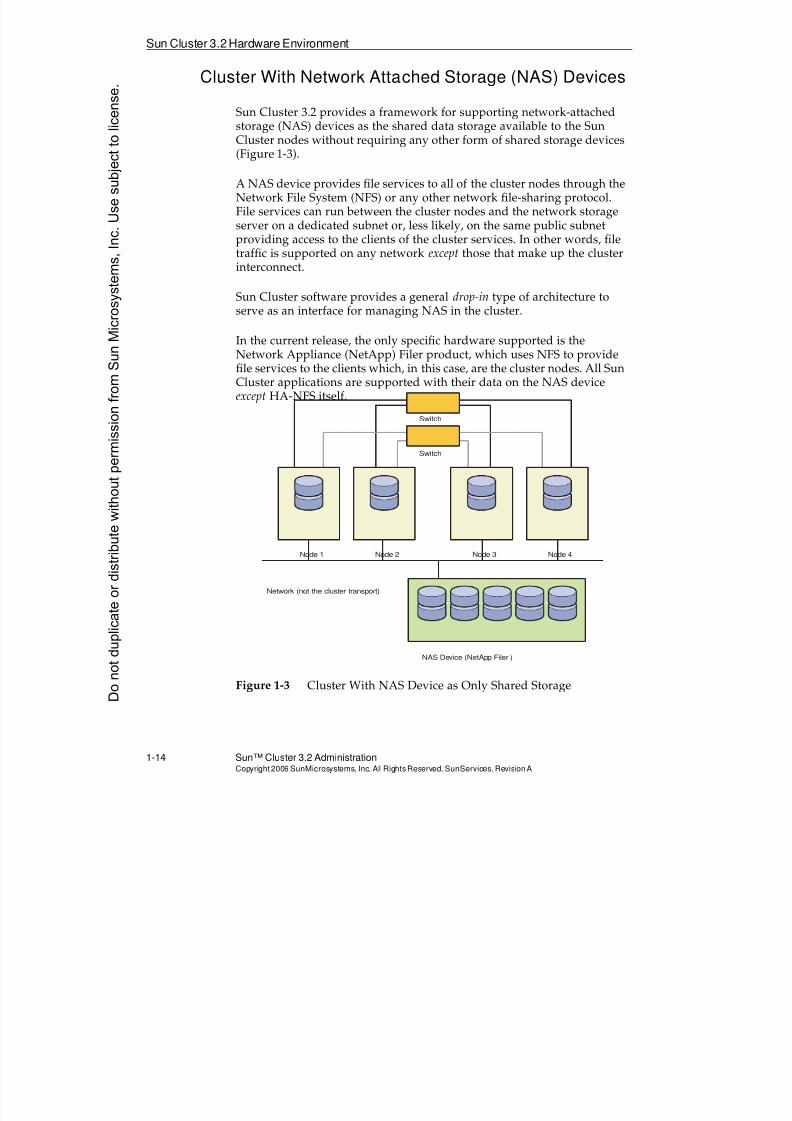
8/4/2019 Sun Cluster 3.2 Administration VC-ES-345
http://slidepdf.com/reader/full/sun-cluster-32-administration-vc-es-345 42/585
Sun Cluster 3.2 Hardware Environment
1-14 Sun™ Cluster 3.2 AdministrationCopyright2006 SunMicrosystems, Inc. AllRights Reserved.SunServices,RevisionA
Cluster With Network Attached Storage (NAS) Devices
Sun Cluster 3.2 provides a framework for supporting network-attachedstorage (NAS) devices as the shared data storage available to the SunCluster nodes without requiring any other form of shared storage devices
(Figure 1-3).
A NAS device provides file services to all of the cluster nodes through theNetwork File System (NFS) or any other network file-sharing protocol.File services can run between the cluster nodes and the network storageserver on a dedicated subnet or, less likely, on the same public subnetproviding access to the clients of the cluster services. In other words, filetraffic is supported on any network except those that make up the clusterinterconnect.
Sun Cluster software provides a general drop-in type of architecture toserve as an interface for managing NAS in the cluster.
In the current release, the only specific hardware supported is theNetwork Appliance (NetApp) Filer product, which uses NFS to providefile services to the clients which, in this case, are the cluster nodes. All SunCluster applications are supported with their data on the NAS deviceexcept HA-NFS itself.
Figure 1-3 Cluster With NAS Device as Only Shared Storage
Network (not the cluster transport)
Node 1 Node 2 Node 3 Node 4
Switch
Switch
NAS Device (NetApp Filer )
Donotduplicate
ordistributewithoutpermissionfrom SunMicrosystems,Inc.Usesubject
tolicense.
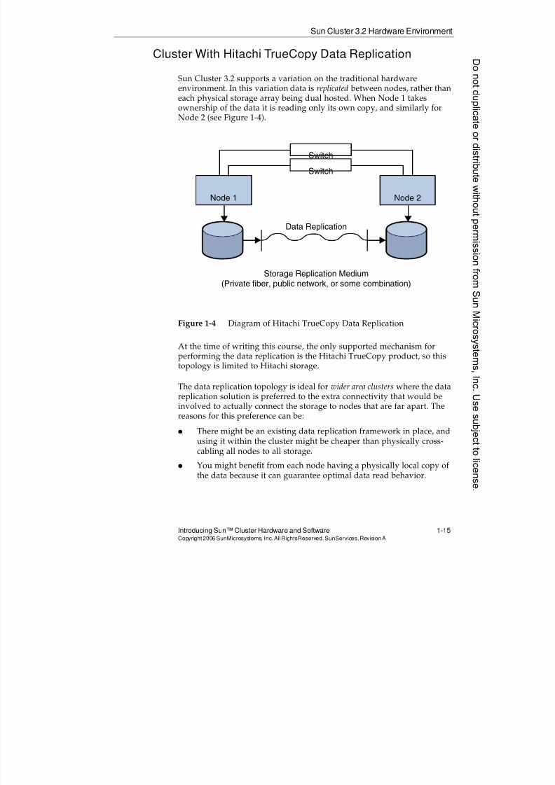
8/4/2019 Sun Cluster 3.2 Administration VC-ES-345
http://slidepdf.com/reader/full/sun-cluster-32-administration-vc-es-345 43/585

8/4/2019 Sun Cluster 3.2 Administration VC-ES-345
http://slidepdf.com/reader/full/sun-cluster-32-administration-vc-es-345 44/585
Sun Cluster 3.2 Hardware Environment
1-16 Sun™ Cluster 3.2 AdministrationCopyright2006 SunMicrosystems, Inc. AllRights Reserved.SunServices,RevisionA
NOTES:
Donotduplicate
ordistributewithoutpermissionfrom SunMicrosystems,Inc.Usesubject
tolicense.
8/4/2019 Sun Cluster 3.2 Administration VC-ES-345
http://slidepdf.com/reader/full/sun-cluster-32-administration-vc-es-345 45/585
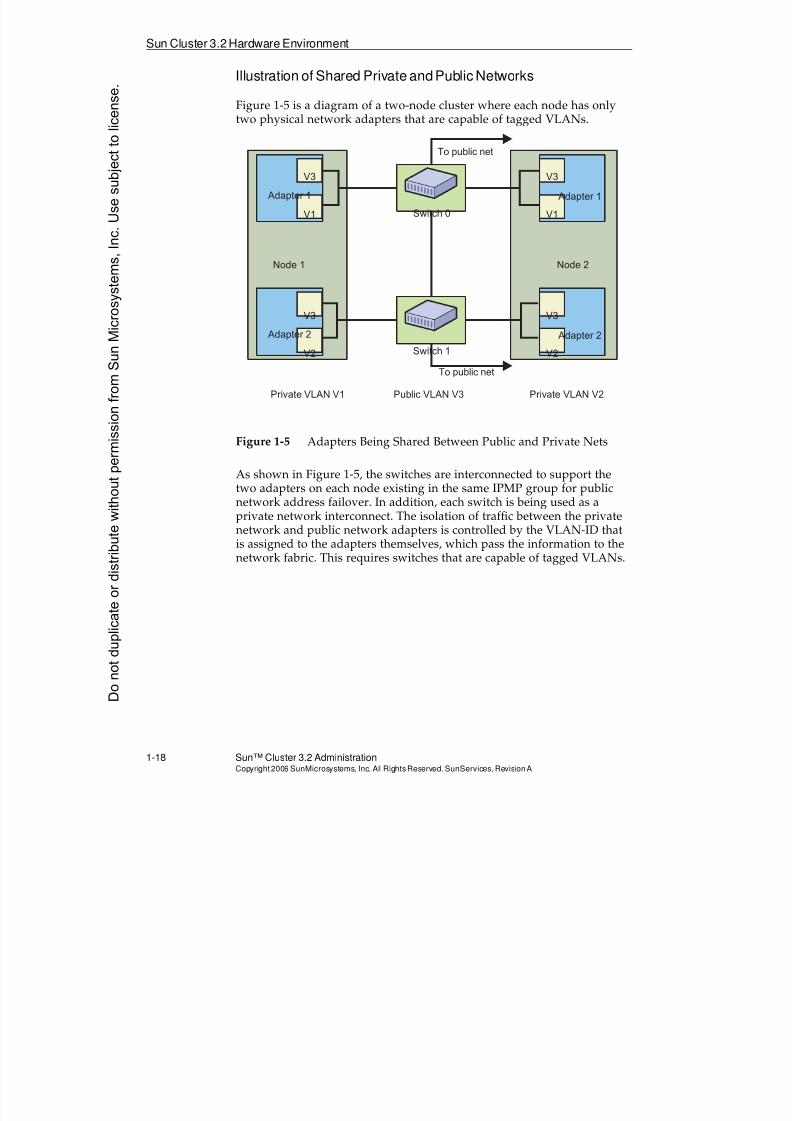
8/4/2019 Sun Cluster 3.2 Administration VC-ES-345
http://slidepdf.com/reader/full/sun-cluster-32-administration-vc-es-345 46/585
8/4/2019 Sun Cluster 3.2 Administration VC-ES-345
http://slidepdf.com/reader/full/sun-cluster-32-administration-vc-es-345 47/585
Sun Cluster 3.2 Hardware Environment
Introducing Sun™ Cluster Hardware and Software 1-19Copyright2006 SunMicrosystems, Inc. AllRightsReserved. SunServices,RevisionA
Sun Cluster Hardware Redundancy Features
The following items summarize the generally required and optionalhardware redundancy features in the Sun Cluster hardware environment:
q Redundant server nodes are required.q Redundant transport is required.
q HA access to and from each node to data storage is required. That is,at least one of the following is required.
q Mirroring across controllers for Just a Bunch Of Disks (JBOD) orfor hardware RAID devices without multipathing (such assingle-brick 6120’s, or 3310 RAID boxes each with only a singleRAID controller)
q Multipathing from each connected node to HA hardware RAID
devicesq Redundant public network interfaces per subnet are recommended.
q Mirrored boot disks are recommended.
You should locate redundant components as far apart as possible. Forexample, on a system with multiple input/output (I/O) boards, youshould put the redundant transport interfaces, the redundant public nets,and the redundant storage array controllers on two different I/O boards.
Cluster in a Box
The Sun Cluster 3.2 hardware environment supports clusters with both(or all) nodes in the same physical frame for the following domain-basedservers (current at the time of writing this course):
q Sun Fire 25K/20K/15K/12K servers (high-end servers)
q Sun Fire 3800 through 6800 and 4900/6900 servers (midrangeservers)
q Sun Enterprise™ 10000 servers
You should take as many redundancy precautions as possible, forexample, running multiple domains in different segments onSun Fire 3x00 through 6x00 servers and segmenting across the powerplane on Sun Fire 6x00 servers.
8/4/2019 Sun Cluster 3.2 Administration VC-ES-345
http://slidepdf.com/reader/full/sun-cluster-32-administration-vc-es-345 48/585
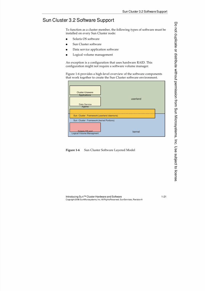
8/4/2019 Sun Cluster 3.2 Administration VC-ES-345
http://slidepdf.com/reader/full/sun-cluster-32-administration-vc-es-345 49/585
Sun Cluster 3.2 SoftwareSupport
Introducing Sun™ Cluster Hardware and Software 1-21Copyright2006 SunMicrosystems, Inc. AllRightsReserved. SunServices,RevisionA
Sun Cluster 3.2 Software Support
To function as a cluster member, the following types of software must beinstalled on every Sun Cluster node:
q Solaris OS softwareq Sun Cluster software
q Data service application software
q Logical volume management
An exception is a configuration that uses hardware RAID. Thisconfiguration might not require a software volume manager.
Figure 1-6 provides a high-level overview of the software components
that work together to create the Sun Cluster software environment.
Figure 1-6 Sun Cluster Software Layered Model
Cluster-Unaware
Applications
Data Service Agents
Sun Cluster Framework (userland daemons)
Sun Cluster Framework (kernel Portions)
Solaris OS andLogical Volume Managment
userland
kernel
8/4/2019 Sun Cluster 3.2 Administration VC-ES-345
http://slidepdf.com/reader/full/sun-cluster-32-administration-vc-es-345 50/585
8/4/2019 Sun Cluster 3.2 Administration VC-ES-345
http://slidepdf.com/reader/full/sun-cluster-32-administration-vc-es-345 51/585
8/4/2019 Sun Cluster 3.2 Administration VC-ES-345
http://slidepdf.com/reader/full/sun-cluster-32-administration-vc-es-345 52/585
Sun Cluster 3.2 Software Support
1-24 Sun™ Cluster 3.2 AdministrationCopyright2006 SunMicrosystems, Inc. AllRights Reserved.SunServices,RevisionA
Solaris 10 OS Service Management Facility (SMF)
The Solaris 10 Service Management Facility provides a new way ofmanaging OS services. SMF replaces (more or less) both the entire/etc/rc?.d boot script scheme and the entire inetd framework. Instead,
SMF provides a single unified framework for launching and restartingdaemons, network services, and in fact anything that might be considereda service.
The main advantages of SMF are that:
q It provides a framework for specifying dependencies and orderingamong services.
q It provides a framework for restarting services, while takingdependencies into account.
q It can speed up the boot process significantly because SMF canautomatically graph the dependencies and launch the appropriatenon-dependent services in parallel.
Sun Cluster 3.2 Integration With SMF
Sun Cluster 3.2 software integrates with the Solaris 10 SMF in thefollowing ways:
q Sun Cluster 3.2 framework daemons are defined as SMF services.
The fact that cluster daemons are defined as SMF services in the
Solaris 10 OS makes very little difference in how you manage thecluster. You should never start or stop Sun Cluster frameworkdaemons by hand.
q Sun Cluster 3.2 can integrate applications designed as SMF servicesinto the cluster as clustered services.
Sun Cluster has SMF-specific proxy agents that turn SMF-basedapplications, defined outside of the cluster using SMF, into clusteredapplications, while retaining all of the logic and dependenciesimplied by the SMF definition.
Donotduplicate
ordistributewithoutpermissionfrom SunMicrosystems,Inc.Usesubject
tolicense.
8/4/2019 Sun Cluster 3.2 Administration VC-ES-345
http://slidepdf.com/reader/full/sun-cluster-32-administration-vc-es-345 53/585
Types of Applications in the Sun Cluster SoftwareEnvironment
Introducing Sun™ Cluster Hardware and Software 1-25Copyright2006 SunMicrosystems, Inc. AllRightsReserved. SunServices,RevisionA
Types of Applications in the Sun Cluster SoftwareEnvironment
The Sun Cluster software environment supports both cluster-unaware and
cluster-aware applications.
Cluster-Unaware (Off-the-Shelf) Applications
A cluster-unaware application is an application that typically runs on asingle server.
The majority of applications that run in a cluster are in the cluster-unaware category and are part of the main focus of this course.
Two main categories of cluster-unaware applications can run in the SunCluster 3.2 environment. These are described on the following pages ofthis module and also in detail in Module 9, “Introducing Data Services,Resource Groups, and HA-NFS”, and Module 10, “Configuring ScalableServices and Advanced Resource Group Relationships”. The applicationsinclude the following:
q Failover applications
q Scalable applications
The common elements of all of these applications are the following:q The cluster’s resource group manager (RGM) coordinates all stopping
and starting of the applications, which are never started and stopped by traditional Solaris OS boot methods.
q A data service agent for the application provides the “glue” to make itwork properly in the Sun Cluster software environment. Thisincludes methods to start and stop the application appropriately inthe cluster, as well as fault monitors specific to that application.
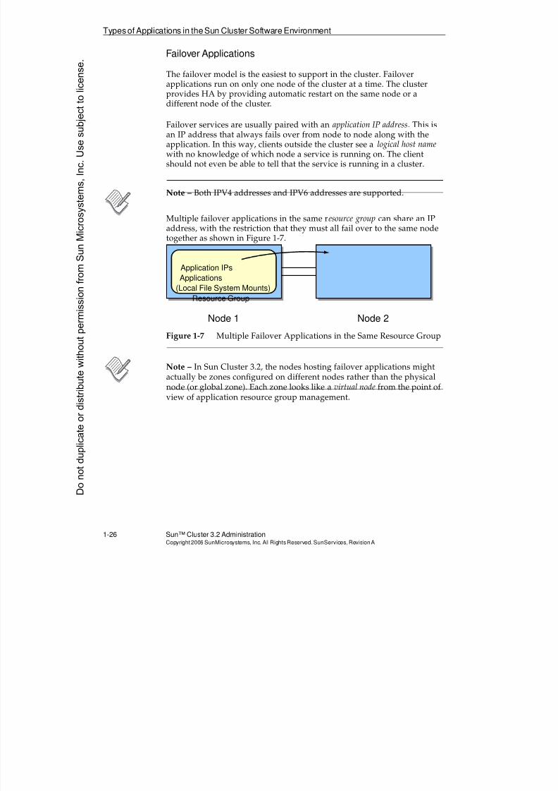
8/4/2019 Sun Cluster 3.2 Administration VC-ES-345
http://slidepdf.com/reader/full/sun-cluster-32-administration-vc-es-345 54/585
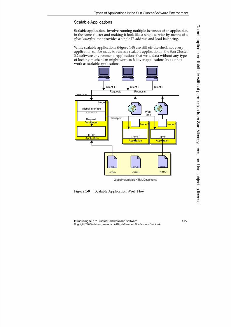
8/4/2019 Sun Cluster 3.2 Administration VC-ES-345
http://slidepdf.com/reader/full/sun-cluster-32-administration-vc-es-345 55/585
Types of Applications in the Sun Cluster SoftwareEnvironment
Introducing Sun™ Cluster Hardware and Software 1-27Copyright2006 SunMicrosystems, Inc. AllRightsReserved. SunServices,RevisionA
Scalable Applications
Scalable applications involve running multiple instances of an applicationin the same cluster and making it look like a single service by means of a global interface that provides a single IP address and load balancing.
While scalable applications (Figure 1-8) are still off-the-shelf, not everyapplication can be made to run as a scalable application in the Sun Cluster3.2 software environment. Applications that write data without any typeof locking mechanism might work as failover applications but do notwork as scalable applications.
Figure 1-8 Scalable Application Work Flow
<HTML>
</HTML>
<HTML>
</HTML>
<HTML>
</HTML>
Node 1
Node 2 Node 3
Globally Available HTML Documents
HTTPApplication HTTP
Application
HTTPApplication
Global Interfacexyz.com
RequestDistribution
Transport
WebPage
Client 1 Client 2 Client 3Requests Requests
Network
8/4/2019 Sun Cluster 3.2 Administration VC-ES-345
http://slidepdf.com/reader/full/sun-cluster-32-administration-vc-es-345 56/585
Typesof Applications in theSun Cluster Software Environment
1-28 Sun™ Cluster 3.2 AdministrationCopyright2006 SunMicrosystems, Inc. AllRights Reserved.SunServices,RevisionA
Cluster-Aware Applications
Cluster-aware applications are applications where knowledge of the clusteris built-in to the software. They differ from cluster-unaware applications inthe following ways:
q Multiple instances of the application running on different nodes areaware of each other and communicate across the private transport.
q It is not required that the Sun Cluster software framework RGM startand stop these applications. Because these applications arecluster-aware, they can be started in their own independent scripts,or by hand.
q Applications are not necessarily logically grouped with externalapplication IP addresses. If they are, the network connections can bemonitored by cluster commands. It is also possible to monitor these
cluster-aware applications with Sun Cluster 3.2 software frameworkresource types.
Parallel Database Applications
Parallel databases are a special type of cluster application. Multipleinstances of the database server cooperate in the cluster, handlingdifferent queries on the same database and even providing parallel querycapability on large queries. The following are supported in the SunCluster 3.2 software environment:
q Oracle 9i Real Application Clusters (RAC)
q Oracle 10g RAC
Donotduplicate
ordistributewithoutpermissionfrom SunMicrosystems,Inc.Usesubject
tolicense.
8/4/2019 Sun Cluster 3.2 Administration VC-ES-345
http://slidepdf.com/reader/full/sun-cluster-32-administration-vc-es-345 57/585
8/4/2019 Sun Cluster 3.2 Administration VC-ES-345
http://slidepdf.com/reader/full/sun-cluster-32-administration-vc-es-345 58/585
Sun Cluster 3.2 Software Data Service Support
1-30 Sun™ Cluster 3.2 AdministrationCopyright2006 SunMicrosystems, Inc. AllRights Reserved.SunServices,RevisionA
Sun Cluster 3.2 Software Data Service Support
This section contains a list of Sun-supported data service agents that makecluster-unaware applications HA, either in failover or scalableconfigurations.
HA and Scalable Data Service Support
The Sun Cluster software provides preconfigured components thatsupport the following HA data services. These are the componentsavailable at the time of the writing this course:
q Sun Cluster HA for Oracle Server (failover)
q Sun Cluster HA for Oracle E-Business Suite (failover)
q Sun Cluster HA for Oracle 9i Application Server (failover)
q Sun Cluster HA for Sun Java System Web Server (failover orscalable)
q Sun Cluster HA for Sun Java System Application Server (failover)
q Sun Cluster HA for Sun Java System Application Server EE HADB(failover)
q Sun Cluster HA for Sun Java System Directory Server (failover)
q Sun Cluster HA for Sun Java System Messaging Server (failover)
q Sun Cluster HA for Sun Java System Calendar Server (failover)
q Sun Cluster HA for Sun Instant Messaging (failover)
q Sun Cluster HA for Sun Java System Message Queue software(failover)
q Sun Cluster HA for Apache Web Server (failover or scalable)
q Sun Cluster HA for Apache Tomcat (failover or scalable)
q Sun Cluster HA for Domain Name Service (DNS) (failover)
q Sun Cluster HA for Network File System (NFS) (failover)
q Sun Cluster HA for Dynamic Host Configuration Protocol (DHCP)(failover)
q Sun Cluster HA for SAP (failover or scalable)
q Sun Cluster HA for SAP LiveCache (failover)
q Sun Cluster HA for SAP Web Application Server (failover orscalable)D
onotduplicate
ordistributewithoutpermissionfrom SunMicrosystems,Inc.Usesubject
tolicense.
8/4/2019 Sun Cluster 3.2 Administration VC-ES-345
http://slidepdf.com/reader/full/sun-cluster-32-administration-vc-es-345 59/585
8/4/2019 Sun Cluster 3.2 Administration VC-ES-345
http://slidepdf.com/reader/full/sun-cluster-32-administration-vc-es-345 60/585
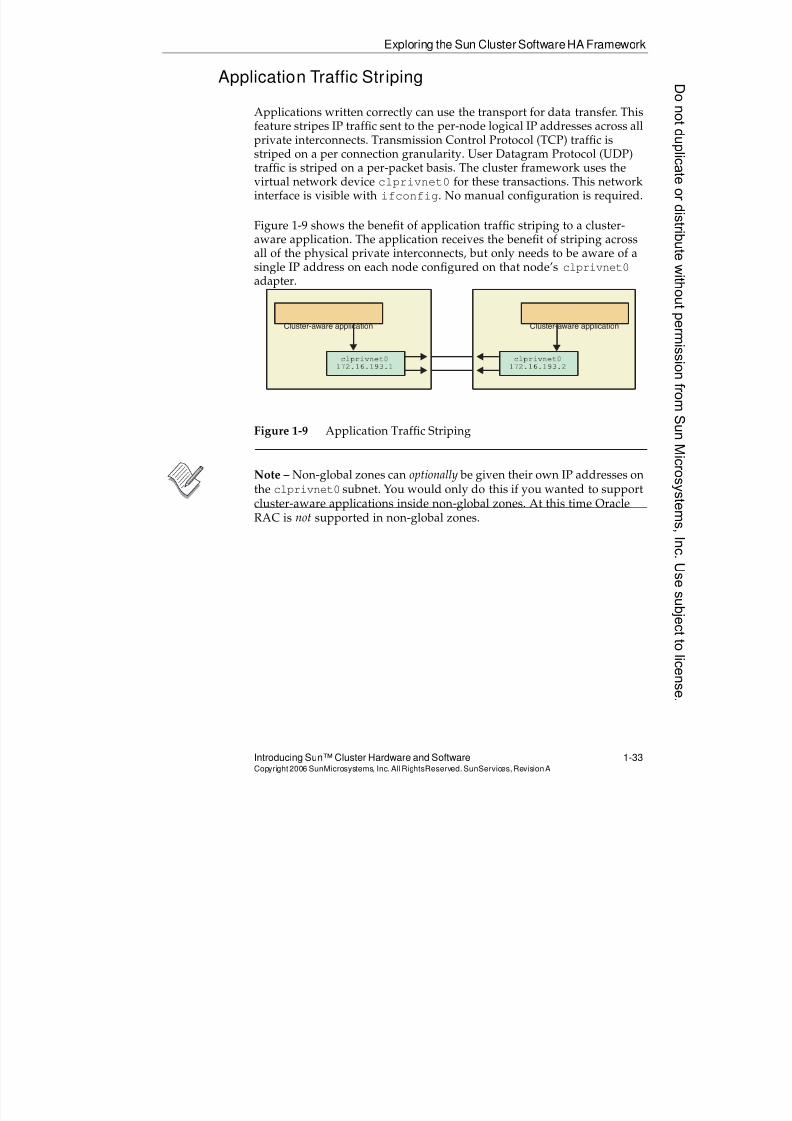
8/4/2019 Sun Cluster 3.2 Administration VC-ES-345
http://slidepdf.com/reader/full/sun-cluster-32-administration-vc-es-345 61/585
Exploring the Sun Cluster SoftwareHA Framework
Introducing Sun™ Cluster Hardware and Software 1-33Copyright2006 SunMicrosystems, Inc. AllRightsReserved. SunServices,RevisionA
Application Traffic Striping
Applications written correctly can use the transport for data transfer. Thisfeature stripes IP traffic sent to the per-node logical IP addresses across allprivate interconnects. Transmission Control Protocol (TCP) traffic is
striped on a per connection granularity. User Datagram Protocol (UDP)traffic is striped on a per-packet basis. The cluster framework uses thevirtual network device clprivnet0 for these transactions. This networkinterface is visible with ifconfig. No manual configuration is required.
Figure 1-9 shows the benefit of application traffic striping to a cluster-aware application. The application receives the benefit of striping acrossall of the physical private interconnects, but only needs to be aware of asingle IP address on each node configured on that node’s clprivnet0adapter.
Figure 1-9 Application Traffic Striping
Note – Non-global zones can optionally be given their own IP addresses onthe clprivnet0 subnet. You would only do this if you wanted to supportcluster-aware applications inside non-global zones. At this time OracleRAC is not supported in non-global zones.
Cluster-aware application Cluster-aware application
c l p r i v n e t 0
1 7 2 . 1 6 . 1 9 3 . 2
c l p r i v n e t 0
1 7 2 . 1 6 . 1 9 3 . 1
8/4/2019 Sun Cluster 3.2 Administration VC-ES-345
http://slidepdf.com/reader/full/sun-cluster-32-administration-vc-es-345 62/585
8/4/2019 Sun Cluster 3.2 Administration VC-ES-345
http://slidepdf.com/reader/full/sun-cluster-32-administration-vc-es-345 63/585
Global Storage Services
Introducing Sun™ Cluster Hardware and Software 1-35Copyright2006 SunMicrosystems, Inc. AllRightsReserved. SunServices,RevisionA
Global Storage Services
The Sun Cluster software framework provides global storage services, afeature which greatly distinguishes the Sun Cluster software product. Notonly do these features enable scalable applications to run in the cluster,they also provide a much more flexible environment for failover services by freeing applications to run on nodes that are not physically connectedto the data.
It is important to understand the differences and relationships betweenthe following services:
q Global naming (DID devices)
q Global devices
q Global file system
Global Naming (DID Devices)
The DID feature provides a unique device name for every disk drive,CD-ROM drive, or tape drive in the cluster. Shared disks that might havedifferent logical names on different nodes (different controller numbers)are given a cluster-wide unique DID instance number. Different localdisks that may use the same logical name (for example, c0t0d0 for eachnode’s root disk) are each given different unique DID instance numbers.
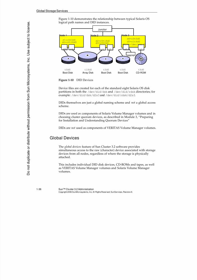
8/4/2019 Sun Cluster 3.2 Administration VC-ES-345
http://slidepdf.com/reader/full/sun-cluster-32-administration-vc-es-345 64/585
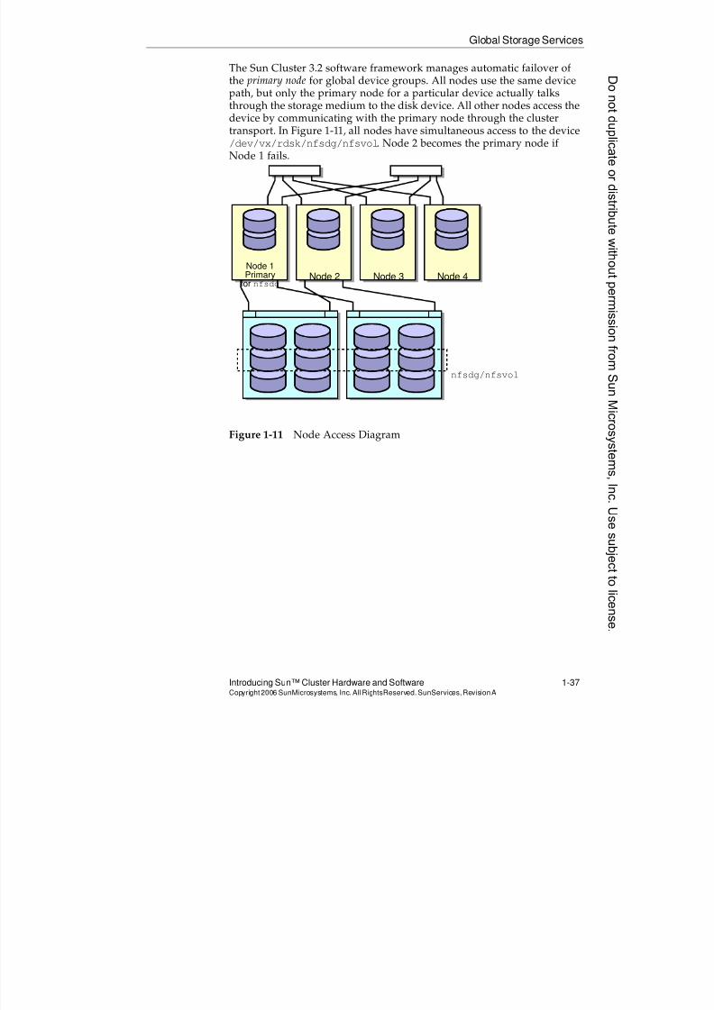
8/4/2019 Sun Cluster 3.2 Administration VC-ES-345
http://slidepdf.com/reader/full/sun-cluster-32-administration-vc-es-345 65/585
Global Storage Services
Introducing Sun™ Cluster Hardware and Software 1-37Copyright2006 SunMicrosystems, Inc. AllRightsReserved. SunServices,RevisionA
The Sun Cluster 3.2 software framework manages automatic failover ofthe primary node for global device groups. All nodes use the same devicepath, but only the primary node for a particular device actually talksthrough the storage medium to the disk device. All other nodes access thedevice by communicating with the primary node through the cluster
transport. In Figure 1-11, all nodes have simultaneous access to the device/dev/vx/rdsk/nfsdg/nfsvol. Node 2 becomes the primary node ifNode 1 fails.
Figure 1-11 Node Access Diagram
Node 1
Primaryfor nfsdg
Node 2 Node 3 Node 4
nfsdg/nfsvol
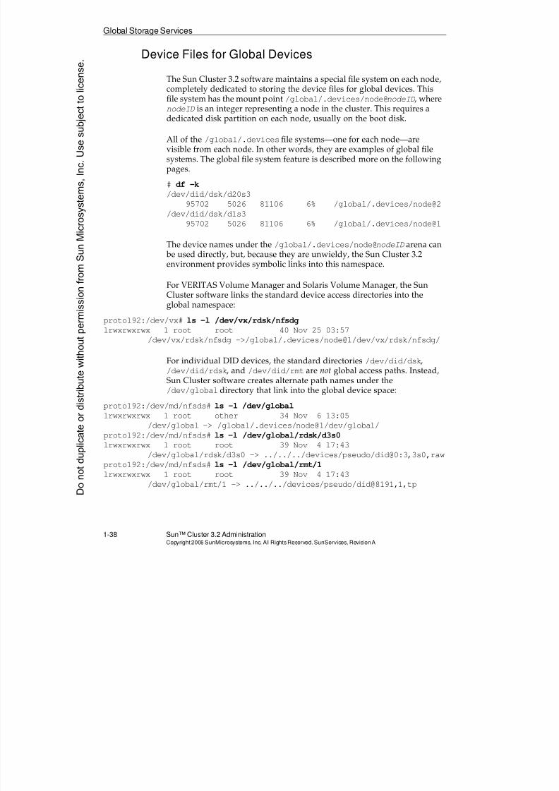
8/4/2019 Sun Cluster 3.2 Administration VC-ES-345
http://slidepdf.com/reader/full/sun-cluster-32-administration-vc-es-345 66/585
8/4/2019 Sun Cluster 3.2 Administration VC-ES-345
http://slidepdf.com/reader/full/sun-cluster-32-administration-vc-es-345 67/585
8/4/2019 Sun Cluster 3.2 Administration VC-ES-345
http://slidepdf.com/reader/full/sun-cluster-32-administration-vc-es-345 68/585
Global Storage Services
1-40 Sun™ Cluster 3.2 AdministrationCopyright2006 SunMicrosystems, Inc. AllRights Reserved.SunServices,RevisionA
Failover (Non-Global) File Systems in the Cluster
Sun Cluster 3.2 software also has support in the cluster for failover filesystem access. Failover file systems are available only on one node at atime, on a node which is running a service and has a physical connection
to the storage in question.
In Sun Cluster 3.2 more file system types are supported as a failover filesystem than are supported as underlying file systems for a global filesystem. These are the supported types for failover file systems:
q UFS
q VxFS
q Sun StorageTek™ QFS software
q Solaris™ ZFS (Solaris 10 OS only)
Note – Officially, the acronyms QFS and ZFS do not stand for anything.
Failover File System Access IsNot for Scalable Services
Failover file system access is appropriate for failover services that run
only on the nodes physically connected to storage devices.
Failover file system access is not suitable for scalable services.
Failover file system access, when used appropriately, can have aperformance benefit over global file system access. There is overhead inthe global file system infrastructure of maintaining replicated stateinformation on multiple nodes simultaneously.
Donotduplicate
ordistributewithoutpermissionfrom SunMicrosystems,Inc.Usesubject
tolicense.
8/4/2019 Sun Cluster 3.2 Administration VC-ES-345
http://slidepdf.com/reader/full/sun-cluster-32-administration-vc-es-345 69/585

8/4/2019 Sun Cluster 3.2 Administration VC-ES-345
http://slidepdf.com/reader/full/sun-cluster-32-administration-vc-es-345 70/585
Exercise Summary
1-42 Sun™ Cluster 3.2 AdministrationCopyright2006 SunMicrosystems, Inc. AllRights Reserved.SunServices,RevisionA
Exercise Summary
?
!
Discussion – Take a few minutes to discuss what experiences, issues, ordiscoveries you had during the lab exercises.
q Experiences
q Interpretations
q Conclusions
q Applications
Donotduplicate
ordistributewithoutpermissionfrom SunMicrosystems,Inc.Usesubject
tolicense.
8/4/2019 Sun Cluster 3.2 Administration VC-ES-345
http://slidepdf.com/reader/full/sun-cluster-32-administration-vc-es-345 71/585
8/4/2019 Sun Cluster 3.2 Administration VC-ES-345
http://slidepdf.com/reader/full/sun-cluster-32-administration-vc-es-345 72/585
Relevance
2-2 Sun™Cluster 3 .2AdministrationCopyright2006 SunMicrosystems, Inc. AllRights Reserved.SunServices,RevisionA
Relevance
?
!
Discussion – The following questions are relevant to understanding thecontent of this module:
q What is the trade-off between convenience and security in differentconsole access methods?
q How do you reach the node console on domain-based clusters?
q What benefits does using a terminal concentrator give you?
q Is installation of the administration workstation software essentialfor proper cluster operation?
Donotduplicate
ordistributewithoutpermissionfrom SunMicrosystems,Inc.Usesubject
tolicense.
8/4/2019 Sun Cluster 3.2 Administration VC-ES-345
http://slidepdf.com/reader/full/sun-cluster-32-administration-vc-es-345 73/585
Additional Resources
Exploring Node Console Connectivity and the Cluster Console Software 2-3Copyright2006 SunMicrosystems, Inc. AllRightsReserved. SunServices,RevisionA
Additional Resources
Additional resources – The following references provide additional
information on the topics described in this module:q Sun Cluster System Administration Guide for Solaris OS, part number
819-2971.
q Sun Cluster Software Installation Guide for Solaris OS, part number 819-2970.
8/4/2019 Sun Cluster 3.2 Administration VC-ES-345
http://slidepdf.com/reader/full/sun-cluster-32-administration-vc-es-345 74/585
Accessing the Cluster Node Consoles
2-4 Sun™Cluster 3 .2AdministrationCopyright2006 SunMicrosystems, Inc. AllRights Reserved.SunServices,RevisionA
Accessing the Cluster Node Consoles
This section describes different methods for achieving access to the SunCluster 3.2 node consoles. It is expected that a Sun Cluster 3.2environment administrator:
q Does not require node console access for most operations describedduring the duration of the course. Most cluster operations requireonly that you be logged in on a cluster node as root or as a userwith cluster authorizations in the Role-Based Access Control (RBAC)subsystem. It is acceptable to have direct telnet, rlogin, or sshaccess to the node.
q Must have console node access for certain emergency andinformational purposes. If a node is failing to boot, the clusteradministrator will have to access the node console to figure out why.
The cluster administrator might like to observe boot messages evenin normal, functioning clusters.
The following pages describe the essential difference between consoleconnectivity on traditional nodes that are not domain-based and consoleconnectivity on the domain-based nodes (Sun Enterprise 10000 servers,Sun Fire midrange servers (E4900, E6900, and 3800 through 6800 servers),and Sun Fire high-end servers 25K/20K/15K/12K servers).
Accessing Serial Port Consoles on Traditional Nodes
Traditional Sun Cluster 3.2 nodes usually use serial port ttyA as theconsole.
Even if you have a graphics monitor and system keyboard you aresupposed to redirect console access to the serial port or emulation thereof.
Donotduplicate
ordistributewithoutpermissionfrom SunMicrosystems,Inc.Usesubject
tolicense.
8/4/2019 Sun Cluster 3.2 Administration VC-ES-345
http://slidepdf.com/reader/full/sun-cluster-32-administration-vc-es-345 75/585
Accessing the Cluster Node Consoles
Exploring Node Console Connectivity and the Cluster Console Software 2-5Copyright2006 SunMicrosystems, Inc. AllRightsReserved. SunServices,RevisionA
The rule for console connectivity is simple. You can connect to the nodettyA interfaces any way you prefer, if whatever device you haveconnected directly to the interfaces does not spuriously issue BREAKsignals on the serial line.
BREAK signals on the serial port bring a cluster node to the OK prompt,killing all cluster operations on that node.
You can disable node recognition of a BREAK signal by a hardwarekeyswitch position (on some nodes), a software keyswitch position (onmidrange and high-end sersvers), or a file setting (on all nodes).
For those servers with a hardware keyswitch, turn the key to the thirdposition to power the server on and disable the BREAK signal.
For those servers with a software keyswitch, issue the setkeyswitch
command with the secure option to power the server on and disable theBREAK signal.
For all servers, while running Solaris OS, uncomment the lineKEYBOARD_ABORT=alternate in /etc/default/kbd to disablereceipt of the normal BREAK signal through the serial port. This settingtakes effect on boot, or by running the kbd -i command as root.
The Alternate Break signal is defined by the particular serial portdriver you happen to have on your system. You can use the prtconf
command to figure out the name of your serial port driver, and then useman serial-driver to figure out the sequence. For example, for the zs
driver, the sequence is carriage return, tilde (~), and control-B: CR ~CTRL-B. When the Alternate Break sequence is in effect, only serialconsole devices are affected.
Accessing Serial Port Node Consoles Using a TerminalConcentrator
One of the popular ways of accessing traditional node consoles is througha TC, a device which listens for connections on the network and passesthrough traffic (unencapsulating and reencapsulating all the TCP/IPheaders) to the various serial ports.
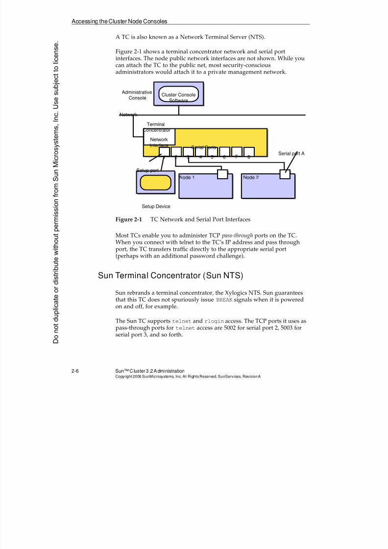
8/4/2019 Sun Cluster 3.2 Administration VC-ES-345
http://slidepdf.com/reader/full/sun-cluster-32-administration-vc-es-345 76/585
Accessing the Cluster Node Consoles
2-6 Sun™Cluster 3 .2AdministrationCopyright2006 SunMicrosystems, Inc. AllRights Reserved.SunServices,RevisionA
A TC is also known as a Network Terminal Server (NTS).
Figure 2-1 shows a terminal concentrator network and serial portinterfaces. The node public network interfaces are not shown. While youcan attach the TC to the public net, most security-conscious
administrators would attach it to a private management network.
Figure 2-1 TC Network and Serial Port Interfaces
Most TCs enable you to administer TCP pass-through ports on the TC.When you connect with telnet to the TC’s IP address and pass throughport, the TC transfers traffic directly to the appropriate serial port(perhaps with an additional password challenge).
Sun Terminal Concentrator (Sun NTS)
Sun rebrands a terminal concentrator, the Xylogics NTS. Sun guaranteesthat this TC does not spuriously issue BREAK signals when it is poweredon and off, for example.
The Sun TC supports telnet and rlogin access. The TCP ports it uses aspass-through ports for telnet access are 5002 for serial port 2, 5003 forserial port 3, and so forth.
AdministrativeConsole
TerminalConcentrator
Network
Cluster ConsoleSoftware
Setup port
Setup Device
Serial port A
Node 1 Node 2
NetworkInterface
Serial Ports
1 2 3 4 5 6 7 8
Donotduplicate
ordistributewithoutpermissionfrom SunMicrosystems,Inc.Usesubject
tolicense.
8/4/2019 Sun Cluster 3.2 Administration VC-ES-345
http://slidepdf.com/reader/full/sun-cluster-32-administration-vc-es-345 77/585
Accessing the Cluster Node Consoles
Exploring Node Console Connectivity and the Cluster Console Software 2-7Copyright2006 SunMicrosystems, Inc. AllRightsReserved. SunServices,RevisionA
When you use telnet to connect to the Sun TC from an administrativeworkstation using, for example, the following command, the Sun TCpasses you directly to serial port 2, connected to your first cluster node.
# telnet tc-ipname 5002
The Sun TC supports an extra level of password challenge, a per-portpassword that you have to enter before going through to the serial port.
Full instructions about installing and configuring the Sun TC are inAppendix A, “Terminal Concentrator.”
Other Terminal Concentrators
You can choose any type of TC as long as it does not issue BREAK signals
on the serial ports when it is powered on, powered off, reset, or any othertime that might be considered spurious.
If your TC cannot meet that requirement, you can still disable recognitionof the BREAK signal or enable an alternate abort signal for your node.
Some terminal concentrators support Secure Shell (the Sun NTS does notsupport Secure Shell). This might influence your choice, if you areconcerned about passing TC traffic in the clear on the network.
8/4/2019 Sun Cluster 3.2 Administration VC-ES-345
http://slidepdf.com/reader/full/sun-cluster-32-administration-vc-es-345 78/585
Accessing the Cluster Node Consoles
2-8 Sun™Cluster 3 .2AdministrationCopyright2006 SunMicrosystems, Inc. AllRights Reserved.SunServices,RevisionA
Alternatives to a Terminal Concentrator (TC)
Some possible alternatives to the terminal concentrator (TC) include thefollowing:
q Use dumb terminals for each node console. If these are in a securephysical environment, this is certainly the most secure, but leastconvenient, method.
q Use a workstation that has two serial ports as a tip launchpad,especially for a cluster with only two nodes.
You can attach a workstation on the network exactly as you wouldplace a TC, and attach its serial ports to the node consoles. You thenadd lines to the /etc/remote file of the Solaris OS workstation asfollows:
node1:\
:dv=/dev/term/a:br#9600:el=^C^S^Q̂ U^D:ie=%$:oe=^D:
node2:\
:dv=/dev/term/b:br#9600:el=^C^S^Q̂ U^D:ie=%$:oe=^D:
This allows you to access node consoles by accessing the launchpadworkstation and manually typing tip node1 or tip node2.
One advantage of using a Solaris OS workstation instead of a TC isthat it is easier to tighten the security in the Solaris OS workstation.For example, you could easily disable telnet and rlogin access andrequire that administrators access the tip launchpad through SecureShell.
q Use network access to the console on servers that specificallysupport the following types of remote control:
q Advanced Lights Out Manager (ALOM)
q Remote System Control (RSC)
q Service Processor (on Sun Fire server V40z x86 nodes)
These servers provide a combination of firmware and hardware thatprovides direct access to the server’s hardware and console.Dedicated Ethernet ports and dedicated IP addresses are used for
remote console access and server management.
Donotduplicate
ordistributewithoutpermissionfrom SunMicrosystems,Inc.Usesubject
tolicense.
8/4/2019 Sun Cluster 3.2 Administration VC-ES-345
http://slidepdf.com/reader/full/sun-cluster-32-administration-vc-es-345 79/585
Accessing theNode Consoleson Domain-BasedServers
Exploring Node Console Connectivity and the Cluster Console Software 2-9Copyright2006 SunMicrosystems, Inc. AllRightsReserved. SunServices,RevisionA
Accessing the Node Consoles on Domain-Based Servers
Domain-based servers have no serial port console access for the domains.Instead, you access the main system support processor (SSP) forSun Enterprise 10000 servers or system controller (SC) for Sun Fireservers. You use a virtual console protocol to access the console for eachnode.
Sun Enterprise 10000 Servers
The SSP and its backup sit physically outside the server frame and run theSolaris OS and SSP software.
To access the node console, you must always log in to the SSP manually as
the user named ssp and manually invoke the netcon command for theappropriate domain.
Sun Fire High-End Servers
The SC and its backup sit physically inside the server frame, but act muchlike the Sun Enterprise 10000 system SSP. They run the Solaris OS withSystem Management Services (SMS) software.
To access the node console, you must log in to the SC manually as thedomain administrator for the node in question (this can be a different userfor each domain) and manually invoke the console command for theappropriate domain.
Sun Fire Midrange Servers
The SC and its backup sit physically inside the server frame. They run aunique, firmware-based operating environment known as VxWorks. TheSCs run an application, based on Java technology, known as ScApp that is
dedicated to managing the server.
8/4/2019 Sun Cluster 3.2 Administration VC-ES-345
http://slidepdf.com/reader/full/sun-cluster-32-administration-vc-es-345 80/585
Accessing the Node Consoles on Domain-Based Servers
2-10 Sun™ Cluster 3.2 AdministrationCopyright2006 SunMicrosystems, Inc. AllRights Reserved.SunServices,RevisionA
You can configure ScApp to provide remote access through telnet,through ssh, or neither. If you configure telnet access, the SC runs anemulation that is similar to the TC, where it listens on TCP ports 5001,5002, and so forth. Accessing the SC with one of these ports passes youthrough (perhaps with an extra password challenge) to a domain console
or domain shell.
Donotduplicate
ordistributewithoutpermissionfrom SunMicrosystems,Inc.Usesubject
tolicense.
8/4/2019 Sun Cluster 3.2 Administration VC-ES-345
http://slidepdf.com/reader/full/sun-cluster-32-administration-vc-es-345 81/585
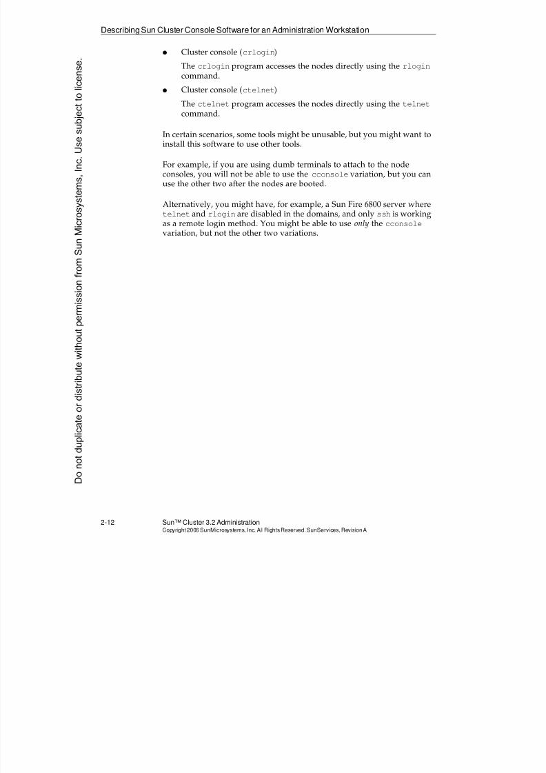
8/4/2019 Sun Cluster 3.2 Administration VC-ES-345
http://slidepdf.com/reader/full/sun-cluster-32-administration-vc-es-345 82/585
DescribingSun Cluster Console Software for an Administration Workstation
2-12 Sun™ Cluster 3.2 AdministrationCopyright2006 SunMicrosystems, Inc. AllRights Reserved.SunServices,RevisionA
q Cluster console (crlogin)
The crlogin program accesses the nodes directly using the rlogincommand.
q Cluster console (ctelnet)
The ctelnet program accesses the nodes directly using the telnetcommand.
In certain scenarios, some tools might be unusable, but you might want toinstall this software to use other tools.
For example, if you are using dumb terminals to attach to the nodeconsoles, you will not be able to use the cconsole variation, but you canuse the other two after the nodes are booted.
Alternatively, you might have, for example, a Sun Fire 6800 server wheretelnet and rlogin are disabled in the domains, and only ssh is workingas a remote login method. You might be able to use only the cconsolevariation, but not the other two variations.
Donotduplicate
ordistributewithoutpermissionfrom SunMicrosystems,Inc.Usesubject
tolicense.
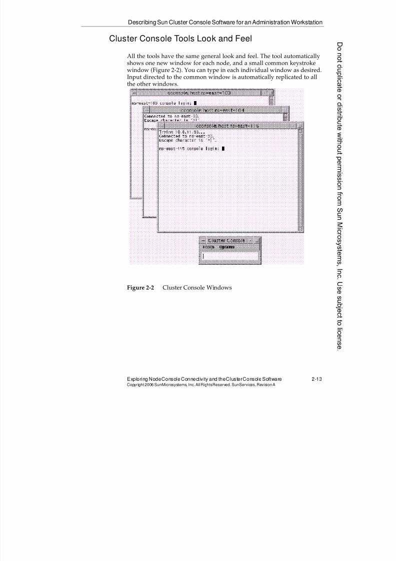
8/4/2019 Sun Cluster 3.2 Administration VC-ES-345
http://slidepdf.com/reader/full/sun-cluster-32-administration-vc-es-345 83/585
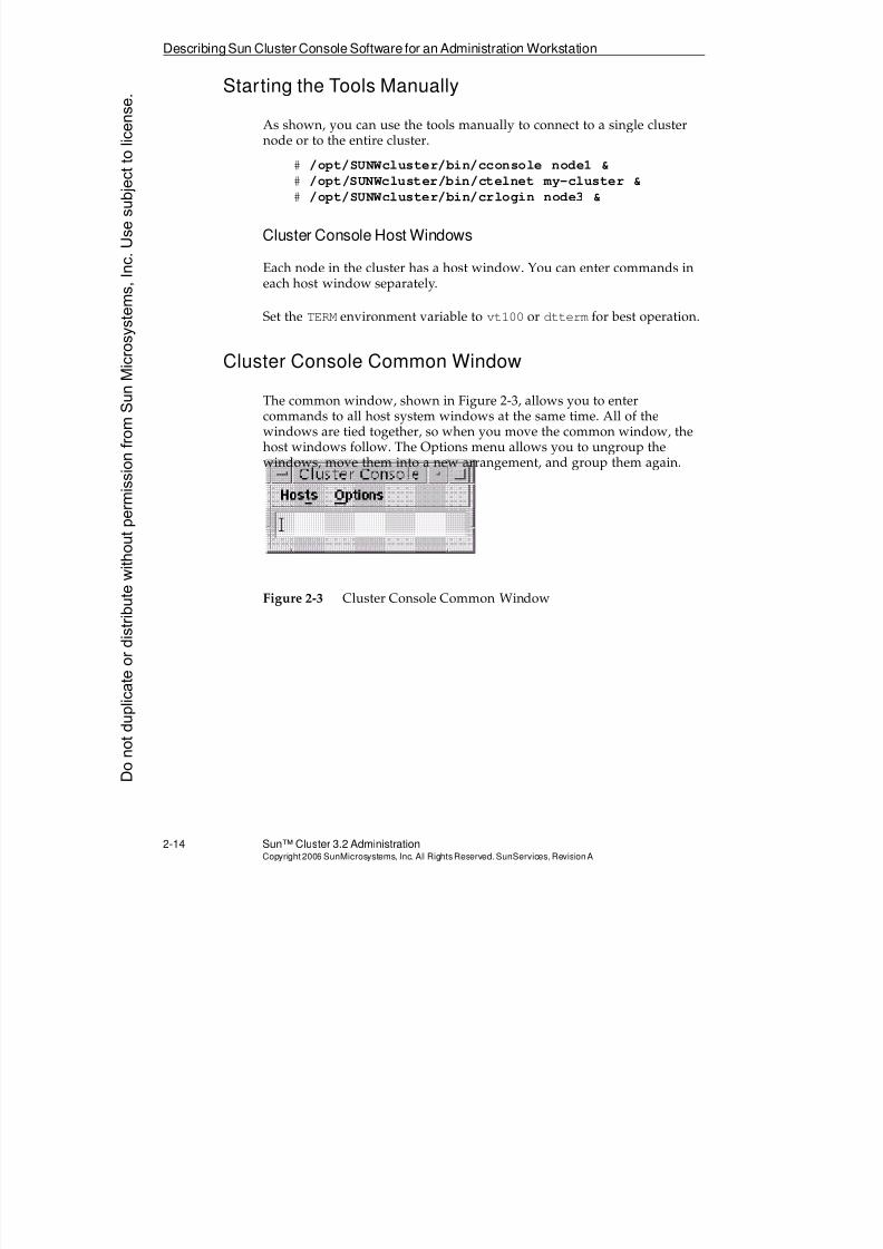
8/4/2019 Sun Cluster 3.2 Administration VC-ES-345
http://slidepdf.com/reader/full/sun-cluster-32-administration-vc-es-345 84/585
8/4/2019 Sun Cluster 3.2 Administration VC-ES-345
http://slidepdf.com/reader/full/sun-cluster-32-administration-vc-es-345 85/585
8/4/2019 Sun Cluster 3.2 Administration VC-ES-345
http://slidepdf.com/reader/full/sun-cluster-32-administration-vc-es-345 86/585
Configuring Cluster Console Tools
2-16 Sun™ Cluster 3.2 AdministrationCopyright2006 SunMicrosystems, Inc. AllRights Reserved.SunServices,RevisionA
Configuring Cluster Console Tools
All the information needed for the cluster administration tools that run onthe administrative console is configured in two files. The files are:
q The /etc/clusters fileq The /etc/serialportsfile (for cconsole variation only)
When you install the Sun Cluster console software on the administrativeconsole, you must manually create the clusters and serialports filesand populate them with the necessary information.
Configuring the /etc/clustersFile
The /etc/clusters file contains the name of a cluster followed by thenames of the nodes that are part of the cluster.
The following is a typical entry in the /etc/clusters file:
sc-cluster sc-node1 sc-node2
The single-line entry defines a cluster named sc-cluster, which has twonodes named sc-node1 and sc-node2.
Note – The cluster name is purely arbitrary. The Sun Cluster 3.2 softwareitself requires you to define a cluster name, which will likely agree withthis one, although nothing will break if it does not agree.
You can define many different clusters in a single /etc/clusters file, soyou can administer several clusters from a single administrative console.
Donotduplicate
ordistributewithoutpermissionfrom SunMicrosystems,Inc.Usesubject
tolicense.
8/4/2019 Sun Cluster 3.2 Administration VC-ES-345
http://slidepdf.com/reader/full/sun-cluster-32-administration-vc-es-345 87/585
ConfiguringCluster Console Tools
Exploring NodeConsole Connectivity and theClusterConsole Software 2-17Copyright2006 SunMicrosystems, Inc. AllRightsReserved. SunServices,RevisionA
Configuring the /etc/serialportsFile
The /etc/serialports file defines the remote path to the console foreach node defined in the /etc/clustersfile. You must enter the paths toall nodes in all of your clusters in this file. This file uses three columns: the
node name listed in /etc/inet/hosts, the host name of theworkstation or device providing the connection as listed in/etc/inet/hosts, and the port for telnet to use for the connection toor through this device.
The following are typical entries in the /etc/serialports file whenusing a terminal concentrator to pass through to the physical serialconnection (ttyA) on each cluster node:
sc-node1 sc-tc 5002
sc-node2 sc-tc 5003
For the Sun Enterprise 10000 server, the columns are the name of thedomain, the name of the SSP workstation, and port 23. When thecconsole cluster command is executed, you are connected to port 23on the SSP. This opens up a telnet session for each domain listed. Theactual login to the SSP is performed manually in each window. After login, a netcon session is manually started for the domain in each window.
sc-10knode1 sc10k-ssp 23
sc-10knode2 sc10k-ssp 23
For the Sun Fire 25K/20K/15K/12K server, the columns are the name ofthe domain, the name of the main system controller, and port 23. Whenthe cconsole cluster command is executed, you are connected toport 23 on the main system controller. This opens up a telnet session foreach domain listed. The actual login to the main system controller isperformed manually in each window using the login of the domainadministrator for that domain. After log in, a console session ismanually started for that domain.
sc-15knode1 sf15k-mainsc 23
sc-15knode2 sf15k-mainsc 23
8/4/2019 Sun Cluster 3.2 Administration VC-ES-345
http://slidepdf.com/reader/full/sun-cluster-32-administration-vc-es-345 88/585
Configuring Cluster Console Tools
2-18 Sun™ Cluster 3.2 AdministrationCopyright2006 SunMicrosystems, Inc. AllRights Reserved.SunServices,RevisionA
For a system using ALOM or RSC access instead of a TC, the columnsdisplay the name of the node, the name corresponding to the dedicated IPfor ALOM/RSC for that node, and port 23. When the cconsolecluster command is executed, you are connected to the ALOM or RSCfor that node. The actual login to the node console is performed manually
in each window.node1 node1-sc 23
node2 node2-sc 23
If you are using a tip launchpad, the columns display the name of thenode, the name of the launchpad, and port 23. The actual login to thelaunchpad is performed manually in each window. The actual connectionto each node console is made by executing the tip command andspecifying the serial port used for that node in each window.
node1 sc-tip-ws 23
node2 sc-tip-ws 23
For the Sun Fire 3800 through 6800 servers and E4900/E6900 servers, thecolumns display the domain name, the Sun Fire server main systemcontroller name, and a TCP port number similar to those used with aterminal concentrator. Port 5000 connects you to the platform shell, ports5001, 5002, 5003, or 5004 connect you to the domain shell or domainconsole for domains A, B, C, or D, respectively. Connection to the domainshell or console is dependent upon the current state of the domain.
sf1_node1 sf1_mainsc 5001
sf1_node2 sf1_mainsc 5002
Donotduplicate
ordistributewithoutpermissionfrom SunMicrosystems,Inc.Usesubject
tolicense.
8/4/2019 Sun Cluster 3.2 Administration VC-ES-345
http://slidepdf.com/reader/full/sun-cluster-32-administration-vc-es-345 89/585
ConfiguringCluster Console Tools
Exploring NodeConsole Connectivity and theClusterConsole Software 2-19Copyright2006 SunMicrosystems, Inc. AllRightsReserved. SunServices,RevisionA
Using the Tools When ssh Is Required or Preferred toAccess the Console
Certain environments might require ssh access to get to the console, or
you might prefer to usessh
access even iftelnet
is also available.Examples are:
q TCs that have ssh enabled
q The tip launchpad on which you have enabled ssh
q Sun high-end servers (ssh to the SC) and E10000 (ssh to the SSP)
q Sun Fire midrange SCs on which you have enabled ssh (telnetwill be automatically disabled)
q Sun Fire v40z service processor (supports only ssh, not telnet)
To use the tools in these scenarios, you can create an /etc/serialportsfile similar to the following:
# example for a 6800 (cluster in a box)node1 my6800sc 22node2 my6800sc 22
# example for a 15K (cluster in a box)node1 my15kmainsc 22node2 my15kmainsc 22
# example for two v40z’s (each has its own sp)
v40node1 node1-sp 22v40node2 node2-sp 22
Now create a file called, for example, /etc/consolewithssh. This is used by the customized telnet script below to figure out which console accessdevices require ssh access, and what the ssh user name should be. Thessh server on the Sun Fire midrange SC ignores the user name, so the file just includes anything as a place holder. A Sun Fire 15K SC would have auser defined on the SC (in this example, mysmsuser), that is defined as adomain administrator of both domains in question.
# console access device / user
my6800sc anything
node1-sp admin
node2-sp admin
my15kmainsc mysmsuser
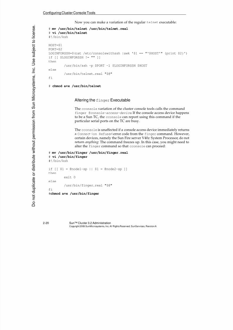
8/4/2019 Sun Cluster 3.2 Administration VC-ES-345
http://slidepdf.com/reader/full/sun-cluster-32-administration-vc-es-345 90/585
Configuring Cluster Console Tools
2-20 Sun™ Cluster 3.2 AdministrationCopyright2006 SunMicrosystems, Inc. AllRights Reserved.SunServices,RevisionA
Now you can make a variation of the regular telnet executable:
# mv /usr/bin/telnet /usr/bin/telnet.real
# vi /usr/bin/telnet
#!/bin/ksh
HOST=$1PORT=$2
LOGINFORSSH=$(cat /etc/consolewithssh |awk '$1 == "'$HOST'" {print $2}')
if [[ $LOGINFORSSH != "" ]]
then
/usr/bin/ssh -p $PORT -l $LOGINFORSSH $HOST
else
/usr/bin/telnet.real "$@"
fi
# chmod a+x /usr/bin/telnet
Altering thefingerExecutable
The cconsole variation of the cluster console tools calls the commandfinger @console-access-device. If the console access device happensto be a Sun TC, the cconsole can report using this command if theparticular serial ports on the TC are busy.
The cconsole is unaffected if a console access device immediately returns
a Connection Refused error code from the finger command. However,certain devices, namely the Sun Fire server V40z System Processor, do notreturn anything: The command freezes up. In this case, you might need toalter the finger command so that cconsole can proceed:
# mv /usr/bin/finger /usr/bin/finger.real
# vi /usr/bin/finger
#!/bin/ksh
if [[ $1 = @node1-sp || $1 = @node2-sp ]]
then
exit 0else
/usr/bin/finger.real "$@"
fi
#chmod a+x /usr/bin/finger
Donotduplicate
ordistributewithoutpermissionfrom SunMicrosystems,Inc.Usesubject
tolicense.
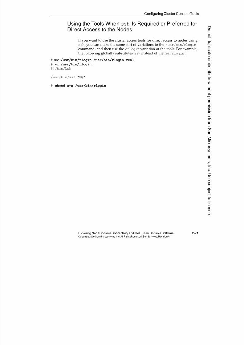
8/4/2019 Sun Cluster 3.2 Administration VC-ES-345
http://slidepdf.com/reader/full/sun-cluster-32-administration-vc-es-345 91/585
ConfiguringCluster Console Tools
Exploring NodeConsole Connectivity and theClusterConsole Software 2-21Copyright2006 SunMicrosystems, Inc. AllRightsReserved. SunServices,RevisionA
Using the Tools When ssh Is Required or Preferred forDirect Access to the Nodes
If you want to use the cluster access tools for direct access to nodes usingssh
, you can make the same sort of variations to the/usr/bin/rlogin
command, and then use the crlogin variation of the tools. For example,the following globally substitutes ssh instead of the real rlogin:
# mv /usr/bin/rlogin /usr/bin/rlogin.real
# vi /usr/bin/rlogin
#!/bin/ksh
/usr/bin/ssh "$@"
# chmod a+x /usr/bin/rlogin
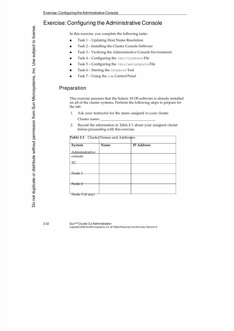
8/4/2019 Sun Cluster 3.2 Administration VC-ES-345
http://slidepdf.com/reader/full/sun-cluster-32-administration-vc-es-345 92/585
Exercise: Configuring the Administrative Console
2-22 Sun™ Cluster 3.2 AdministrationCopyright2006 SunMicrosystems, Inc. AllRights Reserved.SunServices,RevisionA
Exercise: Configuring the Administrative Console
In this exercise, you complete the following tasks:
q Task 1 – Updating Host Name Resolution
q Task 2 – Installing the Cluster Console Software
q Task 3 – Verifying the Administrative Console Environment
q Task 4 – Configuring the /etc/clusters File
q Task 5 – Configuring the /etc/serialports File
q Task 6 – Starting the cconsole Tool
q Task 7 – Using the ccp Control Panel
Preparation
This exercise assumes that the Solaris 10 OS software is already installedon all of the cluster systems. Perform the following steps to prepare forthe lab:
1. Ask your instructor for the name assigned to your cluster.
Cluster name: _______________________________
2. Record the information in Table 2-1 about your assigned cluster before proceeding with this exercise.
Table 2-1 Cluster Names and Addresses
System Name IP Address
Administrativeconsole
TC
Node 1
Node 2
Node 3 (if any)
Donotduplicate
ordistributewithoutpermissionfrom SunMicrosystems,Inc.Usesubject
tolicense.
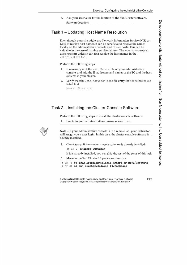
8/4/2019 Sun Cluster 3.2 Administration VC-ES-345
http://slidepdf.com/reader/full/sun-cluster-32-administration-vc-es-345 93/585
Exercise: Configuring the Administrative Console
Exploring NodeConsole Connectivity and theClusterConsole Software 2-23Copyright2006 SunMicrosystems, Inc. AllRightsReserved. SunServices,RevisionA
3. Ask your instructor for the location of the Sun Cluster software.
Software location: _______________________________
Task 1 – Updating Host Name Resolution
Even though your site might use Network Information Service (NIS) orDNS to resolve host names, it can be beneficial to resolve the nameslocally on the administrative console and cluster hosts. This can bevaluable in the case of naming service failures. The cconsole programdoes not start unless it can first resolve the host names in the/etc/clusters file.
Perform the following steps:
1. If necessary, edit the /etc/hosts file on your administrative
console, and add the IP addresses and names of the TC and the hostsystems in your cluster.
2. Verify that the /etc/nsswitch.conffile entry for hosts has fileslisted first.
hosts: files nis
Task 2 – Installing the Cluster Console Software
Perform the following steps to install the cluster console software:
1. Log in to your administrative console as user root.
Note – If your administrative console is in a remote lab, your instructorwill assign you a user login. In this case, the cluster console software isalready installed.
2. Check to see if the cluster console software is already installed:
(# or $) pkginfo SUNWccon
If it is already installed, you can skip the rest of the steps of this task.
3. Move to the Sun Cluster 3.2 packages directory:
(# or $) cd sc32_location/Solaris_{sparc_or_x86}/Products
(# or $) cd sun_cluster/Solaris_10/Packages
8/4/2019 Sun Cluster 3.2 Administration VC-ES-345
http://slidepdf.com/reader/full/sun-cluster-32-administration-vc-es-345 94/585
Exercise: Configuring the Administrative Console
2-24 Sun™ Cluster 3.2 AdministrationCopyright2006 SunMicrosystems, Inc. AllRights Reserved.SunServices,RevisionA
4. Verify that you are in the correct location:
# ls -d SUNWccon
SUNWccon
5. Install the cluster console software package:
# pkgadd -d . SUNWccon
Task 3 – Verifying the Administrative ConsoleEnvironment
Perform the following steps to verify the administrative console:
1. Verify that the following search paths and variables are present inthe .profile file in your home directory:
PATH=$PATH:/opt/SUNWcluster/bin
MANPATH=$MANPATH:/opt/SUNWcluster/man
export PATH MANPATH
Note – Create the .profile file in your home directory if necessary, andadd the changes.
2. Execute the .profile file to verify changes that have been made:
(# or $) $HOME/.profile
Note – You can also log out and log in again to set the new variables.
Task 4 – Configuring the /etc/clustersFile
The /etc/clustersfile has a single line entry for each cluster you intendto monitor. The entries are in the form:
clustername host1name host2name host3name host4name
Sample /etc/clusters File
sc-cluster pnode1 pnode2 pnode3
Donotduplicate
ordistributewithoutpermissionfrom SunMicrosystems,Inc.Usesubject
tolicense.
8/4/2019 Sun Cluster 3.2 Administration VC-ES-345
http://slidepdf.com/reader/full/sun-cluster-32-administration-vc-es-345 95/585
8/4/2019 Sun Cluster 3.2 Administration VC-ES-345
http://slidepdf.com/reader/full/sun-cluster-32-administration-vc-es-345 96/585
Exercise: Configuring the Administrative Console
2-26 Sun™ Cluster 3.2 AdministrationCopyright2006 SunMicrosystems, Inc. AllRights Reserved.SunServices,RevisionA
Task 6 – Starting the cconsoleTool
This section provides a good functional verification of the TC in additionto the environment configuration.
Perform the following steps to start the cconsole tool:
1. Make sure power is on for the TC and all of the cluster hosts.
2. Start the cconsole tool on the administrative console:
(# or $) cconsole clustername &
Note – Substitute the name of your cluster for clustername.
3. Place the cursor in the cconsole Common window, and press the
Return key several times. You should see a response on all of thecluster host windows. If not, ask your instructor for assistance.
4. If your console device is an ALOM dedicated interface, you mightneed to enter an ALOM command to access the actual node consoles.Consult your instructor.
5. If the cluster host systems are not booted, boot them now.
ok boot
6. After all cluster host systems have completed their boot, log in asuser root.
7. Practice using the Common window Group Term Windows featureunder the Options menu. You can ungroup the cconsole windows,rearrange them, and then group them together again.
Task 7 – Using the ccpControl Panel
The ccp control panel can be useful if you must use the console toolvariations crlogin and ctelnet.
Perform the following steps to use the ccp control panel:
1. Start the ccp tool (ccp clustername &).
2. Practice using the crlogin and ctelnet console tool variations.
3. Quit the crlogin, ctelnet, and ccp tools.
Donotduplicate
ordistributewithoutpermissionfrom SunMicrosystems,Inc.Usesubject
tolicense.
8/4/2019 Sun Cluster 3.2 Administration VC-ES-345
http://slidepdf.com/reader/full/sun-cluster-32-administration-vc-es-345 97/585

8/4/2019 Sun Cluster 3.2 Administration VC-ES-345
http://slidepdf.com/reader/full/sun-cluster-32-administration-vc-es-345 98/585
Do not duplicate or distribute without permission from Sun Microsystems, Inc. U
8/4/2019 Sun Cluster 3.2 Administration VC-ES-345
http://slidepdf.com/reader/full/sun-cluster-32-administration-vc-es-345 99/585
3-1Copyright2006 SunMicrosystems, Inc. AllRights Reserved.SunServices,RevisionA
Module 3
Preparing for InstallationandUnderstandingQuorum Devices
Objectives
Upon completion of this module, you should be able to:
q List the Sun Cluster software boot disk requirements and hardwarerestrictions
q Identify typical cluster storage topologies
q Describe quorum votes and quorum devices
q Describe persistent quorum reservations and cluster amnesia
q Describe data fencing
q Configure a supported cluster interconnect system
q
Identify public network adaptersq Configure shared physical adapters
8/4/2019 Sun Cluster 3.2 Administration VC-ES-345
http://slidepdf.com/reader/full/sun-cluster-32-administration-vc-es-345 100/585
Relevance
3-2 Sun™Cluster 3 .2AdministrationCopyright2006 SunMicrosystems, Inc. AllRights Reserved.SunServices,RevisionA
Relevance
?
!
Discussion – The following questions are relevant to understanding thecontent of this module:
q Is cluster planning required even before installation of the Solaris OSon a node?
q Do certain cluster topologies enforce which applications are going torun on which nodes, or do they just suggest this relationship?
q Why is a quorum device absolutely required in a two-node cluster?
q What is meant by a cluster amnesia problem?
Donotduplicate
ordistributewithoutpermissionfrom SunMicrosystems,Inc.Usesubject
tolicense.

8/4/2019 Sun Cluster 3.2 Administration VC-ES-345
http://slidepdf.com/reader/full/sun-cluster-32-administration-vc-es-345 101/585
8/4/2019 Sun Cluster 3.2 Administration VC-ES-345
http://slidepdf.com/reader/full/sun-cluster-32-administration-vc-es-345 102/585
Configuring Cluster Servers
3-4 Sun™Cluster 3 .2AdministrationCopyright2006 SunMicrosystems, Inc. AllRights Reserved.SunServices,RevisionA
Configuring Cluster Servers
The servers you use in a Sun Cluster 3.2 hardware configuration mustconform to a number of general software and hardware requirements toqualify for support. The requirements include both hardware andsoftware in the following areas:
q Boot device restrictions
q Server hardware restrictions
Boot Device Restrictions
With the Sun Cluster 3.2 software release, there are several restrictions on boot devices including the following:
q You cannot use a shared storage device as a boot device. If a storagedevice is connected to more than one host, it is shared.
q The Solaris 9 OS 9/05 (Update 8), and Solaris 10 OS 11/06 (Update 3)or greater are supported with the following restrictions:
q The same version of the Solaris OS, including the updaterevision (for example, Solaris 10 11/06), must be installed on allnodes in the cluster.
q VERITAS Dynamic Multipathing (DMP) is not supported.
See Module 6, “Using VERITAS Volume Manager With SunCluster Software” for more details about this restriction.
The supported versions of VERITAS Volume Manager musthave the DMP device drivers enabled, but Sun Cluster 3.2software still does not support an actual multipathing topologyunder control of Volume Manager DMP.
q The boot disk partitions have the following requirements:
q Sun Cluster 3.2 software requires a minimum swap partition of750 megabytes (Mbytes).
q
There must be a minimum 512 Mbytes perglobaldevices
filesystem.
q Solaris Volume Manager software requires a 20 Mbyte partitionfor its meta-state databases.
q VERITAS Volume Manager software requires two unusedpartitions for encapsulation of the boot disk.
Donotduplicate
ordistributewithoutpermissionfrom SunMicrosystems,Inc.Usesubject
tolicense.
8/4/2019 Sun Cluster 3.2 Administration VC-ES-345
http://slidepdf.com/reader/full/sun-cluster-32-administration-vc-es-345 103/585
8/4/2019 Sun Cluster 3.2 Administration VC-ES-345
http://slidepdf.com/reader/full/sun-cluster-32-administration-vc-es-345 104/585
Configuring Cluster Servers
3-6 Sun™Cluster 3 .2AdministrationCopyright2006 SunMicrosystems, Inc. AllRights Reserved.SunServices,RevisionA
All cluster servers must meet the following minimum hardwarerequirements:
q Each server must have a minimum of 512 Mbytes of memory.
q Each server must have a minimum of 750 Mbytes of swap space. If
you are running applications on the cluster nodes that require swapspace, you should allocate at least 512 Mbytes over that requirementfor the cluster.
q Servers in a cluster can be heterogeneous with certain restrictions onmixing certain types of host adapters in the same cluster. Forexample, Peripheral Component Interconnect (PCI) and SBusadapters cannot be mixed in the same cluster if attached to smallcomputer system interface (SCSI) storage.
Donotduplicate
ordistributewithoutpermissionfrom SunMicrosystems,Inc.Usesubject
tolicense.
8/4/2019 Sun Cluster 3.2 Administration VC-ES-345
http://slidepdf.com/reader/full/sun-cluster-32-administration-vc-es-345 105/585
Configuring Cluster Storage Connections
Preparing for Installation and Understanding Quorum Devices 3-7Copyright2006 SunMicrosystems, Inc. AllRightsReserved. SunServices,RevisionA
Configuring Cluster Storage Connections
While previous versions of the Sun Cluster software had strict rulesregarding how many nodes were supported in various disk topologies,the only rules in the Sun Cluster 3.2 software regarding the data storagefor the cluster are the following:
q Sun Cluster software never supports more than sixteen nodes. Somestorage configurations have restrictions on the total number of nodessupported.
q A shared storage device can connect to as many nodes as the storagedevice supports.
q Shared storage devices do not need to connect to all nodes of thecluster. However, these storage devices must connect to at least twonodes.
Cluster Topologies
Cluster topologies describe typical ways in which cluster nodes can beconnected to data storage devices. While Sun Cluster does not require youto configure a cluster by using specific topologies, the followingtopologies are described to provide the vocabulary to discuss a cluster’sconnection scheme. The following are some typical topologies:
q Clustered pairs topology
q Pair+N topology
q N+1 topology
q Multiported (more than two node) N*N scalable topology
q NAS device-only topology
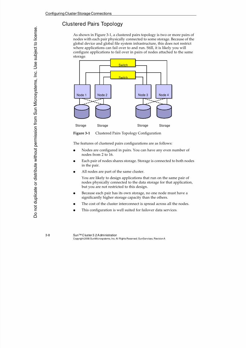
8/4/2019 Sun Cluster 3.2 Administration VC-ES-345
http://slidepdf.com/reader/full/sun-cluster-32-administration-vc-es-345 106/585
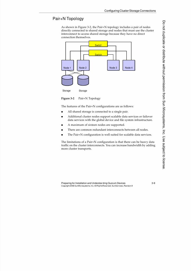
8/4/2019 Sun Cluster 3.2 Administration VC-ES-345
http://slidepdf.com/reader/full/sun-cluster-32-administration-vc-es-345 107/585
Configuring Cluster Storage Connections
Preparing for Installation and Understanding Quorum Devices 3-9Copyright2006 SunMicrosystems, Inc. AllRightsReserved. SunServices,RevisionA
Pair+N Topology
As shown in Figure 3-2, the Pair+N topology includes a pair of nodesdirectly connected to shared storage and nodes that must use the clusterinterconnect to access shared storage because they have no direct
connection themselves.
Figure 3-2 Pair+N Topology
The features of the Pair+N configurations are as follows:
q All shared storage is connected to a single pair.
q Additional cluster nodes support scalable data services or failoverdata services with the global device and file system infrastructure.
q A maximum of sixteen nodes are supported.
q There are common redundant interconnects between all nodes.
q The Pair+N configuration is well suited for scalable data services.
The limitations of a Pair+N configuration is that there can be heavy data
traffic on the cluster interconnects. You can increase bandwidth by addingmore cluster transports.
Switch
Switch
Node 1 Node 2 Node 3 Node 4
Storage Storage
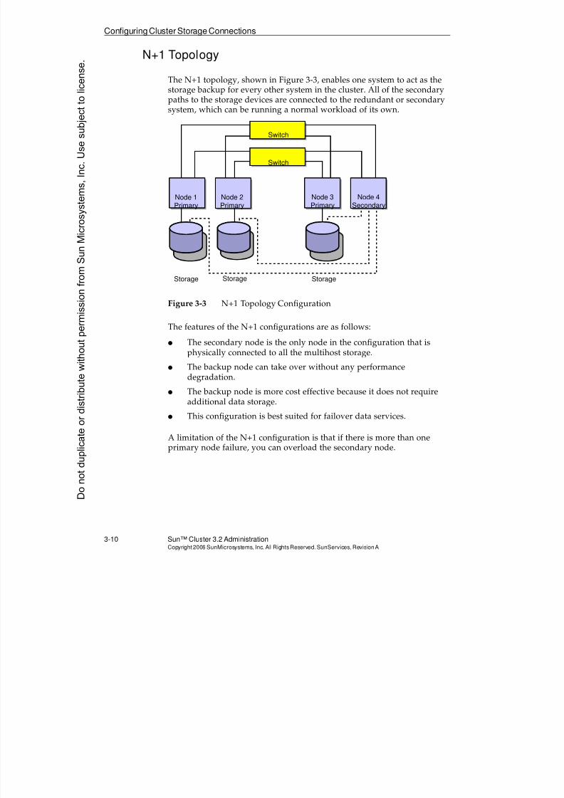
8/4/2019 Sun Cluster 3.2 Administration VC-ES-345
http://slidepdf.com/reader/full/sun-cluster-32-administration-vc-es-345 108/585
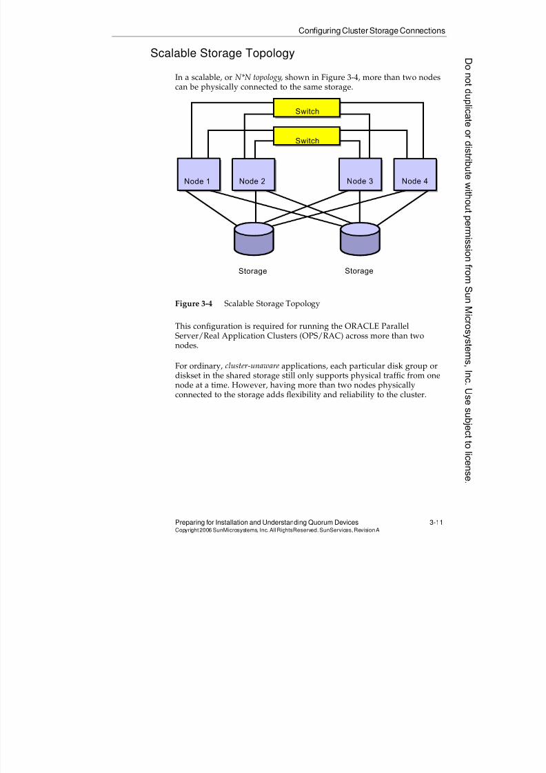
8/4/2019 Sun Cluster 3.2 Administration VC-ES-345
http://slidepdf.com/reader/full/sun-cluster-32-administration-vc-es-345 109/585
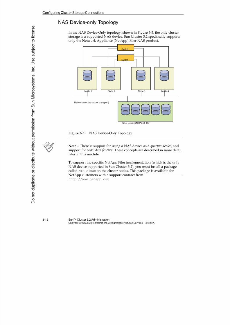
8/4/2019 Sun Cluster 3.2 Administration VC-ES-345
http://slidepdf.com/reader/full/sun-cluster-32-administration-vc-es-345 110/585
Configuring Cluster Storage Connections
3-12 Sun™ Cluster 3.2 AdministrationCopyright2006 SunMicrosystems, Inc. AllRights Reserved.SunServices,RevisionA
NAS Device-only Topology
In the NAS Device-Only topology, shown in Figure 3-5, the only clusterstorage is a supported NAS device. Sun Cluster 3.2 specifically supportsonly the Network Appliance (NetApp) Filer NAS product.
Figure 3-5 NAS Device-Only Topology
Note – There is support for using a NAS device as a quorum device, andsupport for NAS data fencing. These concepts are described in more detaillater in this module.
To support the specific NetApp Filer implementation (which is the onlyNAS device supported in Sun Cluster 3.2), you must install a packagecalled NTAPclnas on the cluster nodes. This package is available for
NetApp customers with a support contract fromhttp://now.netapp.com.
Network (not the cluster transport)
Node 1 Node 2 Node 3 Node 4
Switch
Switch
NAS Device (NetApp Filer )
Donotduplicate
ordistributewithoutpermissionfrom SunMicrosystems,Inc.Usesubject
tolicense.
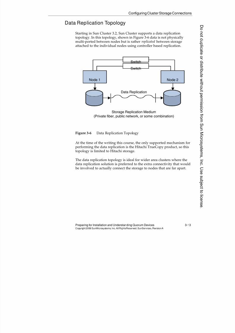
8/4/2019 Sun Cluster 3.2 Administration VC-ES-345
http://slidepdf.com/reader/full/sun-cluster-32-administration-vc-es-345 111/585
8/4/2019 Sun Cluster 3.2 Administration VC-ES-345
http://slidepdf.com/reader/full/sun-cluster-32-administration-vc-es-345 112/585
8/4/2019 Sun Cluster 3.2 Administration VC-ES-345
http://slidepdf.com/reader/full/sun-cluster-32-administration-vc-es-345 113/585
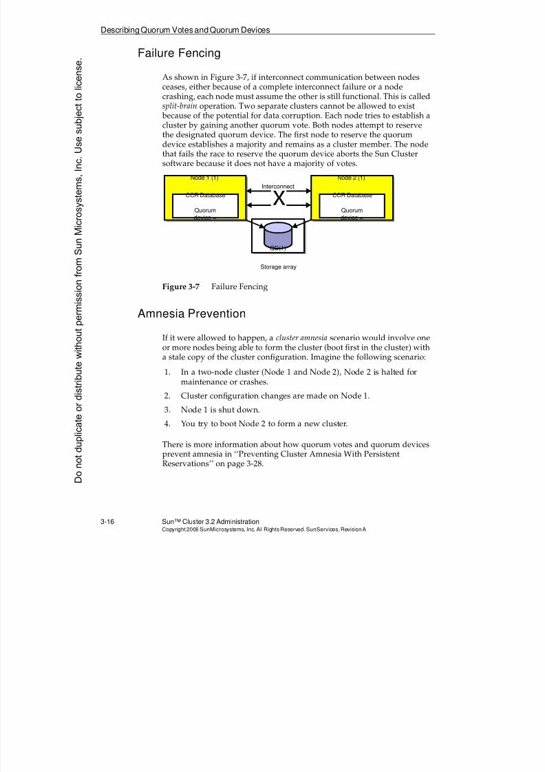
8/4/2019 Sun Cluster 3.2 Administration VC-ES-345
http://slidepdf.com/reader/full/sun-cluster-32-administration-vc-es-345 114/585
DescribingQuorum VotesandQuorum Devices
3-16 Sun™ Cluster 3.2 AdministrationCopyright2006 SunMicrosystems, Inc. AllRights Reserved.SunServices,RevisionA
Failure Fencing
As shown in Figure 3-7, if interconnect communication between nodesceases, either because of a complete interconnect failure or a nodecrashing, each node must assume the other is still functional. This is called
split-brain operation. Two separate clusters cannot be allowed to exist because of the potential for data corruption. Each node tries to establish acluster by gaining another quorum vote. Both nodes attempt to reservethe designated quorum device. The first node to reserve the quorumdevice establishes a majority and remains as a cluster member. The nodethat fails the race to reserve the quorum device aborts the Sun Clustersoftware because it does not have a majority of votes.
Figure 3-7 Failure Fencing
Amnesia Prevention
If it were allowed to happen, a cluster amnesia scenario would involve oneor more nodes being able to form the cluster (boot first in the cluster) witha stale copy of the cluster configuration. Imagine the following scenario:
1. In a two-node cluster (Node 1 and Node 2), Node 2 is halted formaintenance or crashes.
2. Cluster configuration changes are made on Node 1.
3. Node 1 is shut down.
4. You try to boot Node 2 to form a new cluster.
There is more information about how quorum votes and quorum devicesprevent amnesia in ‘‘Preventing Cluster Amnesia With PersistentReservations’’ on page 3-28.
CCR Database
Node 1 (1)
Quorumdevice =
CCR Database
Node 2 (1)
Quorumdevice =
Storage array
QD(1)
Interconnect
Donotduplicate
ordistributewithoutpermissionfrom SunMicrosystems,Inc.Usesubject
tolicense.
8/4/2019 Sun Cluster 3.2 Administration VC-ES-345
http://slidepdf.com/reader/full/sun-cluster-32-administration-vc-es-345 115/585
Describing Quorum Votes and Quorum Devices
Preparing for Installation and Understanding Quorum Devices 3-17Copyright2006 SunMicrosystems, Inc. AllRightsReserved. SunServices,RevisionA
Quorum Device Rules
The general rules for quorum devices are as follows:
q A quorum device must be available to both nodes in a two-node
cluster.q Quorum device information is maintained globally in the Cluster
Configuration Repository (CCR) database.
q A traditional disk quorum device can also contain user data.
q The maximum and optimal number of votes contributed by quorumdevices should be the number of node votes minus one (N-1).
If the number of quorum devices equals or exceeds the number ofnodes, the cluster cannot come up if too many quorum devices fail,even if all nodes are available. Clearly, this is unacceptable.
q Quorum devices are not required in clusters with greater than twonodes, but they are recommended for higher cluster availability.
q A single quorum device can be automatically configured byscinstall, for a two-node cluster only, using a shared disk quorumdevice only.
q All other quorum devices are manually configured after the SunCluster software installation is complete.
q Disk quorum devices are configured (specified) using DID devicenames.
Quorum Mathematics and Consequences
When the cluster is running, it is always aware of the following:
q The total possible quorum votes (number of nodes plus the number ofdisk quorum votes defined in the cluster)
q The total present quorum votes (number of nodes booted in thecluster plus the number of disk quorum votes physically accessible
by those nodes)q The total needed quorum votes, which is greater than 50 percent of the
possible votes
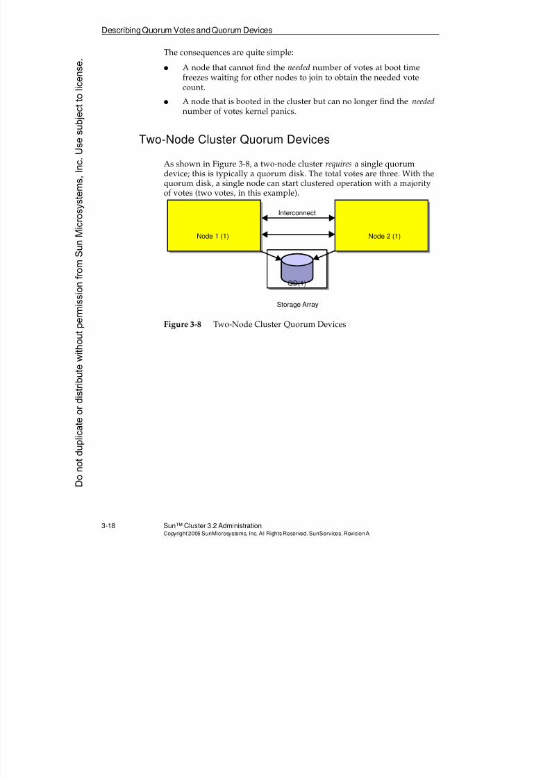
8/4/2019 Sun Cluster 3.2 Administration VC-ES-345
http://slidepdf.com/reader/full/sun-cluster-32-administration-vc-es-345 116/585
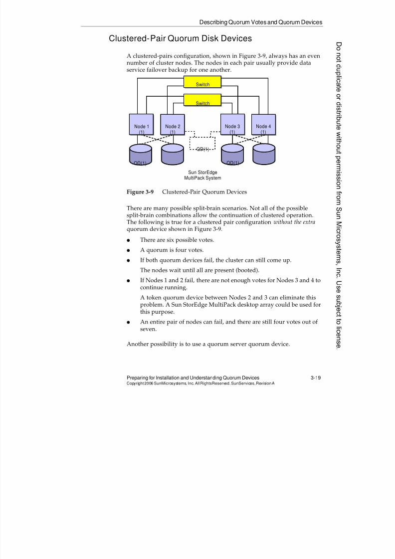
8/4/2019 Sun Cluster 3.2 Administration VC-ES-345
http://slidepdf.com/reader/full/sun-cluster-32-administration-vc-es-345 117/585
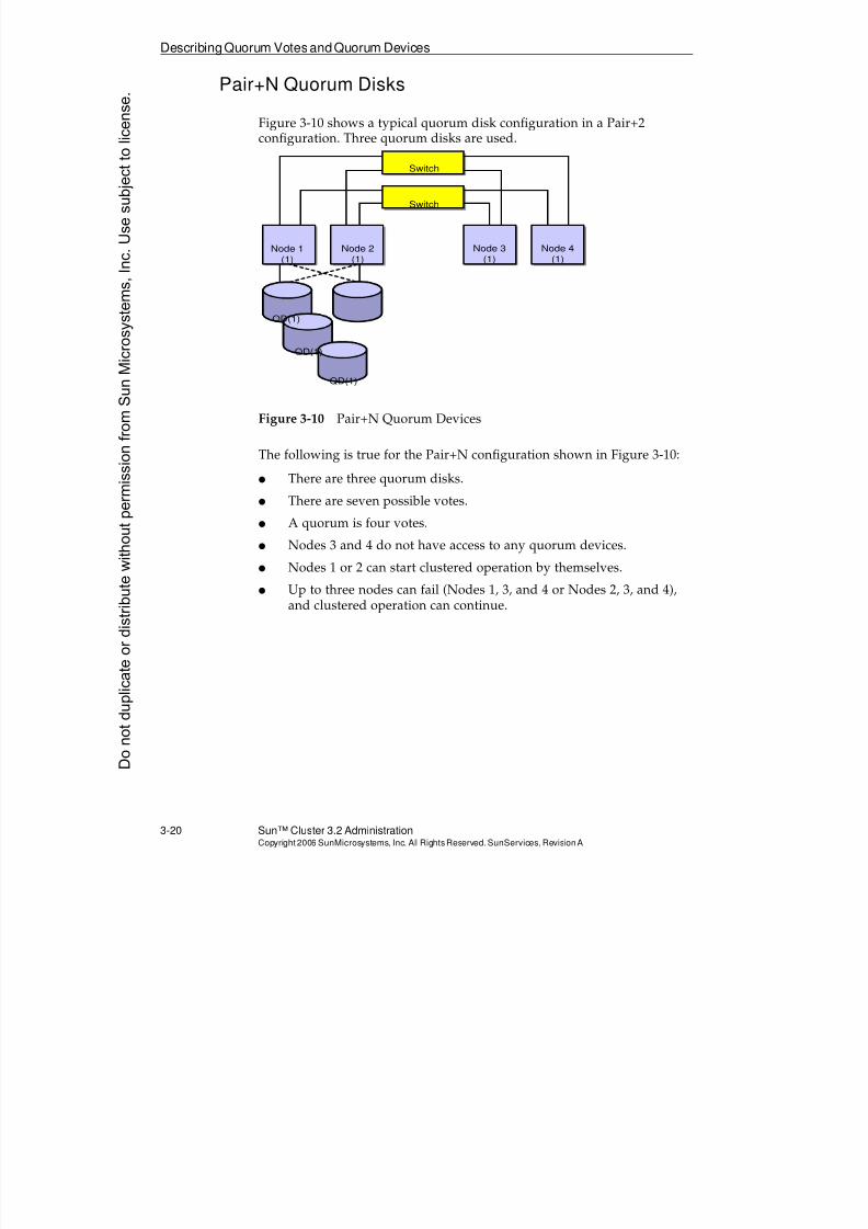
8/4/2019 Sun Cluster 3.2 Administration VC-ES-345
http://slidepdf.com/reader/full/sun-cluster-32-administration-vc-es-345 118/585
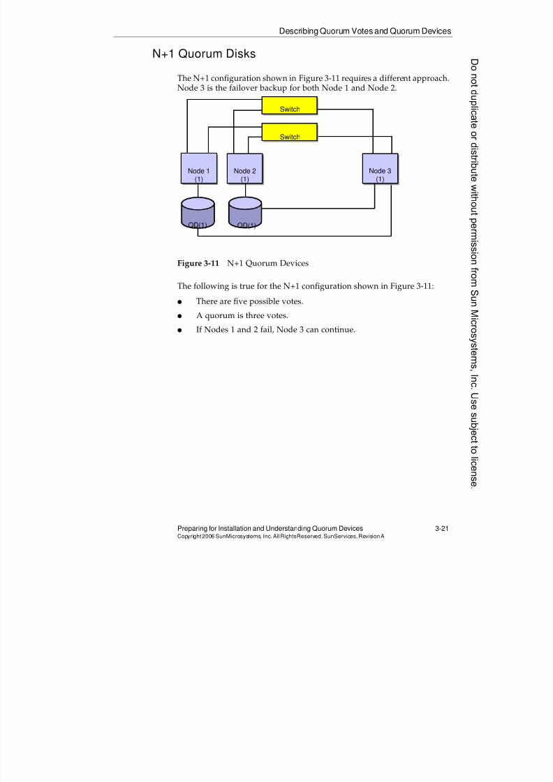
8/4/2019 Sun Cluster 3.2 Administration VC-ES-345
http://slidepdf.com/reader/full/sun-cluster-32-administration-vc-es-345 119/585
Describing Quorum Votes and Quorum Devices
Preparing for Installation and Understanding Quorum Devices 3-21Copyright2006 SunMicrosystems, Inc. AllRightsReserved. SunServices,RevisionA
N+1 Quorum Disks
The N+1 configuration shown in Figure 3-11 requires a different approach.Node 3 is the failover backup for both Node 1 and Node 2.
Figure 3-11 N+1 Quorum Devices
The following is true for the N+1 configuration shown in Figure 3-11:
q There are five possible votes.
q A quorum is three votes.q If Nodes 1 and 2 fail, Node 3 can continue.
Switch
Switch
Node 1(1)
Node 2(1)
Node 3(1)
QD(1)QD(1)
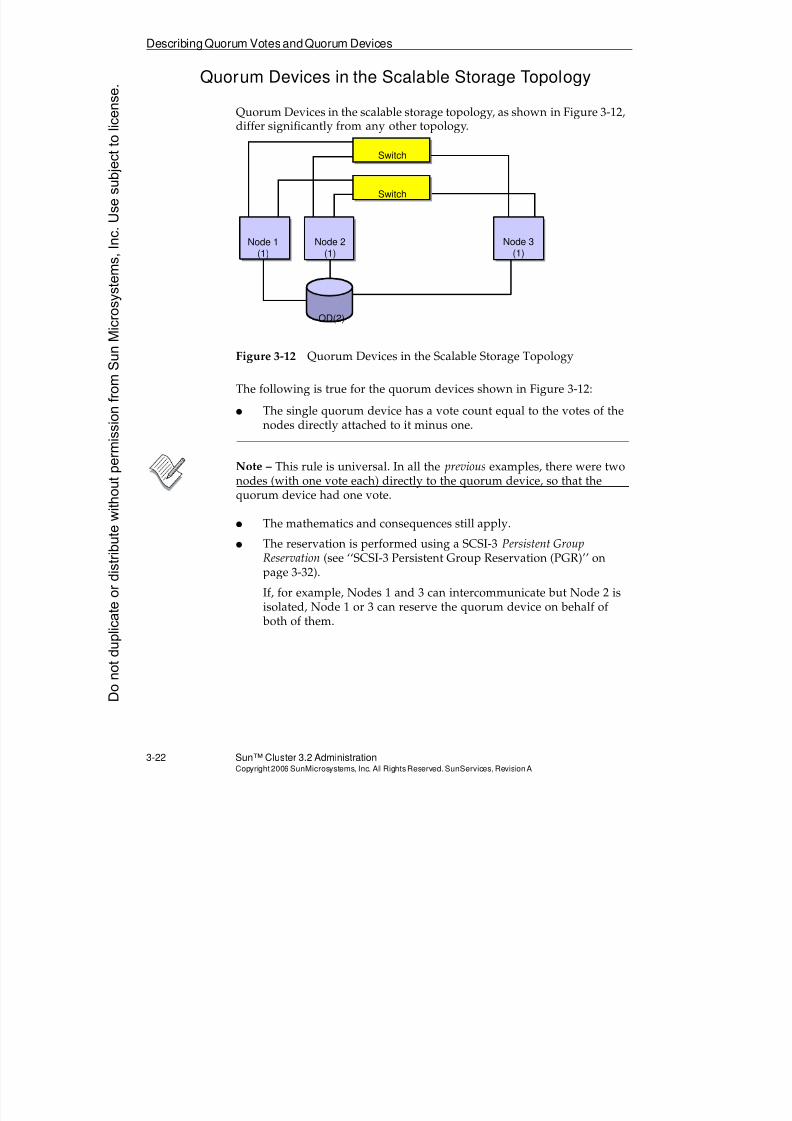
8/4/2019 Sun Cluster 3.2 Administration VC-ES-345
http://slidepdf.com/reader/full/sun-cluster-32-administration-vc-es-345 120/585
DescribingQuorum VotesandQuorum Devices
3-22 Sun™ Cluster 3.2 AdministrationCopyright2006 SunMicrosystems, Inc. AllRights Reserved.SunServices,RevisionA
Quorum Devices in the Scalable Storage Topology
Quorum Devices in the scalable storage topology, as shown in Figure 3-12,differ significantly from any other topology.
Figure 3-12 Quorum Devices in the Scalable Storage Topology
The following is true for the quorum devices shown in Figure 3-12:
q The single quorum device has a vote count equal to the votes of thenodes directly attached to it minus one.
Note – This rule is universal. In all the previous examples, there were twonodes (with one vote each) directly to the quorum device, so that thequorum device had one vote.
q The mathematics and consequences still apply.
q The reservation is performed using a SCSI-3 Persistent GroupReservation (see ‘‘SCSI-3 Persistent Group Reservation (PGR)’’ onpage 3-32).
If, for example, Nodes 1 and 3 can intercommunicate but Node 2 is
isolated, Node 1 or 3 can reserve the quorum device on behalf of both of them.
Switch
Switch
Node 1(1)
Node 2(1)
Node 3(1)
QD(2)
Donotduplicate
ordistributewithoutpermissionfrom SunMicrosystems,Inc.Usesubject
tolicense.
8/4/2019 Sun Cluster 3.2 Administration VC-ES-345
http://slidepdf.com/reader/full/sun-cluster-32-administration-vc-es-345 121/585
Describing Quorum Votes and Quorum Devices
Preparing for Installation and Understanding Quorum Devices 3-23Copyright2006 SunMicrosystems, Inc. AllRightsReserved. SunServices,RevisionA
Note – It would seem that in the same race, Node 2 could win andeliminate both Nodes 2 and 3. ‘‘Intentional Reservation Delays forPartitions With Fewer Than Half of the Nodes’’ on page 3-34 shows whythis is unlikely.
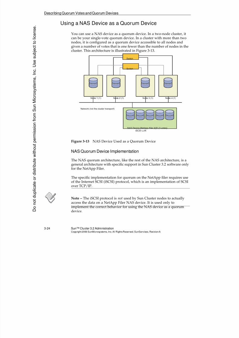
8/4/2019 Sun Cluster 3.2 Administration VC-ES-345
http://slidepdf.com/reader/full/sun-cluster-32-administration-vc-es-345 122/585
DescribingQuorum VotesandQuorum Devices
3-24 Sun™ Cluster 3.2 AdministrationCopyright2006 SunMicrosystems, Inc. AllRights Reserved.SunServices,RevisionA
Using a NAS Device as a Quorum Device
You can use a NAS device as a quorum device. In a two-node cluster, itcan be your single-vote quorum device. In a cluster with more than twonodes, it is configured as a quorum device accessible to all nodes and
given a number of votes that is one fewer than the number of nodes in thecluster. This architecture is illustrated in Figure 3-13.
Figure 3-13 NAS Device Used as a Quorum Device
NAS Quorum Device Implementation
The NAS quorum architecture, like the rest of the NAS architecture, is ageneral architecture with specific support in Sun Cluster 3.2 software onlyfor the NetApp Filer.
The specific implementation for quorum on the NetApp filer requires use
of the Internet SCSI (iSCSI) protocol, which is an implementation of SCSIover TCP/IP.
Note – The iSCSI protocol is not used by Sun Cluster nodes to actuallyaccess the data on a NetApp Filer NAS device. It is used only toimplement the correct behavior for using the NAS device as a quorumdevice.
Network (not the cluster transport)
Node 1 (1) Node 2 (1) Node 3 (1) Node 4 (1)
Switch
Switch
NAS Device (NetApp Filer QD (3 votes)iSCSI LUN
)
Donotduplicate
ordistributewithoutpermissionfrom SunMicrosystems,Inc.Usesubject
tolicense.
8/4/2019 Sun Cluster 3.2 Administration VC-ES-345
http://slidepdf.com/reader/full/sun-cluster-32-administration-vc-es-345 123/585
Describing Quorum Votes and Quorum Devices
Preparing for Installation and Understanding Quorum Devices 3-25Copyright2006 SunMicrosystems, Inc. AllRightsReserved. SunServices,RevisionA
On the NetApp Filer side, the requirements for operation as a Sun Clusterquorum device are as follows:
q You must install the iSCSI license from your NAS device vendor.
q You must configure an iSCSI Logical Unit (LUN) for use as the
quorum device.q When booting the cluster, you must always boot the NAS device
before you boot the cluster nodes.
On the cluster side, the requirements and restrictions are as follows:
q The iSCSI functionality is built into the NTAPclnas package thatmust be installed on each cluster node.
q A cluster can use a NAS device for only a single quorum device.There should be no need for other quorum devices. This is true because, in a cluster of more than two nodes, the quorum acts like aSCSI-3 quorum device attached to all the nodes.
q Multiple clusters using the same NAS device can use separate iSCSILUN’s on that device as their quorum devices.
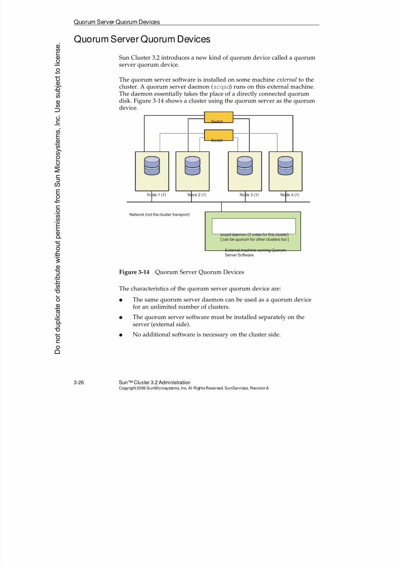
8/4/2019 Sun Cluster 3.2 Administration VC-ES-345
http://slidepdf.com/reader/full/sun-cluster-32-administration-vc-es-345 124/585
Quorum Server Quorum Devices
3-26 Sun™ Cluster 3.2 AdministrationCopyright2006 SunMicrosystems, Inc. AllRights Reserved.SunServices,RevisionA
Quorum Server Quorum Devices
Sun Cluster 3.2 introduces a new kind of quorum device called a quorumserver quorum device.
The quorum server software is installed on some machine external to thecluster. A quorum server daemon (scqsd) runs on this external machine.The daemon essentially takes the place of a directly connected quorumdisk. Figure 3-14 shows a cluster using the quorum server as the quorumdevice.
Figure 3-14 Quorum Server Quorum Devices
The characteristics of the quorum server quorum device are:
q The same quorum server daemon can be used as a quorum device
for an unlimited number of clusters.
q The quorum server software must be installed separately on theserver (external side).
q No additional software is necessary on the cluster side.
Network (not the cluster transport)
Node 1 (1) Node 2 (1) Node 3 (1) Node 4 (1)
Switch
Switch
External machine running QuorumServer Software
scqsd daemon (3 votes for this cluster)[ can be quorum for other clusters too ]
Donotduplicate
ordistributewithoutpermissionfrom SunMicrosystems,Inc.Usesubject
tolicense.
8/4/2019 Sun Cluster 3.2 Administration VC-ES-345
http://slidepdf.com/reader/full/sun-cluster-32-administration-vc-es-345 125/585
Quorum Server Quorum Devices
Preparing for Installation and Understanding Quorum Devices 3-27Copyright2006 SunMicrosystems, Inc. AllRightsReserved. SunServices,RevisionA
q A quorum server is especially useful when there is a great physicaldistance between quorum nodes. It would be an ideal solution for acluster using the data replication topology.
q Quorum server can be used on any cluster where you prefer thelogic of having a single cluster quorum device with quorum device
votes automatically assigned to be one fewer than the node votes.
For example, with a clustered pairs topology, you might prefer thesimplicity of a quorum server quorum device. In that example, anysingle node could boot into the cluster by itself, if it could access thequorum server. Of course, you might not be able to run clusteredapplications unless the storage for a particular application is alsoavailable, but those relationships can be controlled properly by theapplication resource dependencies that we will learn about inModule 9.
8/4/2019 Sun Cluster 3.2 Administration VC-ES-345
http://slidepdf.com/reader/full/sun-cluster-32-administration-vc-es-345 126/585
Preventing Cluster Amnesia With Persistent Reservations
3-28 Sun™ Cluster 3.2 AdministrationCopyright2006 SunMicrosystems, Inc. AllRights Reserved.SunServices,RevisionA
Preventing Cluster Amnesia With Persistent Reservations
Quorum devices in the Sun Cluster software environment are used notonly as a means of failure fencing but also as a means to prevent clusteramnesia.
Earlier you reviewed the following scenario:
1. In a two-node cluster (Node 1 and Node 2), Node 2 is halted formaintenance.
2. Meanwhile Node 1, running fine in the cluster, makes all sorts ofcluster configuration changes (new device groups, resource groups).
3. Now Node 1 is shut down.
4. You try to boot Node 2 to form a new cluster.
In this simple scenario, the problem is that if you were allowed to bootNode 2 at the end, it would not have the correct copy of the CCR. Node 2would have to use the copy that it has (because there is no other copyavailable) and you would lose the changes to the cluster configurationmade in Step 2.
The Sun Cluster software quorum involves persistent reservations thatprevent Node 2 from booting into the cluster. It is not able to count thequorum device as a vote. Therefore, Node 2 waits until the other node boots to achieve the correct number of quorum votes.
Donotduplicate
ordistributewithoutpermissionfrom SunMicrosystems,Inc.Usesubject
tolicense.
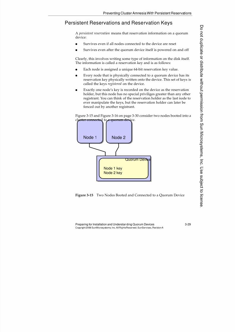
8/4/2019 Sun Cluster 3.2 Administration VC-ES-345
http://slidepdf.com/reader/full/sun-cluster-32-administration-vc-es-345 127/585
Preventing Cluster Amnesia With Persistent Reservations
Preparing for Installation and Understanding Quorum Devices 3-29Copyright2006 SunMicrosystems, Inc. AllRightsReserved. SunServices,RevisionA
Persistent Reservations and Reservation Keys
A persistent reservation means that reservation information on a quorumdevice:
q Survives even if all nodes connected to the device are resetq Survives even after the quorum device itself is powered on and off
Clearly, this involves writing some type of information on the disk itself.The information is called a reservation key and is as follows:
q Each node is assigned a unique 64-bit reservation key value.
q Every node that is physically connected to a quorum device has itsreservation key physically written onto the device. This set of keys iscalled the keys registered on the device.
q Exactly one node’s key is recorded on the device as the reservationholder, but this node has no special priviliges greater than any otherregistrant. You can think of the reservation holder as the last node toever manipulate the keys, but the reservation holder can later befenced out by another registrant.
Figure 3-15 and Figure 3-16 on page 3-30 consider two nodes booted into acluster connected to a quorum device.
Figure 3-15 Two Nodes Booted and Connected to a Quorum Device
Node 1 Node 2
Quorum Device
Node 1 key
Node 2 key
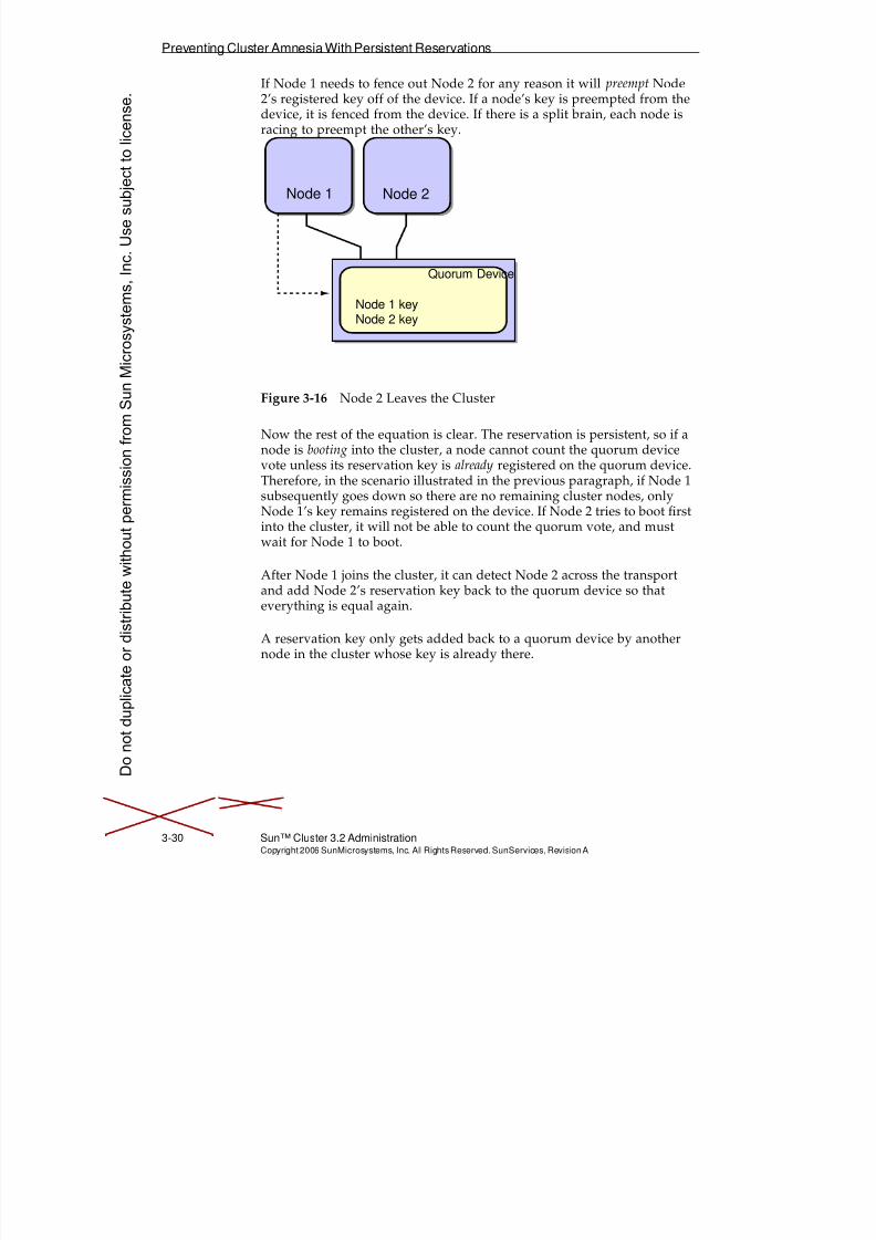
8/4/2019 Sun Cluster 3.2 Administration VC-ES-345
http://slidepdf.com/reader/full/sun-cluster-32-administration-vc-es-345 128/585
Preventing Cluster Amnesia With Persistent Reservations
3-30 Sun™ Cluster 3.2 AdministrationCopyright2006 SunMicrosystems, Inc. AllRights Reserved.SunServices,RevisionA
If Node 1 needs to fence out Node 2 for any reason it will preempt Node2’s registered key off of the device. If a node’s key is preempted from thedevice, it is fenced from the device. If there is a split brain, each node isracing to preempt the other’s key.
Figure 3-16 Node 2 Leaves the Cluster
Now the rest of the equation is clear. The reservation is persistent, so if anode is booting into the cluster, a node cannot count the quorum devicevote unless its reservation key is already registered on the quorum device.Therefore, in the scenario illustrated in the previous paragraph, if Node 1
subsequently goes down so there are no remaining cluster nodes, onlyNode 1’s key remains registered on the device. If Node 2 tries to boot firstinto the cluster, it will not be able to count the quorum vote, and mustwait for Node 1 to boot.
After Node 1 joins the cluster, it can detect Node 2 across the transportand add Node 2’s reservation key back to the quorum device so thateverything is equal again.
A reservation key only gets added back to a quorum device by anothernode in the cluster whose key is already there.
Node 1 Node 2
Quorum Device
Node 1 keyNode 2 key
Donotduplicate
ordistributewithoutpermissionfrom SunMicrosystems,Inc.Usesubject
tolicense.
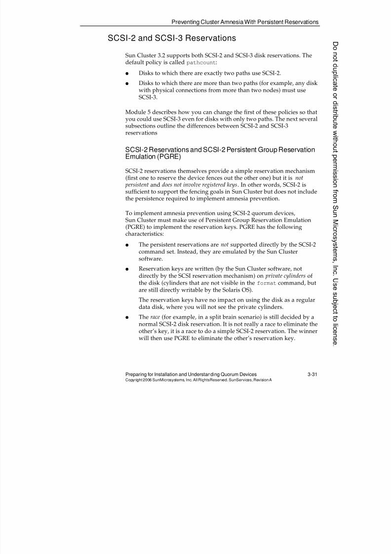
8/4/2019 Sun Cluster 3.2 Administration VC-ES-345
http://slidepdf.com/reader/full/sun-cluster-32-administration-vc-es-345 129/585
Preventing Cluster Amnesia With Persistent Reservations
Preparing for Installation and Understanding Quorum Devices 3-31Copyright2006 SunMicrosystems, Inc. AllRightsReserved. SunServices,RevisionA
SCSI-2 and SCSI-3 Reservations
Sun Cluster 3.2 supports both SCSI-2 and SCSI-3 disk reservations. Thedefault policy is called pathcount:
q Disks to which there are exactly two paths use SCSI-2.q Disks to which there are more than two paths (for example, any disk
with physical connections from more than two nodes) must useSCSI-3.
Module 5 describes how you can change the first of these policies so thatyou could use SCSI-3 even for disks with only two paths. The next severalsubsections outline the differences between SCSI-2 and SCSI-3reservations
SCSI-2 Reservations and SCSI-2 Persistent Group ReservationEmulation (PGRE)
SCSI-2 reservations themselves provide a simple reservation mechanism(first one to reserve the device fences out the other one) but it is not persistent and does not involve registered keys. In other words, SCSI-2 issufficient to support the fencing goals in Sun Cluster but does not includethe persistence required to implement amnesia prevention.
To implement amnesia prevention using SCSI-2 quorum devices,Sun Cluster must make use of Persistent Group Reservation Emulation(PGRE) to implement the reservation keys. PGRE has the followingcharacteristics:
q The persistent reservations are not supported directly by the SCSI-2command set. Instead, they are emulated by the Sun Clustersoftware.
q Reservation keys are written (by the Sun Cluster software, notdirectly by the SCSI reservation mechanism) on private cylinders ofthe disk (cylinders that are not visible in the format command, butare still directly writable by the Solaris OS).
The reservation keys have no impact on using the disk as a regulardata disk, where you will not see the private cylinders.
q The race (for example, in a split brain scenario) is still decided by anormal SCSI-2 disk reservation. It is not really a race to eliminate theother’s key, it is a race to do a simple SCSI-2 reservation. The winnerwill then use PGRE to eliminate the other’s reservation key.
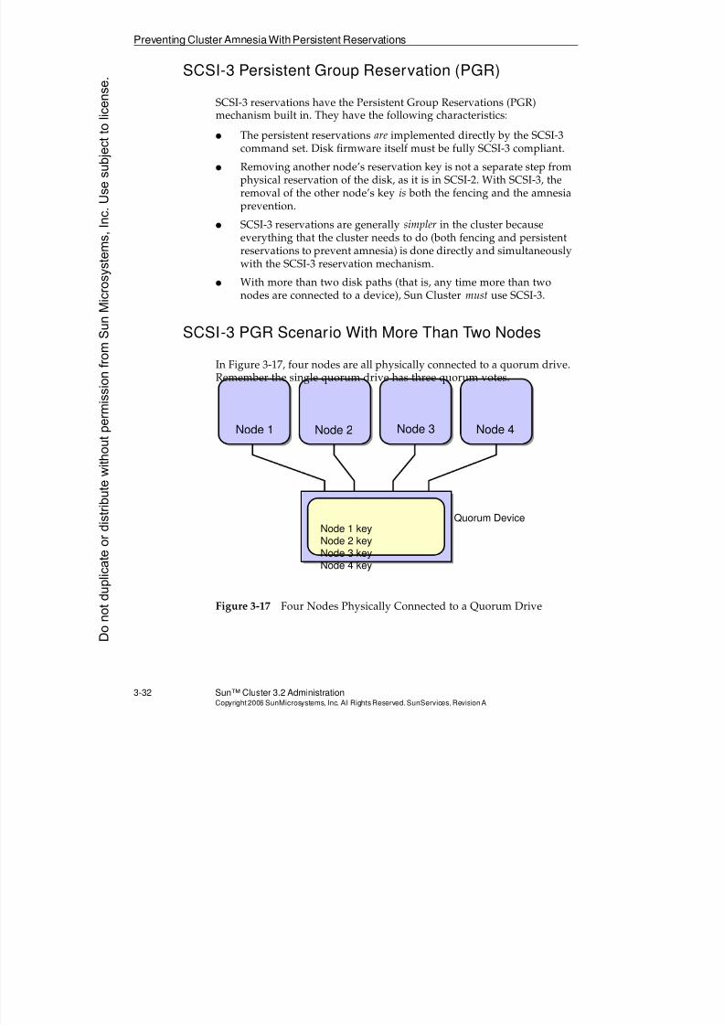
8/4/2019 Sun Cluster 3.2 Administration VC-ES-345
http://slidepdf.com/reader/full/sun-cluster-32-administration-vc-es-345 130/585
8/4/2019 Sun Cluster 3.2 Administration VC-ES-345
http://slidepdf.com/reader/full/sun-cluster-32-administration-vc-es-345 131/585
Preventing Cluster Amnesia With Persistent Reservations
Preparing for Installation and Understanding Quorum Devices 3-33Copyright2006 SunMicrosystems, Inc. AllRightsReserved. SunServices,RevisionA
Now imagine that because of multiple transport failures there is apartitioning where Nodes 1 and 3 can see each other over the transportand Nodes 2 and 4 can see each other over the transport.
In each pair, the node with the lower reservation key tries to eliminate the
registered reservation key of the other pair. The SCSI-3 protocol assuresthat only one pair will remain registered (the operation is atomic). This isshown in Figure 3-18.
Figure 3-18 One Pair of Nodes Eliminating the Other
In the diagram, Node 1 has successfully won the race to eliminate thekeys for Nodes 2 and 4. Because Nodes 2 and 4 have their reservation keyeliminated, they cannot count the three votes of the quorum device.Because they fall below the needed quorum, they will kernel panic.
Cluster amnesia is avoided in the same way as in a two-node quorumdevice. If you now shut down the whole cluster, Node 2 and Node 4cannot count the quorum device because their reservation key iseliminated. They would have to wait for either Node 1 or Node 3 to join.One of those nodes can then add back reservation keys for Node 2 andNode 4.
Node 1 Node 2 Node 3 Node 4
Quorum Device
(3 votes)Node 1 key
Node 2 keyNode 3 keyNode 4 key
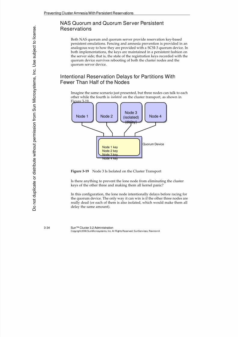
8/4/2019 Sun Cluster 3.2 Administration VC-ES-345
http://slidepdf.com/reader/full/sun-cluster-32-administration-vc-es-345 132/585
8/4/2019 Sun Cluster 3.2 Administration VC-ES-345
http://slidepdf.com/reader/full/sun-cluster-32-administration-vc-es-345 133/585
8/4/2019 Sun Cluster 3.2 Administration VC-ES-345
http://slidepdf.com/reader/full/sun-cluster-32-administration-vc-es-345 134/585
DataFencing
3-36 Sun™ Cluster 3.2 AdministrationCopyright2006 SunMicrosystems, Inc. AllRights Reserved.SunServices,RevisionA
Data Fencing
As an extra precaution, nodes that are eliminated from the cluster becauseof quorum problems also lose access to all shared data devices.
The reason for this is to eliminate a potential timing problem. The node ornodes that remain in the cluster have no idea whether the nodes beingeliminated from the cluster are actually still running. If they are running,they will have a kernel panic (after they recognize that they have fallen beneath the required quorum votes). However, the surviving node ornodes cannot wait for the other nodes to kernel panic before taking overthe data. The reason nodes are being eliminated is that there has been acommunication failure with them.
To eliminate this potential timing problem, which could otherwise lead to
data corruption, before a surviving node or nodes reconfigures the dataand applications, it fences the eliminated node or nodes from all shareddata devices, in the following manner:
q With the default pathcount policy, SCSI-2 reservation is used fortwo-path devices and SCSI-3 for devices with more than two paths.
q You can change the policy to use SCSI-3 even if there are only twopaths (see Module 5).
q If you do use the default SCSI-2 for a two-path device, data fencing is just the reservation and does not include any PGRE.
q For NetApp Filer NAS devices, a surviving node informs the NASdevice to eliminate the NFS share from the eliminated node ornodes.
Data fencing is released when a fenced node is able to boot successfullyinto the cluster again.
Note – This data fencing is the reason you absolutely can not put any bootdevice in a shared storage array. If you do so, a node that is eliminated fromthe cluster is fenced off from its own boot device.
Donotduplicate
ordistributewithoutpermissionfrom SunMicrosystems,Inc.Usesubject
tolicense.
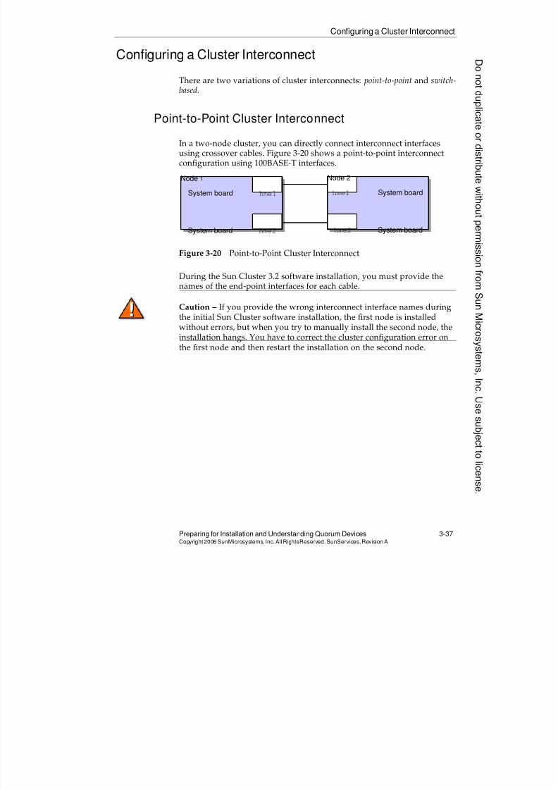
8/4/2019 Sun Cluster 3.2 Administration VC-ES-345
http://slidepdf.com/reader/full/sun-cluster-32-administration-vc-es-345 135/585
Configuring a Cluster Interconnect
Preparing for Installation and Understanding Quorum Devices 3-37Copyright2006 SunMicrosystems, Inc. AllRightsReserved. SunServices,RevisionA
Configuring a Cluster Interconnect
There are two variations of cluster interconnects: point-to-point and switch-based.
Point-to-Point Cluster Interconnect
In a two-node cluster, you can directly connect interconnect interfacesusing crossover cables. Figure 3-20 shows a point-to-point interconnectconfiguration using 100BASE-T interfaces.
Figure 3-20 Point-to-Point Cluster Interconnect
During the Sun Cluster 3.2 software installation, you must provide thenames of the end-point interfaces for each cable.
Caution – If you provide the wrong interconnect interface names during
the initial Sun Cluster software installation, the first node is installedwithout errors, but when you try to manually install the second node, theinstallation hangs. You have to correct the cluster configuration error onthe first node and then restart the installation on the second node.
System board hme1
System board hme2
hme1 System board
hme2 System board
Node 1 Node 2
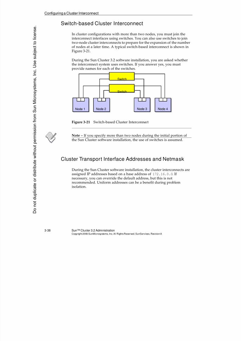
8/4/2019 Sun Cluster 3.2 Administration VC-ES-345
http://slidepdf.com/reader/full/sun-cluster-32-administration-vc-es-345 136/585
Configuring a Cluster Interconnect
3-38 Sun™ Cluster 3.2 AdministrationCopyright2006 SunMicrosystems, Inc. AllRights Reserved.SunServices,RevisionA
Switch-based Cluster Interconnect
In cluster configurations with more than two nodes, you must join theinterconnect interfaces using switches. You can also use switches to jointwo-node cluster interconnects to prepare for the expansion of the number
of nodes at a later time. A typical switch-based interconnect is shown inFigure 3-21.
During the Sun Cluster 3.2 software installation, you are asked whetherthe interconnect system uses switches. If you answer yes, you mustprovide names for each of the switches.
Figure 3-21 Switch-based Cluster Interconnect
Note – If you specify more than two nodes during the initial portion ofthe Sun Cluster software installation, the use of switches is assumed.
Cluster Transport Interface Addresses and Netmask
During the Sun Cluster software installation, the cluster interconnects areassigned IP addresses based on a base address of 172.16.0.0. Ifnecessary, you can override the default address, but this is not
recommended. Uniform addresses can be a benefit during problemisolation.
Switch
Switch
Node 1 Node 2 Node 3 Node 4
Donotduplicate
ordistributewithoutpermissionfrom SunMicrosystems,Inc.Usesubject
tolicense.
8/4/2019 Sun Cluster 3.2 Administration VC-ES-345
http://slidepdf.com/reader/full/sun-cluster-32-administration-vc-es-345 137/585
Configuring a Cluster Interconnect
Preparing for Installation and Understanding Quorum Devices 3-39Copyright2006 SunMicrosystems, Inc. AllRightsReserved. SunServices,RevisionA
The netmask property associated with the entire cluster transportdescribes, together with the base address, the entire range of addressesassociated with the transport. For example, if you used the default baseaddress of 172.16.0.0 and the default netmask of 255.255.248.0, youwould be dedicating an 11-bit range (255.255.248.0 has 11 0’s at the
end) to the cluster transport. This range is172.16.0.0
–172.16.7.255
.
Note – When you set 255.255.248.0 as the cluster transport netmaskyou will not see this netmask actually applied to any of the privatenetwork adapters. Once again, the cluster uses this netmask to define theentire range it has access to, and then subdivides the range even further tocover the multiple separate networks that make up the cluster transport.
Choosing the Cluster Transport Netmask Based onAnticipated Nodes and Private Subnets
While you can choose the cluster transport netmask by hand, the clusterprefers instead that you specify:
q The maximum anticipated number of private networks
q The maximum anticipated number of nodes
The Sun Cluster software uses a formula to derive a suggested netmask.
Sun Cluster’s actual needs are:
q Physical subnets (the subnets for the actual private network switchesor crossover cables) with a capacity of the actual number of nodes,plus the all zeros and all ones addresses.
If you say your anticipated maximum is eight nodes, Sun Clusterneeds to use subnets that have four bits (not three) for the host part because you need to allow for the all zeros and all ones addresses.
q A single additional virtual subnet corresponding to the addresses onthe clprivnet0 adapters. This needs more capacity than just the
number of nodes because you can actually choose to give non-globalzones their own IP addresses on this network as well.
When you say you want P physical private network subnets, the clusteruses a conservative formula (4/3)*(P + 2) subnets to calculate theanticipated space it needs for subnetting (including the wider clprivnet0subnet). This should just be considered a conservative formula.
8/4/2019 Sun Cluster 3.2 Administration VC-ES-345
http://slidepdf.com/reader/full/sun-cluster-32-administration-vc-es-345 138/585
Configuring a Cluster Interconnect
3-40 Sun™ Cluster 3.2 AdministrationCopyright2006 SunMicrosystems, Inc. AllRights Reserved.SunServices,RevisionA
For example, if you say your absolute maximum is eight nodes and fourphysical subnets, Sun Cluster will calculate:
q Four bits required for the host part for actual physical subnets (asabove).
q
Three bits required for subnetting (apply the formula (4/3)* (4+2)and you get eight subnets, for which there are three bits required.
q The total bits is 4+3 or a total of seven bits of private network space.So the suggested netmask will have seven bits of zeros, which is255.255.255.128.
Note – In Sun Cluster 3.2, if you want to restrict private networkaddresses with a class C-like space, similar to 192.168.5.0, you can do iteasily even with relatively large numbers of nodes and subnets. In theabove example, you could support eight nodes and as many as fourprivate networks all in the space 192,168.5.0 - 192.168.5.127.
Donotduplicate
ordistributewithoutpermissionfrom SunMicrosystems,Inc.Usesubject
tolicense.
8/4/2019 Sun Cluster 3.2 Administration VC-ES-345
http://slidepdf.com/reader/full/sun-cluster-32-administration-vc-es-345 139/585
8/4/2019 Sun Cluster 3.2 Administration VC-ES-345
http://slidepdf.com/reader/full/sun-cluster-32-administration-vc-es-345 140/585
Configuring a Cluster Interconnect
3-42 Sun™ Cluster 3.2 AdministrationCopyright2006 SunMicrosystems, Inc. AllRights Reserved.SunServices,RevisionA
4. Make sure that the interface you are looking at is not actually on thepublic net:
a. In one window run the snoop command for the interface inquestion:
# ifconfig qfe1 plumb
# snoop -d qfe1
hope to see no output here
b. In another window, ping the public broadcast address, andmake sure no traffic is seen by the candidate interface.
# ping public_net_broadcast_address
If you do see snoop output, you are looking at a public networkadapter. Do not continue. Just return to step 3 and pick a newcandidate.
5. Now that you know your adapter is not on the public net, check to
see if it is connected on a private net. Make up some unused subnetaddress just to test out interconnectivity across a private network. Donot use addresses in the existing public subnet space.
# ifconfig qfe1 192.168.1.1 up
6. Perform Steps 4 and 5 to try to guess the “matching candidate” onthe other node. Choose a corresponding IP address, for example192.168.1.2.
7. Test that the nodes can ping across each private network, forexample:
# ping 192.168.1.2192.168.1.2 is alive
8. After you have identified the new network interfaces, bring themdown again. Cluster installation fails if your transport networkinterfaces are still up from testing.
# ifconfig qfe1 down unplumb
9. Repeat Steps 3 through 8 with transport adapter candidates for thesecond cluster transport. Repeat again if you are configuring morethan two cluster transports.
Donotduplicate
ordistributewithoutpermissionfrom SunMicrosystems,Inc.Usesubject
tolicense.
8/4/2019 Sun Cluster 3.2 Administration VC-ES-345
http://slidepdf.com/reader/full/sun-cluster-32-administration-vc-es-345 141/585
Identifying Public Network Adapters
Preparing for Installation and Understanding Quorum Devices 3-43Copyright2006 SunMicrosystems, Inc. AllRightsReserved. SunServices,RevisionA
Identifying Public Network Adapters
You will not be asked about public network configuration at the time youare installing the cluster.
The public network interfaces must be managed by IPMP, which can beadministered either before or after cluster installation. In this course, youwill do it after cluster installation in Module 8.
Because you are identifying your private transport interfaces beforecluster installation, it can be useful to identify your public networkinterfaces at the same time, so as to avoid confusion.
Your primary public network adapter should be the only one currentlyconfigured on the public network. You can verify this with the following
command:# ls -l /etc/hostname.*
# ifconfig -a
You can verify your secondary public network adapter, if applicable, by:
q Making sure it is not one of those you identified to be used as theprivate transport
q Making sure it can snoop public network broadcast traffic
# ifconfig ifname plumb
# snoop -d ifname(other window or node)# ping -s pubnet_broadcast_addr
8/4/2019 Sun Cluster 3.2 Administration VC-ES-345
http://slidepdf.com/reader/full/sun-cluster-32-administration-vc-es-345 142/585
Configuring Shared Physical Adapters
3-44 Sun™ Cluster 3.2 AdministrationCopyright2006 SunMicrosystems, Inc. AllRights Reserved.SunServices,RevisionA
Configuring Shared Physical Adapters
Recall that certain adapters are capable of participating in tagged VLANs,and can be used as both private and public network adapters assumingthat the switches are also capable of tagged VLANs. This allows bladearchitecture servers that have only two physical network adapters to beclustered.
Note – At the time of writing this course, only the Broadcom GigabitEthernet (bge) adapters and Cassini Ethernet (ce) adapters are capable ofserving as shared physical adapters.
An adapter that is participating in a tagged VLAN configuration isassigned an instance number 1000*(Vlan_identifer) +
physical_instance_number.
For example, if you have a physical adapter ce1, and it is participating ina tagged VLAN with ID 3 as its public network personality, and a taggedVLAN with ID 5 as its private network personality, then it will appear as if itwere two separate adapters ce3001 and ce5001.
Configuring the Public Network
To configure a shared adapter’s public network personality, all you haveto do is configure the adapter instance according to the mathematicalformula above. VLAN ID3 is going to be used for the public networkidentity of what would otherwise be ce1, therefore you configure theadapter instance ce3001 by creating a file /etc/hostname.ce3001. Wheninstance ce3001 is plumbed, the adapter driver understands that it isusing tagged VLAN ID 3 on physical instance number 1.
Allocating a Different VLAN ID for the Private Network
You should never configure the private network ID manually. Instead,you should perform the initial configuration using the scinstall utility.This procedure is documented in Module 4. All you need to do is ensurethat you have a different VLAN ID for the public and private networks.The scinstall utility automatically detects a tagged VLAN-capableadapter and queries for the private VLAN ID.
Donotduplicate
ordistributewithoutpermissionfrom SunMicrosystems,Inc.Usesubject
tolicense.
8/4/2019 Sun Cluster 3.2 Administration VC-ES-345
http://slidepdf.com/reader/full/sun-cluster-32-administration-vc-es-345 143/585
Exercise: Preparing for Installation
Preparing for Installation and Understanding Quorum Devices 3-45Copyright2006 SunMicrosystems, Inc. AllRightsReserved. SunServices,RevisionA
Exercise: Preparing for Installation
In this exercise, you complete the following tasks:
q Task 1 – Verifying the Solaris OS
q Task 2 – Identifying a Cluster Topology
q Task 3 – Selecting Quorum Devices
q Task 4 – Verifying the Cluster Interconnect Configuration
q Task 5 – Selecting Public Network Interfaces
Preparation
To begin this exercise, you must be connected to the cluster hosts through
the cconsole tool, and you should be logged into them as user root.
Note – During this exercise, when you see italicized variable names, suchas IPaddress , enclosure_name , node1 , or clustername embedded in acommand string, substitute the names appropriate for your cluster.
Task 1 – Verifying the Solaris OS
In this section, you verify that the boot disk is correctly partitioned on allnodes.
Perform the following steps:
1. Type the /etc/prtconf command on each node and record the sizeof physical memory (/etc/prtconf | grep Memory).
Node 1 memory: _______________
Node 2 memory: _______________
2. Type the df -kl command on each node, and verify that there is aglobaldevices file system mounted. The recommended size is512 Mbytes, which is sufficient for even huge numbers of devices.
3. Type swap -l on each node and verify that it has at least 750 Mbytesof swap space.
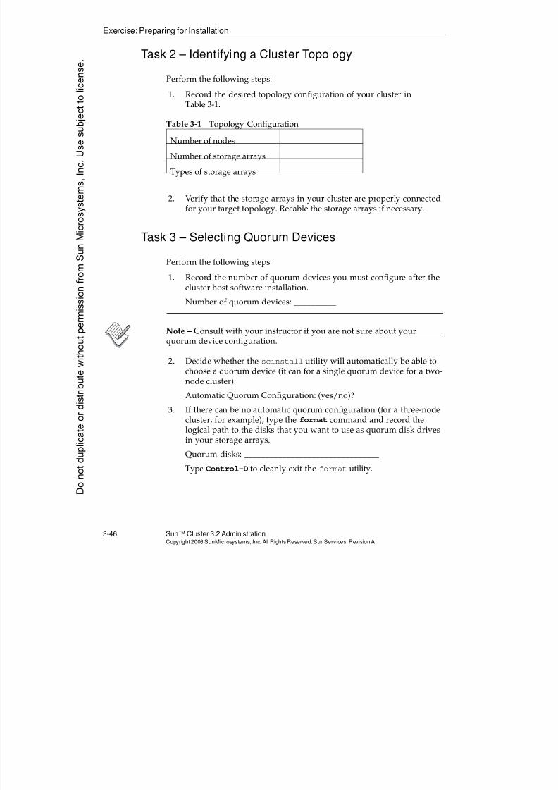
8/4/2019 Sun Cluster 3.2 Administration VC-ES-345
http://slidepdf.com/reader/full/sun-cluster-32-administration-vc-es-345 144/585
Exercise: Preparing for Installation
3-46 Sun™ Cluster 3.2 AdministrationCopyright2006 SunMicrosystems, Inc. AllRights Reserved.SunServices,RevisionA
Task 2 – Identifying a Cluster Topology
Perform the following steps:
1. Record the desired topology configuration of your cluster in
Table 3-1.
2. Verify that the storage arrays in your cluster are properly connectedfor your target topology. Recable the storage arrays if necessary.
Task 3 – Selecting Quorum Devices
Perform the following steps:
1. Record the number of quorum devices you must configure after thecluster host software installation.
Number of quorum devices: __________
Note – Consult with your instructor if you are not sure about yourquorum device configuration.
2. Decide whether the scinstall utility will automatically be able tochoose a quorum device (it can for a single quorum device for a two-node cluster).
Automatic Quorum Configuration: (yes/no)?
3. If there can be no automatic quorum configuration (for a three-nodecluster, for example), type the format command and record the
logical path to the disks that you want to use as quorum disk drivesin your storage arrays.
Quorum disks: ________________________________
Type Control-D to cleanly exit the format utility.
Table 3-1 Topology Configuration
Number of nodes
Number of storage arrays
Types of storage arrays
Donotduplicate
ordistributewithoutpermissionfrom SunMicrosystems,Inc.Usesubject
tolicense.
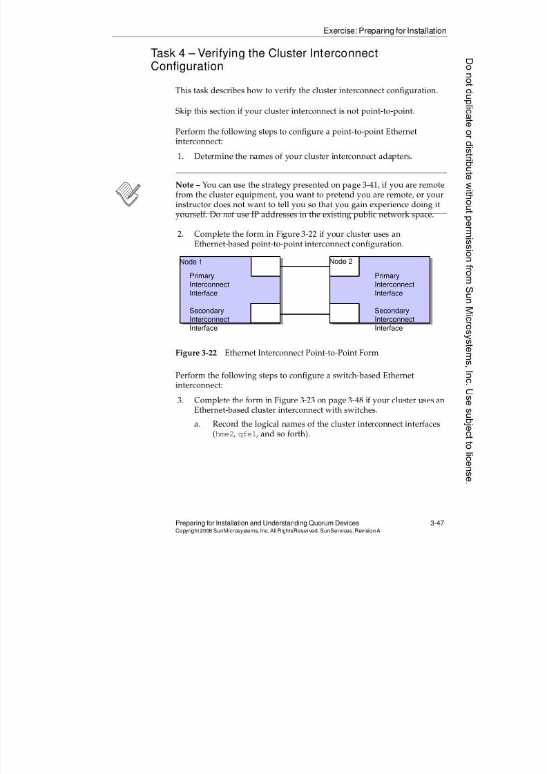
8/4/2019 Sun Cluster 3.2 Administration VC-ES-345
http://slidepdf.com/reader/full/sun-cluster-32-administration-vc-es-345 145/585
Exercise: Preparing for Installation
Preparing for Installation and Understanding Quorum Devices 3-47Copyright2006 SunMicrosystems, Inc. AllRightsReserved. SunServices,RevisionA
Task 4 – Verifying the Cluster InterconnectConfiguration
This task describes how to verify the cluster interconnect configuration.
Skip this section if your cluster interconnect is not point-to-point.
Perform the following steps to configure a point-to-point Ethernetinterconnect:
1. Determine the names of your cluster interconnect adapters.
Note – You can use the strategy presented on page 3-41, if you are remotefrom the cluster equipment, you want to pretend you are remote, or your
instructor does not want to tell you so that you gain experience doing ityourself. Do not use IP addresses in the existing public network space.
2. Complete the form in Figure 3-22 if your cluster uses anEthernet-based point-to-point interconnect configuration.
Figure 3-22 Ethernet Interconnect Point-to-Point Form
Perform the following steps to configure a switch-based Ethernetinterconnect:
3. Complete the form in Figure 3-23 on page 3-48 if your cluster uses anEthernet-based cluster interconnect with switches.
a. Record the logical names of the cluster interconnect interfaces(hme2, qfe1, and so forth).
PrimaryInterconnect
Interface
SecondaryInterconnect
Interface
PrimaryInterconnect
Interface
SecondaryInterconnect
Interface
Node 1 Node 2
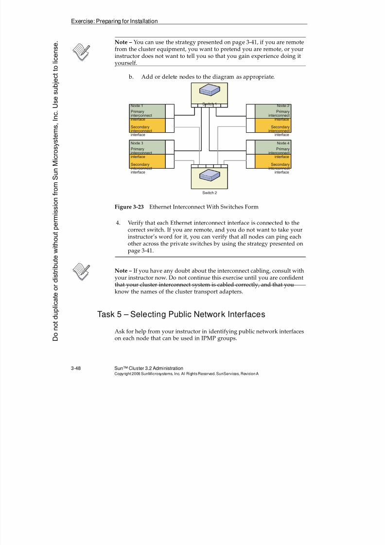
8/4/2019 Sun Cluster 3.2 Administration VC-ES-345
http://slidepdf.com/reader/full/sun-cluster-32-administration-vc-es-345 146/585
Exercise: Preparing for Installation
3-48 Sun™ Cluster 3.2 AdministrationCopyright2006 SunMicrosystems, Inc. AllRights Reserved.SunServices,RevisionA
Note – You can use the strategy presented on page 3-41, if you are remotefrom the cluster equipment, you want to pretend you are remote, or yourinstructor does not want to tell you so that you gain experience doing ityourself.
b. Add or delete nodes to the diagram as appropriate.
Figure 3-23 Ethernet Interconnect With Switches Form
4. Verify that each Ethernet interconnect interface is connected to thecorrect switch. If you are remote, and you do not want to take yourinstructor’s word for it, you can verify that all nodes can ping eachother across the private switches by using the strategy presented onpage 3-41.
Note – If you have any doubt about the interconnect cabling, consult withyour instructor now. Do not continue this exercise until you are confidentthat your cluster interconnect system is cabled correctly, and that you
know the names of the cluster transport adapters.
Task 5 – Selecting Public Network Interfaces
Ask for help from your instructor in identifying public network interfaceson each node that can be used in IPMP groups.
Switch 1
Switch 2
Node 1
Primaryinterconnectinterface
Secondaryinterconnectinterface
Node 3
Primaryinterconnectinterface
Secondaryinterconnectinterface
Node 2
Primaryinterconnect
interface
Secondaryinterconnect
interface
Node 4
Primaryinterconnect
interface
Secondaryinterconnect
interface
Donotduplicate
ordistributewithoutpermissionfrom SunMicrosystems,Inc.Usesubject
tolicense.
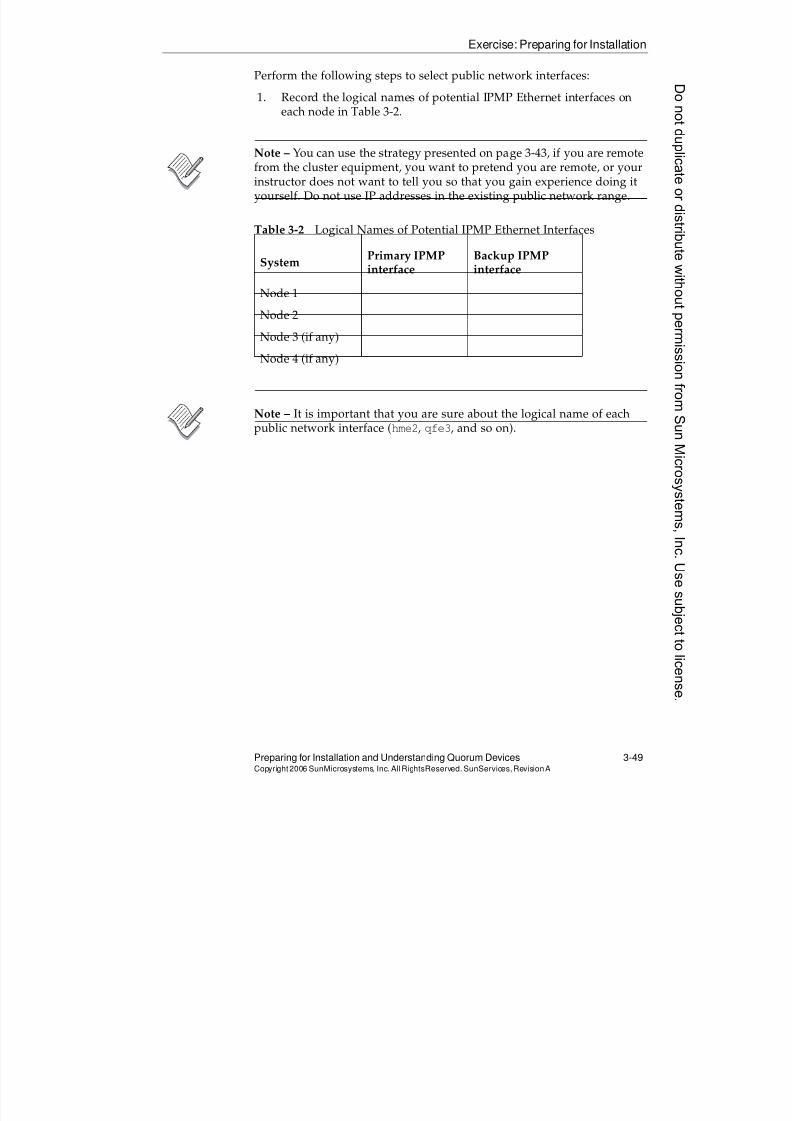
8/4/2019 Sun Cluster 3.2 Administration VC-ES-345
http://slidepdf.com/reader/full/sun-cluster-32-administration-vc-es-345 147/585
Exercise: Preparing for Installation
Preparing for Installation and Understanding Quorum Devices 3-49Copyright2006 SunMicrosystems, Inc. AllRightsReserved. SunServices,RevisionA
Perform the following steps to select public network interfaces:
1. Record the logical names of potential IPMP Ethernet interfaces oneach node in Table 3-2.
Note – You can use the strategy presented on page 3-43, if you are remotefrom the cluster equipment, you want to pretend you are remote, or yourinstructor does not want to tell you so that you gain experience doing ityourself. Do not use IP addresses in the existing public network range.
Note – It is important that you are sure about the logical name of eachpublic network interface (hme2, qfe3, and so on).
Table 3-2 Logical Names of Potential IPMP Ethernet Interfaces
System Primary IPMPinterface
Backup IPMPinterface
Node 1
Node 2
Node 3 (if any)
Node 4 (if any)

8/4/2019 Sun Cluster 3.2 Administration VC-ES-345
http://slidepdf.com/reader/full/sun-cluster-32-administration-vc-es-345 148/585
Exercise Summary
3-50 Sun™ Cluster 3.2 AdministrationCopyright2006 SunMicrosystems, Inc. AllRights Reserved.SunServices,RevisionA
Exercise Summary
?
!
Discussion – Take a few minutes to discuss what experiences, issues, ordiscoveries you had during the lab exercises.
q Experiences
q Interpretations
q Conclusions
q Applications
Donotduplicate
ordistributewithoutpermissionfrom SunMicrosystems,Inc.Usesubject
tolicense.
8/4/2019 Sun Cluster 3.2 Administration VC-ES-345
http://slidepdf.com/reader/full/sun-cluster-32-administration-vc-es-345 149/585
4-1Copyright2006 SunMicrosystems, Inc. AllRights Reserved.SunServices,RevisionA
Module 4
InstallingandConfiguringtheSunClusterSoftwareFramework
Objectives
Upon completion of this module, you should be able to:
q Understand the Sun Cluster installation and configuration steps
q Install the Sun Cluster packages using the Sun Java EnterpriseSystem (Java ES) installer
q Describe the Sun Cluster framework configuration
q Configure a cluster installation using all-at-once and typical modes
q Configure a cluster installation using one-at-a-time and custommodes
q Configure additional nodes for the one-at-a-time method
q Describe the Solaris OS files and settings that are automaticallyconfigured by scinstall
q Perform automatic quorum configuration
q Describe the manual quorum selection
q Perform post-installation configuration
8/4/2019 Sun Cluster 3.2 Administration VC-ES-345
http://slidepdf.com/reader/full/sun-cluster-32-administration-vc-es-345 150/585
Relevance
4-2 Sun™Cluster 3 .2AdministrationCopyright2006 SunMicrosystems, Inc. AllRights Reserved.SunServices,RevisionA
Relevance
?
!
Discussion – The following questions are relevant to understanding thecontent of this module:
q What advantages are we given by standardizing on the JavaEnterprise System (Java ES) installer as the utility to lay down thecluster packages?
q Why might you not want the configuration utilities to automaticallychoose a quorum device for you for a two-node cluster?
q Are there pieces of the cluster configuration you might need toconfigure manually after running the configuration utilityscinstall?
Donotduplicate
ordistributewithoutpermissionfrom SunMicrosystems,Inc.Usesubject
tolicense.
8/4/2019 Sun Cluster 3.2 Administration VC-ES-345
http://slidepdf.com/reader/full/sun-cluster-32-administration-vc-es-345 151/585
Additional Resources
Installing and Configuring the Sun Cluster Software Framework 4-3Copyright2006 SunMicrosystems, Inc. AllRightsReserved. SunServices,RevisionA
Additional Resources
Additional resources – The following references provide additional
information on the topics described in this module:q Sun Cluster System Administration Guide for Solaris OS, part number
819-2971.
q Sun Cluster Software Installation Guide for Solaris OS, part number 819-2970.
8/4/2019 Sun Cluster 3.2 Administration VC-ES-345
http://slidepdf.com/reader/full/sun-cluster-32-administration-vc-es-345 152/585
Sun Cluster Software Installation and Configuration
4-4 Sun™Cluster 3 .2AdministrationCopyright2006 SunMicrosystems, Inc. AllRights Reserved.SunServices,RevisionA
Sun Cluster Software Installation and Configuration
You must complete two distinct steps to successfully initialize theSun Cluster 3.2 framework and boot into the cluster:
1. Install the Sun Cluster 3.2 framework packages.2. Configure the Sun Cluster 3.2 software with scinstall.
It is required that these be done as separate steps, although both steps can be automated as part of Solaris jumpstart.
Introduction to Sun Cluster Package Installation
An initial (non-upgrade) installation of the Sun Cluster packages is
performed one of the following ways
q Using the Java ES installer utility that is always packaged with theSun Cluster framework (this can also be automated as part of a jumpstart install).
q Using a flash image that was created on a system where the SunCluster packages have been installed using the Java ES installer. Theflash image must have been created before the cluster was actuallyconfigured with scinstall.
Sun Cluster Packaging
You always install the Sun Cluster packages the same way despite the factthat Sun Cluster 3.2 may be bundled with either:
q The full collection of Java ES software (Sun Cluster, Java System WebServer, Messaging Server, Directory Server, and so on).
q A partial set of Java ES software, containing only availability-relatedproducts. This is called the Java ES Availability Suite.
The distribution comes either as:
q Two CD-ROMs, that combined make up the software distribution foreither SPARC or x86 versions
q A single DVD, containing the distribution for both SPARC and x86
Donotduplicate
ordistributewithoutpermissionfrom SunMicrosystems,Inc.Usesubject
tolicense.
8/4/2019 Sun Cluster 3.2 Administration VC-ES-345
http://slidepdf.com/reader/full/sun-cluster-32-administration-vc-es-345 153/585
8/4/2019 Sun Cluster 3.2 Administration VC-ES-345
http://slidepdf.com/reader/full/sun-cluster-32-administration-vc-es-345 154/585
8/4/2019 Sun Cluster 3.2 Administration VC-ES-345
http://slidepdf.com/reader/full/sun-cluster-32-administration-vc-es-345 155/585
Installing the Sun Cluster Packages With theJava™ ES Installer
Installing and Configuring the Sun Cluster Software Framework 4-7Copyright2006 SunMicrosystems, Inc. AllRightsReserved. SunServices,RevisionA
Installing the Sun Cluster Packages With the Java™ ESInstaller
The Java ES installer provides both graphical and terminal-based
interfaces for installing the Sun Cluster software. Other Java Systemapplications can be installed along with Sun Cluster when Sun Cluster isincluded in a full Java ES release.
Prerequisites for Installing Sun Cluster Software
Before you can use the Java ES installer to install the Sun Cluster softwareframework on a cluster node, you must meet the following prerequisites:
1. Boot disks must be configured according to Sun Cluster standards, as
defined in Module 3 of this course.2. The Solaris OS and OS patches must be installed.
8/4/2019 Sun Cluster 3.2 Administration VC-ES-345
http://slidepdf.com/reader/full/sun-cluster-32-administration-vc-es-345 156/585
Installing the Sun Cluster Packages With theJava™ ES Installer
4-8 Sun™Cluster 3 .2AdministrationCopyright2006 SunMicrosystems, Inc. AllRights Reserved.SunServices,RevisionA
Auxiliary Software Automatically Installed by Java ESInstaller
Sun Cluster 3.2 has several required auxiliary components. All of these
components are automatically installed or upgraded as needed when youuse the Java ES installer to install the Sun Cluster software.
Auxiliary Components Listed asSharedComponents
The JES installer groups the following auxiliary components sharedcomponents:
q The Common Agent Container (CACAO)
This is a Java application that serves as a container for a Sun Clusterremote management interface that is implemented as a series of Java
objects. In the standard Sun Cluster implementation, this interface isused only by the Sun Cluster Manager web interface and by the dataservice wizards that are part of clsetup.
q Java Runtime Environment 1.5
q The Java Management Development Kit (JMDK) runtime libraries
These Java libraries are required by the management objects.
q Java Activation Framework
These are libraries that allow run-time inspection of Java classes
q Java Assisted Take-off (JATO)
This is a Web framework based on the Java language used by theSun Cluster Manager.
q Java Mail
This is a Java library implementation for sending electronic mail.
q Ant
This is a Java-based utility for compilation of projects (sort of aplatform-independent make)
q The Sun Java Web Console Application 3.0.2
Sun Java Web Console serves as a single point of entry and singlesign-on (SSO) for a variety of Web-based applications, including theSun Cluster Manager used in the Sun Cluster software.
q International Component for Unicode User Files (ICU)
Donotduplicate
ordistributewithoutpermissionfrom SunMicrosystems,Inc.Usesubject
tolicense.
8/4/2019 Sun Cluster 3.2 Administration VC-ES-345
http://slidepdf.com/reader/full/sun-cluster-32-administration-vc-es-345 157/585
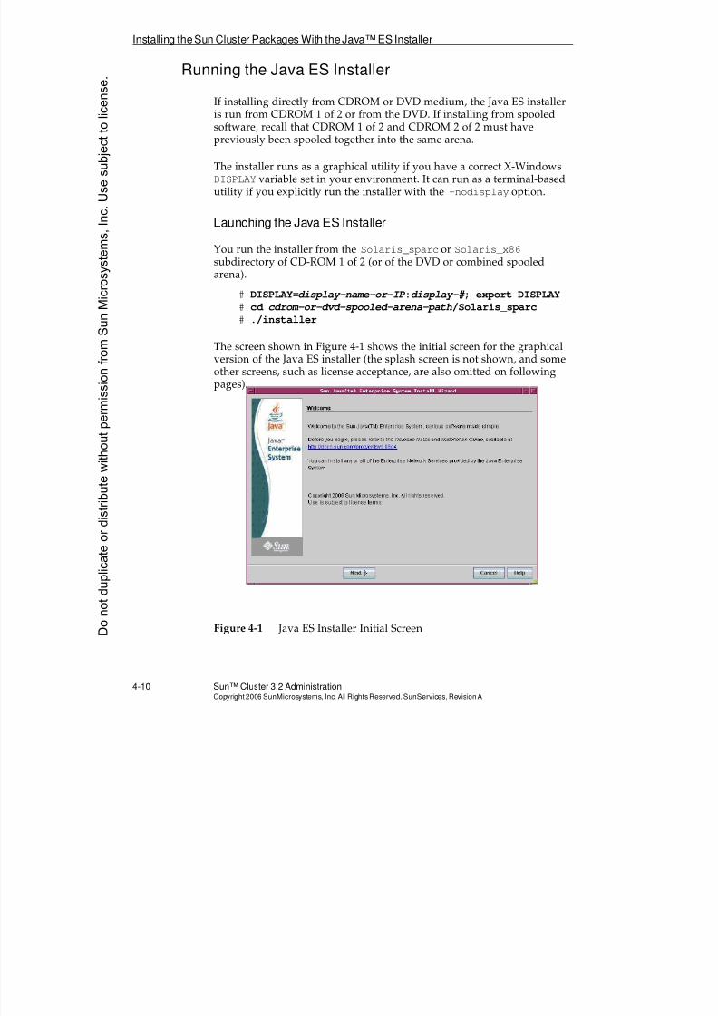
8/4/2019 Sun Cluster 3.2 Administration VC-ES-345
http://slidepdf.com/reader/full/sun-cluster-32-administration-vc-es-345 158/585
Installing the Sun Cluster Packages With theJava™ ES Installer
4-10 Sun™ Cluster 3.2 AdministrationCopyright2006 SunMicrosystems, Inc. AllRights Reserved.SunServices,RevisionA
Running the Java ES Installer
If installing directly from CDROM or DVD medium, the Java ES installeris run from CDROM 1 of 2 or from the DVD. If installing from spooledsoftware, recall that CDROM 1 of 2 and CDROM 2 of 2 must have
previously been spooled together into the same arena.
The installer runs as a graphical utility if you have a correct X-WindowsDISPLAY variable set in your environment. It can run as a terminal-basedutility if you explicitly run the installer with the -nodisplay option.
Launching the Java ES Installer
You run the installer from the Solaris_sparc or Solaris_x86subdirectory of CD-ROM 1 of 2 (or of the DVD or combined spooled
arena).
# DISPLAY=display-name-or-IP :display-# ; export DISPLAY
# cd cdrom-or-dvd-spooled-arena-path/Solaris_sparc
# ./installer
The screen shown in Figure 4-1 shows the initial screen for the graphicalversion of the Java ES installer (the splash screen is not shown, and someother screens, such as license acceptance, are also omitted on followingpages).
Figure 4-1 Java ES Installer Initial ScreenDonotduplicate
ordistributewithoutpermissionfrom SunMicrosystems,Inc.Usesubject
tolicense.
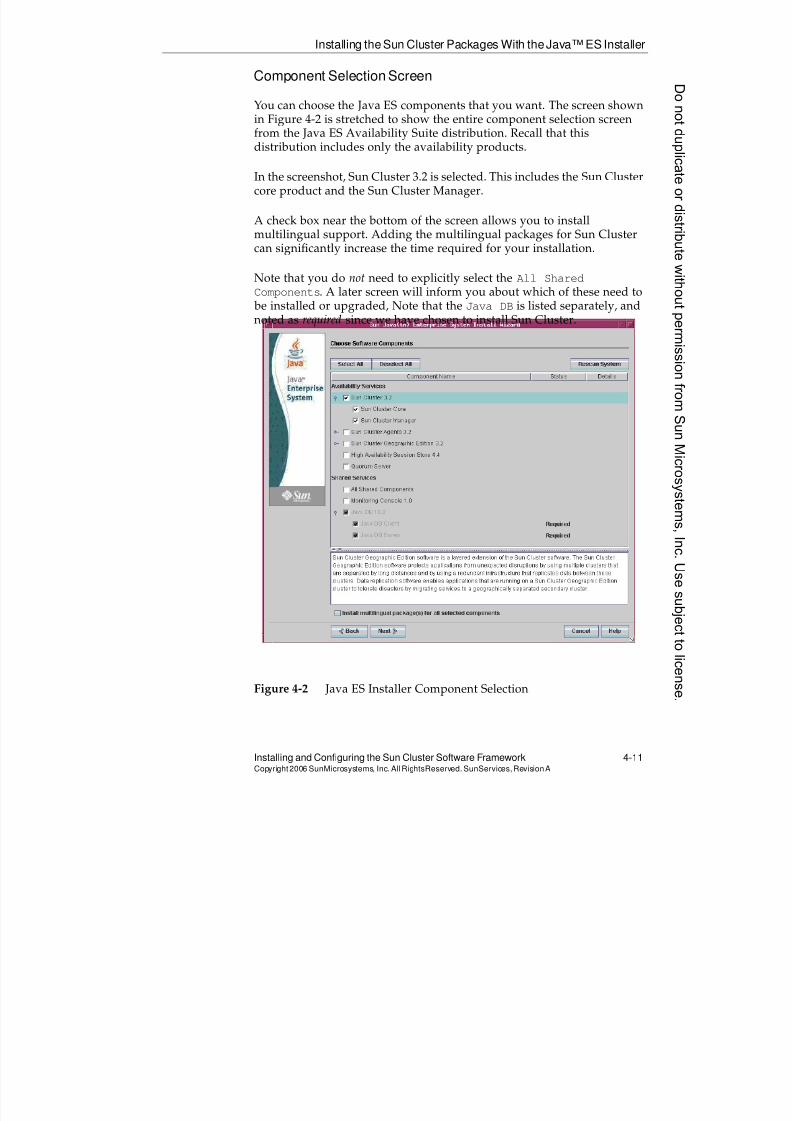
8/4/2019 Sun Cluster 3.2 Administration VC-ES-345
http://slidepdf.com/reader/full/sun-cluster-32-administration-vc-es-345 159/585
Installing the Sun Cluster Packages With theJava™ ES Installer
Installing and Configuring the Sun Cluster Software Framework 4-11Copyright2006 SunMicrosystems, Inc. AllRightsReserved. SunServices,RevisionA
Component Selection Screen
You can choose the Java ES components that you want. The screen shownin Figure 4-2 is stretched to show the entire component selection screenfrom the Java ES Availability Suite distribution. Recall that this
distribution includes only the availability products.
In the screenshot, Sun Cluster 3.2 is selected. This includes the Sun Clustercore product and the Sun Cluster Manager.
A check box near the bottom of the screen allows you to installmultilingual support. Adding the multilingual packages for Sun Clustercan significantly increase the time required for your installation.
Note that you do not need to explicitly select the All Shared
Components. A later screen will inform you about which of these need to
be installed or upgraded, Note that the Java DB is listed separately, andnoted as required since we have chosen to install Sun Cluster.
Figure 4-2 Java ES Installer Component Selection
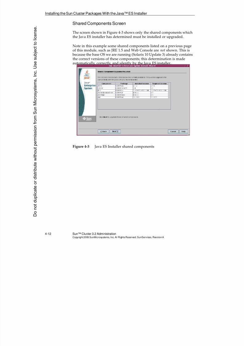
8/4/2019 Sun Cluster 3.2 Administration VC-ES-345
http://slidepdf.com/reader/full/sun-cluster-32-administration-vc-es-345 160/585
Installing the Sun Cluster Packages With theJava™ ES Installer
4-12 Sun™ Cluster 3.2 AdministrationCopyright2006 SunMicrosystems, Inc. AllRights Reserved.SunServices,RevisionA
Shared Components Screen
The screen shown in Figure 4-3 shows only the shared components whichthe Java ES installer has determined must be installed or upgraded.
Note in this example some shared components listed on a previous pageof this module, such as JRE 1.5 and Web Console are not shown. This is because the base OS we are running (Solaris 10 Update 3) already containsthe correct versions of these components; this determination is madeautomatically, correctly, and silently by the Java ES installer.
Figure 4-3 Java ES Installer shared components
Donotduplicate
ordistributewithoutpermissionfrom SunMicrosystems,Inc.Usesubject
tolicense.
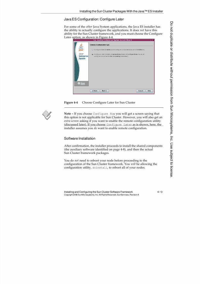
8/4/2019 Sun Cluster 3.2 Administration VC-ES-345
http://slidepdf.com/reader/full/sun-cluster-32-administration-vc-es-345 161/585
8/4/2019 Sun Cluster 3.2 Administration VC-ES-345
http://slidepdf.com/reader/full/sun-cluster-32-administration-vc-es-345 162/585
Installing the Sun Cluster Packages With theJava™ ES Installer
4-14 Sun™ Cluster 3.2 AdministrationCopyright2006 SunMicrosystems, Inc. AllRights Reserved.SunServices,RevisionA
Configuring the User rootEnvironment
The root login environment should include the following search path andman page information:
PATH=$PATH:/usr/cluster/bin
MANPATH=$MANPATH:/usr/cluster/man:/usr/share/man
Donotduplicate
ordistributewithoutpermissionfrom SunMicrosystems,Inc.Usesubject
tolicense.
8/4/2019 Sun Cluster 3.2 Administration VC-ES-345
http://slidepdf.com/reader/full/sun-cluster-32-administration-vc-es-345 163/585
Sun Cluster Framework Configuration
Installing and Configuring the Sun Cluster Software Framework 4-15Copyright2006 SunMicrosystems, Inc. AllRightsReserved. SunServices,RevisionA
Sun Cluster Framework Configuration
The Sun Cluster configuration is performed using one of the followingtwo methods:
q Using the scinstall utility interactively – This is the most commonmethod of configuring Sun Cluster, and the only one that isdescribed in detail in this module.
q Using JumpStart software off a jumpstart server – The scinstall
can be run on the jumpstart server to provision the jumpstart serverso that the client (node) performs cluster configuration as part of jumpstart finish scripts.
If you used this method, you would manually provision the jumpstart server one of two ways:
q
Provide clients a flash image from a cluster node on which the Java ES installer had been used to install the cluster softwarepackages. The jumpstart finish scripts then run the scinstallconfiguration functionality.
q Provide the clients a completely fresh OS (or a flash image froma Solaris without cluster packages.). The jumpstart finish scripsthen run the Java ES installer to provide the cluster packages,and then run the scinstall configuration functionality.
Understanding the installmodeFlag
As you configure Sun Cluster software on cluster nodes and reboot thenodes into the cluster, a special flag called the installmode flag is set inthe cluster CCR. When this flag is set, the following happens:
q The first node installed (node ID 1) has a quorum vote of one.
q All other nodes have a quorum vote of zero.
This allows you to complete the rebooting of the second node into thecluster while maintaining the quorum mathematics rules. If the second
node had a vote (making a total of two in the cluster), the first nodewould kernel panic when the second node was rebooted after the clustersoftware was installed because the first node would lose operationalquorum.
8/4/2019 Sun Cluster 3.2 Administration VC-ES-345
http://slidepdf.com/reader/full/sun-cluster-32-administration-vc-es-345 164/585
Sun Cluster Framework Configuration
4-16 Sun™ Cluster 3.2 AdministrationCopyright2006 SunMicrosystems, Inc. AllRights Reserved.SunServices,RevisionA
One important side effect of the installmode flag is that you must becareful not to reboot the first node (node ID 1) until you can choosequorum devices and eliminate (reset) the installmode flag. If youaccidentally reboot the first node, all the other nodes will kernel panic because they have zero votes out of a possible total of one.
If the installation is a single-node cluster, the installmode flag is not set.Post-installation steps to choose a quorum device and reset theinstallmode flag are unnecessary.
Automatic Quorum Configuration (Two-Node ClusterOnly)
On a two-node cluster only, you have the option of having the scinstall
utility insert a script that automatically chooses your quorum device asthe second node boots into the cluster. The defaults will always be toaccept the option.
The quorum device chosen will be the first dual-ported disk or LUN (theone with the lowest DID number).
If you choose to allow automatic quorum configuration, the installmodeflag is automatically reset for you after the quorum is automaticallyconfigured.
You can disable two-node cluster automatic quorum configuration for oneof the following reasons:
q You want to choose the quorum yourself.
q You have a dual-ported disk or LUN that is not capable of being aquorum device.
q You want to use a NAS device as a quorum device.
q You want to use the quorum server as a quorum device.
Donotduplicate
ordistributewithoutpermissionfrom SunMicrosystems,Inc.Usesubject
tolicense.
8/4/2019 Sun Cluster 3.2 Administration VC-ES-345
http://slidepdf.com/reader/full/sun-cluster-32-administration-vc-es-345 165/585
Sun Cluster Framework Configuration
Installing and Configuring the Sun Cluster Software Framework 4-17Copyright2006 SunMicrosystems, Inc. AllRightsReserved. SunServices,RevisionA
Automatic Reset of installmodeWithout QuorumDevices (Clusters With More Than Two Nodes Only)
In clusters with more than two nodes, the scinstall inserts a script to
automatically reset theinstallmode
flag. It will not automaticallyconfigure a quorum device. You still have to do that manually after theinstallation. By resetting installmode, each node is assigned its propersingle quorum vote.
Configuration Information Required to Run scinstall
The following information is required by scinstall and should beprepared in advance.
Name of the Cluster and Names of All the Nodes
The cluster name is just a name agreed upon by the nodes, it is not a namethat resolves to an IP address.
The nodes in the cluster must be able to resolve each other’s host name. Iffor some reason this is true but the names are not in each node’s/etc/hostsfile (the names can be resolved through only NIS or DNS, for
example), the /etc/hosts file is automatically modified to include thesenames.
8/4/2019 Sun Cluster 3.2 Administration VC-ES-345
http://slidepdf.com/reader/full/sun-cluster-32-administration-vc-es-345 166/585
Sun Cluster Framework Configuration
4-18 Sun™ Cluster 3.2 AdministrationCopyright2006 SunMicrosystems, Inc. AllRights Reserved.SunServices,RevisionA
Cluster Transport IP Network Number and Netmask
As described in module 3, the default cluster transport IP address range begins with 172.16.0.0 and the netmask is 255.255.248.0. You should keepthe default if it causes no conflict with anything else visible on any other
other networks. It is perfectly fine for multiple clusters to use the sameaddresses on their cluster transports, as these addresses are not visibleanywhere outside the cluster.
Note – The netmask refers to the range of IP addresses that are reservedfor all possible cluster transport addresses. This will not match the actualnetmask that you will see configured on the transport adapters if youcheck using ifconfig -a.
If you need to specify a different IP address range for the transport, youcan do so.
Rather than being asked initially for a specific netmask, you will be askedfor the anticipated maximum number of nodes and physical privatenetworks. A suggested netmask is then calculated for you.
Cluster Transport Adapters and Switches
You must be prepared to identify transport adapters on at least the firstnode on which you run scinstall. On other nodes you will normally let
scinstall use its auto-discovery feature to automatically determine thetransport adapters.
You can define a two-node cluster topology as using switches or justusing point-to-point cables. This does not even need to match the actualtopology; the software really has no way of telling. It is just the definitionsin the Cluster Configuration Repository (CCR), and whichever way youdefine it will be the way it is presented when you view the clusterconfiguration using command-line commands or the graphical web-basedadministration tool.
Names that you provide for switches are arbitrary, and are just used tomatch up transport connections between the various nodes.
Port names for specific switch connections are arbitrary except for SCIswitches. For SCI, the port name must match the switch port number towhich an actual cable is connected.
Donotduplicate
ordistributewithoutpermissionfrom SunMicrosystems,Inc.Usesubject
tolicense.
8/4/2019 Sun Cluster 3.2 Administration VC-ES-345
http://slidepdf.com/reader/full/sun-cluster-32-administration-vc-es-345 167/585
Sun Cluster Framework Configuration
Installing and Configuring the Sun Cluster Software Framework 4-19Copyright2006 SunMicrosystems, Inc. AllRightsReserved. SunServices,RevisionA
Partition or Placeholder File System for the/global/.devices/node@#File
You must have a partition on the root disk (recommended size 512Mbytes) for this file system. While the default is that this is covered with
an empty placeholder file system mounted on /globaldevices, you will be asked if you have a different placeholder file system or just an unusedpartition.
8/4/2019 Sun Cluster 3.2 Administration VC-ES-345
http://slidepdf.com/reader/full/sun-cluster-32-administration-vc-es-345 168/585
8/4/2019 Sun Cluster 3.2 Administration VC-ES-345
http://slidepdf.com/reader/full/sun-cluster-32-administration-vc-es-345 169/585
8/4/2019 Sun Cluster 3.2 Administration VC-ES-345
http://slidepdf.com/reader/full/sun-cluster-32-administration-vc-es-345 170/585
Sun Cluster Framework Configuration
4-22 Sun™ Cluster 3.2 AdministrationCopyright2006 SunMicrosystems, Inc. AllRights Reserved.SunServices,RevisionA
Configuring Cluster Nodes One at a Time
If you choose this method, you run scinstall separately on each node.
You must complete scinstall and reboot into the cluster on the firstnode. This becomes the sponsor node to the remaining nodes.
If you have more than two nodes you can run scinstall simultaneouslyon all but the first node, but it might be hard to predict which node getsassigned which node ID. If you care, you should just run scinstall onthe remaining nodes one at a time, and wait for each node to boot into thecluster before starting the next one.
Typical Installation Compared to Custom Installation
Both the all-at-once and one-at-a-time methods have Typical and Custom
configuration options (to make a total of four variations).
The Typical configuration mode assumes the following responses:
q It uses network address 172.16.0.0 with netmask 255.255.248.0
for the cluster interconnect.
q It assumes that you want to perform autodiscovery of clustertransport adapters on the other nodes with the all-at-once method.(On the one-node-at-a-time method, it asks you if you want to useautodiscovery in both Typical and Custom modes.)
q It uses the names switch1 and switch2 for the two transportswitches and assumes the use of switches even for a two-nodecluster.
q It assumes that you have the standard empty /globaldevices
mounted as an empty file system with the recommended size(512 Mbytes) to be remounted as the /global/.devices/node@#filesystem.
q It assumes that you want to use standard system authentication
(not DES authentication) for new nodes configuring themselves intothe cluster.
Donotduplicate
ordistributewithoutpermissionfrom SunMicrosystems,Inc.Usesubject
tolicense.
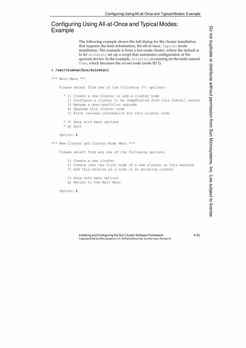
8/4/2019 Sun Cluster 3.2 Administration VC-ES-345
http://slidepdf.com/reader/full/sun-cluster-32-administration-vc-es-345 171/585
Configuring UsingAll-at-Once and Typical Modes: Example
Installing and Configuring the Sun Cluster Software Framework 4-23Copyright2006 SunMicrosystems, Inc. AllRightsReserved. SunServices,RevisionA
Configuring Using All-at-Once and Typical Modes:Example
The following example shows the full dialog for the cluster installation
that requires the least information, the all-at-once, Typical modeinstallation. The example is from a two-node cluster, where the default isto let scinstall set up a script that automates configuration of thequorum device. In the example, scinstall is running on the node namedtheo, which becomes the second node (node ID 2).
# /usr/cluster/bin/scinstall
*** Main Menu ***
Please select from one of the following (*) options:
* 1) Create a new cluster or add a cluster node
2) Configure a cluster to be JumpStarted from this install server
3) Manage a dual-partition upgrade
4) Upgrade this cluster node
5) Print release information for this cluster node
* ?) Help with menu options
* q) Quit
Option: 1
*** New Cluster and Cluster Node Menu ***
Please select from any one of the following options:
1) Create a new cluster
2) Create just the first node of a new cluster on this machine
3) Add this machine as a node in an existing cluster
?) Help with menu options
q) Return to the Main Menu
Option: 1
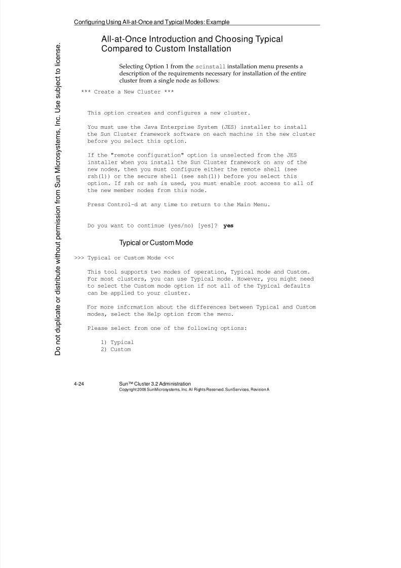
8/4/2019 Sun Cluster 3.2 Administration VC-ES-345
http://slidepdf.com/reader/full/sun-cluster-32-administration-vc-es-345 172/585
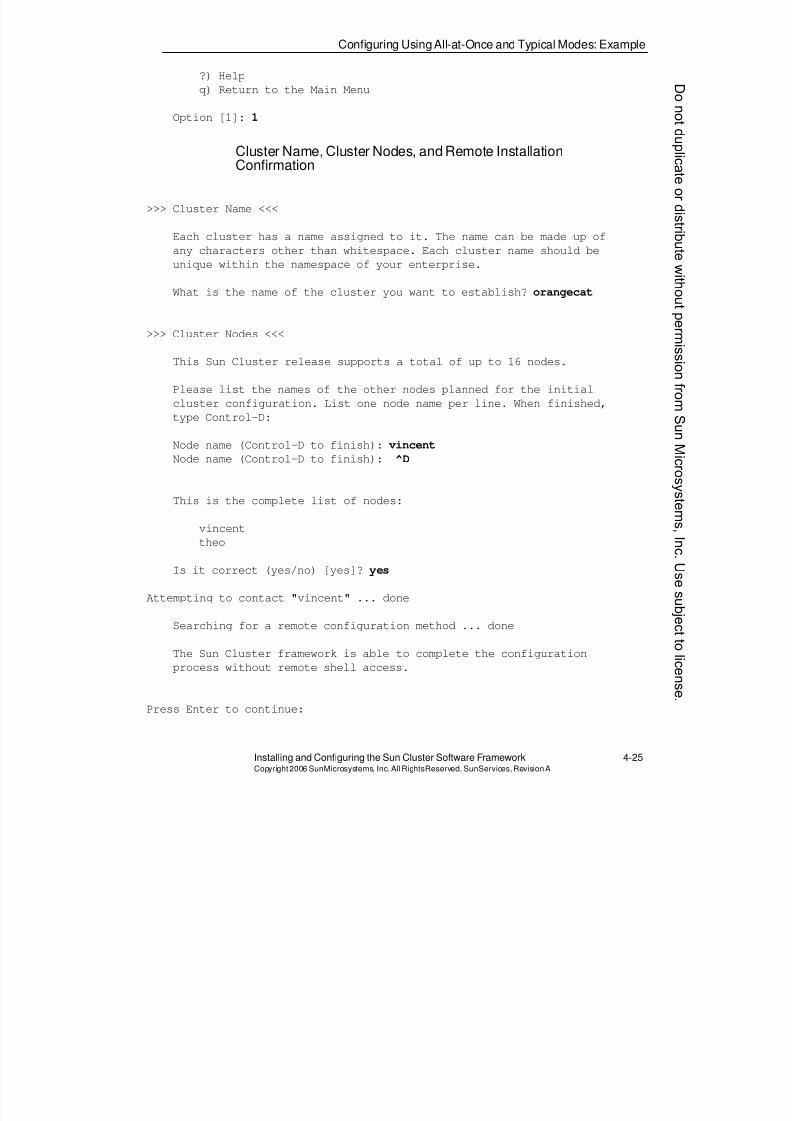
8/4/2019 Sun Cluster 3.2 Administration VC-ES-345
http://slidepdf.com/reader/full/sun-cluster-32-administration-vc-es-345 173/585
Configuring UsingAll-at-Once and Typical Modes: Example
Installing and Configuring the Sun Cluster Software Framework 4-25Copyright2006 SunMicrosystems, Inc. AllRightsReserved. SunServices,RevisionA
?) Help
q) Return to the Main Menu
Option [1]: 1
Cluster Name, Cluster Nodes, and Remote InstallationConfirmation
>>> Cluster Name <<<
Each cluster has a name assigned to it. The name can be made up of
any characters other than whitespace. Each cluster name should be
unique within the namespace of your enterprise.
What is the name of the cluster you want to establish? orangecat
>>> Cluster Nodes <<<
This Sun Cluster release supports a total of up to 16 nodes.
Please list the names of the other nodes planned for the initial
cluster configuration. List one node name per line. When finished,
type Control-D:
Node name (Control-D to finish): vincent
Node name (Control-D to finish): ^D
This is the complete list of nodes:
vincent
theo
Is it correct (yes/no) [yes]? yes
Attempting to contact "vincent" ... done
Searching for a remote configuration method ... done
The Sun Cluster framework is able to complete the configuration
process without remote shell access.
Press Enter to continue:
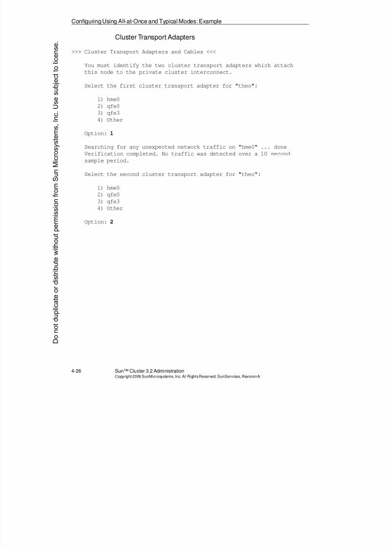
8/4/2019 Sun Cluster 3.2 Administration VC-ES-345
http://slidepdf.com/reader/full/sun-cluster-32-administration-vc-es-345 174/585
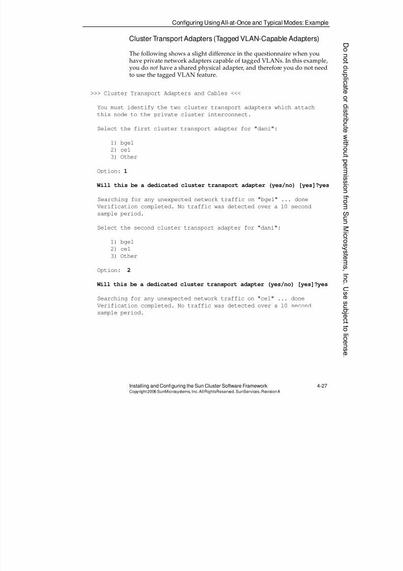
8/4/2019 Sun Cluster 3.2 Administration VC-ES-345
http://slidepdf.com/reader/full/sun-cluster-32-administration-vc-es-345 175/585
Configuring UsingAll-at-Once and Typical Modes: Example
Installing and Configuring the Sun Cluster Software Framework 4-27Copyright2006 SunMicrosystems, Inc. AllRightsReserved. SunServices,RevisionA
Cluster Transport Adapters (Tagged VLAN-Capable Adapters)
The following shows a slight difference in the questionnaire when youhave private network adapters capable of tagged VLANs. In this example,you do not have a shared physical adapter, and therefore you do not need
to use the tagged VLAN feature.
>>> Cluster Transport Adapters and Cables <<<
You must identify the two cluster transport adapters which attach
this node to the private cluster interconnect.
Select the first cluster transport adapter for "dani":
1) bge1
2) ce1
3) Other
Option: 1
Will this be a dedicated cluster transport adapter (yes/no) [yes]?yes
Searching for any unexpected network traffic on "bge1" ... done
Verification completed. No traffic was detected over a 10 second
sample period.
Select the second cluster transport adapter for "dani":
1) bge1
2) ce1
3) Other
Option: 2
Will this be a dedicated cluster transport adapter (yes/no) [yes]?yes
Searching for any unexpected network traffic on "ce1" ... done
Verification completed. No traffic was detected over a 10 second
sample period.
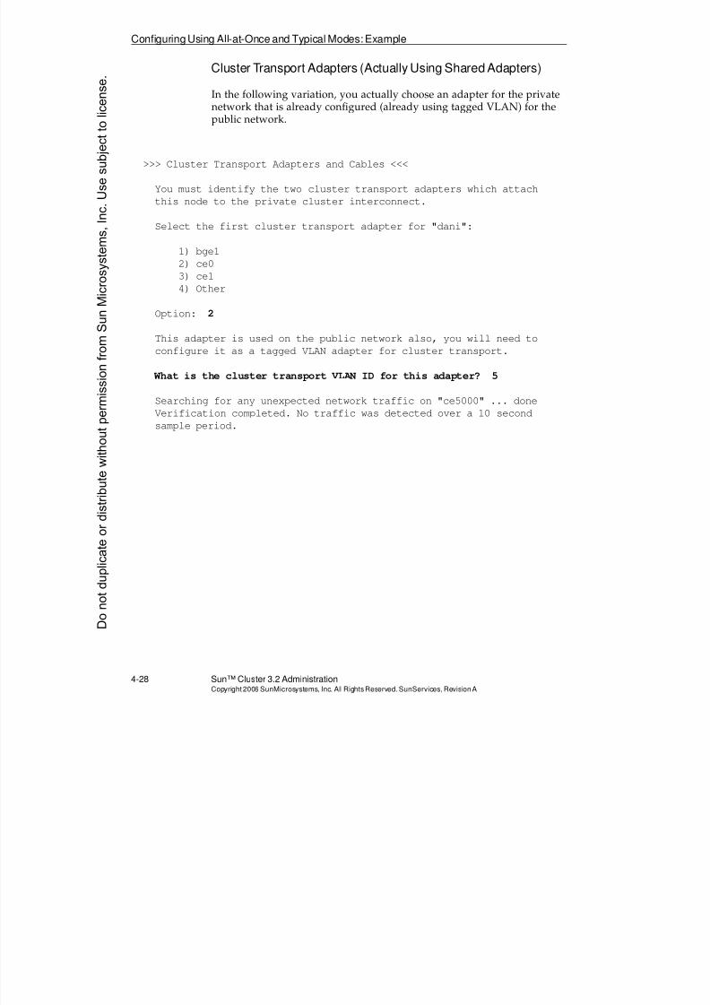
8/4/2019 Sun Cluster 3.2 Administration VC-ES-345
http://slidepdf.com/reader/full/sun-cluster-32-administration-vc-es-345 176/585
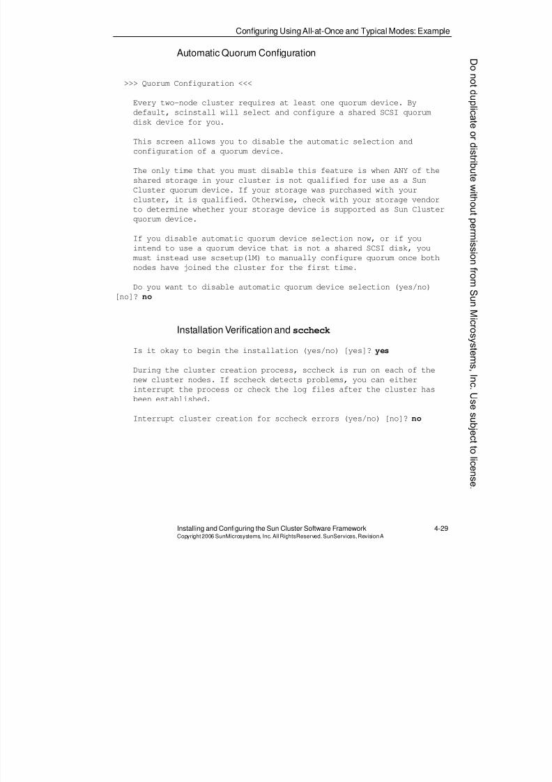
8/4/2019 Sun Cluster 3.2 Administration VC-ES-345
http://slidepdf.com/reader/full/sun-cluster-32-administration-vc-es-345 177/585
Configuring UsingAll-at-Once and Typical Modes: Example
Installing and Configuring the Sun Cluster Software Framework 4-29Copyright2006 SunMicrosystems, Inc. AllRightsReserved. SunServices,RevisionA
Automatic Quorum Configuration
>>> Quorum Configuration <<<
Every two-node cluster requires at least one quorum device. Bydefault, scinstall will select and configure a shared SCSI quorum
disk device for you.
This screen allows you to disable the automatic selection and
configuration of a quorum device.
The only time that you must disable this feature is when ANY of the
shared storage in your cluster is not qualified for use as a Sun
Cluster quorum device. If your storage was purchased with your
cluster, it is qualified. Otherwise, check with your storage vendor
to determine whether your storage device is supported as Sun Clusterquorum device.
If you disable automatic quorum device selection now, or if you
intend to use a quorum device that is not a shared SCSI disk, you
must instead use scsetup(1M) to manually configure quorum once both
nodes have joined the cluster for the first time.
Do you want to disable automatic quorum device selection (yes/no)
[no]? no
Installation Verification andsccheck
Is it okay to begin the installation (yes/no) [yes]? yes
During the cluster creation process, sccheck is run on each of the
new cluster nodes. If sccheck detects problems, you can either
interrupt the process or check the log files after the cluster has
been established.
Interrupt cluster creation for sccheck errors (yes/no) [no]? no
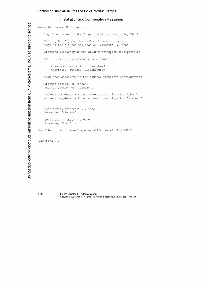
8/4/2019 Sun Cluster 3.2 Administration VC-ES-345
http://slidepdf.com/reader/full/sun-cluster-32-administration-vc-es-345 178/585
Configuring Using All-at-Once and Typical Modes: Example
4-30 Sun™ Cluster 3.2 AdministrationCopyright2006 SunMicrosystems, Inc. AllRights Reserved.SunServices,RevisionA
Installation and Configuration Messages
Installation and Configuration
Log file - /var/cluster/logs/install/scinstall.log.20852
Testing for "/globaldevices" on "theo" ... done
Testing for "/globaldevices" on "vincent" ... done
Starting discovery of the cluster transport configuration.
The following connections were discovered:
theo:hme0 switch1 vincent:hme0
theo:qfe0 switch2 vincent:qfe0
Completed discovery of the cluster transport configuration.
Started sccheck on "theo".
Started sccheck on "vincent".
sccheck completed with no errors or warnings for "theo".
sccheck completed with no errors or warnings for "vincent".
Configuring "vincent" ... done
Rebooting "vincent" ...
Configuring "theo" ... done
Rebooting "theo" ...
Log file - /var/cluster/logs/install/scinstall.log.20852
Rebooting ...
Donotduplicate
ordistributewithoutpermissionfrom SunMicrosystems,Inc.Usesubject
tolicense.
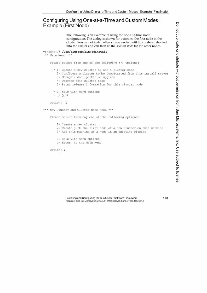
8/4/2019 Sun Cluster 3.2 Administration VC-ES-345
http://slidepdf.com/reader/full/sun-cluster-32-administration-vc-es-345 179/585
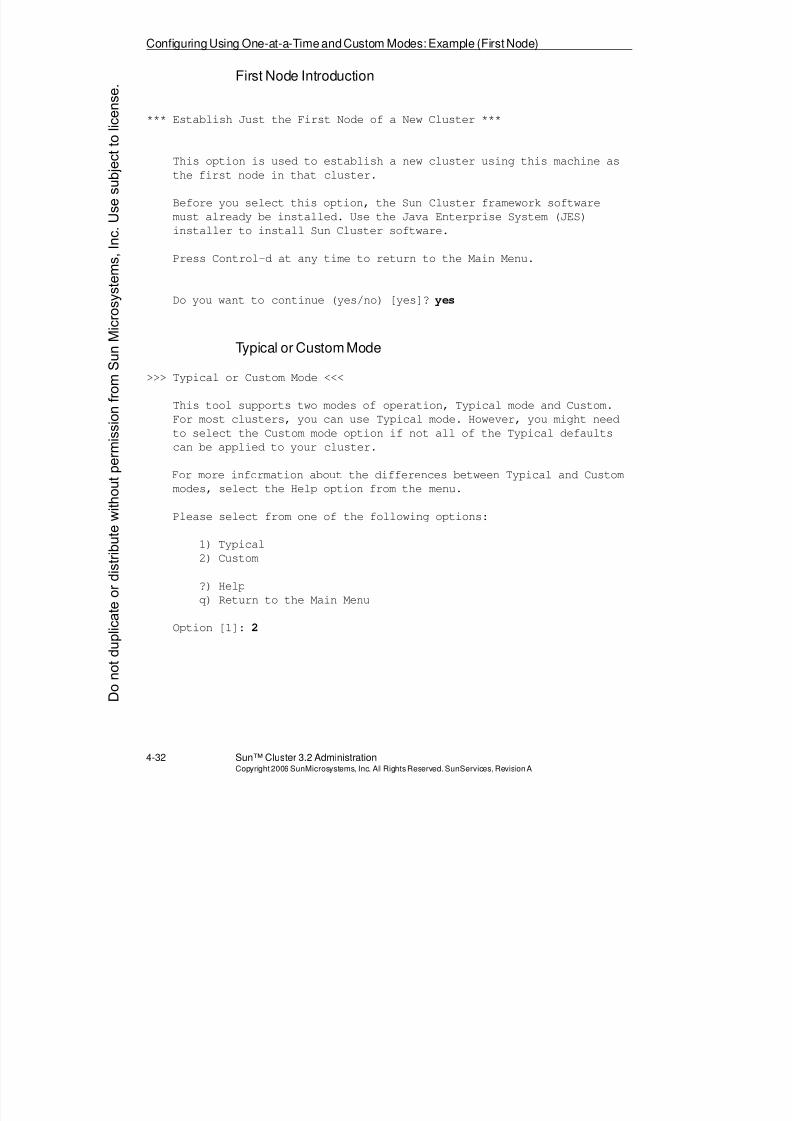
8/4/2019 Sun Cluster 3.2 Administration VC-ES-345
http://slidepdf.com/reader/full/sun-cluster-32-administration-vc-es-345 180/585
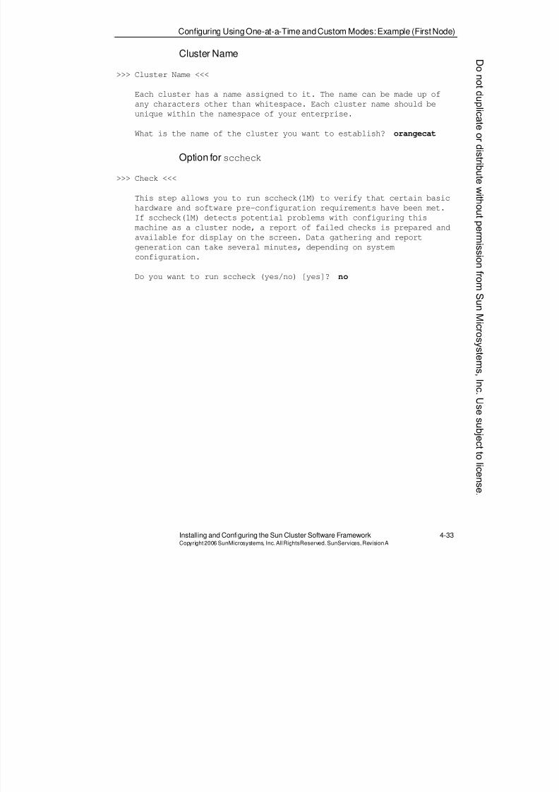
8/4/2019 Sun Cluster 3.2 Administration VC-ES-345
http://slidepdf.com/reader/full/sun-cluster-32-administration-vc-es-345 181/585
Configuring UsingOne-at-a-Time andCustom Modes: Example (First Node)
Installing and Configuring the Sun Cluster Software Framework 4-33Copyright2006 SunMicrosystems, Inc. AllRightsReserved. SunServices,RevisionA
Cluster Name
>>> Cluster Name <<<
Each cluster has a name assigned to it. The name can be made up of
any characters other than whitespace. Each cluster name should beunique within the namespace of your enterprise.
What is the name of the cluster you want to establish? orangecat
Option forsccheck
>>> Check <<<
This step allows you to run sccheck(1M) to verify that certain basic
hardware and software pre-configuration requirements have been met.
If sccheck(1M) detects potential problems with configuring this
machine as a cluster node, a report of failed checks is prepared and
available for display on the screen. Data gathering and report
generation can take several minutes, depending on system
configuration.
Do you want to run sccheck (yes/no) [yes]? no
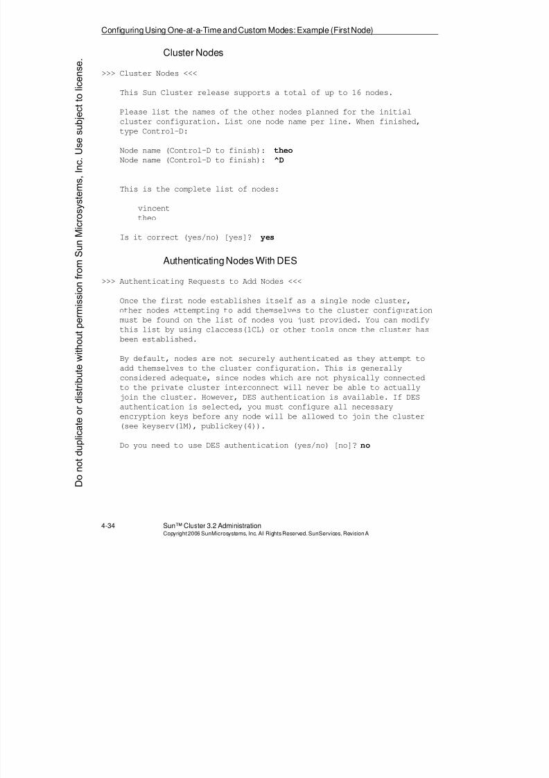
8/4/2019 Sun Cluster 3.2 Administration VC-ES-345
http://slidepdf.com/reader/full/sun-cluster-32-administration-vc-es-345 182/585
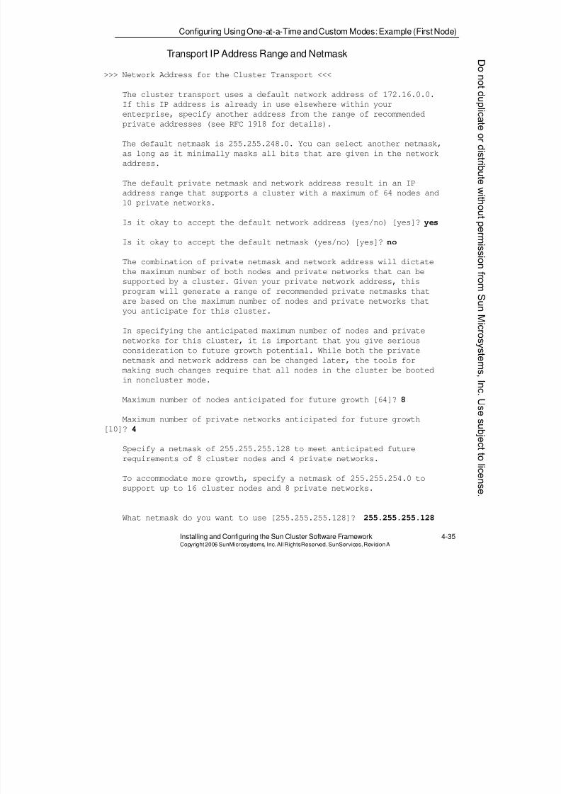
8/4/2019 Sun Cluster 3.2 Administration VC-ES-345
http://slidepdf.com/reader/full/sun-cluster-32-administration-vc-es-345 183/585
Configuring UsingOne-at-a-Time andCustom Modes: Example (First Node)
Installing and Configuring the Sun Cluster Software Framework 4-35Copyright2006 SunMicrosystems, Inc. AllRightsReserved. SunServices,RevisionA
Transport IP Address Range and Netmask
>>> Network Address for the Cluster Transport <<<
The cluster transport uses a default network address of 172.16.0.0.
If this IP address is already in use elsewhere within yourenterprise, specify another address from the range of recommended
private addresses (see RFC 1918 for details).
The default netmask is 255.255.248.0. You can select another netmask,
as long as it minimally masks all bits that are given in the network
address.
The default private netmask and network address result in an IP
address range that supports a cluster with a maximum of 64 nodes and
10 private networks.
Is it okay to accept the default network address (yes/no) [yes]? yes
Is it okay to accept the default netmask (yes/no) [yes]? no
The combination of private netmask and network address will dictate
the maximum number of both nodes and private networks that can be
supported by a cluster. Given your private network address, this
program will generate a range of recommended private netmasks that
are based on the maximum number of nodes and private networks that
you anticipate for this cluster.
In specifying the anticipated maximum number of nodes and private
networks for this cluster, it is important that you give serious
consideration to future growth potential. While both the private
netmask and network address can be changed later, the tools for
making such changes require that all nodes in the cluster be booted
in noncluster mode.
Maximum number of nodes anticipated for future growth [64]? 8
Maximum number of private networks anticipated for future growth
[10]? 4
Specify a netmask of 255.255.255.128 to meet anticipated future
requirements of 8 cluster nodes and 4 private networks.
To accommodate more growth, specify a netmask of 255.255.254.0 to
support up to 16 cluster nodes and 8 private networks.
What netmask do you want to use [255.255.255.128]? 255.255.255.128
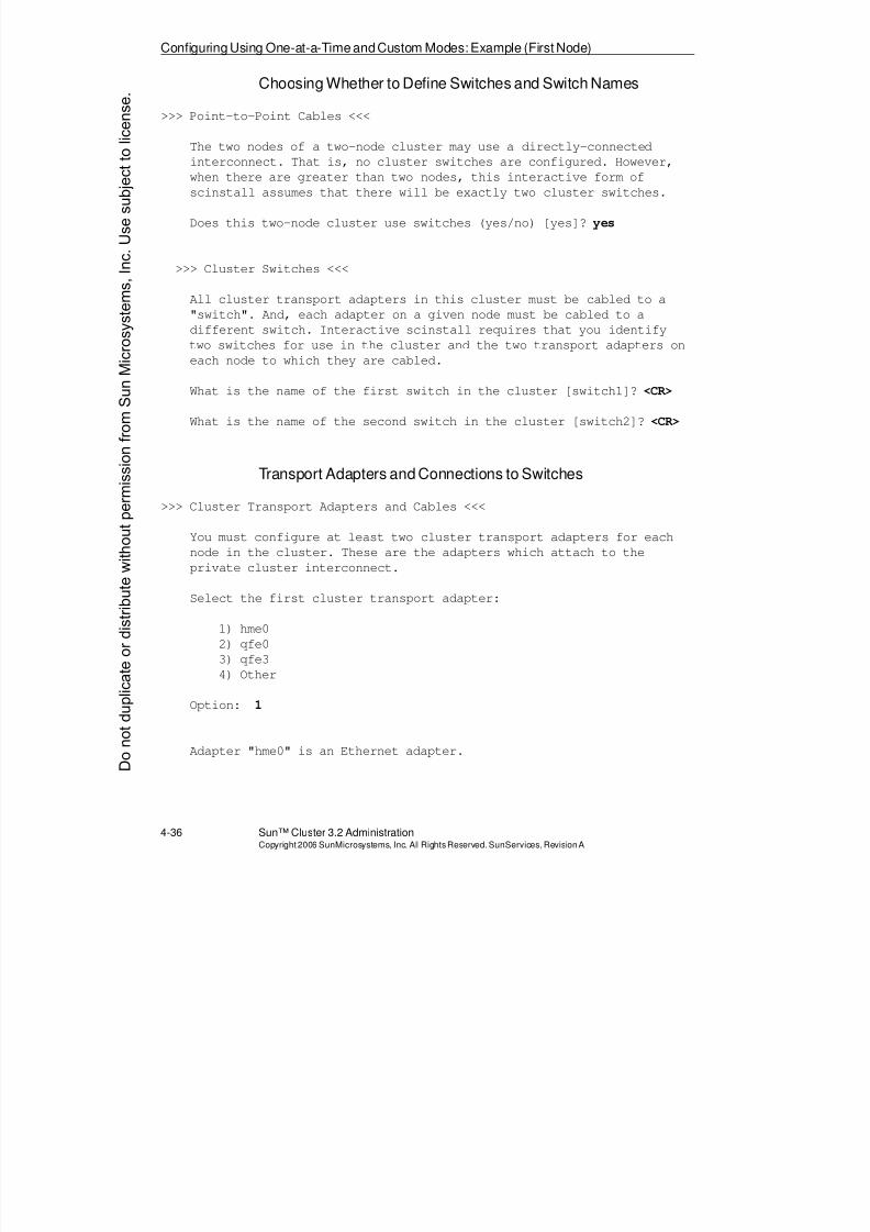
8/4/2019 Sun Cluster 3.2 Administration VC-ES-345
http://slidepdf.com/reader/full/sun-cluster-32-administration-vc-es-345 184/585
Configuring Using One-at-a-Time andCustom Modes: Example (First Node)
4-36 Sun™ Cluster 3.2 AdministrationCopyright2006 SunMicrosystems, Inc. AllRights Reserved.SunServices,RevisionA
Choosing Whether to Define Switches and Switch Names
>>> Point-to-Point Cables <<<
The two nodes of a two-node cluster may use a directly-connected
interconnect. That is, no cluster switches are configured. However,when there are greater than two nodes, this interactive form of
scinstall assumes that there will be exactly two cluster switches.
Does this two-node cluster use switches (yes/no) [yes]? yes
>>> Cluster Switches <<<
All cluster transport adapters in this cluster must be cabled to a
"switch". And, each adapter on a given node must be cabled to a
different switch. Interactive scinstall requires that you identifytwo switches for use in the cluster and the two transport adapters on
each node to which they are cabled.
What is the name of the first switch in the cluster [switch1]? <CR>
What is the name of the second switch in the cluster [switch2]? <CR>
Transport Adapters and Connections to Switches
>>> Cluster Transport Adapters and Cables <<<
You must configure at least two cluster transport adapters for each
node in the cluster. These are the adapters which attach to the
private cluster interconnect.
Select the first cluster transport adapter:
1) hme0
2) qfe0
3) qfe3
4) Other
Option: 1
Adapter "hme0" is an Ethernet adapter.
Donotduplicate
ordistributewithoutpermissionfrom SunMicrosystems,Inc.Usesubject
tolicense.
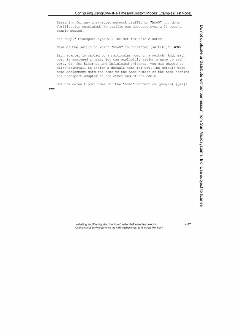
8/4/2019 Sun Cluster 3.2 Administration VC-ES-345
http://slidepdf.com/reader/full/sun-cluster-32-administration-vc-es-345 185/585
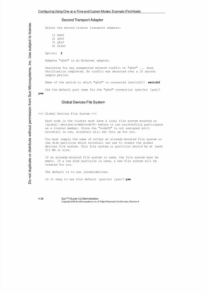
8/4/2019 Sun Cluster 3.2 Administration VC-ES-345
http://slidepdf.com/reader/full/sun-cluster-32-administration-vc-es-345 186/585

8/4/2019 Sun Cluster 3.2 Administration VC-ES-345
http://slidepdf.com/reader/full/sun-cluster-32-administration-vc-es-345 187/585
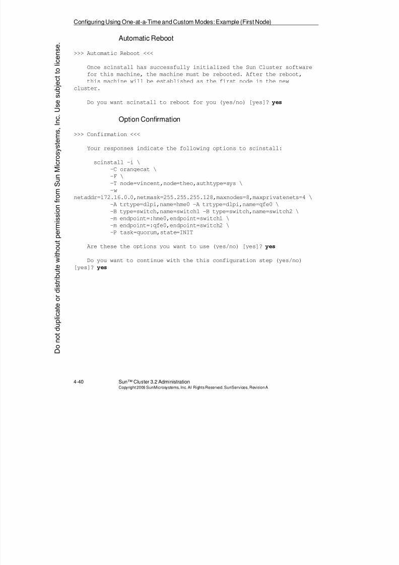
8/4/2019 Sun Cluster 3.2 Administration VC-ES-345
http://slidepdf.com/reader/full/sun-cluster-32-administration-vc-es-345 188/585
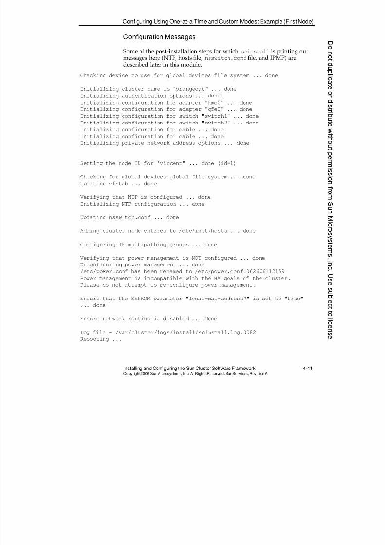
8/4/2019 Sun Cluster 3.2 Administration VC-ES-345
http://slidepdf.com/reader/full/sun-cluster-32-administration-vc-es-345 189/585
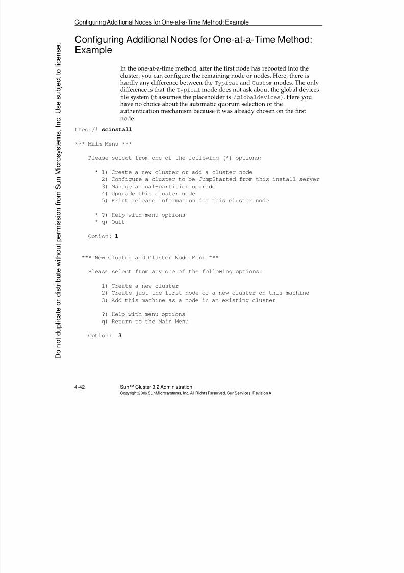
8/4/2019 Sun Cluster 3.2 Administration VC-ES-345
http://slidepdf.com/reader/full/sun-cluster-32-administration-vc-es-345 190/585
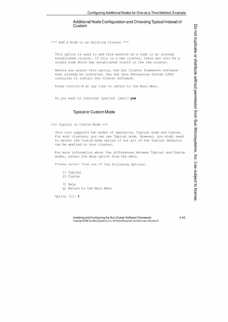
8/4/2019 Sun Cluster 3.2 Administration VC-ES-345
http://slidepdf.com/reader/full/sun-cluster-32-administration-vc-es-345 191/585
ConfiguringAdditional Nodes for One-at-a-Time Method: Example
Installing and Configuring the Sun Cluster Software Framework 4-43Copyright2006 SunMicrosystems, Inc. AllRightsReserved. SunServices,RevisionA
Additional Node Configuration and Choosing Typical Instead ofCustom
*** Add a Node to an Existing Cluster ***
This option is used to add this machine as a node in an already
established cluster. If this is a new cluster, there may only be a
single node which has established itself in the new cluster.
Before you select this option, the Sun Cluster framework software
must already be installed. Use the Java Enterprise System (JES)
installer to install Sun Cluster software.
Press Control-d at any time to return to the Main Menu.
Do you want to continue (yes/no) [yes]? yes
Typical or Custom Mode
>>> Typical or Custom Mode <<<
This tool supports two modes of operation, Typical mode and Custom.
For most clusters, you can use Typical mode. However, you might need
to select the Custom mode option if not all of the Typical defaults
can be applied to your cluster.
For more information about the differences between Typical and Custom
modes, select the Help option from the menu.
Please select from one of the following options:
1) Typical
2) Custom
?) Help
q) Return to the Main Menu
Option [1]: 1
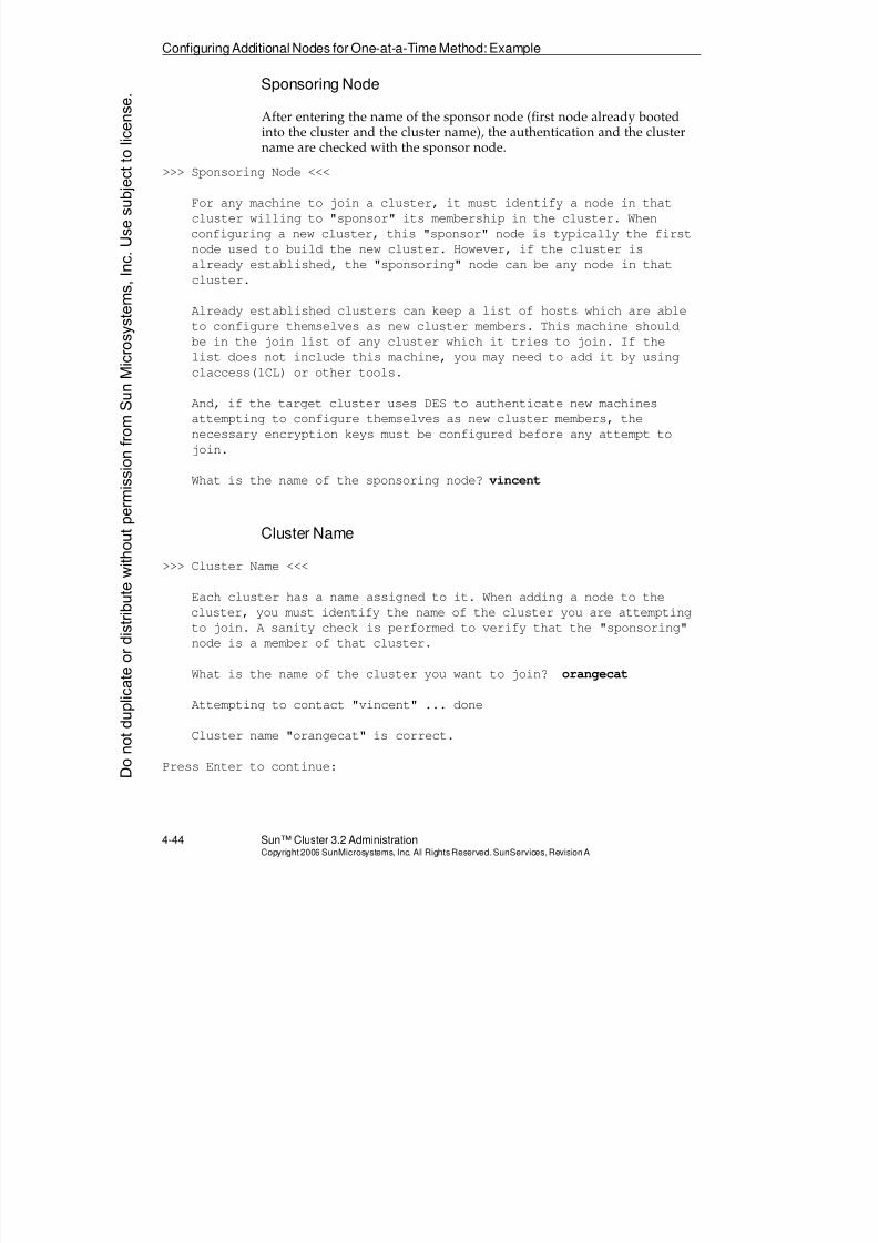
8/4/2019 Sun Cluster 3.2 Administration VC-ES-345
http://slidepdf.com/reader/full/sun-cluster-32-administration-vc-es-345 192/585
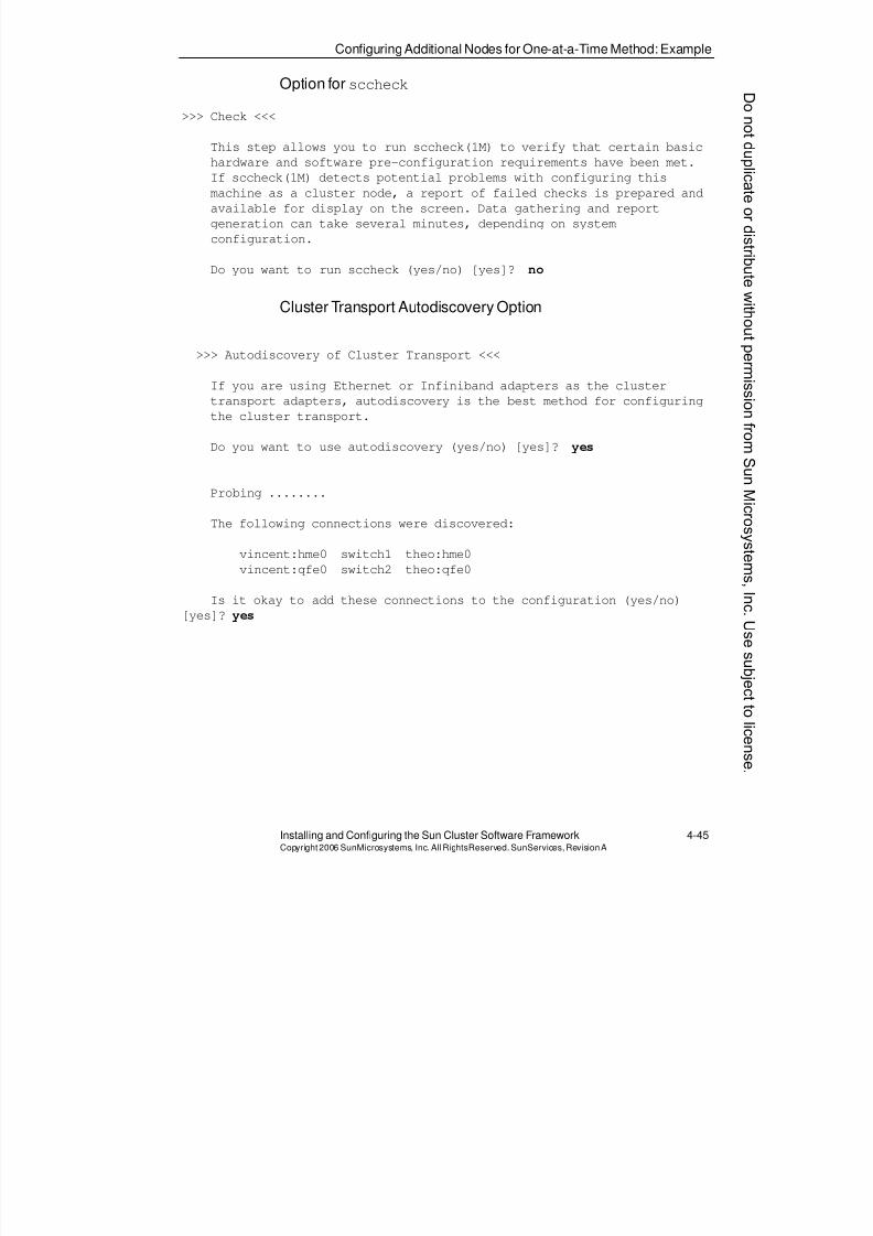
8/4/2019 Sun Cluster 3.2 Administration VC-ES-345
http://slidepdf.com/reader/full/sun-cluster-32-administration-vc-es-345 193/585
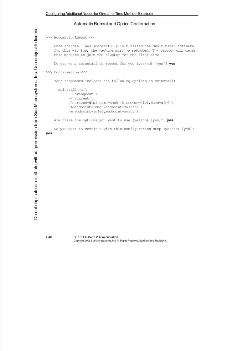
8/4/2019 Sun Cluster 3.2 Administration VC-ES-345
http://slidepdf.com/reader/full/sun-cluster-32-administration-vc-es-345 194/585
Configuring Additional Nodes for One-at-a-Time Method: Example
4-46 Sun™ Cluster 3.2 AdministrationCopyright2006 SunMicrosystems, Inc. AllRights Reserved.SunServices,RevisionA
Automatic Reboot and Option Confirmation
>>> Automatic Reboot <<<
Once scinstall has successfully initialized the Sun Cluster softwarefor this machine, the machine must be rebooted. The reboot will cause
this machine to join the cluster for the first time.
Do you want scinstall to reboot for you (yes/no) [yes]? yes
>>> Confirmation <<<
Your responses indicate the following options to scinstall:
scinstall -i \
-C orangecat \-N vincent \
-A trtype=dlpi,name=hme0 -A trtype=dlpi,name=qfe0 \
-m endpoint=:hme0,endpoint=switch1 \
-m endpoint=:qfe0,endpoint=switch2
Are these the options you want to use (yes/no) [yes]? yes
Do you want to continue with this configuration step (yes/no) [yes]?
yes
Donotduplicate
ordistributewithoutpermissionfrom SunMicrosystems,Inc.Usesubject
tolicense.
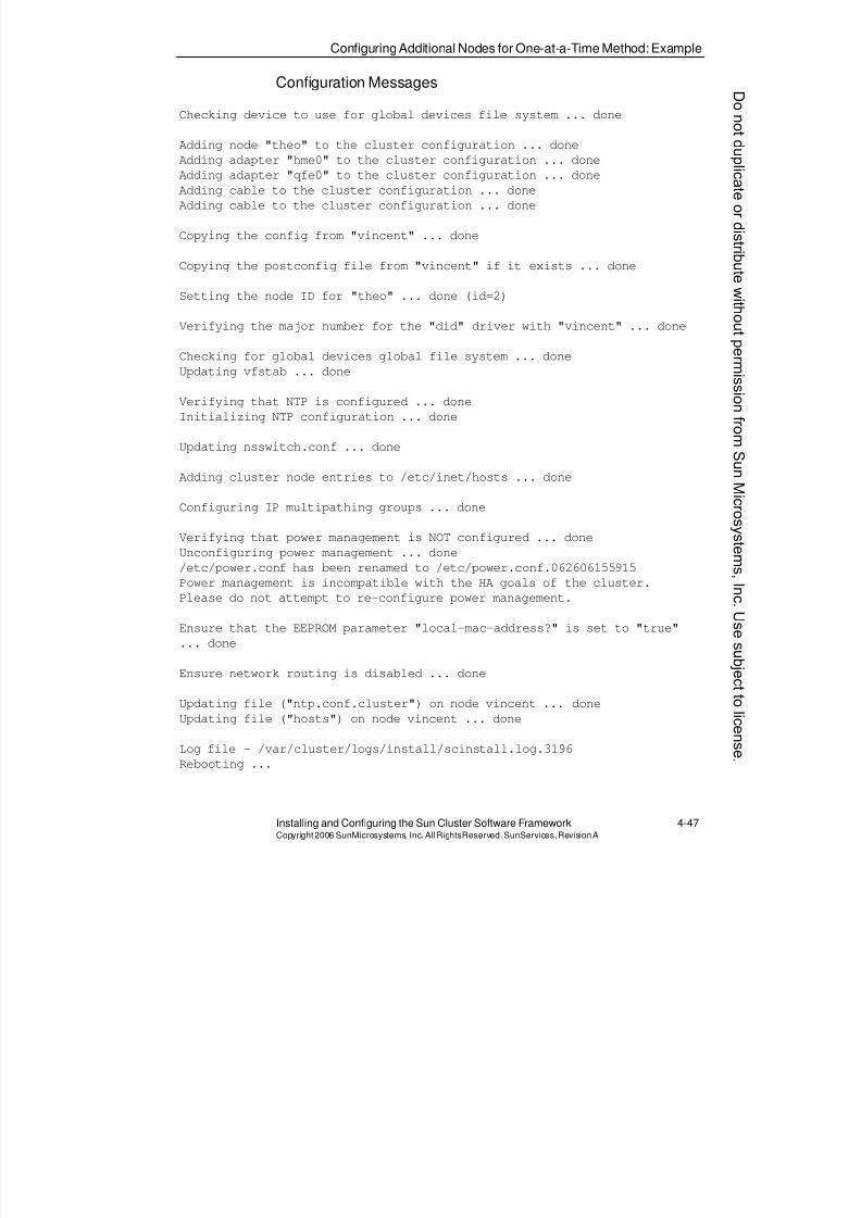
8/4/2019 Sun Cluster 3.2 Administration VC-ES-345
http://slidepdf.com/reader/full/sun-cluster-32-administration-vc-es-345 195/585
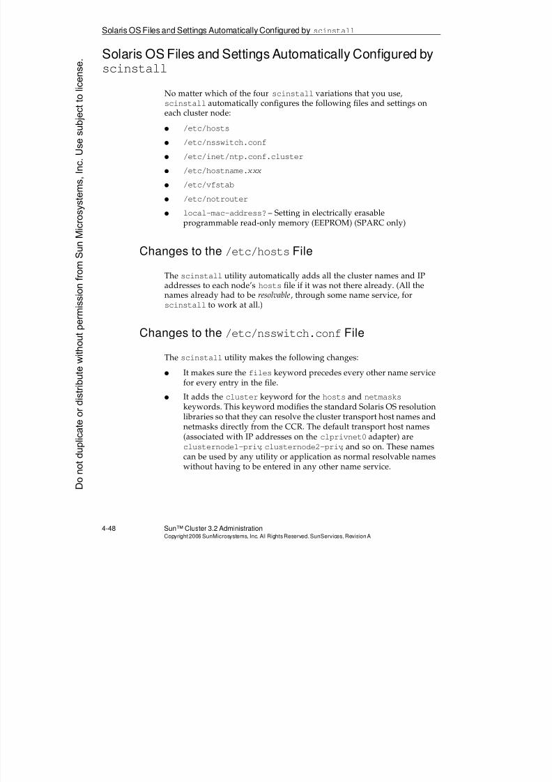
8/4/2019 Sun Cluster 3.2 Administration VC-ES-345
http://slidepdf.com/reader/full/sun-cluster-32-administration-vc-es-345 196/585
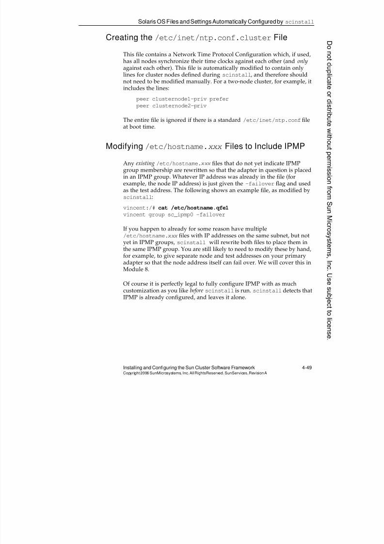
8/4/2019 Sun Cluster 3.2 Administration VC-ES-345
http://slidepdf.com/reader/full/sun-cluster-32-administration-vc-es-345 197/585
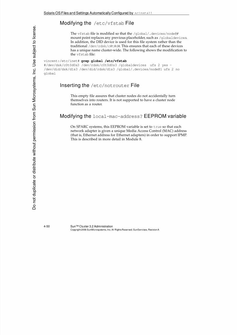
8/4/2019 Sun Cluster 3.2 Administration VC-ES-345
http://slidepdf.com/reader/full/sun-cluster-32-administration-vc-es-345 198/585
Solaris OS Files and Settings Automatically Configured byscinstall
4-50 Sun™ Cluster 3.2 AdministrationCopyright2006 SunMicrosystems, Inc. AllRights Reserved.SunServices,RevisionA
Modifying the /etc/vfstabFile
The vfstab file is modified so that the /global/.devices/node@#mount point replaces any previous placeholder, such as /globaldevices.In addition, the DID device is used for this file system rather than the
traditional /dev/rdsk/c#t#d#. This ensures that each of these deviceshas a unique name cluster-wide. The following shows the modification tothe vfstab file:
vincent:/etc/inet# grep global /etc/vfstab
#/dev/dsk/c0t0d0s3 /dev/rdsk/c0t0d0s3 /globaldevices ufs 2 yes -
/dev/did/dsk/d1s3 /dev/did/rdsk/d1s3 /global/.devices/node@1 ufs 2 no
global
Inserting the /etc/notrouterFile
This empty file assures that cluster nodes do not accidentally turnthemselves into routers. It is not supported to have a cluster nodefunction as a router.
Modifying the local-mac-address?EEPROM variable
On SPARC systems, this EEPROM variable is set to true so that eachnetwork adapter is given a unique Media Access Control (MAC) address
(that is, Ethernet address for Ethernet adapters) in order to support IPMP.This is described in more detail in Module 8.
Donotduplicate
ordistributewithoutpermissionfrom SunMicrosystems,Inc.Usesubject
tolicense.
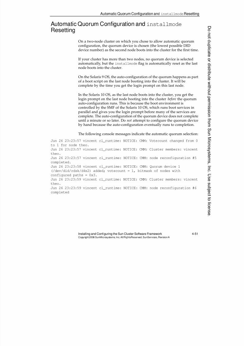
8/4/2019 Sun Cluster 3.2 Administration VC-ES-345
http://slidepdf.com/reader/full/sun-cluster-32-administration-vc-es-345 199/585
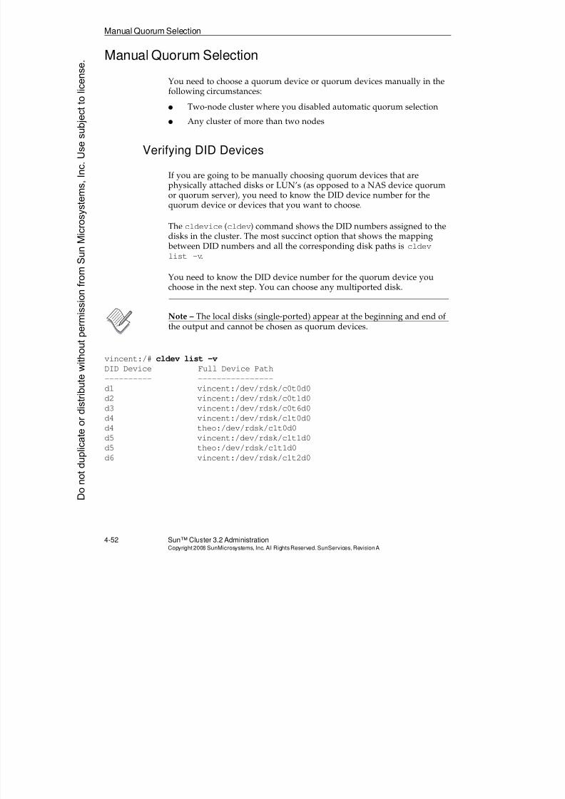
8/4/2019 Sun Cluster 3.2 Administration VC-ES-345
http://slidepdf.com/reader/full/sun-cluster-32-administration-vc-es-345 200/585
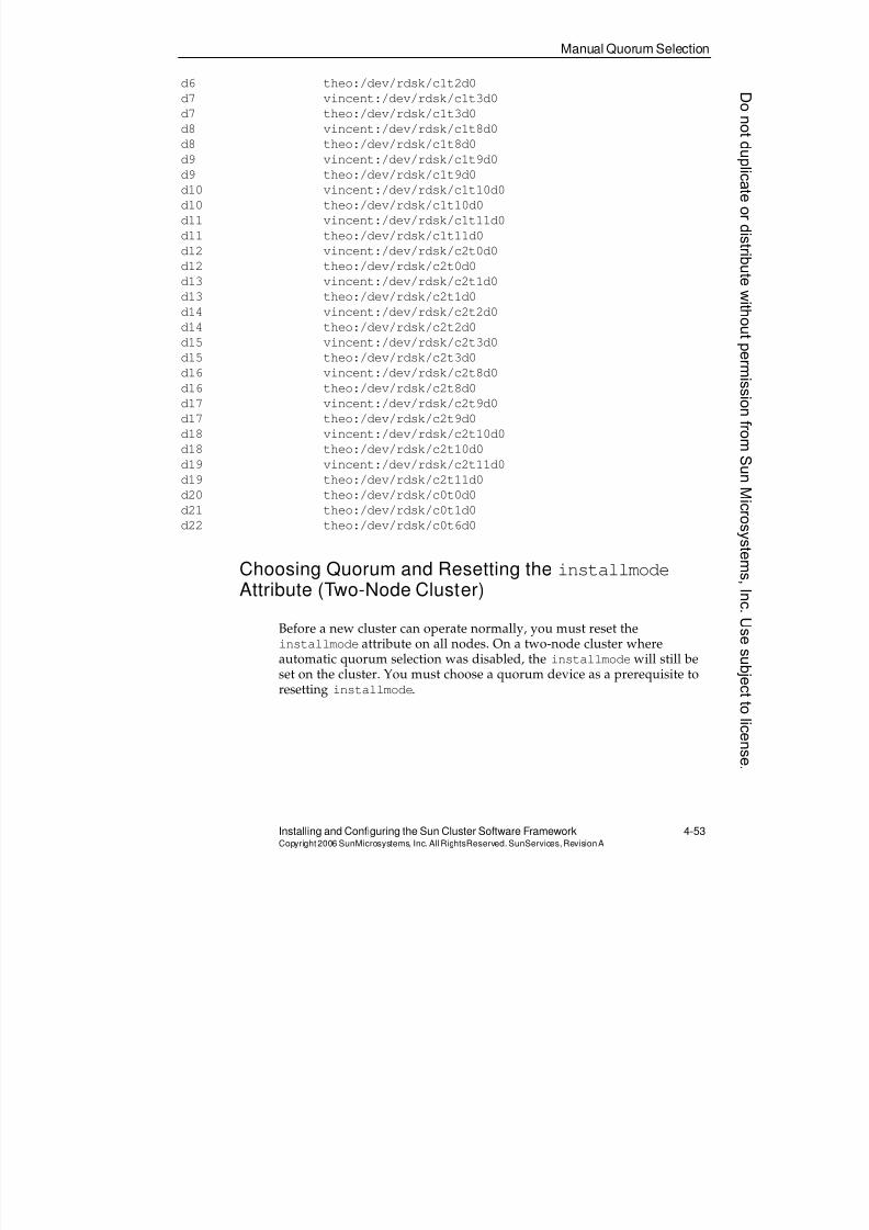
8/4/2019 Sun Cluster 3.2 Administration VC-ES-345
http://slidepdf.com/reader/full/sun-cluster-32-administration-vc-es-345 201/585
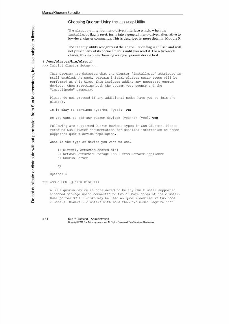
8/4/2019 Sun Cluster 3.2 Administration VC-ES-345
http://slidepdf.com/reader/full/sun-cluster-32-administration-vc-es-345 202/585
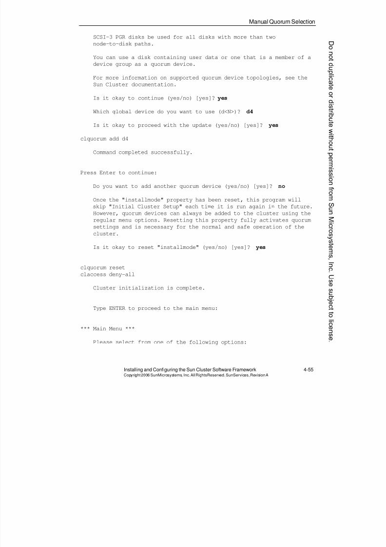
8/4/2019 Sun Cluster 3.2 Administration VC-ES-345
http://slidepdf.com/reader/full/sun-cluster-32-administration-vc-es-345 203/585
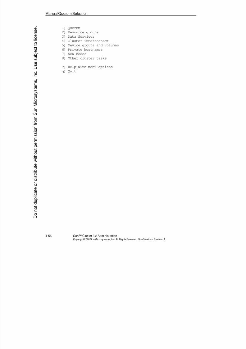
8/4/2019 Sun Cluster 3.2 Administration VC-ES-345
http://slidepdf.com/reader/full/sun-cluster-32-administration-vc-es-345 204/585
Manual Quorum Selection
4-56 Sun™ Cluster 3.2 AdministrationCopyright2006 SunMicrosystems, Inc. AllRights Reserved.SunServices,RevisionA
1) Quorum
2) Resource groups
3) Data Services
4) Cluster interconnect
5) Device groups and volumes
6) Private hostnames
7) New nodes
8) Other cluster tasks
?) Help with menu options
q) Quit
Donotduplicate
ordistributewithoutpermissionfrom SunMicrosystems,Inc.Usesubject
tolicense.
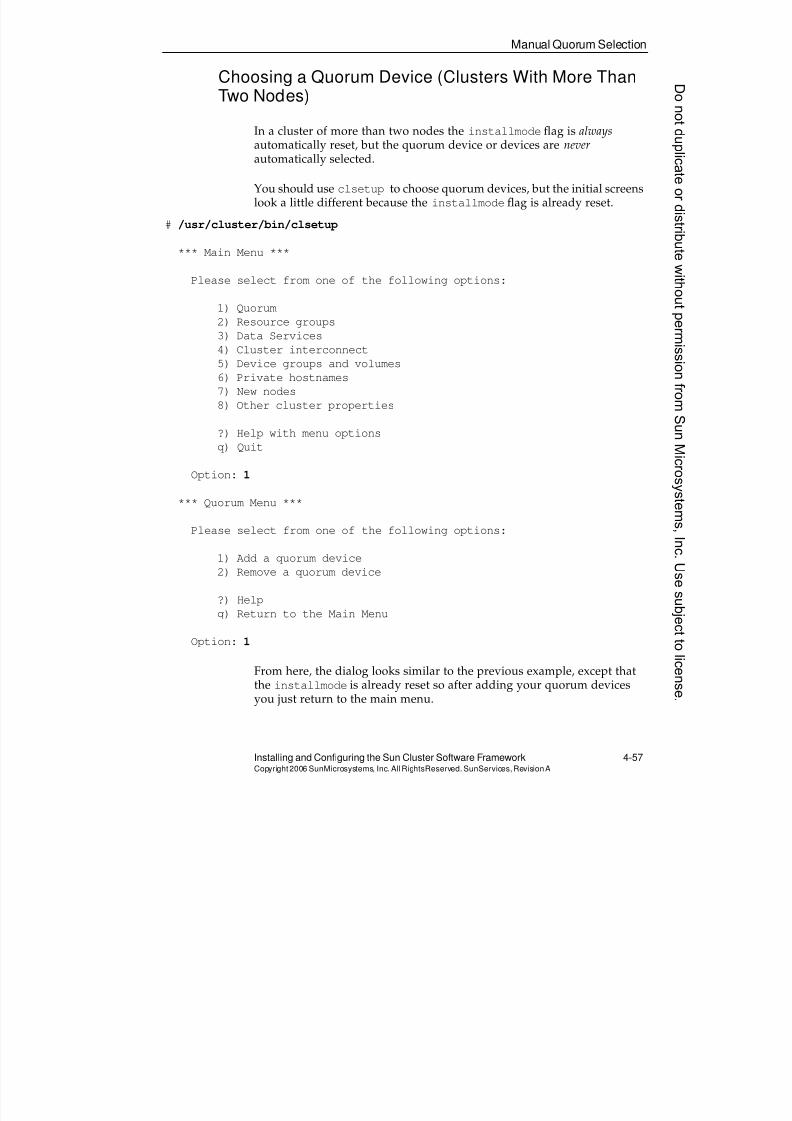
8/4/2019 Sun Cluster 3.2 Administration VC-ES-345
http://slidepdf.com/reader/full/sun-cluster-32-administration-vc-es-345 205/585
8/4/2019 Sun Cluster 3.2 Administration VC-ES-345
http://slidepdf.com/reader/full/sun-cluster-32-administration-vc-es-345 206/585
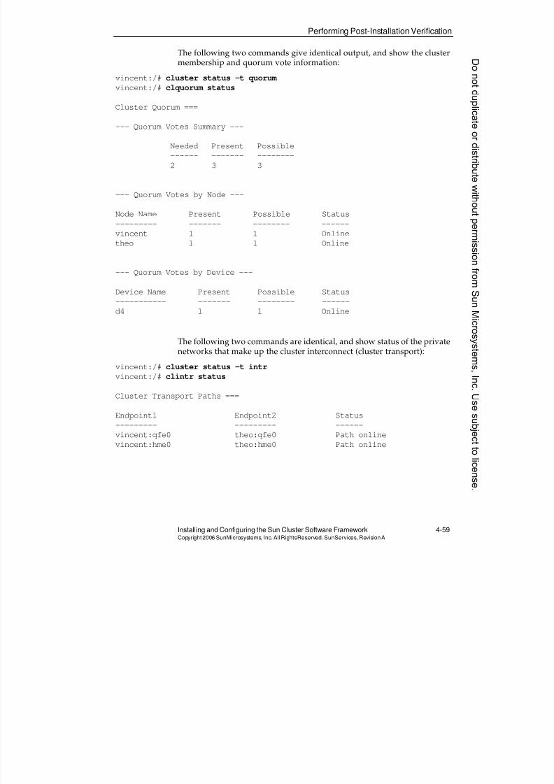
8/4/2019 Sun Cluster 3.2 Administration VC-ES-345
http://slidepdf.com/reader/full/sun-cluster-32-administration-vc-es-345 207/585
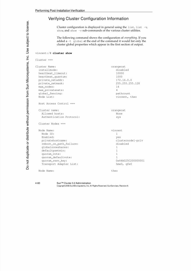
8/4/2019 Sun Cluster 3.2 Administration VC-ES-345
http://slidepdf.com/reader/full/sun-cluster-32-administration-vc-es-345 208/585
Performing Post-Installation Verification
4-60 Sun™ Cluster 3.2 AdministrationCopyright2006 SunMicrosystems, Inc. AllRights Reserved.SunServices,RevisionA
Verifying Cluster Configuration Information
Cluster configuration is displayed in general using the list, list -v,show, and show -v sub-commands of the various cluster utilities.
The following command shows the configuration of everything. If youadded a -t global at the end of the command it would list only thecluster global properties which appear in the first section of output.
vincent:/# cluster show
Cluster ===
Cluster Name: orangecat
installmode: disabled
heartbeat_timeout: 10000heartbeat_quantum: 1000
private_netaddr: 172.16.0.0
private_netmask: 255.255.255.128
max_nodes: 14
max_privatenets: 4
global_fencing: pathcount
Node List: vincent, theo
Host Access Control ===
Cluster name: orangecatAllowed hosts: None
Authentication Protocol: sys
Cluster Nodes ===
Node Name: vincent
Node ID: 1
Enabled: yes
privatehostname: clusternode1-priv
reboot_on_path_failure: disabled
globalzoneshares: 1defaultpsetmin: 1
quorum_vote: 1
quorum_defaultvote: 1
quorum_resv_key: 0x44A025C200000001
Transport Adapter List: hme0, qfe0
Node Name: theoDonotduplicate
ordistributewithoutpermissionfrom SunMicrosystems,Inc.Usesubject
tolicense.
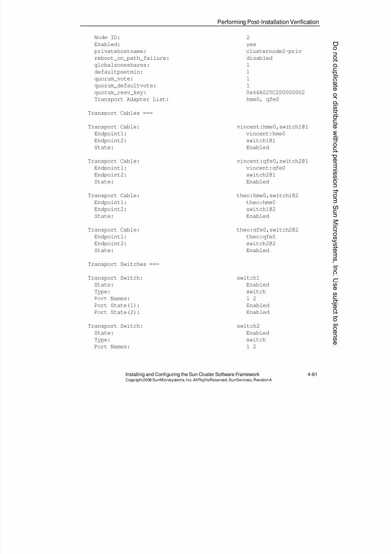
8/4/2019 Sun Cluster 3.2 Administration VC-ES-345
http://slidepdf.com/reader/full/sun-cluster-32-administration-vc-es-345 209/585
Performing Post-Installation Verification
Installing and Configuring the Sun Cluster Software Framework 4-61Copyright2006 SunMicrosystems, Inc. AllRightsReserved. SunServices,RevisionA
Node ID: 2
Enabled: yes
privatehostname: clusternode2-priv
reboot_on_path_failure: disabled
globalzoneshares: 1
defaultpsetmin: 1
quorum_vote: 1
quorum_defaultvote: 1
quorum_resv_key: 0x44A025C200000002
Transport Adapter List: hme0, qfe0
Transport Cables ===
Transport Cable: vincent:hme0,switch1@1
Endpoint1: vincent:hme0
Endpoint2: switch1@1
State: Enabled
Transport Cable: vincent:qfe0,switch2@1
Endpoint1: vincent:qfe0
Endpoint2: switch2@1
State: Enabled
Transport Cable: theo:hme0,switch1@2
Endpoint1: theo:hme0
Endpoint2: switch1@2
State: Enabled
Transport Cable: theo:qfe0,switch2@2
Endpoint1: theo:qfe0
Endpoint2: switch2@2
State: Enabled
Transport Switches ===
Transport Switch: switch1
State: Enabled
Type: switch
Port Names: 1 2Port State(1): Enabled
Port State(2): Enabled
Transport Switch: switch2
State: Enabled
Type: switch
Port Names: 1 2
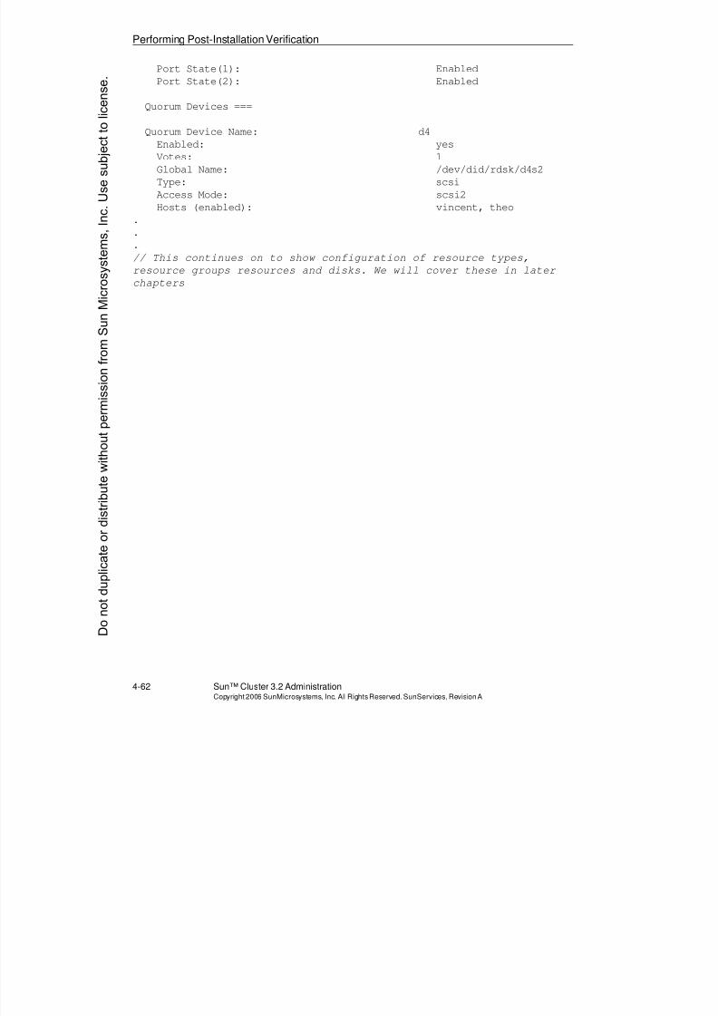
8/4/2019 Sun Cluster 3.2 Administration VC-ES-345
http://slidepdf.com/reader/full/sun-cluster-32-administration-vc-es-345 210/585
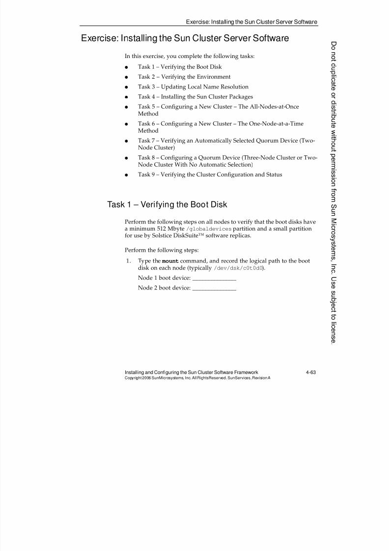
8/4/2019 Sun Cluster 3.2 Administration VC-ES-345
http://slidepdf.com/reader/full/sun-cluster-32-administration-vc-es-345 211/585
Exercise: Installing the Sun Cluster Server Software
Installing and Configuring the Sun Cluster Software Framework 4-63Copyright2006 SunMicrosystems, Inc. AllRightsReserved. SunServices,RevisionA
Exercise: Installing the Sun Cluster Server Software
In this exercise, you complete the following tasks:
q Task 1 – Verifying the Boot Disk
q Task 2 – Verifying the Environment
q Task 3 – Updating Local Name Resolution
q Task 4 – Installing the Sun Cluster Packages
q Task 5 – Configuring a New Cluster – The All-Nodes-at-OnceMethod
q Task 6 – Configuring a New Cluster – The One-Node-at-a-TimeMethod
q Task 7 – Verifying an Automatically Selected Quorum Device (Two-
Node Cluster)q Task 8 – Configuring a Quorum Device (Three-Node Cluster or Two-
Node Cluster With No Automatic Selection)
q Task 9 – Verifying the Cluster Configuration and Status
Task 1 – Verifying the Boot Disk
Perform the following steps on all nodes to verify that the boot disks havea minimum 512 Mbyte /globaldevices partition and a small partitionfor use by Solstice DiskSuite™ software replicas.
Perform the following steps:
1. Type the mount command, and record the logical path to the bootdisk on each node (typically /dev/dsk/c0t0d0).
Node 1 boot device: _______________
Node 2 boot device: _______________
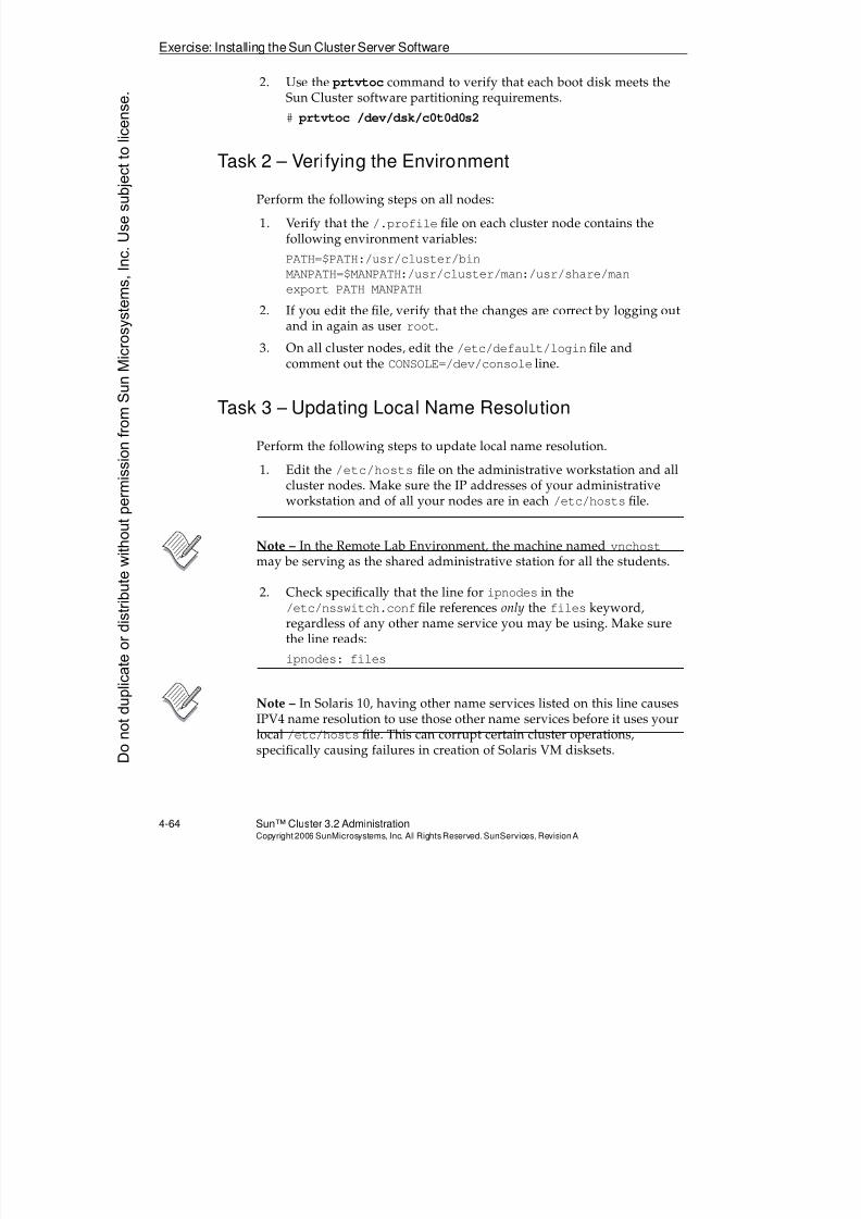
8/4/2019 Sun Cluster 3.2 Administration VC-ES-345
http://slidepdf.com/reader/full/sun-cluster-32-administration-vc-es-345 212/585
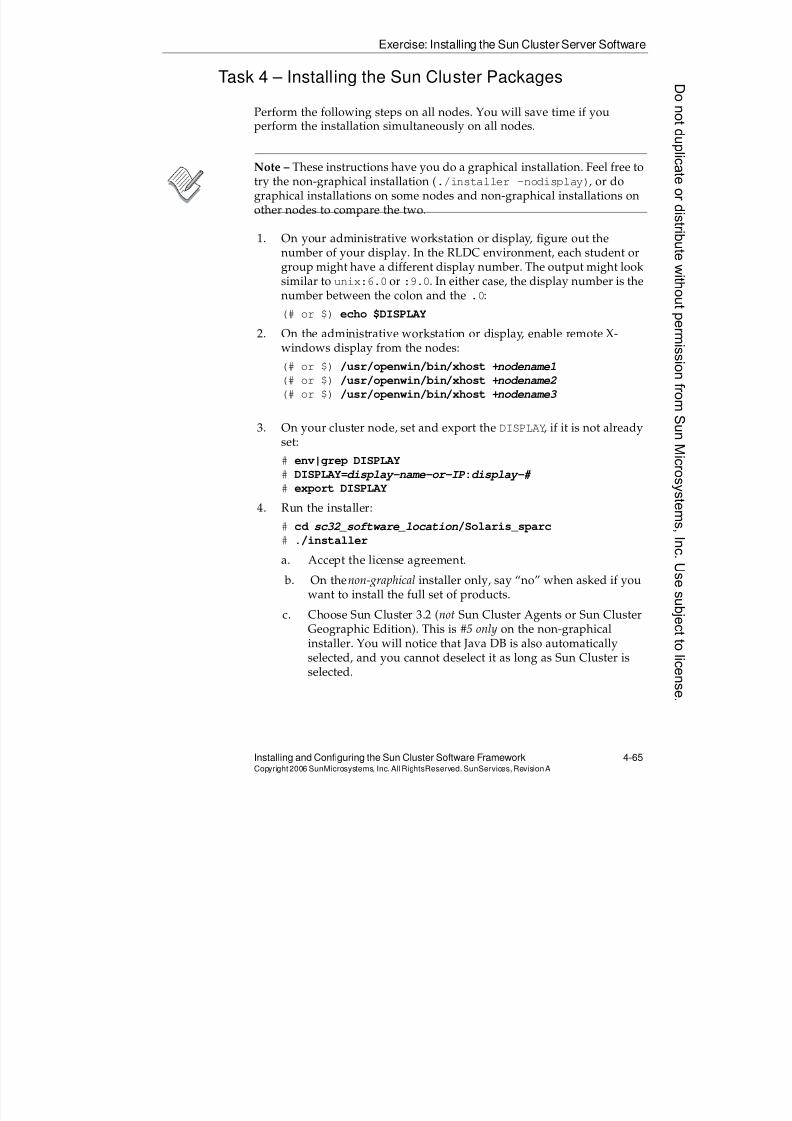
8/4/2019 Sun Cluster 3.2 Administration VC-ES-345
http://slidepdf.com/reader/full/sun-cluster-32-administration-vc-es-345 213/585
8/4/2019 Sun Cluster 3.2 Administration VC-ES-345
http://slidepdf.com/reader/full/sun-cluster-32-administration-vc-es-345 214/585
8/4/2019 Sun Cluster 3.2 Administration VC-ES-345
http://slidepdf.com/reader/full/sun-cluster-32-administration-vc-es-345 215/585
Exercise: Installing the Sun Cluster Server Software
Installing and Configuring the Sun Cluster Software Framework 4-67Copyright2006 SunMicrosystems, Inc. AllRightsReserved. SunServices,RevisionA
/usr/cluster/bin/scdidadm: Could not load DID instance list.
/usr/cluster/bin/scdidadm: Cannot open /etc/cluster/ccr/did_instances.
5. You will observe the following additional error messages every time anode boots into the cluster. They are also normal.
ip: joining multicasts failed (18) on clprivnet0 - will use link layer
broadcasts for multicast
t_optmgmt: System error: Cannot assign requested address
svc.startd[8]: system/cluster/scsymon-srv:default misconfigured
Task 6 – Configuring a New Cluster – The One-Node-at-a-Time Method
If you chose to install your cluster in “Task 5 – Configuring a New Cluster– The All-Nodes-at-Once Method” do not do this task.
Perform the following steps to configure the first node in your cluster (theone that will be assigned node ID 1). You must wait for this node tocomplete and reboot into the cluster before configuring other nodes.
1. Start the scinstall utility (/usr/cluster/bin/scinstall).
2. As the installation proceeds, make the following choices:
a. Choose Option 1 from the Main Menu, Create a new cluster or
add a cluster node. b. Choose Option 2 from the Install Menu, Create just the first
node of a new cluster on this machine.
c. From the Type of Installation Menu, choose Option 1, Typical.
d. Furnish your assigned cluster name.
e. Allow sccheck to run.
f. Furnish the name of the other nodes to be added later.
g. Verify the list of node names.
h. Select the transport adapters. If you are asked (with a taggedVLAN-capable adapter) if it is a dedicated cluster transportadapter, answer Yes.
i. For a two-node cluster, do not disable the automatic quorumselection (answer No).
j. Replyyes to the automatic reboot question.
8/4/2019 Sun Cluster 3.2 Administration VC-ES-345
http://slidepdf.com/reader/full/sun-cluster-32-administration-vc-es-345 216/585
Exercise: Installing the Sun Cluster Server Software
4-68 Sun™ Cluster 3.2 AdministrationCopyright2006 SunMicrosystems, Inc. AllRights Reserved.SunServices,RevisionA
k. Examine the scinstall command options for correctness.Accept them if they seem appropriate.
You must wait for this node to complete rebooting to proceed tothe second node.
3. You will observe the following error messages as the node reboots, just the very first time, into the cluster. They are all normal.
/usr/cluster/bin/scdidadm: Could not load DID instance list.
/usr/cluster/bin/scdidadm: Cannot open /etc/cluster/ccr/did_instances.
4. You will observe the following additional error messages every time anode boots into the cluster. They are also normal.
ip: joining multicasts failed (18) on clprivnet0 - will use link layer
broadcasts for multicast
t_optmgmt: System error: Cannot assign requested address
svc.startd[8]: system/cluster/scsymon-srv:default misconfigured
Perform the following steps on each additional node in the cluster. If youhave more than two nodes, you could perform all the other nodessimultaneously, although then it will be hard to predict which node getswhich node ID. If you want this to be predictable, do one node at a time.
1. Start the scinstall utility on the new node.
2. As the installation proceeds, make the following choices:
a. Choose Option 1 from the Main Menu.
b. Choose Option 3 from the Install Menu, Add this machine as anode in an existing cluster.
c. From the Type of Installation Menu, choose Option 1, Typical.
d. Provide the name of a sponsoring node.
e. Provide the name of the cluster that you want to join.
Type cluster show -t global on the first node (thesponsoring node) if you have forgotten the name of the cluster.
f. Use auto-discovery for the transport adapters.
g. Reply yes to the automatic reboot question.
h. Examine and approve the scinstall command-line options.
i. You will see the same normal boot error messages on theadditional nodes as on the first node.
Donotduplicate
ordistributewithoutpermissionfrom SunMicrosystems,Inc.Usesubject
tolicense.
8/4/2019 Sun Cluster 3.2 Administration VC-ES-345
http://slidepdf.com/reader/full/sun-cluster-32-administration-vc-es-345 217/585
Exercise: Installing the Sun Cluster Server Software
Installing and Configuring the Sun Cluster Software Framework 4-69Copyright2006 SunMicrosystems, Inc. AllRightsReserved. SunServices,RevisionA
Note – You see interconnect-related errors on the existing nodes beginningwhen a new node adds itself to the cluster until the new node completesthe first portion of its reboot operation.
Task 7 – Verifying an Automatically Selected QuorumDevice (Two-Node Cluster)
Perform the following steps to verify automatic quorum selection on atwo-node cluster:
1. In a two node cluster, assuming you have allowed automaticquorum selection, wait after the second node boots until you seeconsole messages (on all nodes) indicating that the quorum device
has been selected.2. On either node, type the clq status command. Verify that your
quorum device was chosen and that you have the expected numberof quorum votes.
8/4/2019 Sun Cluster 3.2 Administration VC-ES-345
http://slidepdf.com/reader/full/sun-cluster-32-administration-vc-es-345 218/585
Exercise: Installing the Sun Cluster Server Software
4-70 Sun™ Cluster 3.2 AdministrationCopyright2006 SunMicrosystems, Inc. AllRights Reserved.SunServices,RevisionA
Task 8 – Configuring a Quorum Device (Three-NodeCluster or Two-Node Cluster With No AutomaticSelection)
Perform the following steps for quorum selection on a three-node cluster:
1. In a three node-cluster, wait after the third node boots until you seeconsole messages (on all nodes) indicating that the quorum votes are being reset.
2. On Node 1, type the cldev list -v command, and record the DIDdevices you intend to configure as quorum disks. For example, if youhad three nodes in a Pair + 1 configuration, you would want twoquorum devices.
Quorum disks: _______ (d4, d6, and so on)
Note – Pay careful attention. The first few DID devices might be localdisks, such as the boot disk and a CD-ROM (target 6). Examine thestandard logical path to make sure the DID device you select is a disk in astorage array and is connected to more than one node.
3. On Node 1, type the clsetup command. Navigate to the section foradding a new quorum device and supply the name of the first DIDdevice (global device) that you selected in the previous step. Youshould see output similar to the following.
clquorum add d12May 3 22:29:13 vincent cl_runtime: NOTICE: CMM:
Cluster members: vincent theo apricot.
May 3 22:29:13 proto192 cl_runtime: NOTICE: CMM: node
reconfiguration #4 completed.
4. If you have three nodes in a Pair +N configuration, you should add asecond quorum device.
5. Reply yes to the reset installmode question (two-node cluster only).
You should see a Cluster initialization is complete message.
6. Type q to quit the clsetup utility.
Donotduplicate
ordistributewithoutpermissionfrom SunMicrosystems,Inc.Usesubject
tolicense.
8/4/2019 Sun Cluster 3.2 Administration VC-ES-345
http://slidepdf.com/reader/full/sun-cluster-32-administration-vc-es-345 219/585

8/4/2019 Sun Cluster 3.2 Administration VC-ES-345
http://slidepdf.com/reader/full/sun-cluster-32-administration-vc-es-345 220/585
8/4/2019 Sun Cluster 3.2 Administration VC-ES-345
http://slidepdf.com/reader/full/sun-cluster-32-administration-vc-es-345 221/585
8/4/2019 Sun Cluster 3.2 Administration VC-ES-345
http://slidepdf.com/reader/full/sun-cluster-32-administration-vc-es-345 222/585
8/4/2019 Sun Cluster 3.2 Administration VC-ES-345
http://slidepdf.com/reader/full/sun-cluster-32-administration-vc-es-345 223/585
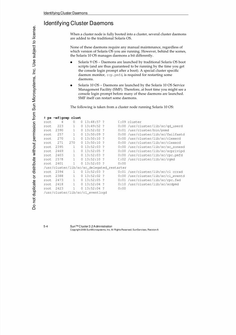
8/4/2019 Sun Cluster 3.2 Administration VC-ES-345
http://slidepdf.com/reader/full/sun-cluster-32-administration-vc-es-345 224/585
Identifying Cluster Daemons
5-4 Sun™Cluster 3 .2AdministrationCopyright2006 SunMicrosystems, Inc. AllRights Reserved.SunServices,RevisionA
Identifying Cluster Daemons
When a cluster node is fully booted into a cluster, several cluster daemonsare added to the traditional Solaris OS.
None of these daemons require any manual maintenance, regardless ofwhich version of Solaris OS you are running. However, behind the scenes,the Solaris 10 OS manages daemons a bit differently.
q Solaris 9 OS – Daemons are launched by traditional Solaris OS bootscripts (and are thus guaranteed to be running by the time you getthe console login prompt after a boot). A special cluster specificdaemon monitor, rcp.pmfd, is required for restarting somedaemons.
q Solaris 10 OS – Daemons are launched by the Solaris 10 OS Service
Management Facility (SMF). Therefore, at boot time you might see aconsole login prompt before many of these daemons are launched.SMF itself can restart some daemons.
The following is taken from a cluster node running Solaris 10 OS:
# ps -ef|grep clust
root 4 0 0 13:48:57 ? 0:09 cluster
root 223 1 0 13:49:52 ? 0:00 /usr/cluster/lib/sc/qd_userd
root 2390 1 0 13:52:02 ? 0:01 /usr/cluster/bin/pnmd
root 257 1 0 13:50:09 ? 0:00 /usr/cluster/lib/sc/failfastdroot 270 1 0 13:50:10 ? 0:00 /usr/cluster/lib/sc/clexecd
root 271 270 0 13:50:10 ? 0:00 /usr/cluster/lib/sc/clexecd
root 2395 1 0 13:52:03 ? 0:00 /usr/cluster/lib/sc/sc_zonesd
root 2469 1 0 13:52:05 ? 0:00 /usr/cluster/lib/sc/scprivipd
root 2403 1 0 13:52:03 ? 0:00 /usr/cluster/lib/sc/rpc.pmfd
root 2578 1 0 13:52:10 ? 0:02 /usr/cluster/lib/sc/rgmd
root 2401 1 0 13:52:03 ? 0:00
/usr/cluster/lib/sc/sc_delegated_restarter
root 2394 1 0 13:52:03 ? 0:01 /usr/cluster/lib/sc/cl_ccrad
root 2388 1 0 13:52:02 ? 0:00 /usr/cluster/lib/sc/cl_eventd
root 2473 1 0 13:52:05 ? 0:01 /usr/cluster/lib/sc/rpc.fedroot 2418 1 0 13:52:04 ? 0:10 /usr/cluster/lib/sc/scdpmd
root 2423 1 0 13:52:04 ? 0:00
/usr/cluster/lib/sc/cl_eventlogd
Donotduplicate
ordistributewithoutpermissionfrom SunMicrosystems,Inc.Usesubject
tolicense.
8/4/2019 Sun Cluster 3.2 Administration VC-ES-345
http://slidepdf.com/reader/full/sun-cluster-32-administration-vc-es-345 225/585
Identifying Cluster Daemons
Performing Basic Cluster Administration 5-5Copyright2006 SunMicrosystems, Inc. AllRightsReserved. SunServices,RevisionA
q cluster – This is a system process (created by the kernel) toencapsulate the kernel threads that make up the core kernel range ofoperations.
There is no way to kill this process (even with a KILL signal) becauseit is always in the kernel.
q failfastd – This daemon is the failfast proxy server. Otherdaemons that require services of the failfast device driver registerwith failfastd. The failfast daemon allows the kernel to panic ifcertain essential daemons have failed.
q clexecd – This is used by cluster kernel threads to executeuserland commands (such as the run_reserve and dofsck
commands). It is also used to run cluster commands remotely (likethe cluster shutdown command).
This daemon registers with failfastd so that a failfast device driver
will panic the kernel if this daemon is killed and not restarted in 30seconds.
q cl_eventd – This daemon registers and forwards cluster events(such as nodes entering and leaving the cluster). There is also aprotocol whereby user applications can register themselves to receivecluster events.
The daemon is automatically respawned if it is killed.
q qd_userd – This daemon serves as a proxy whenever any quorumdevice activity requires execution of some command in userland (forexample, a NAS quorum device).
If you kill this daemon, you must restart it manually.
q rgmd – This is the resource group manager, which manages the stateof all cluster-unaware applications.
A failfast driver panics the kernel if this daemon is killed and notrestarted in 30 seconds.
q rpc.fed – This is the fork-and-exec daemon, which handles requestsfrom rgmd to spawn methods for specific data services.
A failfast driver panics the kernel if this daemon is killed and not
restarted in 30 seconds.q rpc.pmfd – This is the process monitoring facility. It is used as a
general mechanism to initiate restarts and failure action scripts forsome cluster framework daemons (in Solaris 9 OS), and for mostapplication daemons and application fault monitors (in Solaris 9 and10 OS)
8/4/2019 Sun Cluster 3.2 Administration VC-ES-345
http://slidepdf.com/reader/full/sun-cluster-32-administration-vc-es-345 226/585
Identifying Cluster Daemons
5-6 Sun™Cluster 3 .2AdministrationCopyright2006 SunMicrosystems, Inc. AllRights Reserved.SunServices,RevisionA
A failfast driver panics the kernel if this daemon is stopped andnot restarted in 30 seconds.
q pnmd – This is the public network management daemon, whichmanages network status information received from the local IPMPdaemon running on each node and facilitates application failovers
caused by complete public network failures on nodes.
It is automatically restarted if it is stopped.
q cl_eventlogd – This daemon logs cluster events into a binary logfile. At the time of writing for this course, there is no publishedinterface to this log.
It is automatically restarted if it is stopped.
q cl_ccrad – This daemon provides access from userlandmanagement applications to the CCR.
It is automatically restarted if it is stopped.q scdpmd – This daemon monitors the status of disk paths, so that
they can be reported in the output of the cldev status command.
It is automatically restarted if it is stopped.
q sc_zonesd – This daemon monitors the state of Solaris 10 non-globalzones so that applications designed to failover between zones canreact appropriately to zone booting and failure.
A failfast driver panics the kernel if this daemon is stopped andnot restarted in 30 seconds.
q sc_delegated_restarter – This daemon restarts clusterapplications that are written as SMF services and then placed undercontrol of the cluster using the Sun Cluster 3.2 SMF proxy feature.
It is automatically restarted if it is stopped.
q scprivipd – This daemon provisions IP addresses on theclprivnet0 interface, on behalf of zones.
It is automatically restarted if it is stopped.
Donotduplicate
ordistributewithoutpermissionfrom SunMicrosystems,Inc.Usesubject
tolicense.
8/4/2019 Sun Cluster 3.2 Administration VC-ES-345
http://slidepdf.com/reader/full/sun-cluster-32-administration-vc-es-345 227/585
Using Cluster Commands
Performing Basic Cluster Administration 5-7Copyright2006 SunMicrosystems, Inc. AllRightsReserved. SunServices,RevisionA
Using Cluster Commands
The Sun Cluster 3.2 command-line commands have an object-orientednature. That is:
q The name of the command is related to the cluster object you aretrying to display or administer.
q Every command requires a sub-command that indicates what it is youactually want to do.
q Every command has a common style of syntax whereby:
q When using sub-commands to operate on (or delete) a specificobject, you give the name of the object as the last item on thecommand line, or you give a + to indicate a wildcard. Thewildcard might still be limited by other command-line
arguments (specific group or subtypes, if appropriate).q When using subcommands to display configuration or status,
the default is to show all objects (of that category), but you cangive an optional last argument to show only a specific object.
Commands Relating to Basic Cluster Administration
The following commands are presented in more detail in this module because they relate to configuration, status, or administration that is
useful at this point in the course. Every command has a full name. Somecommands have an abbreviated name (long and short names hard linkedto the same executable):
q clnode – Configuration, status, and settings for nodes
q clquorum (clq) – Configuration, status, settings, adding, anddeleting quorum devices (includes node quorum information)
q clinterconnect (clintr) – Configuration, status, settings, adding,and deleting private networks
q cldevice (cldev) – Configuration, status, and settings for
individual devices (disk, CDROM, and tape)q cluster:
q Administering cluster global settings
q Showing configuration and status of everything; can be limited by other arguments to certain types or groups of information
8/4/2019 Sun Cluster 3.2 Administration VC-ES-345
http://slidepdf.com/reader/full/sun-cluster-32-administration-vc-es-345 228/585
8/4/2019 Sun Cluster 3.2 Administration VC-ES-345
http://slidepdf.com/reader/full/sun-cluster-32-administration-vc-es-345 229/585
8/4/2019 Sun Cluster 3.2 Administration VC-ES-345
http://slidepdf.com/reader/full/sun-cluster-32-administration-vc-es-345 230/585
8/4/2019 Sun Cluster 3.2 Administration VC-ES-345
http://slidepdf.com/reader/full/sun-cluster-32-administration-vc-es-345 231/585
8/4/2019 Sun Cluster 3.2 Administration VC-ES-345
http://slidepdf.com/reader/full/sun-cluster-32-administration-vc-es-345 232/585
Viewing and Administering Nodes
5-12 Sun™ Cluster 3.2 AdministrationCopyright2006 SunMicrosystems, Inc. AllRights Reserved.SunServices,RevisionA
Viewing and Administering Nodes
The clnode command can be used to show status and configuration ofnodes. While it shows a variety of data for each node in the cluster, thereis only a limited amount that you can actually change with the clnode
command.
Viewing Node Status and Configuration
The status and show sub-commands show, by default, all nodes. Youcould also show a single node by giving its name as the last command-line argument:
# clnode status
Cluster Nodes ===
--- Node Status ---
Node Name Status
--------- ------
vincent Online
theo Online
# clnode show
Cluster Nodes ===
Node Name: vincent
Node ID: 1
Enabled: yes
privatehostname: clusternode1-priv
reboot_on_path_failure: disabled
globalzoneshares: 1
defaultpsetmin: 1
quorum_vote: 1
quorum_defaultvote: 1
quorum_resv_key: 0x44A1995C00000001
Transport Adapter List: hme0, qfe0
Node Name: theo
Node ID: 2
Enabled: yes
privatehostname: clusternode2-privDonotduplicate
ordistributewithoutpermissionfrom SunMicrosystems,Inc.Usesubject
tolicense.
8/4/2019 Sun Cluster 3.2 Administration VC-ES-345
http://slidepdf.com/reader/full/sun-cluster-32-administration-vc-es-345 233/585
Viewing and Administering Nodes
Performing Basic Cluster Administration 5-13Copyright2006 SunMicrosystems, Inc. AllRightsReserved. SunServices,RevisionA
reboot_on_path_failure: disabled
globalzoneshares: 1
defaultpsetmin: 1
quorum_vote: 1
quorum_defaultvote: 1
quorum_resv_key: 0x44A1995C00000002
Transport Adapter List: hme0, qfe0
Modifying Node Information
Most of the information shown by clnode show cannot be modified bythe clnode command. Some can be modified by other commands(clinterconnect for adding and deleting transport adapters, forexample).
The reboot_on_path_failure command is described later in themodule.
You could set the privatehostname to whatever you want. This nameautomatically resolves to the IP address associated with the node’sclprivnet0 adapter. This is the single private IP address whose traffic isautomatically distributed across all physical private networks.
# clnode set -p privatehostname=vinny-priv vincent
# clnode show vincent
Cluster Nodes ===
Node Name: vincent
Node ID: 1
Enabled: yes
privatehostname: vinny-priv
reboot_on_path_failure: disabled
globalzoneshares: 1
defaultpsetmin: 1
quorum_vote: 1
quorum_defaultvote: 1
quorum_resv_key: 0x44A1995C00000001Transport Adapter List: hme0, qfe0
# getent hosts vinny-priv
172.16.4.1 vinny-priv
# clnode set -p privatehostname=clusternode1-priv vincent
8/4/2019 Sun Cluster 3.2 Administration VC-ES-345
http://slidepdf.com/reader/full/sun-cluster-32-administration-vc-es-345 234/585
Viewing and Administering Nodes
5-14 Sun™ Cluster 3.2 AdministrationCopyright2006 SunMicrosystems, Inc. AllRights Reserved.SunServices,RevisionA
Note – If it seems that the OS can resolve private hostnames that nolonger exist (because you changed them), it is because of the OS name-caching daemon (nscd). You can use nscd -i hosts to clear this cache.
Viewing Software Release Information on a Node
You can use clnode show-rev -v to see installed cluster package releaseinformation on a node, or on all nodes. This is useful information to havewhen talking to technical support personnel.
# clnode show-rev -v
Sun Cluster 3.2 for Solaris 10 sparc
SUNWscr: 3.2.0,REV=2006.06.20.21.39
SUNWscu: 3.2.0,REV=2006.06.20.21.39
SUNWscrtlh: 3.2.0,REV=2006.06.20.21.39SUNWsccomu: 3.2.0,REV=2006.06.20.21.39
SUNWsczr: 3.2.0,REV=2006.06.20.21.39
SUNWsccomzu: 3.2.0,REV=2006.06.20.21.39
SUNWsczu: 3.2.0,REV=2006.06.20.21.39
SUNWscsckr: 3.2.0,REV=2006.06.20.21.39
SUNWscscku: 3.2.0,REV=2006.06.20.21.39
SUNWscnmr: 3.2.0,REV=2006.06.20.21.39
SUNWscnmu: 3.2.0,REV=2006.06.20.21.39
SUNWscdev: 3.2.0,REV=2006.06.20.21.39
SUNWscgds: 3.2.0,REV=2006.06.20.21.39
SUNWscsmf: 3.2.0,REV=2006.06.20.21.39SUNWscman: 3.2.0,REV=2006.06.13.11.24
SUNWscsal: 3.2.0,REV=2006.06.20.21.39
SUNWscsam: 3.2.0,REV=2006.06.20.21.39
SUNWscvm: 3.2.0,REV=2006.06.20.21.39
SUNWmdmr: 3.2.0,REV=2006.06.20.21.39
SUNWmdmu: 3.2.0,REV=2006.06.20.21.39
SUNWscmasa: 3.2.0,REV=2006.06.20.21.39
SUNWscmasar: 3.2.0,REV=2006.06.20.21.39
SUNWscmasasen: 3.2.0,REV=2006.06.20.21.39
SUNWscmasau: 3.2.0,REV=2006.06.20.21.39
SUNWscmautil: 3.2.0,REV=2006.06.20.21.39
SUNWscmautilr: 3.2.0,REV=2006.06.20.21.39
SUNWjfreechart: 3.2.0,REV=2006.06.20.21.39
SUNWscspmu: 3.2.0,REV=2006.06.20.21.39
SUNWscderby: 3.2.0,REV=2006.06.20.21.39
SUNWsctelemetry: 3.2.0,REV=2006.06.20.21.39
Donotduplicate
ordistributewithoutpermissionfrom SunMicrosystems,Inc.Usesubject
tolicense.
8/4/2019 Sun Cluster 3.2 Administration VC-ES-345
http://slidepdf.com/reader/full/sun-cluster-32-administration-vc-es-345 235/585
Viewing and Administering Nodes
Performing Basic Cluster Administration 5-15Copyright2006 SunMicrosystems, Inc. AllRightsReserved. SunServices,RevisionA
You can also directly examine the file /etc/cluster/release to getquick information about the release of the cluster software installed on aparticular node:
# cat /etc/cluster/release
Sun Cluster 3.2 for Solaris 10 sparc
Copyright 2006 Sun Microsystems, Inc. All Rights Reserved.
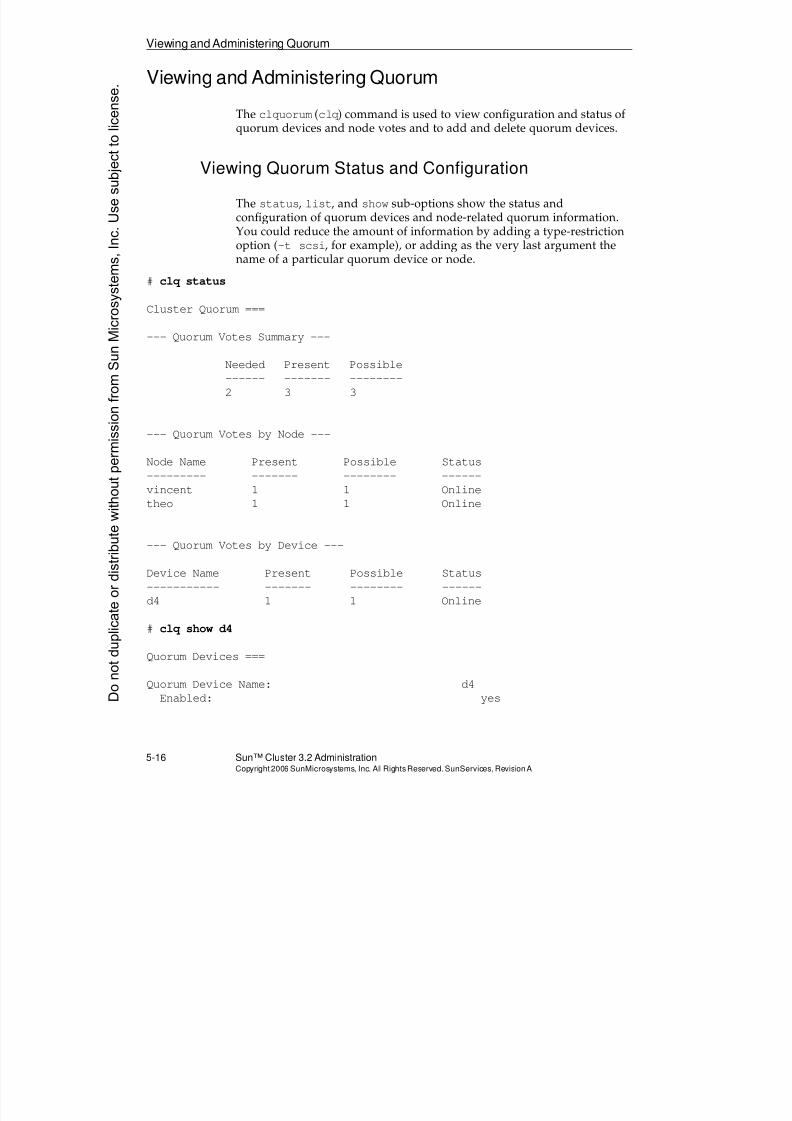
8/4/2019 Sun Cluster 3.2 Administration VC-ES-345
http://slidepdf.com/reader/full/sun-cluster-32-administration-vc-es-345 236/585
Viewing and Administering Quorum
5-16 Sun™ Cluster 3.2 AdministrationCopyright2006 SunMicrosystems, Inc. AllRights Reserved.SunServices,RevisionA
Viewing and Administering Quorum
The clquorum (clq) command is used to view configuration and status ofquorum devices and node votes and to add and delete quorum devices.
Viewing Quorum Status and Configuration
The status, list, and show sub-options show the status andconfiguration of quorum devices and node-related quorum information.You could reduce the amount of information by adding a type-restrictionoption (-t scsi, for example), or adding as the very last argument thename of a particular quorum device or node.
# clq status
Cluster Quorum ===
--- Quorum Votes Summary ---
Needed Present Possible
------ ------- --------
2 3 3
--- Quorum Votes by Node ---
Node Name Present Possible Status
--------- ------- -------- ------
vincent 1 1 Online
theo 1 1 Online
--- Quorum Votes by Device ---
Device Name Present Possible Status
----------- ------- -------- ------
d4 1 1 Online
# clq show d4
Quorum Devices ===
Quorum Device Name: d4
Enabled: yesDonotduplicate
ordistributewithoutpermissionfrom SunMicrosystems,Inc.Usesubject
tolicense.
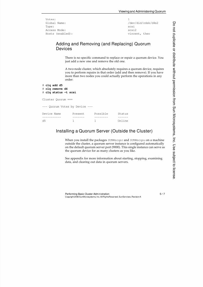
8/4/2019 Sun Cluster 3.2 Administration VC-ES-345
http://slidepdf.com/reader/full/sun-cluster-32-administration-vc-es-345 237/585
Viewing and Administering Quorum
Performing Basic Cluster Administration 5-17Copyright2006 SunMicrosystems, Inc. AllRightsReserved. SunServices,RevisionA
Votes: 1
Global Name: /dev/did/rdsk/d4s2
Type: scsi
Access Mode: scsi2
Hosts (enabled): vincent, theo
Adding and Removing (and Replacing) QuorumDevices
There is no specific command to replace or repair a quorum device. You just add a new one and remove the old one.
A two-node cluster, which absolutely requires a quorum device, requiresyou to perform repairs in that order (add and then remove). If you have
more than two nodes you could actually perform the operations in anyorder:
# clq add d5
# clq remove d4
# clq status -t scsi
Cluster Quorum ===
--- Quorum Votes by Device ---
Device Name Present Possible Status
----------- ------- -------- ------d5 1 1 Online
Installing a Quorum Server (Outside the Cluster)
When you install the packages SUNWscqsr and SUNWscqsu on a machineoutside the cluster, a quorum server instance is configured automaticallyon the default quorum server port (9000). This single instance can serve asthe quorum device for as many clusters as you like.
See appendix for more information about starting, stopping, examiningdata, and clearing out data in quorum servers.
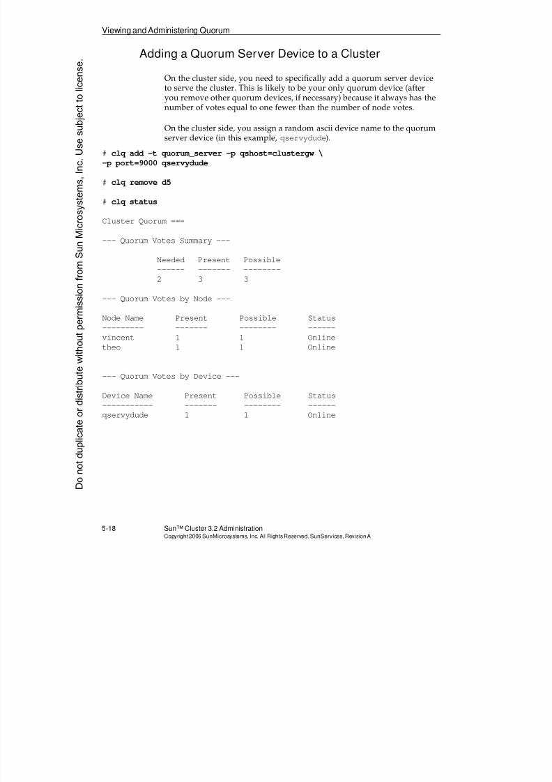
8/4/2019 Sun Cluster 3.2 Administration VC-ES-345
http://slidepdf.com/reader/full/sun-cluster-32-administration-vc-es-345 238/585
Viewing and Administering Quorum
5-18 Sun™ Cluster 3.2 AdministrationCopyright2006 SunMicrosystems, Inc. AllRights Reserved.SunServices,RevisionA
Adding a Quorum Server Device to a Cluster
On the cluster side, you need to specifically add a quorum server deviceto serve the cluster. This is likely to be your only quorum device (afteryou remove other quorum devices, if necessary) because it always has the
number of votes equal to one fewer than the number of node votes.
On the cluster side, you assign a random ascii device name to the quorumserver device (in this example, qservydude).
# clq add -t quorum_server -p qshost=clustergw \
-p port=9000 qservydude
# clq remove d5
# clq status
Cluster Quorum ===
--- Quorum Votes Summary ---
Needed Present Possible
------ ------- --------
2 3 3
--- Quorum Votes by Node ---
Node Name Present Possible Status--------- ------- -------- ------
vincent 1 1 Online
theo 1 1 Online
--- Quorum Votes by Device ---
Device Name Present Possible Status
----------- ------- -------- ------
qservydude 1 1 Online
Donotduplicate
ordistributewithoutpermissionfrom SunMicrosystems,Inc.Usesubject
tolicense.
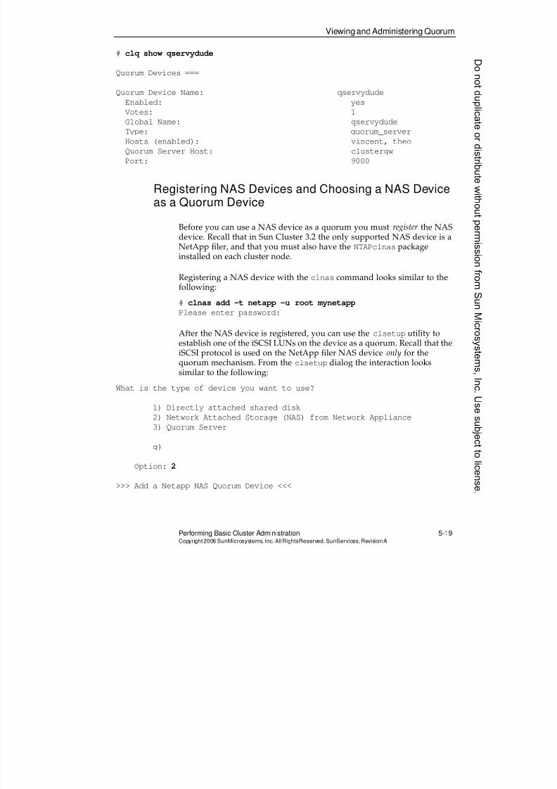
8/4/2019 Sun Cluster 3.2 Administration VC-ES-345
http://slidepdf.com/reader/full/sun-cluster-32-administration-vc-es-345 239/585
Viewing and Administering Quorum
Performing Basic Cluster Administration 5-19Copyright2006 SunMicrosystems, Inc. AllRightsReserved. SunServices,RevisionA
# clq show qservydude
Quorum Devices ===
Quorum Device Name: qservydude
Enabled: yes
Votes: 1
Global Name: qservydude
Type: quorum_server
Hosts (enabled): vincent, theo
Quorum Server Host: clustergw
Port: 9000
Registering NAS Devices and Choosing a NAS Deviceas a Quorum Device
Before you can use a NAS device as a quorum you must register the NASdevice. Recall that in Sun Cluster 3.2 the only supported NAS device is aNetApp filer, and that you must also have the NTAPclnas packageinstalled on each cluster node.
Registering a NAS device with the clnas command looks similar to thefollowing:
# clnas add -t netapp -u root mynetapp
Please enter password:
After the NAS device is registered, you can use the clsetup utility toestablish one of the iSCSI LUNs on the device as a quorum. Recall that theiSCSI protocol is used on the NetApp filer NAS device only for thequorum mechanism. From the clsetup dialog the interaction lookssimilar to the following:
What is the type of device you want to use?
1) Directly attached shared disk
2) Network Attached Storage (NAS) from Network Appliance
3) Quorum Server
q)
Option: 2
>>> Add a Netapp NAS Quorum Device <<<
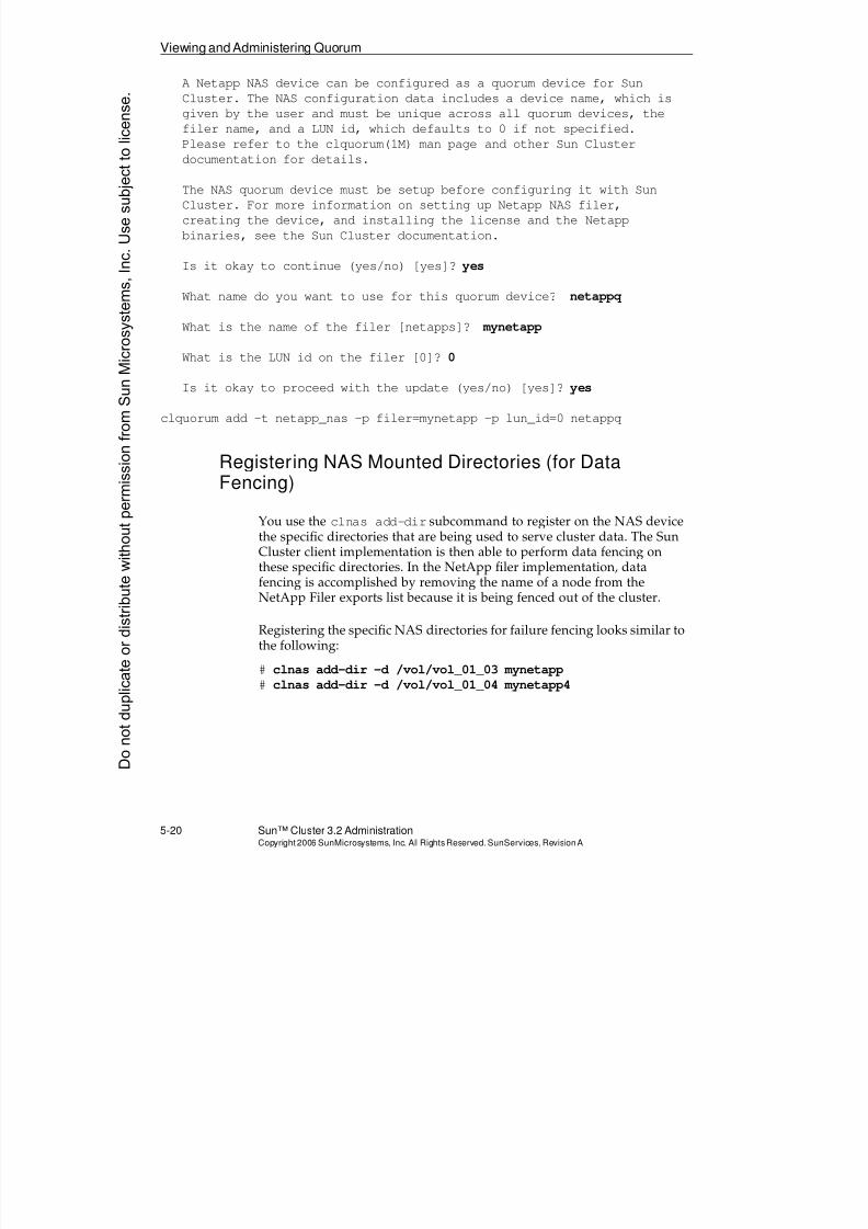
8/4/2019 Sun Cluster 3.2 Administration VC-ES-345
http://slidepdf.com/reader/full/sun-cluster-32-administration-vc-es-345 240/585
Viewing and Administering Quorum
5-20 Sun™ Cluster 3.2 AdministrationCopyright2006 SunMicrosystems, Inc. AllRights Reserved.SunServices,RevisionA
A Netapp NAS device can be configured as a quorum device for Sun
Cluster. The NAS configuration data includes a device name, which is
given by the user and must be unique across all quorum devices, the
filer name, and a LUN id, which defaults to 0 if not specified.
Please refer to the clquorum(1M) man page and other Sun Cluster
documentation for details.
The NAS quorum device must be setup before configuring it with Sun
Cluster. For more information on setting up Netapp NAS filer,
creating the device, and installing the license and the Netapp
binaries, see the Sun Cluster documentation.
Is it okay to continue (yes/no) [yes]? yes
What name do you want to use for this quorum device? netappq
What is the name of the filer [netapps]? mynetapp
What is the LUN id on the filer [0]? 0
Is it okay to proceed with the update (yes/no) [yes]? yes
clquorum add -t netapp_nas -p filer=mynetapp -p lun_id=0 netappq
Registering NAS Mounted Directories (for DataFencing)
You use the clnas add-dir subcommand to register on the NAS devicethe specific directories that are being used to serve cluster data. The SunCluster client implementation is then able to perform data fencing onthese specific directories. In the NetApp filer implementation, datafencing is accomplished by removing the name of a node from theNetApp Filer exports list because it is being fenced out of the cluster.
Registering the specific NAS directories for failure fencing looks similar tothe following:
# clnas add-dir -d /vol/vol_01_03 mynetapp# clnas add-dir -d /vol/vol_01_04 mynetapp4
Donotduplicate
ordistributewithoutpermissionfrom SunMicrosystems,Inc.Usesubject
tolicense.
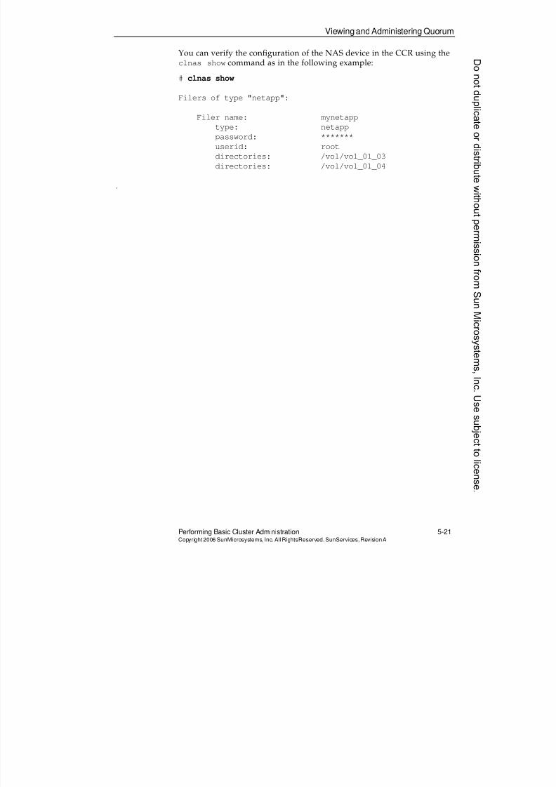
8/4/2019 Sun Cluster 3.2 Administration VC-ES-345
http://slidepdf.com/reader/full/sun-cluster-32-administration-vc-es-345 241/585
Viewing and Administering Quorum
Performing Basic Cluster Administration 5-21Copyright2006 SunMicrosystems, Inc. AllRightsReserved. SunServices,RevisionA
You can verify the configuration of the NAS device in the CCR using theclnas show command as in the following example:
# clnas show
Filers of type "netapp":
Filer name: mynetapp
type: netapp
password: *******
userid: root
directories: /vol/vol_01_03
directories: /vol/vol_01_04
.
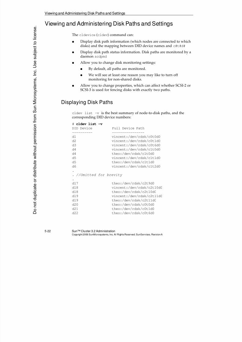
8/4/2019 Sun Cluster 3.2 Administration VC-ES-345
http://slidepdf.com/reader/full/sun-cluster-32-administration-vc-es-345 242/585
Viewing and Administering Disk Paths and Settings
5-22 Sun™ Cluster 3.2 AdministrationCopyright2006 SunMicrosystems, Inc. AllRights Reserved.SunServices,RevisionA
Viewing and Administering Disk Paths and Settings
The cldevice (cldev) command can:
q Display disk path information (which nodes are connected to which
disks) and the mapping between DID device names and c#t#d#
q Display disk path status information. Disk paths are monitored by adaemon scdpmd
q Allow you to change disk monitoring settings:
q By default, all paths are monitored.
q We will see at least one reason you may like to turn offmonitoring for non-shared disks.
q Allow you to change properties, which can affect whether SCSI-2 orSCSI-3 is used for fencing disks with exactly two paths.
Displaying Disk Paths
cldev list -v is the best summary of node-to-disk paths, and thecorresponding DID device numbers:
# cldev list -v
DID Device Full Device Path
---------- ----------------
d1 vincent:/dev/rdsk/c0t0d0
d2 vincent:/dev/rdsk/c0t1d0
d3 vincent:/dev/rdsk/c0t6d0
d4 vincent:/dev/rdsk/c1t0d0
d4 theo:/dev/rdsk/c1t0d0
d5 vincent:/dev/rdsk/c1t1d0
d5 theo:/dev/rdsk/c1t1d0
d6 vincent:/dev/rdsk/c1t2d0
.
. //Omitted for brevity
.
d17 theo:/dev/rdsk/c2t9d0
d18 vincent:/dev/rdsk/c2t10d0
d18 theo:/dev/rdsk/c2t10d0
d19 vincent:/dev/rdsk/c2t11d0
d19 theo:/dev/rdsk/c2t11d0
d20 theo:/dev/rdsk/c0t0d0
d21 theo:/dev/rdsk/c0t1d0
d22 theo:/dev/rdsk/c0t6d0Donotduplicate
ordistributewithoutpermissionfrom SunMicrosystems,Inc.Usesubject
tolicense.
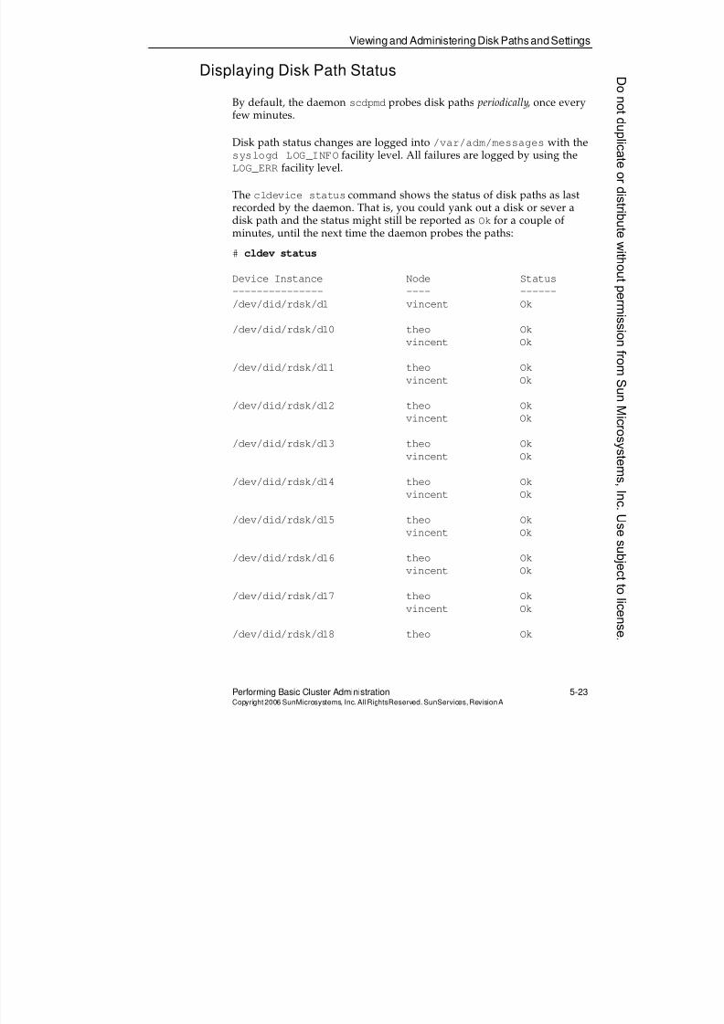
8/4/2019 Sun Cluster 3.2 Administration VC-ES-345
http://slidepdf.com/reader/full/sun-cluster-32-administration-vc-es-345 243/585
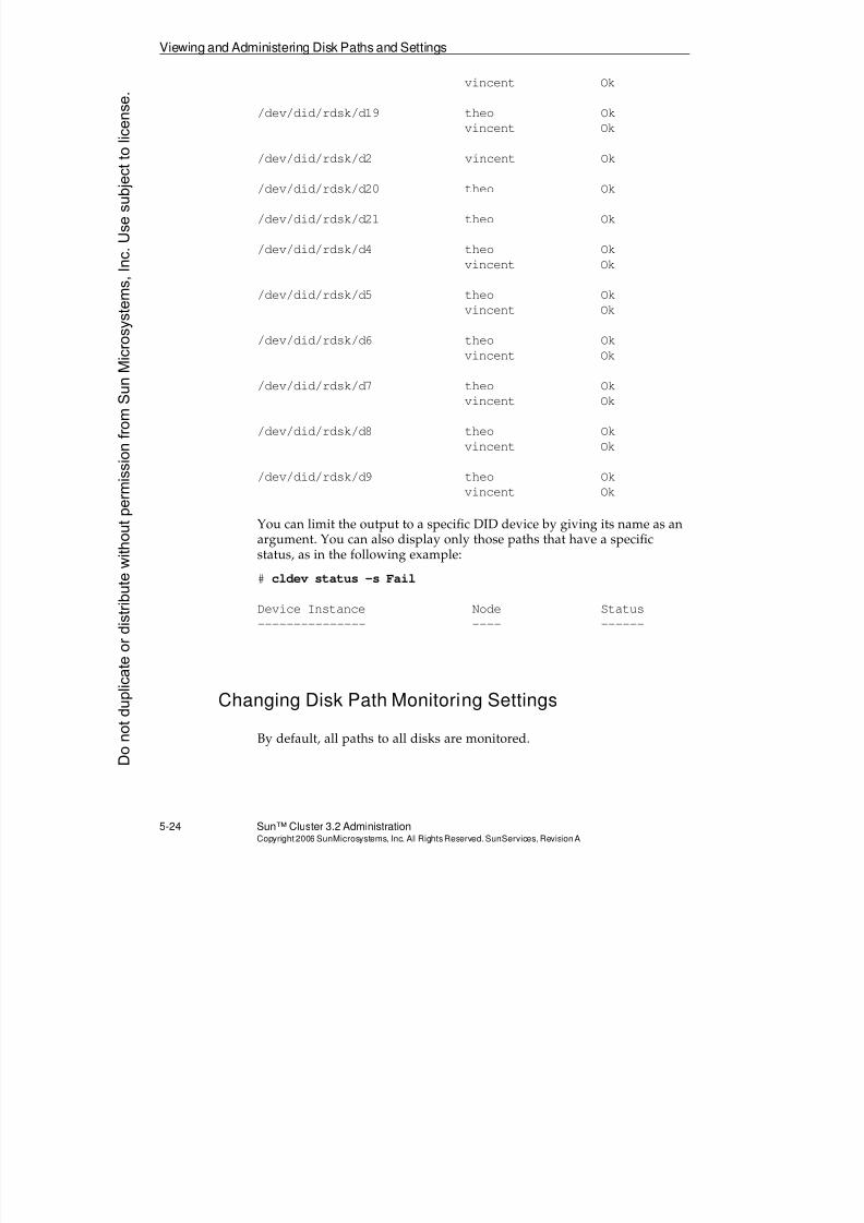
8/4/2019 Sun Cluster 3.2 Administration VC-ES-345
http://slidepdf.com/reader/full/sun-cluster-32-administration-vc-es-345 244/585
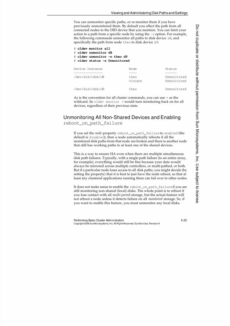
8/4/2019 Sun Cluster 3.2 Administration VC-ES-345
http://slidepdf.com/reader/full/sun-cluster-32-administration-vc-es-345 245/585
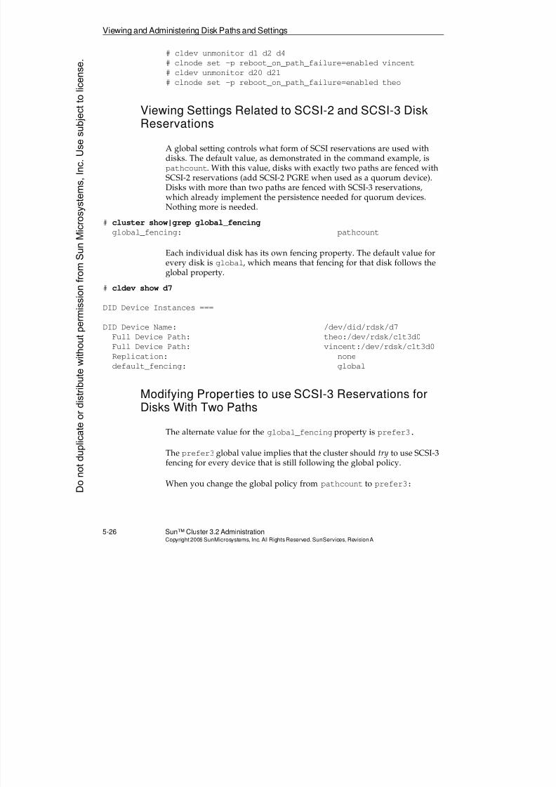
8/4/2019 Sun Cluster 3.2 Administration VC-ES-345
http://slidepdf.com/reader/full/sun-cluster-32-administration-vc-es-345 246/585
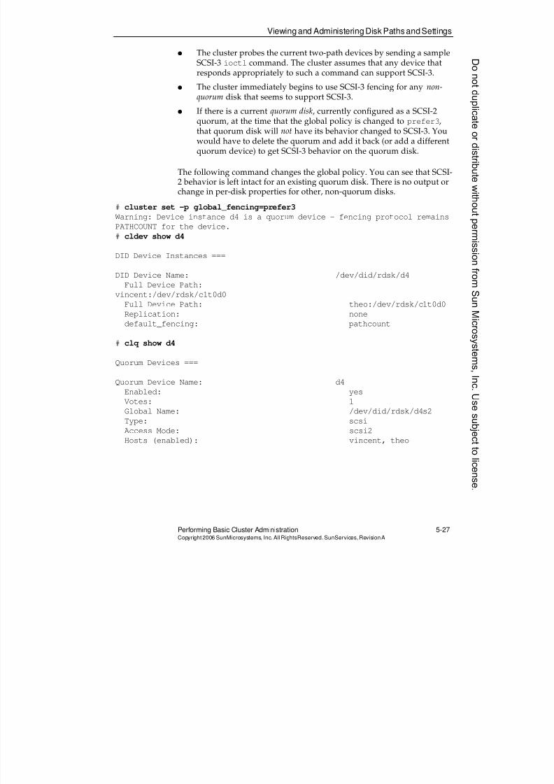
8/4/2019 Sun Cluster 3.2 Administration VC-ES-345
http://slidepdf.com/reader/full/sun-cluster-32-administration-vc-es-345 247/585
8/4/2019 Sun Cluster 3.2 Administration VC-ES-345
http://slidepdf.com/reader/full/sun-cluster-32-administration-vc-es-345 248/585
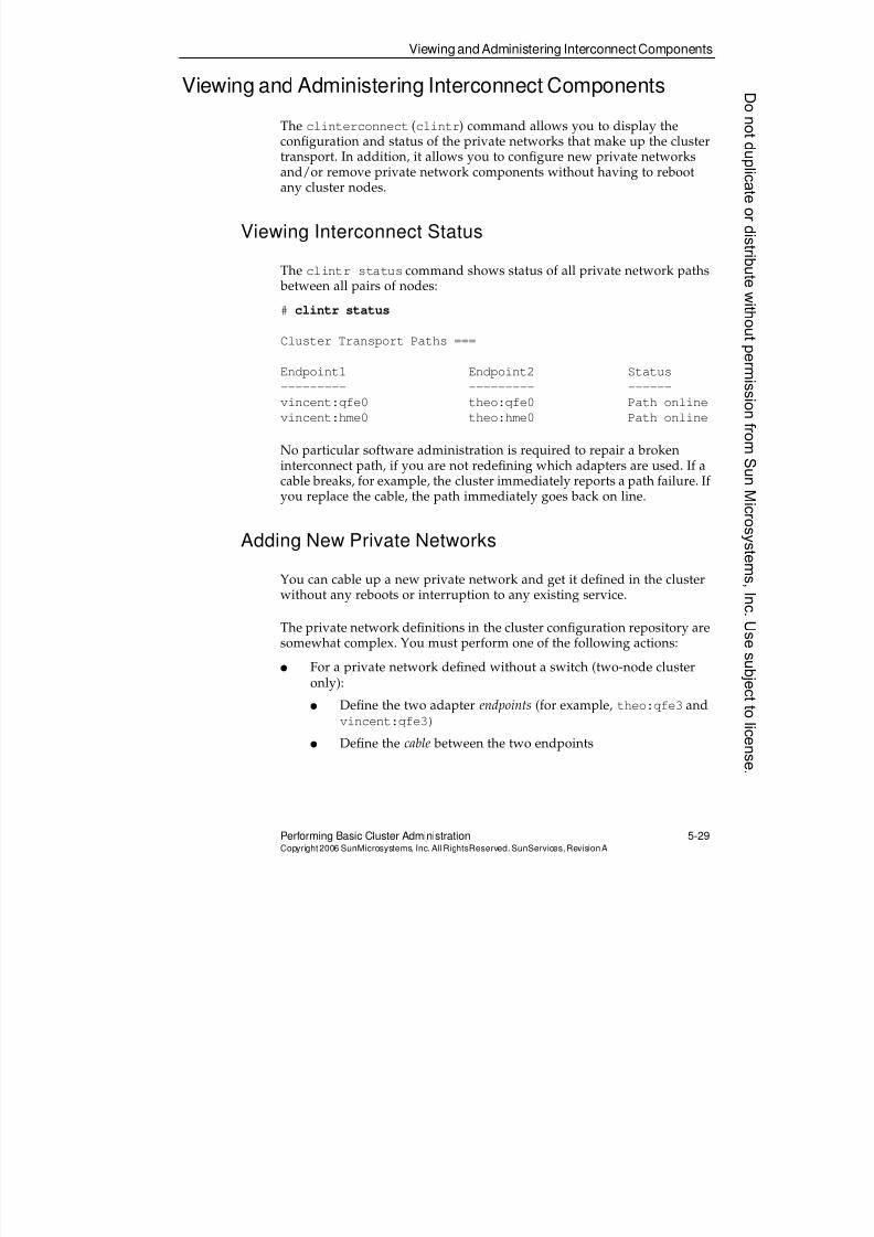
8/4/2019 Sun Cluster 3.2 Administration VC-ES-345
http://slidepdf.com/reader/full/sun-cluster-32-administration-vc-es-345 249/585
Viewing and Administering Interconnect Components
Performing Basic Cluster Administration 5-29Copyright2006 SunMicrosystems, Inc. AllRightsReserved. SunServices,RevisionA
Viewing and Administering Interconnect Components
The clinterconnect (clintr) command allows you to display theconfiguration and status of the private networks that make up the clustertransport. In addition, it allows you to configure new private networksand/or remove private network components without having to rebootany cluster nodes.
Viewing Interconnect Status
The clintr status command shows status of all private network paths between all pairs of nodes:
# clintr status
Cluster Transport Paths ===
Endpoint1 Endpoint2 Status
--------- --------- ------
vincent:qfe0 theo:qfe0 Path online
vincent:hme0 theo:hme0 Path online
No particular software administration is required to repair a brokeninterconnect path, if you are not redefining which adapters are used. If acable breaks, for example, the cluster immediately reports a path failure. If
you replace the cable, the path immediately goes back on line.
Adding New Private Networks
You can cable up a new private network and get it defined in the clusterwithout any reboots or interruption to any existing service.
The private network definitions in the cluster configuration repository aresomewhat complex. You must perform one of the following actions:
q For a private network defined without a switch (two-node clusteronly):
q Define the two adapter endpoints (for example, theo:qfe3 andvincent:qfe3)
q Define the cable between the two endpoints
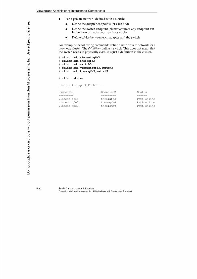
8/4/2019 Sun Cluster 3.2 Administration VC-ES-345
http://slidepdf.com/reader/full/sun-cluster-32-administration-vc-es-345 250/585
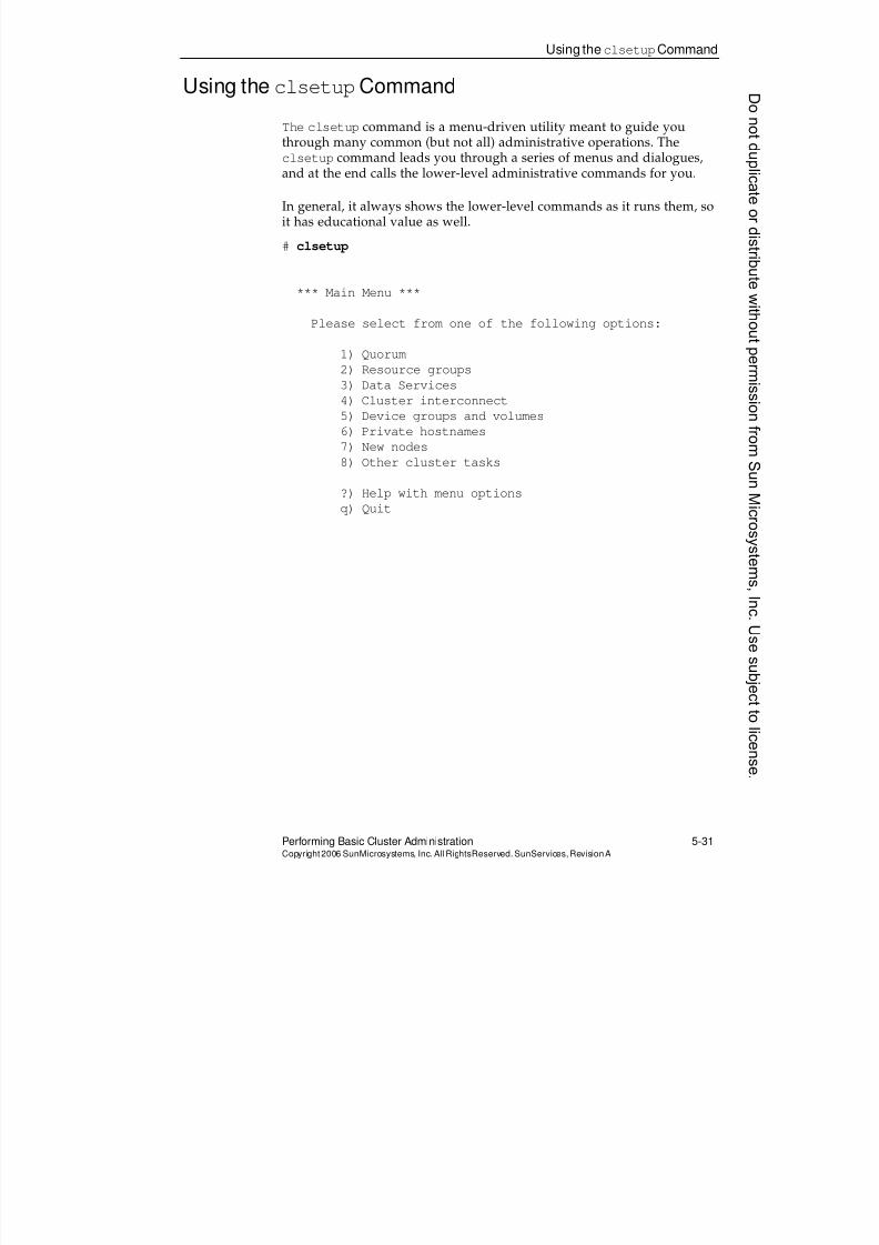
8/4/2019 Sun Cluster 3.2 Administration VC-ES-345
http://slidepdf.com/reader/full/sun-cluster-32-administration-vc-es-345 251/585
Using theclsetupCommand
Performing Basic Cluster Administration 5-31Copyright2006 SunMicrosystems, Inc. AllRightsReserved. SunServices,RevisionA
Using the clsetupCommand
The clsetup command is a menu-driven utility meant to guide youthrough many common (but not all) administrative operations. Theclsetup command leads you through a series of menus and dialogues,and at the end calls the lower-level administrative commands for you.
In general, it always shows the lower-level commands as it runs them, soit has educational value as well.
# clsetup
*** Main Menu ***
Please select from one of the following options:
1) Quorum
2) Resource groups
3) Data Services
4) Cluster interconnect
5) Device groups and volumes
6) Private hostnames
7) New nodes
8) Other cluster tasks
?) Help with menu options
q) Quit
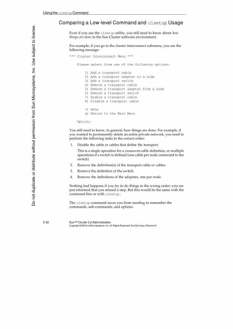
8/4/2019 Sun Cluster 3.2 Administration VC-ES-345
http://slidepdf.com/reader/full/sun-cluster-32-administration-vc-es-345 252/585
8/4/2019 Sun Cluster 3.2 Administration VC-ES-345
http://slidepdf.com/reader/full/sun-cluster-32-administration-vc-es-345 253/585
Sun Cluster Manager
Performing Basic Cluster Administration 5-33Copyright2006 SunMicrosystems, Inc. AllRightsReserved. SunServices,RevisionA
Sun Cluster Manager
The Sun Cluster Manager is an optional Web-based administrative tool forthe Sun Cluster 3.2 environment. You can choose whether or not to installSun Cluster Manager along with the Sun Cluster framework from the JavaES installer.
Sun Cluster Manager runs underneath the Sun Java Web Console. Sun Java Web Console is a single sign-on interface to many Solaris OSapplications that are implemented as Web back-ends. When you log in tothe Sun Java Web Console, you might see other Web applications available besides Sun Cluster Manager.
The Java ES installer also automatically installs or upgrades the Sun JavaWeb Console, if needed, regardless of whether you choose to install Sun
Cluster Manager.
You can use any modern Web-browser enabled with the Java language toaccess the Sun Java Web Console and the Sun Cluster Manager.
Usage of Sun Cluster Manager is much like the usage of clsetup in that:
q You still really need to understand the cluster tasks beforeaccomplishing anything.
q It saves you from having to remember options of the lower-levelcommands.
q It accomplishes all its actions through the lower-level commands,and shows the lower-level commands as it runs them.
Sun Cluster Manager has additional benefits:
q It offers some graphical topology views of the Sun Cluster nodeswith respect to device groups, resource groups, and so forth.
q It highlights faulted components in real time. The browser refreshesautomatically as component status changes.
Many of the exercises in the modules following this one offer you theopportunity to view and manage device and resource groups through SunCluster Manager. However, this course does not focus on the details ofusing Sun Cluster Manager as the method of accomplishing the task.Similar to clsetup, after you understand the nature of a task, Sun ClusterManager can guide you through it. This is frequently easier thanresearching and typing all the options correctly to the lower-levelcommands.
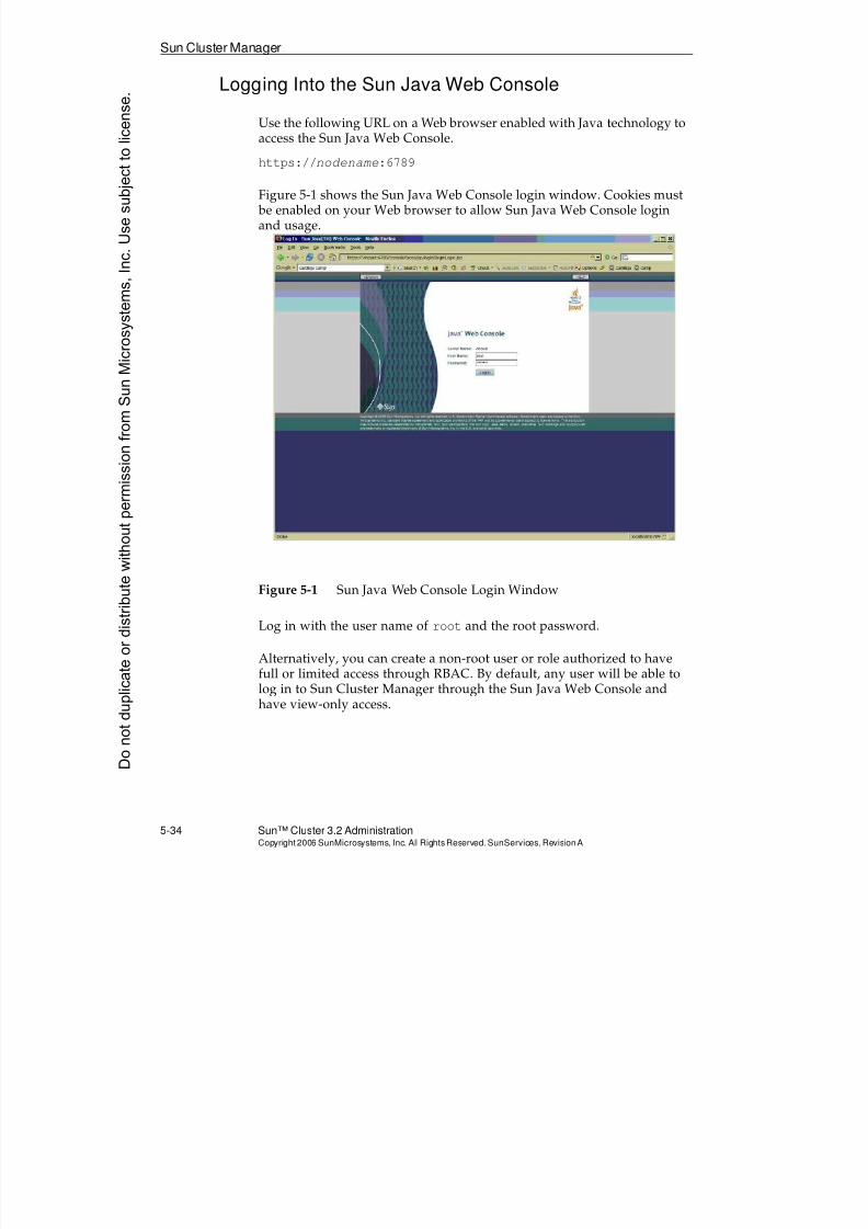
8/4/2019 Sun Cluster 3.2 Administration VC-ES-345
http://slidepdf.com/reader/full/sun-cluster-32-administration-vc-es-345 254/585
Sun Cluster Manager
5-34 Sun™ Cluster 3.2 AdministrationCopyright2006 SunMicrosystems, Inc. AllRights Reserved.SunServices,RevisionA
Logging Into the Sun Java Web Console
Use the following URL on a Web browser enabled with Java technology toaccess the Sun Java Web Console.
https://nodename:6789
Figure 5-1 shows the Sun Java Web Console login window. Cookies must be enabled on your Web browser to allow Sun Java Web Console loginand usage.
Figure 5-1 Sun Java Web Console Login Window
Log in with the user name of root and the root password.
Alternatively, you can create a non-root user or role authorized to havefull or limited access through RBAC. By default, any user will be able tolog in to Sun Cluster Manager through the Sun Java Web Console andhave view-only access.
Donotduplicate
ordistributewithoutpermissionfrom SunMicrosystems,Inc.Usesubject
tolicense.
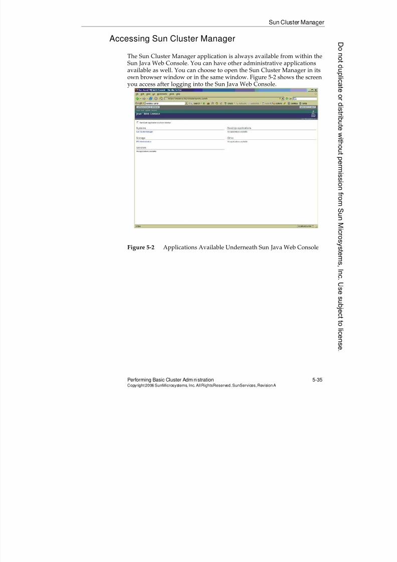
8/4/2019 Sun Cluster 3.2 Administration VC-ES-345
http://slidepdf.com/reader/full/sun-cluster-32-administration-vc-es-345 255/585
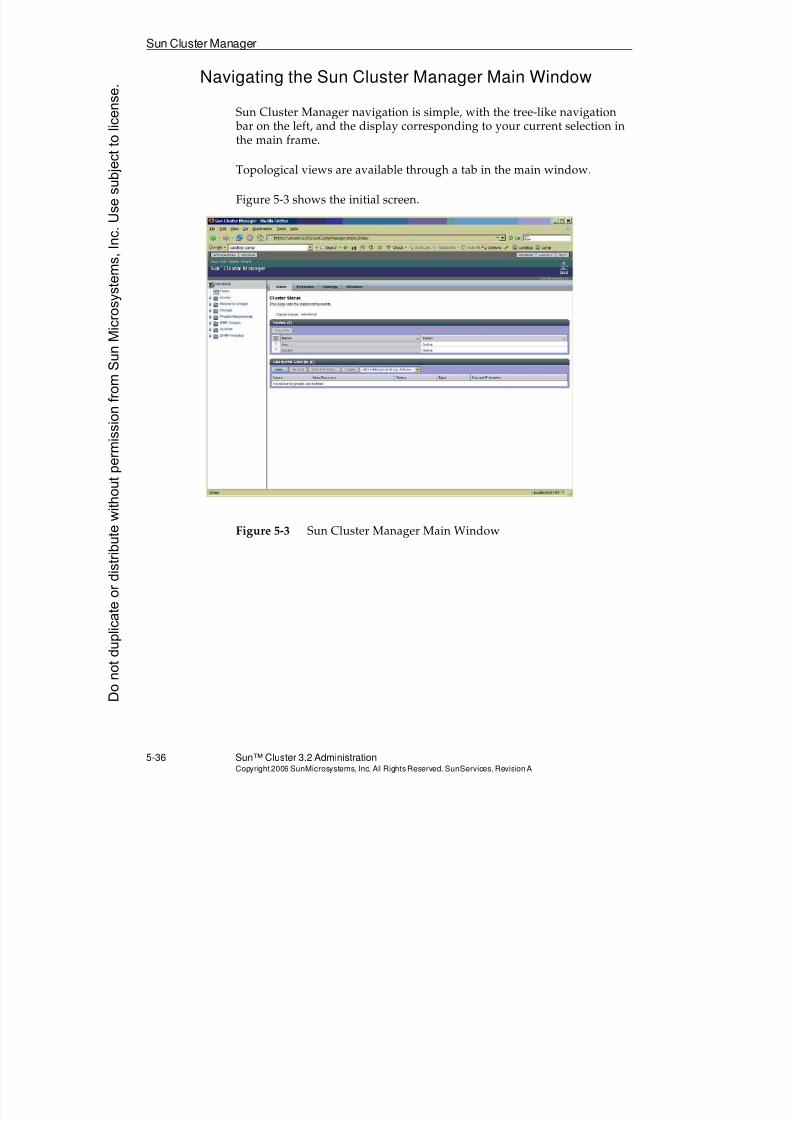
8/4/2019 Sun Cluster 3.2 Administration VC-ES-345
http://slidepdf.com/reader/full/sun-cluster-32-administration-vc-es-345 256/585
Sun Cluster Manager
5-36 Sun™ Cluster 3.2 AdministrationCopyright2006 SunMicrosystems, Inc. AllRights Reserved.SunServices,RevisionA
Navigating the Sun Cluster Manager Main Window
Sun Cluster Manager navigation is simple, with the tree-like navigation bar on the left, and the display corresponding to your current selection inthe main frame.
Topological views are available through a tab in the main window.
Figure 5-3 shows the initial screen.
Figure 5-3 Sun Cluster Manager Main Window
Donotduplicate
ordistributewithoutpermissionfrom SunMicrosystems,Inc.Usesubject
tolicense.
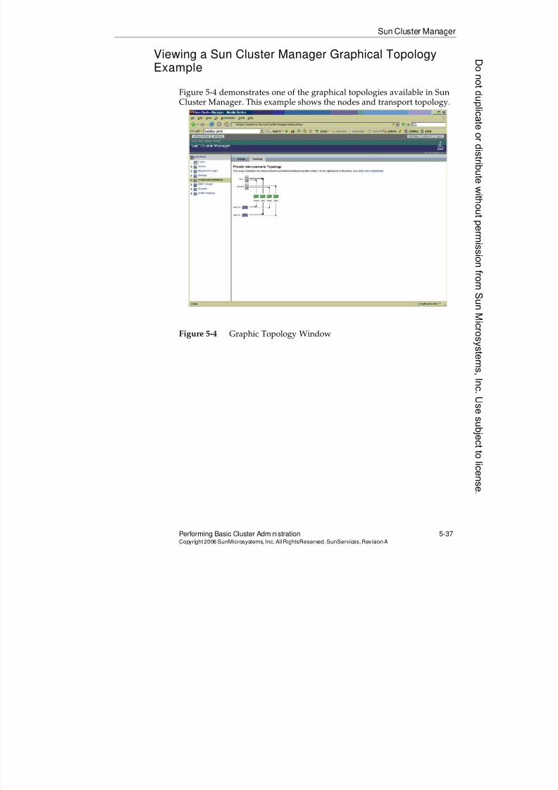
8/4/2019 Sun Cluster 3.2 Administration VC-ES-345
http://slidepdf.com/reader/full/sun-cluster-32-administration-vc-es-345 257/585
8/4/2019 Sun Cluster 3.2 Administration VC-ES-345
http://slidepdf.com/reader/full/sun-cluster-32-administration-vc-es-345 258/585
8/4/2019 Sun Cluster 3.2 Administration VC-ES-345
http://slidepdf.com/reader/full/sun-cluster-32-administration-vc-es-345 259/585
8/4/2019 Sun Cluster 3.2 Administration VC-ES-345
http://slidepdf.com/reader/full/sun-cluster-32-administration-vc-es-345 260/585
8/4/2019 Sun Cluster 3.2 Administration VC-ES-345
http://slidepdf.com/reader/full/sun-cluster-32-administration-vc-es-345 261/585
Controlling Clusters
Performing Basic Cluster Administration 5-41Copyright2006 SunMicrosystems, Inc. AllRightsReserved. SunServices,RevisionA
Booting Nodes Into Non-Cluster Mode
Occasionally, you might want to boot a node without it joining the cluster.This might be to debug some sort of problem preventing a node from joining a cluster, or to perform maintenance. For example, you upgrade
the cluster software itself when a node is booted into non-cluster mode.Other nodes might still be up running your clustered applications.
To other nodes that are still booted into the cluster, a node that is bootedinto non-cluster node looks like it has failed completely. It can not bereached across the cluster transport.
To boot a node to non-cluster mode you supply the -x boot option, whichgets passed through to the kernel.
Booting a SPARC Platform Machine With the -x
Command
For a SPARC-based machine, booting is simple:
{1} ok boot -x
Resetting ...
Rebooting with command: boot -x
Boot device: /pci@1f,4000/scsi@3/disk@0,0:a File and args: -xSunOS Release 5.10 Version Generic_118833-17 64-bit
Copyright 1983-2005 Sun Microsystems, Inc. All rights reserved.
Use is subject to license terms.
Hostname: vincent
vincent console login: root
Password:
Jul 10 00:31:50 vincent login: ROOT LOGIN /dev/console
Last login: Mon Jul 10 00:19:32 on console
Sun Microsystems Inc. SunOS 5.10 Generic January 2005
# cluster status
cluster: (C374108) Node is not in cluster mode.
8/4/2019 Sun Cluster 3.2 Administration VC-ES-345
http://slidepdf.com/reader/full/sun-cluster-32-administration-vc-es-345 262/585
Controlling Clusters
5-42 Sun™ Cluster 3.2 AdministrationCopyright2006 SunMicrosystems, Inc. AllRights Reserved.SunServices,RevisionA
Booting an x86 Platform Machine With the -x
Command
For an x86 machine, booting is a little more complicated.
For versions of Solaris 10 OS supported with Sun Cluster 3.2 (Update 3and above), the Gnu boot menus (GRUB) are automatically used. As themachine boots, you see the following menu, with the normal OShighlighted:
GNU GRUB version 0.95 (615K lower / 2095552K upper memory)
+----------------------------------------------------------------------+
| Solaris 10 11/06 s10x_u3wos_08 X86 |
| Solaris failsafe |
+---------------------------------------------------------------------+
Use the ^ and v keys to select which entry is highlighted.
Press enter to boot the selected OS, 'e' to edit the
commands before booting, or 'c' for a command-line.
The highlighted entry will be booted automatically in 20 seconds.
With the normal Solaris 10 OS highlighted, press the e key to edit the bootparameters. You see the following screen:
GNU GRUB version 0.95 (615K lower / 2095552K upper memory)
+----------------------------------------------------------------------+| root (hd0,0,a) |
| kernel /platform/i86pc/multiboot |
| module /platform/i86pc/boot_archive |
+----------------------------------------------------------------------+
Use the ^ and v keys to select which entry is highlighted.
Press 'b' to boot, 'e' to edit the selected command in the
boot sequence, 'c' for a command-line, 'o' to open a new line
after ('O' for before) the selected line, 'd' to remove the
selected line, or escape to go back to the main menu.
Donotduplicate
ordistributewithoutpermissionfrom SunMicrosystems,Inc.Usesubject
tolicense.
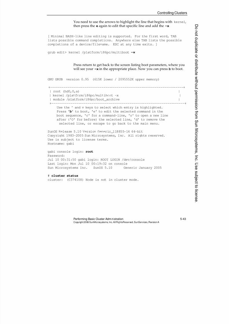
8/4/2019 Sun Cluster 3.2 Administration VC-ES-345
http://slidepdf.com/reader/full/sun-cluster-32-administration-vc-es-345 263/585
Controlling Clusters
Performing Basic Cluster Administration 5-43Copyright2006 SunMicrosystems, Inc. AllRightsReserved. SunServices,RevisionA
You need to use the arrows to highlight the line that begins with kernel,then press the e again to edit that specific line and add the -x
[ Minimal BASH-like line editing is supported. For the first word, TAB
lists possible command completions. Anywhere else TAB lists the possible
completions of a device/filename. ESC at any time exits. ]
grub edit> kernel /platform/i86pc/multiboot -x
Press return to get back to the screen listing boot parameters, where youwill see your -x in the appropriate place. Now you can press b to boot.
GNU GRUB version 0.95 (615K lower / 2095552K upper memory)
+----------------------------------------------------------------------+| root (hd0,0,a) |
| kernel /platform/i86pc/multiboot -x |
| module /platform/i86pc/boot_archive |
+----------------------------------------------------------------------+
Use the ^ and v keys to select which entry is highlighted.
Press ' b' to boot, 'e' to edit the selected command in the
boot sequence, 'c' for a command-line, 'o' to open a new line
after ('O' for before) the selected line, 'd' to remove the
selected line, or escape to go back to the main menu.
SunOS Release 5.10 Version Generic_118855-14 64-bitCopyright 1983-2005 Sun Microsystems, Inc. All rights reserved.
Use is subject to license terms.
Hostname: gabi
gabi console login: root
Password:
Jul 10 00:31:50 gabi login: ROOT LOGIN /dev/console
Last login: Mon Jul 10 00:19:32 on console
Sun Microsystems Inc. SunOS 5.10 Generic January 2005
# cluster statuscluster: (C374108) Node is not in cluster mode.
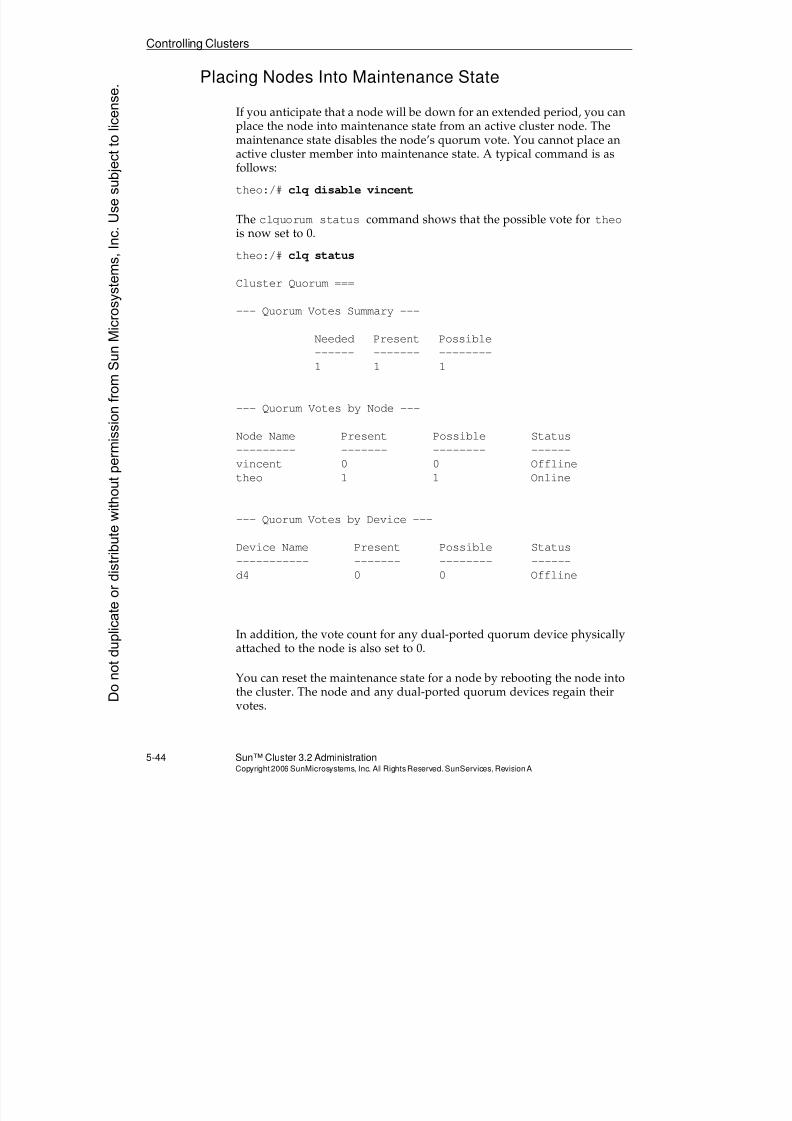
8/4/2019 Sun Cluster 3.2 Administration VC-ES-345
http://slidepdf.com/reader/full/sun-cluster-32-administration-vc-es-345 264/585
Controlling Clusters
5-44 Sun™ Cluster 3.2 AdministrationCopyright2006 SunMicrosystems, Inc. AllRights Reserved.SunServices,RevisionA
Placing Nodes Into Maintenance State
If you anticipate that a node will be down for an extended period, you canplace the node into maintenance state from an active cluster node. Themaintenance state disables the node’s quorum vote. You cannot place an
active cluster member into maintenance state. A typical command is asfollows:
theo:/# clq disable vincent
The clquorum status command shows that the possible vote for theois now set to 0.
theo:/# clq status
Cluster Quorum ===
--- Quorum Votes Summary ---
Needed Present Possible
------ ------- --------
1 1 1
--- Quorum Votes by Node ---
Node Name Present Possible Status
--------- ------- -------- ------vincent 0 0 Offline
theo 1 1 Online
--- Quorum Votes by Device ---
Device Name Present Possible Status
----------- ------- -------- ------
d4 0 0 Offline
In addition, the vote count for any dual-ported quorum device physicallyattached to the node is also set to 0.
You can reset the maintenance state for a node by rebooting the node intothe cluster. The node and any dual-ported quorum devices regain theirvotes.
Donotduplicate
ordistributewithoutpermissionfrom SunMicrosystems,Inc.Usesubject
tolicense.
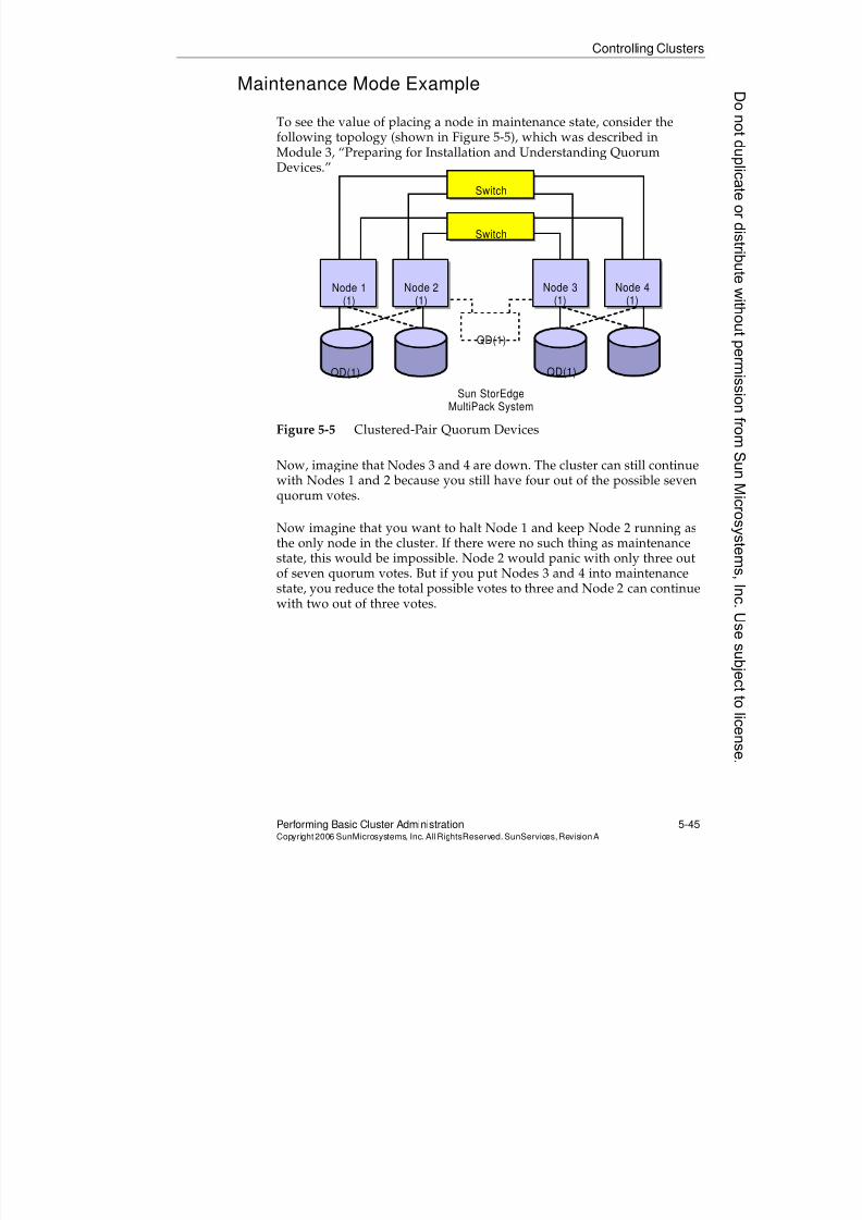
8/4/2019 Sun Cluster 3.2 Administration VC-ES-345
http://slidepdf.com/reader/full/sun-cluster-32-administration-vc-es-345 265/585
Controlling Clusters
Performing Basic Cluster Administration 5-45Copyright2006 SunMicrosystems, Inc. AllRightsReserved. SunServices,RevisionA
Maintenance Mode Example
To see the value of placing a node in maintenance state, consider thefollowing topology (shown in Figure 5-5), which was described inModule 3, “Preparing for Installation and Understanding Quorum
Devices.”
Figure 5-5 Clustered-Pair Quorum Devices
Now, imagine that Nodes 3 and 4 are down. The cluster can still continuewith Nodes 1 and 2 because you still have four out of the possible seven
quorum votes.
Now imagine that you want to halt Node 1 and keep Node 2 running asthe only node in the cluster. If there were no such thing as maintenancestate, this would be impossible. Node 2 would panic with only three outof seven quorum votes. But if you put Nodes 3 and 4 into maintenancestate, you reduce the total possible votes to three and Node 2 can continuewith two out of three votes.
Switch
Switch
Node 1(1)
Node 2(1)
Node 3(1)
Node 4(1)
QD(1) QD(1)
QD(1)
Sun StorEdgeMultiPack System
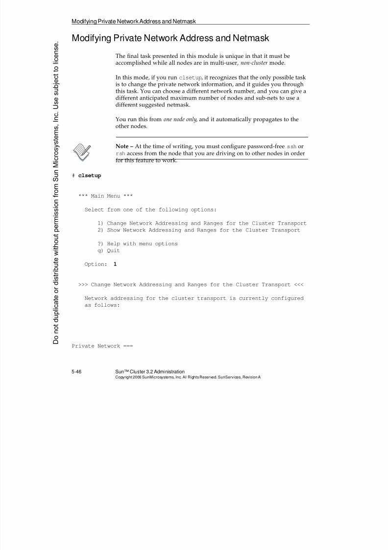
8/4/2019 Sun Cluster 3.2 Administration VC-ES-345
http://slidepdf.com/reader/full/sun-cluster-32-administration-vc-es-345 266/585
Modifying Private NetworkAddress and Netmask
5-46 Sun™ Cluster 3.2 AdministrationCopyright2006 SunMicrosystems, Inc. AllRights Reserved.SunServices,RevisionA
Modifying Private Network Address and Netmask
The final task presented in this module is unique in that it must beaccomplished while all nodes are in multi-user, non-cluster mode.
In this mode, if you run clsetup, it recognizes that the only possible taskis to change the private network information, and it guides you throughthis task. You can choose a different network number, and you can give adifferent anticipated maximum number of nodes and sub-nets to use adifferent suggested netmask.
You run this from one node only, and it automatically propagates to theother nodes.
Note – At the time of writing, you must configure password-free ssh orrsh access from the node that you are driving on to other nodes in orderfor this feature to work.
# clsetup
*** Main Menu ***
Select from one of the following options:
1) Change Network Addressing and Ranges for the Cluster Transport2) Show Network Addressing and Ranges for the Cluster Transport
?) Help with menu options
q) Quit
Option: 1
>>> Change Network Addressing and Ranges for the Cluster Transport <<<
Network addressing for the cluster transport is currently configuredas follows:
Private Network ===Donotduplicate
ordistributewithoutpermissionfrom SunMicrosystems,Inc.Usesubject
tolicense.
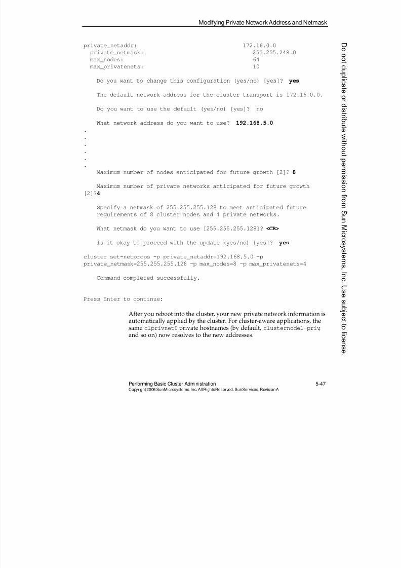
8/4/2019 Sun Cluster 3.2 Administration VC-ES-345
http://slidepdf.com/reader/full/sun-cluster-32-administration-vc-es-345 267/585
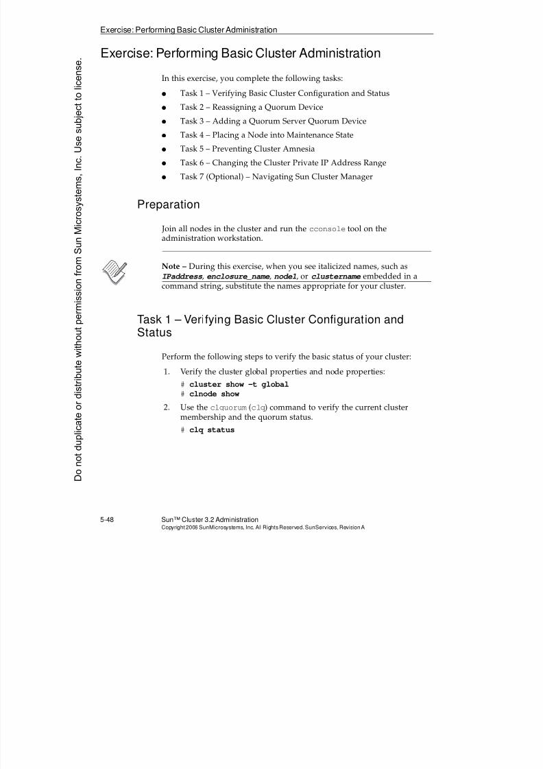
8/4/2019 Sun Cluster 3.2 Administration VC-ES-345
http://slidepdf.com/reader/full/sun-cluster-32-administration-vc-es-345 268/585
Exercise: Performing Basic Cluster Administration
5-48 Sun™ Cluster 3.2 AdministrationCopyright2006 SunMicrosystems, Inc. AllRights Reserved.SunServices,RevisionA
Exercise: Performing Basic Cluster Administration
In this exercise, you complete the following tasks:
q Task 1 – Verifying Basic Cluster Configuration and Status
q Task 2 – Reassigning a Quorum Device
q Task 3 – Adding a Quorum Server Quorum Device
q Task 4 – Placing a Node into Maintenance State
q Task 5 – Preventing Cluster Amnesia
q Task 6 – Changing the Cluster Private IP Address Range
q Task 7 (Optional) – Navigating Sun Cluster Manager
Preparation
Join all nodes in the cluster and run the cconsole tool on theadministration workstation.
Note – During this exercise, when you see italicized names, such asIPaddress, enclosure_name, node1, or clustername embedded in acommand string, substitute the names appropriate for your cluster.
Task 1 – Verifying Basic Cluster Configuration andStatus
Perform the following steps to verify the basic status of your cluster:
1. Verify the cluster global properties and node properties:
# cluster show -t global
# clnode show
2. Use the clquorum (clq) command to verify the current cluster
membership and the quorum status.# clq status
Donotduplicate
ordistributewithoutpermissionfrom SunMicrosystems,Inc.Usesubject
tolicense.
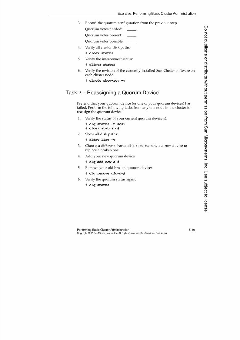
8/4/2019 Sun Cluster 3.2 Administration VC-ES-345
http://slidepdf.com/reader/full/sun-cluster-32-administration-vc-es-345 269/585
Exercise: Performing Basic Cluster Administration
Performing Basic Cluster Administration 5-49Copyright2006 SunMicrosystems, Inc. AllRightsReserved. SunServices,RevisionA
3. Record the quorum configuration from the previous step.
Quorum votes needed: _____
Quorum votes present: _____
Quorum votes possible: _____
4. Verify all cluster disk paths.
# cldev status
5. Verify the interconnect status:
# clintr status
6. Verify the revision of the currently installed Sun Cluster software oneach cluster node.
# clnode show-rev -v
Task 2 – Reassigning a Quorum Device
Pretend that your quorum device (or one of your quorum devices) hasfailed. Perform the following tasks from any one node in the cluster toreassign the quorum device:
1. Verify the status of your current quorum device(s):
# clq status -t scsi
# cldev status d#
2. Show all disk paths:
# cldev list -v
3. Choose a different shared disk to be the new quorum device toreplace a broken one.
4. Add your new quorum device:
# clq add new-d-#
5. Remove your old broken quorum device:
# clq remove old-d-#
6. Verify the quorum status again:
# clq status
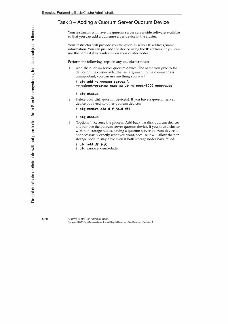
8/4/2019 Sun Cluster 3.2 Administration VC-ES-345
http://slidepdf.com/reader/full/sun-cluster-32-administration-vc-es-345 270/585

8/4/2019 Sun Cluster 3.2 Administration VC-ES-345
http://slidepdf.com/reader/full/sun-cluster-32-administration-vc-es-345 271/585
Exercise: Performing Basic Cluster Administration
Performing Basic Cluster Administration 5-51Copyright2006 SunMicrosystems, Inc. AllRightsReserved. SunServices,RevisionA
Task 4 – Placing a Node into Maintenance State
Perform the following steps to place a node into maintenance state:
1. Shut down node 2 using halt or init 0
2. On Node 1, use the clquorum command to place Node 2 intomaintenance state.
# clq disable name_of_node2
3. Verify the cluster quorum status.
# clq status
Note – The number of possible quorum votes should be reduced
4. Boot Node 2 again. This should reset its maintenance state. Youshould see the following message on both nodes:
NOTICE: CMM: Votecount changed from 0 to 1 for node
nodename
5. Verify the cluster quorum configuration again. The number ofpossible quorum votes should be back to normal.
Task 5 – Preventing Cluster Amnesia
Perform the following steps to demonstrate how the cluster preventscluster amnesia, using persistent reservations on the quorum device. Youcan review the information about what you will see by checkingModule 3, “Preparing for Installation and Understanding QuorumDevices.”
1. Verify that all nodes are active cluster members. If you have athree-node cluster (Pair +1), shut down the node not attached tostorage with init 0.
2. Shut down Node 1 with init 0.
3. Shut down Node 2.
# init 0
4. Boot Node 1.
Node 1 should hang waiting for operational quorum. This is becausethe reservation key for Node 1 has been removed from the quorumdisk(s).
8/4/2019 Sun Cluster 3.2 Administration VC-ES-345
http://slidepdf.com/reader/full/sun-cluster-32-administration-vc-es-345 272/585
Exercise: Performing Basic Cluster Administration
5-52 Sun™ Cluster 3.2 AdministrationCopyright2006 SunMicrosystems, Inc. AllRights Reserved.SunServices,RevisionA
5. Now boot Node 2. Both nodes should complete the cluster softwarestartup sequence and join in clustered operation.
Task 6 – Changing the Cluster Private IP Address
Range
Perform the following steps while all nodes are booted to non-clustermode:
1. Shut down the entire cluster by typing on any one node:
# cluster shutdown -y -g0
2. Boot all nodes to non-cluster mode using boot -x
3. Choose (any) single node on which to perform the commands.
4. On all other nodes enable root rsh access from the chosen node:# echo name_of_chosen_node >>/.rhosts
5. On the chosen node only, run the procedure to change the clusterprivate IP address range:
a. Execute the clsetup command.
b. Choose option 1 to change the configuration.
c. Verify (answer yes) when asked if you want to change thesettings.
d. Answer nowhen asked if you want to accept the default baseaddress.
e. Enter a new available private address base address. Consultyour instructor if you are not sure. Do not accidentally conflictwith the public network address space.
f. Answer nowhen asked if you want to accept the defaultnetmask.
g. Enter 8 for the maximum number of nodes.
h. Enter 4 for the maximum number of private networks.
i. Accept the suggested netmask (255.255.255.128). j. Confirm that you want to proceed with the update.
Donotduplicate
ordistributewithoutpermissionfrom SunMicrosystems,Inc.Usesubject
tolicense.
8/4/2019 Sun Cluster 3.2 Administration VC-ES-345
http://slidepdf.com/reader/full/sun-cluster-32-administration-vc-es-345 273/585
Exercise: Performing Basic Cluster Administration
Performing Basic Cluster Administration 5-53Copyright2006 SunMicrosystems, Inc. AllRightsReserved. SunServices,RevisionA
6. When the command succeeds, reboot all nodes back into the cluster.
7. Verify that the private network addresses have changed.
a. Use ifconfig -a and verify the information for the physicalprivate network adapters and for the clprivnet0 adapter.
b. Verify the output ofcluster show -t global.
Task 7 (Optional) – Navigating Sun Cluster Manager
Perform the following steps:
1. In a Web browser window on your administrative workstation, typethe following URL:
https://nodename:6789
where nodename is the name of any of your nodes currently bootedinto the cluster.
If you do not succeed in reaching the Sun Java Web Console, youmight need to disable or set exceptions for the proxy settings in yourWeb browser. Ask your instructor if you need help.
If you are running the class with remote equipment, you might beable to use a Web browser to access Sun Cluster Manager in one oftwo ways:
a. Run the browser on your remote display.
b. Run the browser locally and tunnel the traffic through ssh.
Note – Consult your instructor about how this will be accomplished.
2. Log in as the user root with the root password.
3. Navigate to the Sun Cluster Manager application.
4. Familiarize yourself with Sun Cluster Manager navigation and thetopological views.

8/4/2019 Sun Cluster 3.2 Administration VC-ES-345
http://slidepdf.com/reader/full/sun-cluster-32-administration-vc-es-345 274/585
Exercise Summary
5-54 Sun™ Cluster 3.2 AdministrationCopyright2006 SunMicrosystems, Inc. AllRights Reserved.SunServices,RevisionA
Exercise Summary
?
!
Discussion – Take a few minutes to discuss what experiences, issues, ordiscoveries you had during the lab exercises.
q Experiences
q Interpretations
q Conclusions
q Applications
Donotduplicate
ordistributewithoutpermissionfrom SunMicrosystems,Inc.Usesubject
tolicense.
8/4/2019 Sun Cluster 3.2 Administration VC-ES-345
http://slidepdf.com/reader/full/sun-cluster-32-administration-vc-es-345 275/585
6-1Copyright2006 SunMicrosystems, Inc. AllRights Reserved.SunServices,RevisionA
Module 6
UsingVERITAS Volume ManagerWithSunClusterSoftware
Objectives
Upon completion of this module, you should be able to:
q Describe the most important concepts of VERITAS Volume Manager(VxVM) and issues involved in using VxVM in the Sun Cluster 3.2software environment
q Differentiate between bootdg/rootdg and shared storage diskgroups
q Initialize a VERITAS Volume Manager disk
q Describe the basic objects in a disk group
q Describe the types of volumes that will be created for Sun Cluster 3.2
software environmentsq Describe the general procedures and restrictions for installing and
administering VxVM in the cluster
q Use basic commands to put disks in disk groups and build volumes
q Describe the two flags used to mark disks under the typical hotrelocation
q Register, manage, and resynchronize VxVM disk groups as clusterdevice groups
q Create global and failover file systems on VxVM volumes
q Describe the procedure used for mirroring the boot drive
q Describe ZFS and its built-in volume management in contrast totraditional file systems used with a volume manager like VxVM
8/4/2019 Sun Cluster 3.2 Administration VC-ES-345
http://slidepdf.com/reader/full/sun-cluster-32-administration-vc-es-345 276/585
Relevance
6-2 Sun™Cluster 3 .2AdministrationCopyright2006 SunMicrosystems, Inc. AllRights Reserved.SunServices,RevisionA
Relevance
?
!
Discussion – The following questions are relevant to understanding thecontent of this module:
q Why is it so important to mirror JBOD disks with VxVM if thecluster already provides node-to-node failover?
q Are there any VxVM feature restrictions when VxVM is used in theSun Cluster software environment?
q In what way does Sun Cluster provide high availability for diskgroups?
q Can your prevent Sun Cluster from providing a global device servicefor your volumes?
Donotduplicate
ordistributewithoutpermissionfrom SunMicrosystems,Inc.Usesubject
tolicense.
8/4/2019 Sun Cluster 3.2 Administration VC-ES-345
http://slidepdf.com/reader/full/sun-cluster-32-administration-vc-es-345 277/585
Additional Resources
UsingVERITAS Volume Manager W ith SunC luster Software 6-3Copyright2006 SunMicrosystems, Inc. AllRightsReserved. SunServices,RevisionA
Additional Resources
Additional resources – The following references provide additional
information on the topics described in this module:q Sun Cluster System Administration Guide for Solaris OS, part number
819-2971.
q Sun Cluster Software Installation Guide for Solaris OS, part number 819-2970.
q Sun Cluster Concepts Guide for Solaris OS, part number 819-2969.
q Veritas Storage Foundation Installation Guide (version 5.0 for Solaris),Symantec Corporation (available with Veritas Storage Foundationsoftware).
8/4/2019 Sun Cluster 3.2 Administration VC-ES-345
http://slidepdf.com/reader/full/sun-cluster-32-administration-vc-es-345 278/585
Introducing VxVM in the Sun Cluster SoftwareEnvironment
6-4 Sun™Cluster 3 .2AdministrationCopyright2006 SunMicrosystems, Inc. AllRights Reserved.SunServices,RevisionA
Introducing VxVM in the Sun Cluster SoftwareEnvironment
This module does not intend to replace a full class in VxVM
administration. Rather, it briefly introduces the most important conceptsof VxVM and focuses on issues involved in using VxVM in theSun Cluster 3.2 environment.
Only the following versions of VxVM are supported in Sun Cluster 3.2software:
q VxVM 4.1 MP1 Solaris 9 OS/Solaris 10 OS (SPARC)
q VxVM 5.0 Solaris 9 OS/Solaris 10 OS (SPARC)
q VxVM 4.1 MP2 for Solaris 10 OS (x86 – AMD 64 platform)
Donotduplicate
ordistributewithoutpermissionfrom SunMicrosystems,Inc.Usesubject
tolicense.
8/4/2019 Sun Cluster 3.2 Administration VC-ES-345
http://slidepdf.com/reader/full/sun-cluster-32-administration-vc-es-345 279/585
ExploringVxVM Disk Groups
UsingVERITAS Volume Manager W ith SunC luster Software 6-5Copyright2006 SunMicrosystems, Inc. AllRightsReserved. SunServices,RevisionA
Exploring VxVM Disk Groups
The assignment of disk drives or logical units (LUNs) into disk groups isthe most important organizational concept for managing VxVM in thecluster environment.
Every disk or LUN used by VxVM must be a member of exactly one diskgroup. Disks in the same disk group act as an organizational unit.
Shared Storage Disk Groups
All of the data associated with applications that run in the Sun Cluster 3.2software environment must be in storage that is physically ported to atleast two nodes. Disk groups are created using only disks in multiple
arrays that are connected to the same collection of nodes.
VERITAS Management on Local Disks (Optional inVxVM 4.x and Above)
Prior to VxVM 4.0, VxVM required that each node have an independentdisk group named rootdg. In these earlier versions you could notconfigure anything else in VxVM until rootdg was configured. Youneeded to have this disk group even if you did not intend VxVM to
manage your boot disk. In that case, you needed at least one (preferablytwo, for HA) sacrificial local disks so that you could have a rootdg.
Starting in VxVM 4.x, it is optional to have any disk group at all configuredfor the local disks. You can choose not to configure any VxVMconfigurations on local disks, and you are still able to create your sharedstorage disk groups.
If you want to have VxVM 4.x or 5.x manage your boot disk (that is, toencapsulate your boot disk), then you have this disk (and presumablyanother because there is no reason to encapsulate root if you are not going
to mirror it) in a dedicated local VxVM disk group. This group can haveany group name. VxVM automatically sets up a symbolic link so thatwhatever the actual group name is there will be a link to it called bootdg.
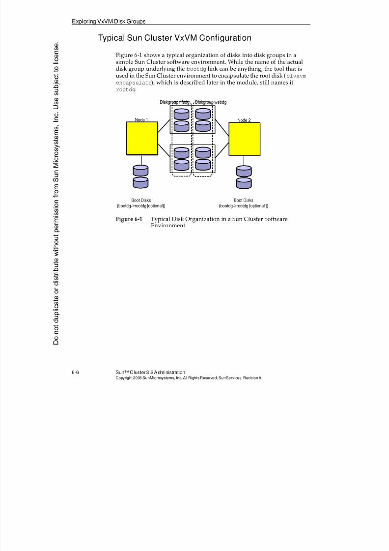
8/4/2019 Sun Cluster 3.2 Administration VC-ES-345
http://slidepdf.com/reader/full/sun-cluster-32-administration-vc-es-345 280/585
Exploring VxVM Disk Groups
6-6 Sun™Cluster 3 .2AdministrationCopyright2006 SunMicrosystems, Inc. AllRights Reserved.SunServices,RevisionA
Typical Sun Cluster VxVM Configuration
Figure 6-1 shows a typical organization of disks into disk groups in asimple Sun Cluster software environment. While the name of the actualdisk group underlying the bootdg link can be anything, the tool that is
used in the Sun Cluster environment to encapsulate the root disk (clvxvmencapsulate), which is described later in the module, still names itrootdg.
Figure 6-1 Typical Disk Organization in a Sun Cluster SoftwareEnvironment
Boot Disks
(bootdg->rootdg [optional])
Node 1
Boot Disks
(bootdg->rootdg [optional ])
Node 2
Diskgroup webdgDiskgroup nfsdg
Donotduplicate
ordistributewithoutpermissionfrom SunMicrosystems,Inc.Usesubject
tolicense.
8/4/2019 Sun Cluster 3.2 Administration VC-ES-345
http://slidepdf.com/reader/full/sun-cluster-32-administration-vc-es-345 281/585
ExploringVxVM Disk Groups
UsingVERITAS Volume Manager W ith SunC luster Software 6-7Copyright2006 SunMicrosystems, Inc. AllRightsReserved. SunServices,RevisionA
Shared Storage Disk Group Ownership
While the disks in disk groups used for Sun Cluster software applicationdata must be physically connected to at least two nodes, disk groups areowned, or imported, by only one node at a time. The node that is currently
importing a disk group is the one that does the following:
q It physically reads and writes data to the drives within the diskgroup.
q It manages the disk group. VxVM commands pertaining to thatdiskgroup can be issued only from the node importing the diskgroup.
q It can voluntarily give up ownership of the disk group by deportingthe disk group.
Sun Cluster Management of Disk Groups
After a disk group is managed by the cluster, the cluster is responsible forissuing all VxVM commands to import and deport disk groups. The nodecurrently importing the disk group becomes the primary device groupserver.
Registering VxVM disk groups so that the Sun Cluster software hasknowledge of them is described in‘‘Registering VxVM Disk Groups’’ on
page 6-32.
Sun Cluster Global Devices Within a Disk Group
While the fact that only one node imports a disk group remains true in theSun Cluster software environment, Sun Cluster software’s global deviceinfrastructure makes it appear that devices in the disk group are accessiblefrom all nodes in the cluster, including nodes that are not even physicallyconnected to the disks in the disk group.
All nodes that are not the current primary for a particular disk groupactually access the device data through the cluster transport. This applieseven for other nodes that are physically connected to the disks.
8/4/2019 Sun Cluster 3.2 Administration VC-ES-345
http://slidepdf.com/reader/full/sun-cluster-32-administration-vc-es-345 282/585
Exploring VxVM Disk Groups
6-8 Sun™Cluster 3 .2AdministrationCopyright2006 SunMicrosystems, Inc. AllRights Reserved.SunServices,RevisionA
VxVM Cluster Feature Used Only for Oracle RAC
You might see references throughout the VERITAS documentation to aCluster Volume Manager (CVM) feature, and creating disk groups with aspecific shared flag.
This is a separately licensed feature of VxVM that allows simultaneousaccess to disk group volumes by multiple nodes, directly through thestorage medium.
In the Sun Cluster 3.2 software, this VxVM feature can be used only by theOracle Real Application Clusters (RAC) application. The feature is notsupported on x86, however, you can run RAC using Solaris VolumeManager or without a volume manager.
Do not confuse the usage of shared storage disk group throughout thismodule with the CVM feature of VxVM.
Donotduplicate
ordistributewithoutpermissionfrom SunMicrosystems,Inc.Usesubject
tolicense.
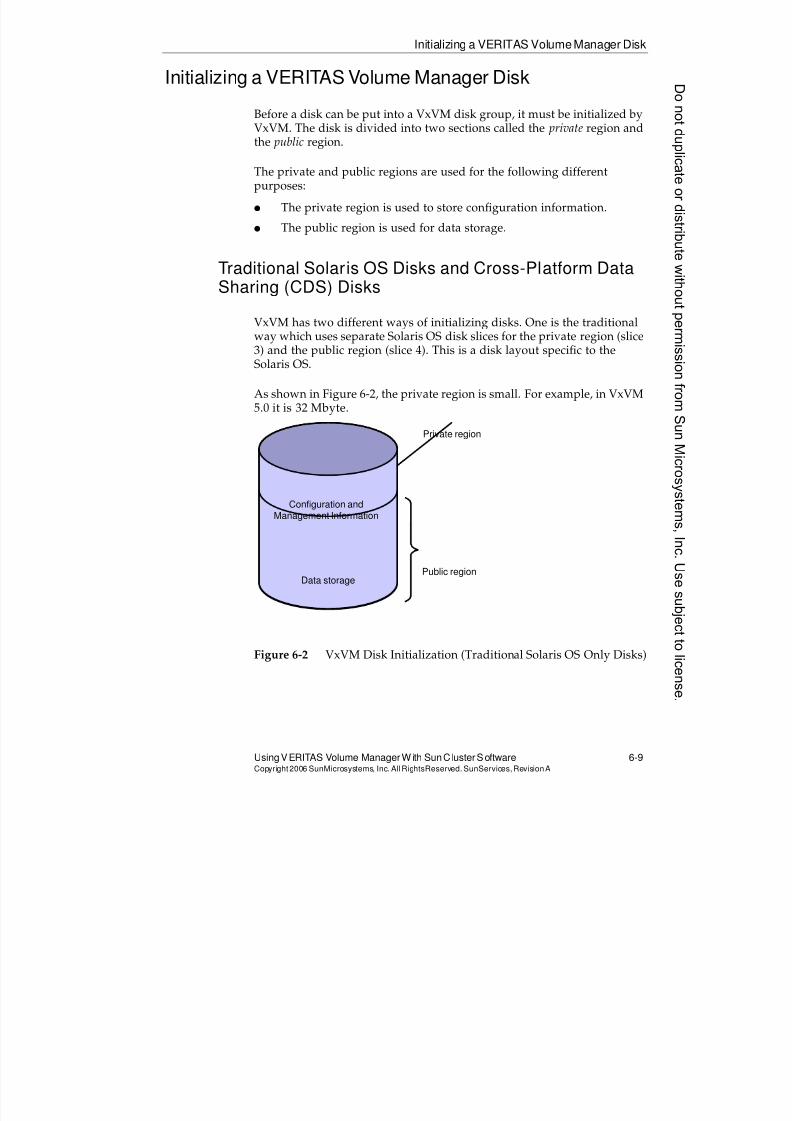
8/4/2019 Sun Cluster 3.2 Administration VC-ES-345
http://slidepdf.com/reader/full/sun-cluster-32-administration-vc-es-345 283/585
Initializing a VERITAS Volume Manager Disk
UsingVERITAS Volume Manager W ith SunC luster Software 6-9Copyright2006 SunMicrosystems, Inc. AllRightsReserved. SunServices,RevisionA
Initializing a VERITAS Volume Manager Disk
Before a disk can be put into a VxVM disk group, it must be initialized byVxVM. The disk is divided into two sections called the private region andthe public region.
The private and public regions are used for the following differentpurposes:
q The private region is used to store configuration information.
q The public region is used for data storage.
Traditional Solaris OS Disks and Cross-Platform DataSharing (CDS) Disks
VxVM has two different ways of initializing disks. One is the traditionalway which uses separate Solaris OS disk slices for the private region (slice3) and the public region (slice 4). This is a disk layout specific to theSolaris OS.
As shown in Figure 6-2, the private region is small. For example, in VxVM5.0 it is 32 Mbyte.
Figure 6-2 VxVM Disk Initialization (Traditional Solaris OS Only Disks)
Configuration andManagement Information
Public region
Private region
Data storage
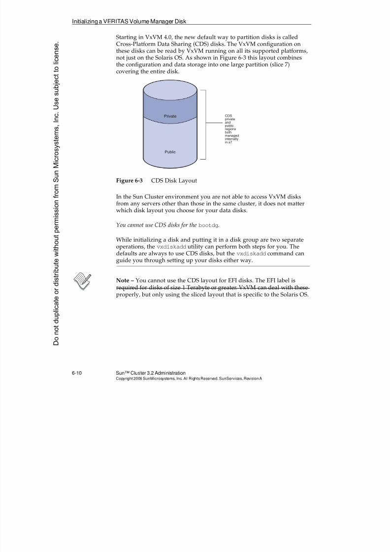
8/4/2019 Sun Cluster 3.2 Administration VC-ES-345
http://slidepdf.com/reader/full/sun-cluster-32-administration-vc-es-345 284/585
Initializing a VERITAS Volume Manager Disk
6-10 Sun™ Cluster 3.2 AdministrationCopyright2006 SunMicrosystems, Inc. AllRights Reserved.SunServices,RevisionA
Starting in VxVM 4.0, the new default way to partition disks is calledCross-Platform Data Sharing (CDS) disks. The VxVM configuration onthese disks can be read by VxVM running on all its supported platforms,not just on the Solaris OS. As shown in Figure 6-3 this layout combinesthe configuration and data storage into one large partition (slice 7)
covering the entire disk.
Figure 6-3 CDS Disk Layout
In the Sun Cluster environment you are not able to access VxVM disksfrom any servers other than those in the same cluster, it does not matterwhich disk layout you choose for your data disks.
You cannot use CDS disks for the bootdg.
While initializing a disk and putting it in a disk group are two separateoperations, the vxdiskadd utility can perform both steps for you. Thedefaults are always to use CDS disks, but the vxdiskadd command canguide you through setting up your disks either way.
Note – You cannot use the CDS layout for EFI disks. The EFI label isrequired for disks of size 1 Terabyte or greater. VxVM can deal with theseproperly, but only using the sliced layout that is specific to the Solaris OS.
Private
Public
CDSprivateandpublicregionsbothmanagedinternallyin s7
Donotduplicate
ordistributewithoutpermissionfrom SunMicrosystems,Inc.Usesubject
tolicense.
8/4/2019 Sun Cluster 3.2 Administration VC-ES-345
http://slidepdf.com/reader/full/sun-cluster-32-administration-vc-es-345 285/585
Reviewing the Basic Objects in a Disk Group
Using VERITAS Volume Manager With Sun Cluster Software 6-11Copyright2006 SunMicrosystems, Inc. AllRightsReserved. SunServices,RevisionA
Reviewing the Basic Objects in a Disk Group
This section reviews some of the basic naming terminology of objects indisk groups. Many of the objects (such as subdisks and plexes) are oftenautomatically created for you when you use the recommended commands(such as vxassist) to create volumes.
Although the GUI for VxVM furnishes useful visual status information,the most reliable and the quickest method of checking status is from thecommand line. Command-line status tools are easy to use in script files,cron jobs, and remote logins.
Disk Names or Media Names
Each disk that you put in a diskgroup has a logical name that you canassign. This logical name can be anything, and is independent of itsSolaris OS logical device name (c#t#d#).
VxVM does not use the Sun Cluster Disk IDs (DIDs). Its own logicalnaming scheme serves a similar purpose.
Subdisk
A subdisk is a contiguous piece of a physical disk that is used as a building block for a volume. The smallest possible subdisk is 1 block andthe largest is the whole public region of the disk.
Plex
A plex is a collection of subdisk objects, and describes the layout of thesubdisks as either concatenated, striped, or RAID5. A plex, or data plex,has the following characteristics:
q
A plex is a copy of the data in the volume.q A volume with one data plex is not mirrored.
q A volume with two data plexes is mirrored.
q A volume with five data plexes is mirrored five ways.
8/4/2019 Sun Cluster 3.2 Administration VC-ES-345
http://slidepdf.com/reader/full/sun-cluster-32-administration-vc-es-345 286/585
Reviewing the Basic Objects in a Disk Group
6-12 Sun™ Cluster 3.2 AdministrationCopyright2006 SunMicrosystems, Inc. AllRights Reserved.SunServices,RevisionA
Volume
The volume is the actual logical storage device created and used by alldisk consumers. The disk consumers may be file systems, swap space, orapplications, such as Oracle using raw volumes.
Only volumes are given block and character device files.
The basic volume creation method (vxassist) lets you specify parametersfor your volume. This method automatically creates the subdisks andplexes for you.
Layered Volume
A layered volume is a technique used by VxVM that lets you create RAID1+0 configurations. For example, you can create two mirrored volumes,and then use those as components in a larger striped volume. This stripedvolume contains a single plex composed of sub-volumes rather thansubdisks.
While this sounds complicated, the automation involved in therecommended vxassist command makes such configurations easy tocreate.
Donotduplicate
ordistributewithoutpermissionfrom SunMicrosystems,Inc.Usesubject
tolicense.
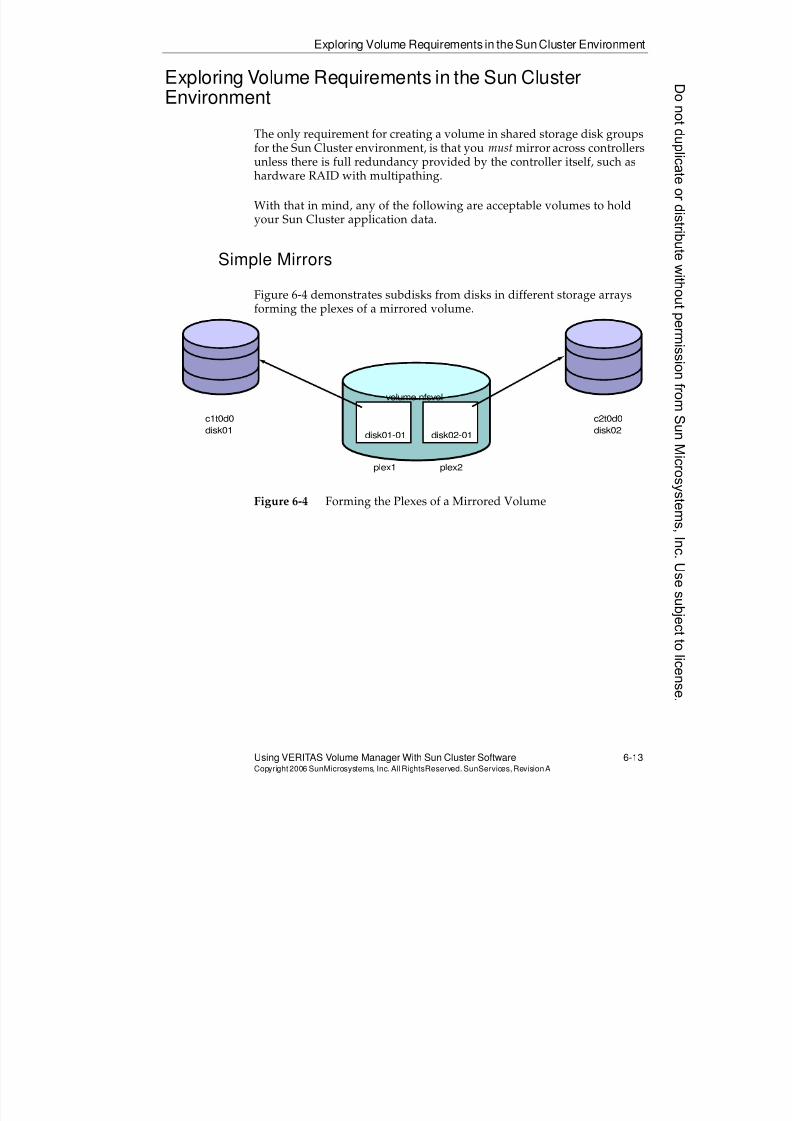
8/4/2019 Sun Cluster 3.2 Administration VC-ES-345
http://slidepdf.com/reader/full/sun-cluster-32-administration-vc-es-345 287/585
Exploring Volume Requirements in theSunCluster Environment
Using VERITAS Volume Manager With Sun Cluster Software 6-13Copyright2006 SunMicrosystems, Inc. AllRightsReserved. SunServices,RevisionA
Exploring Volume Requirements in the Sun ClusterEnvironment
The only requirement for creating a volume in shared storage disk groups
for the Sun Cluster environment, is that you must mirror across controllersunless there is full redundancy provided by the controller itself, such ashardware RAID with multipathing.
With that in mind, any of the following are acceptable volumes to holdyour Sun Cluster application data.
Simple Mirrors
Figure 6-4 demonstrates subdisks from disks in different storage arraysforming the plexes of a mirrored volume.
Figure 6-4 Forming the Plexes of a Mirrored Volume
c1t0d0
disk01
c2t0d0
disk02disk01-01 disk02-01
plex1 plex2
volume nfsvol
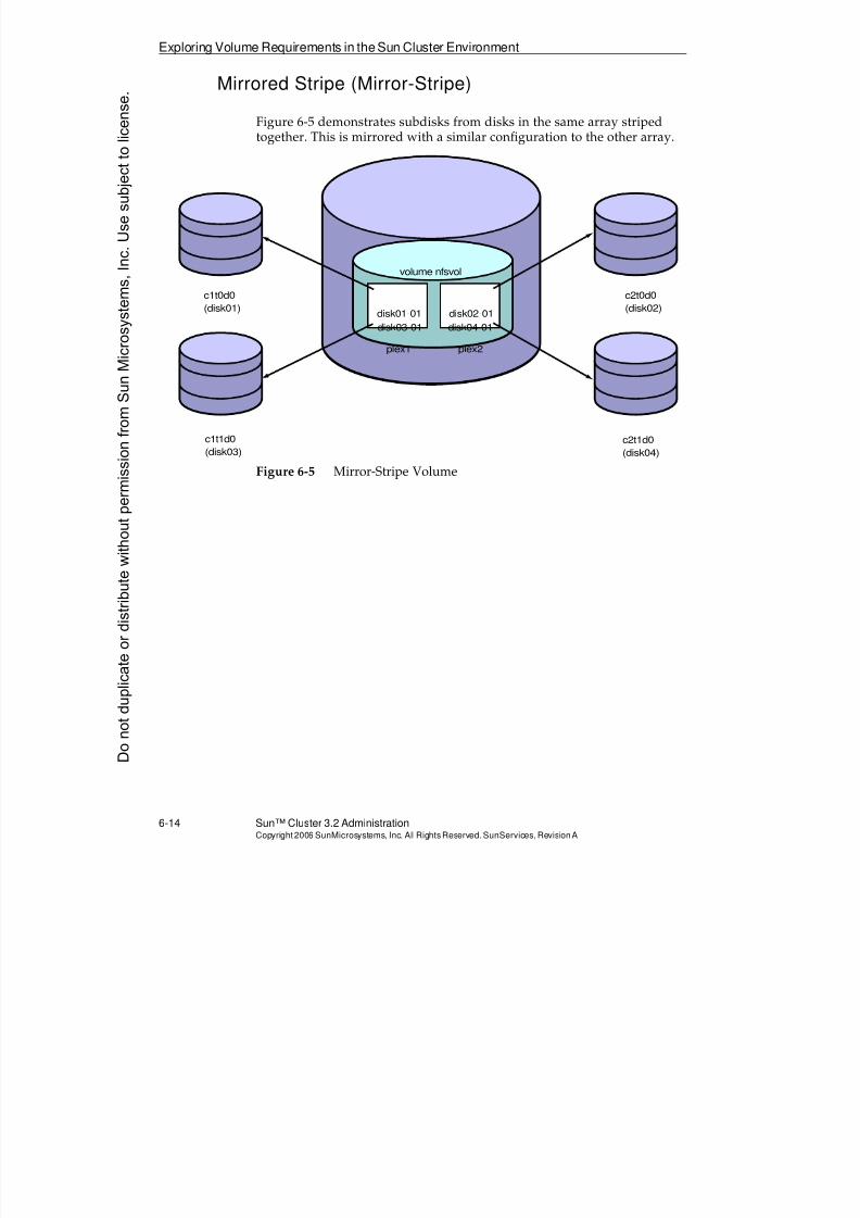
8/4/2019 Sun Cluster 3.2 Administration VC-ES-345
http://slidepdf.com/reader/full/sun-cluster-32-administration-vc-es-345 288/585
Exploring Volume Requirements in the Sun Cluster Environment
6-14 Sun™ Cluster 3.2 AdministrationCopyright2006 SunMicrosystems, Inc. AllRights Reserved.SunServices,RevisionA
Mirrored Stripe (Mirror-Stripe)
Figure 6-5 demonstrates subdisks from disks in the same array stripedtogether. This is mirrored with a similar configuration to the other array.
Figure 6-5 Mirror-Stripe Volume
c1t0d0
(disk01)
c2t0d0
(disk02)
c1t1d0
(disk03)
c2t1d0
(disk04)
disk01-01 disk02-01
plex1 plex2
disk03-01 disk04-01
volume nfsvol
Donotduplicate
ordistributewithoutpermissionfrom SunMicrosystems,Inc.Usesubject
tolicense.
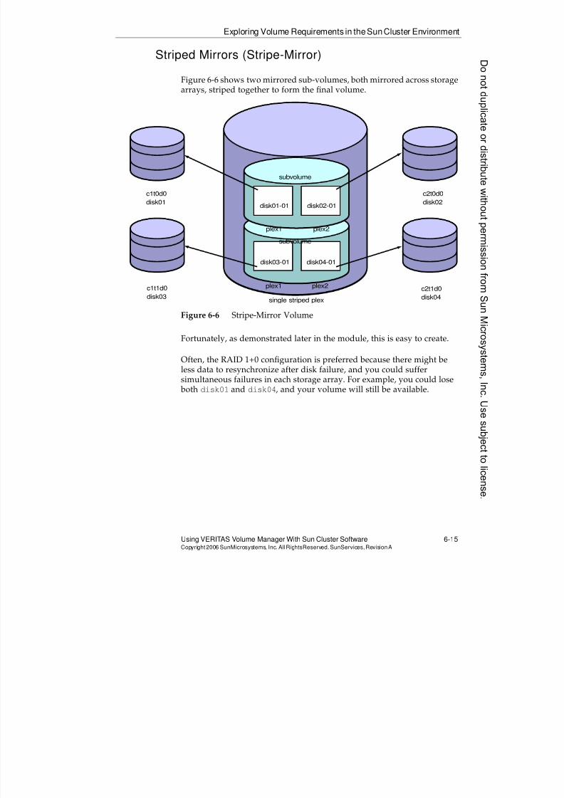
8/4/2019 Sun Cluster 3.2 Administration VC-ES-345
http://slidepdf.com/reader/full/sun-cluster-32-administration-vc-es-345 289/585
Exploring Volume Requirements in theSunCluster Environment
Using VERITAS Volume Manager With Sun Cluster Software 6-15Copyright2006 SunMicrosystems, Inc. AllRightsReserved. SunServices,RevisionA
Striped Mirrors (Stripe-Mirror)
Figure 6-6 shows two mirrored sub-volumes, both mirrored across storagearrays, striped together to form the final volume.
Figure 6-6 Stripe-Mirror Volume
Fortunately, as demonstrated later in the module, this is easy to create.
Often, the RAID 1+0 configuration is preferred because there might beless data to resynchronize after disk failure, and you could suffersimultaneous failures in each storage array. For example, you could lose both disk01 and disk04, and your volume will still be available.
c1t0d0
disk01
c2t0d0
disk02
c1t1d0
disk03
c2t1d0
disk04single striped plex
disk01-01 disk02-01
plex1 plex2
plex1 plex2
disk03-01 disk04-01
subvolume
subvolume
8/4/2019 Sun Cluster 3.2 Administration VC-ES-345
http://slidepdf.com/reader/full/sun-cluster-32-administration-vc-es-345 290/585
Exploring Volume Requirements in the Sun Cluster Environment
6-16 Sun™ Cluster 3.2 AdministrationCopyright2006 SunMicrosystems, Inc. AllRights Reserved.SunServices,RevisionA
Dirty Region Logs for Volumes in the Cluster
Dirty region log (DRL) is an optional feature you can add on a per-volume basis. The DRL is an extra plex for the volume that does not holddata but rather holds bitmaps of which regions of the data might be dirty.
That is, they might need to be resynchronized in the volume after a SolarisOS crash.
DRLs have no effect whatsoever on resynchronization behavior followingdisk failure.
Without a DRL, a mirrored volume must be completely resynchronizedafter a Solaris OS crash. That is because on recovery (on another node, inthe cluster environment), VxVM has no way of knowing which bits ofdata it might have been in the middle of writing when the crash occurred.
With the DRL, VxVM knows exactly which regions of the data marked inthe DRL bitmap might need to be resynchronized. Regions not marked inthe bitmap are known to be clean, and do not need to be resynchronized.
You use a DRL for any large volume in the cluster. The whole purpose ofthe cluster is making everything behave as well as possible after crashes.
Size of DRL
DRLs are small. Use the vxassist command to size them. The size of thelogs that the command chooses depends on the version of VxVM, butmight be, for example, 26 kilobytes (Kbytes) of DRL per 1 Gbyte ofstorage.
If you grow a volume, just delete the DRL, and then use the vxassistcommand to add it back again so that it is sized properly.
Location of DRL
You can put DRL subdisks on the same disk as the data if the volume willnot be heavily written. An example of this is Web data.
For a heavily written volume, performance is better with a DRL on adifferent disk than the data. For example, you could dedicate one disk toholding all the DRLs for all the volumes in the group. They are so smallthat performance on this one disk is still fine.
Donotduplicate
ordistributewithoutpermissionfrom SunMicrosystems,Inc.Usesubject
tolicense.
8/4/2019 Sun Cluster 3.2 Administration VC-ES-345
http://slidepdf.com/reader/full/sun-cluster-32-administration-vc-es-345 291/585
Viewing the Installation and bootdg/rootdgRequirements in the Sun Cluster
Using VERITAS Volume Manager With Sun Cluster Software 6-17Copyright2006 SunMicrosystems, Inc. AllRightsReserved. SunServices,RevisionA
Viewing the Installation and bootdg/rootdgRequirements in the Sun Cluster Environment
The rest of this module is dedicated to general procedures for installing
and administering VxVM in the cluster. It describes both easy automaticways, and more difficult manual ways for meeting the requirementsdescribed in the following list:
q The vxio major number must be identical on all nodes – This is theentry in the /etc/name_to_major file for the vxio device driver. Ifthe major number is not the same on all nodes, the global deviceinfrastructure cannot work on top of VxVM.
q VxVM must be installed on all nodes physically connected to sharedstorage – On non-storage nodes, you can install VxVM if you willuse it to encapsulate and mirror the boot disk.
If not (for example, you might be using Solaris Volume Managersoftware to mirror root storage), then a non-storage node requiresonly that the vxio major number be added to the/etc/name_to_majorfile.
q A license is required on all storage nodes not attached to SunStorEdge A5x00 arrays. If you choose not to install VxVM on a non-storage node you do not need a license for that node.
Requirements for bootdg/rootdg
You can have an optional bootdg (pointing to an actual arbitrary groupname) on VxVM 4.x and above. You will likely have this only if you wantto encapsulate and mirror the OS disk.
8/4/2019 Sun Cluster 3.2 Administration VC-ES-345
http://slidepdf.com/reader/full/sun-cluster-32-administration-vc-es-345 292/585
Viewing the Installation and bootdg/rootdgRequirements in the Sun Cluster
6-18 Sun™ Cluster 3.2 AdministrationCopyright2006 SunMicrosystems, Inc. AllRights Reserved.SunServices,RevisionA
Cluster-Specific Issues When Encapsulating the BootDisk
There are several cluster-specific issues with encapsulating the boot disk.
These caveats all involve the fact that among the file systems beingencapsulated on your boot disk is the /global/.devices/node@#filesystem. The requirements are the following:
q Unique volume name across all nodes for the/global/.devices/node@#volume
q Unique minor number across nodes for the/global/.devices/node@#volume
The reason for these restrictions is that this file system is mounted as aglobal file system. The typical Solaris OS /etc/mnttab logic still demands
that each device and major/minor combination be unique.
If you want to encapsulate the boot disk, you should use the clvxvmutility which automates the correct creation of this volume (with differentvolume names and minor numbers on each node). This is described laterin this module.
DMP Restrictions in Sun Cluster 3.2
In versions of VxVM supported by Sun Cluster 3.2 (VxVM 4.1 and 5.0)you cannot permanently disable the DMP feature. Even if you take stepsto disable DMP, it automatically re-enables itself each time the system is booted.
Having multiple paths from the same node to the same storage undercontrol of VxVM DMP is still not supported. You can:
q Have no multiple paths at all from a node to the same storage
q Have multiple paths from a node under the control of:
q Sun StorEdge Traffic Manager software
q Sun Dynamic Link Manager, for Hitachi storage
q EMC PowerPath software, for EMC storage
Donotduplicate
ordistributewithoutpermissionfrom SunMicrosystems,Inc.Usesubject
tolicense.
8/4/2019 Sun Cluster 3.2 Administration VC-ES-345
http://slidepdf.com/reader/full/sun-cluster-32-administration-vc-es-345 293/585
Viewing the Installation and bootdg/rootdgRequirements in the Sun Cluster
Using VERITAS Volume Manager With Sun Cluster Software 6-19Copyright2006 SunMicrosystems, Inc. AllRightsReserved. SunServices,RevisionA
Installing Supported Multipathing Software
The best strategy is to make sure your multipathed storage systems areunder control of the multipath solution supported by the cluster beforeyou ever even install Sun Cluster software. To review, the installation and
configuration order would be:
1. Install Solaris OS and patches
2. Install and configure any required multipathing software
3. Install and configure Sun Cluster software
4. Install and configure VxVM
8/4/2019 Sun Cluster 3.2 Administration VC-ES-345
http://slidepdf.com/reader/full/sun-cluster-32-administration-vc-es-345 294/585
Installing VxVM in theSun Cluster 3.2 SoftwareEnvironment
6-20 Sun™ Cluster 3.2 AdministrationCopyright2006 SunMicrosystems, Inc. AllRights Reserved.SunServices,RevisionA
Installing VxVM in the Sun Cluster 3.2 SoftwareEnvironment
This section describes the following:
q Using the installer or installvm utilities to install and initializeVxVM 4.1 or 5.0
q Installing the packages by hand
q Using the clvxvm utility to synchronize vxio major numbers and toencapsulate the root disk
q Addressing VxVM cluster-specific issues if you installed VxVM before the cluster was installed
Using the installer or installvmUtility
The VERITAS software comes with two text-based installers, installer(which can install all of the VERITAS products) and installvm (which isspecifically for volume manager). Both of these utilities have thefollowing characteristics:
q They can install the software on multiple servers (multiple nodes) ifrsh/rcp or ssh/scp is enabled between the nodes (or you canchoose to run it separately on each node).
q They will install quite of few packages (30 packages for example, forVxVM 5.0), even if you choose only the required packages. Theseinclude Web servers and Java environments to run the GUI back-ends. This is many more than the minimal software required to runVxVM in the cluster.
q They guide you through entering licenses and initializing thesoftware at the end of the installation.
Donotduplicate
ordistributewithoutpermissionfrom SunMicrosystems,Inc.Usesubject
tolicense.
8/4/2019 Sun Cluster 3.2 Administration VC-ES-345
http://slidepdf.com/reader/full/sun-cluster-32-administration-vc-es-345 295/585
Installing VxVM in the Sun Cluster 3.2Software Environment
Using VERITAS Volume Manager With Sun Cluster Software 6-21Copyright2006 SunMicrosystems, Inc. AllRightsReserved. SunServices,RevisionA
Installing the Packages by Hand
The following are the only VxVM packages required on all the nodes:
q VRTSvxvm
q VRTSvlic
The VxVM 4.1 and 5.0 packages are distributed on the media as .tar.gzfiles. The installer and installvm utilities extract these correctly.
If you want to install VxVM without using the utilities you copy andextract these archives manually and then install them with pkgadd oneach node. You then have to manually use vxinstall to license andinitialize the software.
8/4/2019 Sun Cluster 3.2 Administration VC-ES-345
http://slidepdf.com/reader/full/sun-cluster-32-administration-vc-es-345 296/585
Installing VxVM in theSun Cluster 3.2 SoftwareEnvironment
6-22 Sun™ Cluster 3.2 AdministrationCopyright2006 SunMicrosystems, Inc. AllRights Reserved.SunServices,RevisionA
Example of installvmScreens
The installvm guides you logically through the tasks. The initial screenslook similar to the following:
Veritas Volume Manager 5.0 Installation Program
Copyright (c) 2006 Symantec Corporation. All rights reserved. Symantec, the
Symantec Logo are trademarks or registered trademarks of Symantec Corporation or
its affiliates in the U.S. and other countries. Other names may be trademarks of
their respective owners.
The Licensed Software and Documentation are deemed to be "commercial computer
software" and "commercial computer software documentation" as defined in FAR
Sections 12.212 and DFARS Section 227.7202.
Logs for installvm are being created in /var/tmp/installvm-DTVRAi.
Enter the system names separated by spaces on which to install VxVM: vincent theoInitial system check:
installvm requires that ssh commands used between systems execute without
prompting for passwords or confirmations. If installvm hangs or asks for a login
password or hangs, stop installvm and run it again with the ssh configured for
password free logins, or configure rsh and use the -rsh option.
Checking ssh communication with theo ............................. SunOS 5.10
Checking VxVM installation on vincent ......................... not installed
Checking VxVM installation on theo ............................ not installed
VxVM can be installed without optional packages to conserve disk space.
Additional packages are typically installed to simplify future upgrades.
1) Required Veritas Volume Manager packages - 839 MB required
2) All Veritas Volume Manager packages - 863 MB required
3) Storage Foundation Enterprise packages - 1051 MB required
Select the packages to be installed on all systems? [1-3,q,?] (3)
Donotduplicate
ordistributewithoutpermissionfrom SunMicrosystems,Inc.Usesubject
tolicense.
8/4/2019 Sun Cluster 3.2 Administration VC-ES-345
http://slidepdf.com/reader/full/sun-cluster-32-administration-vc-es-345 297/585
Installing VxVM in the Sun Cluster 3.2Software Environment
Using VERITAS Volume Manager With Sun Cluster Software 6-23Copyright2006 SunMicrosystems, Inc. AllRightsReserved. SunServices,RevisionA
Using the clvxvmUtility
The clvxvm utility automates VxVM cluster-specific configuration,including optional root encapsulation. The clvxvm checks that VxVMitself is already installed and that the VxVM general configuration
(vxinstall, which is automated by the installer and installvmutilities) is complete.
Runningclvxvm initialize
If you choose this option, then clvxvm negotiates a vxio major numberand edits the /etc/name_to_majorfile, if necessary. If it has to modifythe file, then it tells you that you need to reboot.
Runningclvxvm encapsulate
If you choose this option, clvxvm negotiates the vxio major number. Itthen encapsulates your root disk by performing the following tasks:
q It encapsulates your boot disk in a disk group named rootdg, andcreates the bootdg link.
q It gives different volume names for the volumes containing the/global/.devices/node@#file systems on each node.
q It edits the vfstab file for this same volume, replacing the DIDdevice with the original c#t#d#s#. This allows VxVM encapsulation
to properly recognize this is a partition on the OS disk.
q It installs a script to reminor the bootdg on reboot.
q It reboots you into a state where VxVM on your node is fullyoperational. It reboots the first time using -x into non-clusteredmode because the second reboot that is performed by VxVMautomatically takes you back into the cluster.
Note – VxVM itself (not our utilities) still puts in a nologging option forthe root file system when you encapsulate. This is a leftover from an old
problem that has been fixed. You must remove the nologging optionfrom /etc/vfstab manually and reboot one more time.
8/4/2019 Sun Cluster 3.2 Administration VC-ES-345
http://slidepdf.com/reader/full/sun-cluster-32-administration-vc-es-345 298/585
Installing VxVM in theSun Cluster 3.2 SoftwareEnvironment
6-24 Sun™ Cluster 3.2 AdministrationCopyright2006 SunMicrosystems, Inc. AllRights Reserved.SunServices,RevisionA
Manually Using vxdiskadm to Encapsulate the OS Disk
Use the following steps to make boot-disk encapsulation work correctlyon the cluster. You should use clvxvm encapsulate to automate all ofthis, however this information is given for completeness:
1. Give a different name for the root disk on each node. Do not use thedefault disk name on each node.
The result is that the volume name for the/global/.devices/node@#file system is different on each node.
2. Make sure you do not enter any shared disk storage drives in thebootdg.
3. Before you reboot manually, put back the normal/dev/dsk/c#t#d#s# and /dev/rdsk/c#t#d#s# on the line in the/etc/vfstab file for the /global/.devices/node@# file system.
Without making this change, VxVM cannot figure out that it mustedit that line after the reboot to put in the VxVM volume name.
4. Reboot with boot -x. VxVM arranges a second reboot after thatwhich brings you back into the cluster.
5. That second reboot fails on all but one of the nodes because of theconflict in minor numbers for bootdg (the conflict is really just forthe /global/.devices/node@#volume).
On those nodes, give the root password to go into single user mode.Use the following command to fix the problem:
# vxdg reminor bootdg 50*nodeid
For example, use 50 for Node 1, 100 for Node 2, and so forth. Thisprovides a unique set of minor numbers for each node.
6. Reboot the nodes for which you had to repair the minor numbers.
Configuring a Pre-Existing VxVM for Sun Cluster 3.2Software
The last possibility is that you have a potential Sun Cluster 3.2 softwarenode where the proper version of VxVM was already installed andinitialized before the Sun Cluster environment was installed. The followingsubsections describe how to provision your VxVM to deal with thecluster-specific issues mentioned on the previous pages. They assume youwill deal with these issues before you install the Sun Cluster software.
Donotduplicate
ordistributewithoutpermissionfrom SunMicrosystems,Inc.Usesubject
tolicense.
8/4/2019 Sun Cluster 3.2 Administration VC-ES-345
http://slidepdf.com/reader/full/sun-cluster-32-administration-vc-es-345 299/585
Installing VxVM in the Sun Cluster 3.2Software Environment
Using VERITAS Volume Manager With Sun Cluster Software 6-25Copyright2006 SunMicrosystems, Inc. AllRightsReserved. SunServices,RevisionA
Fixing thevxioMajor Number
If you need to change the vxio major number to make it agree with theother nodes, do the following:
1. Manually edit the /etc/name_to_majorfile.
2. Unmirror and unencapsulate the root disk, if it is encapsulated.
3. Reboot.
4. Reencapsulate and remirror the boot disk, if desired.
Fixing the/globaldevicesVolume Name and Minor Number
If you are still at a point before cluster installation, you need to have a/globaldevices placeholder file system or at least a correctly sizeddevice ready for cluster installation.
If this is on a volume manager device:
1. Rename the volume if it has the same name as the /globaldevicesor /global/.devices/node@#volume of any other node. Youmight need to manually edit the /etc/vfstab file.
2. Perform a reminor operation on the rootdg if it is using the same setof minor numbers as another node. Follow the same procedure asStep 5 on page 6-24.
8/4/2019 Sun Cluster 3.2 Administration VC-ES-345
http://slidepdf.com/reader/full/sun-cluster-32-administration-vc-es-345 300/585
Creating Shared Disk Groups and Volumes
6-26 Sun™ Cluster 3.2 AdministrationCopyright2006 SunMicrosystems, Inc. AllRights Reserved.SunServices,RevisionA
Creating Shared Disk Groups and Volumes
The examples in this section are not trying to exhaustively cover all thepossible ways of initializing disks and creating volumes. Rather, these aredemonstrations of some simple ways of initializing disks, populating diskgroups, and creating the mirrored configurations described earlier in themodule.
Listing Available Disks
The following command lists all of the disks visible to VxVM:
vincent:/# vxdisk -o alldgs list
DEVICE TYPE DISK GROUP STATUS
c0t0d0s2 auto:sliced rootdg_1 rootdg online
c0t1d0s2 auto:none - - online invalid
c1t0d0s2 auto:none - - online invalid
c1t1d0s2 auto:none - - online invalid
c1t2d0s2 auto:none - - online invalid
c1t3d0s2 auto:none - - online invalid
c1t8d0s2 auto:none - - online invalid
c1t9d0s2 auto:none - - online invalid
c1t10d0s2 auto:none - - online invalid
c1t11d0s2 auto:none - - online invalid
c2t0d0s2 auto:none - - online invalid
c2t1d0s2 auto:none - - online invalid
c2t2d0s2 auto:none - - online invalid
c2t3d0s2 auto:none - - online invalid
c2t8d0s2 auto:none - - online invalid
c2t9d0s2 auto:none - - online invalid
c2t10d0s2 auto:none - - online invalid
The command vxdisk list with the option -o alldgs scans every diskto see if there is any disk group information, even about disk groups notcurrently imported on this node. In this output you can see that there isno disk group information configured on other disk other than the first
disk.
Disks with the invalid state are not yet initialized by VxVM.
Donotduplicate
ordistributewithoutpermissionfrom SunMicrosystems,Inc.Usesubject
tolicense.
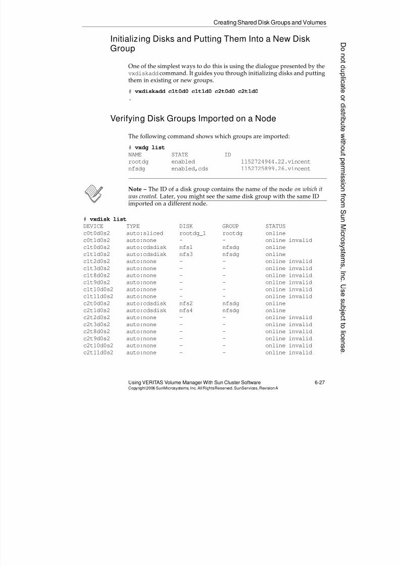
8/4/2019 Sun Cluster 3.2 Administration VC-ES-345
http://slidepdf.com/reader/full/sun-cluster-32-administration-vc-es-345 301/585
Creating Shared Disk Groups and Volumes
Using VERITAS Volume Manager With Sun Cluster Software 6-27Copyright2006 SunMicrosystems, Inc. AllRightsReserved. SunServices,RevisionA
Initializing Disks and Putting Them Into a New DiskGroup
One of the simplest ways to do this is using the dialogue presented by thevxdiskadd
command. It guides you through initializing disks and puttingthem in existing or new groups.
# vxdiskadd c1t0d0 c1t1d0 c2t0d0 c2t1d0
.
Verifying Disk Groups Imported on a Node
The following command shows which groups are imported:
# vxdg list
NAME STATE IDrootdg enabled 1152724944.22.vincent
nfsdg enabled,cds 1152725899.26.vincent
Note – The ID of a disk group contains the name of the node on which itwas created. Later, you might see the same disk group with the same IDimported on a different node.
# vxdisk list
DEVICE TYPE DISK GROUP STATUS
c0t0d0s2 auto:sliced rootdg_1 rootdg online
c0t1d0s2 auto:none - - online invalid
c1t0d0s2 auto:cdsdisk nfs1 nfsdg online
c1t1d0s2 auto:cdsdisk nfs3 nfsdg online
c1t2d0s2 auto:none - - online invalid
c1t3d0s2 auto:none - - online invalid
c1t8d0s2 auto:none - - online invalid
c1t9d0s2 auto:none - - online invalid
c1t10d0s2 auto:none - - online invalid
c1t11d0s2 auto:none - - online invalid
c2t0d0s2 auto:cdsdisk nfs2 nfsdg online
c2t1d0s2 auto:cdsdisk nfs4 nfsdg online
c2t2d0s2 auto:none - - online invalid
c2t3d0s2 auto:none - - online invalid
c2t8d0s2 auto:none - - online invalid
c2t9d0s2 auto:none - - online invalid
c2t10d0s2 auto:none - - online invalid
c2t11d0s2 auto:none - - online invalid
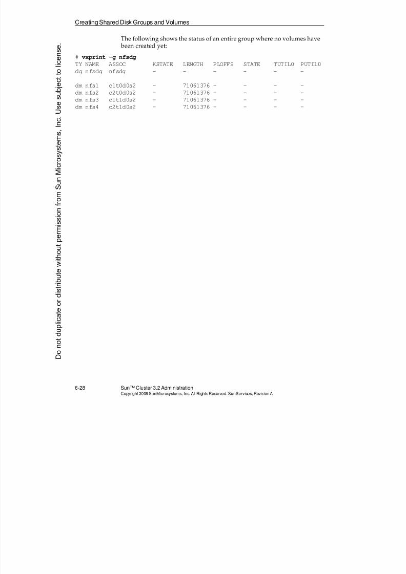
8/4/2019 Sun Cluster 3.2 Administration VC-ES-345
http://slidepdf.com/reader/full/sun-cluster-32-administration-vc-es-345 302/585
Creating Shared Disk Groups and Volumes
6-28 Sun™ Cluster 3.2 AdministrationCopyright2006 SunMicrosystems, Inc. AllRights Reserved.SunServices,RevisionA
The following shows the status of an entire group where no volumes have been created yet:
# vxprint -g nfsdg
TY NAME ASSOC KSTATE LENGTH PLOFFS STATE TUTIL0 PUTIL0
dg nfsdg nfsdg - - - - - -
dm nfs1 c1t0d0s2 - 71061376 - - - -
dm nfs2 c2t0d0s2 - 71061376 - - - -
dm nfs3 c1t1d0s2 - 71061376 - - - -
dm nfs4 c2t1d0s2 - 71061376 - - - -
Donotduplicate
ordistributewithoutpermissionfrom SunMicrosystems,Inc.Usesubject
tolicense.
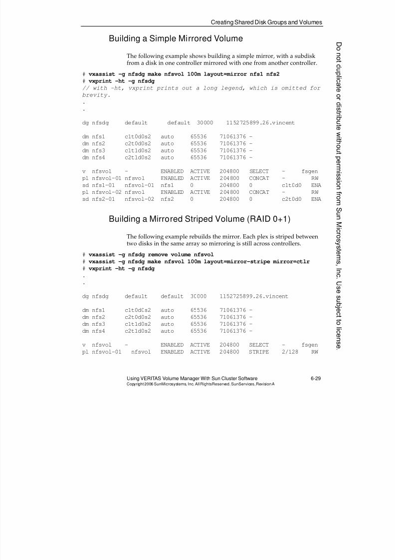
8/4/2019 Sun Cluster 3.2 Administration VC-ES-345
http://slidepdf.com/reader/full/sun-cluster-32-administration-vc-es-345 303/585
Creating Shared Disk Groups and Volumes
Using VERITAS Volume Manager With Sun Cluster Software 6-29Copyright2006 SunMicrosystems, Inc. AllRightsReserved. SunServices,RevisionA
Building a Simple Mirrored Volume
The following example shows building a simple mirror, with a subdiskfrom a disk in one controller mirrored with one from another controller.
# vxassist -g nfsdg make nfsvol 100m layout=mirror nfs1 nfs2# vxprint -ht -g nfsdg
// with -ht, vxprint prints out a long legend, which is omitted for
brevity.
.
.
dg nfsdg default default 30000 1152725899.26.vincent
dm nfs1 c1t0d0s2 auto 65536 71061376 -
dm nfs2 c2t0d0s2 auto 65536 71061376 -
dm nfs3 c1t1d0s2 auto 65536 71061376 -dm nfs4 c2t1d0s2 auto 65536 71061376 -
v nfsvol - ENABLED ACTIVE 204800 SELECT - fsgen
pl nfsvol-01 nfsvol ENABLED ACTIVE 204800 CONCAT - RW
sd nfs1-01 nfsvol-01 nfs1 0 204800 0 c1t0d0 ENA
pl nfsvol-02 nfsvol ENABLED ACTIVE 204800 CONCAT - RW
sd nfs2-01 nfsvol-02 nfs2 0 204800 0 c2t0d0 ENA
Building a Mirrored Striped Volume (RAID 0+1)
The following example rebuilds the mirror. Each plex is striped betweentwo disks in the same array so mirroring is still across controllers.
# vxassist -g nfsdg remove volume nfsvol
# vxassist -g nfsdg make nfsvol 100m layout=mirror-stripe mirror=ctlr
# vxprint -ht -g nfsdg
.
.
dg nfsdg default default 30000 1152725899.26.vincent
dm nfs1 c1t0d0s2 auto 65536 71061376 -
dm nfs2 c2t0d0s2 auto 65536 71061376 -
dm nfs3 c1t1d0s2 auto 65536 71061376 -
dm nfs4 c2t1d0s2 auto 65536 71061376 -
v nfsvol - ENABLED ACTIVE 204800 SELECT - fsgen
pl nfsvol-01 nfsvol ENABLED ACTIVE 204800 STRIPE 2/128 RW
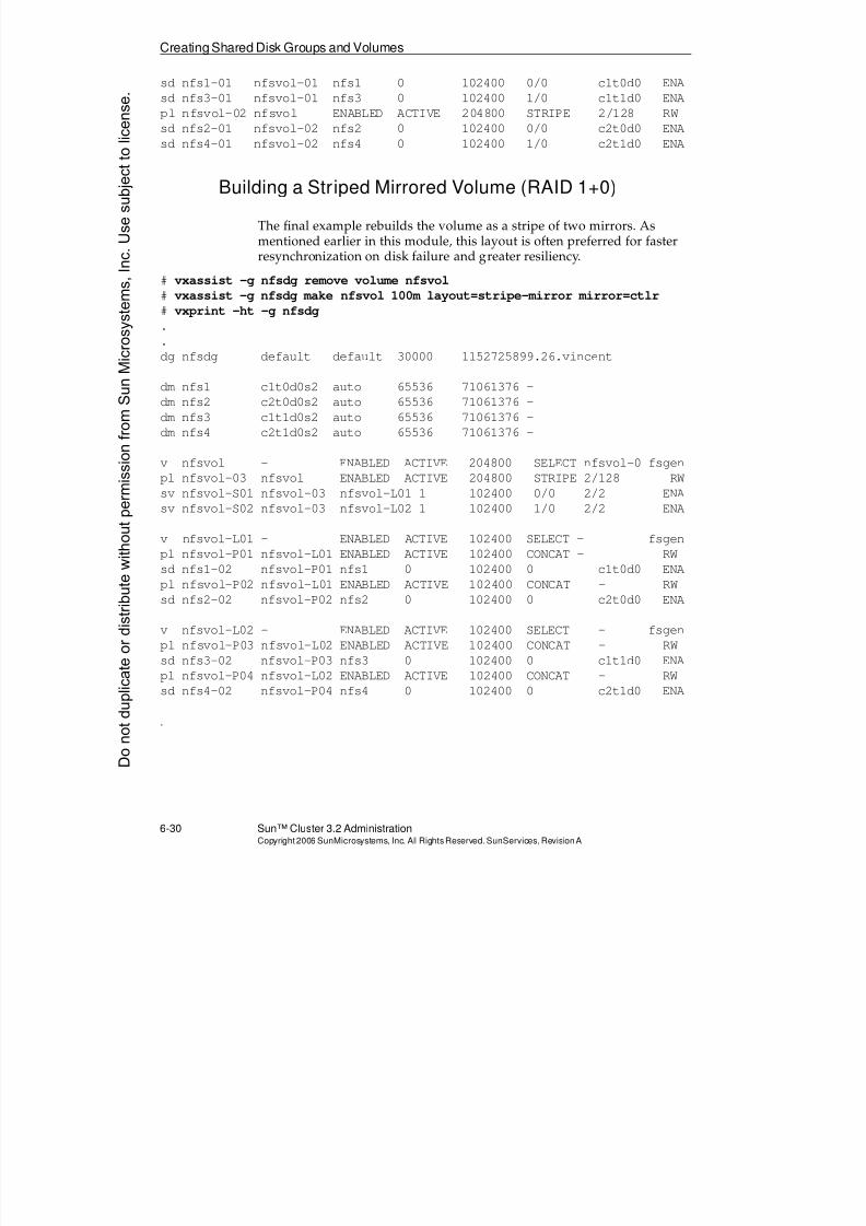
8/4/2019 Sun Cluster 3.2 Administration VC-ES-345
http://slidepdf.com/reader/full/sun-cluster-32-administration-vc-es-345 304/585
Creating Shared Disk Groups and Volumes
6-30 Sun™ Cluster 3.2 AdministrationCopyright2006 SunMicrosystems, Inc. AllRights Reserved.SunServices,RevisionA
sd nfs1-01 nfsvol-01 nfs1 0 102400 0/0 c1t0d0 ENA
sd nfs3-01 nfsvol-01 nfs3 0 102400 1/0 c1t1d0 ENA
pl nfsvol-02 nfsvol ENABLED ACTIVE 204800 STRIPE 2/128 RW
sd nfs2-01 nfsvol-02 nfs2 0 102400 0/0 c2t0d0 ENA
sd nfs4-01 nfsvol-02 nfs4 0 102400 1/0 c2t1d0 ENA
Building a Striped Mirrored Volume (RAID 1+0)
The final example rebuilds the volume as a stripe of two mirrors. Asmentioned earlier in this module, this layout is often preferred for fasterresynchronization on disk failure and greater resiliency.
# vxassist -g nfsdg remove volume nfsvol
# vxassist -g nfsdg make nfsvol 100m layout=stripe-mirror mirror=ctlr
# vxprint -ht -g nfsdg
..
dg nfsdg default default 30000 1152725899.26.vincent
dm nfs1 c1t0d0s2 auto 65536 71061376 -
dm nfs2 c2t0d0s2 auto 65536 71061376 -
dm nfs3 c1t1d0s2 auto 65536 71061376 -
dm nfs4 c2t1d0s2 auto 65536 71061376 -
v nfsvol - ENABLED ACTIVE 204800 SELECT nfsvol-0 fsgen
pl nfsvol-03 nfsvol ENABLED ACTIVE 204800 STRIPE 2/128 RW
sv nfsvol-S01 nfsvol-03 nfsvol-L01 1 102400 0/0 2/2 ENAsv nfsvol-S02 nfsvol-03 nfsvol-L02 1 102400 1/0 2/2 ENA
v nfsvol-L01 - ENABLED ACTIVE 102400 SELECT - fsgen
pl nfsvol-P01 nfsvol-L01 ENABLED ACTIVE 102400 CONCAT - RW
sd nfs1-02 nfsvol-P01 nfs1 0 102400 0 c1t0d0 ENA
pl nfsvol-P02 nfsvol-L01 ENABLED ACTIVE 102400 CONCAT - RW
sd nfs2-02 nfsvol-P02 nfs2 0 102400 0 c2t0d0 ENA
v nfsvol-L02 - ENABLED ACTIVE 102400 SELECT - fsgen
pl nfsvol-P03 nfsvol-L02 ENABLED ACTIVE 102400 CONCAT - RW
sd nfs3-02 nfsvol-P03 nfs3 0 102400 0 c1t1d0 ENApl nfsvol-P04 nfsvol-L02 ENABLED ACTIVE 102400 CONCAT - RW
sd nfs4-02 nfsvol-P04 nfs4 0 102400 0 c2t1d0 ENA
.
Donotduplicate
ordistributewithoutpermissionfrom SunMicrosystems,Inc.Usesubject
tolicense.
8/4/2019 Sun Cluster 3.2 Administration VC-ES-345
http://slidepdf.com/reader/full/sun-cluster-32-administration-vc-es-345 305/585
Examining Hot Relocation
Using VERITAS Volume Manager With Sun Cluster Software 6-31Copyright2006 SunMicrosystems, Inc. AllRightsReserved. SunServices,RevisionA
Examining Hot Relocation
Hot relocation is controlled by the vxrelocd daemon, which is started bydefault after you initialize the volume manager.
When a disk that is a component of a mirrored volume breaks, VxVMlooks for space to substitute for the broken half of the mirror. If one largedisk breaks, VxVM can concatenate many new subdisks from other disksin the diskgroup to recreate the broken plex. It never uses any disk spacefrom disks in the surviving plex.
The SPAREand NOHOTUSEFlags
Under normal hot relocation, disks can be marked with one of the twofollowing flags, but not both:
q SPARE
Disks marked with the SPARE flag are the preferred disks to use forhot relocation. These disks can still be used to build normal volumes.
q NOHOTUSE
Disks marked with the NOHOTUSE flag are excluded fromconsideration for hot relocation.
In the following example, disk nfs2 is set as a preferred disk for hotrelocation, and disk nfs1 is excluded from hot relocation usage:
# vxedit -g nfsdg set spare=on nfs2
# vxedit -g nfsdg set nohotuse=on nfs1
The flag settings are visible in the output of the vxdisk list andvxprint commands.
8/4/2019 Sun Cluster 3.2 Administration VC-ES-345
http://slidepdf.com/reader/full/sun-cluster-32-administration-vc-es-345 306/585
Registering VxVM Disk Groups
6-32 Sun™ Cluster 3.2 AdministrationCopyright2006 SunMicrosystems, Inc. AllRights Reserved.SunServices,RevisionA
Registering VxVM Disk Groups
After you create a new VxVM disk group and volumes, you mustmanually register the disk group using either the clsetup utility or thecldevicegroup create command for the disk group to be managed bythe cluster.
When a VxVM disk group is registered in the Sun Cluster softwareenvironment, it is referred to as a device group.
Until a VxVM disk group is registered, the cluster does not detect it.While you can build volumes and perform all normal VxVMadministration tasks, you are not able to use the volume manager devicesin the cluster.
If you create a new volume or delete a volume in a VxVM disk group thatis already registered with the cluster, you must synchronize the diskdevice group by using clsetup. Such configuration changes includeadding or removing volumes and changing the group, owner, orpermissions of existing volumes. Synchronization after volumes arecreated or deleted ensures that the global namespace is in the correct state.
The following example shows a disk group that is known to VxVM, butnot yet known to the cluster. cldg is just the short form ofcldevicegroup.
# vxdg listNAME STATE ID
rootdg enabled 1152724944.22.vincent
nfsdg enabled,cds 1152725899.26.vincent
# cldevicegroup show
# cldg status
Cluster Device Groups ===
--- Device Group Status ---
Device Group Name Primary Secondary Status
----------------- ------- --------- ------
Donotduplicate
ordistributewithoutpermissionfrom SunMicrosystems,Inc.Usesubject
tolicense.
8/4/2019 Sun Cluster 3.2 Administration VC-ES-345
http://slidepdf.com/reader/full/sun-cluster-32-administration-vc-es-345 307/585
RegisteringVxVM Disk Groups
Using VERITAS Volume Manager With Sun Cluster Software 6-33Copyright2006 SunMicrosystems, Inc. AllRightsReserved. SunServices,RevisionA
Using the cldg createCommand to Register DiskGroups
The following command registers a VxVM disk group as a cluster device
group. You must type this command on the node currently importing the group.# cldg create -t vxvm -n vincent,theo -p preferenced=true \
-p failback=false nfsdg
This command uses the following parameters:
q The -n option (node list) should list all the nodes and only the nodesphysically connected to the disk group’s disks.
q The preferenced=true/false affects whether the nodelistindicates an order of failover preference. On a two node cluster thisoption is only meaningful if failback is true.
q The failback=true/false affects whether a preferred node takes back its device group when it joins the cluster. The default value isfalse. If it is true, it only works if preferenced is also set to true.
Using the clsetup Command to Register Disk Groups
The clsetup utility can guide you through the previous options in amenu-driven environment. From the main menus, selecting Menu
Option 5 (Device Groups and Volumes) gives you the following submenu:*** Device Groups Menu ***
Please select from one of the following options:
1) Register a VxVM disk group as a device group
2) Synchronize volume information for a VxVM device group
3) Unregister a VxVM device group
4) Add a node to a VxVM device group
5) Remove a node from a VxVM device group
6) Change key properties of a device group
7) Set a VxVM disk group as a local disk group8) Reset a local disk group to a VxVM disk group
?) Help
q) Return to the Main Menu
8/4/2019 Sun Cluster 3.2 Administration VC-ES-345
http://slidepdf.com/reader/full/sun-cluster-32-administration-vc-es-345 308/585
Registering VxVM Disk Groups
6-34 Sun™ Cluster 3.2 AdministrationCopyright2006 SunMicrosystems, Inc. AllRights Reserved.SunServices,RevisionA
Viewing and Controlling Registered Device Groups
Use the cldg show command to show the properties of a device group(or all device groups). Use cldg status to see the status.
# cldg show nfsdg
Device Groups ===
Device Group Name: nfsdg
Type: VxVM
failback: false
Node List: vincent, theo
preferenced: true
numsecondaries: 1
diskgroup name: nfsdg
# cldg status
Cluster Device Groups ===
--- Device Group Status ---
Device Group Name Primary Secondary Status
----------------- ------- --------- ------
nfsdg vincent theo Online
Note – By default, even if there are more than two nodes in the node listfor a device group, only one node shows up as secondary. If the primaryfails, the secondary becomes primary and another (spare) node becomessecondary.
The numsecondaries=# parameter is used on the cldg command line toallow more than one secondary.
When VxVM disk groups are registered as Sun Cluster software device
groups and have the status Online, never use the vxdg import and vxdgdeport commands to control ownership of the disk group. This causesthe cluster to treat the device group as failed.
Instead, use the following command syntax to control disk groupownership:
# cldg switch -n node_to_switch_to nfsdgDonotduplicate
ordistributewithoutpermissionfrom SunMicrosystems,Inc.Usesubject
tolicense.
8/4/2019 Sun Cluster 3.2 Administration VC-ES-345
http://slidepdf.com/reader/full/sun-cluster-32-administration-vc-es-345 309/585
Managing VxVM Device Groups
Using VERITAS Volume Manager With Sun Cluster Software 6-35Copyright2006 SunMicrosystems, Inc. AllRightsReserved. SunServices,RevisionA
Managing VxVM Device Groups
The cldevicegroup (cldg) command can be used to perform cluster-specific changes to VxVM device groups.
Resynchronizing Device Groups
After a VxVM device group is registered with the cluster, it must beresynchronized any time a new volume is created or deleted in the diskgroup. This instructs the Sun Cluster software to scan the disk group and build and remove the appropriate global device files:
# cldg sync nfsdg
Making Other Changes to Device Groups
The properties of existing VxVM device groups can also be changed. Forexample, the failback and preferenced properties of a group can bemodified after it is registered.
# cldg set -p preferenced=false -p failback=false nfsdg
Note – If you do this command on the node that is not primary for thedevice group, you may get a warning that makes it seem like thecommand failed. It is just a warning, and the command succeeds.
Putting a Device Group Offline and Back Online
You can take a VxVM device group out of service, as far as the cluster isconcerned, for emergency repairs.
To put the device group offline all of the VxVM volumes must be unused
(unmounted or otherwise not open). You then issue the followingcommand, from any node:
# cldg offline nfsdg
You will rarely take a device group out of service because almost allrepairs can still be done while the device group is in service.
8/4/2019 Sun Cluster 3.2 Administration VC-ES-345
http://slidepdf.com/reader/full/sun-cluster-32-administration-vc-es-345 310/585
Managing VxVM Device Groups
6-36 Sun™ Cluster 3.2 AdministrationCopyright2006 SunMicrosystems, Inc. AllRights Reserved.SunServices,RevisionA
Type the following command to put the device group online on the firstnode in the list:
# cldg online nfsdg
Alternatively, you can choose exactly which node will become the device
group primary.
# cldg switch -n theo nfsdg
Note – You do not need to perform both commands. One or the other willdo.
Donotduplicate
ordistributewithoutpermissionfrom SunMicrosystems,Inc.Usesubject
tolicense.
8/4/2019 Sun Cluster 3.2 Administration VC-ES-345
http://slidepdf.com/reader/full/sun-cluster-32-administration-vc-es-345 311/585
Using Global and Failover File Systems on VxVM Volumes
Using VERITAS Volume Manager With Sun Cluster Software 6-37Copyright2006 SunMicrosystems, Inc. AllRightsReserved. SunServices,RevisionA
Using Global and Failover File Systems on VxVM Volumes
Sun Cluster 3.2 supports running data services on the following categoriesof file systems:
q Global file systems – Accessible to all cluster nodes simultaneously,even those not physically connected to the storage
q Failover file systems – Mounted only on the node running the failoverdata service, which must be physically connected to the storage
UFS and VxFS are two file system types that can be used as either globalor failover file systems. These examples and the exercises assume you areusing UFS.
Note – There is a convention that the mount point for global file systems besomewhere underneath the /global directory. This is just a convention.
Creating File Systems
The distinction between a global and a failover file system is not made atthe time of file system creation. Use newfs as normal to create a UFS filesystem for the cluster on a volume in a registered disk group:
# newfs /dev/vx/rdsk/nfsdg/nfsvol
Mounting File Systems
For UFS or VxFS, the distinction between a global and a failover filesystem is made in the /etc/vfstabmount-at-boot and options columns.
A global file system entry should look similar to the following, and itshould be identical on all nodes (including nodes not physically
connected to the storage):
/dev/vx/dsk/nfsdg/nfsvol /dev/vx/rdsk/nfsdg/nfsvol /global/nfs ufs 2 yes global
A local failover file system entry looks like the following, and it should beidentical on all nodes who may run services which access the file system(can only be nodes physically connected to the storage):
/dev/vx/dsk/nfsdg/nfsvol /dev/vx/rdsk/nfsdg/nfsvol /localnfs ufs 2 no -
8/4/2019 Sun Cluster 3.2 Administration VC-ES-345
http://slidepdf.com/reader/full/sun-cluster-32-administration-vc-es-345 312/585
Using Global and Failover File Systems on VxVM Volumes
6-38 Sun™ Cluster 3.2 AdministrationCopyright2006 SunMicrosystems, Inc. AllRights Reserved.SunServices,RevisionA
Note – The logging option is the default for all OS versions supportedwith Sun Cluster 3.2. You do not need to specify it explicitly.
Donotduplicate
ordistributewithoutpermissionfrom SunMicrosystems,Inc.Usesubject
tolicense.
8/4/2019 Sun Cluster 3.2 Administration VC-ES-345
http://slidepdf.com/reader/full/sun-cluster-32-administration-vc-es-345 313/585
Mirroring the Boot Disk With VxVM
Using VERITAS Volume Manager With Sun Cluster Software 6-39Copyright2006 SunMicrosystems, Inc. AllRightsReserved. SunServices,RevisionA
Mirroring the Boot Disk With VxVM
If you have encapsulated your boot drive with VxVM, mirroring the bootdrive is a simple procedure that can be undertaken any time while thecluster is online, without any reboot. To mirror the boot drive, completethe following steps:
1. Initialize and add another local drive to bootdg, if this has not beendone yet. This drive must be at least as big as the boot drive. Givethe drive the VxVM logical name rootmir, for example. This is doneas part of the vxdiskadd dialogue.
Make sure that you do not make the disk a CDS disk (choosesliced).
# vxdiskadd c0t8d0
2. Use the vxmirror command, or the vxdiskadmMirror volumes on adisk option to mirror all the volumes on the boot drive.
Caution – Do not mirror each volume separately with vxassist. Thisleaves you in a state that the mirrored drive cannot be unencapsulated.That is, if you ever need to unencapsulate the second disk you will not beable to.
If you mirror the root drive correctly as shown, the second drive can also be unencapsulated. That is because correct restricted subdisks are laiddown onto the new drive. These can later be turned into regular Solaris
OS partitions because they are on cylinder boundaries.
# vxmirror -g bootdg rootdg_1 rootmir
.
.
3. The previous command also creates aliases for both the original rootpartition and the new mirror. You need to manually set your boot-device variable so you can boot off both the original and the mirror.
# eeprom|grep vx
devalias vx-rootdg_1 /pci@1f,4000/scsi@3/disk@0,0:a
devalias vx-rootmir /pci@1f,4000/scsi@3/disk@8,0:a
# eeprom boot-device="vx-rootdg_1 vx-rootmir"
4. Verify that the system has been instructed to use these device aliaseson boot:
# eeprom|grep use-nvramrc
use-nvramrc?=true
8/4/2019 Sun Cluster 3.2 Administration VC-ES-345
http://slidepdf.com/reader/full/sun-cluster-32-administration-vc-es-345 314/585
ZFS as Failover File System Only
6-40 Sun™ Cluster 3.2 AdministrationCopyright2006 SunMicrosystems, Inc. AllRights Reserved.SunServices,RevisionA
ZFS as Failover File System Only
In the initial release of Sun Cluster 3.2 ZFS is available as a failover filesystem only. You will be able to store data only for failover applications(not scalable applications), as such, you will be able to run theapplications only on nodes physically connected to the storage.
ZFS Includes Volume Management Layer
When you use ZFS, you will generally not need any other softwarevolume manager (neither VxVM nor Solaris Volume Manager), nor willyou need to perform any cluster device group management.
ZFS automatically manages its storage in units called zpools. The zpool
layer provides optional data protection in the form of mirroring or raidz (aZFS-specific variation of RAID 5).
Within a zpool you can build any number of file systems. All the filesystems in a pool share all of the storage in the pool. With ZFS, you neverneed to worry about space available in a particular file system. Just growthe pool at any time, and the space will automatically be available to allthe filesystems within.
ZFS Removes Need for /etc/vfstabEntries
When ZFS file systems are created within a pool, the configurationdatabase that ZFS automatically maintains within the pool contains themount information. You never need to create vfstab entries.
Example: Creating a Mirrored Pool and SomeFilesystems
Even in the cluster, you use traditional disk paths (not DID devices) ascomponents of pools. The pools can still fail over even if the paths havedifferent names on a different node (the model is precisely analogous tohow VxVM has always automatically discovered disk groups):
vincent:/# zpool create marcpool mirror c1t0d0 c2t0d0
vincent:/# zpool status
pool: marcpoolDonotduplicate
ordistributewithoutpermissionfrom SunMicrosystems,Inc.Usesubject
tolicense.

8/4/2019 Sun Cluster 3.2 Administration VC-ES-345
http://slidepdf.com/reader/full/sun-cluster-32-administration-vc-es-345 315/585
ZFS as Failover File System Only
Using VERITAS Volume Manager With Sun Cluster Software 6-41Copyright2006 SunMicrosystems, Inc. AllRightsReserved. SunServices,RevisionA
state: ONLINE
scrub: none requested
config:
NAME STATE READ WRITE CKSUM
marcpool ONLINE 0 0 0
mirror ONLINE 0 0 0
c1t0d0 ONLINE 0 0 0
c2t0d0 ONLINE 0 0 0
errors: No known data errors
Now we can create filesystems that occupy the pool. ZFS automaticallycreates mount points and mounts the file systems. You never even need tomake /etc/vfstab entries.
vincent:/# zfs create marcpool/myfs1
vincent:/# zfs create marcpool/myfs2
vincent:/# zfs list
NAME USED AVAIL REFER MOUNTPOINT
marcpool 136K 33.2G 27.5K /marcpool
marcpool/myfs1 24.5K 33.2G 24.5K /marcpool/myfs1
marcpool/myfs2 24.5K 33.2G 24.5K /marcpool/myfs2
vincent:/# df -k
.
.
marcpool 34836480 27 34836343 1% /marcpool
marcpool/myfs1 34836480 24 34836343 1% /marcpool/myfs1
marcpool/myfs2 34836480 24 34836343 1% /marcpool/myfs2
The mount points are defaulted to / poolname/fsname, but you canchange them to whatever you want:
vincent:/# zfs set mountpoint=/oracle marcpool/myfs1
vincent:/# zfs set mountpoint=/shmoracle marcpool/myfs2
vincent:/# df -k |grep pool
marcpool 34836480 26 34836332 1% /marcpool
marcpool/myfs1 34836480 24 34836332 1% /oraclemarcpool/myfs2 34836480 24 34836332 1% /shmoracle
Note – Module 9 includes an exercise to create a zpool and zfs filesystem,and to use HAStoragePlus to make the pool and all its zfs filesystems failover.
8/4/2019 Sun Cluster 3.2 Administration VC-ES-345
http://slidepdf.com/reader/full/sun-cluster-32-administration-vc-es-345 316/585
Exercise: Configuring Volume Management
6-42 Sun™ Cluster 3.2 AdministrationCopyright2006 SunMicrosystems, Inc. AllRights Reserved.SunServices,RevisionA
Exercise: Configuring Volume Management
In this exercise, you complete the following tasks:
q Task 1 – Selecting Disk Drives
q Task 2 – Using pkgadd to Install and Initialize VxVM Software (onAll Storage Nodes)
q Task 3 – Using clvxvm to Verify the vxio Major Number
q Task 4 – Adding vxio on Any Non-Storage Node on Which YouHave Not Installed VxVM
q Task 5 – Rebooting All Nodes
q Task 6 – Configuring Demonstration Volumes
q Task 7 – Registering Demonstration Disk Groups
q Task 8 – Creating a Global nfs File System
q Task 9 – Creating a Global web File System
q Task 10 – Testing Global File Systems
q Task 11 – Managing Disk Device Groups
q Task 12 (Optional) – Viewing and Managing VxVM Device GroupsUsing Sun Cluster Manager
q Task 13 (Optional) – Encapsulating the Boot Disk on a Cluster Node
Donotduplicate
ordistributewithoutpermissionfrom SunMicrosystems,Inc.Usesubject
tolicense.
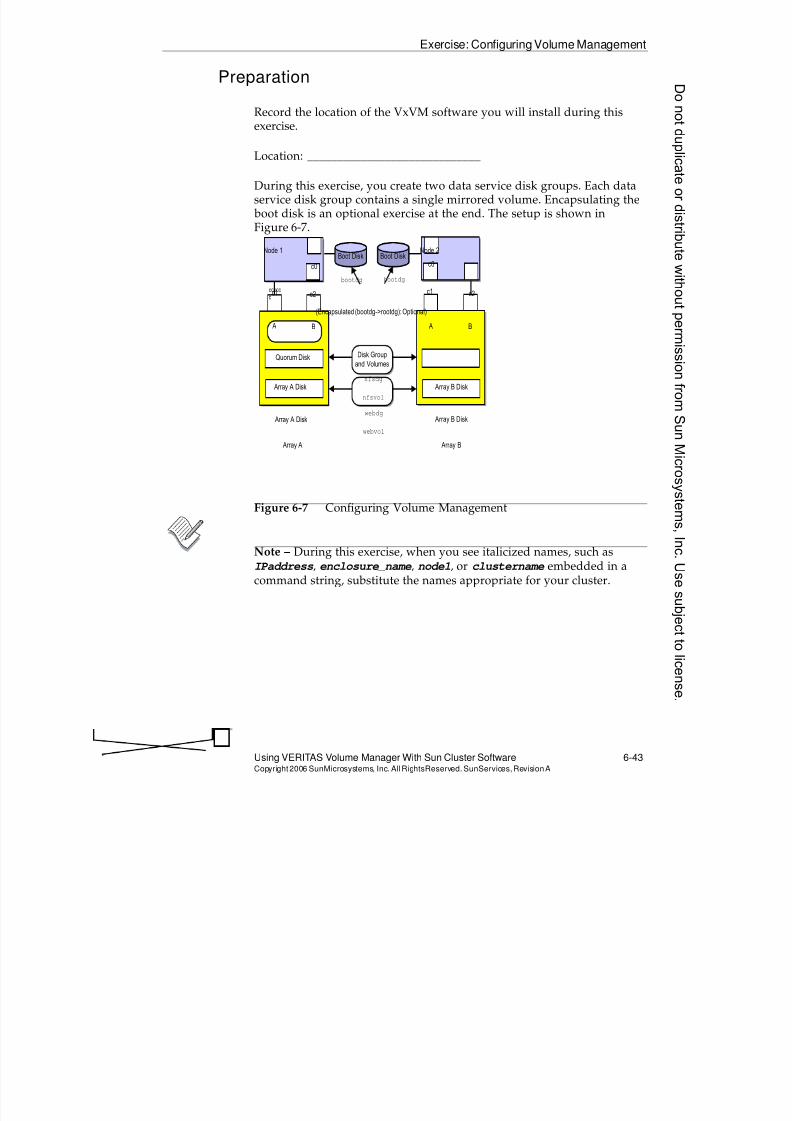
8/4/2019 Sun Cluster 3.2 Administration VC-ES-345
http://slidepdf.com/reader/full/sun-cluster-32-administration-vc-es-345 317/585
Exercise: Configuring Volume Management
Using VERITAS Volume Manager With Sun Cluster Software 6-43Copyright2006 SunMicrosystems, Inc. AllRightsReserved. SunServices,RevisionA
Preparation
Record the location of the VxVM software you will install during thisexercise.
Location: _____________________________
During this exercise, you create two data service disk groups. Each dataservice disk group contains a single mirrored volume. Encapsulating the boot disk is an optional exercise at the end. The setup is shown inFigure 6-7.
Figure 6-7 Configuring Volume Management
Note – During this exercise, when you see italicized names, such asIPaddress, enclosure_name, node1, or clustername embedded in acommand string, substitute the names appropriate for your cluster.
Node 1 Node 2Boot Disk Boot Disk
c2 c1
c0 c0
A B A B
Quorum Disk
Array A Disk
Array A Disk
Disk Group
and Volumes
nfsdg
nfsvol
webdg
webvol
Array A Array B
(Encapsulated (bootdg->rootdg): Optional)
bootdgbootdg
Array B Disk
Array B Disk
ccccc
cc1 c2
8/4/2019 Sun Cluster 3.2 Administration VC-ES-345
http://slidepdf.com/reader/full/sun-cluster-32-administration-vc-es-345 318/585
Exercise: Configuring Volume Management
6-44 Sun™ Cluster 3.2 AdministrationCopyright2006 SunMicrosystems, Inc. AllRights Reserved.SunServices,RevisionA
Task 1 – Selecting Disk Drives
Before proceeding with this exercise, you must have a clear picture of thedisk drives that are used throughout this course. You may have one ormore disks configured as quorum devices (or you may have a quorum
server quorum device). It is perfectly acceptable to use a quorum disk asone of your disk group drives as well. In this exercise, you must identifythe boot disk and two disks in each storage array for use in the twodemonstration disk groups, nfsdg and webdg.
Perform the following step to select a disk drive:
Use the cldev list -v, clq status, and df -k commands toidentify and record the logical addresses of disks for use during thisexercise. Use the address format: c0t2d0.
Quorum disk(s), if any:_________
Node 1 Node 2
Boot disks: _________ _________
Array A Array B
nfsdg disks: _________ _________
webdg disks: _________ _________
Donotduplicate
ordistributewithoutpermissionfrom SunMicrosystems,Inc.Usesubject
tolicense.
8/4/2019 Sun Cluster 3.2 Administration VC-ES-345
http://slidepdf.com/reader/full/sun-cluster-32-administration-vc-es-345 319/585
Exercise: Configuring Volume Management
Using VERITAS Volume Manager With Sun Cluster Software 6-45Copyright2006 SunMicrosystems, Inc. AllRightsReserved. SunServices,RevisionA
Task 2 – Using pkgadd to Install and Initialize VxVMSoftware (on All Storage Nodes )
In this lab, just to save time, you add VxVM packages manually, rather
than usinginstaller
orinstallvm
. This is completely supported.
You need to install VxVM only on nodes connected to the shared storage.If you have a non-storage node (Pair +1 cluster), you do not need to installVxVM on that node.
Perform the following steps on all cluster nodes that are connected toshared storage:
1. Spool and expand the VxVM packages.
# cd vxvm_sw_dir /volume_manager/pkgs
# cp VRTSvlic.tar.gz VRTSvxvm.tar.gz \
VRTSvmman.tar.gz /var/tmp
# cd /var/tmp
# gzcat VRTSvlic.tar.gz | tar xf -
# gzcat VRTSvxvm.tar.gz | tar xf -
# gzcat VRTSvmman.tar.gz | tar xf -
2. Add the new VxVM packages. Answer yes to all questions(including conflicts in directories).
# pkgadd -d /var/tmp VRTSvlic VRTSvxvm VRTSvmman3. Add the VxVM 5.0 patch provided with the courseware. At the time
of writing, there were no patches. Consult your instructor.
# cd location_of_vxvm_patch_for_course
# patchadd patchid
4. Run vxinstall to initialize VxVM:
a. Enter the license information as directed by your instructor
b. AnswerNowhen asked about enclosure-based naming.
c. Answer Nowhen asked about a default disk group.
8/4/2019 Sun Cluster 3.2 Administration VC-ES-345
http://slidepdf.com/reader/full/sun-cluster-32-administration-vc-es-345 320/585
Exercise: Configuring Volume Management
6-46 Sun™ Cluster 3.2 AdministrationCopyright2006 SunMicrosystems, Inc. AllRights Reserved.SunServices,RevisionA
Task 3 – Using clvxvm to Verify the vxioMajor Number
Run the following commands on all nodes on which you have installedVxVM:
# clvxvm initialize
Task 4 – Adding vxio on Any Non-Storage Node onWhich You Have Not Installed VxVM
If you have a non-storage node on which you have not installed VxVM,edit /etc/name_to_major and add a line at the bottom containing thesame vxio major number as used on the storage nodes:
vxio same_major_number_as_other_nodes
Note – Be careful and assure that on the non-storage node the majornumber is not already used by some other device driver on another line inthe file. If it is, you will have to change the vxio major number on allnodes, picking a number higher than currently exists on any node.
Task 5 – Rebooting All Nodes
Reboot all your nodes. In the real production environment, you wouldalways do this one node at a time to maintain the HA of any clusterservices that might already be configured.
Note – Technically the storage nodes would proceed correctly evenwithout a reboot. A non-storage node with the manually created vxio
entry absolutely requires a reboot here. In addition Sun Cluster managerwill fail to operate properly unless you reboot here.
Donotduplicate
ordistributewithoutpermissionfrom SunMicrosystems,Inc.Usesubject
tolicense.
8/4/2019 Sun Cluster 3.2 Administration VC-ES-345
http://slidepdf.com/reader/full/sun-cluster-32-administration-vc-es-345 321/585
Exercise: Configuring Volume Management
Using VERITAS Volume Manager With Sun Cluster Software 6-47Copyright2006 SunMicrosystems, Inc. AllRightsReserved. SunServices,RevisionA
Task 6 – Configuring Demonstration Volumes
Perform the following steps to configure two demonstration disk groups,with each containing a single mirrored volume:
1. On Node 1, create the nfsdg disk group with your previouslyselected logical disk addresses.
# vxdiskadd c# t# d# c# t# d#
Which disk group [<group>,none,list,q,?] (default: none) nfsdg
Create a new group named nfsdg? [y,n,q,?] (default: y) y
Create the disk group as a CDS disk group? [y,n,q,?] (default: y) y
Use default disk names for these disks? [y,n,q,?] (default: y) y
Add disks as spare disks for nfsdg? [y,n,q,?] (default: n) n
Exclude disks from hot-relocation use? [y,n,q,?] (default: n) y
Add site tag to disks? [y,n,q,?] (default: n) n
.
.Continue with operation? [y,n,q,?] (default: y) y
.
Do you want to use the default layout for all disks being initialized?
[y,n,q,?] (default: y) y
Caution – If you are prompted about encapsulating the disk, you shouldreply no. If you are prompted about clearing old disk usage status from aprevious training class, you should reply yes. In your work environment, be careful when answering these questions because you can destroycritical data or cluster node access information.
2. Verify the status of the disk group and the names and ownership ofthe disks in the nfsdg disk group.
# vxdg list
# vxdisk list
3. On Node 1, verify that the new nfsdg disk group is globally linked.
# ls -l /dev/vx/dsk/nfsdg
lrwxrwxrwx 1 root root 12 Dec 6 2006/dev/vx/dsk/nfsdg ->
/global/.devices/node@1/dev/vx/dsk/nfsdg
4. On Node 1, create a 500-Mbyte mirrored volume in the nfsdg diskgroup.
# vxassist -g nfsdg make nfsvol 500m layout=mirror
8/4/2019 Sun Cluster 3.2 Administration VC-ES-345
http://slidepdf.com/reader/full/sun-cluster-32-administration-vc-es-345 322/585
Exercise: Configuring Volume Management
6-48 Sun™ Cluster 3.2 AdministrationCopyright2006 SunMicrosystems, Inc. AllRights Reserved.SunServices,RevisionA
5. On Node 1, create the webdg disk group with your previouslyselected logical disk addresses. Answers in the dialog can be similarto those in Step 1.
# vxdiskadd c# t# d# c# t# d#
Which disk group [<group>,none,list,q,?]
(default: none) webdg
6. On Node 1, create a 500-Mbyte mirrored volume in the webdg diskgroup.
# vxassist -g webdg make webvol 500m layout=mirror
7. Use the vxprint command on both nodes. Notice that Node 2 doesnot see the disk groups created and still imported on Node 1.
8. Issue the following command on the node that currently owns thedisk group:
# newfs /dev/vx/rdsk/webdg/webvol
It should fail with a no such device or address error.
Task 7 – Registering Demonstration Disk Groups
Perform the following steps to register the two new disk groups with theSun Cluster framework software:
1. On Node 1, use the cldg create utility to manually register thenfsdg disk group.
# cldg create -t vxvm -n node1,node2 \-p preferenced=true -p failback=true nfsdg
Note – Put the local node (Node 1) first in the node list.
2. On Node 1, use the clsetup utility to register the webdg disk group.
# clsetup
3. From the main menu, complete the following steps:
a. Select option 5, Device groups and volumes.
b. From the device groups menu, select option 1, Register a VxVMdisk group as a device group.
Donotduplicate
ordistributewithoutpermissionfrom SunMicrosystems,Inc.Usesubject
tolicense.
8/4/2019 Sun Cluster 3.2 Administration VC-ES-345
http://slidepdf.com/reader/full/sun-cluster-32-administration-vc-es-345 323/585
Exercise: Configuring Volume Management
Using VERITAS Volume Manager With Sun Cluster Software 6-49Copyright2006 SunMicrosystems, Inc. AllRightsReserved. SunServices,RevisionA
4. Answer the clsetup questions as follows:
Name of the VxVM disk group you want to register? webdg
Do you want to configure a preferred ordering (yes/no)
[yes]? yes
Are both nodes attached to all disks in this group(yes/no) [yes]? yes
Note – Read the previous question carefully. On a cluster with more thantwo nodes, you will be asked if all nodes are connected to the disks. In aPair +1 configuration, for example, you need to answer no and respondwhen you are asked which nodes are connected to the disks.
Which node is the preferred primary for this device
group? node2
Enable "failback" for this disk device group (yes/no)
[no]? yes
Note – Make sure you specify node2 as the preferred primary node. Youmight see warnings about disks configured by a previous class that stillcontain records about a disk group named webdg. These warnings can besafely ignored.
5. From either node, verify the status of the disk groups.
# cldg status
8/4/2019 Sun Cluster 3.2 Administration VC-ES-345
http://slidepdf.com/reader/full/sun-cluster-32-administration-vc-es-345 324/585
Exercise: Configuring Volume Management
6-50 Sun™ Cluster 3.2 AdministrationCopyright2006 SunMicrosystems, Inc. AllRights Reserved.SunServices,RevisionA
Task 8 – Creating a Global nfsFile System
Perform the following steps on Node 1 to create and mount ademonstration file system on the nfsdg disk group volume:
1. On Node 1, create a file system on nfsvol in the nfsdg disk group.# newfs /dev/vx/rdsk/nfsdg/nfsvol
2. On all nodes, including any non-storage nodes, create a global mountpoint for the new file system.
# mkdir /global/nfs
On all nodes, add a mount entry in the /etc/vfstabfile for the newfile system with the global mount option.
/dev/vx/dsk/nfsdg/nfsvol /dev/vx/rdsk/nfsdg/nfsvol \
/global/nfs ufs 2 yes global
Note – Do not use the line continuation character (\) in the vfstab file.
3. On Node 1, mount the /global/nfs file system.
# mount /global/nfs
4. Verify that the file system is mounted and available on all nodes.
# mount
# ls /global/nfs
lost+found
Task 9 – Creating a Global webFile System
Perform the following steps on Node 2 to create and mount ademonstration file system on the webdg disk group volume:
1. On Node 2, create a file system on webvol in the webdg disk group.
# newfs /dev/vx/rdsk/webdg/webvol
2. On all nodes, create a global mount point for the new file system.
# mkdir /global/web
Donotduplicate
ordistributewithoutpermissionfrom SunMicrosystems,Inc.Usesubject
tolicense.
8/4/2019 Sun Cluster 3.2 Administration VC-ES-345
http://slidepdf.com/reader/full/sun-cluster-32-administration-vc-es-345 325/585
Exercise: Configuring Volume Management
Using VERITAS Volume Manager With Sun Cluster Software 6-51Copyright2006 SunMicrosystems, Inc. AllRightsReserved. SunServices,RevisionA
3. On all nodes, add a mount entry in the /etc/vfstab file for the newfile system with the global mount option.
/dev/vx/dsk/webdg/webvol /dev/vx/rdsk/webdg/webvol \
/global/web ufs 2 yes global
Note – Do not use the line continuation character (\) in the vfstab file.
4. On Node 2, mount the /global/web file system.
# mount /global/web
5. Verify that the file system is mounted and available on all nodes.
# mount
# ls /global/web
lost+found
Task 10 – Testing Global File Systems
Perform the following steps to confirm the general behavior of globallyavailable file systems in the Sun Cluster 3.2 software environment:
1. On Node 2, move into the /global/nfs file system.
# cd /global/nfs
2. On Node 1, try to unmount the /global/nfs file system (umount/global/nfs). You should get an error that the file system is busy.
3. On Node 2, move out of the /global/nfsfile system (cd /) and tryto unmount it again on Node 1.
4. Mount the /global/nfs file system again on Node 1.
5. Try unmounting and mounting /global/nfs from all nodes.
Task 11 – Managing Disk Device Groups
In the Sun Cluster 3.2 software environment, VERITAS disk groups
become cluster device groups when they are registered. In most cases, theyshould not be managed using VERITAS commands. Some administrativetasks are accomplished using a combination of Sun Cluster and VERITAScommands. Common tasks are:
q Adding volumes to a device group
q Removing volumes from a device group
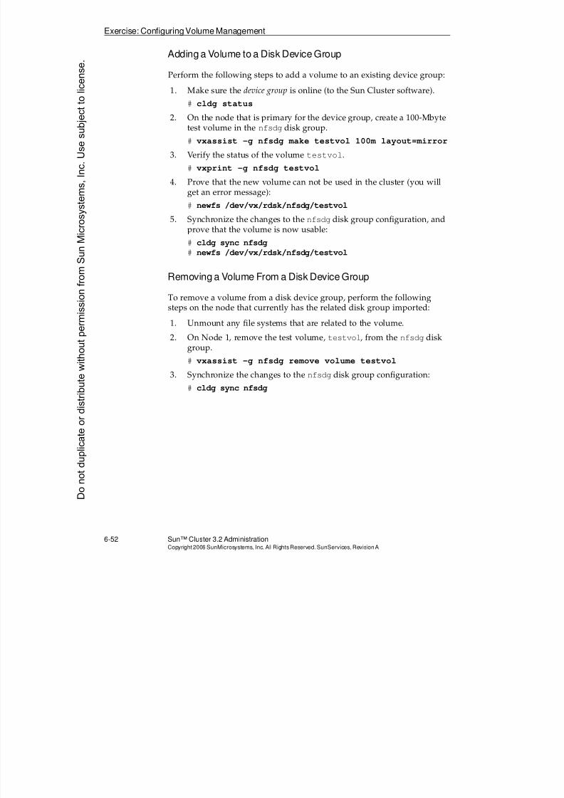
8/4/2019 Sun Cluster 3.2 Administration VC-ES-345
http://slidepdf.com/reader/full/sun-cluster-32-administration-vc-es-345 326/585
Exercise: Configuring Volume Management
6-52 Sun™ Cluster 3.2 AdministrationCopyright2006 SunMicrosystems, Inc. AllRights Reserved.SunServices,RevisionA
Adding a Volume to a Disk Device Group
Perform the following steps to add a volume to an existing device group:
1. Make sure the device group is online (to the Sun Cluster software).
#cldg status
2. On the node that is primary for the device group, create a 100-Mbytetest volume in the nfsdg disk group.
# vxassist -g nfsdg make testvol 100m layout=mirror
3. Verify the status of the volume testvol.
# vxprint -g nfsdg testvol
4. Prove that the new volume can not be used in the cluster (you willget an error message):
# newfs /dev/vx/rdsk/nfsdg/testvol
5. Synchronize the changes to the nfsdg disk group configuration, andprove that the volume is now usable:
# cldg sync nfsdg
# newfs /dev/vx/rdsk/nfsdg/testvol
Removing a Volume From a Disk Device Group
To remove a volume from a disk device group, perform the followingsteps on the node that currently has the related disk group imported:
1. Unmount any file systems that are related to the volume.2. On Node 1, remove the test volume, testvol, from the nfsdg disk
group.
# vxassist -g nfsdg remove volume testvol
3. Synchronize the changes to the nfsdg disk group configuration:
# cldg sync nfsdg
Donotduplicate
ordistributewithoutpermissionfrom SunMicrosystems,Inc.Usesubject
tolicense.
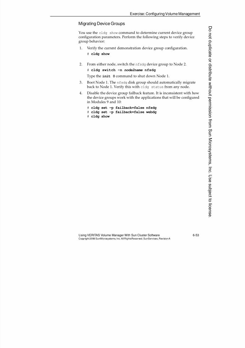
8/4/2019 Sun Cluster 3.2 Administration VC-ES-345
http://slidepdf.com/reader/full/sun-cluster-32-administration-vc-es-345 327/585
Exercise: Configuring Volume Management
Using VERITAS Volume Manager With Sun Cluster Software 6-53Copyright2006 SunMicrosystems, Inc. AllRightsReserved. SunServices,RevisionA
Migrating Device Groups
You use the cldg show command to determine current device groupconfiguration parameters. Perform the following steps to verify devicegroup behavior:
1. Verify the current demonstration device group configuration.
# cldg show
2. From either node, switch the nfsdg device group to Node 2.
# cldg switch -n node2name nfsdg
Type the init 0 command to shut down Node 1.
3. Boot Node 1. The nfsdg disk group should automatically migrate back to Node 1. Verify this with cldg status from any node.
4. Disable the device group failback feature. It is inconsistent with howthe device groups work with the applications that will be configuredin Modules 9 and 10:
# cldg set -p failback=false nfsdg
# cldg set -p failback=false webdg
# cldg show
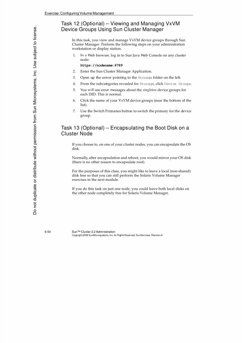
8/4/2019 Sun Cluster 3.2 Administration VC-ES-345
http://slidepdf.com/reader/full/sun-cluster-32-administration-vc-es-345 328/585
Exercise: Configuring Volume Management
6-54 Sun™ Cluster 3.2 AdministrationCopyright2006 SunMicrosystems, Inc. AllRights Reserved.SunServices,RevisionA
Task 12 (Optional) – Viewing and Managing VxVMDevice Groups Using Sun Cluster Manager
In this task, you view and manage VxVM device groups through Sun
Cluster Manager. Perform the following steps on your administrationworkstation or display station.
1. In a Web browser, log in to Sun Java Web Console on any clusternode:
https://nodename:6789
2. Enter the Sun Cluster Manager Application.
3. Open up the arrow pointing to the Storage folder on the left.
4. From the subcategories revealed for Storage, click Device Groups.
5. You will see error messages about the singleton device groups foreach DID. This is normal.
6. Click the name of your VxVM device groups (near the bottom of thelist).
7. Use the Switch Primaries button to switch the primary for the devicegroup.
Task 13 (Optional) – Encapsulating the Boot Disk on aCluster Node
If you choose to, on one of your cluster nodes, you can encapsulate the OSdisk.
Normally, after encapsulation and reboot, you would mirror your OS disk(there is no other reason to encapsulate root).
For the purposes of this class, you might like to leave a local (non-shared)disk free so that you can still perform the Solaris Volume Managerexercises in the next module.
If you do this task on just one node, you could leave both local disks onthe other node completely free for Solaris Volume Manager.
Donotduplicate
ordistributewithoutpermissionfrom SunMicrosystems,Inc.Usesubject
tolicense.
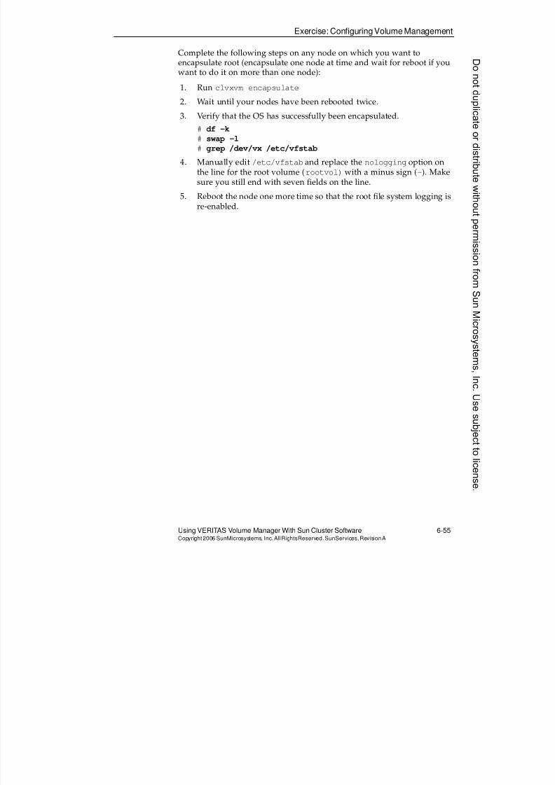
8/4/2019 Sun Cluster 3.2 Administration VC-ES-345
http://slidepdf.com/reader/full/sun-cluster-32-administration-vc-es-345 329/585
Exercise: Configuring Volume Management
Using VERITAS Volume Manager With Sun Cluster Software 6-55Copyright2006 SunMicrosystems, Inc. AllRightsReserved. SunServices,RevisionA
Complete the following steps on any node on which you want toencapsulate root (encapsulate one node at time and wait for reboot if youwant to do it on more than one node):
1. Run clvxvm encapsulate
2. Wait until your nodes have been rebooted twice.3. Verify that the OS has successfully been encapsulated.
# df -k
# swap -l
# grep /dev/vx /etc/vfstab
4. Manually edit /etc/vfstab and replace the nologging option onthe line for the root volume (rootvol) with a minus sign (-). Makesure you still end with seven fields on the line.
5. Reboot the node one more time so that the root file system logging isre-enabled.
8/4/2019 Sun Cluster 3.2 Administration VC-ES-345
http://slidepdf.com/reader/full/sun-cluster-32-administration-vc-es-345 330/585
Exercise Summary
6-56 Sun™ Cluster 3.2 AdministrationCopyright2006 SunMicrosystems, Inc. AllRights Reserved.SunServices,RevisionA
Exercise Summary
?
!
Discussion – Take a few minutes to discuss what experiences, issues, ordiscoveries you had during the lab exercises.
q Experiences
q Interpretations
q Conclusions
q Applications
Donotduplicate
ordistributewithoutpermissionfrom SunMicrosystems,Inc.Usesubject
tolicense.
8/4/2019 Sun Cluster 3.2 Administration VC-ES-345
http://slidepdf.com/reader/full/sun-cluster-32-administration-vc-es-345 331/585
7-1Copyright2006 SunMicrosystems, Inc. AllRights Reserved.SunServices,RevisionA
Module 7
UsingSolarisVolumeManagerWithSunClusterSoftware
Objectives
Upon completion of this module, you should be able to:
q Describe Solaris Volume Manager traditional partitioning and softpartitions
q Differentiate between shared disksets and local disksets
q Describe Solaris Volume Manager multi-owner disksets
q Describe volume database (metadb) management issues and the roleof Solaris Volume Manager mediators
q Configure the Solaris Volume Manager software
q Create the local metadb replicas
q Add disks to shared disksets
q Build Solaris Volume Manager mirrors with soft partitions indisksets
q Use Solaris Volume Manager status commands
q Perform Sun Cluster software-level device group management
q Create global file systems
q Mirror the boot disk with Solaris Volume Manager
q
Describe ZFS and its built-in volume management in contrast totraditional file systems used with a volume manager like Solaris VM
8/4/2019 Sun Cluster 3.2 Administration VC-ES-345
http://slidepdf.com/reader/full/sun-cluster-32-administration-vc-es-345 332/585
Relevance
7-2 Sun™Cluster 3 .2AdministrationCopyright2006 SunMicrosystems, Inc. AllRights Reserved.SunServices,RevisionA
Relevance
?
!
Discussion – The following questions are relevant to understanding thecontent of this module:
q Is it easier to manage Solaris Volume Manager devices with orwithout soft partitions?
q How many different collections of metadbs will you need tomanage?
q What is the advantage of using DID devices as Solaris VolumeManager building blocks in the cluster?
q How are Solaris Volume Manager disksets registered in the cluster?
Donotduplicate
ordistributewithoutpermissionfrom SunMicrosystems,Inc.Usesubject
tolicense.
8/4/2019 Sun Cluster 3.2 Administration VC-ES-345
http://slidepdf.com/reader/full/sun-cluster-32-administration-vc-es-345 333/585
Additional Resources
Using Solaris Volume Manager With Sun Cluster Software 7-3Copyright2006 SunMicrosystems, Inc. AllRightsReserved. SunServices,RevisionA
Additional Resources
Additional resources – The following references provide additional
information on the topics described in this module:q Sun Cluster System Administration Guide for Solaris OS, part number
819-2971.
q Sun Cluster Software Installation Guide for Solaris OS, part number 819-2970.
q Sun Cluster Concepts Guide for Solaris OS, part number 819-2969.
q Solaris Volume Manager Administration Guide, part number 816-4520.

8/4/2019 Sun Cluster 3.2 Administration VC-ES-345
http://slidepdf.com/reader/full/sun-cluster-32-administration-vc-es-345 334/585
Viewing Solaris Volume Manager in the Sun Cluster Software Environment
7-4 Sun™Cluster 3 .2AdministrationCopyright2006 SunMicrosystems, Inc. AllRights Reserved.SunServices,RevisionA
Viewing Solaris Volume Manager in the Sun ClusterSoftware Environment
This module does not intend to replace the full three-day course in disk
management using Solaris Volume Manager. Instead, this module brieflyintroduces the most important concepts of Solaris Volume Manager, andthen focuses on the issues for using Solaris Volume Manager to managedisk space in the cluster environment. Among the topics highlighted inthis module are:
q Using Solaris Volume Manager with and without soft partitions
q Identifying the purpose of Solaris Volume Manager disksets in thecluster
q Managing local diskset database replicas (metadb) and shareddiskset metadb replicas
q Initializing Solaris Volume Manager to build cluster disksets
q Building cluster disksets
q Mirroring with soft partitions in cluster disksets
q Encapsulating and mirroring the cluster boot disk with SolarisVolume Manager
Donotduplicate
ordistributewithoutpermissionfrom SunMicrosystems,Inc.Usesubject
tolicense.
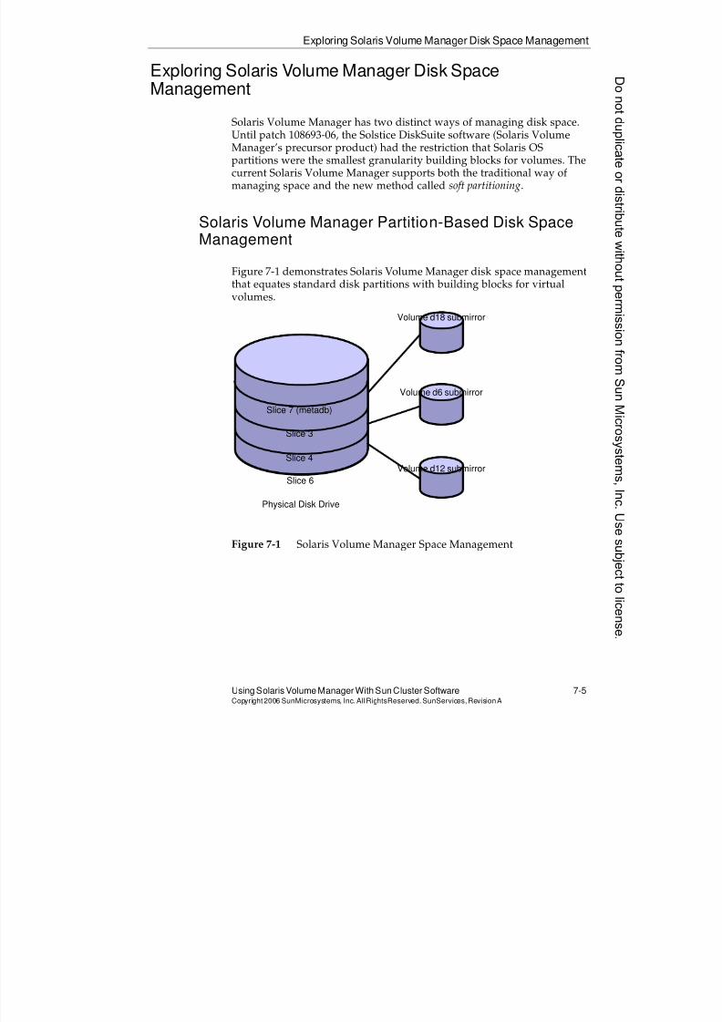
8/4/2019 Sun Cluster 3.2 Administration VC-ES-345
http://slidepdf.com/reader/full/sun-cluster-32-administration-vc-es-345 335/585
Exploring Solaris Volume Manager Disk Space Management
Using Solaris Volume Manager With Sun Cluster Software 7-5Copyright2006 SunMicrosystems, Inc. AllRightsReserved. SunServices,RevisionA
Exploring Solaris Volume Manager Disk SpaceManagement
Solaris Volume Manager has two distinct ways of managing disk space.
Until patch 108693-06, the Solstice DiskSuite software (Solaris VolumeManager’s precursor product) had the restriction that Solaris OSpartitions were the smallest granularity building blocks for volumes. Thecurrent Solaris Volume Manager supports both the traditional way ofmanaging space and the new method called soft partitioning.
Solaris Volume Manager Partition-Based Disk SpaceManagement
Figure 7-1 demonstrates Solaris Volume Manager disk space managementthat equates standard disk partitions with building blocks for virtualvolumes.
Figure 7-1 Solaris Volume Manager Space Management
Physical Disk Drive
Slice 7 (metadb)
Slice 3
Slice 4
Slice 6
Volume d18 submirror
Volume d6 submirror
Volume d12 submirror
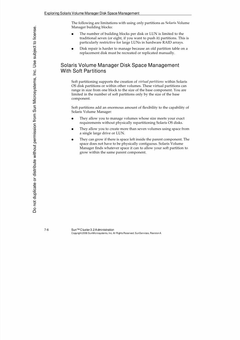
8/4/2019 Sun Cluster 3.2 Administration VC-ES-345
http://slidepdf.com/reader/full/sun-cluster-32-administration-vc-es-345 336/585
Exploring Solaris Volume Manager Disk Space Management
7-6 Sun™Cluster 3 .2AdministrationCopyright2006 SunMicrosystems, Inc. AllRights Reserved.SunServices,RevisionA
The following are limitations with using only partitions as Solaris VolumeManager building blocks:
q The number of building blocks per disk or LUN is limited to thetraditional seven (or eight, if you want to push it) partitions. This isparticularly restrictive for large LUNs in hardware RAID arrays.
q Disk repair is harder to manage because an old partition table on areplacement disk must be recreated or replicated manually.
Solaris Volume Manager Disk Space ManagementWith Soft Partitions
Soft partitioning supports the creation of virtual partitions within SolarisOS disk partitions or within other volumes. These virtual partitions can
range in size from one block to the size of the base component. You arelimited in the number of soft partitions only by the size of the basecomponent.
Soft partitions add an enormous amount of flexibility to the capability ofSolaris Volume Manager:
q They allow you to manage volumes whose size meets your exactrequirements without physically repartitioning Solaris OS disks.
q They allow you to create more than seven volumes using space froma single large drive or LUN.
q They can grow if there is space left inside the parent component. Thespace does not have to be physically contiguous. Solaris VolumeManager finds whatever space it can to allow your soft partition togrow within the same parent component.
Donotduplicate
ordistributewithoutpermissionfrom SunMicrosystems,Inc.Usesubject
tolicense.
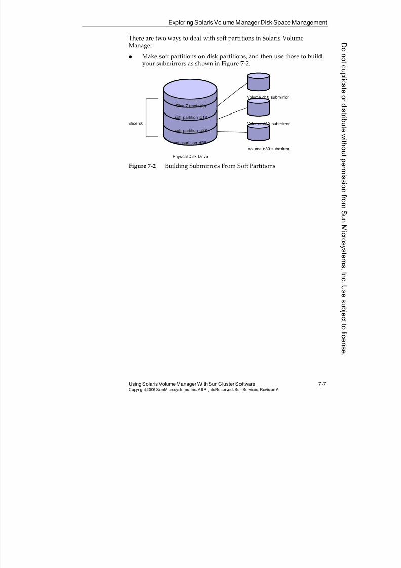
8/4/2019 Sun Cluster 3.2 Administration VC-ES-345
http://slidepdf.com/reader/full/sun-cluster-32-administration-vc-es-345 337/585
Exploring Solaris Volume Manager Disk Space Management
Using Solaris Volume Manager With Sun Cluster Software 7-7Copyright2006 SunMicrosystems, Inc. AllRightsReserved. SunServices,RevisionA
There are two ways to deal with soft partitions in Solaris VolumeManager:
q Make soft partitions on disk partitions, and then use those to buildyour submirrors as shown in Figure 7-2.
Figure 7-2 Building Submirrors From Soft Partitions
Physical Disk Drive
Volume d10 submirror
Volume d20 submirror
Volume d30 submirror
Slice 7 (metadb)
soft partition d18
soft partition d28
soft partition d38
slice s0
8/4/2019 Sun Cluster 3.2 Administration VC-ES-345
http://slidepdf.com/reader/full/sun-cluster-32-administration-vc-es-345 338/585
Exploring Solaris Volume Manager Disk Space Management
7-8 Sun™Cluster 3 .2AdministrationCopyright2006 SunMicrosystems, Inc. AllRights Reserved.SunServices,RevisionA
q Build mirrors using entire partitions, and then use soft partitions tocreate the volumes with the size you want as shown in Figure 7-3.
Figure 7-3 Using Soft Partitions to Create Volumes
All the examples later in this module use the second strategy. Theadvantages of this are the following:
q Volume management is simplified.
q Hot spare management is consistent with how hot spare pools work.
The only disadvantage of this scheme is that you have large mirrordevices even if you are only using a small amount of space. This slowsdown resynching of mirrors.
Physical disk drivePhysical disk drive
Slice 7 (metadb)
slice s0
Slice 7 (metadb)
slice s0
submirrorsubmirror
soft partition
volume
Donotduplicate
ordistributewithoutpermissionfrom SunMicrosystems,Inc.Usesubject
tolicense.
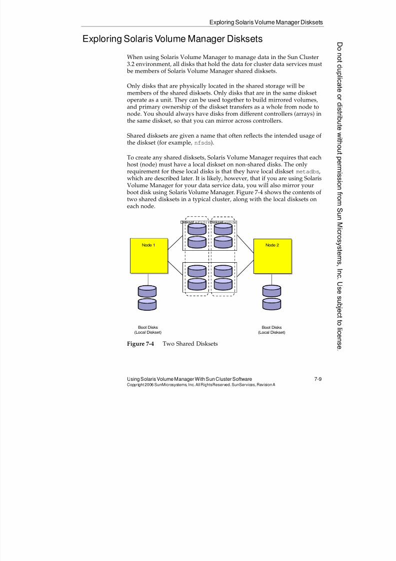
8/4/2019 Sun Cluster 3.2 Administration VC-ES-345
http://slidepdf.com/reader/full/sun-cluster-32-administration-vc-es-345 339/585
Exploring Solaris Volume Manager Disksets
Using Solaris Volume Manager With Sun Cluster Software 7-9Copyright2006 SunMicrosystems, Inc. AllRightsReserved. SunServices,RevisionA
Exploring Solaris Volume Manager Disksets
When using Solaris Volume Manager to manage data in the Sun Cluster3.2 environment, all disks that hold the data for cluster data services must be members of Solaris Volume Manager shared disksets.
Only disks that are physically located in the shared storage will bemembers of the shared disksets. Only disks that are in the same disksetoperate as a unit. They can be used together to build mirrored volumes,and primary ownership of the diskset transfers as a whole from node tonode. You should always have disks from different controllers (arrays) inthe same diskset, so that you can mirror across controllers.
Shared disksets are given a name that often reflects the intended usage ofthe diskset (for example, nfsds).
To create any shared disksets, Solaris Volume Manager requires that eachhost (node) must have a local diskset on non-shared disks. The onlyrequirement for these local disks is that they have local diskset metadbs,which are described later. It is likely, however, that if you are using SolarisVolume Manager for your data service data, you will also mirror your boot disk using Solaris Volume Manager. Figure 7-4 shows the contents oftwo shared disksets in a typical cluster, along with the local disksets oneach node.
Figure 7-4 Two Shared Disksets
Boot Disks
(Local Diskset)
Node 1
Boot Disks
(Local Diskset)
Node 2
Diskset webdsDiskset nfsds
8/4/2019 Sun Cluster 3.2 Administration VC-ES-345
http://slidepdf.com/reader/full/sun-cluster-32-administration-vc-es-345 340/585
Solaris Volume Manager Multi-Owner Disksets (for Oracle RAC)
7-10 Sun™ Cluster 3.2 AdministrationCopyright2006 SunMicrosystems, Inc. AllRights Reserved.SunServices,RevisionA
Solaris Volume Manager Multi-Owner Disksets (for OracleRAC)
Solaris Volume Manager has a multi-owner diskset feature that is
analogous to the VERITAS Cluster Volume Manager (CVM) feature. Thatis, a multi-owner diskset allows more than one node to physically accessthe storage, simultaneously.
In the current implementation, multi-owner disksets are only for use withOracle RAC software. In fact, you cannot create a multi-owner disksetuntil you have enabled a layer of software underlying Oracle RAC knownas the RAC framework. This is described in more detail, and you will geta chance to work with it, if you choose, in one of the optional exercises inModule 11.
Managing multi-owner disksets is identical to managing other disksets,except that you use a -M option when you create the diskset.
Donotduplicate
ordistributewithoutpermissionfrom SunMicrosystems,Inc.Usesubject
tolicense.
8/4/2019 Sun Cluster 3.2 Administration VC-ES-345
http://slidepdf.com/reader/full/sun-cluster-32-administration-vc-es-345 341/585
Using Solaris Volume Manager DatabaseReplicas (metadbReplicas)
Using Solaris Volume Manager With Sun Cluster Software 7-11Copyright2006 SunMicrosystems, Inc. AllRightsReserved. SunServices,RevisionA
Using Solaris Volume Manager Database Replicas(metadbReplicas)
Solaris Volume Manager requires that certain partitions serve as volume
database replicas, storing the Solaris Volume Manager configuration andstate information in a raw format (non-file system). These are normallysmall, dedicated Solaris OS partitions. In the local disksets, Solaris VolumeManager allows the creation of metadbs on a large partition and then theuse of the same partition as a component in a volume. The reasons whyyou would never want to do this on the boot disks are described later inthis module.
There are separate sets of metadb replicas for the local disksets and foreach shared diskset. For example, in Figure 7-4 on page 7-9 (which showstwo nodes and two shared disksets), there are four distinct collections of
metadb replicas.
You can put several copies of the metadb on the same partition. You mightdo this to balance the numbers of metadb replicas across disks orpartitions, for reasons described in the following subsections.
Local Replica Management
When managing local replicas:
q You must add local replicas manually.
q You can put local replicas on any dedicated partitions on the localdisks. You might prefer to use slice 7 (s7) as a convention becausethe shared diskset replicas have to be on that partition.
q You must spread local replicas evenly across disks and controllers.
q If you have less than three local replicas, Solaris Volume Managerlogs warnings. You can put more than one copy in the same partitionto satisfy this requirement. For example, with two local disks, set upa dedicated partition on each disk and put three copies on each disk.
8/4/2019 Sun Cluster 3.2 Administration VC-ES-345
http://slidepdf.com/reader/full/sun-cluster-32-administration-vc-es-345 342/585
Using Solaris Volume Manager Database Replicas (metadbReplicas)
7-12 Sun™ Cluster 3.2 AdministrationCopyright2006 SunMicrosystems, Inc. AllRights Reserved.SunServices,RevisionA
Local Replica Mathematics
The math for local replicas is as follows:
q If fewer than 50 percent of the defined metadb replicas are available,
Solaris Volume Manager ceases to operate.q If fewer than or equal to 50 percent of the defined metadb replicas
are available at boot time, you cannot boot the node. However, youcan boot to single-user mode, and just use the metadb command todelete ones that are not available.
Shared Diskset Replica Management
Consider the following issues when managing shared diskset replicas:
q There are separate metadb replicas for each diskset.
q They are automatically added to disks as you add disks to disk sets.They will be, and must remain, on slice 7.
q You must use the metadb command to remove and add replicas ifyou replace a disk containing replicas.
Shared Diskset Replica Quorum Mathematics
The math for shared diskset replica quorums is as follows:
q If fewer than 50 percent of the defined replicas for a diskset areavailable, the diskset ceases to operate.
q If exactly 50 percent of the defined replicas for a diskset areavailable, the diskset still operates, but it cannot be taken or switchedover.
Shared Diskset Mediators
When you have nodes connected to exactly two storage arrays, theimplication of the replica mathematics described in the previous section isthat if one storage array fails, your diskset can keep operating, but cannottransfer primary control from node to node.
Donotduplicate
ordistributewithoutpermissionfrom SunMicrosystems,Inc.Usesubject
tolicense.
8/4/2019 Sun Cluster 3.2 Administration VC-ES-345
http://slidepdf.com/reader/full/sun-cluster-32-administration-vc-es-345 343/585
Using Solaris Volume Manager DatabaseReplicas (metadbReplicas)
Using Solaris Volume Manager With Sun Cluster Software 7-13Copyright2006 SunMicrosystems, Inc. AllRightsReserved. SunServices,RevisionA
This is unacceptable in the Sun Cluster environment, because it can take awhile to fix a broken array or controller, and you still want to be able togracefully survive a node failure during that period.
The Sun Cluster 3.2 software environment includes special add-ons to
Solaris Volume Manager called mediators. Mediators allow you to identifythe nodes themselves as tie-breaking votes in the case of failure of exactly 50percent of the metadb replicas of a shared diskset. The mediator data isstored in the memory of a running Solaris OS process on each node. If youlose an array, the node mediators will change to golden status, indicatingthey count as two extra votes for the shared diskset quorum mathematics(one from each node). This allows you to maintain normal disksetoperations with exactly 50 percent of the metadb replicas surviving. Youcan also lose a node at this point (you would still have one tie-breaking,golden mediator).
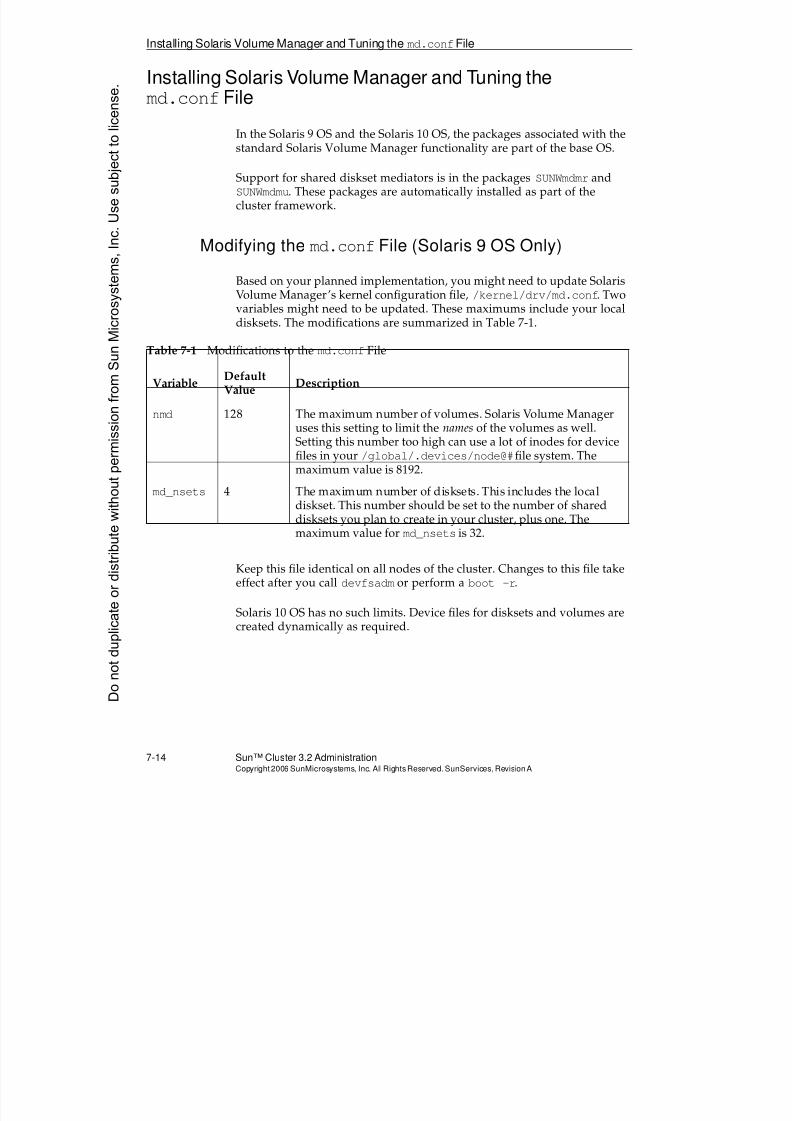
8/4/2019 Sun Cluster 3.2 Administration VC-ES-345
http://slidepdf.com/reader/full/sun-cluster-32-administration-vc-es-345 344/585
Installing Solaris Volume Manager and Tuning themd.confFile
7-14 Sun™ Cluster 3.2 AdministrationCopyright2006 SunMicrosystems, Inc. AllRights Reserved.SunServices,RevisionA
Installing Solaris Volume Manager and Tuning themd.confFile
In the Solaris 9 OS and the Solaris 10 OS, the packages associated with the
standard Solaris Volume Manager functionality are part of the base OS.
Support for shared diskset mediators is in the packages SUNWmdmr andSUNWmdmu. These packages are automatically installed as part of thecluster framework.
Modifying the md.confFile (Solaris 9 OS Only)
Based on your planned implementation, you might need to update SolarisVolume Manager’s kernel configuration file, /kernel/drv/md.conf. Twovariables might need to be updated. These maximums include your localdisksets. The modifications are summarized in Table 7-1.
Keep this file identical on all nodes of the cluster. Changes to this file takeeffect after you call devfsadm or perform a boot -r.
Solaris 10 OS has no such limits. Device files for disksets and volumes arecreated dynamically as required.
Table 7-1 Modifications to the md.conf File
Variable DefaultValue Description
nmd 128 The maximum number of volumes. Solaris Volume Manageruses this setting to limit the names of the volumes as well.Setting this number too high can use a lot of inodes for device
files in your /global/.devices/node@#file system. Themaximum value is 8192.
md_nsets 4 The maximum number of disksets. This includes the localdiskset. This number should be set to the number of shareddisksets you plan to create in your cluster, plus one. Themaximum value for md_nsets is 32.
Donotduplicate
ordistributewithoutpermissionfrom SunMicrosystems,Inc.Usesubject
tolicense.
8/4/2019 Sun Cluster 3.2 Administration VC-ES-345
http://slidepdf.com/reader/full/sun-cluster-32-administration-vc-es-345 345/585
Initializing the Local metadbReplicas on Boot Disk and Mirror
Using Solaris Volume Manager With Sun Cluster Software 7-15Copyright2006 SunMicrosystems, Inc. AllRightsReserved. SunServices,RevisionA
Initializing the Local metadbReplicas on Boot Disk andMirror
Solaris Volume Manager management cannot be performed until you
initialize the local metadb replicas on each node.
These instructions assume that you have a small partition to use for themetadb replicas on your boot disk. In this example, the partition is s7.
The instructions presented in the following section assume that you areeventually going to mirror your boot drive. As such, they instruct you topartition the eventual boot mirror identically to the boot drive and to addlocal metadb replicas there as well.
Make sure you initialize local metadb replicas correctly and separately on
each node.
Using DIDs Compared to Using Traditional c#t#d#
In the Sun Cluster environment, you can add any metadb or partitioncomponent using either its cluster DID (/dev/did/rdsk/d#s#) or byusing the traditional c#t#d#.
Use the DID naming for all shared disksets. Without it you are restricted
to having identical controller numbers on each node. You might assumethis will always be true, then be surprised when you add a new node orrepair a node.
Use the traditional c#t#d# naming scheme for local metadb replicas anddevices. This makes recovery easier in the case that you need to accessthese structures when booted in non-clustered mode. Omit the /dev/rdskto abbreviate traditional names in all of the Solaris Volume Managercommands.
Adding the Local metadbReplicas to the Boot Disk
Use the metadb -a command to add local metadb replicas. As you addthe first ones, you must use the -f (force) option. The following examplecreates three copies:
# metadb -a -f -c 3 c0t0d0s7
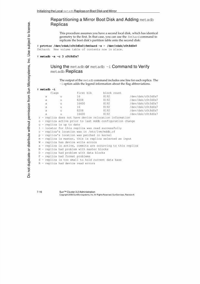
8/4/2019 Sun Cluster 3.2 Administration VC-ES-345
http://slidepdf.com/reader/full/sun-cluster-32-administration-vc-es-345 346/585
Initializing the Local metadbReplicas on Boot Disk and Mirror
7-16 Sun™ Cluster 3.2 AdministrationCopyright2006 SunMicrosystems, Inc. AllRights Reserved.SunServices,RevisionA
Repartitioning a Mirror Boot Disk and Adding metadbReplicas
This procedure assumes you have a second local disk, which has identical
geometry to the first. In that case, you can use thefmthard
command toreplicate the boot disk’s partition table onto the second disk:
# prtvtoc /dev/rdsk/c0t0d0s0|fmthard -s - /dev/rdsk/c0t8d0s0
fmthard: New volume table of contents now in place.
# metadb -a -c 3 c0t8d0s7
Using the metadb or metadb -iCommand to VerifymetadbReplicas
The output of the metadb command includes one line for each replica. The-i option adds the legend information about the flag abbreviations.
# metadb -i
flags first blk block count
a u 16 8192 /dev/dsk/c0t0d0s7
a u 8208 8192 /dev/dsk/c0t0d0s7
a u 16400 8192 /dev/dsk/c0t0d0s7
a u 16 8192 /dev/dsk/c0t8d0s7
a u 8208 8192 /dev/dsk/c0t8d0s7
a u 16400 8192 /dev/dsk/c0t8d0s7r - replica does not have device relocation information
o - replica active prior to last mddb configuration change
u - replica is up to date
l - locator for this replica was read successfully
c - replica's location was in /etc/lvm/mddb.cf
p - replica's location was patched in kernel
m - replica is master, this is replica selected as input
W - replica has device write errors
a - replica is active, commits are occurring to this replica
M - replica had problem with master blocks
D - replica had problem with data blocksF - replica had format problems
S - replica is too small to hold current data base
R - replica had device read errors
Donotduplicate
ordistributewithoutpermissionfrom SunMicrosystems,Inc.Usesubject
tolicense.
8/4/2019 Sun Cluster 3.2 Administration VC-ES-345
http://slidepdf.com/reader/full/sun-cluster-32-administration-vc-es-345 347/585
Creating Shared Disksets and Mediators
Using Solaris Volume Manager With Sun Cluster Software 7-17Copyright2006 SunMicrosystems, Inc. AllRightsReserved. SunServices,RevisionA
Creating Shared Disksets and Mediators
Use the metaset command to create new empty disksets and to add diskdrives into the diskset. You must use the -a -h options of the metasetcommand first to create an empty diskset. Then you can add disks. Thefirst host listed as you create a new diskset is the first one to be the ownerof the diskset. You can add mediators with the -a -m options.
All the examples shown in this module of diskset operations use the DIDnames for disks instead of the c#t#d# names. You might need to run thecldev list command often to map between the two.
# cldev list -v c1t3d0
DID Device Full Device Path
---------- ----------------
d17 vincent:/dev/rdsk/c1t3d0
d17 theo:/dev/rdsk/c1t3d0# cldev list -v d17
DID Device Full Device Path
---------- ----------------
d17 vincent:/dev/rdsk/c1t3d0
d17 theo:/dev/rdsk/c1t3d0
# metaset -s nfsds -a -h vincent theo
# metaset -s nfsds -a -m vincent theo
# metaset -s nfsds -a /dev/did/rdsk/d9 /dev/did/rdsk/d17
# metaset
Set name = nfsds, Set number = 1
Host Owner
vincent Yes
theo
Mediator Host(s) Aliases
vincent
theo
Drive Dbase
d9 Yes
d17 Yes
8/4/2019 Sun Cluster 3.2 Administration VC-ES-345
http://slidepdf.com/reader/full/sun-cluster-32-administration-vc-es-345 348/585
Creating Shared Disksets and Mediators
7-18 Sun™ Cluster 3.2 AdministrationCopyright2006 SunMicrosystems, Inc. AllRights Reserved.SunServices,RevisionA
# metadb -s nfsds
flags first blk block count
a u r 16 8192 /dev/did/dsk/d9s7
a u r 16 8192 /dev/did/dsk/d17s7
# medstat -s nfsds
Mediator Status Golden
vincent Ok No
theo Ok No
Mediators become golden if exactly 50 percent of the metadb replicas fail.
Automatic Repartitioning and metadbPlacement onShared Disksets
When a disk is added to a diskset, it is automatically repartitioned asfollows:
q A small portion of the drive (starting at cylinder 0) is mapped to slice7 or slice 6 to be used for state database replicas (at least 4 Mbytes insize).
Note – Sun Cluster 3.2 is the first Sun Cluster version to fully supportdisks with Extensible Firmware Interface (EFI) labels, which are requiredfor disks of size greater than 1 Terabyte (Tbyte). These disks have no slice7. Solaris Volume Manager automatically detects an EFI disk, and usesslice 6 for the metadb partition.
q One metadb is added to slice 7 or 6 as appropriate.
q Slice 7 or 6 is marked with the flag bits 01 (this shows up as wuwhenyou view the disk from the format command – writable butunmountable).
q The rest of the drive is mapped to slice 0 (on a standard VTOC disk,even slice 2 is deleted).
The drive is not repartitioned if the disk already has no slice 2 and slice 7already has the following characteristics:
q It starts at cylinder 0.
q It has at least 4 Mbytes (large enough to hold a state database).
q The flag bits are already 01 (wu in format command).Donotduplicate
ordistributewithoutpermissionfrom SunMicrosystems,Inc.Usesubject
tolicense.
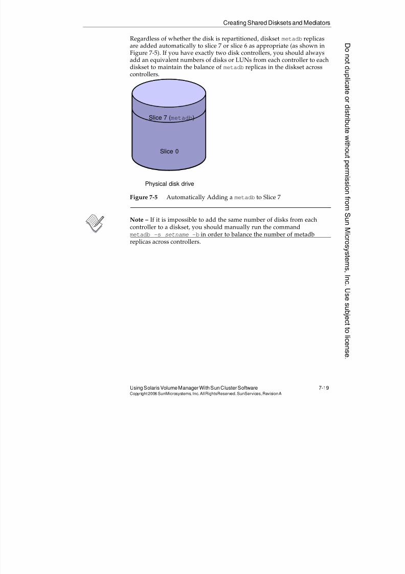
8/4/2019 Sun Cluster 3.2 Administration VC-ES-345
http://slidepdf.com/reader/full/sun-cluster-32-administration-vc-es-345 349/585
Creating Shared Disksets and Mediators
Using Solaris Volume Manager With Sun Cluster Software 7-19Copyright2006 SunMicrosystems, Inc. AllRightsReserved. SunServices,RevisionA
Regardless of whether the disk is repartitioned, diskset metadb replicasare added automatically to slice 7 or slice 6 as appropriate (as shown inFigure 7-5). If you have exactly two disk controllers, you should alwaysadd an equivalent numbers of disks or LUNs from each controller to eachdiskset to maintain the balance of metadb replicas in the diskset across
controllers.
Figure 7-5 Automatically Adding a metadb to Slice 7
Note – If it is impossible to add the same number of disks from eachcontroller to a diskset, you should manually run the command
metadb -s setname -b in order to balance the number of metadbreplicas across controllers.
Physical disk drive
Slice 7 (metadb)
Slice 0
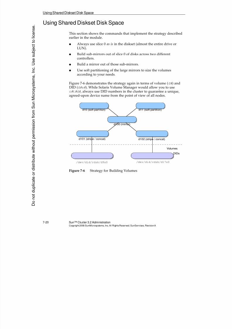
8/4/2019 Sun Cluster 3.2 Administration VC-ES-345
http://slidepdf.com/reader/full/sun-cluster-32-administration-vc-es-345 350/585
Using Shared Diskset Disk Space
7-20 Sun™ Cluster 3.2 AdministrationCopyright2006 SunMicrosystems, Inc. AllRights Reserved.SunServices,RevisionA
Using Shared Diskset Disk Space
This section shows the commands that implement the strategy describedearlier in the module.
q Always use slice 0 as is in the diskset (almost the entire drive orLUN).
q Build sub-mirrors out of slice 0 of disks across two differentcontrollers.
q Build a mirror out of those sub-mirrors.
q Use soft partitioning of the large mirrors to size the volumesaccording to your needs.
Figure 7-6 demonstrates the strategy again in terms of volume (d#) and
DID (d#s#). While Solaris Volume Manager would allow you to usec#t#d#, always use DID numbers in the cluster to guarantee a unique,agreed-upon device name from the point of view of all nodes.
Figure 7-6 Strategy for Building Volumes
d10 (soft partition) d11 (soft partition)
d101 (stripe / concat) d102 (stripe / concat)
/dev/did/rdsk/d9s0 /dev/did/rdsk/d17s0
d100 (mirror)
Volumes
DIDs
Donotduplicate
ordistributewithoutpermissionfrom SunMicrosystems,Inc.Usesubject
tolicense.
8/4/2019 Sun Cluster 3.2 Administration VC-ES-345
http://slidepdf.com/reader/full/sun-cluster-32-administration-vc-es-345 351/585
Building Volumes in Shared Disksets With Soft Partitions of Mirrors
Using Solaris Volume Manager With Sun Cluster Software 7-21Copyright2006 SunMicrosystems, Inc. AllRightsReserved. SunServices,RevisionA
Building Volumes in Shared Disksets With Soft Partitionsof Mirrors
The following are two ways to indicate which diskset you are referring to
for each metainit command:q Use -s disksetname with the command
q Use disksetname/d# for volume operands in the command
This module uses the former model for all the examples.
The following is an example of the commands that are used to build theconfiguration described in Figure 7-6 on page 7-20:
# metainit -s nfsds d101 1 1 /dev/did/rdsk/d9s0
nfsds/d101: Concat/Stripe is setup# metainit -s nfsds d102 1 1 /dev/did/rdsk/d17s0
nfsds/d102: Concat/Stripe is setup
# metainit -s nfsds d100 -m d101
nfsds/d100: Mirror is setup
# metattach -s nfsds d100 d102
nfsds/d100: submirror nfsds/d102 is attached
# metainit -s nfsds d10 -p d100 200m
d10: Soft Partition is setup
# metainit -s nfsds d11 -p d100 200m
d11: Soft Partition is setup
The following commands show how a soft partition can be grown if thereis space in the parent volume, even non-contiguous space. You will see inthe output of metastat on the next page how both soft partitions containnoncontiguous space, because of the order in which they are created andgrown.
# metattach -s nfsds d10 400m
nfsds/d10: Soft Partition has been grown
/ metattach -s nfsds d11 400m
nfsds/d11: Soft Partition has been grown
Note – The volumes are being increased by 400 Mbytes, to a total size of600 Mbytes.
8/4/2019 Sun Cluster 3.2 Administration VC-ES-345
http://slidepdf.com/reader/full/sun-cluster-32-administration-vc-es-345 352/585
Using Solaris Volume Manager Status Commands
7-22 Sun™ Cluster 3.2 AdministrationCopyright2006 SunMicrosystems, Inc. AllRights Reserved.SunServices,RevisionA
Using Solaris Volume Manager Status Commands
No commands display information about volumes or metadb replicas inmultiple disksets at the same time. If you do not specify a diskset name(with -s), you get output only about the local diskset on the node onwhich you entered the command.
Checking Volume Status
The following metastat command output is for the mirrored volume andsoft partitions built in the previous example:
# metastat -s nfsds
nfsds/d11: Soft Partition
Device: nfsds/d100
State: Okay
Size: 1228800 blocks (600 MB)
Extent Start Block Block count
0 409664 409600
1 1638528 819200
nfsds/d100: Mirror
Submirror 0: nfsds/d101
State: Okay
Submirror 1: nfsds/d102
State: Resyncing
Resync in progress: 0 % done
Pass: 1
Read option: roundrobin (default)
Write option: parallel (default)
Size: 71118513 blocks (33 GB)
nfsds/d101: Submirror of nfsds/d100
State: Okay
Size: 71118513 blocks (33 GB)
Stripe 0:
Device Start Block Dbase State Reloc Hot Spared9s0 0 No Okay No
nfsds/d102: Submirror of nfsds/d100
State: Resyncing
Size: 71118513 blocks (33 GB)
Stripe 0:Donotduplicate
ordistributewithoutpermissionfrom SunMicrosystems,Inc.Usesubject
tolicense.
8/4/2019 Sun Cluster 3.2 Administration VC-ES-345
http://slidepdf.com/reader/full/sun-cluster-32-administration-vc-es-345 353/585
UsingSolaris Volume Manager Status Commands
Using Solaris Volume Manager With Sun Cluster Software 7-23Copyright2006 SunMicrosystems, Inc. AllRightsReserved. SunServices,RevisionA
Device Start Block Dbase State Reloc Hot Spare
d17s0 0 No Okay No
nfsds/d10: Soft Partition
Device: nfsds/d100
State: Okay
Size: 1228800 blocks (600 MB)
Extent Start Block Block count
0 32 409600
1 819296 819200
Device Relocation Information:
Device Reloc Device ID
d17 No -
d9 No -
8/4/2019 Sun Cluster 3.2 Administration VC-ES-345
http://slidepdf.com/reader/full/sun-cluster-32-administration-vc-es-345 354/585
Managing Solaris Volume Manager Disk9]H and Sun Cluster Device Groups
7-24 Sun™ Cluster 3.2 AdministrationCopyright2006 SunMicrosystems, Inc. AllRights Reserved.SunServices,RevisionA
Managing Solaris Volume Manager Disk9]H and SunCluster Device Groups
When Solaris Volume Manager is used in the cluster environment, the
commands are tightly integrated into the cluster. Creation of a shareddiskset automatically registers that diskset as a cluster-managed devicegroup:
# cldg status
Cluster Device Groups ===
--- Device Group Status ---
Device Group Name Primary Secondary Status
----------------- ------- --------- ------
nfsds vincent theo Online
# cldg show nfsds
Device Groups ===
Device Group Name: nfsds
Type: SVM
failback: false
Node List: vincent, theo
preferenced: true
numsecondaries: 1
diskset name: nfsds
Addition or removal of a directly connected node to the diskset usingmetaset -s nfsds -a -h newnode automatically updates the clusterto add or remove the node from its list. There is no need to use clustercommands to resynchronize the device group if volumes are added anddeleted.
In the Sun Cluster environment, use only the cldg switch command(rather than the metaset -[rt] commands) to change physicalownership of the diskset. As demonstrated in this example, if a mirror isin the middle of synching, this forces a switch anyway and restarts thesynch of the mirror all over again.
# cldg switch -n theo nfsds
Donotduplicate
ordistributewithoutpermissionfrom SunMicrosystems,Inc.Usesubject
tolicense.
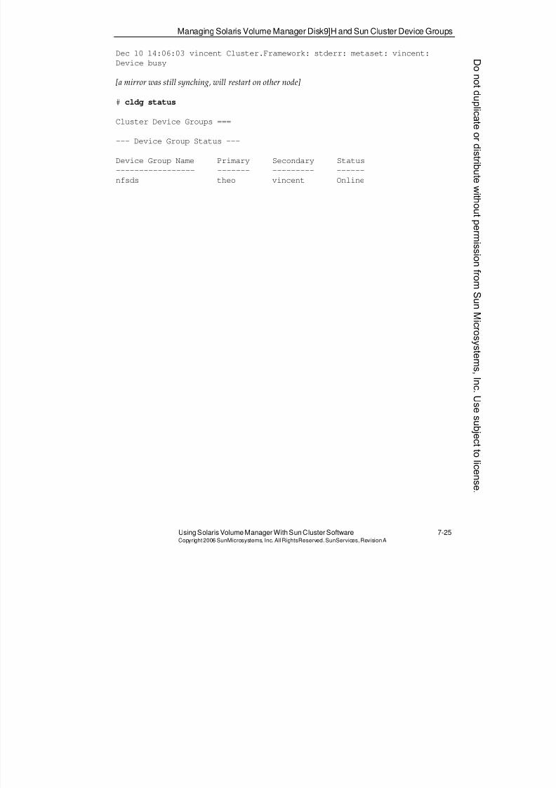
8/4/2019 Sun Cluster 3.2 Administration VC-ES-345
http://slidepdf.com/reader/full/sun-cluster-32-administration-vc-es-345 355/585
Managing Solaris Volume Manager Disk9]H and Sun Cluster Device Groups
Using Solaris Volume Manager With Sun Cluster Software 7-25Copyright2006 SunMicrosystems, Inc. AllRightsReserved. SunServices,RevisionA
Dec 10 14:06:03 vincent Cluster.Framework: stderr: metaset: vincent:
Device busy
[a mirror was still synching, will restart on other node]
# cldg status
Cluster Device Groups ===
--- Device Group Status ---
Device Group Name Primary Secondary Status
----------------- ------- --------- ------
nfsds theo vincent Online
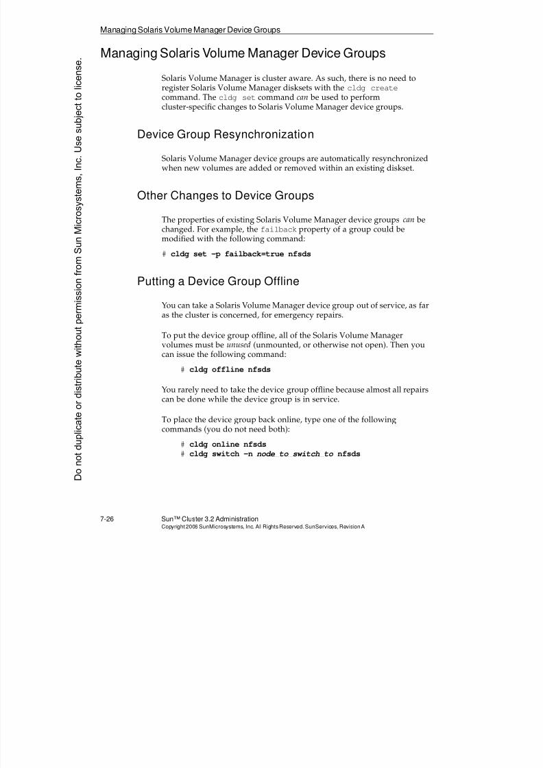
8/4/2019 Sun Cluster 3.2 Administration VC-ES-345
http://slidepdf.com/reader/full/sun-cluster-32-administration-vc-es-345 356/585
Managing Solaris Volume Manager Device Groups
7-26 Sun™ Cluster 3.2 AdministrationCopyright2006 SunMicrosystems, Inc. AllRights Reserved.SunServices,RevisionA
Managing Solaris Volume Manager Device Groups
Solaris Volume Manager is cluster aware. As such, there is no need toregister Solaris Volume Manager disksets with the cldg create
command. The cldg set command can be used to performcluster-specific changes to Solaris Volume Manager device groups.
Device Group Resynchronization
Solaris Volume Manager device groups are automatically resynchronizedwhen new volumes are added or removed within an existing diskset.
Other Changes to Device Groups
The properties of existing Solaris Volume Manager device groups can bechanged. For example, the failback property of a group could bemodified with the following command:
# cldg set -p failback=true nfsds
Putting a Device Group Offline
You can take a Solaris Volume Manager device group out of service, as faras the cluster is concerned, for emergency repairs.
To put the device group offline, all of the Solaris Volume Managervolumes must be unused (unmounted, or otherwise not open). Then youcan issue the following command:
# cldg offline nfsds
You rarely need to take the device group offline because almost all repairscan be done while the device group is in service.
To place the device group back online, type one of the followingcommands (you do not need both):
# cldg online nfsds
# cldg switch -n node_to_switch_to nfsds
Donotduplicate
ordistributewithoutpermissionfrom SunMicrosystems,Inc.Usesubject
tolicense.
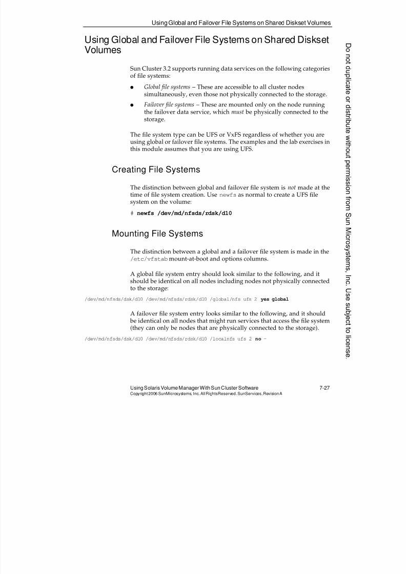
8/4/2019 Sun Cluster 3.2 Administration VC-ES-345
http://slidepdf.com/reader/full/sun-cluster-32-administration-vc-es-345 357/585
UsingGlobal and Failover File Systems on Shared Diskset Volumes
Using Solaris Volume Manager With Sun Cluster Software 7-27Copyright2006 SunMicrosystems, Inc. AllRightsReserved. SunServices,RevisionA
Using Global and Failover File Systems on Shared DisksetVolumes
Sun Cluster 3.2 supports running data services on the following categories
of file systems:q Global file systems – These are accessible to all cluster nodes
simultaneously, even those not physically connected to the storage.
q Failover file systems – These are mounted only on the node runningthe failover data service, which must be physically connected to thestorage.
The file system type can be UFS or VxFS regardless of whether you areusing global or failover file systems. The examples and the lab exercises inthis module assumes that you are using UFS.
Creating File Systems
The distinction between global and failover file system is not made at thetime of file system creation. Use newfs as normal to create a UFS filesystem on the volume:
# newfs /dev/md/nfsds/rdsk/d10
Mounting File Systems
The distinction between a global and a failover file system is made in the/etc/vfstabmount-at-boot and options columns.
A global file system entry should look similar to the following, and itshould be identical on all nodes including nodes not physically connectedto the storage:
/dev/md/nfsds/dsk/d10 /dev/md/nfsds/rdsk/d10 /global/nfs ufs 2 yes global
A failover file system entry looks similar to the following, and it should be identical on all nodes that might run services that access the file system(they can only be nodes that are physically connected to the storage).
/dev/md/nfsds/dsk/d10 /dev/md/nfsds/rdsk/d10 /localnfs ufs 2 no -
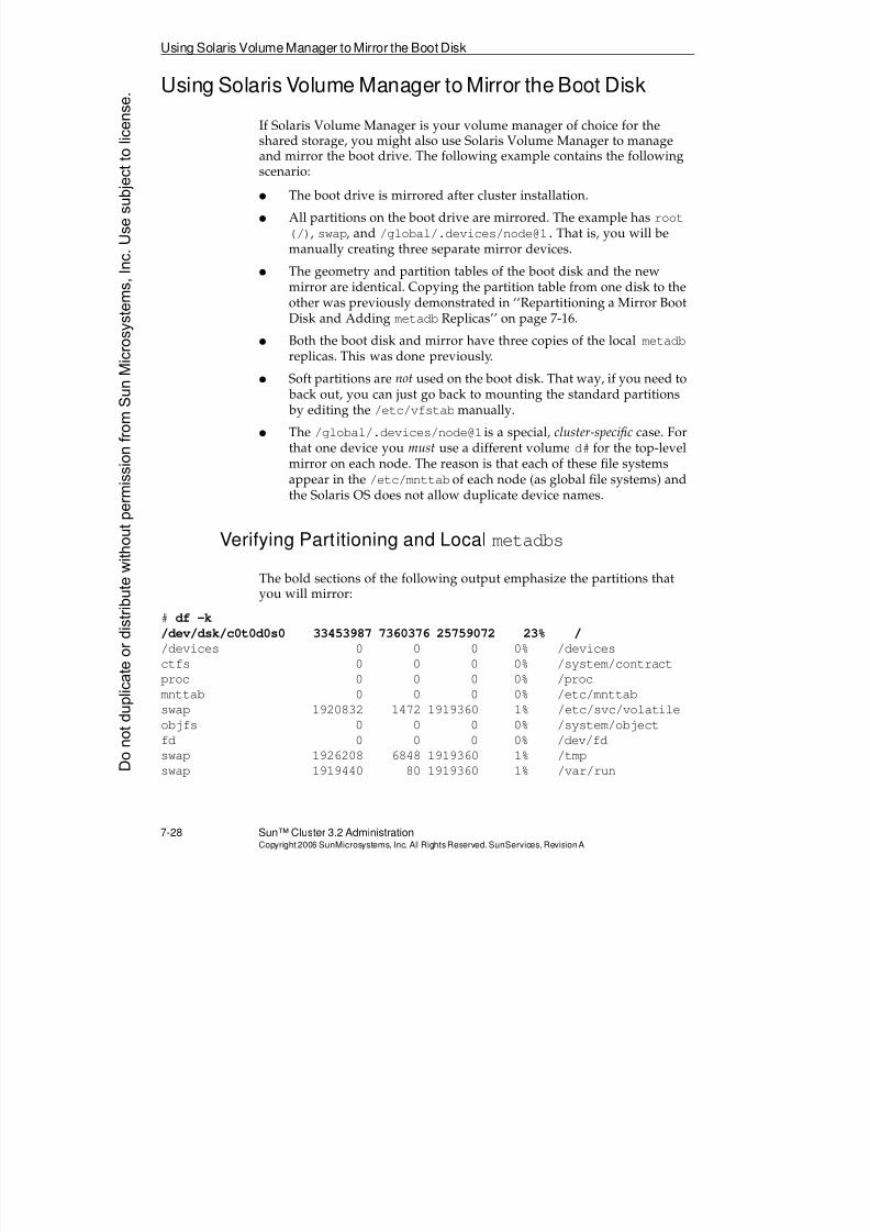
8/4/2019 Sun Cluster 3.2 Administration VC-ES-345
http://slidepdf.com/reader/full/sun-cluster-32-administration-vc-es-345 358/585
Using Solaris Volume Manager to Mirror the Boot Disk
7-28 Sun™ Cluster 3.2 AdministrationCopyright2006 SunMicrosystems, Inc. AllRights Reserved.SunServices,RevisionA
Using Solaris Volume Manager to Mirror the Boot Disk
If Solaris Volume Manager is your volume manager of choice for theshared storage, you might also use Solaris Volume Manager to manageand mirror the boot drive. The following example contains the followingscenario:
q The boot drive is mirrored after cluster installation.
q All partitions on the boot drive are mirrored. The example has root(/), swap, and /global/.devices/[email protected] is, you will bemanually creating three separate mirror devices.
q The geometry and partition tables of the boot disk and the newmirror are identical. Copying the partition table from one disk to theother was previously demonstrated in ‘‘Repartitioning a Mirror BootDisk and Adding metadb Replicas’’ on page 7-16.
q Both the boot disk and mirror have three copies of the local metadbreplicas. This was done previously.
q Soft partitions are not used on the boot disk. That way, if you need to back out, you can just go back to mounting the standard partitions by editing the /etc/vfstab manually.
q The /global/.devices/node@1 is a special, cluster-specific case. Forthat one device you must use a different volume d# for the top-levelmirror on each node. The reason is that each of these file systemsappear in the /etc/mnttab of each node (as global file systems) and
the Solaris OS does not allow duplicate device names.
Verifying Partitioning and Local metadbs
The bold sections of the following output emphasize the partitions thatyou will mirror:
# df -k
/dev/dsk/c0t0d0s0 33453987 7360376 25759072 23% /
/devices 0 0 0 0% /devices
ctfs 0 0 0 0% /system/contractproc 0 0 0 0% /proc
mnttab 0 0 0 0% /etc/mnttab
swap 1920832 1472 1919360 1% /etc/svc/volatile
objfs 0 0 0 0% /system/object
fd 0 0 0 0% /dev/fd
swap 1926208 6848 1919360 1% /tmp
swap 1919440 80 1919360 1% /var/runDonotduplicate
ordistributewithoutpermissionfrom SunMicrosystems,Inc.Usesubject
tolicense.
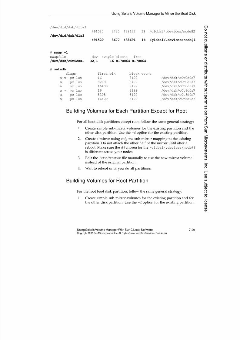
8/4/2019 Sun Cluster 3.2 Administration VC-ES-345
http://slidepdf.com/reader/full/sun-cluster-32-administration-vc-es-345 359/585
Using Solaris Volume Manager to Mirror the Boot Disk
Using Solaris Volume Manager With Sun Cluster Software 7-29Copyright2006 SunMicrosystems, Inc. AllRightsReserved. SunServices,RevisionA
/dev/did/dsk/d11s3
491520 3735 438633 1% /global/.devices/node@2
/dev/did/dsk/d1s3
491520 3677 438691 1% /global/.devices/node@1
# swap -l
swapfile dev swaplo blocks free
/dev/dsk/c0t0d0s1 32,1 16 8170064 8170064
# metadb
flags first blk block count
a m pc luo 16 8192 /dev/dsk/c0t0d0s7
a pc luo 8208 8192 /dev/dsk/c0t0d0s7
a pc luo 16400 8192 /dev/dsk/c0t0d0s7
a m pc luo 16 8192 /dev/dsk/c0t8d0s7a pc luo 8208 8192 /dev/dsk/c0t8d0s7
a pc luo 16400 8192 /dev/dsk/c0t8d0s7
Building Volumes for Each Partition Except for Root
For all boot disk partitions except root, follow the same general strategy:
1. Create simple sub-mirror volumes for the existing partition and theother disk partition. Use the -f option for the existing partition.
2. Create a mirror using only the sub-mirror mapping to the existingpartition. Do not attach the other half of the mirror until after areboot. Make sure the d# chosen for the /global/.devices/node@#is different across your nodes.
3. Edit the /etc/vfstab file manually to use the new mirror volumeinstead of the original partition.
4. Wait to reboot until you do all partitions.
Building Volumes for Root Partition
For the root boot disk partition, follow the same general strategy:
1. Create simple sub-mirror volumes for the existing partition and forthe other disk partition. Use the -f option for the existing partition.
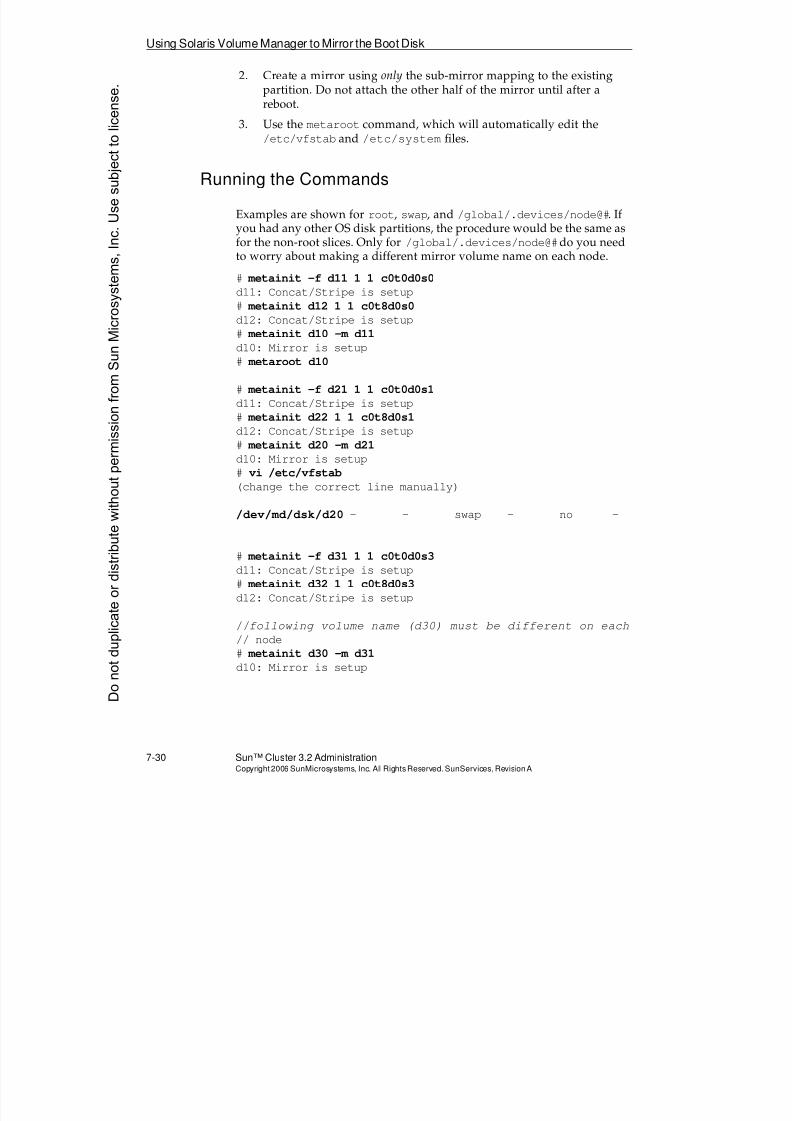
8/4/2019 Sun Cluster 3.2 Administration VC-ES-345
http://slidepdf.com/reader/full/sun-cluster-32-administration-vc-es-345 360/585
Using Solaris Volume Manager to Mirror the Boot Disk
7-30 Sun™ Cluster 3.2 AdministrationCopyright2006 SunMicrosystems, Inc. AllRights Reserved.SunServices,RevisionA
2. Create a mirror using only the sub-mirror mapping to the existingpartition. Do not attach the other half of the mirror until after areboot.
3. Use the metaroot command, which will automatically edit the/etc/vfstab and /etc/system files.
Running the Commands
Examples are shown for root, swap, and /global/.devices/node@#. Ifyou had any other OS disk partitions, the procedure would be the same asfor the non-root slices. Only for /global/.devices/node@#do you needto worry about making a different mirror volume name on each node.
# metainit -f d11 1 1 c0t0d0s0
d11: Concat/Stripe is setup
# metainit d12 1 1 c0t8d0s0d12: Concat/Stripe is setup
# metainit d10 -m d11
d10: Mirror is setup
# metaroot d10
# metainit -f d21 1 1 c0t0d0s1
d11: Concat/Stripe is setup
# metainit d22 1 1 c0t8d0s1
d12: Concat/Stripe is setup
# metainit d20 -m d21
d10: Mirror is setup
# vi /etc/vfstab
(change the correct line manually)
/dev/md/dsk/d20 - - swap - no -
# metainit -f d31 1 1 c0t0d0s3
d11: Concat/Stripe is setup
# metainit d32 1 1 c0t8d0s3
d12: Concat/Stripe is setup
//following volume name (d30) must be different on each
// node
# metainit d30 -m d31
d10: Mirror is setup
Donotduplicate
ordistributewithoutpermissionfrom SunMicrosystems,Inc.Usesubject
tolicense.
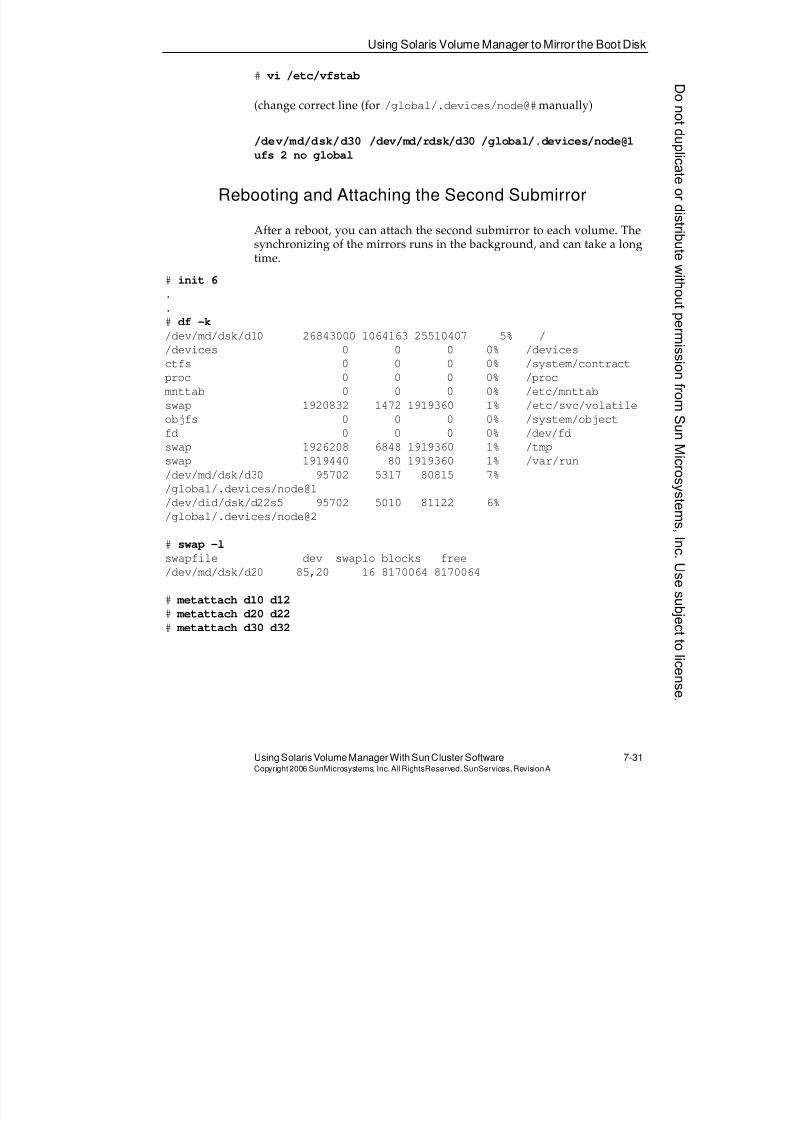
8/4/2019 Sun Cluster 3.2 Administration VC-ES-345
http://slidepdf.com/reader/full/sun-cluster-32-administration-vc-es-345 361/585
Using Solaris Volume Manager to Mirror the Boot Disk
Using Solaris Volume Manager With Sun Cluster Software 7-31Copyright2006 SunMicrosystems, Inc. AllRightsReserved. SunServices,RevisionA
# vi /etc/vfstab
(change correct line (for /global/.devices/node@#manually)
/dev/md/dsk/d30 /dev/md/rdsk/d30 /global/.devices/node@1
ufs 2 no global
Rebooting and Attaching the Second Submirror
After a reboot, you can attach the second submirror to each volume. Thesynchronizing of the mirrors runs in the background, and can take a longtime.
# init 6
.
.
# df -k
/dev/md/dsk/d10 26843000 1064163 25510407 5% /
/devices 0 0 0 0% /devices
ctfs 0 0 0 0% /system/contract
proc 0 0 0 0% /proc
mnttab 0 0 0 0% /etc/mnttab
swap 1920832 1472 1919360 1% /etc/svc/volatile
objfs 0 0 0 0% /system/object
fd 0 0 0 0% /dev/fd
swap 1926208 6848 1919360 1% /tmp
swap 1919440 80 1919360 1% /var/run
/dev/md/dsk/d30 95702 5317 80815 7%
/global/.devices/node@1
/dev/did/dsk/d22s5 95702 5010 81122 6%
/global/.devices/node@2
# swap -l
swapfile dev swaplo blocks free
/dev/md/dsk/d20 85,20 16 8170064 8170064
# metattach d10 d12
# metattach d20 d22
# metattach d30 d32
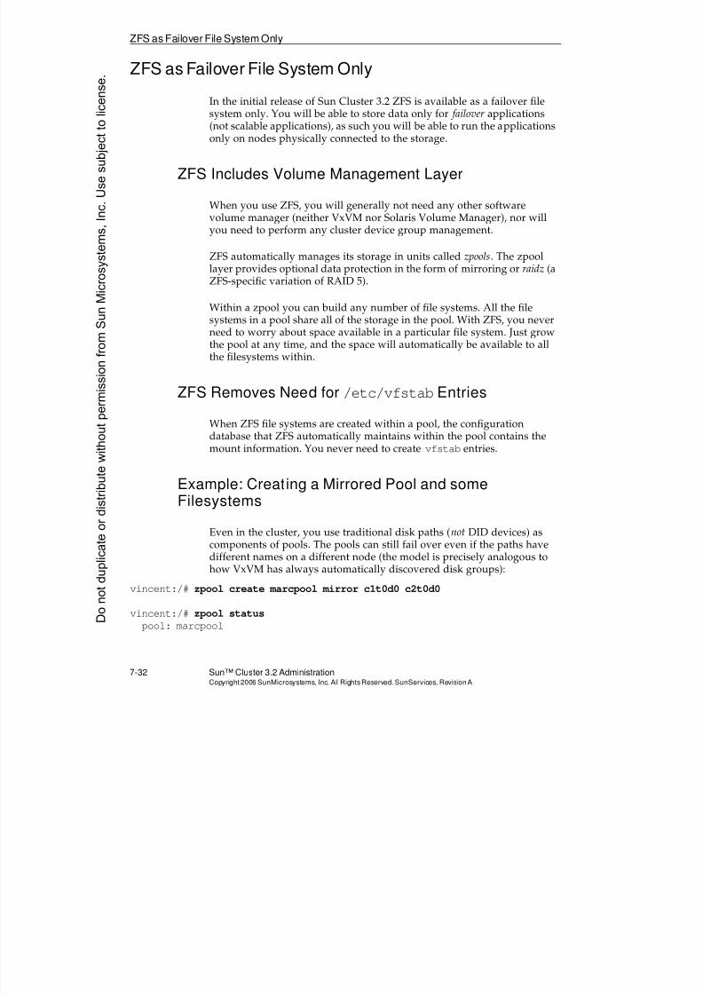
8/4/2019 Sun Cluster 3.2 Administration VC-ES-345
http://slidepdf.com/reader/full/sun-cluster-32-administration-vc-es-345 362/585
ZFS as Failover File System Only
7-32 Sun™ Cluster 3.2 AdministrationCopyright2006 SunMicrosystems, Inc. AllRights Reserved.SunServices,RevisionA
ZFS as Failover File System Only
In the initial release of Sun Cluster 3.2 ZFS is available as a failover filesystem only. You will be able to store data only for failover applications(not scalable applications), as such you will be able to run the applicationsonly on nodes physically connected to the storage.
ZFS Includes Volume Management Layer
When you use ZFS, you will generally not need any other softwarevolume manager (neither VxVM nor Solaris Volume Manager), nor willyou need to perform any cluster device group management.
ZFS automatically manages its storage in units called zpools. The zpool
layer provides optional data protection in the form of mirroring or raidz (aZFS-specific variation of RAID 5).
Within a zpool you can build any number of file systems. All the filesystems in a pool share all of the storage in the pool. With ZFS, you neverneed to worry about space available in a particular file system. Just growthe pool at any time, and the space will automatically be available to allthe filesystems within.
ZFS Removes Need for /etc/vfstabEntries
When ZFS file systems are created within a pool, the configurationdatabase that ZFS automatically maintains within the pool contains themount information. You never need to create vfstab entries.
Example: Creating a Mirrored Pool and someFilesystems
Even in the cluster, you use traditional disk paths (not DID devices) ascomponents of pools. The pools can still fail over even if the paths havedifferent names on a different node (the model is precisely analogous tohow VxVM has always automatically discovered disk groups):
vincent:/# zpool create marcpool mirror c1t0d0 c2t0d0
vincent:/# zpool status
pool: marcpoolDonotduplicate
ordistributewithoutpermissionfrom SunMicrosystems,Inc.Usesubject
tolicense.
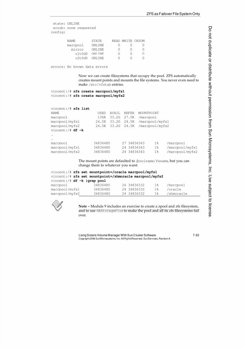
8/4/2019 Sun Cluster 3.2 Administration VC-ES-345
http://slidepdf.com/reader/full/sun-cluster-32-administration-vc-es-345 363/585
ZFS as Failover File System Only
Using Solaris Volume Manager With Sun Cluster Software 7-33Copyright2006 SunMicrosystems, Inc. AllRightsReserved. SunServices,RevisionA
state: ONLINE
scrub: none requested
config:
NAME STATE READ WRITE CKSUM
marcpool ONLINE 0 0 0
mirror ONLINE 0 0 0
c1t0d0 ONLINE 0 0 0
c2t0d0 ONLINE 0 0 0
errors: No known data errors
Now we can create filesystems that occupy the pool. ZFS automaticallycreates mount points and mounts the file systems. You never even need tomake /etc/vfstab entries.
vincent:/# zfs create marcpool/myfs1
vincent:/# zfs create marcpool/myfs2
vincent:/# zfs list
NAME USED AVAIL REFER MOUNTPOINT
marcpool 136K 33.2G 27.5K /marcpool
marcpool/myfs1 24.5K 33.2G 24.5K /marcpool/myfs1
marcpool/myfs2 24.5K 33.2G 24.5K /marcpool/myfs2
vincent:/# df -k
.
.
marcpool 34836480 27 34836343 1% /marcpool
marcpool/myfs1 34836480 24 34836343 1% /marcpool/myfs1
marcpool/myfs2 34836480 24 34836343 1% /marcpool/myfs2
The mount points are defaulted to / poolname/fsname, but you canchange them to whatever you want:
vincent:/# zfs set mountpoint=/oracle marcpool/myfs1
vincent:/# zfs set mountpoint=/shmoracle marcpool/myfs2
vincent:/# df -k |grep pool
marcpool 34836480 26 34836332 1% /marcpool
marcpool/myfs1 34836480 24 34836332 1% /oraclemarcpool/myfs2 34836480 24 34836332 1% /shmoracle
Note – Module 9 includes an exercise to create a zpool and zfs filesystem,and to use HAStoragePlus to make the pool and all its zfs filesystems failover.
8/4/2019 Sun Cluster 3.2 Administration VC-ES-345
http://slidepdf.com/reader/full/sun-cluster-32-administration-vc-es-345 364/585
Exercise: Configuring Solaris Volume Manager
7-34 Sun™ Cluster 3.2 AdministrationCopyright2006 SunMicrosystems, Inc. AllRights Reserved.SunServices,RevisionA
Exercise: Configuring Solaris Volume Manager
In this exercise, you complete the following tasks:
q Task 1 – Initializing the Solaris Volume Manager Local metadb
Replicasq Task 2 – Selecting the Solaris Volume Manager Demo Volume Disk
Drives
q Task 3 – Configuring Solaris Volume Manager Disksets
q Task 4 – Configuring Solaris Volume Manager DemonstrationVolumes
q Task 5 – Creating a Global nfs File System
q Task 6 – Creating a Global web File System
q Task 7 – Testing Global File Systemsq Task 8 – Managing Disk Device Groups
q Task 9 – Viewing and Managing Solaris Volume Manager DeviceGroups Using Sun Cluster Manager
q Task 10 (Optional) – Managing and Mirroring the Boot Disk WithSolaris Volume Manager
Preparation
This exercise assumes you are running the Sun Cluster 3.2 softwareenvironment on Solaris 10 OS.
At least one local disk on each node must have a small unused slice thatyou can use for the local metadb replicas. The examples in this exerciseuse slice 7 of the boot disk.
If you have encapsulated (but not mirrored) your root disk in a previousVERITAS Volume Manager lab, you can still do this lab if you have asecond local disk. To run Solaris Volume Manager, you must have at least
one local disk that has room for local metadb replicas and is not undercontrol of VERITAS Volume Manager.
Donotduplicate
ordistributewithoutpermissionfrom SunMicrosystems,Inc.Usesubject
tolicense.
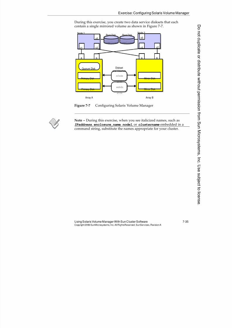
8/4/2019 Sun Cluster 3.2 Administration VC-ES-345
http://slidepdf.com/reader/full/sun-cluster-32-administration-vc-es-345 365/585
Exercise: Configuring Solaris Volume Manager
Using Solaris Volume Manager With Sun Cluster Software 7-35Copyright2006 SunMicrosystems, Inc. AllRightsReserved. SunServices,RevisionA
During this exercise, you create two data service disksets that eachcontain a single mirrored volume as shown in Figure 7-7.
Figure 7-7 Configuring Solaris Volume Manager
Note – During this exercise, when you see italicized names, such asIPaddress, enclosure_name, node1, or clustername embedded in acommand string, substitute the names appropriate for your cluster.
Node 1 Node 2Boot Disk Boot Disk
c1 c2
c0 c0
A B A B
Quorum Disk
Primary Disk
Primary Disk
Disksetand Volumes
nfsds
d100
webds
d100
Array A Array B
(replicas)(replicas)
Mirror Disk
Mirror Disk
c1c2
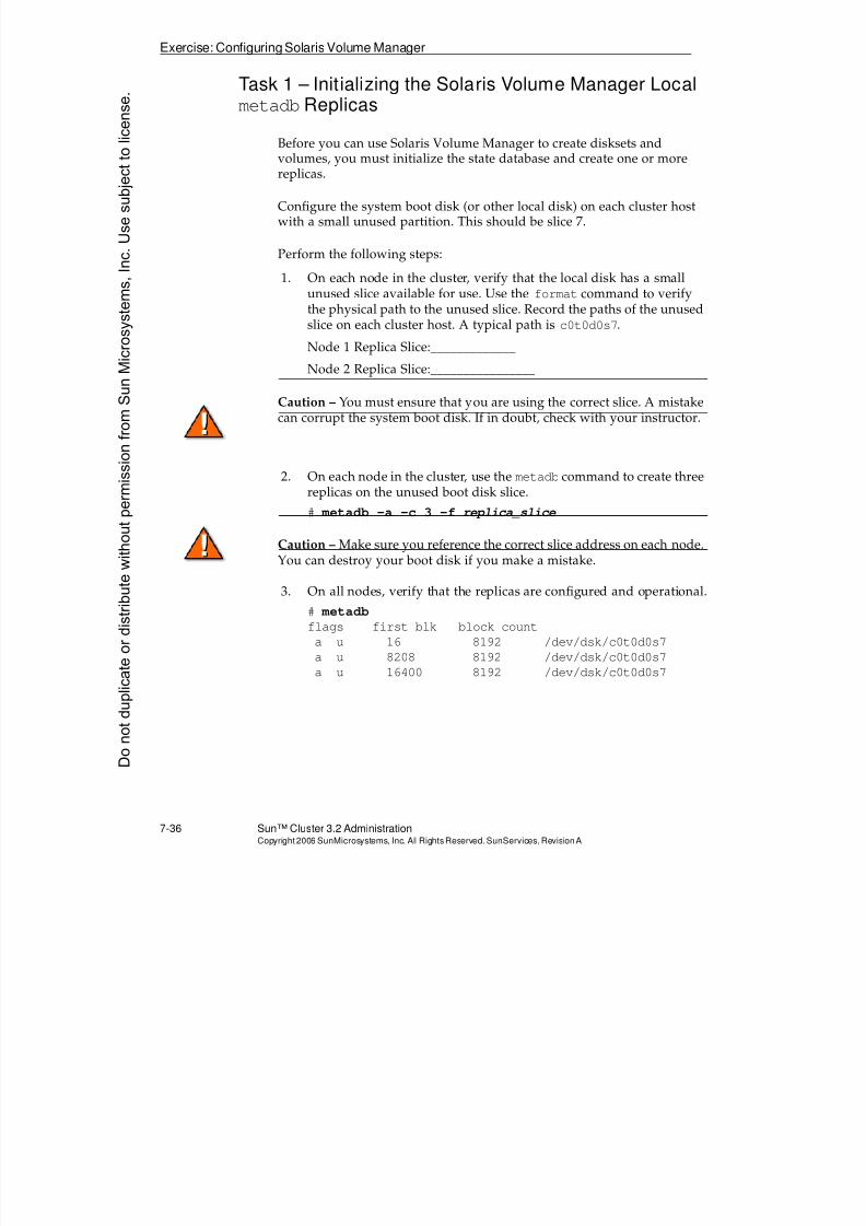
8/4/2019 Sun Cluster 3.2 Administration VC-ES-345
http://slidepdf.com/reader/full/sun-cluster-32-administration-vc-es-345 366/585
Exercise: Configuring Solaris Volume Manager
7-36 Sun™ Cluster 3.2 AdministrationCopyright2006 SunMicrosystems, Inc. AllRights Reserved.SunServices,RevisionA
Task 1 – Initializing the Solaris Volume Manager LocalmetadbReplicas
Before you can use Solaris Volume Manager to create disksets and
volumes, you must initialize the state database and create one or morereplicas.
Configure the system boot disk (or other local disk) on each cluster hostwith a small unused partition. This should be slice 7.
Perform the following steps:
1. On each node in the cluster, verify that the local disk has a smallunused slice available for use. Use the format command to verifythe physical path to the unused slice. Record the paths of the unused
slice on each cluster host. A typical path isc0t0d0s7
.Node 1 Replica Slice:_____________
Node 2 Replica Slice:________________
Caution – You must ensure that you are using the correct slice. A mistakecan corrupt the system boot disk. If in doubt, check with your instructor.
2. On each node in the cluster, use the metadb command to create three
replicas on the unused boot disk slice.# metadb -a -c 3 -f replica_slice
Caution – Make sure you reference the correct slice address on each node.You can destroy your boot disk if you make a mistake.
3. On all nodes, verify that the replicas are configured and operational.
# metadb
flags first blk block count
a u 16 8192 /dev/dsk/c0t0d0s7
a u 8208 8192 /dev/dsk/c0t0d0s7
a u 16400 8192 /dev/dsk/c0t0d0s7
Donotduplicate
ordistributewithoutpermissionfrom SunMicrosystems,Inc.Usesubject
tolicense.
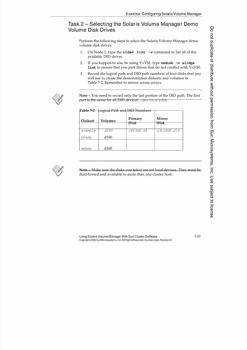
8/4/2019 Sun Cluster 3.2 Administration VC-ES-345
http://slidepdf.com/reader/full/sun-cluster-32-administration-vc-es-345 367/585
Exercise: Configuring Solaris Volume Manager
Using Solaris Volume Manager With Sun Cluster Software 7-37Copyright2006 SunMicrosystems, Inc. AllRightsReserved. SunServices,RevisionA
Task 2 – Selecting the Solaris Volume Manager DemoVolume Disk Drives
Perform the following steps to select the Solaris Volume Manager demo
volume disk drives:1. On Node 1, type the cldev list -v command to list all of the
available DID drives.
2. If you happen to also be using VxVM, type vxdisk -o alldgs
list to ensure that you pick drives that do not conflict with VxVM.
3. Record the logical path and DID path numbers of four disks that youwill use to create the demonstration disksets and volumes inTable 7-2. Remember to mirror across arrays.
Note – You need to record only the last portion of the DID path. The firstpart is the same for all DID devices: /dev/did/rdsk.
Note – Make sure the disks you select are not local devices. They must bedual-hosted and available to more than one cluster host.
Table 7-2 Logical Path and DID Numbers
Diskset Volumes PrimaryDisk
MirrorDisk
example d100 c2t3d0 d4 c3t18d0 d15
nfsds d100
webds d100
8/4/2019 Sun Cluster 3.2 Administration VC-ES-345
http://slidepdf.com/reader/full/sun-cluster-32-administration-vc-es-345 368/585
Exercise: Configuring Solaris Volume Manager
7-38 Sun™ Cluster 3.2 AdministrationCopyright2006 SunMicrosystems, Inc. AllRights Reserved.SunServices,RevisionA
Task 3 – Configuring Solaris Volume Manager Disksets
Perform the following steps to create demonstration disksets and volumesfor use in later exercises:
1. On Node 1, create the nfsds diskset, and configure the nodes thatare physically connected to it.
# metaset -s nfsds -a -h node1 node2
2. On Node 1, create the webds diskset and configure the nodes that arephysically connected to it.
# metaset -s webds -a -h node1 node2
3. Add the same nodes as diskset mediators to each diskset.
# metaset -s nfsds -a -m node1 node2
# metaset -s webds -a -m node1 node2
4. Add the two disks chosen previously, one from each array, to thenfsds diskset.
# metaset -s nfsds -a /dev/did/rdsk/dx \
/dev/did/rdsk/d y
5. Add the two disks chosen previously, one from each array, to thewebds diskset.
# metaset -s webds -a /dev/did/rdsk/dw \
/dev/did/rdsk/dz
6. Verify the status of the new disksets.
# metaset -s nfsds# metaset -s webds
# medstat -s nfsds
# medstat -s webds
# cldg status
Donotduplicate
ordistributewithoutpermissionfrom SunMicrosystems,Inc.Usesubject
tolicense.
8/4/2019 Sun Cluster 3.2 Administration VC-ES-345
http://slidepdf.com/reader/full/sun-cluster-32-administration-vc-es-345 369/585
Exercise: Configuring Solaris Volume Manager
Using Solaris Volume Manager With Sun Cluster Software 7-39Copyright2006 SunMicrosystems, Inc. AllRightsReserved. SunServices,RevisionA
Task 4 – Configuring Solaris Volume ManagerDemonstration Volumes
Perform the following steps on Node 1 to create a 500-Mbyte mirrored
volume in each diskset, as shown.
The nfsdsDiskset
Follow these steps to create the volume on the nfsds diskset:
1. Create a submirror on each of your disks in the nfsds diskset.
# metainit -s nfsds d0 1 1 /dev/did/rdsk/dx s0
# metainit -s nfsds d1 1 1 /dev/did/rdsk/d y s0
2. Create a mirror volume, d99, using the d0 submirror.
# metainit -s nfsds d99 -m d0
3. Attach the second submirror, d1, to the mirror volume d99.
# metattach -s nfsds d99 d1
4. Create a 500 Mbyte soft partition, d100, on top of your mirror. This isthe volume you will actually use for your file system data.
# metainit -s nfsds d100 -p d99 500m
5. Verify the status of the new volume.
# metastat -s nfsds
The webdsDiskset
Follow these steps to create the volume on the webds diskset. Because it isa different disk set, you can use the same volume names as you used fornfsds.
1. Create a submirror on each of your disks in the webds diskset.
# metainit -s webds d0 1 1 /dev/did/rdsk/dw s0
# metainit -s webds d1 1 1 /dev/did/rdsk/dzs0
2. Create a mirror volume, d99, using the d0 submirror.
# metainit -s webds d99 -m d0
3. Attach the second submirror, d1, to the mirror volume d99.
# metattach -s webds d99 d1
8/4/2019 Sun Cluster 3.2 Administration VC-ES-345
http://slidepdf.com/reader/full/sun-cluster-32-administration-vc-es-345 370/585
Exercise: Configuring Solaris Volume Manager
7-40 Sun™ Cluster 3.2 AdministrationCopyright2006 SunMicrosystems, Inc. AllRights Reserved.SunServices,RevisionA
4. Create a 500-Mbyte soft partition on top of your mirror. This is thevolume you will actually use for your file system data.
# metainit -s webds d100 -p d99 500m
5. Verify the status of the new volume.
# metastat -s webds
Task 5 – Creating a Global nfsFile System
Perform the following steps on Node 1 to create a global file system in thenfsds diskset:
1. On Node 1, create a file system on d100 in the nfsds diskset.
# newfs /dev/md/nfsds/rdsk/d100
2. On all nodes, create a global mount point for the new file system.
Note – If you have already done the VxVM exercises, and already have amounted /global/nfs file system, you can choose a different mountpoint for this one.
# mkdir /global/nfs
3. On all nodes, add a mount entry in the /etc/vfstab file for the newfile system with the global mount option.
/dev/md/nfsds/dsk/d100 /dev/md/nfsds/rdsk/d100 \
/global/nfs ufs 2 yes global
Note – Do not use the line continuation character (\) in the vfstab file.
4. On Node 1, mount the /global/nfs file system.
# mount /global/nfs
5. Verify that the file system is mounted and available on all nodes.
# mount
# ls /global/nfs
lost+found
Donotduplicate
ordistributewithoutpermissionfrom SunMicrosystems,Inc.Usesubject
tolicense.
8/4/2019 Sun Cluster 3.2 Administration VC-ES-345
http://slidepdf.com/reader/full/sun-cluster-32-administration-vc-es-345 371/585
Exercise: Configuring Solaris Volume Manager
Using Solaris Volume Manager With Sun Cluster Software 7-41Copyright2006 SunMicrosystems, Inc. AllRightsReserved. SunServices,RevisionA
Task 6 – Creating a Global webFile System
Perform the following steps on Node 1 to create a global file system in thewebds diskset:
1. On Node 1, create a file system on d100 in the webds diskset.# newfs /dev/md/webds/rdsk/d100
2. On all nodes, create a global mount point for the new file system.
Note – If you have already done the VxVM exercises, and already have amounted /global/web file system, you can choose a different mountpoint for this one.
# mkdir /global/web
3. On all nodes, add a mount entry in the /etc/vfstab file for the newfile system with the global mount option.
/dev/md/webds/dsk/d100 /dev/md/webds/rdsk/d100 \
/global/web ufs 2 yes global
Note – Do not use the line continuation character (\) in the vfstab file.
4. On Node 1, mount the /global/web file system.
# mount /global/web
5. Verify that the file system is mounted and available on all nodes.
# mount
# ls /global/web
lost+found
8/4/2019 Sun Cluster 3.2 Administration VC-ES-345
http://slidepdf.com/reader/full/sun-cluster-32-administration-vc-es-345 372/585
Exercise: Configuring Solaris Volume Manager
7-42 Sun™ Cluster 3.2 AdministrationCopyright2006 SunMicrosystems, Inc. AllRights Reserved.SunServices,RevisionA
Task 7 – Testing Global File Systems
Perform the following steps to confirm the general behavior of globallyavailable file systems in the Sun Cluster 3.2 software environment:
1. On Node 2, move into the /global/nfs file system.# cd /global/nfs
2. On Node 1, try to unmount the /global/nfsfile system. You shouldget an error that the file system is busy.
3. On Node 2, move out of the /global/nfsfile system (cd /) and tryto unmount it again on Node 1.
4. Mount the /global/nfs file system on Node 1.
5. Try unmounting and mounting /global/nfs from all nodes.
Task 8 – Managing Disk Device Groups
Perform the following steps to migrate a disk device group (diskset) between cluster nodes:
1. Make sure the device groups are online (to the Sun Cluster software).
# cldg status
Note – You can bring a device group online to a selected node as follows:# cldg switch -n node_to_switch_to devgrpname
2. Verify the current demonstration device group configuration.
# cldg show
3. Shut down Node 1.
The nfsds and webds disksets should automatically migrate toNode 2 (verify with the cldg status command).
4. Boot Node 1. Both disksets should remain mastered by Node 2.
5. Use the cldg switch command from either node to migrate thenfsds diskset to Node 1.
# cldg switch -n node1 nfsds
Donotduplicate
ordistributewithoutpermissionfrom SunMicrosystems,Inc.Usesubject
tolicense.
8/4/2019 Sun Cluster 3.2 Administration VC-ES-345
http://slidepdf.com/reader/full/sun-cluster-32-administration-vc-es-345 373/585
Exercise: Configuring Solaris Volume Manager
Using Solaris Volume Manager With Sun Cluster Software 7-43Copyright2006 SunMicrosystems, Inc. AllRightsReserved. SunServices,RevisionA
Task 9 – Viewing and Managing Solaris VolumeManager Device Groups Using Sun Cluster Manager
In this task you view and manage Solaris Volume Manager device groups
through Sun Cluster Manager. Perform the following steps on youradministration workstation or display station.
1. In a Web browser, log in to Sun Java Web Console on any clusternode:
https://nodename:6789
2. Enter the Sun Cluster Manager Application.
3. Open up the arrow pointing to the Storage folder on the left.
4. From the subcategories revealed for Storage, click Device Groups.
5. You will see error messages about the singleton device groups foreach DID. This is normal.
6. Click the name of your Solaris Volume Manager device groups (nearthe bottom of the list).
7. Use the Switch Primaries button to switch the primary for the devicegroup.
Task 10 (Optional) – Managing and Mirroring the BootDisk With Solaris Volume Manager
If you have time and interest, try this procedure. Typically, you would runit on all nodes but feel free to run it on one node only as a proof of concept.
This task assumes that you have a second drive with identical geometryto the first. If you do not, you can still perform the parts of the lab that donot refer to the second disk. That is, create mirrors with only one sub-mirror for each partition on your boot disk.
The example uses c0t8d0 as the second drive.
Repartitioning the Second Drive and AddingmetadbReplicas
Use the following commands to repartition the second drive and addmetadb replicas:
# prtvtoc /dev/rdsk/c0t0d0s0|fmthard -s - /dev/rdsk/c0t8d0s0
fmthard: New volume table of contents now in place.
8/4/2019 Sun Cluster 3.2 Administration VC-ES-345
http://slidepdf.com/reader/full/sun-cluster-32-administration-vc-es-345 374/585
Exercise: Configuring Solaris Volume Manager
7-44 Sun™ Cluster 3.2 AdministrationCopyright2006 SunMicrosystems, Inc. AllRights Reserved.SunServices,RevisionA
# metadb -a -c 3 c0t8d0s7
Using the metadbCommand to Verify metadbReplicas
Use the following command to verify the metadb replicas:
# metadb
flags first blk block count
a u 16 8192 /dev/dsk/c0t0d0s7
a u 8208 8192 /dev/dsk/c0t0d0s7
a u 16400 8192 /dev/dsk/c0t0d0s7
a u 16 8192 /dev/dsk/c0t8d0s7
a u 8208 8192 /dev/dsk/c0t8d0s7
a u 16400 8192 /dev/dsk/c0t8d0s7
Making Mirrors for Non-Root Slices
For each non-root slice on your drive (including swap but not includingthe metadbpartition), make submirrors from the partition on each of yourtwo disks. Make a mirrored volume using the first submirror. Do notattach the second submirror. Edit the vfstab file manually to referencethe mirror volume instead of the partition or DID device. Do not rebootyet.
The example shows the procedure for the swap partition and for the/global/.devices/node@#
partition. If you are doing this on more thanone node, make sure the volume number chosen for the/global/.devices/node@#mirror is different on each node.
Example for Swap Partition
# metainit -f d21 1 1 c0t0d0s1
d11: Concat/Stripe is setup
# metainit d22 1 1 c0t8d0s1
d12: Concat/Stripe is setup
# metainit d20 -m d21
d10: Mirror is setup# vi /etc/vfstab
(change correct line manually)
/dev/md/dsk/d20 - - swap - no -
Donotduplicate
ordistributewithoutpermissionfrom SunMicrosystems,Inc.Usesubject
tolicense.
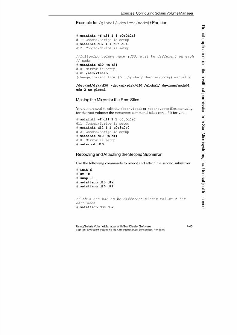
8/4/2019 Sun Cluster 3.2 Administration VC-ES-345
http://slidepdf.com/reader/full/sun-cluster-32-administration-vc-es-345 375/585
Exercise: Configuring Solaris Volume Manager
Using Solaris Volume Manager With Sun Cluster Software 7-45Copyright2006 SunMicrosystems, Inc. AllRightsReserved. SunServices,RevisionA
Example for /global/.devices/node@#Partition
# metainit -f d31 1 1 c0t0d0s3
d11: Concat/Stripe is setup
# metainit d32 1 1 c0t8d0s3d12: Concat/Stripe is setup
//following volume name (d30) must be different on each
// node
# metainit d30 -m d31
d10: Mirror is setup
# vi /etc/vfstab
(change correct line (for /global/.devices/node@# manually)
/dev/md/dsk/d30 /dev/md/rdsk/d30 /global/.devices/node@1
ufs 2 no global
Making the Mirror for the Root Slice
You do not need to edit the /etc/vfstab or /etc/system files manuallyfor the root volume; the metaroot command takes care of it for you.
# metainit -f d11 1 1 c0t0d0s0
d11: Concat/Stripe is setup
# metainit d12 1 1 c0t8d0s0
d12: Concat/Stripe is setup
# metainit d10 -m d11d10: Mirror is setup
# metaroot d10
Rebooting and Attaching the Second Submirror
Use the following commands to reboot and attach the second submirror:
# init 6
# df -k
# swap -l
# metattach d10 d12# metattach d20 d22
// this one has to be different mirror volume # for
each node
# metattach d30 d32

8/4/2019 Sun Cluster 3.2 Administration VC-ES-345
http://slidepdf.com/reader/full/sun-cluster-32-administration-vc-es-345 376/585
Exercise Summary
7-46 Sun™ Cluster 3.2 AdministrationCopyright2006 SunMicrosystems, Inc. AllRights Reserved.SunServices,RevisionA
Exercise Summary
?
!
Discussion – Take a few minutes to discuss what experiences, issues, ordiscoveries you had during the lab exercises.
q Experiences
q Interpretations
q Conclusions
q Applications
Donotduplicate
ordistributewithoutpermissionfrom SunMicrosystems,Inc.Usesubject
tolicense.
8/4/2019 Sun Cluster 3.2 Administration VC-ES-345
http://slidepdf.com/reader/full/sun-cluster-32-administration-vc-es-345 377/585
8-1Copyright2006 SunMicrosystems, Inc. AllRights Reserved.SunServices,RevisionA
Module 8
ManagingthePublicNetworkWithIPMP
Objectives
Upon completion of this module, you should be able to:
q Define the purpose of IPMP
q Define the concepts of an IPMP group
q List examples of network adapters in IPMP groups on a singleSolaris™ OS server
q Describe the operation of the in.mpathd daemon
q List the options to the ifconfig command that support IPMP andconfigure IPMP using /etc/hostname.xxxfiles
q Perform a forced failover of an adapter in an IPMP group
q Configure IPMP manually with ifconfig commands
q Describe the integration of IPMP into the Sun™ Cluster softwareenvironment
)
8/4/2019 Sun Cluster 3.2 Administration VC-ES-345
http://slidepdf.com/reader/full/sun-cluster-32-administration-vc-es-345 378/585
Relevance
8-2 Sun™Cluster 3 .2AdministrationCopyright2006 SunMicrosystems, Inc. AllRights Reserved.SunServices,RevisionA
Relevance
?!
Discussion – The following questions are relevant to understanding the
content of this module:q Should you configure IPMP before or after you install the Sun
Cluster software?
q Why is IPMP required even if you do not have redundant networkadapters?
q Is the configuration of IPMP any different in the Sun Clusterenvironment than on a stand-alone Solaris OS?
q Is the behavior of IPMP any different in the Sun Clusterenvironment?
Donotduplicate
ordistributewithoutpermissionfrom SunMicrosystems,Inc.Usesubject
tolicense.
8/4/2019 Sun Cluster 3.2 Administration VC-ES-345
http://slidepdf.com/reader/full/sun-cluster-32-administration-vc-es-345 379/585
Additional Resources
Managing the Public Network With IPMP 8-3Copyright2006 SunMicrosystems, Inc. AllRightsReserved. SunServices,RevisionA
Additional Resources
Additional resources – The following references provide additional
information on the topics described in this module:q Sun Cluster System Administration Guide for Solaris OS, part number
819-2971
q Sun Cluster Software Installation Guide for Solaris OS, part number 819-2970
q Sun Cluster Concepts Guide for Solaris OS, part number 819-2969
q Solaris Administration Guide: IP Services, part number 816-4554
8/4/2019 Sun Cluster 3.2 Administration VC-ES-345
http://slidepdf.com/reader/full/sun-cluster-32-administration-vc-es-345 380/585
Introducing IPMP
8-4 Sun™Cluster 3 .2AdministrationCopyright2006 SunMicrosystems, Inc. AllRights Reserved.SunServices,RevisionA
Introducing IPMP
IPMP has been a standard part of the base Solaris OS since Solaris 8 OSUpdate 3 (01/01).
IPMP enables you to configure redundant network adapters, on the sameserver (node) and on the same subnet, as an IPMP failover group.
The IPMP daemon detects failures and repairs of network connectivity foradapters, and provides failover and failback of IP addresses amongmembers of the same group. Existing TCP connections to the IP addressesthat fail over as part of an IPMP group are interrupted for short amountsof time without data loss and without being disconnected.
In the Sun Cluster 3.2 software environment, you must use IPMP to
manage any public network adapters on which you will be placing the IPaddresses associated with applications running in the cluster.
These application IP addresses are implemented by mechanisms knownas LogicalHostnameand SharedAddress resources. The configuration ofthese resources requires that the public network adapters being used areunder the control of IPMP. Module 9, “Introducing Data Services,Resource Groups, and HA-NFS,” and Module 10, “Configuring ScalableServices and Advanced Resource Group Relationships,” provide detailabout the proper configuration of applications and their IP addresses inthe Sun Cluster software environment.
Donotduplicate
ordistributewithoutpermissionfrom SunMicrosystems,Inc.Usesubject
tolicense.
8/4/2019 Sun Cluster 3.2 Administration VC-ES-345
http://slidepdf.com/reader/full/sun-cluster-32-administration-vc-es-345 381/585
Describing General IPMPConcepts
Managing the Public Network With IPMP 8-5Copyright2006 SunMicrosystems, Inc. AllRightsReserved. SunServices,RevisionA
Describing General IPMP Concepts
IPMP allows you to group together network adapters for redundancy.Members of the same IPMP group are identified by a common groupname. This can be any alphanumeric name. The group name ismeaningful only inside a single Solaris OS server.
Defining IPMP Group Requirements
You must observe the following rules when configuring an IPMP group:
q A network adapter can be a member of only one group.
q When both IPv4 and IPv6 are configured on a physical adapter, thegroup names are always the same (and thus need not be specified
explicitly for IPv6).q All members of a group must be on the same subnet. The members,
if possible, should be connected to physically separate switches onthe same subnet.
q Adapters on different subnets must be in different groups.
q You can have multiple groups on the same subnet.
q You can have a group with only one member. However, there is noredundancy and there is no automatic failover.
q Each Ethernet adapter must have a unique MAC address. This isachieved by setting the local-mac-address?variable to true in theOpenBoot™ PROM.
q Network adapters in the same group must be the same type. Forexample, you cannot combine Ethernet adapters and AsynchronousTransfer Mode (ATM) adapters in the same group.
q In Solaris 9 OS, when more than one adapter is in an IPMP group,each adapter requires a dedicated test IP address, or test interface.This is an extra static IP for each group member specificallyconfigured for the purposes of testing the health of the adapter using
ping traffic.The test interface enables test traffic on all the members of the IPMPgroup. This is the reason that local-mac-address?=true isrequired for IPMP.
8/4/2019 Sun Cluster 3.2 Administration VC-ES-345
http://slidepdf.com/reader/full/sun-cluster-32-administration-vc-es-345 382/585
Describing General IPMP Concepts
8-6 Sun™Cluster 3 .2AdministrationCopyright2006 SunMicrosystems, Inc. AllRights Reserved.SunServices,RevisionA
q Solaris 10 OS does not require test addresses, even with multipleadapters in a group. If you set up adapters in Solaris 10 OS IPMPgroups without test addresses, the health of the adapter isdetermined solely by the link state of the adapter.
Note – Using IPMP without test addresses reduces network traffic andreduces the administrative strain of allocating the addresses. However, thetesting is less robust. For example, this author has personally experiencedadapters with a valid link state but broken receive logic. Such an adapterwould be properly faulted using test addresses. The remaining examplesin the module focus on creating IPMP configurations with test addresses.
q If both IPv4 and IPv6 are configured on the same adapters, it ispossible to have test addresses for both IPv4 and IPv6, but you donot have to. If a failure is detected (even if you have only an IPv4 test
address), all IPv4 and IPv6 addresses (except the test address) failover to the other physical adapter.
If you do choose to have an IPv6 test address, that test address willalways be the link-local IPv6 address (the address automaticallyassigned to the adapter, that can only be used on the local subnet).See ‘‘Configuring Adapters for IPV6 (Optional)’’ on page 8-16 to seehow to set up IPv6 on your adapters.
Donotduplicate
ordistributewithoutpermissionfrom SunMicrosystems,Inc.Usesubject
tolicense.
8/4/2019 Sun Cluster 3.2 Administration VC-ES-345
http://slidepdf.com/reader/full/sun-cluster-32-administration-vc-es-345 383/585
Describing General IPMPConcepts
Managing the Public Network With IPMP 8-7Copyright2006 SunMicrosystems, Inc. AllRightsReserved. SunServices,RevisionA
Configuring Standby Adapters in a Group
In an IPMP group with two or more members, you can configure anadapter as a standby adapter for the group. Standby adapters have thefollowing properties:
q You are allowed (and must) configure only the test interface on theadapter. Any attempt to manually configure any other addressesfails.
q Additional IP addresses are added to the adapter only as a result of afailure of another member of the group.
q The standby adapter is preferred as a failover target if anothermember of the group fails.
q You must have at least one member of the group that is not astandby adapter.
Note – The examples of two-member IPMP groups in the Sun Clustersoftware environment will not use any standby adapters. This allows theSun Cluster software to balance additional IP addresses associated withapplications across both members of the group.
If you had a three-member IPMP group in the Sun Cluster softwareenvironment, setting up one of the members as a standby would still be avalid option.
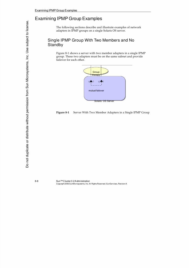
8/4/2019 Sun Cluster 3.2 Administration VC-ES-345
http://slidepdf.com/reader/full/sun-cluster-32-administration-vc-es-345 384/585
Examining IPMP Group Examples
8-8 Sun™Cluster 3 .2AdministrationCopyright2006 SunMicrosystems, Inc. AllRights Reserved.SunServices,RevisionA
Examining IPMP Group Examples
The following sections describe and illustrate examples of networkadapters in IPMP groups on a single Solaris OS server.
Single IPMP Group With Two Members and NoStandby
Figure 8-1 shows a server with two member adapters in a single IPMPgroup. These two adapters must be on the same subnet and providefailover for each other.
Figure 8-1 Server With Two Member Adapters in a Single IPMP Group
Solaris OS Server
qfe0 qfe4
Group:therapy
mutual failover
Donotduplicate
ordistributewithoutpermissionfrom SunMicrosystems,Inc.Usesubject
tolicense.
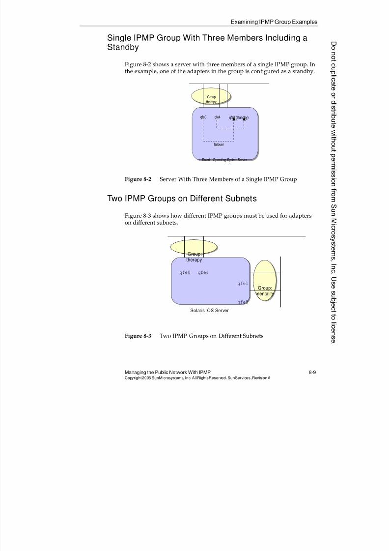
8/4/2019 Sun Cluster 3.2 Administration VC-ES-345
http://slidepdf.com/reader/full/sun-cluster-32-administration-vc-es-345 385/585
Examining IPMP Group Examples
Managing the Public Network With IPMP 8-9Copyright2006 SunMicrosystems, Inc. AllRightsReserved. SunServices,RevisionA
Single IPMP Group With Three Members Including aStandby
Figure 8-2 shows a server with three members of a single IPMP group. In
the example, one of the adapters in the group is configured as a standby.
Figure 8-2 Server With Three Members of a Single IPMP Group
Two IPMP Groups on Different Subnets
Figure 8-3 shows how different IPMP groups must be used for adapters
on different subnets.
Figure 8-3 Two IPMP Groups on Different Subnets
Solaris Operating System Server
qfe0 qfe4
Group:
therapy
failover
qfe8 (standby)
Solaris OS Server
qfe0 qfe4
qfe1
qfe5
Group:mentality
Group:therapy
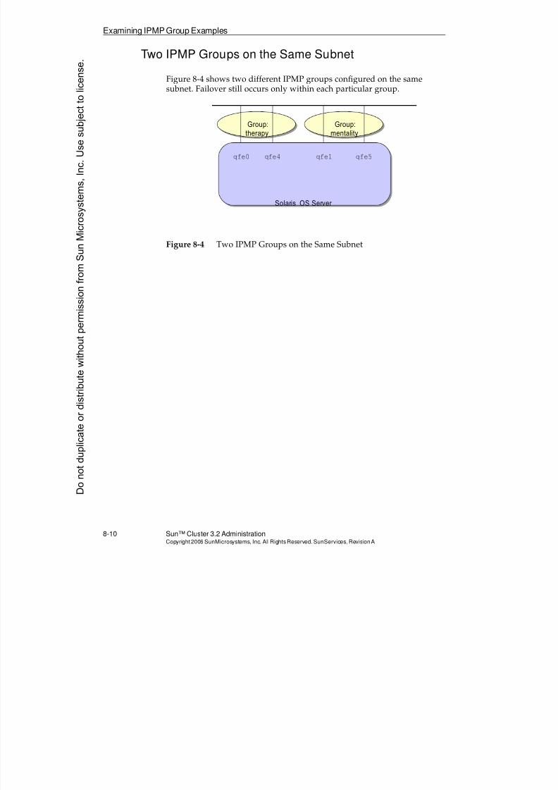
8/4/2019 Sun Cluster 3.2 Administration VC-ES-345
http://slidepdf.com/reader/full/sun-cluster-32-administration-vc-es-345 386/585
Examining IPMP Group Examples
8-10 Sun™ Cluster 3.2 AdministrationCopyright2006 SunMicrosystems, Inc. AllRights Reserved.SunServices,RevisionA
Two IPMP Groups on the Same Subnet
Figure 8-4 shows two different IPMP groups configured on the samesubnet. Failover still occurs only within each particular group.
Figure 8-4 Two IPMP Groups on the Same Subnet
Solaris OS Server
qfe0 qfe4 qfe1 qfe5
Group:therapy
Group:mentality
Donotduplicate
ordistributewithoutpermissionfrom SunMicrosystems,Inc.Usesubject
tolicense.
8/4/2019 Sun Cluster 3.2 Administration VC-ES-345
http://slidepdf.com/reader/full/sun-cluster-32-administration-vc-es-345 387/585
Describing IPMP
Managing the Public Network With IPMP 8-11Copyright2006 SunMicrosystems, Inc. AllRightsReserved. SunServices,RevisionA
Describing IPMP
The in.mpathd daemon controls the behavior of IPMP. This behavior can be summarized as a three-part scheme:
q Network path failure detectionq Network path failover
q Network path failback
The in.mpathd daemon starts automatically when an adapter is made amember of an IPMP group through the ifconfig command.
Network Path Failure Detection
The following paragraphs describe the functionality of the in.mpathd
daemon in a configuration using test addresses. In the Solaris 10 OS,without test addresses, adapter failure detection and repair is based solelyon the link state of the adapter.
When test addresses are used, the in.mpathd daemon sends InternetControl Message Protocol (ICMP) echo probes (pings) to the targetsconnected to the link on all adapters that belong to a group to detectfailures and repair. The test address is used as the source address of thesepings.
Note – Using test addresses, even in Solaris 10, is more robust. You canhave broken adapters, ports, or cables and still have a valid link state.
The in.mpathd daemon automatically chooses targets in the followingorder:
1. Targets are chosen from the routing table in memory in the followingorder:
a. Host
b. Network
c. Default
2. If no targets are discovered through the routing table, ther targetsare.discovered by a ping command to the 224.0.0.1 (all-hosts)multicast IP address.
8/4/2019 Sun Cluster 3.2 Administration VC-ES-345
http://slidepdf.com/reader/full/sun-cluster-32-administration-vc-es-345 388/585
Describing IPMP
8-12 Sun™ Cluster 3.2 AdministrationCopyright2006 SunMicrosystems, Inc. AllRights Reserved.SunServices,RevisionA
To ensure that each adapter in the group functions properly, thein.mpathd daemon probes all the targets separately through all theadapters in the multipathing group, using each adapter’s test address. Ifthere are no replies to five consecutive probes, the in.mpathd daemonconsiders the adapter as having failed. The probing rate depends on the
failure detection time (FDT). The default value for failure detection time is10 seconds. For a failure detection time of 10 seconds, the probing rate isapproximately one probe every two seconds.
You might need to manipulate the choice of ping targets. For example,you might have default routers that are explicitly configured not toanswer pings.
One strategy is to enter specific static host routes to IP addresses that areon the same subnet as your adapters. These will then be chosen first as thetargets. For example, if you wanted to use 192.168.1.39 and
192.168.1.5 as the targets, you could run these commands:
# route add -host 192.168.1.39 192.168.1.39 -static
# route add -host 192.168.1.5 192.168.1.5 -static
You can put these commands in a boot script. The Solaris AdministrationGuide: IP Services from docs.sun.com listed in the resources section at the beginning of this module suggests making a boot script/etc/rc2.d/S70ipmp.targets. This works on both Solaris 9 and Solaris10.
Network Path Failover
After a failure is detected, failover of all network access occurs from thefailed adapter to another functional adapter in the group. If you haveconfigured a standby adapter, the in.mpathd daemon chooses that forfailover of IP addresses and multicast memberships. If you have notconfigured a standby adapter, in.mpathd chooses the adapter with theleast number of IP addresses. The new adapter assumes all of the IPaddresses of the failed adapter, except for the test address.
Network Path Failback
The in.mpathd daemon detects if the failed path has been repaired. Atthis time the IP addresses moved in the failover will be returned to theiroriginal path, assuming failback is enabled.
Donotduplicate
ordistributewithoutpermissionfrom SunMicrosystems,Inc.Usesubject
tolicense.
8/4/2019 Sun Cluster 3.2 Administration VC-ES-345
http://slidepdf.com/reader/full/sun-cluster-32-administration-vc-es-345 389/585
Configuring IPMP
Managing the Public Network With IPMP 8-13Copyright2006 SunMicrosystems, Inc. AllRightsReserved. SunServices,RevisionA
Configuring IPMP
This section outlines how IPMP is configured directly through options tothe ifconfig command.
Most of the time, you will just specify the correct IPMP-specific ifconfigoptions in the /etc/hostname.xxx files. After these are correct, younever have to change them again.
Examining New ifconfigOptions for IPMP
Several new ifconfig options have been added for use with IPMP. Theyare the following:
q group groupname– Adapters on the same subnet are placed in afailover group by configuring them with the same group name. The
group name can be any name and must be unique only within asingle Solaris OS (node). It is irrelevant if you have the same ordifferent group names across the different nodes of a cluster.
q -failover – Use this option to demarcate the test address for eachadapter. The test interface is the only interface on an adapter thatdoes not fail over to another adapter when a failure occurs.
q deprecated – This option, while not required, is typically used onthe test interfaces. Any IP address marked with this option is not
used as the source IP address for any client connections initiatedfrom this machine.
q standby – This option, when used with the physical adapter(-failover deprecated standby), turns that adapter into astandby-only adapter. No other virtual interfaces can be configuredon that adapter until a failure occurs on another adapter within thegroup.
q addif – Use this option to create the next available virtual interfacefor the specified adapter. The maximum number of virtual interfacesper physical interface is 8192.
q removeif– Use this option to remove a virtual interface, by justgiving the IP address assigned to the interface. You do not need toknow the virtual interface number.
8/4/2019 Sun Cluster 3.2 Administration VC-ES-345
http://slidepdf.com/reader/full/sun-cluster-32-administration-vc-es-345 390/585
Configuring IPMP
8-14 Sun™ Cluster 3.2 AdministrationCopyright2006 SunMicrosystems, Inc. AllRights Reserved.SunServices,RevisionA
Putting Test Addresses on Physical or Vir tualInterfaces
IPMP was designed so that the required test interface for each member of
an IPMP group can be either on the physical interface (for example,qfe0
)or on a virtual interface (for example, qfe0:1, created with theifconfig xxx addif command).
There were at one time many existing IPMP documents written with thetest IP on the physical interface because it looks cleanest to have only thevirtual interfaces failing over to other adapters and the IP on the physicalinterface always staying where it is.
The convention changed due to a bug relating to having a deprecatedflag on the physical adapter. Refer to bug #4710499 for more information.
Note – The bug concerns failure of certain RPC applications, specificallywhen the deprecated flag is on the physical adapter. You should alwaysuse the deprecatedflag with test addresses; therefore, you should ensurethe test addresses are not on the physical adapter. The examples in thismodule follow the convention of placing the test interface on a virtualinterface, when given the choice.
Using ifconfigCommands to Configure IPMPWhile most of the time you will set up your /etc/hostname.xxx filesonce and never have to worry about IPMP configuration again, theseexamples show using the ifconfig command directly with theIPMP-specific options.
The /etc/hosts fragment shows the dedicated IP address for the testinterface for each adapter. While it is not required to have host names forthese, remember that these IPs are reserved.
# cat /etc/hosts.
#physical host address
172.20.4.192 vincent
# test addresses for vincent (node 1)
172.20.4.194 vincent-qfe1-test
172.20.4.195 vincent-qfe2-testDonotduplicate
ordistributewithoutpermissionfrom SunMicrosystems,Inc.Usesubject
tolicense.
8/4/2019 Sun Cluster 3.2 Administration VC-ES-345
http://slidepdf.com/reader/full/sun-cluster-32-administration-vc-es-345 391/585
Configuring IPMP
Managing the Public Network With IPMP 8-15Copyright2006 SunMicrosystems, Inc. AllRightsReserved. SunServices,RevisionA
# ifconfig qfe1 vincent group therapy netmask + broadcast + up
# ifconfig qfe1 addif vincent-qfe1-test -failover deprecated \
netmask + broadcast + up
# ifconfig qfe2 plumb
# ifconfig qfe2 vincent-qfe2-test group therapy -failover deprecated \
netmask + broadcast + up
# ifconfig -a
.
qfe1: flags=1000843<UP,BROADCAST,RUNNING,MULTICAST,IPv4> mtu 1500 index 2
inet 172.20.4.192 netmask ffffff00 broadcast 172.20.4.255
groupname therapy
ether 8:0:20:f1:2b:d
qfe1:1:flags=9040843<UP,BROADCAST,RUNNING,MULTICAST,DEPRECATED,IPv4,NOFAILOVER> mtu 1500 index 2
inet 172.20.4.194 netmask ffffff00 broadcast 172.20.4.255
qfe2:flags=9040843<UP,BROADCAST,RUNNING,MULTICAST,DEPRECATED,IPv4,NOFAILO
VER> mtu 1500 index 3
inet 172.20.4.195 netmask ffffff00 broadcast 172.20.4.255
groupname therapy
ether 8:0:20:f1:2b:e
Configuring the /etc/hostname.xxxFiles for IPMP
Usually, you do not need to manually use ifconfig commands. Instead,the ifconfig commands are run automatically at Solaris OS boot time because they are present in the /etc/hostname.xxx files.
The new format of these files (since Solaris 8 OS) allows you to put all theoptions to the ifconfig command within these files.
You can omit the netmask + broadcast + from these files because thisis always automatically applied by the Solaris OS boot process as a group
for all of the interfaces that have been configured.# cat /etc/hostname.qfe1
vincent group therapy netmask + broadcast + up
addif vincent-qfe1-test -failover deprecated netmask + broadcast + up
# cat /etc/hostname.qfe2
vincent-qfe2-test group therapy -failover deprecated \
netmask + broadcast + up
8/4/2019 Sun Cluster 3.2 Administration VC-ES-345
http://slidepdf.com/reader/full/sun-cluster-32-administration-vc-es-345 392/585
Configuring IPMP
8-16 Sun™ Cluster 3.2 AdministrationCopyright2006 SunMicrosystems, Inc. AllRights Reserved.SunServices,RevisionA
Configuring Adapters for IPV6 (Optional)
If you want to support application-specific IP addresses that use IPv6, youmust manually configure your adapters for IPv6. If you do not want touse any IPv6 on your public network, you do not need to configure IPv6
on them.
You can choose to configure IPV6 with or without an IPV6 test address.You already have an IPV4 test address, so you do not need to also have anIPV6 test address. If you do not want an IPV6 test address, you can createempty file names for the IPV6 interfaces. If you reboot, IPV6 is enabled onthe interfaces with the same group name as the IPV4 interfaces, withoutan IPV6 test address.
# touch /etc/hostname6.qfe1
# touch /etc/hostname6.qfe2
# init 6
Alternatively, you can choose to have an IPV6 test address. The onlyaddress that can serve this purpose is the link-local address, which isautomatically assigned to the interface and can be used only on the localsubnet; therefore, you can still have very simple IPV6 adapterconfiguration files:
# vi /etc/hostname6.qfe1
-failover up
# vi /etc/hostname6.qfe2
-failover up# init 6
Using IPV6 Test Address Only
It is possible to configure IPV6 test addresses only; that is, to configureIPV4 without any test addresses and then configure IPV6 with testaddresses, as in the example in the previous section.
The advantage is that you do not have to use any space in your IPV4public network address range for test addresses.
Note – You would have to have some external machines outside thecluster also configured with IPV6 to answer the ping. Claiming that thenodes can answer each other is not a highly-available solution!
Donotduplicate
ordistributewithoutpermissionfrom SunMicrosystems,Inc.Usesubject
tolicense.
8/4/2019 Sun Cluster 3.2 Administration VC-ES-345
http://slidepdf.com/reader/full/sun-cluster-32-administration-vc-es-345 393/585
Configuring IPMP
Managing the Public Network With IPMP 8-17Copyright2006 SunMicrosystems, Inc. AllRightsReserved. SunServices,RevisionA
The in.mpathdConfiguration File
The in.mpathd daemon uses the settings in the /etc/default/mpathd
configuration file to invoke multipathing. Changes to this file are read bythe in.mpathd daemon at startup and on a SIGHUP. This file contains the
following default settings and information:
#
# Time taken by mpathd to detect a NIC failure in ms.
# The minimum time that can be specified is 100 ms.
#
FAILURE_DETECTION_TIME=10000
#
# Failback is enabled by default. To disable failback
# turn off this option
#
FAILBACK=yes#
# By default only interfaces configured as part of
# multipathing groups are tracked. Turn off this
# option to track all network interfaces on the system
#
TRACK_INTERFACES_ONLY_WITH_GROUPS=yes
Note – Generally, you do not need to edit the default/etc/default/mpathd configuration file.
The three settings you can alter in this file are:
q FAILURE_DETECTION_TIME – You can lower the value of thisparameter. If the load on the network is too great, the system cannotmeet the failure detection time value. Then the in.mpathd daemonprints a message on the console, indicating that the time cannot bemet. It also prints the time that it can meet currently. If the responsecomes back correctly, the in.mpathd daemon meets the failuredetection time provided in this file.
q FAILBACK – After a failover, failbacks take place when the failedadapter is repaired. However, the in.mpathd daemon does not fail back the addresses if the FAILBACK option is set to no.
q TRACK_INTERFACES_ONLY_WITH_GROUPS– In stand-alone servers,you can set this to no so that in.mpathd monitors traffic even onadapters not in groups. In the cluster environment make sure youleave the value yes so that private transport adapters are not probed.
8/4/2019 Sun Cluster 3.2 Administration VC-ES-345
http://slidepdf.com/reader/full/sun-cluster-32-administration-vc-es-345 394/585
Performing Failover and FailbackManually
8-18 Sun™ Cluster 3.2 AdministrationCopyright2006 SunMicrosystems, Inc. AllRights Reserved.SunServices,RevisionA
Performing Failover and Failback Manually
You can do a forced failover of an adapter in an IPMP group. Thefollowing is an example:
# if_mpadm -d qfe1
This command causes IPMP to behave as if qfe1 had failed. All IPaddresses, except the test interface, are failed over to another member ofthe group. The adapter is marked down and will not be accessed byin.mpathd until reenabled.
To reenable an adapter after this operation, use:
# if_mpadm -r qfe1
This command allows the adapter to take back the IP addresses to whichit was originally assigned, assuming FAILBACK=yes is set in the/etc/default/mpathdfile.
Donotduplicate
ordistributewithoutpermissionfrom SunMicrosystems,Inc.Usesubject
tolicense.
8/4/2019 Sun Cluster 3.2 Administration VC-ES-345
http://slidepdf.com/reader/full/sun-cluster-32-administration-vc-es-345 395/585
Configuring IPMP in the Sun Cluster 3.2Environment
Managing the Public Network With IPMP 8-19Copyright2006 SunMicrosystems, Inc. AllRightsReserved. SunServices,RevisionA
Configuring IPMP in the Sun Cluster 3.2 Environment
There are no special cluster-related tools for configuring IPMP in theSun Cluster 3.2 environment. IPMP is configured on each node exactly asin a nonclustered environment.
Configuring IPMP Before or After Cluster Installation
If you have /etc/hostname.xxx files without IPMP groups, scinstallautomatically rewrites the files so that each such adapter is a member ofan IPMP group, as in the following example:
vincent:/# cat /etc/hostname.qfe1
vincent group sc_ipmp0 -failover
You will likely still need to correctly customize multi-adapter IPMP group by hand, to use the appropriate test addresses. The file created byscinstall uses the data address (for example, the node address) as thetest address, but you will want a different test address. To customize yourconfiguration, you can choose to wait until after scinstall, as you aredoing in this module (where you will be replacing some files rewritten byscinstall), or you can configure IPMP before scinstall.
You might choose to make IPMP configuration part of your Solaris OS JumpStart software installation, by copying in the correct
/etc/hostname.xxxfiles as part of a JumpStart™ software finish script.
Using Same Group Names on Different Nodes
It makes no difference to IPMP whether you use the same group names ordifferent group names for IPMP across nodes. IPMP itself is aware only ofwhat is going on in the local Solaris OS.
It is a helpful convention to use the same group names to indicate groupsof adapters on different nodes that are connected to the same subnet.

8/4/2019 Sun Cluster 3.2 Administration VC-ES-345
http://slidepdf.com/reader/full/sun-cluster-32-administration-vc-es-345 396/585
Configuring IPMP in the Sun Cluster 3.2Environment
8-20 Sun™ Cluster 3.2 AdministrationCopyright2006 SunMicrosystems, Inc. AllRights Reserved.SunServices,RevisionA
Understanding Standby and Failback
It is unlikely that you want to use a standby adapter in a two-memberIPMP group in the cluster environment. If you do, the Sun Clustersoftware will be unable to load-balance additional application-related IP
addresses across the members of the group.
Keep FAILBACK=yes in the /etc/default/mpathdfile. Sun Clustersoftware is automatically trying to load-balance additional IP addressesacross the members of the group. It makes sense that you want them torebalance when a repair is detected.
Donotduplicate
ordistributewithoutpermissionfrom SunMicrosystems,Inc.Usesubject
tolicense.
8/4/2019 Sun Cluster 3.2 Administration VC-ES-345
http://slidepdf.com/reader/full/sun-cluster-32-administration-vc-es-345 397/585
Integrating IPMP Into the Sun Cluster 3.2Software Environment
Managing the Public Network With IPMP 8-21Copyright2006 SunMicrosystems, Inc. AllRightsReserved. SunServices,RevisionA
Integrating IPMP Into the Sun Cluster 3.2 SoftwareEnvironment
There is nothing special about IPMP itself within the cluster. In the cluster
environment, as in a noncluster environment, in.mpathd is concernedwith probing network adapters only on a single Solaris OS, and managesfailovers and failbacks between the adapters in a group.
The Sun Cluster software environment, however, needs additionalcapability wrapped around IPMP to do the following:
q Store cluster-wide status of IPMP groups on each node in the CCR,and enable retrieval of this status with the clnode status -m
command
q Facilitate application failover in the case where all members of an
IPMP group on one node have failed, but the corresponding groupon the same subnet on another node has a healthy adapter
Clearly, IPMP itself is unaware of any of these cluster requirements.Instead, the Sun Cluster 3.2 software uses a cluster-specific publicnetwork management daemon (pnmd) to perform this cluster integration.
Capabilities of the pnmdDaemon in Sun Cluster 3.2Software
In the cluster environment, the pnmd daemon has the followingcapabilities:
q Populate CCR with public network adapter status
q Facilitate application failover
When pnmd detects that all members of a local IPMP group have failed, itconsults a file named /var/cluster/run/pnm_callbacks. This filecontains entries that would have been created by the activation ofLogicalHostname and SharedAddress resources. (There is moreinformation about this in Module 9, “Introducing Data Services, ResourceGroups, and HA-NFS,” and Module 10, “Configuring Scalable Servicesand Advanced Resource Group Relationships.”)
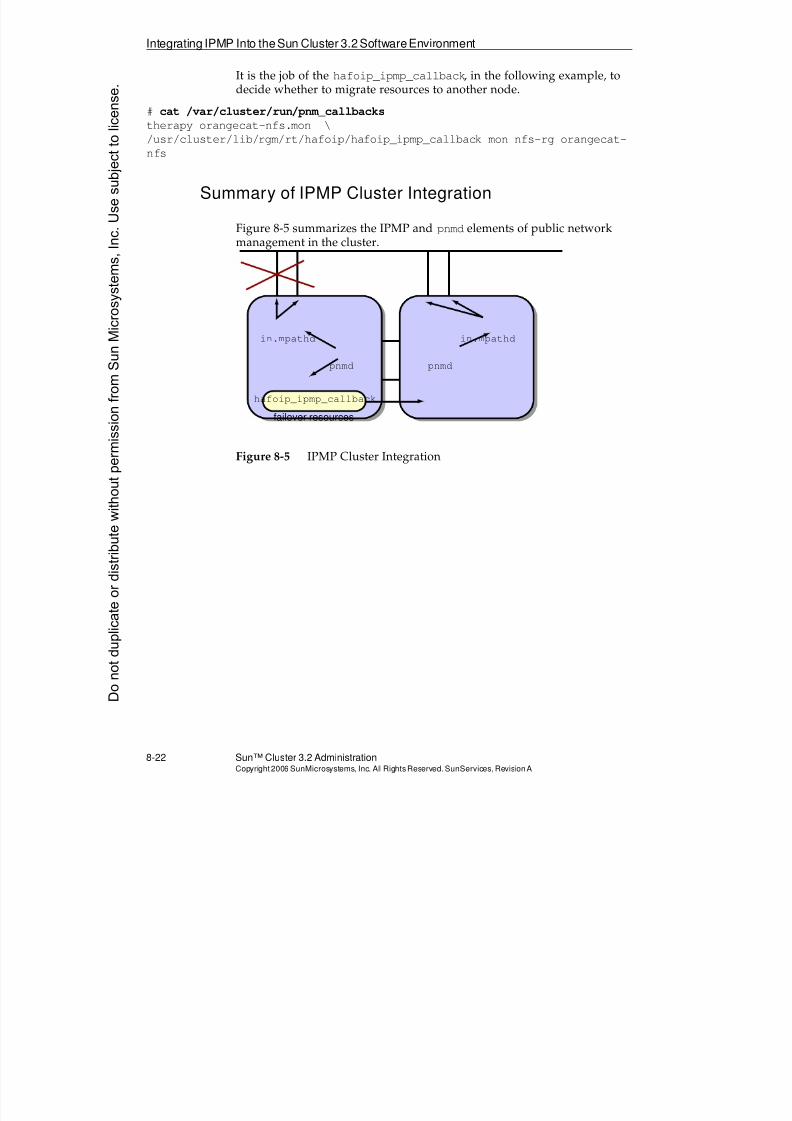
8/4/2019 Sun Cluster 3.2 Administration VC-ES-345
http://slidepdf.com/reader/full/sun-cluster-32-administration-vc-es-345 398/585
Integrating IPMP Into theSun Cluster 3.2 SoftwareEnvironment
8-22 Sun™ Cluster 3.2 AdministrationCopyright2006 SunMicrosystems, Inc. AllRights Reserved.SunServices,RevisionA
It is the job of the hafoip_ipmp_callback, in the following example, todecide whether to migrate resources to another node.
# cat /var/cluster/run/pnm_callbacks
therapy orangecat-nfs.mon \
/usr/cluster/lib/rgm/rt/hafoip/hafoip_ipmp_callback mon nfs-rg orangecat-
nfs
Summary of IPMP Cluster Integration
Figure 8-5 summarizes the IPMP and pnmd elements of public networkmanagement in the cluster.
Figure 8-5 IPMP Cluster Integration
failover resources
hafoip_ipmp_callback
in.mpathd in.mpathd
pnmd pnmd
Donotduplicate
ordistributewithoutpermissionfrom SunMicrosystems,Inc.Usesubject
tolicense.
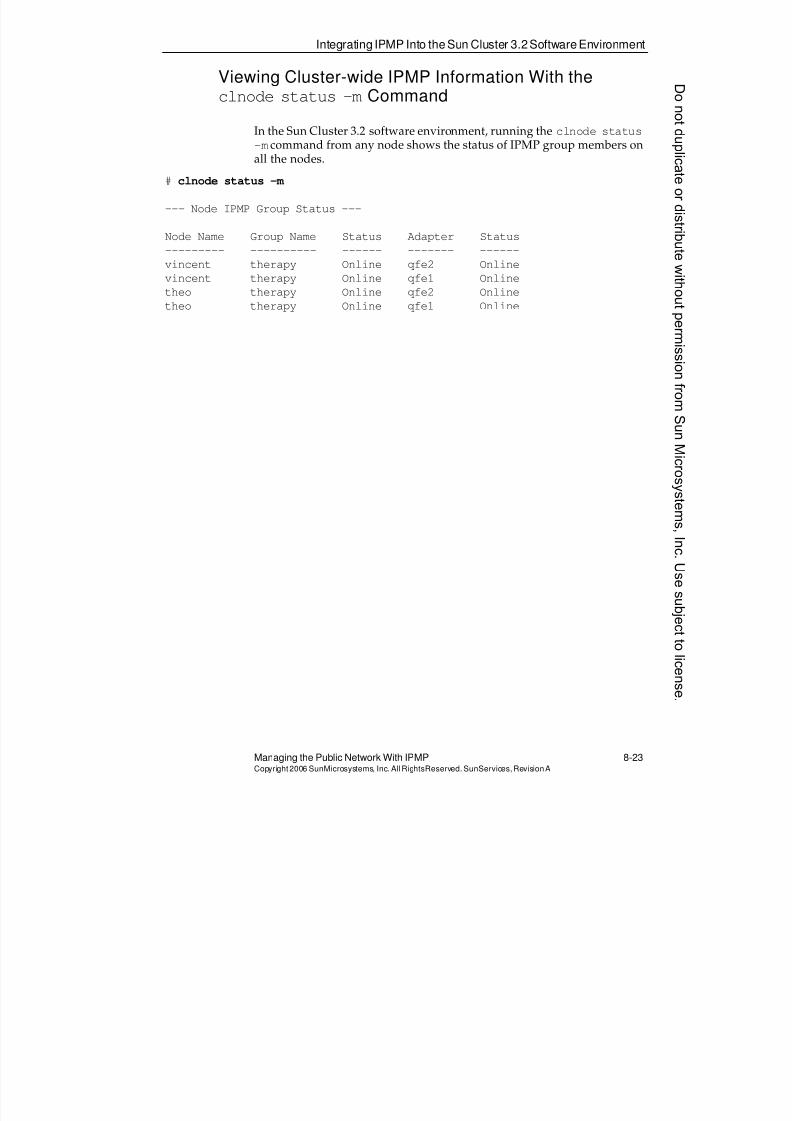
8/4/2019 Sun Cluster 3.2 Administration VC-ES-345
http://slidepdf.com/reader/full/sun-cluster-32-administration-vc-es-345 399/585
Integrating IPMP Into the Sun Cluster 3.2Software Environment
Managing the Public Network With IPMP 8-23Copyright2006 SunMicrosystems, Inc. AllRightsReserved. SunServices,RevisionA
Viewing Cluster-wide IPMP Information With theclnode status -m Command
In the Sun Cluster 3.2 software environment, running the clnode status
-mcommand from any node shows the status of IPMP group members onall the nodes.
# clnode status -m
--- Node IPMP Group Status ---
Node Name Group Name Status Adapter Status
--------- ---------- ------ ------- ------
vincent therapy Online qfe2 Online
vincent therapy Online qfe1 Online
theo therapy Online qfe2 Online
theo therapy Online qfe1 Online
8/4/2019 Sun Cluster 3.2 Administration VC-ES-345
http://slidepdf.com/reader/full/sun-cluster-32-administration-vc-es-345 400/585
Exercise: Configuring and Testing IPMP
8-24 Sun™ Cluster 3.2 AdministrationCopyright2006 SunMicrosystems, Inc. AllRights Reserved.SunServices,RevisionA
Exercise: Configuring and Testing IPMP
Perform the following tasks on all cluster nodes. It is assumed that theSun Cluster software is installed and operational, and that the only IPMPconfiguration is the single-adapter group called sc_ipmp0 automaticallycreated by scinstall.
In this exercise, you complete the following tasks:
q Task 1 – Verifying the local-mac-address?Variable
q Task 2 – Verifying the Adapters for the IPMP Group
q Task 3 – Verifying or Entering Test Addresses in the /etc/hosts File
q Task 4 – Creating /etc/hostname.xxx Files
q Task 5 – Rebooting and Verifying That IPMP Is Configured
q Task 6 – Verifying IPMP Failover and Failback
Preparation
No preparation is required for this exercise.
Task 1 – Verifying the local-mac-address?Variable
Perform the following steps on each node in the cluster:
1. Verify that the EEPROM local-mac-address? variable is set totrue:
# eeprom "local-mac-address?"
The variable is set to true by the scinstall utility at clusterinstallation time, so the only reason it should be false now is if itwere changed manually. If it needs to be changed to true, do sonow.
Donotduplicate
ordistributewithoutpermissionfrom SunMicrosystems,Inc.Usesubject
tolicense.
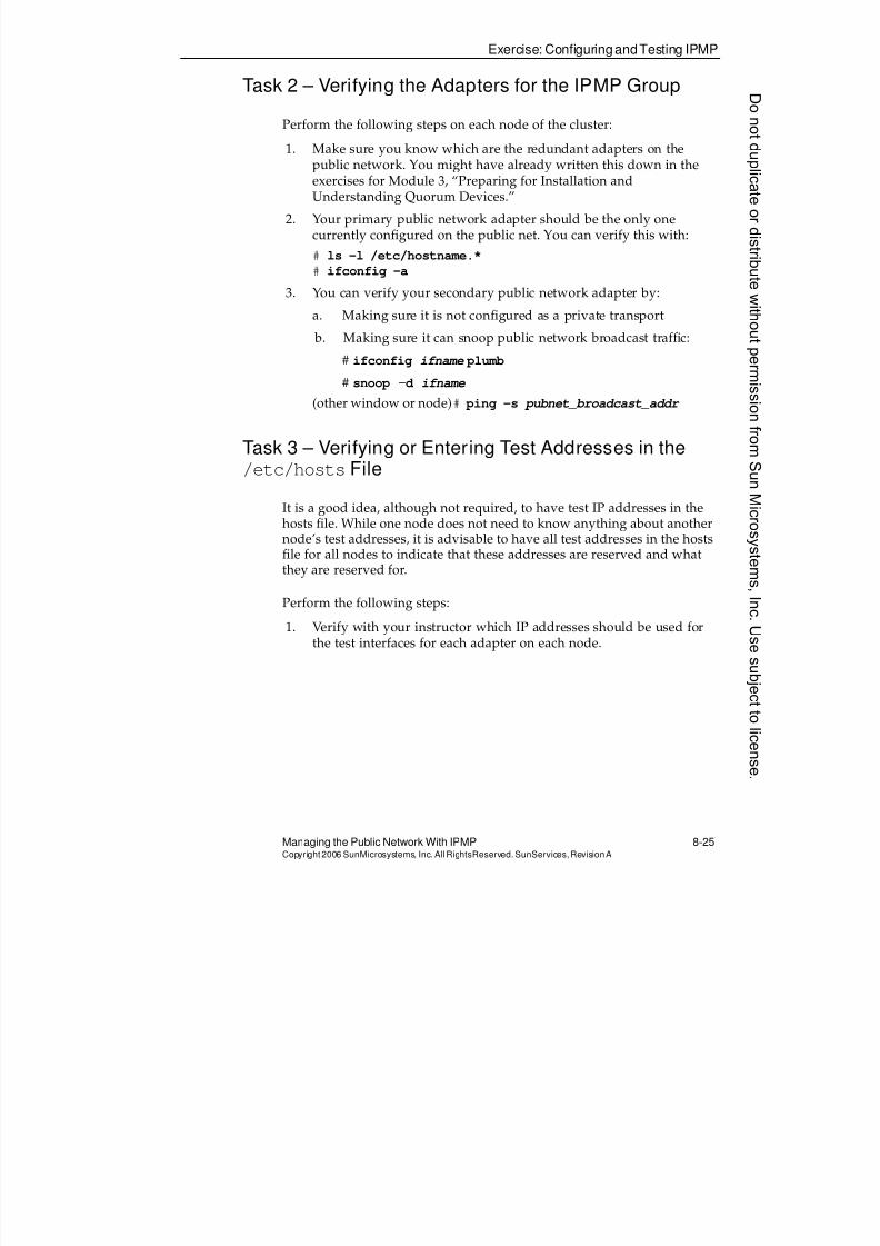
8/4/2019 Sun Cluster 3.2 Administration VC-ES-345
http://slidepdf.com/reader/full/sun-cluster-32-administration-vc-es-345 401/585
Exercise: ConfiguringandTesting IPMP
Managing the Public Network With IPMP 8-25Copyright2006 SunMicrosystems, Inc. AllRightsReserved. SunServices,RevisionA
Task 2 – Verifying the Adapters for the IPMP Group
Perform the following steps on each node of the cluster:
1. Make sure you know which are the redundant adapters on the
public network. You might have already written this down in theexercises for Module 3, “Preparing for Installation andUnderstanding Quorum Devices.”
2. Your primary public network adapter should be the only onecurrently configured on the public net. You can verify this with:
# ls -l /etc/hostname.*
# ifconfig -a
3. You can verify your secondary public network adapter by:
a. Making sure it is not configured as a private transport
b. Making sure it can snoop public network broadcast traffic:
# ifconfig ifname plumb
# snoop -d ifname
(other window or node)# ping -s pubnet_broadcast_addr
Task 3 – Verifying or Entering Test Addresses in the/etc/hostsFile
It is a good idea, although not required, to have test IP addresses in thehosts file. While one node does not need to know anything about anothernode’s test addresses, it is advisable to have all test addresses in the hostsfile for all nodes to indicate that these addresses are reserved and whatthey are reserved for.
Perform the following steps:
1. Verify with your instructor which IP addresses should be used forthe test interfaces for each adapter on each node.
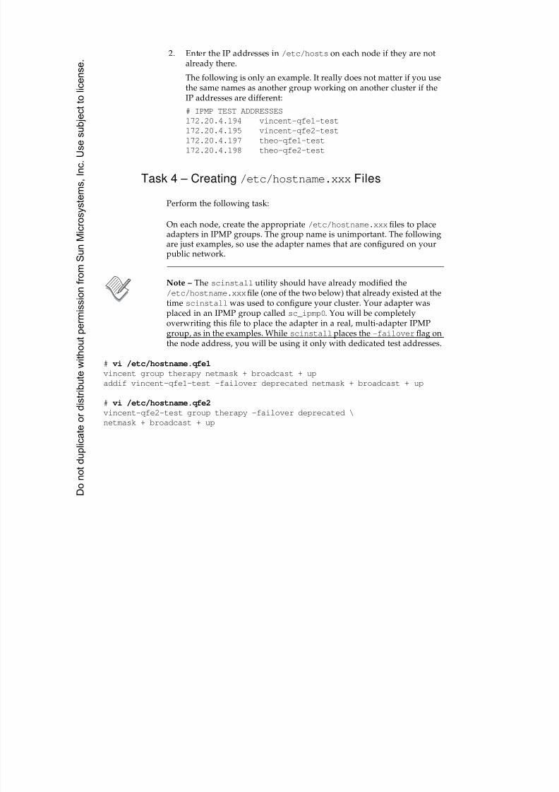
8/4/2019 Sun Cluster 3.2 Administration VC-ES-345
http://slidepdf.com/reader/full/sun-cluster-32-administration-vc-es-345 402/585
2. Enter the IP addresses in /etc/hosts on each node if they are notalready there.
The following is only an example. It really does not matter if you usethe same names as another group working on another cluster if theIP addresses are different:
# IPMP TEST ADDRESSES
172.20.4.194 vincent-qfe1-test
172.20.4.195 vincent-qfe2-test
172.20.4.197 theo-qfe1-test
172.20.4.198 theo-qfe2-test
Task 4 – Creating /etc/hostname.xxxFiles
Perform the following task:
On each node, create the appropriate /etc/hostname.xxxfiles to placeadapters in IPMP groups. The group name is unimportant. The followingare just examples, so use the adapter names that are configured on yourpublic network.
Note – The scinstall utility should have already modified the/etc/hostname.xxxfile (one of the two below) that already existed at thetime scinstall was used to configure your cluster. Your adapter wasplaced in an IPMP group called sc_ipmp0. You will be completely
overwriting this file to place the adapter in a real, multi-adapter IPMPgroup, as in the examples. While scinstallplaces the -failoverflag onthe node address, you will be using it only with dedicated test addresses.
# vi /etc/hostname.qfe1
vincent group therapy netmask + broadcast + up
addif vincent-qfe1-test -failover deprecated netmask + broadcast + up
# vi /etc/hostname.qfe2
vincent-qfe2-test group therapy -failover deprecated \
netmask + broadcast + up
Donotduplicate
ordistributewithoutpermissionfrom SunMicrosystems,Inc.Usesubject
tolicense.
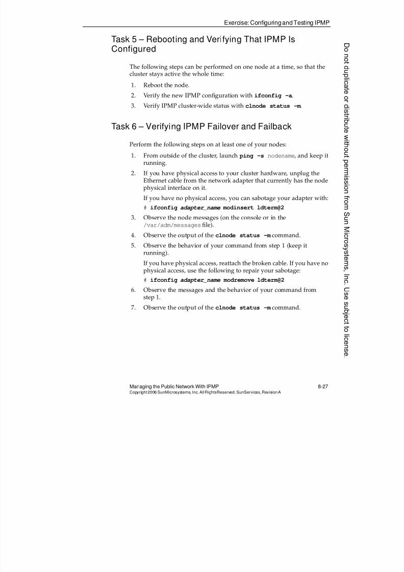
8/4/2019 Sun Cluster 3.2 Administration VC-ES-345
http://slidepdf.com/reader/full/sun-cluster-32-administration-vc-es-345 403/585
Exercise: ConfiguringandTesting IPMP
Managing the Public Network With IPMP 8-27Copyright2006 SunMicrosystems, Inc. AllRightsReserved. SunServices,RevisionA
Task 5 – Rebooting and Verifying That IPMP IsConfigured
The following steps can be performed on one node at a time, so that the
cluster stays active the whole time:1. Reboot the node.
2. Verify the new IPMP configuration with ifconfig -a.
3. Verify IPMP cluster-wide status with clnode status -m .
Task 6 – Verifying IPMP Failover and Failback
Perform the following steps on at least one of your nodes:
1. From outside of the cluster, launch ping -s nodename, and keep itrunning.
2. If you have physical access to your cluster hardware, unplug theEthernet cable from the network adapter that currently has the nodephysical interface on it.
If you have no physical access, you can sabotage your adapter with:
# ifconfig adapter_name modinsert ldterm@2
3. Observe the node messages (on the console or in the/var/adm/messages file).
4. Observe the output of the clnode status -m command.
5. Observe the behavior of your command from step 1 (keep itrunning).
If you have physical access, reattach the broken cable. If you have nophysical access, use the following to repair your sabotage:
# ifconfig adapter_name modremove ldterm@2
6. Observe the messages and the behavior of your command fromstep 1.
7. Observe the output of the clnode status -m command.

8/4/2019 Sun Cluster 3.2 Administration VC-ES-345
http://slidepdf.com/reader/full/sun-cluster-32-administration-vc-es-345 404/585
Do not duplicate or distribute without permission from Sun Microsystems, Inc. U
8/4/2019 Sun Cluster 3.2 Administration VC-ES-345
http://slidepdf.com/reader/full/sun-cluster-32-administration-vc-es-345 405/585
9-1Copyright2006 SunMicrosystems, Inc. AllRights Reserved.SunServices,RevisionA
Module 9
Introducing Data Services, ResourceGroups,and HA-NFS
Objectives
Upon completion of this module, you should be able to:
q Describe how data service agents enable a data service in a cluster tooperate properly
q List the components of a data service agent
q Describe data service packaging, installation, and registration
q Describe the primary purpose of resource groups
q Differentiate between failover and scalable data services
q Describe how to use special resource types
q
List the components of a resource groupq Differentiate between standard, extension, and resource group
properties
q Register resource types
q Configure resource groups and resources
q Perform manual control and switching of resources and resourcegroups
8/4/2019 Sun Cluster 3.2 Administration VC-ES-345
http://slidepdf.com/reader/full/sun-cluster-32-administration-vc-es-345 406/585
Relevance
9-2 Sun™Cluster 3 .2AdministrationCopyright2006 SunMicrosystems, Inc. AllRights Reserved.SunServices,RevisionA
Relevance
?!
Discussion – The following questions are relevant to understanding the
content of this module:q What is a data service agent for the Sun™ Cluster 3.2 software?
q What is involved in fault monitoring a data service?
q What is the implication of having multiple applications in the samefailover resource group?
q How do you distinguish the resources representing differentinstances of the same application?
q What are the specific requirements for setting up NFS in the SunCluster 3.2 software environment?
Donotduplicate
ordistributewithoutpermissionfrom SunMicrosystems,Inc.Usesubject
tolicense.

8/4/2019 Sun Cluster 3.2 Administration VC-ES-345
http://slidepdf.com/reader/full/sun-cluster-32-administration-vc-es-345 407/585
Additional Resources
Introducing Data Services, Resource Groups, and HA-NFS 9-3Copyright2006 SunMicrosystems, Inc. AllRightsReserved. SunServices,RevisionA
Additional Resources
Additional resources – The following references provide additional
information on the topics described in this module:q Sun Cluster System Administration Guide for Solaris™ OS, part number
819-2971
q Sun Cluster Software Installation Guide for Solaris OS, part number 819-2970
q Sun Cluster Concepts Guide for Solaris OS, part number 819-2969
8/4/2019 Sun Cluster 3.2 Administration VC-ES-345
http://slidepdf.com/reader/full/sun-cluster-32-administration-vc-es-345 408/585
Introducing Data Services in theCluster
9-4 Sun™Cluster 3 .2AdministrationCopyright2006 SunMicrosystems, Inc. AllRights Reserved.SunServices,RevisionA
Introducing Data Services in the Cluster
The Sun Cluster 3.2 software framework makes applications HA,minimizing application interruptions after any single failure in the cluster.
In addition, some applications, such as Apache web server software, aresupported not only with HA features, but also in a scalable configuration.This configuration allows the service to run on multiple nodes of thecluster simultaneously while providing a single IP address to the client.
Solaris 10 OS Non-Global Zones Act as Virtual Nodesfor Data Services
On the Solaris 10 OS, the entire framework described in this module andthe next module treats every non-global zone as a virtual node. That is,non-global zones can host clustered failover and scalable applications.
The intention of this feature is to allow the flexibility of configuring non-global zones on multiple nodes, and having your application fail over (or be load balanced) between non-global zones of different nodes. You mightprefer to have applications running in non-global zones for a variety ofreasons, including the security sandbox that they provide (you could giveapplication administrators the root password to a non-global zone, andthey are only super within that zone).
While it is not strictly the intention of the feature, you could even haveapplications that fail over between non-global zones of the same physicalnode. With the zone integration feature, a data-service developer withaccess only to a one-node cluster can experiment with real applicationfailover between non-global zones on the node.
Some applications, such as NFS, are not supported in non-global zones.This is typically an application or OS restriction, not a cluster restriction.
Off-the-Shelf Application
For most applications supported in the Sun Cluster software environment,software customization is not required to enable the application to runcorrectly in the cluster. A Sun Cluster 3.2 software agent is provided toenable the data service to run correctly in the cluster environment.
Donotduplicate
ordistributewithoutpermissionfrom SunMicrosystems,Inc.Usesubject
tolicense.
8/4/2019 Sun Cluster 3.2 Administration VC-ES-345
http://slidepdf.com/reader/full/sun-cluster-32-administration-vc-es-345 409/585
Introducing Data Services in the Cluster
Introducing Data Services, Resource Groups, and HA-NFS 9-5Copyright2006 SunMicrosystems, Inc. AllRightsReserved. SunServices,RevisionA
Application Requirements
You should identify requirements for all of the data services before you begin Solaris OS and Sun Cluster software installation. Failure to do somight result in installation errors that require you to completely reinstall
the Solaris OS and Sun Cluster software.
Determining the Location of the Application Binaries
You can install the application software and application configuration fileson one of the following locations:
q The local disks of each cluster node
Placing the software and configuration files on the individual clusternodes lets you upgrade application software later without shuttingdown the service. The disadvantage is that you have several copiesof the software and configuration files to maintain and administer.
If you are running applications in non-global zones, you mightinstall the application only in the local storage visible to the non-global zones in which you intend to run it.
q A global file system or failover file system in the shared storage
If you put the application binaries on a shared file system, you haveonly one copy to maintain and manage. However, you must shutdown the data service in the entire cluster to upgrade the applicationsoftware. If you can spare a small amount of downtime for upgrades,
place a single copy of the application and configuration files on ashared global or failover file system.
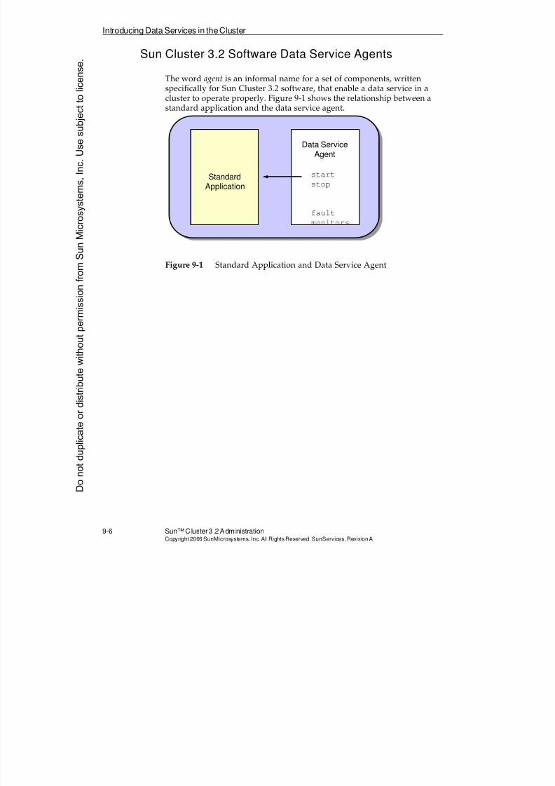
8/4/2019 Sun Cluster 3.2 Administration VC-ES-345
http://slidepdf.com/reader/full/sun-cluster-32-administration-vc-es-345 410/585
Introducing Data Services in theCluster
9-6 Sun™Cluster 3 .2AdministrationCopyright2006 SunMicrosystems, Inc. AllRights Reserved.SunServices,RevisionA
Sun Cluster 3.2 Software Data Service Agents
The word agent is an informal name for a set of components, writtenspecifically for Sun Cluster 3.2 software, that enable a data service in acluster to operate properly. Figure 9-1 shows the relationship between a
standard application and the data service agent.
Figure 9-1 Standard Application and Data Service Agent
StandardApplication
Data ServiceAgent
start
stop
faultmonitors
Donotduplicate
ordistributewithoutpermissionfrom SunMicrosystems,Inc.Usesubject
tolicense.
8/4/2019 Sun Cluster 3.2 Administration VC-ES-345
http://slidepdf.com/reader/full/sun-cluster-32-administration-vc-es-345 411/585
Reviewing Components of a Data Service Agent
Introducing Data Services, Resource Groups, and HA-NFS 9-7Copyright2006 SunMicrosystems, Inc. AllRightsReserved. SunServices,RevisionA
Reviewing Components of a Data Service Agent
Typical components of a data service agent include the following:
q Methods to start and stop the service in the cluster
q Fault monitors for the service
q Methods to start and stop the fault monitoring
q Methods to validate configuration of the service in the cluster
q A registration information file that allows the Sun Cluster softwareto store all the information about the methods into the CCR
You then only need to reference a resource type to refer to all thecomponents of the agent.
Sun Cluster software provides an API that can be called from shellprograms, and an API that can be called from C or C++ programs. Most ofthe program components of data service methods that are supported bySun products are actually compiled C and C++ programs.
Fault Monitor Components
Fault monitoring components specific to data services in Sun Cluster 3.2software are run on the local node only. This is the same node that isrunning the data service. Fault monitoring components are intended to
detect application failure and can suggest either application restarts orfailovers in the cluster. Fault monitors run only on the same nodesrunning the applications
While the actual capabilities of these fault monitors is application-specificand often poorly documented, the general strategy for fault monitors inthe Sun Cluster 3.2 environment is to monitor the health of the following:
q The daemons, by placing them under control of the process monitoring facility (rpc.pmfd). This facility calls action scripts if data servicedaemons stop unexpectedly.
q The service, by using client commands.
Note – Data service fault monitors do not need to monitor the health ofthe public network itself because this is already done by the combinationof in.mpathd and pnmd, as described in Module 8, “Managing the PublicNetwork With IPMP.”
8/4/2019 Sun Cluster 3.2 Administration VC-ES-345
http://slidepdf.com/reader/full/sun-cluster-32-administration-vc-es-345 412/585
Introducing DataService Packaging, Installation, and Registration
9-8 Sun™Cluster 3 .2AdministrationCopyright2006 SunMicrosystems, Inc. AllRights Reserved.SunServices,RevisionA
Introducing Data Service Packaging, Installation, andRegistration
Agent packages released along with Sun Cluster are part of the Java™ ES
medium. You can install them using the Java ES installer at the same timethat you install the Sun Cluster framework, you can invoke the Java ESinstaller at a later time to install them, or you can just use the pkgadd
command.
Some agents are supplied with the application software, rather than withthe cluster software.
If you intend to run certain clustered applications only in Solaris 10 non-global zones, you might install the agents only in these non-global zones.Alternatively, you might choose to install the agents always in the global
zone, without the -Goption, and have them automatically propagate to allexisting and future non-global zones.
Data Service Packages and Resource Types
Each data service agent encapsulates all the information about the agentas a resource type.
When this resource type is registered with the cluster software, you do not
need to know the location or names of the components of the agent. Youonly need to reference an application instance’s resource type todetermine all the correct information about methods and fault monitorsfor that component.
Note – The package that you add by using the pkgadd command to installan agent, and the corresponding resource type might have differentnames. For example, when you install the SUNWschtt package, a resourcetype called SUNW.iws becomes available.
Donotduplicate
ordistributewithoutpermissionfrom SunMicrosystems,Inc.Usesubject
tolicense.
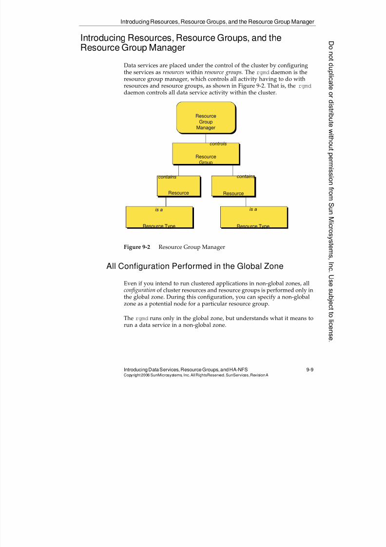
8/4/2019 Sun Cluster 3.2 Administration VC-ES-345
http://slidepdf.com/reader/full/sun-cluster-32-administration-vc-es-345 413/585
IntroducingResources, Resource Groups, and the Resource Group Manager
Introducing Data Services, Resource Groups, and HA-NFS 9-9Copyright2006 SunMicrosystems, Inc. AllRightsReserved. SunServices,RevisionA
Introducing Resources, Resource Groups, and theResource Group Manager
Data services are placed under the control of the cluster by configuring
the services as resources within resource groups. The rgmd daemon is theresource group manager, which controls all activity having to do withresources and resource groups, as shown in Figure 9-2. That is, the rgmd
daemon controls all data service activity within the cluster.
Figure 9-2 Resource Group Manager
All Configuration Performed in the Global Zone
Even if you intend to run clustered applications in non-global zones, allconfiguration of cluster resources and resource groups is performed only in
the global zone. During this configuration, you can specify a non-globalzone as a potential node for a particular resource group.
The rgmd runs only in the global zone, but understands what it means torun a data service in a non-global zone.
Resource
GroupManager
Resource
Group
Resource Resource
Resource Type Resource Type
controls
contains contains
is a is a
8/4/2019 Sun Cluster 3.2 Administration VC-ES-345
http://slidepdf.com/reader/full/sun-cluster-32-administration-vc-es-345 414/585
Introducing Resources, Resource Groups, and the Resource Group Manager
9-10 Sun™ Cluster 3.2 AdministrationCopyright2006 SunMicrosystems, Inc. AllRights Reserved.SunServices,RevisionA
Resources
In the context of clusters, the word resource refers to any element abovethe layer of the cluster framework that can be turned on or off, and can bemonitored in the cluster.
The most obvious example of a resource is an instance of a running dataservice. For example, an Apache web server, with a single httpd.conf
file, counts as one resource.
Each resource is an instance of a specific type. For example, the type forApache web server is SUNW.apache.
Other types of resources represent IP addresses and storage that arerequired by the cluster.
A particular resource is identified by the following:
q Its type, though the type is not unique for each instance
q A unique name, which is used as input and output within utilities
q A set of properties, which are parameters that define a particularresource
You can configure multiple resources of the same type in the cluster, eitherin the same or different resource groups.
For example, you might want to run two failover Apache web serverapplication services that reside, by default, on different nodes in thecluster, but could still fail over to the same node if there were only onenode available. In this case, you have two resources, both of typeSUNW.apache, in two different resource groups.
Resource Groups
Resource groups are collections of resources. Resource groups are either
failover or scalable.
Donotduplicate
ordistributewithoutpermissionfrom SunMicrosystems,Inc.Usesubject
tolicense.
8/4/2019 Sun Cluster 3.2 Administration VC-ES-345
http://slidepdf.com/reader/full/sun-cluster-32-administration-vc-es-345 415/585
IntroducingResources, Resource Groups, and the Resource Group Manager
Introducing Data Services, ResourceGroups, and HA-NFS 9-11Copyright2006 SunMicrosystems, Inc. AllRightsReserved. SunServices,RevisionA
Failover Resource Groups
For failover applications in the cluster, the resource group becomes the unitof failover. That is, the resource group is the collection of services thatalways run together on one node of the cluster at one time, and
simultaneously fail over or switch over to another node or non-globalzone.
Scalable Resource Groups
Scalable resource groups describe the collection of services thatsimultaneously run on one or more nodes or zones.
A scalable application in a scalable resource group also refers to anapplication making use of the load-balancing services built into SunCluster software. This is described further in Module 10.
8/4/2019 Sun Cluster 3.2 Administration VC-ES-345
http://slidepdf.com/reader/full/sun-cluster-32-administration-vc-es-345 416/585
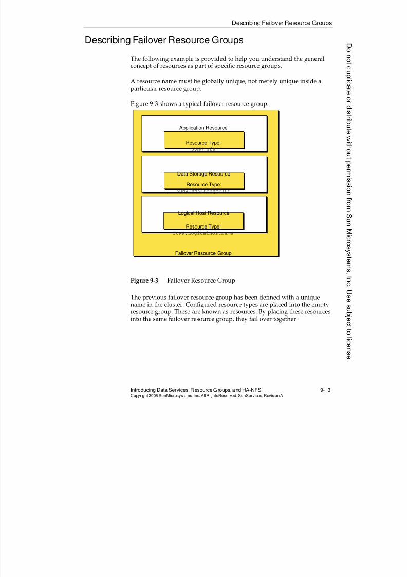
8/4/2019 Sun Cluster 3.2 Administration VC-ES-345
http://slidepdf.com/reader/full/sun-cluster-32-administration-vc-es-345 417/585
Describing Failover Resource Groups
Introducing Data Services, ResourceGroups, and HA-NFS 9-13Copyright2006 SunMicrosystems, Inc. AllRightsReserved. SunServices,RevisionA
Describing Failover Resource Groups
The following example is provided to help you understand the generalconcept of resources as part of specific resource groups.
A resource name must be globally unique, not merely unique inside aparticular resource group.
Figure 9-3 shows a typical failover resource group.
Figure 9-3 Failover Resource Group
The previous failover resource group has been defined with a uniquename in the cluster. Configured resource types are placed into the empty
resource group. These are known as resources. By placing these resourcesinto the same failover resource group, they fail over together.
Application Resource
Resource Type:
SUNW.nfs
Data Storage Resource
Resource Type:
SUNW.HAStoragePlus
Logical Host Resource
Resource Type:
SUNW.LogicalHostname
Failover Resource Group
8/4/2019 Sun Cluster 3.2 Administration VC-ES-345
http://slidepdf.com/reader/full/sun-cluster-32-administration-vc-es-345 418/585
Describing Failover Resource Groups
9-14 Sun™ Cluster 3.2 AdministrationCopyright2006 SunMicrosystems, Inc. AllRights Reserved.SunServices,RevisionA
Resources and Resource Types
Each instance of a data service under cluster control is represented by aresource within a resource group.
Resources exist only inside resource groups. There is no such thing as adisembodied resource that is not a member of a resource group.
Each resource has a resource type that describes the type of resource it is(for example, SUNW.nfs for an NFS resource).
At least one defined resource type exists for each supported service in thecluster. Some applications that are typically considered to be a singleentity, such as an instance of the ORACLE database, actually require twodifferent resources with different types: the ORACLE server and the
ORACLE listener.
In addition to resource types that relate to data services, a few otherspecial resource types relate to IP addresses and storage. These resourcetypes are described in ‘‘Using Special Resource Types’’ on page 9-15.
Resource Type Versioning
Sun Cluster 3.2 software gives you the ability to use different versions ofresource types. For example, old and new versions of data service agentscan co-exist as separate types. Individual resources of an original resourcetype can be upgraded to a new type on a resource-by-resource basis.
Officially, the version number is appended to the resource type name. Forexample, the official name of the NFS resource type is SUNW.nfs:3.2.
When using a resource type name, the version suffix can be dropped ifthere is no ambiguity. For that matter, the vendor prefix can also bedropped. So, for example, when you initially install Sun Cluster 3.2software, all of the following names can be used to refer to the nfs
resource type:q SUNW.nfs:3.2
q SUNW.nfs
q nfs:3.2
q nfs
Donotduplicate
ordistributewithoutpermissionfrom SunMicrosystems,Inc.Usesubject
tolicense.
8/4/2019 Sun Cluster 3.2 Administration VC-ES-345
http://slidepdf.com/reader/full/sun-cluster-32-administration-vc-es-345 419/585
Using Special ResourceTypes
Introducing Data Services, ResourceGroups, and HA-NFS 9-15Copyright2006 SunMicrosystems, Inc. AllRightsReserved. SunServices,RevisionA
Using Special Resource Types
The following sections describe special resources that you can include inresource groups to complete the capability of those groups.
The SUNW.LogicalHostnameResource Type
Resources of type SUNW.LogicalHostname represent one or more IPaddresses on a particular subnet that will be the logical IP addresses forservices in that resource group.
That is, each IP address described by a SUNW.LogicalHostname resourcemigrates from node to node, along with the services for that group. If thegroup is mastered by a non-global zone rather than a physical node, the
IP address is automatically placed in the appropriate zone. The client usesthese IP addresses to access the services in the cluster.
A large part of what makes cluster failover relatively transparent to theclient is that IP addresses migrate along with services of the group. Theclient always uses the same logical IP address to contact a particularinstance of a data service, regardless of which physical node or zone isactually running the service.
The SUNW.SharedAddressResource Type
Resources of type SUNW.SharedAddress represent a special type of IPaddress that is required by scalable services. This IP address is configuredon the public net of only one node or zone with failover capability, butprovides a load-balanced IP address that supports scalable applicationsthat run on multiple nodes or zones simultaneously. This subject isdescribed in greater detail in Module 10, “Configuring Scalable Servicesand Advanced Resource Group Relationships.”
8/4/2019 Sun Cluster 3.2 Administration VC-ES-345
http://slidepdf.com/reader/full/sun-cluster-32-administration-vc-es-345 420/585
Using Special Resource Types
9-16 Sun™ Cluster 3.2 AdministrationCopyright2006 SunMicrosystems, Inc. AllRights Reserved.SunServices,RevisionA
The SUNW.HAStoragePlusResource Type
The SUNW.HAStoragePlus resource type manages the following types ofstorage:
q Global raw devicesq Global file systems
q Traditional (non-ZFS) failover file systems
q Failover ZFS zpools, including all file systems within
Global Raw Devices and Global File Systems
Global device and file system management, including failover from afailed node, are part of the Sun Cluster software framework. So it might
seem redundant to provide a resource type that also manages globaldevices and file systems.
In fact, managing global storage with a SUNW.HAStoragePlus resourceis optional, but serves the following useful purposes:
q You use the START method of SUNW.HAStoragePlus to check if theglobal devices or file systems in question are accessible from thenode where the resource group is going online.
q You almost always use the Resource_dependencies standardproperty to place a dependency so that the real application resources
depend on the SUNW.HAStoragePlus resource. In this way, theresource group manager does not try to start services if the storagethe services depend on is not available.
q You can optionally still set the AffinityOn resource property toTrue, so that the SUNW.HAStoragePlus resource type attempts co-location of resource groups and device groups on the same node,thus enhancing the performance of disk-intensive data services.
Failover File Systems
You must configure a SUNW.HAStoragePlus to manage a failover filesystem. It is the resource methods that provide the failover for the filesystem.
A failover file system must fail over to a node as the service fails over, butcan fail over only to nodes physically connected to the storage.
Donotduplicate
ordistributewithoutpermissionfrom SunMicrosystems,Inc.Usesubject
tolicense.
8/4/2019 Sun Cluster 3.2 Administration VC-ES-345
http://slidepdf.com/reader/full/sun-cluster-32-administration-vc-es-345 421/585
Using Special ResourceTypes
Introducing Data Services, ResourceGroups, and HA-NFS 9-17Copyright2006 SunMicrosystems, Inc. AllRightsReserved. SunServices,RevisionA
The configuration of a global or failover file system look very similar. Bothuse the FilesystemMountPointsproperty to point to the file system orfile systems in question. The SUNW.HAStoragePlusmethods distinguish between global and failover file systems by the /etc/vfstab entry.
Guidelines for Using Global and Failover File Systems
These are some general guidelines about how to choose between globaland failover file systems.
When to Use a Global File System
Use a global file system if you want to support any of the following:
q A scalable service
q A failover service that must fail over to a node not physicallyconnected to the storage
q A single file system that contains data for different failover servicesthat may be running on different nodes.
q Access to the data from a node that is not currently running theservice
If your storage is physically connected to all possible nodes for theresource group containing the HAStoragePlus, you can still use
AffinityOn=true to migrate the underlying ownership storage alongwith the service, if that makes sense, as a performance benefit.
When to Use a Failover File System
Use a failover file system if all of the following are true:
q The file system is for a failover service only.
q The Nodelist for the resource group contains only nodes that arephysically connected to the storage; that is, if the Nodelist for the
resource groups is the same as the Nodelist for the device group.q Only services in a single resource group are using the file system.
If these conditions are true, a failover file system provides a higher levelof performance than a global file system, especially for services that arefile system intensive.
8/4/2019 Sun Cluster 3.2 Administration VC-ES-345
http://slidepdf.com/reader/full/sun-cluster-32-administration-vc-es-345 422/585
Using Special Resource Types
9-18 Sun™ Cluster 3.2 AdministrationCopyright2006 SunMicrosystems, Inc. AllRights Reserved.SunServices,RevisionA
HAStoragePlusResources in Zones
When a traditional (non-ZFS) file system that is controlled by anHAStoragePlus resource is contained in a resource group that is mastered by a non-global zone, the file system is still always mounted in the
appropriate global zone, and then made available to the non-global zonethrough a loopback mount.
HAStoragePlus and ZFS
The same HAStoragePlus resource that provides failover of traditionalfilesystems can also provide ZFS failover. For ZFS, an HAStoragePlus
instance represents one or more zpools and all the file systems within.
To manage failover of ZFS filesystems within the cluster, all you have todo is configure an HAStoragePlus instance with the value of the Zpools
property indicating one or more pools that should fail over. You do notneed to configure any /etc/vfstab entries whatsoever. All of the ZFSmount information is self-contained in the zpool configuration database.
Note – A single HAStoragePlus instance can refer to multiple traditional(non-ZFS) filesystems, or multiple ZFS zpools, but not both. When youuse the Zpools property the values of the properties for traditionalfilesystems (FilesystemMountPoints and AffinityOn) are ignored.
ZFS technology is zone-aware, and ZFS zpools that are configured into anon-global zone via HAStoragePlus are only exposed in that zone.
Generic Data Service
The Generic Data Service (GDS) is a resource type for making simpleapplications highly available or scalable using the resource typeSUNW.gds by plugging them into the Sun Cluster RGM framework. The
GDS composes a fully functional Sun Cluster Resource Type completewith callback methods and a Resource Type Registration file.
Basically, the concept is that many different applications can share thesame resource type. All you have to do is have a resource type where whatis being launched is not implied by the resource type itself. Instead, what isbeing launched, how to probe this application, and how to stop this applicationare just properties that can be set differently for each instance ofSUNW.gds.
Donotduplicate
ordistributewithoutpermissionfrom SunMicrosystems,Inc.Usesubject
tolicense.
8/4/2019 Sun Cluster 3.2 Administration VC-ES-345
http://slidepdf.com/reader/full/sun-cluster-32-administration-vc-es-345 423/585
Using Special ResourceTypes
Introducing Data Services, ResourceGroups, and HA-NFS 9-19Copyright2006 SunMicrosystems, Inc. AllRightsReserved. SunServices,RevisionA
Many Sun-supported data services (for example, DHCP, Samba, andmany more) do not actually supply new resource types. Rather, theysupply configuration scripts that configure resources to represent theapplications as instances of SUNW.gds.
In the lab exercises for this module, you will get an opportunity to use aninstance of the SUNW.gds type to put your own customized applicationunder control of the Sun Cluster software.
8/4/2019 Sun Cluster 3.2 Administration VC-ES-345
http://slidepdf.com/reader/full/sun-cluster-32-administration-vc-es-345 424/585
Understanding ResourceDependencies and Resource Group Dependencies
9-20 Sun™ Cluster 3.2 AdministrationCopyright2006 SunMicrosystems, Inc. AllRights Reserved.SunServices,RevisionA
Understanding Resource Dependencies and ResourceGroup Dependencies
You can declare dependency relationships between resources.
Relationships between individual resources can be between resources inthe same or different resource groups. You can also configure groupdependencies that take into account only the state of a group rather thanthe state of its resources.
There are three levels of resource dependencies.
Regular Resource Dependencies
If Resource A depends on resource B , then:
q Resource B must be started first (without the dependency, RGM mighthave been able to start them in parallel).
q Resource A must be stopped first (without the dependency, RGMmight have been able to stop them in parallel).
q The rgmd daemon will not try to start resource A if resource B fails togo online, and will not try to stop resource B if resource A fails to bestopped.
q You are allowed to specifically, manually, disable resource B, even ifresource A is still running. This is somewhat counterintuitive, but
because you are explicitly issuing the command (clrs disable) todisable the dependee, you can do it.
q If A and B are in different resource groups, you are not allowed to putthe resource group containing B offline if resource A is still online.
Weak Dependencies (Weaker Than Regular Dependencies)
If resource A has a weak dependency on resource B , rgmd preserves the orderof the stops and starts as if it were a real dependency, but does not reallyenforce the dependency in other ways. If B fails to start, the rgmd will still
try to start A. You can manually disable either resource or its group freely.
Donotduplicate
ordistributewithoutpermissionfrom SunMicrosystems,Inc.Usesubject
tolicense.
8/4/2019 Sun Cluster 3.2 Administration VC-ES-345
http://slidepdf.com/reader/full/sun-cluster-32-administration-vc-es-345 425/585
Understanding Resource Dependencies and Resource Group Dependencies
Introducing Data Services, ResourceGroups, and HA-NFS 9-21Copyright2006 SunMicrosystems, Inc. AllRightsReserved. SunServices,RevisionA
Restart Dependencies (Stronger Than Regular Dependencies)
Restart dependencies have all the attributes of regular dependencies, withthe additional attribute that if the RGM is told to restart resource B, or isinformed that some agent did the restart of resource B itself, the RGM will
automatically restart resource A.
Similar to the case of regular dependencies, you are allowed to manually,specifically disable the dependee, resource B, while leaving resource Arunning. However, when you manually reenable resource B, the restartdependency begins, and the RGM restarts resource A
Offline-Restart Dependencies (Slight Variation of Restart
Dependencies)
In this slight variation, when RGM is informed that the dependee(resource B) is offline, or when it is put explicitly offline, the RGM issues arestart on resource A. Resource A explicitly depends on resource B;therefore, resource A’s start will be blocked until B actually restarts.
Resource Group Dependencies
Resource group dependencies imply an ordering relationship betweentwo groups: If resource group G has a group dependency on resourcegroup H, group G cannot be brought online unless group H is online.Group H cannot be brought offline unless group G is offline. This type ofdependency considers the state of the group only rather than theresources inside it.
Note – Resource group dependencies are somewhat limited. They areenforced between groups running on different nodes when you manuallytry to start or stop resource groups in the wrong dependency order,regardless of which nodes the groups are mastered.
They consider only the group state and not individual resource state;therefore, resource group dependencies are made obsolete by the variousflavors of resource dependencies, now that they can be between resourcesin different groups.
8/4/2019 Sun Cluster 3.2 Administration VC-ES-345
http://slidepdf.com/reader/full/sun-cluster-32-administration-vc-es-345 426/585
Configuring Resource and ResourceGroups ThroughProperties
9-22 Sun™ Cluster 3.2 AdministrationCopyright2006 SunMicrosystems, Inc. AllRights Reserved.SunServices,RevisionA
Configuring Resource and Resource Groups ThroughProperties
You configure specific resources within the cluster by defining values for
resource properties and resource group properties. Properties consist of aset of name=value pairs.
These properties are used by the data service agent and by rgmd. There isno way they can be accessed directly by the application software itself, because it is cluster-unaware software.
Some properties are essential for running the service in the cluster. Scriptsspecifically used to run the service in the cluster can read these propertyvalues and use them to locate configuration files, or can use them to passcommand-line parameters to the actual services.
Other properties are essential only for data service fault monitoring.Misconfiguring these properties might leave the service running fine, butcause fault monitoring to fail.
Each resource can literally have dozens of properties. Fortunately, manyimportant properties for particular types of resources are automaticallyprovided with reasonable default values. Therefore, most administratorsof Sun Cluster software environments never need to deal with theproperties.
Standard Resource Properties
The names of standard resource properties can be used with any type ofresource.
You can access a full list of standard resource properties and their generalmeanings by typing:
# man r_properties
Of the dozens of properties listed, only a handful are critical for aparticular resource type. Other properties can be ignored, or can havedefault values that are unlikely to be changed.
Donotduplicate
ordistributewithoutpermissionfrom SunMicrosystems,Inc.Usesubject
tolicense.
8/4/2019 Sun Cluster 3.2 Administration VC-ES-345
http://slidepdf.com/reader/full/sun-cluster-32-administration-vc-es-345 427/585
Configuring Resource and Resource Groups Through Properties
Introducing Data Services, ResourceGroups, and HA-NFS 9-23Copyright2006 SunMicrosystems, Inc. AllRightsReserved. SunServices,RevisionA
Some Significant Standard Resource Properties
The following properties are standard resource properties; that is, theycan have meaningful values for many different types of resources.
The Resource_dependenciesProperty
Resource dependencies, which imply ordering, are configured usingstandard properties.
Resource_dependencies=nfs-stor
The Resource_dependencies_weakProperty
To set up a weak dependency, so that resource A has a weak dependency
on resource B , set the Resource_dependencies_weakproperty onresource A. (Recall that this implies an ordering, but not a realdependency.)
Resource_dependencies_weak=resB
The Resource_dependencies_restartandResource_dependencies_offline_restartProperties
To set the two kinds of restart dependencies , set theResource_dependencies_restartor
Resource_dependencies_offline_restartproperty on resource A.Resource_dependencies_restart=resB
Resource_dependencies_offline_restart=resB
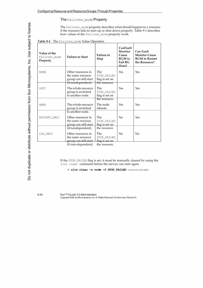
8/4/2019 Sun Cluster 3.2 Administration VC-ES-345
http://slidepdf.com/reader/full/sun-cluster-32-administration-vc-es-345 428/585
Configuring Resource and ResourceGroups ThroughProperties
9-24 Sun™ Cluster 3.2 AdministrationCopyright2006 SunMicrosystems, Inc. AllRights Reserved.SunServices,RevisionA
The Failover_modeProperty
The Failover_modeproperty describes what should happen to a resourceif the resource fails to start up or shut down properly. Table 9-1 describeshow values of the Failover_mode property work.
If the STOP_FAILED flag is set, it must be manually cleared by using theclrs clear command before the service can start again.
# clrs clear -n node -f STOP_FAILED resourcename
Table 9-1 The Failover_modeValue Operation
Value of theFailover_mode
PropertyFailure to Start Failure to
Stop
CanFaultMonitorCauseRGM toFail RGOver?
Can FaultMonitor CauseRGM to Restartthe Resource?
NONE Other resources inthe same resourcegroup can still start(if nondependent).
TheSTOP_FAILED
flag is set onthe resource.
Yes Yes
SOFT The whole resourcegroup is switchedto another node.
TheSTOP_FAILED
flag is set onthe resource.
Yes Yes
HARD The whole resourcegroup is switchedto another node.
The nodereboots.
Yes Yes
RESTART_ONLY Other resources inthe same resourcegroup can still start(if nondependent).
TheSTOP_FAILED
flag is set onthe resource.
No Yes
LOG_ONLY Other resources inthe same resourcegroup can still start(if non-dependent).
TheSTOP_FAILED
flag is set onthe resource.
No No
Donotduplicate
ordistributewithoutpermissionfrom SunMicrosystems,Inc.Usesubject
tolicense.
8/4/2019 Sun Cluster 3.2 Administration VC-ES-345
http://slidepdf.com/reader/full/sun-cluster-32-administration-vc-es-345 429/585
Configuring Resource and Resource Groups Through Properties
Introducing Data Services, ResourceGroups, and HA-NFS 9-25Copyright2006 SunMicrosystems, Inc. AllRightsReserved. SunServices,RevisionA
Extension Properties
Names of extension properties are specific to resources of a particulartype. You can get information about extension properties from the manpage for a specific resource type. For example:
# man SUNW.apache
# man SUNW.HAStoragePlus
If you are setting up the Apache web server, for example, you must createa value for the Bin_dirproperty, which points to the directory containingthe apachectl script that you want to use to start the web server.
The HAStoragePlus type has the following important extensionproperties regarding filesystems.
FilesystemMountPoints=list_of_storage_mount_pointsAffinityOn=True/False
--------------------
Zpools=list_of_zpools
Use the first of these extension properties to identify which storageresource is being described. The second extension property is a parameterthat tells the cluster framework to switch physical control of the storagegroup to the node running the service. Switching control to the node thatis running the service optimizes performance when services in a singlefailover resource group are the only services accessing the storage. The
third property (Zpools) is used only for specifying pool names for afailover ZFS resource, in which case the first two properties are not used.
Many resource types (including LDAP and DNS) have an extensionproperty called Confdir_list that points to the configuration.
Confdir_list=/global/dnsconflocation
Many have other ways of identifying their configuration and data. Thereis no hard-and-fast rule about extension properties.
Resource Group Properties
Certain properties apply to an entire resource group. You can getinformation about these properties by typing:
# man rg_properties
8/4/2019 Sun Cluster 3.2 Administration VC-ES-345
http://slidepdf.com/reader/full/sun-cluster-32-administration-vc-es-345 430/585
Configuring Resource and ResourceGroups ThroughProperties
9-26 Sun™ Cluster 3.2 AdministrationCopyright2006 SunMicrosystems, Inc. AllRights Reserved.SunServices,RevisionA
Some Significant Resource Group Properties
The following properties are associated with an entire resource group,rather than an individual resource.
The RG_dependenciesProperty
The RG_dependencies property will be set on a whole resource group todescribe its dependency on another group. If resource group A has theproperty RG_dependencies=rgB, then resource group A cannot be brought online unless resource group B is online. Resource group B must be brought online somewhere, but not necessarily on the same node.
The NodelistProperty
The Nodelist property for a resource group describes what nodes orzones the resource group can run on.
The value of this property is always an ordered list, from most preferrednode to least preferred node. A non-global zone acts as a virtual nodefrom the point of view of a resource group node list. As mentioned before,while it is not strictly the intention of the cluster zone integration feature,it is possible for the same groups’s node list to include multiple zones onthe same physical node.
The FailbackProperty
If the Failback property is TRUE (not the default), the resource groupautomatically switches back when a preferred node or zone (earlier in thenode list) joins the cluster.
The Implicit_network_dependenciesProperty
The Implicit_network_dependenciesproperty is TRUE by default. Thisproperty makes all the services in the resource group dependent on all the
LogicalHostname and SharedAddress resources. In other words, noservices can start if logical IP addresses cannot be brought online. You canset the Implicit_Network_Dependenciesproperty to FALSE if you havea service that does not depend on logical IP addresses.
Donotduplicate
ordistributewithoutpermissionfrom SunMicrosystems,Inc.Usesubject
tolicense.
8/4/2019 Sun Cluster 3.2 Administration VC-ES-345
http://slidepdf.com/reader/full/sun-cluster-32-administration-vc-es-345 431/585
Configuring Resource and Resource Groups Through Properties
Introducing Data Services, ResourceGroups, and HA-NFS 9-27Copyright2006 SunMicrosystems, Inc. AllRightsReserved. SunServices,RevisionA
The Pingpong_intervalProperty
This property controls resource group behavior in a couple of differentways:
q If a resource group fails to start twice on the same particular node or
zone (failure of START methods of same or different resources in thegroup) within the interval (expressed in seconds), then the RGMdoes not consider that node or zone a candidate for the groupfailover.
q If the fault monitor for one particular resource requests that a group befailed off a particular node or zone, and then the fault monitor forthe same resource requests another failover that would bring thegroup back to the original node or zone, the RGM rejects the secondfailover if it is within the interval.
Note – The Pingpong_intervalproperty is meant to prohibit faulty startscripts or properties and faulty fault monitors, or problem applications,from causing endless ping-ponging between nodes or zones.
The PathprefixProperty
The Pathprefix property points to a directory in a shared-storage filesystem that is used for the administrative purposes of services in theresource group.
Currently, the only data service that must have the Pathprefix propertyset is NFS, which uses the property to find its dfstab file. NFS needs thedfstab file so that it knows what it is supposed to be sharing. NFS alsouses the same arena to store file lock state information. File lock stateinformation is typically stored in the /etc directory on a stand-alone NFSserver, but it must be in the shared storage in the cluster.
An NFS resource must have its dfstab file named:
value_of_Pathprefix_for_RG/SUNW.nfs/dfstab.resource_name
When you create an NFS resource, the resource checks that thePathprefixproperty is set on its resource group, and that the dfstab fileexists.
8/4/2019 Sun Cluster 3.2 Administration VC-ES-345
http://slidepdf.com/reader/full/sun-cluster-32-administration-vc-es-345 432/585
Specifying Non-Global Zone Names in Placeof Node Names
9-28 Sun™ Cluster 3.2 AdministrationCopyright2006 SunMicrosystems, Inc. AllRights Reserved.SunServices,RevisionA
Specifying Non-Global Zone Names in Place of NodeNames
You may specify non-global zone names in the place of node names in the
following contexts:q When specifying or modifying the node list for a resource type
q When specifying or modifying the node list for a resource group
q When switching a resource group to a particular node
q When enabling or disabling a resource or resource flag on aparticular node
The commands to perform these operations are presented in the next fewsections, but there are some general rules in using zone names:
q The form nodename:zonename is used to specify a zone on aparticular node.
q You can easily give zones on different nodes the same or differentzone names. They are considered to be different virtual nodes by thecluster either way.
q The syntax -n nodename -z zonename is identical to-n nodename:zonename.
q The syntax -n node1,node2,... -z zonename
is a shorthand for-n node1:zonename,node2:zonename,...
Inother words, it is a shorthand you can choose when specifyingmultiple zones on different nodes if you happen to have chosen touse the same zone name.
Donotduplicate
ordistributewithoutpermissionfrom SunMicrosystems,Inc.Usesubject
tolicense.
8/4/2019 Sun Cluster 3.2 Administration VC-ES-345
http://slidepdf.com/reader/full/sun-cluster-32-administration-vc-es-345 433/585
Using theclresourcetype(clrt) Command
Introducing Data Services, ResourceGroups, and HA-NFS 9-29Copyright2006 SunMicrosystems, Inc. AllRightsReserved. SunServices,RevisionA
Using the clresourcetype (clrt) Command
You use clresourcetype (clrt) to register or unregister a resource type.Registering a resource type makes it known to the CCR and available to be used for new resources.
If you register a type and do not specify a node list, you are allowing thattype to be used on all nodes and non-global zones, even ones that areadded and created in the future. In other words, the default is to place norestriction on where resources of your registered type could run. Theassumption is that you will have the data service agent installed on allnodes.
If you do specify a node list, you are restricting your resource type tocertain nodes or zones. The cluster then allows you to specify only those
nodes or zones for the resource groups that contain resources of that type.The only property of a registered resource type that you can modify withthe clrt command is the node list.
Registering Resource Types
The following examples show registration of resource types. The firstexample specifies a node list of all current and future nodes. The secondexample limits the node list to only the nodes mentioned.
# clrt register SUNW.nfs# clrt register -n vincent,theo SUNW.apache
Yo Note – You can specify a zone with the syntax nodename:zonename.
8/4/2019 Sun Cluster 3.2 Administration VC-ES-345
http://slidepdf.com/reader/full/sun-cluster-32-administration-vc-es-345 434/585
Using the clresourcetype(clrt) Command
9-30 Sun™ Cluster 3.2 AdministrationCopyright2006 SunMicrosystems, Inc. AllRights Reserved.SunServices,RevisionA
Viewing Registered Resource Types
clrt list -v shows the list of registered resource types and their nodelists. clrt show can display more about a specific registered type or allregistered types:
vincent:/# clrt list -v
Resource Type Node List
------------- ---------
SUNW.LogicalHostname:2 <All>
SUNW.SharedAddress:2 <All>
SUNW.HAStoragePlus:4 <All>
SUNW.nfs:3.2 <All>
SUNW.apache:4 vincent theo
vincent:/# clrt show apache
Registered Resource Types ===
Resource Type: SUNW.apache:4
RT_description: Apache Web Server on Sun Cluster
RT_version: 4
API_version: 2
RT_basedir: /opt/SUNWscapc/bin
Single_instance: False
Proxy: False
Init_nodes: All potential masters
Installed_nodes: vincent theoFailover: False
Pkglist: SUNWscapc
RT_system: False
Global_zone: False
Note – The Failover (False) and Global_zone (False) mean that theresource type is not limited to being failover only (that is, it can be failoveror scalable) and is not limited to the global zone only.
Unregistering Types
You can unregister only unused types (for which there are no resourceinstances):
# clrt unregister nfsDonotduplicate
ordistributewithoutpermissionfrom SunMicrosystems,Inc.Usesubject
tolicense.
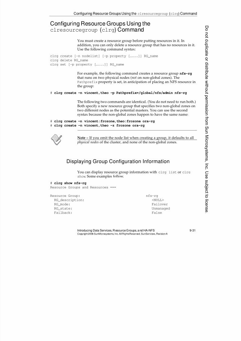
8/4/2019 Sun Cluster 3.2 Administration VC-ES-345
http://slidepdf.com/reader/full/sun-cluster-32-administration-vc-es-345 435/585
Configuring Resource Groups Using the clresourcegroup (clrg) Command
Introducing Data Services, ResourceGroups, and HA-NFS 9-31Copyright2006 SunMicrosystems, Inc. AllRightsReserved. SunServices,RevisionA
Configuring Resource Groups Using theclresourcegroup (clrg) Command
You must create a resource group before putting resources in it. In
addition, you can only delete a resource group that has no resources in it.Use the following command syntax:
clrg create [-n nodelist] [-p property […...]] RG_name
clrg delete RG_name
clrg set [-p property […...]] RG_name
For example, the following command creates a resource group nfs-rg
that runs on two physical nodes (not on non-global zones). ThePathprefix property is set, in anticipation of placing an NFS resource inthe group:
# clrg create -n vincent,theo -p Pathprefix=/global/nfs/admin nfs-rg
The following two commands are identical. (You do not need to run both.)Both specify a new resource group that specifies two non-global zones ontwo different nodes as the potential masters. You can use the secondsyntax because the non-global zones happen to have the same name:
# clrg create -n vincent:frozone,theo:frozone ora-rg
# clrg create -n vincent,theo -z frozone ora-rg
Note – If you omit the node list when creating a group, it defaults to all physical nodes of the cluster, and none of the non-global zones.
Displaying Group Configuration Information
You can display resource group information with clrg list or clrgshow. Some examples follow.
# clrg show nfs-rgResource Groups and Resources ===
Resource Group: nfs-rg
RG_description: <NULL>
RG_mode: Failover
RG_state: Unmanaged
Failback: False
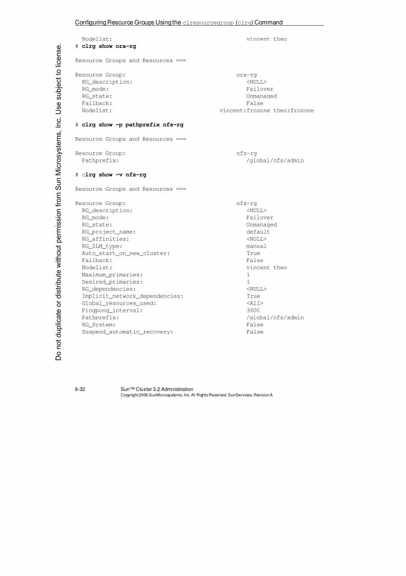
8/4/2019 Sun Cluster 3.2 Administration VC-ES-345
http://slidepdf.com/reader/full/sun-cluster-32-administration-vc-es-345 436/585
Configuring Resource Groups Using theclresourcegroup (clrg) Command
9-32 Sun™ Cluster 3.2 AdministrationCopyright2006 SunMicrosystems, Inc. AllRights Reserved.SunServices,RevisionA
Nodelist: vincent theo
# clrg show ora-rg
Resource Groups and Resources ===
Resource Group: ora-rg
RG_description: <NULL>
RG_mode: Failover
RG_state: Unmanaged
Failback: False
Nodelist: vincent:frozone theo:frozone
# clrg show -p pathprefix nfs-rg
Resource Groups and Resources ===
Resource Group: nfs-rgPathprefix: /global/nfs/admin
# clrg show -v nfs-rg
Resource Groups and Resources ===
Resource Group: nfs-rg
RG_description: <NULL>
RG_mode: Failover
RG_state: Unmanaged
RG_project_name: defaultRG_affinities: <NULL>
RG_SLM_type: manual
Auto_start_on_new_cluster: True
Failback: False
Nodelist: vincent theo
Maximum_primaries: 1
Desired_primaries: 1
RG_dependencies: <NULL>
Implicit_network_dependencies: True
Global_resources_used: <All>
Pingpong_interval: 3600Pathprefix: /global/nfs/admin
RG_System: False
Suspend_automatic_recovery: False
Donotduplicate
ordistributewithoutpermissionfrom SunMicrosystems,Inc.Usesubject
tolicense.
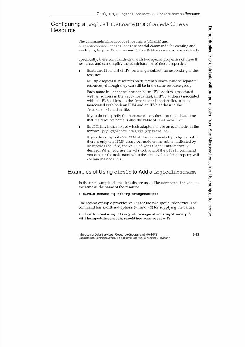
8/4/2019 Sun Cluster 3.2 Administration VC-ES-345
http://slidepdf.com/reader/full/sun-cluster-32-administration-vc-es-345 437/585
Configuring a LogicalHostnameor a SharedAddressResource
Introducing Data Services, ResourceGroups, and HA-NFS 9-33Copyright2006 SunMicrosystems, Inc. AllRightsReserved. SunServices,RevisionA
Configuring a LogicalHostnameor a SharedAddressResource
The commands clreslogicalhostname (clrslh) and
clressharedaddress (clrssa) are special commands for creating andmodifying LogicalHostname and SharedAddress resources, respectively.
Specifically, these commands deal with two special properties of these IPresources and can simplify the administration of these properties:
q Hostnamelist: List of IPs (on a single subnet) corresponding to thisresource
Multiple logical IP resources on different subnets must be separateresources, although they can still be in the same resource group.
Each name inHostnamelist
can be an IPV4 address (associatedwith an address in the /etc/hostsfile), an IPV6 address (associatedwith an IPV6 address in the /etc/inet/ipnodes file), or both(associated with both an IPV4 and an IPV6 address in the/etc/inet/ipnodes) file.
If you do not specify the Hostnamelist, these commands assumethat the resource name is also the value of Hostnamelist.
q NetIfList: Indication of which adapters to use on each node, in theformat: ipmp_grp@node_id ,ipmp_grp@node_id,..
If you do not specify NetIfList, the commands try to figure out if
there is only one IPMP group per node on the subnet indicated byHostnamelist. If so, the value of NetIfList is automaticallyderived. When you use the -N shorthand of the clrslh commandyou can use the node names, but the actual value of the property willcontain the node id’s.
Examples of Using clrslh to Add a LogicalHostname
In the first example, all the defaults are used. The HostnameList value is
the same as the name of the resource.# clrslh create -g nfs-rg orangecat-nfs
The second example provides values for the two special properties. Thecommand has shorthand options (-h and -N) for supplying the values:
# clrslh create -g nfs-rg -h orangecat-nfs,myother-ip \
-N therapy@vincent,therapy@theo orangecat-nfs
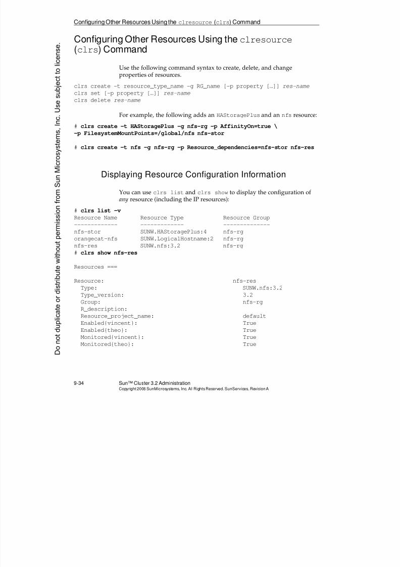
8/4/2019 Sun Cluster 3.2 Administration VC-ES-345
http://slidepdf.com/reader/full/sun-cluster-32-administration-vc-es-345 438/585
Configuring Other Resources Using the clresource (clrs) Command
9-34 Sun™ Cluster 3.2 AdministrationCopyright2006 SunMicrosystems, Inc. AllRights Reserved.SunServices,RevisionA
Configuring Other Resources Using the clresource(clrs) Command
Use the following command syntax to create, delete, and change
properties of resources.clrs create -t resource_type_name -g RG_name [-p property […]] res-name
clrs set [-p property […]] res-name
clrs delete res-name
For example, the following adds an HAStoragePlus and an nfs resource:
# clrs create -t HAStoragePlus -g nfs-rg -p AffinityOn=true \
-p FilesystemMountPoints=/global/nfs nfs-stor
# clrs create -t nfs -g nfs-rg -p Resource_dependencies=nfs-stor nfs-res
Displaying Resource Configuration Information
You can use clrs list and clrs show to display the configuration ofany resource (including the IP resources):
# clrs list -v
Resource Name Resource Type Resource Group
------------- ------------- --------------
nfs-stor SUNW.HAStoragePlus:4 nfs-rgorangecat-nfs SUNW.LogicalHostname:2 nfs-rg
nfs-res SUNW.nfs:3.2 nfs-rg
# clrs show nfs-res
Resources ===
Resource: nfs-res
Type: SUNW.nfs:3.2
Type_version: 3.2
Group: nfs-rg
R_description:
Resource_project_name: default
Enabled{vincent}: True
Enabled{theo}: True
Monitored{vincent}: True
Monitored{theo}: True
Donotduplicate
ordistributewithoutpermissionfrom SunMicrosystems,Inc.Usesubject
tolicense.
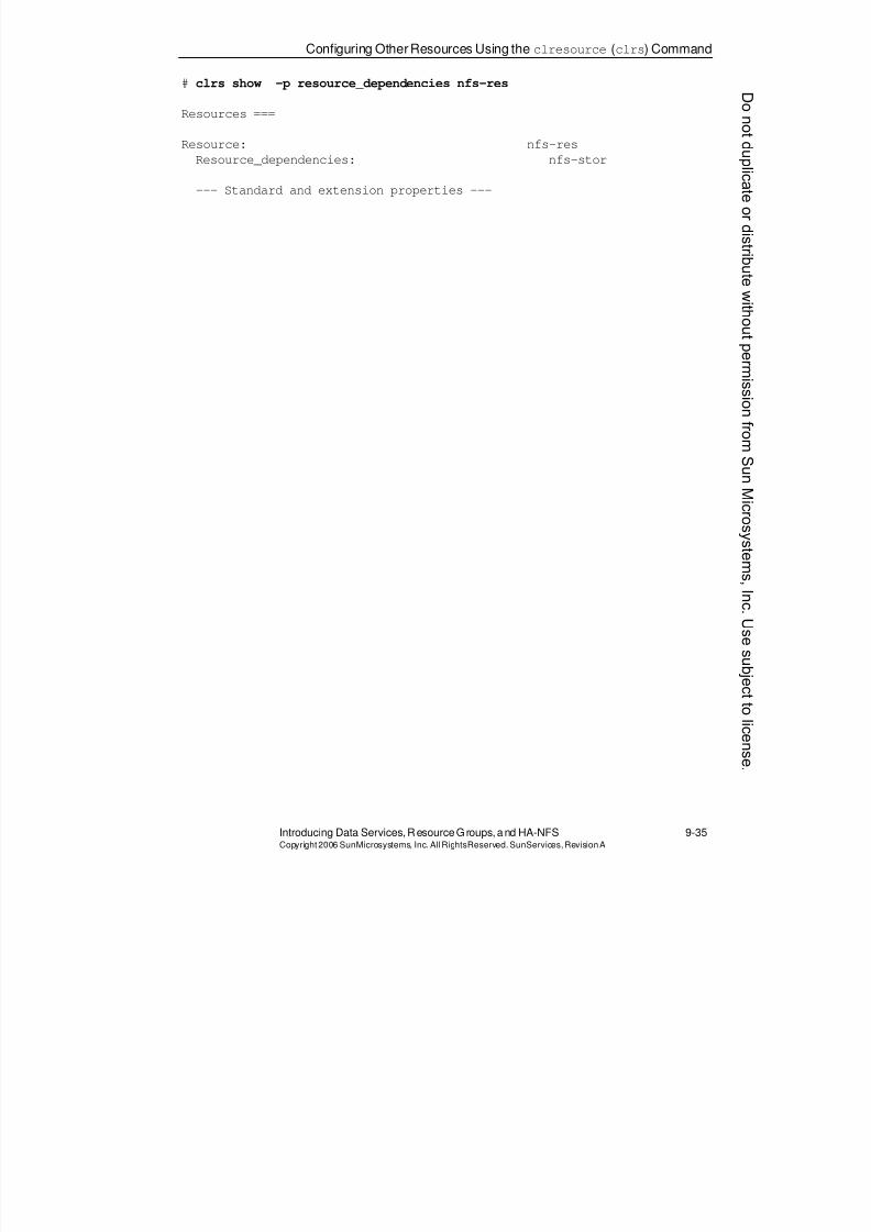
8/4/2019 Sun Cluster 3.2 Administration VC-ES-345
http://slidepdf.com/reader/full/sun-cluster-32-administration-vc-es-345 439/585
Configuring OtherResources Using theclresource (clrs) Command
Introducing Data Services, ResourceGroups, and HA-NFS 9-35Copyright2006 SunMicrosystems, Inc. AllRightsReserved. SunServices,RevisionA
# clrs show -p resource_dependencies nfs-res
Resources ===
Resource: nfs-res
Resource_dependencies: nfs-stor
--- Standard and extension properties ---
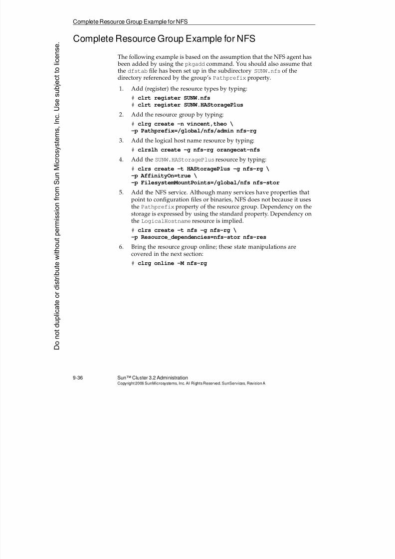
8/4/2019 Sun Cluster 3.2 Administration VC-ES-345
http://slidepdf.com/reader/full/sun-cluster-32-administration-vc-es-345 440/585
Complete Resource Group Example for NFS
9-36 Sun™ Cluster 3.2 AdministrationCopyright2006 SunMicrosystems, Inc. AllRights Reserved.SunServices,RevisionA
Complete Resource Group Example for NFS
The following example is based on the assumption that the NFS agent has been added by using the pkgadd command. You should also assume thatthe dfstab file has been set up in the subdirectory SUNW.nfs of thedirectory referenced by the group’s Pathprefix property.
1. Add (register) the resource types by typing:
# clrt register SUNW.nfs
# clrt register SUNW.HAStoragePlus
2. Add the resource group by typing:
# clrg create -n vincent,theo \
-p Pathprefix=/global/nfs/admin nfs-rg
3. Add the logical host name resource by typing:
# clrslh create -g nfs-rg orangecat-nfs4. Add the SUNW.HAStoragePlus resource by typing:
# clrs create -t HAStoragePlus -g nfs-rg \
-p AffinityOn=true \
-p FilesystemMountPoints=/global/nfs nfs-stor
5. Add the NFS service. Although many services have properties thatpoint to configuration files or binaries, NFS does not because it usesthe Pathprefix property of the resource group. Dependency on thestorage is expressed by using the standard property. Dependency onthe LogicalHostname resource is implied.
# clrs create -t nfs -g nfs-rg \
-p Resource_dependencies=nfs-stor nfs-res
6. Bring the resource group online; these state manipulations arecovered in the next section:
# clrg online -M nfs-rg
Donotduplicate
ordistributewithoutpermissionfrom SunMicrosystems,Inc.Usesubject
tolicense.
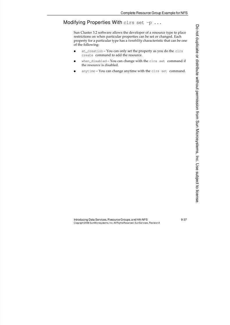
8/4/2019 Sun Cluster 3.2 Administration VC-ES-345
http://slidepdf.com/reader/full/sun-cluster-32-administration-vc-es-345 441/585
Complete Resource Group Example for NFS
Introducing Data Services, ResourceGroups, and HA-NFS 9-37Copyright2006 SunMicrosystems, Inc. AllRightsReserved. SunServices,RevisionA
Modifying Properties With clrs set -p ...
Sun Cluster 3.2 software allows the developer of a resource type to placerestrictions on when particular properties can be set or changed. Eachproperty for a particular type has a tunability characteristic that can be one
of the following:
q at_creation – You can only set the property as you do the clrs
create command to add the resource.
q when_disabled – You can change with the clrs set command ifthe resource is disabled.
q anytime – You can change anytime with the clrs set command.
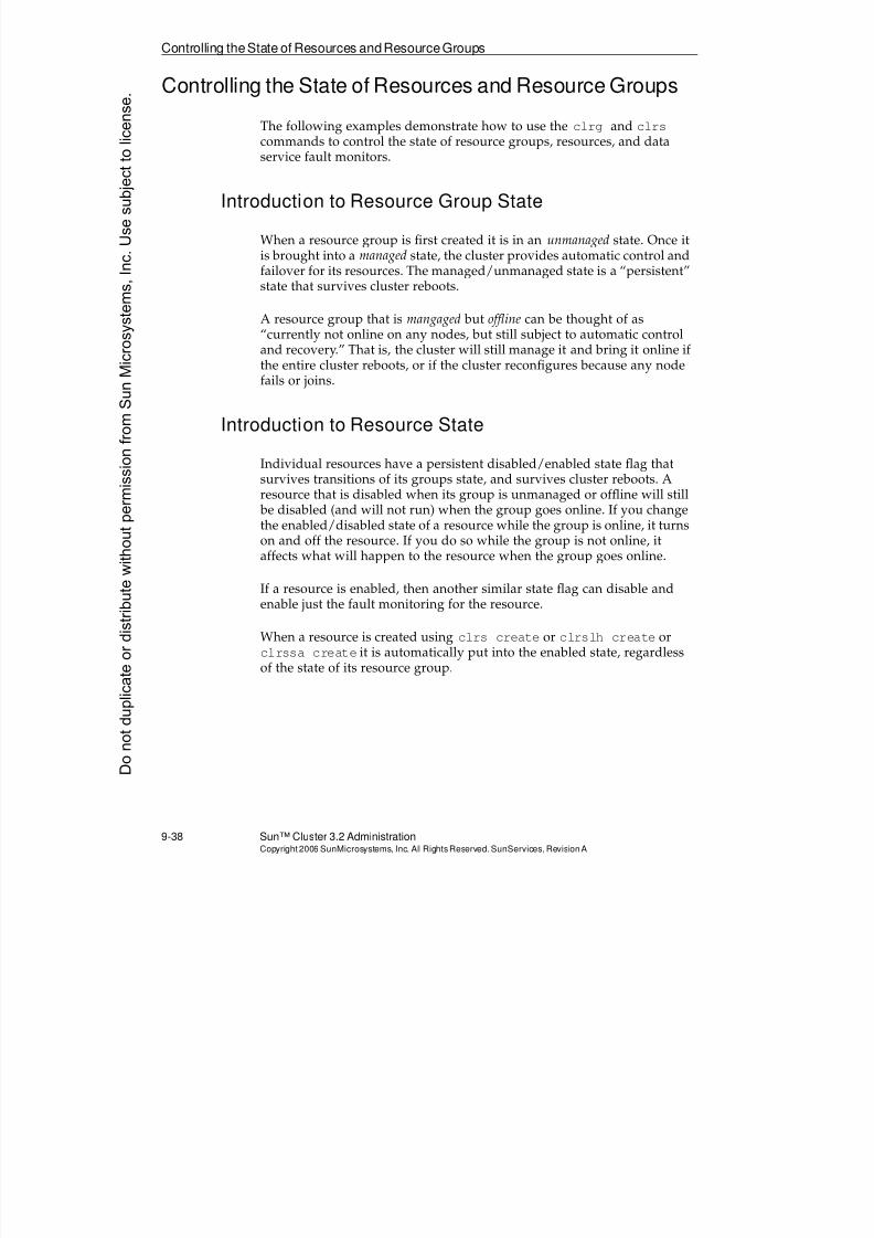
8/4/2019 Sun Cluster 3.2 Administration VC-ES-345
http://slidepdf.com/reader/full/sun-cluster-32-administration-vc-es-345 442/585
Controlling theState of Resources andResourceGroups
9-38 Sun™ Cluster 3.2 AdministrationCopyright2006 SunMicrosystems, Inc. AllRights Reserved.SunServices,RevisionA
Controlling the State of Resources and Resource Groups
The following examples demonstrate how to use the clrg and clrs
commands to control the state of resource groups, resources, and dataservice fault monitors.
Introduction to Resource Group State
When a resource group is first created it is in an unmanaged state. Once itis brought into a managed state, the cluster provides automatic control andfailover for its resources. The managed/unmanaged state is a “persistent”state that survives cluster reboots.
A resource group that is mangaged but offline can be thought of as
“currently not online on any nodes, but still subject to automatic controland recovery.” That is, the cluster will still manage it and bring it online ifthe entire cluster reboots, or if the cluster reconfigures because any nodefails or joins.
Introduction to Resource State
Individual resources have a persistent disabled/enabled state flag thatsurvives transitions of its groups state, and survives cluster reboots. Aresource that is disabled when its group is unmanaged or offline will still be disabled (and will not run) when the group goes online. If you changethe enabled/disabled state of a resource while the group is online, it turnson and off the resource. If you do so while the group is not online, itaffects what will happen to the resource when the group goes online.
If a resource is enabled, then another similar state flag can disable andenable just the fault monitoring for the resource.
When a resource is created using clrs create or clrslh create orclrssa create it is automatically put into the enabled state, regardless
of the state of its resource group.
Donotduplicate
ordistributewithoutpermissionfrom SunMicrosystems,Inc.Usesubject
tolicense.
8/4/2019 Sun Cluster 3.2 Administration VC-ES-345
http://slidepdf.com/reader/full/sun-cluster-32-administration-vc-es-345 443/585
Controlling the State of Resources and Resource Groups
Introducing Data Services, ResourceGroups, and HA-NFS 9-39Copyright2006 SunMicrosystems, Inc. AllRightsReserved. SunServices,RevisionA
Resource Group Operations
Use these commands to do the following:
q Online an offline resource group onto its preferred node. With -M, it
will bring the group into the managed state first if it is unmanaged.Without -M, the group must already be in the managed state. With-e, all disabled resources are enabled. Without -e, theenabled/disabled state of each resource is preserved.
# clrg online [-M] [-e] nfs-rg
q Switch a failover resource group to a specific node. (It might beonline already on another node, or offline.) With -M, it will bring thegroup into the managed state first if it is unmanaged. Without -M,the group must already be in the managed state. With-e, all disabled resources are enabled. Without -e, the
enabled/disabled state of each resource is preserved.# clrg switch [-M] [-e] -n node nfs-rg
q Offline a resource group. The group remains in the managed state, soit is still subject to automatic recovery:
# clrg offline nfs-rg
q Restart a resource group:
# clrg restart nfs-rg
Resource Operations
Use these commands to do the following:
q Disable a resource and its fault monitor:
# clrs disable nfs-res
q Enable a resource and its fault monitor:
# clrs enable nfs-res
Note – The enable/disable is a flag that persists or can be set even whenthe resource group containing the resource is offline or unmanaged.
q Clear the STOP_FAILED flag:
# clrs clear -n node -f STOP_FAILED resourcename
8/4/2019 Sun Cluster 3.2 Administration VC-ES-345
http://slidepdf.com/reader/full/sun-cluster-32-administration-vc-es-345 444/585
Controlling theState of Resources andResourceGroups
9-40 Sun™ Cluster 3.2 AdministrationCopyright2006 SunMicrosystems, Inc. AllRights Reserved.SunServices,RevisionA
Fault Monitor Operations
Use these commands to do the following:
q Disable the fault monitor for a resource, but leave the resource
enabled:# clrs unmonitor nfs-res
q Reenable fault monitor for a resource (resource itself alreadyenabled):
# clrs monitor nfs-res
Donotduplicate
ordistributewithoutpermissionfrom SunMicrosystems,Inc.Usesubject
tolicense.
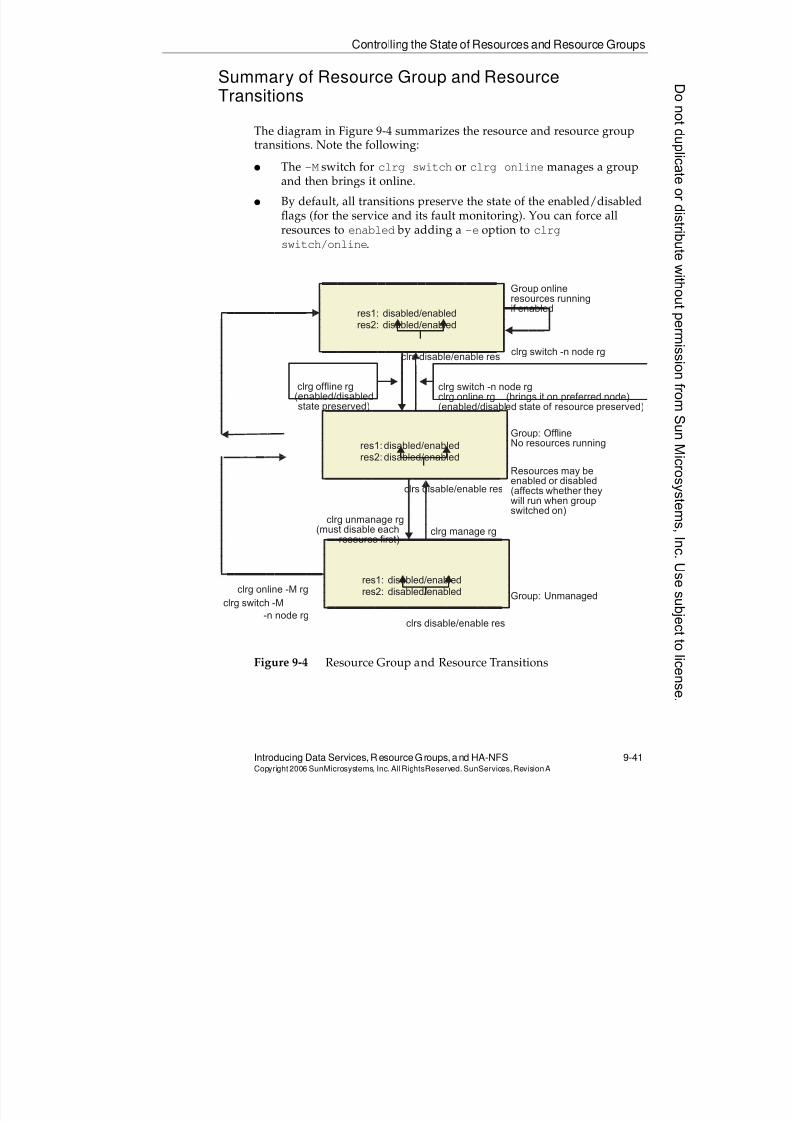
8/4/2019 Sun Cluster 3.2 Administration VC-ES-345
http://slidepdf.com/reader/full/sun-cluster-32-administration-vc-es-345 445/585
Controlling the State of Resources and Resource Groups
Introducing Data Services, ResourceGroups, and HA-NFS 9-41Copyright2006 SunMicrosystems, Inc. AllRightsReserved. SunServices,RevisionA
Summary of Resource Group and ResourceTransitions
The diagram in Figure 9-4 summarizes the resource and resource group
transitions. Note the following:q The -M switch for clrg switch or clrg online manages a group
and then brings it online.
q By default, all transitions preserve the state of the enabled/disabledflags (for the service and its fault monitoring). You can force allresources to enabled by adding a -e option to clrg
switch/online.
Figure 9-4 Resource Group and Resource Transitions
res1: disabled/enabledres2: disabled/enabled
clrs disable/enable res
clrg offline rg(enabled/disabledstate preserved)
clrg online -M rg
Group online
resources runningif enabled
clrg switch -n node rg
clrg switch -n node rgclrg online rg (brings it on preferred node)(enabled/disabled state of resource preserved)
Group: OfflineNo resources running
Resources may beenabled or disabled(affects whether theywill run when groupswitched on)
Group: Unmanaged
clrg unmanage rg(must disable each
resource first)clrg manage rg
res1: disabled/enabled
res2: disabled/enabled
clrs disable/enable res
res1: disabled/enabledres2: disabled/enabled
clrs disable/enable res
clrg switch -M-n node rg
8/4/2019 Sun Cluster 3.2 Administration VC-ES-345
http://slidepdf.com/reader/full/sun-cluster-32-administration-vc-es-345 446/585
Suspended Resource Groups
9-42 Sun™ Cluster 3.2 AdministrationCopyright2006 SunMicrosystems, Inc. AllRights Reserved.SunServices,RevisionA
Suspended Resource Groups
When you suspend a resource group, you disable any automatic recovery,failover, or restarting of the resource group or the resources within. Thatis:
q You can still transition the resource group any way you like usingthe commands presented on the previous pages.
q You can still enable/disable any individual resources, using thecommands presented on the previous pages. If the resource group isonline, the resources will go on and off accordingly.
q The fault monitors for resources will still be started.
q Resources will not automatically be restarted by fault monitors, norwill entire groups automatically fail over, even if an entire node fails.
The reason you might want to suspend an online resource group is toperform maintenance on it—that is, start and stop some applicationsmanually, but while preserving the online status of the group and othercomponents, so that dependencies can still be honored correctly.
The reason you might suspend an offline resource group is so that it doesnot go online automatically when you did not intend it to do so.
For example, when you put a resource group offline (but it is stillmanaged and not suspended), a node failure still causes the group to go
online.
To suspend a group, type:
# clrg suspend grpname
To remove the suspension of a group, type:
# clrg resume grpname
To see whether a group, is currently suspended, use clrg status , as
demonstrated on the next page.
Donotduplicate
ordistributewithoutpermissionfrom SunMicrosystems,Inc.Usesubject
tolicense.
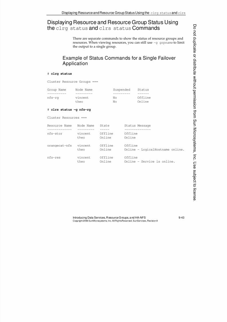
8/4/2019 Sun Cluster 3.2 Administration VC-ES-345
http://slidepdf.com/reader/full/sun-cluster-32-administration-vc-es-345 447/585
Displaying ResourceandResource GroupStatusUsing the clrg statusand clrs
Introducing Data Services, ResourceGroups, and HA-NFS 9-43Copyright2006 SunMicrosystems, Inc. AllRightsReserved. SunServices,RevisionA
Displaying Resource and Resource Group Status Usingthe clrg statusand clrs statusCommands
There are separate commands to show the status of resource groups and
resources. When viewing resources, you can still use -g grpname to limitthe output to a single group.
Example of Status Commands for a Single FailoverApplication
# clrg status
Cluster Resource Groups ===
Group Name Node Name Suspended Status
---------- --------- --------- ------
nfs-rg vincent No Offline
theo No Online
# clrs status -g nfs-rg
Cluster Resources ===
Resource Name Node Name State Status Message
------------- --------- ----- --------------nfs-stor vincent Offline Offline
theo Online Online
orangecat-nfs vincent Offline Offline
theo Online Online - LogicalHostname online.
nfs-res vincent Offline Offline
theo Online Online - Service is online.
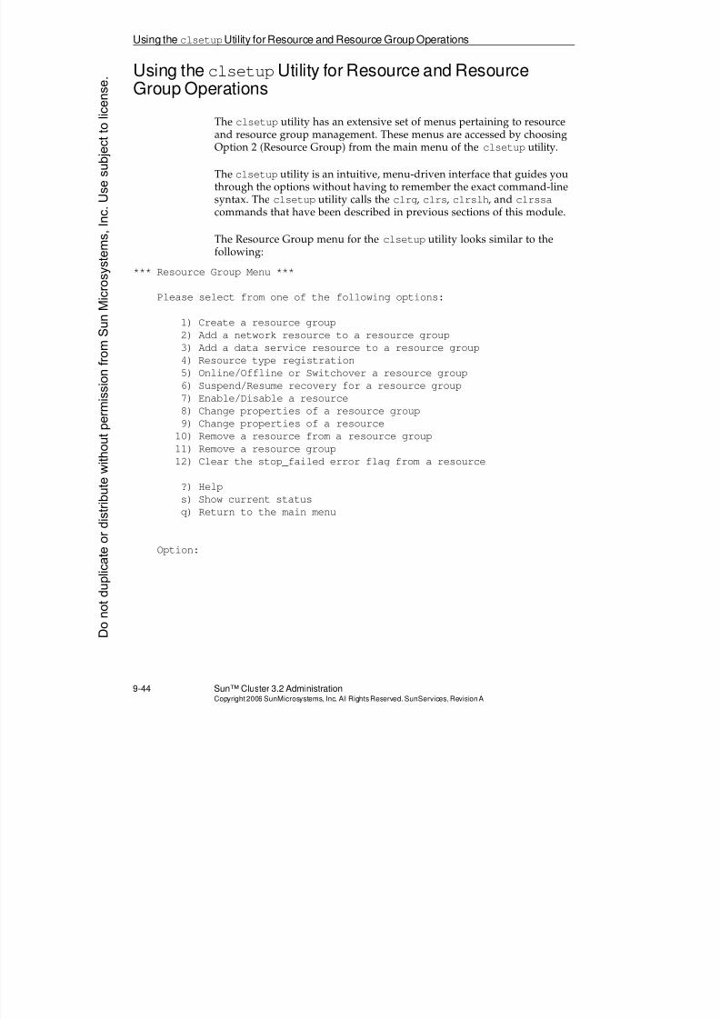
8/4/2019 Sun Cluster 3.2 Administration VC-ES-345
http://slidepdf.com/reader/full/sun-cluster-32-administration-vc-es-345 448/585
Using the clsetupUtility for Resource and Resource Group Operations
9-44 Sun™ Cluster 3.2 AdministrationCopyright2006 SunMicrosystems, Inc. AllRights Reserved.SunServices,RevisionA
Using the clsetupUtility for Resource and ResourceGroup Operations
The clsetup utility has an extensive set of menus pertaining to resource
and resource group management. These menus are accessed by choosingOption 2 (Resource Group) from the main menu of the clsetup utility.
The clsetup utility is an intuitive, menu-driven interface that guides youthrough the options without having to remember the exact command-linesyntax. The clsetup utility calls the clrg, clrs, clrslh, and clrssa
commands that have been described in previous sections of this module.
The Resource Group menu for the clsetup utility looks similar to thefollowing:
*** Resource Group Menu ***
Please select from one of the following options:
1) Create a resource group
2) Add a network resource to a resource group
3) Add a data service resource to a resource group
4) Resource type registration
5) Online/Offline or Switchover a resource group
6) Suspend/Resume recovery for a resource group
7) Enable/Disable a resource
8) Change properties of a resource group9) Change properties of a resource
10) Remove a resource from a resource group
11) Remove a resource group
12) Clear the stop_failed error flag from a resource
?) Help
s) Show current status
q) Return to the main menu
Option:
Donotduplicate
ordistributewithoutpermissionfrom SunMicrosystems,Inc.Usesubject
tolicense.
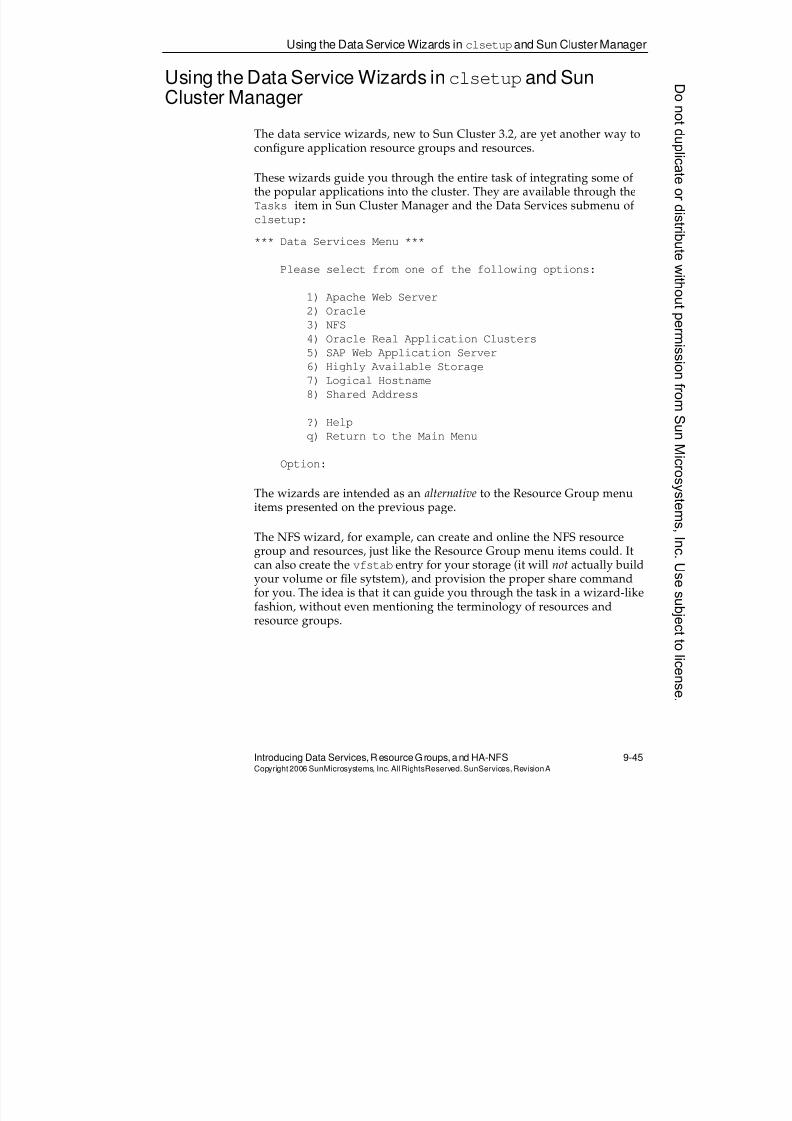
8/4/2019 Sun Cluster 3.2 Administration VC-ES-345
http://slidepdf.com/reader/full/sun-cluster-32-administration-vc-es-345 449/585
Using the Data Service Wizards inclsetupand Sun Cluster Manager
Introducing Data Services, ResourceGroups, and HA-NFS 9-45Copyright2006 SunMicrosystems, Inc. AllRightsReserved. SunServices,RevisionA
Using the Data Service Wizards inclsetupand SunCluster Manager
The data service wizards, new to Sun Cluster 3.2, are yet another way to
configure application resource groups and resources.
These wizards guide you through the entire task of integrating some ofthe popular applications into the cluster. They are available through theTasks item in Sun Cluster Manager and the Data Services submenu ofclsetup:
*** Data Services Menu ***
Please select from one of the following options:
1) Apache Web Server
2) Oracle
3) NFS
4) Oracle Real Application Clusters
5) SAP Web Application Server
6) Highly Available Storage
7) Logical Hostname
8) Shared Address
?) Help
q) Return to the Main Menu
Option:
The wizards are intended as an alternative to the Resource Group menuitems presented on the previous page.
The NFS wizard, for example, can create and online the NFS resourcegroup and resources, just like the Resource Group menu items could. Itcan also create the vfstab entry for your storage (it will not actually buildyour volume or file sytstem), and provision the proper share commandfor you. The idea is that it can guide you through the task in a wizard-like
fashion, without even mentioning the terminology of resources andresource groups.
8/4/2019 Sun Cluster 3.2 Administration VC-ES-345
http://slidepdf.com/reader/full/sun-cluster-32-administration-vc-es-345 450/585
Exercise: Installing and Configuring HA-NFS
9-46 Sun™ Cluster 3.2 AdministrationCopyright2006 SunMicrosystems, Inc. AllRights Reserved.SunServices,RevisionA
Exercise: Installing and Configuring HA-NFS
In this exercise, you complete the following tasks:
q Task 1 – Installing and Configuring the HA-NFS Agent and Server
q Task 2 – Registering and Configuring the Sun Cluster HA-NFS DataServices
q Task 3 – Verifying Access by NFS Clients
q Task 4 – Observing Sun Cluster HA-NFS Failover Behavior
q Task 5 – Generating Cluster Failures and Observing Behavior of theNFS Failover
q Task 6 – Configuring NFS to Use a Failover File System
q Task 7– Putting Failover Application Data in a ZFS File System
q Task 8 – Making a Customized Application Fail Over With a GenericData Service Resource
q Task 9– Viewing and Managing Resources and Resource GroupsUsing Sun Cluster Manager
Preparation
The following tasks are explained in this section:
q Preparing to register and configure the Sun Cluster HA for NFS dataservice
q Registering and configuring the Sun Cluster HA for NFS data service
q Verifying access by NFS clients
q Observing Sun Cluster HA for NFS failover behavior
Note – During this exercise, when you see italicized terms, such asIPaddress, enclosure_name, node1, or clustername, embedded in acommand string, substitute the names appropriate for your cluster.
Donotduplicate
ordistributewithoutpermissionfrom SunMicrosystems,Inc.Usesubject
tolicense.
8/4/2019 Sun Cluster 3.2 Administration VC-ES-345
http://slidepdf.com/reader/full/sun-cluster-32-administration-vc-es-345 451/585
Exercise: Installing and Configuring HA-NFS
Introducing Data Services, ResourceGroups, and HA-NFS 9-47Copyright2006 SunMicrosystems, Inc. AllRightsReserved. SunServices,RevisionA
Task 1 – Installing and Configuring the HA-NFS Agentand Server
In earlier exercises in Module 6, “Using VERITAS Volume Manager With
Sun Cluster Software,” or Module 7, “Using Solaris Volume ManagerWith Sun Cluster Software,” you created the global file system for NFS.Confirm that this file system is available and ready to configure for SunCluster HA for NFS.
Perform the following steps:
1. Install the Sun Cluster HA-NFS data service agent on all nodes:
# cd sc32_location/Solaris_sparc/Product
# cd sun_cluster_agents/Solaris_10/Packages
# pkgadd -d . SUNWscnfs
2. Modify the /etc/default/nfsfile on all nodes. Change the line thatcurrently reads:
GRACE_PERIOD=90
and lower the grace period to 10:
GRACE_PERIOD=10
Note – This should speed up HA-NFS switchovers and failovers. If yourclient and server are both running Solaris 10 OS, you will be using NFS
Version 4 by default. This is a stateful protocol which will intentionallydelay resumption of NFS activity so that clients have a chance to reclaimtheir state any time the server is recovering (which will include anycluster switchover or failover). The GRACE_PERIOD controls the length ofthe delay.
3. Verify that the /global/nfs file system is mounted and ready foruse.
# df -k
8/4/2019 Sun Cluster 3.2 Administration VC-ES-345
http://slidepdf.com/reader/full/sun-cluster-32-administration-vc-es-345 452/585
Exercise: Installing and Configuring HA-NFS
9-48 Sun™ Cluster 3.2 AdministrationCopyright2006 SunMicrosystems, Inc. AllRights Reserved.SunServices,RevisionA
4. Add an entry to the /etc/hostsfile on each cluster node and on theadministrative workstation for the logical host name resourceclustername-nfs. Substitute the IP address supplied by yourinstructor.
IP_address clustername-nfs
Note – In the RLDC, the /etc/hosts file on the vnchost already containsthe appropriate entry for each cluster. Verify that the entry for your clusterexists on the vnchost, and use the same IP address to create the entry onyour cluster nodes.
Perform the remaining steps on just one node of the cluster.
5. Create the administrative directory that contains the dfstab.nfs-res file for the NFS resource.
# cd /global/nfs
# mkdir admin
# cd admin
# mkdir SUNW.nfs
6. Create the dfstab.nfs-res file in the/global/nfs/admin/SUNW.nfsdirectory. Add the entry to share the/global/nfs/data directory.
# cd SUNW.nfs
# vi dfstab.nfs-res
share -F nfs -o rw /global/nfs/data
7. Create the directory specified in the dfstab.nfs-res file.
# cd /global/nfs
# mkdir /global/nfs/data
# chmod 777 /global/nfs/data
# touch /global/nfs/data/sample.file
Note – You are changing the mode of the data directory only for thepurposes of this lab. In practice, you would be more specific about theshare options in the dfstab.nfs-res file.
Donotduplicate
ordistributewithoutpermissionfrom SunMicrosystems,Inc.Usesubject
tolicense.
8/4/2019 Sun Cluster 3.2 Administration VC-ES-345
http://slidepdf.com/reader/full/sun-cluster-32-administration-vc-es-345 453/585
Exercise: Installing and Configuring HA-NFS
Introducing Data Services, ResourceGroups, and HA-NFS 9-49Copyright2006 SunMicrosystems, Inc. AllRightsReserved. SunServices,RevisionA
Task 2 – Registering and Configuring the Sun ClusterHA-NFS Data Services
Perform the following steps on one node only to configure HA-NFS in the
cluster:1. Register the NFS and SUNW.HAStoragePlus resource types.
# clrt register SUNW.nfs
# clrt register SUNW.HAStoragePlus
# clrt list -v
2. Create the failover resource group. Note that on a three-node clusterthe node list (specified with -n) can include nodes not physicallyconnected to the storage if you are using a global file system.
# clrg create -n node1,node2,[node3] \
-p Pathprefix=/global/nfs/admin nfs-rg
3. Create the logical host name resource to the resource group.
# clrslh create -g nfs-rg clustername-nfs
4. Create the SUNW.HAStoragePlus resource. If all of your nodes areconnected to the storage (two-node cluster, for example), you shouldset the value of AffinityOn to true. If you have a third, nonstoragenode, you should set the value of AffinityOn to false.
# clrs create -t HAStoragePlus -g nfs-rg \
-p AffinityOn=[true|false] \
-p FilesystemMountPoints=/global/nfs nfs-stor
5. Create the SUNW.nfs resource.
# clrs create -t nfs -g nfs-rg \
-p Resource_dependencies=nfs-stor nfs-res
6. Bring the resource group to a managed state and then online.
# clrg online -M nfs-rg
Note – The very first time you do this you may see a console warningmessage concerning “lockd: cannot contact statd”. Both daemons
are restarted (successfully) and you can ignore the message.
7. Verify that the data service is online.
# clrs list -v
# clrs status
# clrg status
8/4/2019 Sun Cluster 3.2 Administration VC-ES-345
http://slidepdf.com/reader/full/sun-cluster-32-administration-vc-es-345 454/585
Exercise: Installing and Configuring HA-NFS
9-50 Sun™ Cluster 3.2 AdministrationCopyright2006 SunMicrosystems, Inc. AllRights Reserved.SunServices,RevisionA
Task 3 – Verifying Access by NFS Clients
Perform the following steps to verify that NFS clients can access the filesystem of the Sun Cluster HA for NFS software package:
1. On the administration workstation, verify that you can access thecluster file system.
(# or $) ls /net/clustername-nfs/global/nfs/data
sample.file
2. On the administration workstation, copy the test.nfs file from thelab files location into your home directory.
3. Edit the $HOME/test.nfs script and verify that the logical host nameand NFS file system names are correct.
When this script is running, it creates and writes a file containing a
timestamp to your NFS-mounted file system. The script also displaysthe file to standard output (stdout). This script times how long theNFS data service is interrupted during switchovers and takeovers.
Donotduplicate
ordistributewithoutpermissionfrom SunMicrosystems,Inc.Usesubject
tolicense.
8/4/2019 Sun Cluster 3.2 Administration VC-ES-345
http://slidepdf.com/reader/full/sun-cluster-32-administration-vc-es-345 455/585
Exercise: Installing and Configuring HA-NFS
Introducing Data Services, ResourceGroups, and HA-NFS 9-51Copyright2006 SunMicrosystems, Inc. AllRightsReserved. SunServices,RevisionA
Task 4 – Observing Sun Cluster HA-NFS FailoverBehavior
Now that the Sun Cluster HA for NFS environment is working properly,
test its HA operation by performing the following steps:1. On the administration or display station, start the $HOME/test.nfs
script.
2. On one node of the cluster, determine the name of the node currentlyprimary for the nfs-rg resource group.
3. On one node of the cluster, transfer control of the NFS service fromone node to another.
# clrg switch -n dest-node nfs-rg
Substitute the name of your offline node for dest-node.
4. Observe the messages displayed by the test.nfs script.
5. How long was the data service interrupted during the switchoverfrom one physical host to another?
__________________________________________________
6. Use the df -k and share commands on all nodes to verify whichfile systems the nodes are now mounting and exporting.
__________________________________________________
__________________________________________________
__________________________________________________
7. Use the ifconfig command on all nodes to observe the additionalIP address associated with the Logical Hostname resourceconfigured as a virtual interface on one of the adapters in your IPMPgroup.
# ifconfig -a
8. On one node of the cluster, use the clrg switch command totransfer control of the NFS service back to its preferred host.
# clrg switch -n dest-node nfs-rg
8/4/2019 Sun Cluster 3.2 Administration VC-ES-345
http://slidepdf.com/reader/full/sun-cluster-32-administration-vc-es-345 456/585
Exercise: Installing and Configuring HA-NFS
9-52 Sun™ Cluster 3.2 AdministrationCopyright2006 SunMicrosystems, Inc. AllRights Reserved.SunServices,RevisionA
Task 5 – Generating Cluster Failures and ObservingBehavior of the NFS Failover
Generate failures in your cluster to observe the recovery features of Sun
Cluster 3.2 software. If you have physical access to the cluster, you canphysically pull out network cables or power down a node. If you do nothave physical access to the cluster, you can still bring a node to the ok
prompt using a break signal through your terminal concentrator.
Try to generate the following failures:
q Node failure (power down a node or bring it to the ok prompt)
q Single public network interface failure (pull a public network cable ,or sabotage the adapter using ifconfig modinsert as you did inModule 8)
q Multiple public network failure on a single node
Try your tests while the resource group is in its normal, nonsuspendedstate. Repeat some tests after suspending the resource group:
# clrg suspend nfs-rg
When you are satisfied with your results, remove the suspension:
# clrg resume nfs-rg
Donotduplicate
ordistributewithoutpermissionfrom SunMicrosystems,Inc.Usesubject
tolicense.
8/4/2019 Sun Cluster 3.2 Administration VC-ES-345
http://slidepdf.com/reader/full/sun-cluster-32-administration-vc-es-345 457/585
Exercise: Installing and Configuring HA-NFS
Introducing Data Services, ResourceGroups, and HA-NFS 9-53Copyright2006 SunMicrosystems, Inc. AllRightsReserved. SunServices,RevisionA
Task 6 – Configuring NFS to Use a Failover FileSystem
In this task, you configure NFS to use a failover file system rather than a
global file system.
Perform the following steps:
1. Disable the NFS resource group.
# clrg offline nfs-rg
2. If you have a nonstorage third node, delete the nonstorage node fromthe group node list, and set the affinity:
# clrg remove-node -n nonstorage-node-name nfs-rg
# clrs disable nfs-res
# clrs disable nfs-stor
# clrs set -p AffinityOn=TRUE nfs-stor
# clrs enable nfs-stor
# clrs enable nfs-res
3. Unmount the global NFS file system.
# umount /global/nfs
4. On each node, edit the /etc/vfstab file to make /global/nfs alocal file system (if you have a non-storage node, you can eithermake this edit, or just remove the line completely):
a. Change yes to no in the mount-at-boot column.
b. Remove the wordglobal from the mount options. Replace itwith a minus sign (-). Make sure you still have seven fields onthat line.
5. Restart the NFS resource group.
# clrg online nfs-rg
6. Observe the file system behavior. The file system should be mountedonly on the node running the NFS service and should fail overappropriately.
Note – Ordinarily, just by convention, you wouldn’t have a failover filesystem mounted under a subdirectory of /global. However, it is all just aconvention, and keeping the same mount point simplifies the flow ofthese exercises.
8/4/2019 Sun Cluster 3.2 Administration VC-ES-345
http://slidepdf.com/reader/full/sun-cluster-32-administration-vc-es-345 458/585
Exercise: Installing and Configuring HA-NFS
9-54 Sun™ Cluster 3.2 AdministrationCopyright2006 SunMicrosystems, Inc. AllRights Reserved.SunServices,RevisionA
Task 7– Putting Failover Application Data in a ZFS FileSystem
In this task, you will migrate your server-side data to a failover ZFS
filesystem.
Note – This task assumes that there are no longer any non-storage nodesincluded in your NFS resource group. This should be the case if you havecompleted Task 6. If you have a non-storage node in your resource group(and have not done Task 6), remove it from the group using clrg
remove-node -n nonstorage-node-name.
Peform the following steps only on the single node that is currently the primary for the NFS resource group:
1. Identify two unused disks (one in each storage array) that you canput into your ZFS pool. If you seem to already be “out of disks”,please consult your instructor about cleaning up.
2. Create a zpool that provides mirroring for your two disks:
# zpool create nfspool mirror c#t#d# c#t#d#
# zpool status
3. Create a ZFS file system within the pool:
# zfs create nfspool/nfs
# df -k
4. Disable your NFS service and migrate the data to your ZFS filesystem:
# clrs disable nfs-res
# clrs delete nfs-res
# cd /global/nfs
# find . -print|cpio -pdmuv /nfspool/nfs
# cd /
5. Disable your old (non-ZFS) NFS resource, and remount the ZFSunder /global/nfs. If you have already done task 6 then the
traditional /global/nfs is already a failover file system, and it will be unmounted by the clrs disable (so the umount is there just incase you had not done task 6).
# clrs disable nfs-stor
# clrs delete nfs-stor
# umount /global/nfs
# zfs set mountpoint=/global/nfs nfspool/nfsDonotduplicate
ordistributewithoutpermissionfrom SunMicrosystems,Inc.Usesubject
tolicense.
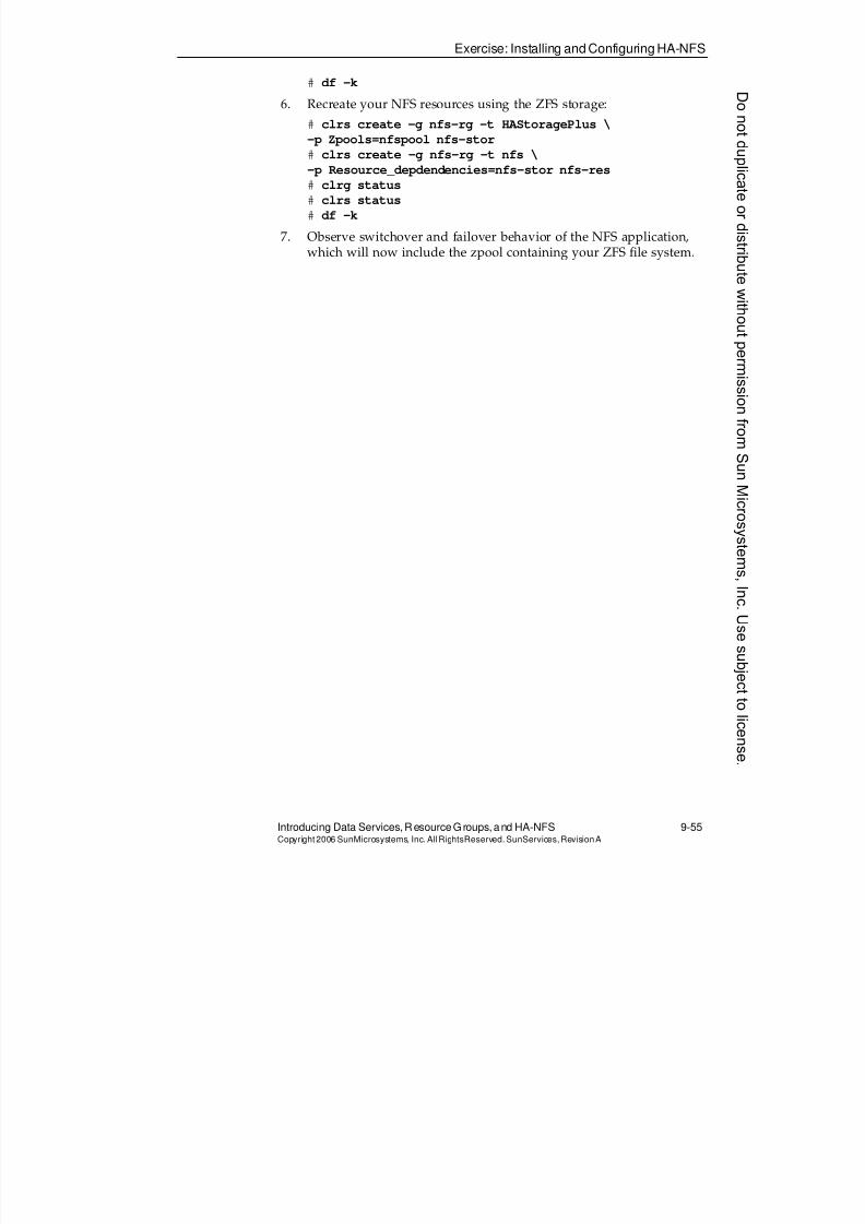
8/4/2019 Sun Cluster 3.2 Administration VC-ES-345
http://slidepdf.com/reader/full/sun-cluster-32-administration-vc-es-345 459/585
Exercise: Installing and Configuring HA-NFS
Introducing Data Services, ResourceGroups, and HA-NFS 9-55Copyright2006 SunMicrosystems, Inc. AllRightsReserved. SunServices,RevisionA
# df -k
6. Recreate your NFS resources using the ZFS storage:
# clrs create -g nfs-rg -t HAStoragePlus \
-p Zpools=nfspool nfs-stor
# clrs create -g nfs-rg -t nfs \
-p Resource_depdendencies=nfs-stor nfs-res# clrg status
# clrs status
# df -k
7. Observe switchover and failover behavior of the NFS application,which will now include the zpool containing your ZFS file system.
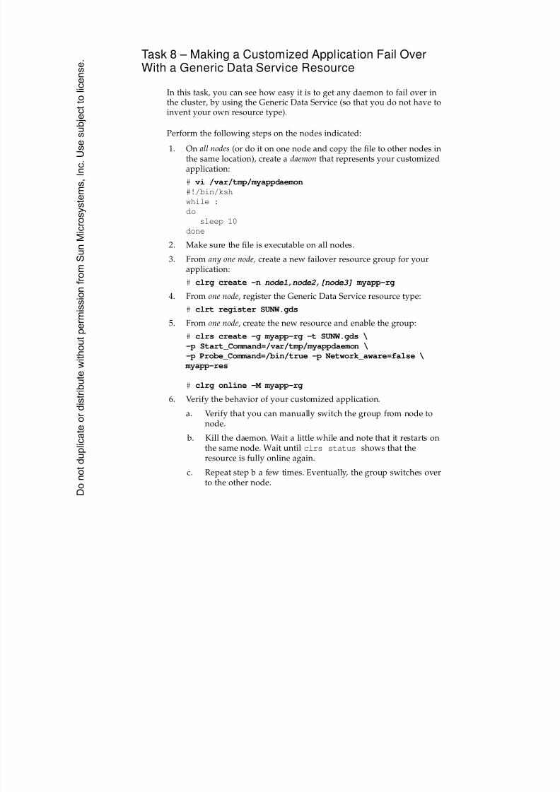
8/4/2019 Sun Cluster 3.2 Administration VC-ES-345
http://slidepdf.com/reader/full/sun-cluster-32-administration-vc-es-345 460/585
Task 8 – Making a Customized Application Fail OverWith a Generic Data Service Resource
In this task, you can see how easy it is to get any daemon to fail over in
the cluster, by using the Generic Data Service (so that you do not have toinvent your own resource type).
Perform the following steps on the nodes indicated:
1. On all nodes (or do it on one node and copy the file to other nodes inthe same location), create a daemon that represents your customizedapplication:
# vi /var/tmp/myappdaemon
#!/bin/ksh
while :
dosleep 10
done
2. Make sure the file is executable on all nodes.
3. From any one node, create a new failover resource group for yourapplication:
# clrg create -n node1,node2,[node3] myapp-rg
4. From one node, register the Generic Data Service resource type:
# clrt register SUNW.gds
5. From one node, create the new resource and enable the group:
# clrs create -g myapp-rg -t SUNW.gds \
-p Start_Command=/var/tmp/myappdaemon \
-p Probe_Command=/bin/true -p Network_aware=false \
myapp-res
# clrg online -M myapp-rg
6. Verify the behavior of your customized application.
a. Verify that you can manually switch the group from node to
node. b. Kill the daemon. Wait a little while and note that it restarts on
the same node. Wait until clrs status shows that theresource is fully online again.
c. Repeat step b a few times. Eventually, the group switches overto the other node.
Donotduplicate
ordistributewithoutpermissionfrom SunMicrosystems,Inc.Usesubject
tolicense.
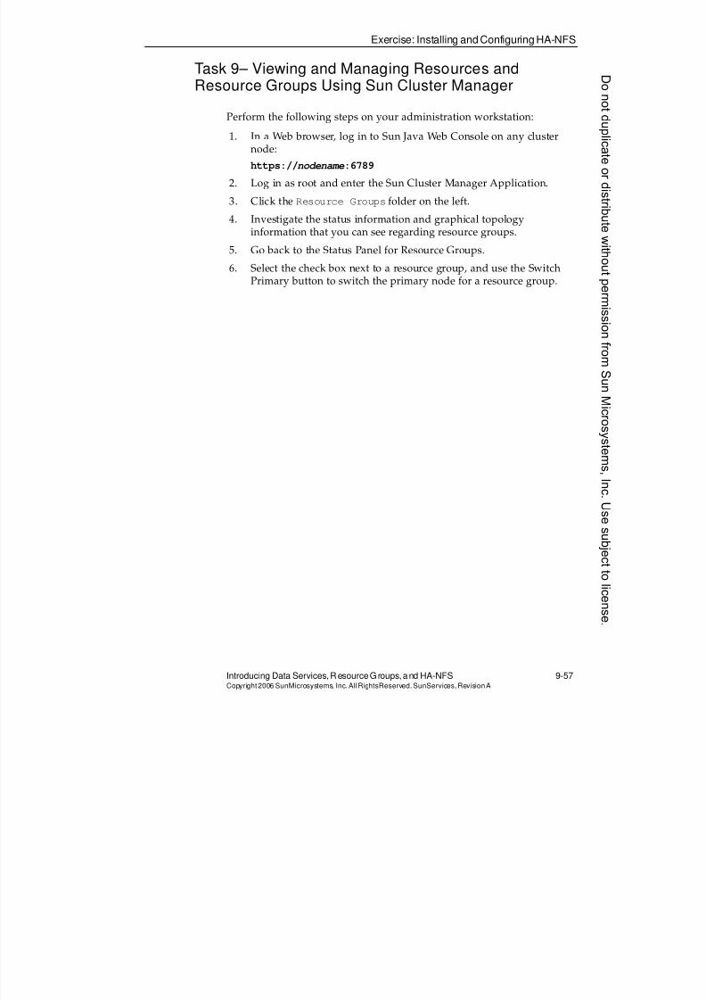
8/4/2019 Sun Cluster 3.2 Administration VC-ES-345
http://slidepdf.com/reader/full/sun-cluster-32-administration-vc-es-345 461/585
Exercise: Installing and Configuring HA-NFS
Introducing Data Services, ResourceGroups, and HA-NFS 9-57Copyright2006 SunMicrosystems, Inc. AllRightsReserved. SunServices,RevisionA
Task 9– Viewing and Managing Resources andResource Groups Using Sun Cluster Manager
Perform the following steps on your administration workstation:
1. In a Web browser, log in to Sun Java Web Console on any clusternode:
https://nodename:6789
2. Log in as root and enter the Sun Cluster Manager Application.
3. Click the Resource Groups folder on the left.
4. Investigate the status information and graphical topologyinformation that you can see regarding resource groups.
5. Go back to the Status Panel for Resource Groups.
6. Select the check box next to a resource group, and use the SwitchPrimary button to switch the primary node for a resource group.

8/4/2019 Sun Cluster 3.2 Administration VC-ES-345
http://slidepdf.com/reader/full/sun-cluster-32-administration-vc-es-345 462/585
Exercise Summary
9-58 Sun™ Cluster 3.2 AdministrationCopyright2006 SunMicrosystems, Inc. AllRights Reserved.SunServices,RevisionA
Exercise Summary
?
!
Discussion – Take a few minutes to discuss what experiences, issues, ordiscoveries you had during the lab exercises.
q Experiences
q Interpretations
q Conclusions
q Applications
Donotduplicate
ordistributewithoutpermissionfrom SunMicrosystems,Inc.Usesubject
tolicense.
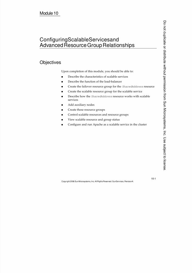
8/4/2019 Sun Cluster 3.2 Administration VC-ES-345
http://slidepdf.com/reader/full/sun-cluster-32-administration-vc-es-345 463/585
10-1Copyright2006 SunMicrosystems, Inc. AllRights Reserved.SunServices,RevisionA
Module 10
ConfiguringScalableServicesandAdvancedResourceGroupRelationships
Objectives
Upon completion of this module, you should be able to:
q Describe the characteristics of scalable services
q Describe the function of the load-balancer
q Create the failover resource group for the SharedAddress resource
q Create the scalable resource group for the scalable service
q Describe how the SharedAddress resource works with scalableservices
q Add auxiliary nodes
q
Create these resource groupsq Control scalable resources and resource groups
q View scalable resource and group status
q Configure and run Apache as a scalable service in the cluster
8/4/2019 Sun Cluster 3.2 Administration VC-ES-345
http://slidepdf.com/reader/full/sun-cluster-32-administration-vc-es-345 464/585
Relevance
10-2 Sun™ Cluster 3.2 AdministrationCopyright2006 SunMicrosystems, Inc. AllRights Reserved.SunServices,RevisionA
Relevance
?!
Discussion – The following questions are relevant to understanding the
content of this module:q Web servers are supported as scalable applications. But will every
application within a web server necesarily behave properly in ascalable environment?
q Why might you want a “client affinity” for load balancing?
q What reason might you have to have separate resource groups witha requirement that group A run only on a node also running groupB? Why not just combine them into one group?
Donotduplicate
ordistributewithoutpermissionfrom SunMicrosystems,Inc.Usesubject
tolicense.
8/4/2019 Sun Cluster 3.2 Administration VC-ES-345
http://slidepdf.com/reader/full/sun-cluster-32-administration-vc-es-345 465/585
Additional Resources
Configuring Scalable Services and Advanced Resource Group Relationships 10-3Copyright2006 SunMicrosystems, Inc. AllRightsReserved. SunServices,RevisionA
Additional Resources
Additional resources – The following references provide additional
information on the topics described in this module:q Sun Cluster™ System Administration Guide for Solaris™ OS, part
number 819-2971
q Sun Cluster Software Installation Guide for Solaris OS, part number 819-2970
q Sun Cluster Concepts Guide for Solaris OS, part number 819-2969
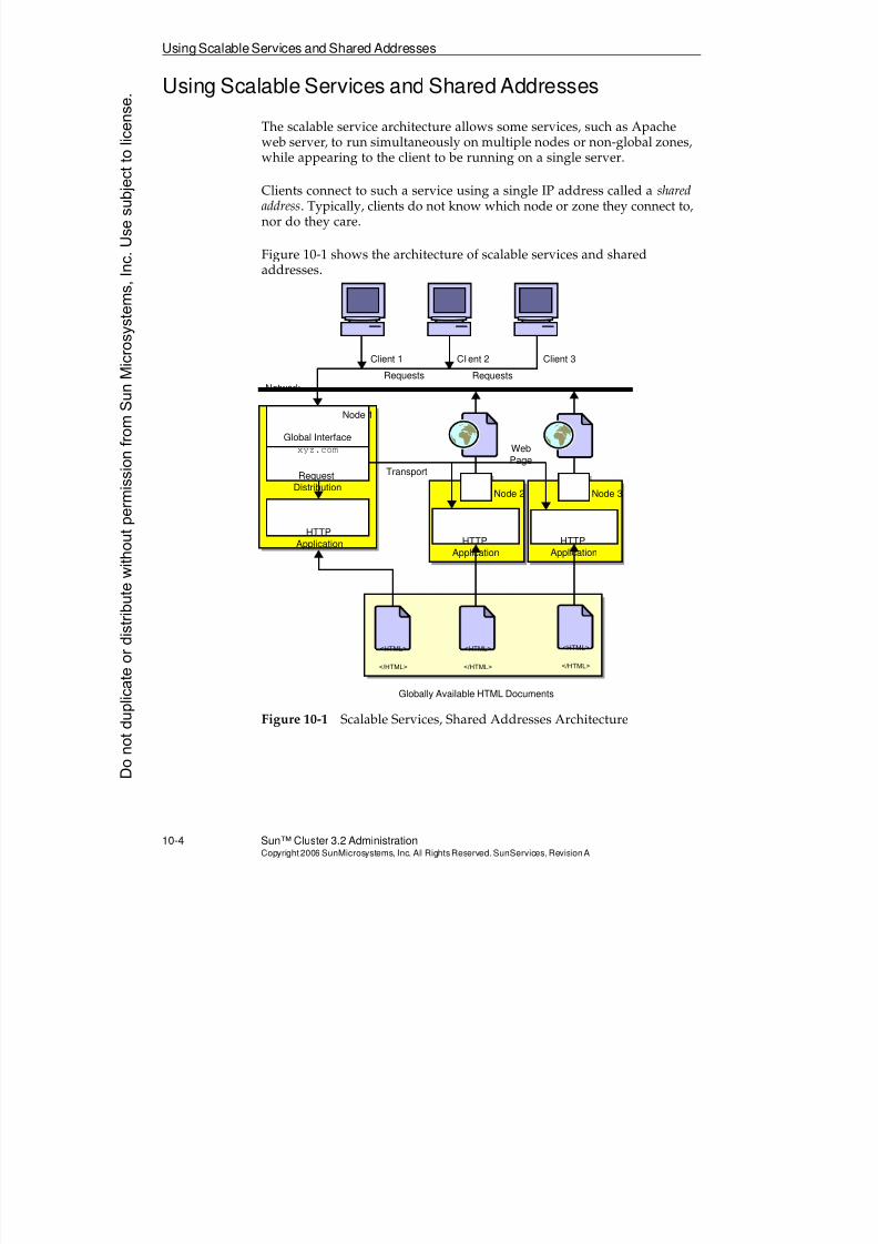
8/4/2019 Sun Cluster 3.2 Administration VC-ES-345
http://slidepdf.com/reader/full/sun-cluster-32-administration-vc-es-345 466/585
Using ScalableServices and Shared Addresses
10-4 Sun™ Cluster 3.2 AdministrationCopyright2006 SunMicrosystems, Inc. AllRights Reserved.SunServices,RevisionA
Using Scalable Services and Shared Addresses
The scalable service architecture allows some services, such as Apacheweb server, to run simultaneously on multiple nodes or non-global zones,while appearing to the client to be running on a single server.
Clients connect to such a service using a single IP address called a sharedaddress. Typically, clients do not know which node or zone they connect to,nor do they care.
Figure 10-1 shows the architecture of scalable services and sharedaddresses.
Figure 10-1 Scalable Services, Shared Addresses Architecture
<HTML>
</HTML>
<HTML>
</HTML>
<HTML>
</HTML>
Node 1
Node 2 Node 3
Globally Available HTML Documents
HTTP
Application HTTP
Application
HTTP
Application
Global Interface
xyz.com
Request
Distribution
Transport
Web
Page
Client 1 Client 2 Client 3
Requests Requests
Network
Donotduplicate
ordistributewithoutpermissionfrom SunMicrosystems,Inc.Usesubject
tolicense.
8/4/2019 Sun Cluster 3.2 Administration VC-ES-345
http://slidepdf.com/reader/full/sun-cluster-32-administration-vc-es-345 467/585
Exploring Characteristics of Scalable Services
Configuring Scalable Services and Advanced Resource Group Relationships 10-5Copyright2006 SunMicrosystems, Inc. AllRightsReserved. SunServices,RevisionA
Exploring Characteristics of Scalable Services
Similar to the failover services described in the previous modules, theapplications used as scalable services in theSun Cluster 3.2 environmentare generally off-the-shelf applications that are not specifically compiledor released to run in the cluster. The application binaries running on thevarious nodes are unaware of each other. This works because of the SunCluster 3.2 SharedAddressmechanism.
File and Data Access
Similar to the failover services, all the data for the scalable service must bein the shared storage.
Unlike the failover service, a file system-oriented scalable service must usethe global file system. A SUNW.HAStoragePlus resource can still be set upto manage dependencies between the service and the storage.
File Locking for Writing Data
One of the big barriers to taking just any application and turning it into ascalable service is that a service that is cluster-unaware may have beenwritten in such a way as to ignore file-locking issues.
In Sun Cluster 3.2 software, an application that performs datamodification without any type of locking or file synchronizationmechanism generally cannot be used as a scalable service.
While Sun Cluster 3.2 software provides the global data access methods, itdoes not automatically call any file-locking primitives for you.
Web servers that do file writing in common gateway interface (CGI)scripts, although not written specifically for a scalable platform, areusually written in such a way that multiple instances can be launched
simultaneously even on a stand-alone server. Therefore, they already havethe locking in place to make them ideal to work as scalable services in SunCluster 3.2 software.
Web servers that perform file writing using Java™ servlets must beexamined much more closely. A servlet might use thread synchronizationrather than file locking to enforce serial write access to a critical resource.This does not translate properly into a scalable service.
8/4/2019 Sun Cluster 3.2 Administration VC-ES-345
http://slidepdf.com/reader/full/sun-cluster-32-administration-vc-es-345 468/585
Using the SharedAddressResource
10-6 Sun™ Cluster 3.2 AdministrationCopyright2006 SunMicrosystems, Inc. AllRights Reserved.SunServices,RevisionA
Using the SharedAddressResource
The glue that holds a scalable service together in Sun Cluster 3.2 softwareis the SharedAddress resource.
This resource provides not only a single IP address that makes thescalable service look similar to a single server from the point of view ofthe client, but also provides the load balancing of requests to all the nodesor zones on which a scalable service is active.
Client Affinity
Certain types of applications require that load balancing in a scalableservice be on a per client basis, rather than a per connection basis. That is,
they require that the same client IP always have its requests forwarded tothe same node or zone. The prototypical example of an applicationrequiring such client affinity is a shopping cart application, where the stateof the client’s shopping cart is recorded only in the memory of theparticular node where the cart was created.
A single SharedAddress resource can provide standard (per connectionload balancing) and the type of sticky load balancing required byshopping carts. A scalable service’s agent registers which type of load balancing is required, based on a property of the data service.
Load-Balancing Weights
Sun Cluster 3.2 software also lets you control, on a scalable resource byscalable resource basis, the weighting that should be applied for load balancing. The default weighting is equal (connections or clients,depending on the stickiness) per node or zone, but through the use ofproperties described in the following sections, a better node or zone can bemade to handle a greater percentage of requests.
Note – You could have a single SharedAddress resource that providesload balancing for the same application using multiple IP addresses onthe same subnet. You could have multiple SharedAddress resources thatprovide load balancing for the same application using IP addresses ondifferent subnets. The load balancing properties discussed on this pageare set per scalable application, not per address.
Donotduplicate
ordistributewithoutpermissionfrom SunMicrosystems,Inc.Usesubject
tolicense.
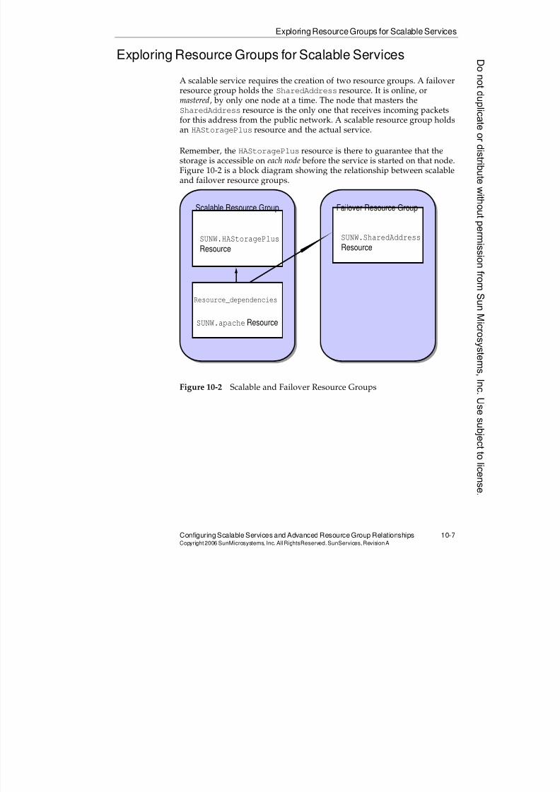
8/4/2019 Sun Cluster 3.2 Administration VC-ES-345
http://slidepdf.com/reader/full/sun-cluster-32-administration-vc-es-345 469/585
ExploringResourceGroups for Scalable Services
Configuring Scalable Services and Advanced Resource Group Relationships 10-7Copyright2006 SunMicrosystems, Inc. AllRightsReserved. SunServices,RevisionA
Exploring Resource Groups for Scalable Services
A scalable service requires the creation of two resource groups. A failoverresource group holds the SharedAddress resource. It is online, ormastered, by only one node at a time. The node that masters theSharedAddress resource is the only one that receives incoming packetsfor this address from the public network. A scalable resource group holdsan HAStoragePlus resource and the actual service.
Remember, the HAStoragePlus resource is there to guarantee that thestorage is accessible on each node before the service is started on that node.Figure 10-2 is a block diagram showing the relationship between scalableand failover resource groups.
Figure 10-2 Scalable and Failover Resource Groups
Scalable Resource Group Failover Resource Group
SUNW.HAStoragePlus
Resource
SUNW.SharedAddress
Resource
SUNW.apache Resource
Resource_dependencies
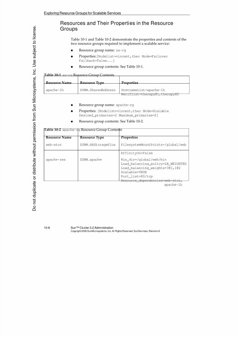
8/4/2019 Sun Cluster 3.2 Administration VC-ES-345
http://slidepdf.com/reader/full/sun-cluster-32-administration-vc-es-345 470/585
Exploring Resource Groups for Scalable Services
10-8 Sun™ Cluster 3.2 AdministrationCopyright2006 SunMicrosystems, Inc. AllRights Reserved.SunServices,RevisionA
Resources and Their Properties in the ResourceGroups
Table 10-1 and Table 10-2 demonstrate the properties and contents of the
two resource groups required to implement a scalable service:q Resource group name: sa-rg
q Properties:[Nodelist=vincent,theo Mode=Failover
Failback=False...]
q Resource group contents: See Table 10-1.
q Resource group name: apache-rg
q Properties: [Nodelist=vincent,theo Mode=Scalable
Desired_primaries=2 Maximum_primaries=2]
q Resource group contents: See Table 10-2.
Table 10-1 sa-rg Resource Group Contents
Resource Name Resource Type Properties
apache-lh SUNW.SharedAddress HostnameList=apache-lhNetiflist=therapy@1,therapy@2
Table 10-2 apache-rg Resource Group Contents
Resource Name Resource Type Properties
web-stor SUNW.HAStoragePlus FilesystemMountPoints=/global/web
AffinityOn=False
apache-res SUNW.apache Bin_dir=/global/web/bin
Load_balancing_policy=LB_WEIGHTED
Load_balancing_weights=3@1,1@2
Scalable=TRUE
Port_list=80/tcp
Resource_dependencies=web-stor,
apache-lh
Donotduplicate
ordistributewithoutpermissionfrom SunMicrosystems,Inc.Usesubject
tolicense.
8/4/2019 Sun Cluster 3.2 Administration VC-ES-345
http://slidepdf.com/reader/full/sun-cluster-32-administration-vc-es-345 471/585
Understanding Properties for Scalable Groups and Services
Configuring Scalable Services and Advanced Resource Group Relationships 10-9Copyright2006 SunMicrosystems, Inc. AllRightsReserved. SunServices,RevisionA
Understanding Properties for Scalable Groups andServices
Certain resource group properties and certain resource properties are of
particular importance for scalable services.
The Desired_primariesand Maximum_primariesProperties
These are group properties that indicate how many nodes the serviceshould run on. The rgmd tries to run the service on Desired_primaries
nodes, but you can manually switch it to using clrg switch, up toMaximum_primaries.
If these values are greater than 1, the Mode=Scalable property isautomatically set.
The Load_balancing_policyProperty
This is a property of the data service resource. It has one of the followingvalues:
q Lb_weighted – Client connections are all load balanced. This is the
default. Repeated connections from the same client might be serviced by different nodes.
q Lb_sticky – Connections from the same client IP to the same serverport all go to the same node. Load balancing is only for differentclients. This is only for the ports listed in the Port_list property.
q Lb_sticky_wild – Connections from the same client to any serverport go to the same node. This is good when port numbers aregenerated dynamically and not known in advance.
The Load_balancing_weightsProperty
This property controls the weighting of the load balancer. Default is evenfor all nodes. A value such as 3@1,1@2 indicates three times as manyconnections (or clients, with one of the sticky policies) serviced by node 1in the cluster compared to the number serviced by node 2.
8/4/2019 Sun Cluster 3.2 Administration VC-ES-345
http://slidepdf.com/reader/full/sun-cluster-32-administration-vc-es-345 472/585
Understanding Properties for Scalable Groups and Services
10-10 Sun™ Cluster 3.2 AdministrationCopyright2006 SunMicrosystems, Inc. AllRights Reserved.SunServices,RevisionA
The Resource_dependenciesProperty
You must set this property on a scalable resource. Its value must includethe SharedAddress resource (in the other resource group). This is used bythe data service agent to register the data service with the load balancer
associated with the SharedAddress resource.
The same Resource_dependenciesproperty of the scalable services alsotypically includes the HAStoragePlus resource in the same group.
Donotduplicate
ordistributewithoutpermissionfrom SunMicrosystems,Inc.Usesubject
tolicense.
8/4/2019 Sun Cluster 3.2 Administration VC-ES-345
http://slidepdf.com/reader/full/sun-cluster-32-administration-vc-es-345 473/585
Adding Auxiliary Nodes fora SharedAddressProperty
Configuring Scalable Services and Advanced Resource Group Relationships 10-11Copyright2006 SunMicrosystems, Inc. AllRightsReserved. SunServices,RevisionA
Adding Auxiliary Nodes for a SharedAddressProperty
The SharedAddress logic includes a routine whereby the actual IPaddress associated with the resource is configured on the public networkadapter (IPMP groups) on the primary node and is configured as a virtualaddress on the loopback network on all other nodes in its nodelist.
This enables scalable services that are running on nodes other than theprimary SharedAddress node to still bind to the IP address used for theSharedAddress.
However, the SharedAddress resource must know about all possiblenodes on which any scalable service associated with it might run.
If the node list for the SharedAddress resource group is a superset of the
node list of every scalable service that might run on it, you are fine. Butyou might want to restrict which nodes might be the primary for theSharedAddress, while still allowing a larger node list for the scalableservices dependent on it.
The SharedAddress resource has a special auxiliary nodes property thatallows you to augment the node list of its group, just for the purposes ofsupporting more nodes for scalable services. This is set with the -Xoptionto clrssa create.
In the following example, you want only nodes vincent and theo to be
the primaries for the SharedAddress (to actually host it on the public netand do the load balancing). But you might be supporting scalable servicesthat run on vincent, theo, and apricot:
# clrg create -n vincent,theo sa-rg
# clrssa create -g sa-rg -X apricot apache-lh
8/4/2019 Sun Cluster 3.2 Administration VC-ES-345
http://slidepdf.com/reader/full/sun-cluster-32-administration-vc-es-345 474/585
Reviewing Command Examples for a ScalableService
10-12 Sun™ Cluster 3.2 AdministrationCopyright2006 SunMicrosystems, Inc. AllRights Reserved.SunServices,RevisionA
Reviewing Command Examples for a Scalable Service
The following examples assume that the Apache web server agent wasadded from the Sun Cluster 3.2 Data Services CD using the Java ESinstaller or the pkgadd command.
1. Register the resource types by typing:
# clrt register SUNW.apache
# clrt register SUNW.HAStoragePlus
2. Create the failover resource group for the SharedAddress by typing:
# clrg create -n vincent,theo sa-rg
3. Create the SharedAddress resource by typing:
# clrssa create -g sa-rg apache-lh
4. Create the scalable resource group by typing:
# clrg create -n vincent,theo \
-p Desired_primaries=2 -p Maximum_primaries=2 \
apache-rg
5. Create the HAStoragePlus resource by typing:
# clrs create -t SUNW.HAStoragePlus -g apache-rg \
-p FilesystemMountPoints=/global/web \
-p AffinityOn=false \
web-stor
6. Create the Apache service by typing:
# clrs create -t SUNW.apache -g apache-rg \-p Resource_dependencies=web-stor,apache-lh \
-p Bin_dir=/global/web/bin \
-p Port_list=80/tcp \
-p Scalable=TRUE \
apache-res
7. Online the resource groups:
# clrg online sa-rg
# clrg online apache-rg
Donotduplicate
ordistributewithoutpermissionfrom SunMicrosystems,Inc.Usesubject
tolicense.
8/4/2019 Sun Cluster 3.2 Administration VC-ES-345
http://slidepdf.com/reader/full/sun-cluster-32-administration-vc-es-345 475/585
Controlling Scalable Resources and Resource Groups
Configuring Scalable Services and Advanced Resource Group Relationships 10-13Copyright2006 SunMicrosystems, Inc. AllRightsReserved. SunServices,RevisionA
Controlling Scalable Resources and Resource Groups
The following examples demonstrate how to use the clrg and clrs
commands to control the state of resource groups, resources, and dataservice fault monitors.
Resource Group Operations
Use the following commands to:
q Online an offline resource group onto its preferred nodes.
# clrg online [-M] [-e] apache-rg
q Online a resource group on specific nodes. Any nodes not mentionedare not affected (if the group is running on other nodes, it just stays
running there).
# clrg online -n node,node [-M] [-e] apache-rg
q Switch a scalable resource group to the specified nodes. On any othernodes, it is switched off.
# clrg switch [-M] [-e] -n node,node,.. apache-rg
q Offline a resource group (it goes off of all nodes):
# clrg offline [-M] [-e] apache-rg
q Offline a resource group on specific nodes. Any nodes not mentioned
are not affected (if the group is running on other nodes, it just staysrunning there).
# clrg offline -n node,node [-M] [-e] apache-rg
q Restart a resource group:
# clrg restart apache-rg
q Restart a resource group on a particular node or nodes:
# clrg restart -n node,node,... apache-rg
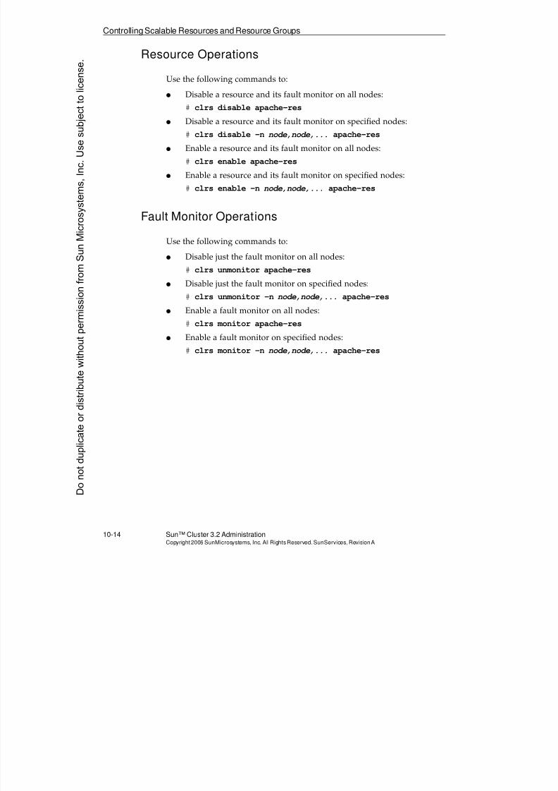
8/4/2019 Sun Cluster 3.2 Administration VC-ES-345
http://slidepdf.com/reader/full/sun-cluster-32-administration-vc-es-345 476/585
Controlling Scalable Resources and Resource Groups
10-14 Sun™ Cluster 3.2 AdministrationCopyright2006 SunMicrosystems, Inc. AllRights Reserved.SunServices,RevisionA
Resource Operations
Use the following commands to:
q Disable a resource and its fault monitor on all nodes:
# clrs disable apache-res
q Disable a resource and its fault monitor on specified nodes:
# clrs disable -n node,node,... apache-res
q Enable a resource and its fault monitor on all nodes:
# clrs enable apache-res
q Enable a resource and its fault monitor on specified nodes:
# clrs enable -n node,node,... apache-res
Fault Monitor Operations
Use the following commands to:
q Disable just the fault monitor on all nodes:
# clrs unmonitor apache-res
q Disable just the fault monitor on specified nodes:
# clrs unmonitor -n node,node,... apache-res
q Enable a fault monitor on all nodes:
# clrs monitor apache-res
q Enable a fault monitor on specified nodes:
# clrs monitor -n node,node,... apache-res
Donotduplicate
ordistributewithoutpermissionfrom SunMicrosystems,Inc.Usesubject
tolicense.
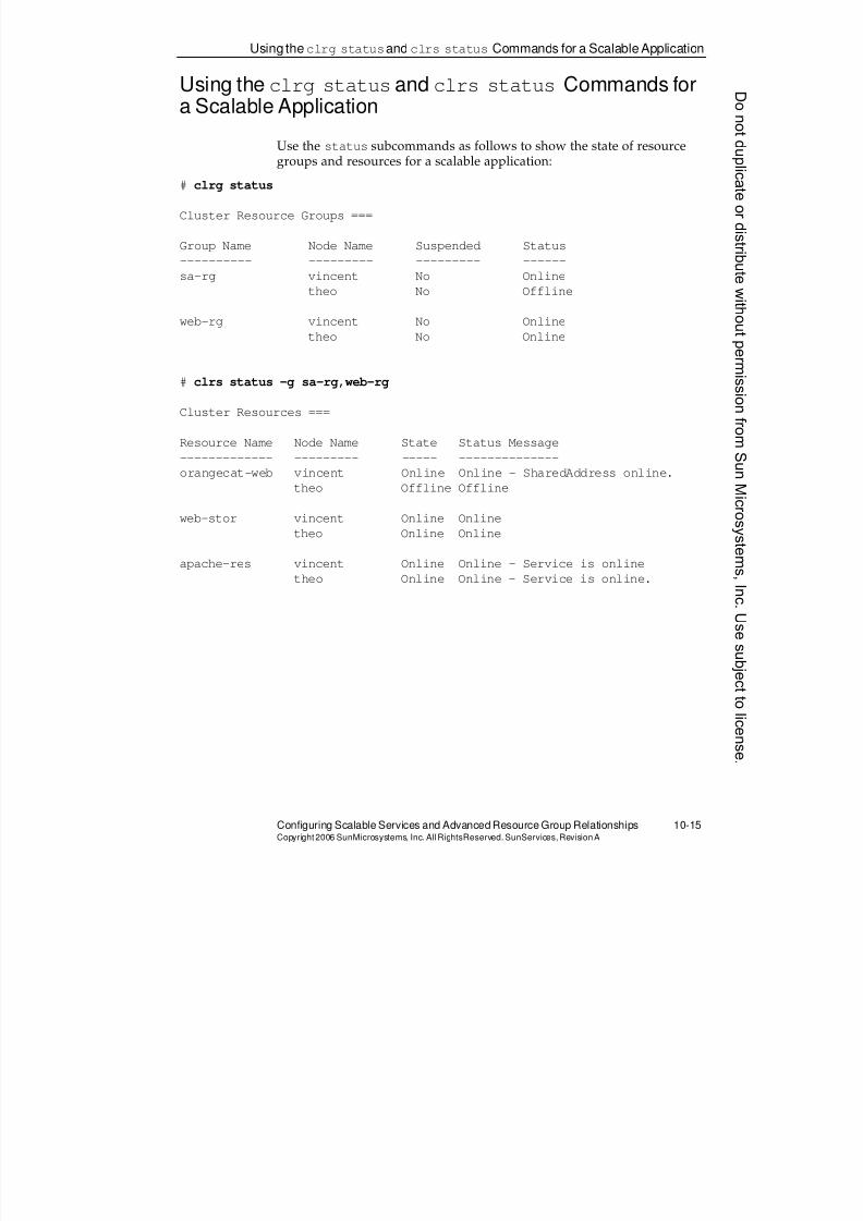
8/4/2019 Sun Cluster 3.2 Administration VC-ES-345
http://slidepdf.com/reader/full/sun-cluster-32-administration-vc-es-345 477/585
Using theclrg statusand clrs status Commands for a Scalable Application
Configuring Scalable Services and Advanced Resource Group Relationships 10-15Copyright2006 SunMicrosystems, Inc. AllRightsReserved. SunServices,RevisionA
Using the clrg statusand clrs status Commands fora Scalable Application
Use the status subcommands as follows to show the state of resource
groups and resources for a scalable application:# clrg status
Cluster Resource Groups ===
Group Name Node Name Suspended Status
---------- --------- --------- ------
sa-rg vincent No Online
theo No Offline
web-rg vincent No Online
theo No Online
# clrs status -g sa-rg,web-rg
Cluster Resources ===
Resource Name Node Name State Status Message
------------- --------- ----- --------------
orangecat-web vincent Online Online - SharedAddress online.
theo Offline Offline
web-stor vincent Online Online
theo Online Online
apache-res vincent Online Online - Service is online
theo Online Online - Service is online.

8/4/2019 Sun Cluster 3.2 Administration VC-ES-345
http://slidepdf.com/reader/full/sun-cluster-32-administration-vc-es-345 478/585
Advanced Resource Group Relationships
10-16 Sun™ Cluster 3.2 AdministrationCopyright2006 SunMicrosystems, Inc. AllRights Reserved.SunServices,RevisionA
Advanced Resource Group Relationships
Sun Cluster 3.2 software offers a series of advanced resource grouprelationships called resource group affinities.
Resource group affinities provide a mechanism for specifying either a preference (weak affinities) or a requirement (strong affinities) that certainresource groups either run on the same node (positive affinities) or do notrun on the same node (negative affinities).
In this section, the words source and target are used to refer to the resourcegroups with an affinities relationships. The source is the group for whichthe value of RG_affinities is set, and the target is the group referred to by the value of the property. So, in the following example:
# clrg set -p RG_affinities=++rg1 rg2
rg2 is referred to as the source and rg1 as the target.
Weak Positive Affinities and Weak Negative Affinities
The first two kinds of affinities place only a preference, not a requirement,on the location of the source group.
Setting a weak positive affinity says that the source group prefers to switch
to the node already running the target group, if any. If the target group isnot running at all, that is fine. You can freely switch online and offlineeither group, and freely, explicitly, place either on any node that you want.
Setting a weak negative affinity means that the source group prefers anyother node besides the target. Once again, it is just a preference. You canfreely, explicitly, place either group on whatever node you want.
Weak positive and weak negative group affinities are denoted by a singleplus or single minus sign, respectively.
In this example, group rg2 is given a weak positive affinity for rg1. Thisdoes not affect the current location of either group.
# clrg set -p RG_affinities=+rg1 rg2
WARNING: resource group rg2 declares a weak positive
affinity for resource group rg1; but this affinity is not
satisfied by the current state of the two resource groupsDonotduplicate
ordistributewithoutpermissionfrom SunMicrosystems,Inc.Usesubject
tolicense.
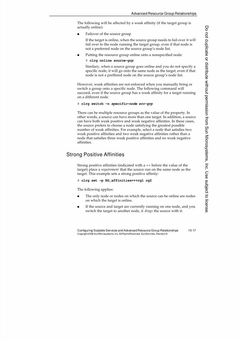
8/4/2019 Sun Cluster 3.2 Administration VC-ES-345
http://slidepdf.com/reader/full/sun-cluster-32-administration-vc-es-345 479/585
Advanced Resource Group Relationships
Configuring Scalable Services and Advanced Resource Group Relationships 10-17Copyright2006 SunMicrosystems, Inc. AllRightsReserved. SunServices,RevisionA
The following will be affected by a weak affinity (if the target group isactually online):
q Failover of the source group
If the target is online, when the source group needs to fail over it will
fail over to the node running the target group, even if that node isnot a preferred node on the source group’s node list.
q Putting the resource group online onto a nonspecified node:
# clrg online source-grp
Similary, when a source group goes online and you do not specify aspecific node, it will go onto the same node as the target, even if thatnode is not a preffered node on the source group’s node list.
However, weak affinities are not enforced when you manually bring orswitch a group onto a specific node. The following command will
succeed, even if the source group has a weak affinity for a target runningon a different node.
# clrg switch -n specific-node src-grp
There can be multiple resource groups as the value of the property. Inother words, a source can have more than one target. In addition, a sourcecan have both weak positive and weak negative affinities. In these cases,the source prefers to choose a node satisfying the greatest possiblenumber of weak affinities. For example, select a node that satisfies twoweak positive affinities and two weak negative affinities rather than a
node that satisfies three weak positive affinities and no weak negativeaffinities.
Strong Positive Affinities
Strong positive affinities (indicated with a ++ before the value of thetarget) place a requirement that the source run on the same node as thetarget. This example sets a strong positive affinity:
# clrg set -p RG_affinities=++rg1 rg2
The following applies:
q The only node or nodes on which the source can be online are nodeson which the target is online.
q If the source and target are currently running on one node, and youswitch the target to another node, it drags the source with it.
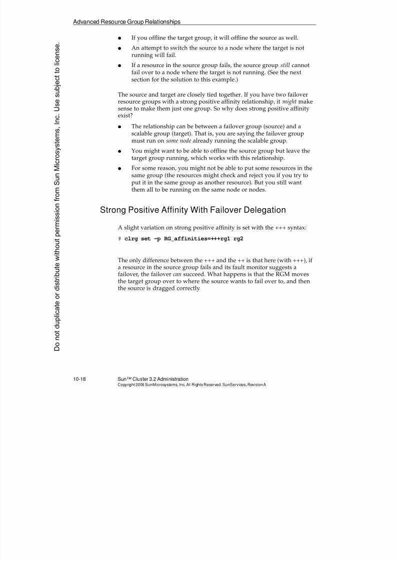
8/4/2019 Sun Cluster 3.2 Administration VC-ES-345
http://slidepdf.com/reader/full/sun-cluster-32-administration-vc-es-345 480/585
Advanced Resource Group Relationships
10-18 Sun™ Cluster 3.2 AdministrationCopyright2006 SunMicrosystems, Inc. AllRights Reserved.SunServices,RevisionA
q If you offline the target group, it will offline the source as well.
q An attempt to switch the source to a node where the target is notrunning will fail.
q If a resource in the source group fails, the source group still cannot
fail over to a node where the target is not running. (See the nextsection for the solution to this example.)
The source and target are closely tied together. If you have two failoverresource groups with a strong positive affinity relationship, it might makesense to make them just one group. So why does strong positive affinityexist?
q The relationship can be between a failover group (source) and ascalable group (target). That is, you are saying the failover groupmust run on some node already running the scalable group.
q You might want to be able to offline the source group but leave thetarget group running, which works with this relationship.
q For some reason, you might not be able to put some resources in thesame group (the resources might check and reject you if you try toput it in the same group as another resource). But you still wantthem all to be running on the same node or nodes.
Strong Positive Affinity With Failover Delegation
A slight variation on strong positive affinity is set with the +++ syntax:
# clrg set -p RG_affinities=+++rg1 rg2
The only difference between the +++ and the ++ is that here (with +++), ifa resource in the source group fails and its fault monitor suggests afailover, the failover can succeed. What happens is that the RGM movesthe target group over to where the source wants to fail over to, and thenthe source is dragged correctly.
Donotduplicate
ordistributewithoutpermissionfrom SunMicrosystems,Inc.Usesubject
tolicense.
8/4/2019 Sun Cluster 3.2 Administration VC-ES-345
http://slidepdf.com/reader/full/sun-cluster-32-administration-vc-es-345 481/585
Advanced Resource Group Relationships
Configuring Scalable Services and Advanced Resource Group Relationships 10-19Copyright2006 SunMicrosystems, Inc. AllRightsReserved. SunServices,RevisionA
Strong Negative Affinity
A strong negative affinity is set using the following syntax:
# clrg set -p RG_affinities=--rg1 rg2
Here, the source target cannot run on the same node as the target. Itabsolutely refuses to switch to any node where the target is running.
If you switch the target to the node where the source is running, it chasesthe source out of the way and the source switches to a different node, ifany. If there are no more nodes, the source switches off.
For example, if you have a two-node cluster with both the source andtarget groups online (on different nodes), and one node crashes(whichever it is), only the target group can remain running because the
source group absolutely, categorically refuses to run on the same node.
You need to be careful with strong negative affinities because the HA ofthe source group can be compromised.
8/4/2019 Sun Cluster 3.2 Administration VC-ES-345
http://slidepdf.com/reader/full/sun-cluster-32-administration-vc-es-345 482/585
Exercise: Installing andConfiguring Sun Cluster Scalable Service for Apache
10-20 Sun™ Cluster 3.2 AdministrationCopyright2006 SunMicrosystems, Inc. AllRights Reserved.SunServices,RevisionA
Exercise: Installing and Configuring Sun Cluster ScalableService for Apache
In this exercise, you complete the following tasks:
q Task 1 – Preparing for Apache Data Service Configuration
q Task 2 – Configuring the Apache Environment
q Task 3 – Testing the Server on Each Node Before Configuring theData Service Resources
q Task 4 – Registering and Configuring the Sun Cluster Apache DataService
q Task 5 – Verifying Apache Web Server Access
q Task 6 – Observing Cluster Failures
q Task 7 – Configuring Advanced Resource Group Relationships
Preparation
The following tasks are explained in this section:
q Preparing for Sun Cluster HA for Apache registration andconfiguration
q Registering and configuring the Sun Cluster HA for Apache data
serviceq Verifying Apache web server access and scalable capability
Note – During this exercise, when you see italicized names, such asIPaddress, enclosure_name, node1, or clustername embedded in acommand string, substitute the names appropriate for your cluster.
Donotduplicate
ordistributewithoutpermissionfrom SunMicrosystems,Inc.Usesubject
tolicense.
8/4/2019 Sun Cluster 3.2 Administration VC-ES-345
http://slidepdf.com/reader/full/sun-cluster-32-administration-vc-es-345 483/585
Exercise: Installing and ConfiguringSunCluster ScalableService for Apache
Configuring Scalable Services and Advanced Resource Group Relationships 10-21Copyright2006 SunMicrosystems, Inc. AllRightsReserved. SunServices,RevisionA
Task 1 – Preparing for Apache Data ServiceConfiguration
Perform the following steps on each node of the cluster:
1. Install the Sun Cluster Apache data service software package:# cd sc32_location/Solaris_sparc/Product
# cd sun_cluster_agents/Solaris_10/Packages
# pkgadd -d . SUNWscapc
2. Create an entry in /etc/hosts for the shared address you will beconfiguring with the Apache web server:
IP_address clustername-web
Note – In the RLDC, the vnchost already contains the appropriate entry
for each cluster. Verify that the entry for your cluster exists on thevnchost, and use the same IP address to create the entry on your clusternodes. In a non-RLDC environment, create the /etc/hosts entry on youradministrative workstation as well.
Task 2 – Configuring the Apache Environment
On (any) one node of the cluster, perform the following steps:
1. Make a resource-specific copy of the /usr/apache2/bin/apachectlscript and edit it:
# mkdir /global/web/bin
# cp /usr/apache2/bin/apachectl /global/web/bin
# vi /global/web/bin/apachectl
a. Add a line to make an Apache runtime directory. This directoryis deleted every time you reboot. Letting this script create itresolves the problem. Just add the line in bold as the second lineof the file:
#!/bin/sh
mkdir -p /var/run/apache2
b. Locate the line:
HTTPD='/usr/apache2/bin/httpd'
And change it to:
HTTPD='/usr/apache2/bin/httpd -f /global/web/conf/httpd.conf'
8/4/2019 Sun Cluster 3.2 Administration VC-ES-345
http://slidepdf.com/reader/full/sun-cluster-32-administration-vc-es-345 484/585
Exercise: Installing andConfiguring Sun Cluster Scalable Service for Apache
10-22 Sun™ Cluster 3.2 AdministrationCopyright2006 SunMicrosystems, Inc. AllRights Reserved.SunServices,RevisionA
2. Copy the sample /etc/apache2/httpd.conf-example to/global/web/conf/httpd.conf.
# mkdir /global/web/conf
# cp /etc/apache2/httpd.conf-example /global/web/conf/httpd.conf
3. Edit the /global/web/conf/httpd.conffile, and change thefollowing entries, as shown in Table 10-3. The changes are shown intheir order in the file, so you can search for the first place to change,change it, then search for the next, and so on.
4. Create directories for the Hypertext Markup Language (HTML)
and CGI files and populate with the sample files.
# cp -rp /var/apache2/htdocs /global/web
# cp -rp /var/apache2/cgi-bin /global/web
5. Copy the file called test-apache.cgi from the classroom server to/global/web/cgi-bin. You use this file to test the scalable service.Make sure that test-apache.cgi can be executed by all users.
# chmod 755 /global/web/cgi-bin/test-apache.cgi
Table 10-3 Entries in the /global/web/conf/httpd.confFile
Old Entry New Entry
KeepAlive On KeepAlive Off
Listen 80 Listen clustername-web:80
ServerName 127.0.0.1 ServerName clustername-web
DocumentRoot "/var/apache2/htdocs" DocumentRoot "/global/web/htdocs"
<Directory "/var/apache2/htdocs"> <Directory "/global/web/htdocs">
ScriptAlias /cgi-bin/
"/var/apache2/cgi-bin/" [one line]
ScriptAlias /cgi-bin/
"/global/web/cgi-bin/" [one line]
<Directory "/var/apache2/cgi-bin"> <Directory "/global/web/cgi-bin">
Donotduplicate
ordistributewithoutpermissionfrom SunMicrosystems,Inc.Usesubject
tolicense.
8/4/2019 Sun Cluster 3.2 Administration VC-ES-345
http://slidepdf.com/reader/full/sun-cluster-32-administration-vc-es-345 485/585
Exercise: Installing and ConfiguringSunCluster ScalableService for Apache
Configuring Scalable Services and Advanced Resource Group Relationships 10-23Copyright2006 SunMicrosystems, Inc. AllRightsReserved. SunServices,RevisionA
Task 3 – Testing the Server on Each Node BeforeConfiguring the Data Service Resources
Perform the following steps. Repeat the steps on each cluster node (one at
a time).1. Temporarily configure the logical shared address (on one node).
# ifconfig pubnet_adapter addif clustername-web netmask + broadcast + up
2. Start the server (on that node).
# /global/web/bin/apachectl start
3. Verify that the server is running.
vincent:/# ps -ef|grep apache2
webservd 4604 4601 0 10:20:05 ? 0:00 /usr/apache2/bin/httpd
-f /global/web/conf/httpd.conf -k start
webservd 4603 4601 0 10:20:05 ? 0:00 /usr/apache2/bin/httpd-f /global/web/conf/httpd.conf -k start
webservd 4605 4601 0 10:20:05 ? 0:00 /usr/apache2/bin/httpd
-f /global/web/conf/httpd.conf -k start
root 4601 1 0 10:20:04 ? 0:01 /usr/apache2/bin/httpd
-f /global/web/conf/httpd.conf -k start
webservd 4606 4601 0 10:20:05 ? 0:00 /usr/apache2/bin/httpd
-f /global/web/conf/httpd.conf -k start
webservd 4602 4601 0 10:20:05 ? 0:00 /usr/apache2/bin/httpd
-f /global/web/conf/httpd.conf -k start
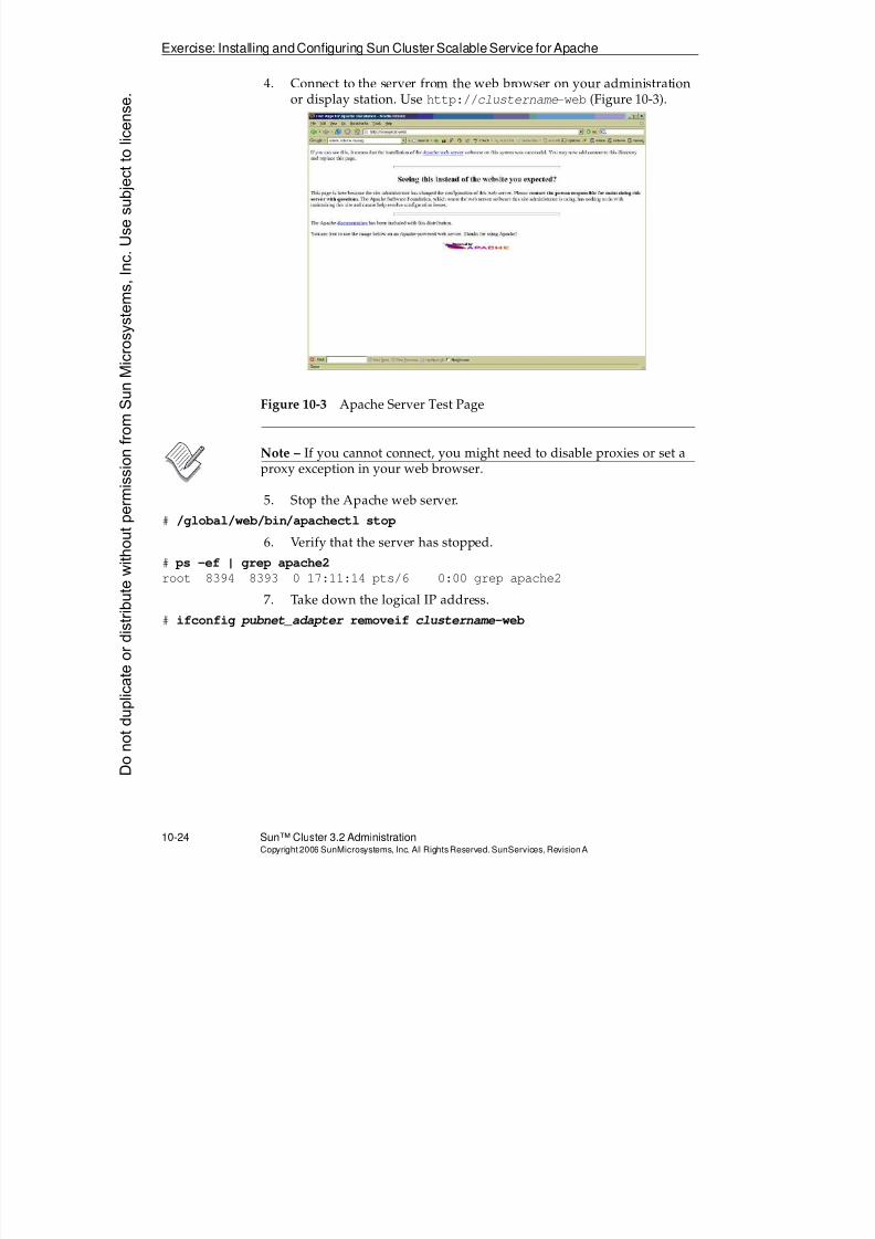
8/4/2019 Sun Cluster 3.2 Administration VC-ES-345
http://slidepdf.com/reader/full/sun-cluster-32-administration-vc-es-345 486/585
Exercise: Installing andConfiguring Sun Cluster Scalable Service for Apache
10-24 Sun™ Cluster 3.2 AdministrationCopyright2006 SunMicrosystems, Inc. AllRights Reserved.SunServices,RevisionA
4. Connect to the server from the web browser on your administrationor display station. Use http://clustername-web (Figure 10-3).
Figure 10-3 Apache Server Test Page
Note – If you cannot connect, you might need to disable proxies or set aproxy exception in your web browser.
5. Stop the Apache web server.# /global/web/bin/apachectl stop
6. Verify that the server has stopped.
# ps -ef | grep apache2
root 8394 8393 0 17:11:14 pts/6 0:00 grep apache2
7. Take down the logical IP address.
# ifconfig pubnet_adapter removeif clustername-web
Donotduplicate
ordistributewithoutpermissionfrom SunMicrosystems,Inc.Usesubject
tolicense.

8/4/2019 Sun Cluster 3.2 Administration VC-ES-345
http://slidepdf.com/reader/full/sun-cluster-32-administration-vc-es-345 487/585
Exercise: Installing and ConfiguringSunCluster ScalableService for Apache
Configuring Scalable Services and Advanced Resource Group Relationships 10-25Copyright2006 SunMicrosystems, Inc. AllRightsReserved. SunServices,RevisionA
Task 4 – Registering and Configuring the Sun ClusterApache Data Service
Perform the following steps only on (any) one node of the cluster:
1. Register the resource type required for the Apache data service.# clrt register SUNW.apache
2. Create a failover resource group for the shared address resource. Ifyou have more than two nodes, you can include more than twonodes after the -n.
# clrg create -n node1,node2 sa-rg
3. Create the SharedAddress logical host name resource to the resourcegroup.
# clrssa create -g sa-rg clustername- web
4. Bring the failover resource group online.
# clrg online -M sa-rg
5. Create a scalable resource group to run on all nodes of the cluster.(The example assumes two nodes.)
# clrg create -n node1,node2 -p Maximum_primaries=2 \
-p Desired_primaries=2 web-rg
6. Create a storage resource in the scalable group.
# clrs create -g web-rg -t SUNW.HAStoragePlus \
-p FilesystemMountPoints=/global/web -p AffinityOn=false web-stor
7. Create an application resource in the scalable resource group.
# clrs create -g web-rg -t SUNW.apache -p Bin_dir=/global/web/bin \
-p Scalable=TRUE -p Resource_dependencies=clustername-web,web-stor \
apache-res
8. Bring the scalable resource group online:
# clrg online -M web-rg
9. Verify that the data service is online.
# clrg status
# clrs status
8/4/2019 Sun Cluster 3.2 Administration VC-ES-345
http://slidepdf.com/reader/full/sun-cluster-32-administration-vc-es-345 488/585
Exercise: Installing andConfiguring Sun Cluster Scalable Service for Apache
10-26 Sun™ Cluster 3.2 AdministrationCopyright2006 SunMicrosystems, Inc. AllRights Reserved.SunServices,RevisionA
Task 5 – Verifying Apache Web Server Access
Perform the following steps to verify the Apache web server access andscalable utility:
1. Connect to the web server using the browser on the administratorworkstation using http://clustername-web/cgi-bin/test-
apache.cgi.
2. Repeatedly press the Refresh or Reload button on the browser. Thetest-apache.cgi script shows the name of the cluster node that iscurrently servicing the request. The load balancing is not performedon a round-robin basis, so you might see several consecutiverequests serviced by the same node. Over time, however, you shouldsee the load balancing be 50-50.
Task 6 – Observing Cluster Failures
Cause as many of the following failures (one at a time, and fix that one before going on to the next one) as you can, given your physical access tothe cluster.
Perform the following steps to observe the behavior of the scalableservice:
1. Fail a single public network interface on the node where the
SharedAddress resource is online.2. Fail all public network interfaces on that node.
3. Reboot one of the nodes running the scalable service.
4. Fail (or bring to the OK prompt) one of the nodes running thescalable service.
Donotduplicate
ordistributewithoutpermissionfrom SunMicrosystems,Inc.Usesubject
tolicense.
8/4/2019 Sun Cluster 3.2 Administration VC-ES-345
http://slidepdf.com/reader/full/sun-cluster-32-administration-vc-es-345 489/585
Exercise: Installing and ConfiguringSunCluster ScalableService for Apache
Configuring Scalable Services and Advanced Resource Group Relationships 10-27Copyright2006 SunMicrosystems, Inc. AllRightsReserved. SunServices,RevisionA
Task 7 – Configuring Advanced Resource GroupRelationships
In this task, you observe the effects of configuring variations of theRG_affinities
property.
Perform the following steps:
1. If you have not yet done so, complete Task 8 in Module 9.
2. Put your myapp-rg resource group offline:
# clrg offline myapp-rg
3. Put a strong negative affinity with the Apache resource group as thesource and myapp-rg as the target. This means that Apachecategorically refuses to run on any node where myapp-rg is running:
# clrg set -p RG_affinities=--myapp-rg web-rg
4. Switch the myapp-rg onto some node where Apache is running.Observe what happens to Apache. Observe the console messages aswell.
# clrg switch -n somenode myapp-rg
# clrg status
5. Switch the myapp-rg to another node where Apache is running.Observe what happens to Apache. Does it come back online on thefirst node?
# clrg switch -n othernode myapp-rg# clrg status
6. Switch the myapp-rg offline. Can Apache come back online on morenodes? Now remove the relationship:
# clrg offline myapp-rg
# clrg status
# clrg set -p RG_affinities="" web-rg
7. Set a weak positive affinity so that myapp-rg (source) always prefersto run on the same node as nfs-rg (target).
# clrg set -p RG_affinities=+nfs-rg myapp-rg
8. Print out the value of the Nodelist for myapp-rg.
# clrg show -p Nodelist myapp-rg
9. Switch your nfs-rg so that it is not on the preferred node of myapp-rg:
# clrg switch -n nonpreferrednode nfs-rg
8/4/2019 Sun Cluster 3.2 Administration VC-ES-345
http://slidepdf.com/reader/full/sun-cluster-32-administration-vc-es-345 490/585
Exercise: Installing andConfiguring Sun Cluster Scalable Service for Apache
10-28 Sun™ Cluster 3.2 AdministrationCopyright2006 SunMicrosystems, Inc. AllRights Reserved.SunServices,RevisionA
10. Put myapp-rg online without specifying the node. Where does it endup? Why does it not end up on the first node of its own node list?
# clrg online myapp-rg
# clrg status
11. Switch the myapp-rg so it is no longer on the same node as nfs-rg.Can you do it? Is a weak affinity a preference or a requirement?
# clrg switch -n othernode myapp-rg
# clrg status
12. Switch the myapp-rg offline and now change the affinity to a strongpositive affinity with delegation. What is the difference between ++and +++ (use +++)? The answer lies a few steps further on.
# clrg offline myapp-rg
# clrg set -p RG_affinities=+++nfs-rg myapp-rg
13. Put myapp-rg online without specifying the node. Where does it end
up?# clrg online myapp-rg
# clrg status
14. Switch the myapp-rg so it is no longer on the same node as nfs-rg.Can you do it?
# clrg switch -n othernode myapp-rg
# clrg status
15. What happens if you switch the target group nfs-rg?
# clrg switch -n othernode nfs-rg
# clrg status
16. What happens if RGM wants to failover the source myapp-rg because its fault monitor indicates application failure?
Kill myappdaemon on whichever node it is running a few times (bepatient with restarts) and observe.
Donotduplicate
ordistributewithoutpermissionfrom SunMicrosystems,Inc.Usesubject
tolicense.
8/4/2019 Sun Cluster 3.2 Administration VC-ES-345
http://slidepdf.com/reader/full/sun-cluster-32-administration-vc-es-345 491/585
Exercise Summary
Configuring Scalable Services and Advanced Resource Group Relationships 10-29Copyright2006 SunMicrosystems, Inc. AllRightsReserved. SunServices,RevisionA
Exercise Summary
?
!
Discussion – Take a few minutes to discuss what experiences, issues, ordiscoveries you had during the lab exercises.
q Experiences
q Interpretations
q Conclusions
q Applications

8/4/2019 Sun Cluster 3.2 Administration VC-ES-345
http://slidepdf.com/reader/full/sun-cluster-32-administration-vc-es-345 492/585
Do not duplicate or distribute without permission from Sun Microsystems, Inc. U
8/4/2019 Sun Cluster 3.2 Administration VC-ES-345
http://slidepdf.com/reader/full/sun-cluster-32-administration-vc-es-345 493/585
11-1Copyright2006 SunMicrosystems, Inc. AllRights Reserved.SunServices,RevisionA
Module 11
Performing SupplementalExercises forSunCluster 3.2Software
Objectives
Upon completion of this module, you should be able to:
q Configure a scalable application in non-global zones
q Configure HA-Oracle in a Sun Cluster 3.2 software environment as afailover application
q Configure Oracle RAC 10g in a Sun Cluster 3.2 softwareenvironment
8/4/2019 Sun Cluster 3.2 Administration VC-ES-345
http://slidepdf.com/reader/full/sun-cluster-32-administration-vc-es-345 494/585
Relevance
11-2 Sun™ Cluster 3.2 AdministrationCopyright2006 SunMicrosystems, Inc. AllRights Reserved.SunServices,RevisionA
Relevance
?!
Discussion – The following questions are relevant to understanding the
content this moduleq Why is it more difficult to install Oracle software for a standard
Oracle HA database on the local disks of each node rather thaninstalling it in the shared storage?
q Is there any advantage to installing software on the local disks ofeach node?
q How is managing Oracle RAC different from managing the othertypes of failover and scalable services presented in this course?
Donotduplicate
ordistributewithoutpermissionfrom SunMicrosystems,Inc.Usesubject
tolicense.
8/4/2019 Sun Cluster 3.2 Administration VC-ES-345
http://slidepdf.com/reader/full/sun-cluster-32-administration-vc-es-345 495/585
Additional Resources
Performing Supplemental Exercises for Sun Cluster 3.2 Software 11-3Copyright2006 SunMicrosystems, Inc. AllRightsReserved. SunServices,RevisionA
Additional Resources
Additional resources – The following references provide additional
information on the topics described in this module:
8/4/2019 Sun Cluster 3.2 Administration VC-ES-345
http://slidepdf.com/reader/full/sun-cluster-32-administration-vc-es-345 496/585
Exercise1: Runninga Clustered ScalableApplication in Non-global Zones
11-4 Sun™ Cluster 3.2 AdministrationCopyright2006 SunMicrosystems, Inc. AllRights Reserved.SunServices,RevisionA
Exercise 1: Running a Clustered Scalable Application inNon-global Zones
This exercise demonstrates running a clustered application in non-global
zones.
In this exercise, you complete the following tasks:
q Task 1 – Configuring and Installing the Zones
q Task 2 – Booting the Zones
q Task 3 – Modifying Your Resource Groups So Apache Runs in theNon-global Zones
q Task 4 – Verify That the Apache Application Is Running Correctly inthe Non-global Zones
Preparation
Before continuing with this exercise, read the background information inthis section.
Background – Running Clustered Applications in Zones
Many of the clustered applications are supported in non-global zones. The
resource group manager (RGM) is fully knowledgeable about zones andtreats them as if they were virtual nodes as far as configuring resourcegroups.
If you already have an application running across the physical nodes inthe cluster (global zone), it is a relatively simple operation to move it intoa non-global zone.
The same HAStoragePlus resource that is used to control global orfailover storage in global zones can be configured into a resource groupthat runs across non-global zones.
HAStoragePlusmethods automatically arrange for non-global zones togain access to your failover or global file system through simple loopbackmounts into the tree structure of each zone.
Donotduplicate
ordistributewithoutpermissionfrom SunMicrosystems,Inc.Usesubject
tolicense.
8/4/2019 Sun Cluster 3.2 Administration VC-ES-345
http://slidepdf.com/reader/full/sun-cluster-32-administration-vc-es-345 497/585
Exercise 1: Running a ClusteredScalable Application in Non-global Zones
Performing Supplemental Exercises for Sun Cluster 3.2 Software 11-5Copyright2006 SunMicrosystems, Inc. AllRightsReserved. SunServices,RevisionA
Task 1 – Configuring and Installing the Zones
Perform the following steps on all nodes. It can take a while to build yourzones, so get them up to where they are running the installation stage(step 2) simultaneously, so as not to waste time.
1. Allocate a dedicated public net IP address for the zone. Make sureyou use an IP that is not going to conflict with any other node orpreviously used application IP or IPMP test address. Make sure youuse a different IP for the zone on each node. You will identify theaddress in step 2. You are not required to put it in any /etc/hosts
file.
Note – Only scalable, load-balanced applications require a dedicated non-global zone IP address. You could run failover applications in non-global
zones without dedicated public network IP addresses in the zones.
2. Configure the zone.
# zonecfg -z myzone
myzone: No such zone configured
Use 'create' to begin configuring a new zone.
zonecfg:myzone> create
zonecfg:myzone> set zonepath=/myzone
zonecfg:myzone> set autoboot=true
zonecfg:myzone> add net
zonecfg:myzone:net> set address=x.y.z.w
zonecfg:myzone:net> set physical=node_pubnet_adapter
zonecfg:myzone:net> end
zonecfg:myzone> commit
zonecfg:myzone> exit
3. Install the zone.
# zoneadm -z myzone install
Preparing to install zone <myzone>.
Creating list of files to copy from the global zone.
.
.
.
The file </myzone/root/var/sadm/system/logs/install_log> contains a log
of the zone installation.
8/4/2019 Sun Cluster 3.2 Administration VC-ES-345
http://slidepdf.com/reader/full/sun-cluster-32-administration-vc-es-345 498/585
Exercise1: Runninga Clustered ScalableApplication in Non-global Zones
11-6 Sun™ Cluster 3.2 AdministrationCopyright2006 SunMicrosystems, Inc. AllRights Reserved.SunServices,RevisionA
Task 2 – Booting the Zones
On each node, perform the following steps:
1. Boot the zone.
# zoneadm -z myzone boot
2. Connect to the zone console and configure the zone. It will looksimilar to a standard Solaris™ OS that is booting after a sys-
unconfig:
# zlogin -C myzone
[Connected to zone 'myzone' console]
Wait until the SMF services are all loaded, and navigate through theconfiguration screens. Get your terminal type correct, or you mayhave trouble with the rest of the configuration screens.
Note – While the zone on each node will have the same zone name(myzone), give each zone a different Solaris host name in the configurationscreens (myzone-nodename), so you can distinguish between them (and sothat the Apache proof of concept CGI program will make sense).
When you have finished the system configuration in the zone, it willreboot automatically. You can stay connected to the zone console
3. Edit the /etc/hosts file in the zone (on each node) and add the IPaddress for clustername-web. Use the same name and IP address
that you have in the /etc/hosts file in the global zone.
4. Edit the /etc/default/loginfile in the zone to allow root logins:
# vi /etc/default/login
[Comment out the CONSOLE=/dev/console line]
# exit
5. Disconnect from the zone console using ~.
# vi /etc/default/login
[Comment out the CONSOLE=/dev/console line]
# exit
6. Disconnect from the zone console using ~.
Donotduplicate
ordistributewithoutpermissionfrom SunMicrosystems,Inc.Usesubject
tolicense.
8/4/2019 Sun Cluster 3.2 Administration VC-ES-345
http://slidepdf.com/reader/full/sun-cluster-32-administration-vc-es-345 499/585
Exercise 1: Running a ClusteredScalable Application in Non-global Zones
Performing Supplemental Exercises for Sun Cluster 3.2 Software 11-7Copyright2006 SunMicrosystems, Inc. AllRightsReserved. SunServices,RevisionA
Task 3 – Modifying Your Resource Groups So ApacheRuns in the Non-global Zones
Perform the following in the global zone on the nodes indicated:
1. From any one node, offline the scalable and shared address resourcegroups:
# clrg offline web-rg sa-rg
2. On all nodes (still in the global zone), manually do a loopback mountof the /global/web filesystem. This will allow the apache resourceto validate correctly when the node list of its group is changed to thezones. Once the resource group is running in the zones, theHAStoragePlusmethods will automatically be doing the mounts.
# mkdir -p /myzone/root/global/web
# mount -F lofs /global/web /myzone/root/global/web
3. From any one node, modify the node lists:
# clrg set -n node1:myzone,node2:myzone[,node3:myzone] sa-rg
# clrg set -n node1:myzone,node2:myzone[,node3:myzone] web-rg
4. From any one node, unmanage and then remanage all the groups.This is required to properly reconfigure the shared address in all thezones, and start the load-balanced service:
# clrs disable -g sa-rg,web-rg +
# clrg unmanage sa-rg web-rg
# clrg online -Me sa-rg web-rg
Note – You may see console messages about the scalable service beingregistered with the physical node name, although the application willreally be running in the zone. This is normal.
8/4/2019 Sun Cluster 3.2 Administration VC-ES-345
http://slidepdf.com/reader/full/sun-cluster-32-administration-vc-es-345 500/585
Exercise1: Runninga Clustered ScalableApplication in Non-global Zones
11-8 Sun™ Cluster 3.2 AdministrationCopyright2006 SunMicrosystems, Inc. AllRights Reserved.SunServices,RevisionA
Task 4 – Verify That the Apache Application Is RunningCorrectly in the Non-global Zones
Perform the following steps to verify the correct operation of Apache, and
to demonstrate that the load balancing is working when the scalableapplication is running across non-global zones.
1. On any node, from the global zone, verify the cluster applicationstatus:
# clrg status
# clrs status
2. On each node, log in to the non-global zone and verify that theApache application is running inside the zone:
# zlogin myzone
(in the non-global zone)
# ps -ef|grep apache2
# exit
3. On the administration workstation or display, point a Web browserto http://clustername-web/cgi-bin/test-apache.cgi. Pressreload or refresh several times to demonstrate that load balancing isworking across the zones. It is not round-robin load balancing;therefore, you might get a response from the same zone several timesin a row.
Donotduplicate
ordistributewithoutpermissionfrom SunMicrosystems,Inc.Usesubject
tolicense.
8/4/2019 Sun Cluster 3.2 Administration VC-ES-345
http://slidepdf.com/reader/full/sun-cluster-32-administration-vc-es-345 501/585
Exercise 2: Integrating Oracle 10g Into Sun Cluster 3.2 Software as a Failover
Performing Supplemental Exercises for Sun Cluster 3.2 Software 11-9Copyright2006 SunMicrosystems, Inc. AllRightsReserved. SunServices,RevisionA
Exercise 2: Integrating Oracle 10g Into Sun Cluster 3.2Software as a Failover Application
In this exercise you integrate Oracle 10g into Sun Cluster 3.2 software as a
failover application.
In this exercise, you complete the following tasks:
q Task 1 – Creating a Logical IP Entry in the /etc/hosts File
q Task 2 – Creating oracle and dba Accounts
q Task 3 – Creating a Shared Storage File System for Oracle Software(VxVM)
q Task 4 – Creating a Shared Storage File System for Oracle Software(SVM)
q Task 5 – Preparing the oracle User Environment
q Task 6 – Disabling Access Control of X Server on the AdminWorkstation
q Task 7 – Running the runInstaller Installation Script
q Task 8 – Preparing an Oracle Instance for Cluster Integration
q Task 9 – Verifying That Oracle Software Runs on Other Nodes
q Task 10 – Registering the SUNW.HAStoragePlusType
q Task 11 – Installing and Registering Oracle Data Service
q Task 12 – Creating Resources and Resource Groups for Oracle
q Task 13 – Verifying That Oracle Runs Properly in the Cluster
Preparation
Before continuing with this exercise, read the background information inthis section.
8/4/2019 Sun Cluster 3.2 Administration VC-ES-345
http://slidepdf.com/reader/full/sun-cluster-32-administration-vc-es-345 502/585
Exercise2: Integrating Oracle 10g Into Sun Cluster 3.2Software as a Failover
11-10 Sun™ Cluster 3.2 AdministrationCopyright2006 SunMicrosystems, Inc. AllRights Reserved.SunServices,RevisionA
Background
It is relatively straightforward to configure the Oracle 10g Databasesoftware as a failover application in the Sun Cluster 3.2 environment. Likethe majority of failover applications, the Oracle software is “cluster-
unaware.” You will be installing and configuring the software exactly asyou would on a stand-alone system and then manipulating theconfiguration so that it listens on a failover logical IP address.
Installing an Application on Local Storage (Each Node) or SharedStorage
For ease of installation and management, this lab takes the strategy ofinstalling the Oracle binaries themselves directly in shared storage.Therefore, you only need to perform the Oracle installation once. Thedisadvantage is that there would be no way to perform maintenance orpatching on the software while keeping your application available onanother node.
In production, you might want to install separate copies of the softwarelocally on each node (with the data, of course, being in the sharedstorage). While it is more difficult to install, you get the advantage of being able to perform rolling maintenance (including patching) of thesoftware on one node while keeping your database alive on the othernode.
Using a Failover File System or Global File System on SharedStorage
A failover file system is optimal for performance (although actual failovertime is longer, the application runs faster after it is up and running).
However, you cannot use a failover file system if you want yourapplication to fail over to a nonstorage node.
This exercise uses a global file system because some lab environments
might have nonstorage nodes. When you install Oracle, you will mountthe file system with the noglobal flag to speed up the installation.
Donotduplicate
ordistributewithoutpermissionfrom SunMicrosystems,Inc.Usesubject
tolicense.
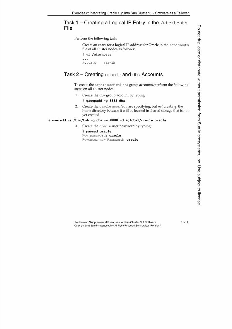
8/4/2019 Sun Cluster 3.2 Administration VC-ES-345
http://slidepdf.com/reader/full/sun-cluster-32-administration-vc-es-345 503/585
Exercise 2: Integrating Oracle 10g Into Sun Cluster 3.2 Software as a Failover
Performing Supplemental Exercises for Sun Cluster 3.2 Software 11-11Copyright2006 SunMicrosystems, Inc. AllRightsReserved. SunServices,RevisionA
Task 1 – Creating a Logical IP Entry in the /etc/hostsFile
Perform the following task:
Create an entry for a logical IP address for Oracle in the /etc/hostsfile of all cluster nodes as follows:
# vi /etc/hosts
...
x.y.z.w ora-lh
Task 2 – Creating oracle and dbaAccounts
To create the oracleuser and dba group accounts, perform the following
steps on all cluster nodes:
1. Create the dba group account by typing:
# groupadd -g 8888 dba
2. Create the oracle user. You are specifying, but not creating, thehome directory because it will be located in shared storage that is notyet created.
# useradd -s /bin/ksh -g dba -u 8888 -d /global/oracle oracle
3. Create the oracle user password by typing:
# passwd oracle
New password: oracle
Re-enter new Password: oracle
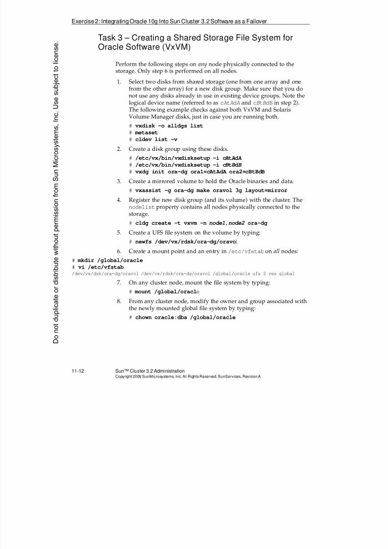
8/4/2019 Sun Cluster 3.2 Administration VC-ES-345
http://slidepdf.com/reader/full/sun-cluster-32-administration-vc-es-345 504/585
Exercise2: Integrating Oracle 10g Into Sun Cluster 3.2Software as a Failover
11-12 Sun™ Cluster 3.2 AdministrationCopyright2006 SunMicrosystems, Inc. AllRights Reserved.SunServices,RevisionA
Task 3 – Creating a Shared Storage File System forOracle Software (VxVM)
Perform the following steps on any node physically connected to the
storage. Only step 6 is performed on all nodes.1. Select two disks from shared storage (one from one array and one
from the other array) for a new disk group. Make sure that you donot use any disks already in use in existing device groups. Note thelogical device name (referred to as cAtAdA and cBtBdB in step 2).The following example checks against both VxVM and SolarisVolume Manager disks, just in case you are running both.
# vxdisk -o alldgs list
# metaset
# cldev list -v
2. Create a disk group using these disks.# /etc/vx/bin/vxdisksetup -i c A t A d A
# /etc/vx/bin/vxdisksetup -i cB tB dB
# vxdg init ora-dg ora1=cAtAdA ora2=cBtBdB
3. Create a mirrored volume to hold the Oracle binaries and data.
# vxassist -g ora-dg make oravol 3g layout=mirror
4. Register the new disk group (and its volume) with the cluster. Thenodelist property contains all nodes physically connected to thestorage.
# cldg create -t vxvm -n node1,node2 ora-dg
5. Create a UFS file system on the volume by typing:
# newfs /dev/vx/rdsk/ora-dg/oravol
6. Create a mount point and an entry in /etc/vfstab on all nodes:
# mkdir /global/oracle
# vi /etc/vfstab/dev/vx/dsk/ora-dg/oravol /dev/vx/rdsk/ora-dg/oravol /global/oracle ufs 2 yes global
7. On any cluster node, mount the file system by typing:
# mount /global/oracle
8. From any cluster node, modify the owner and group associated withthe newly mounted global file system by typing:
# chown oracle:dba /global/oracle
Donotduplicate
ordistributewithoutpermissionfrom SunMicrosystems,Inc.Usesubject
tolicense.
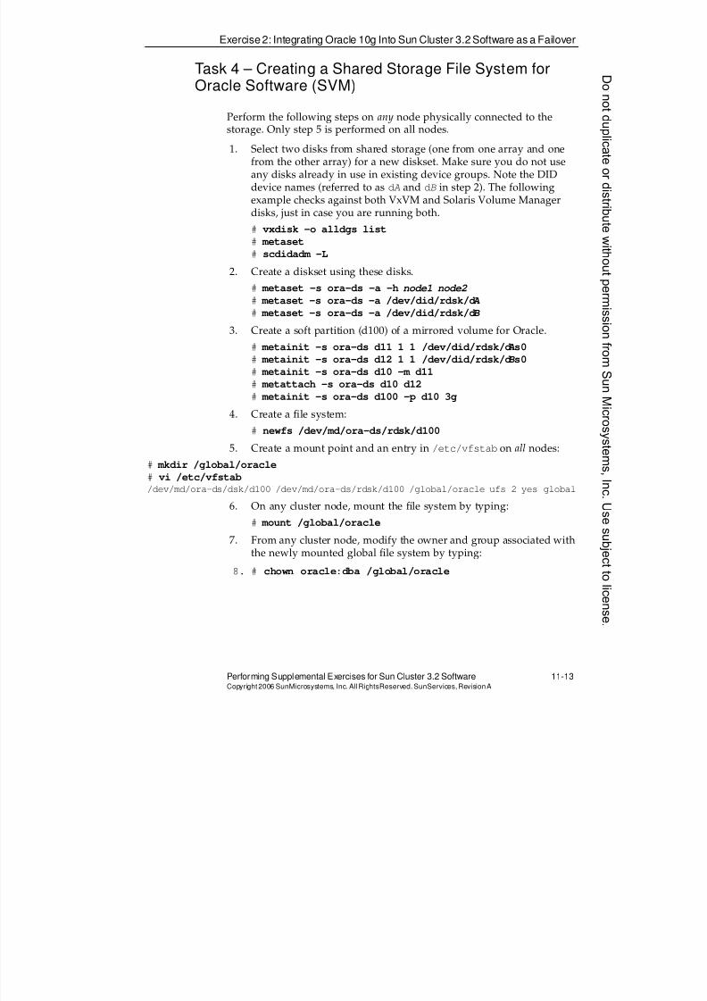
8/4/2019 Sun Cluster 3.2 Administration VC-ES-345
http://slidepdf.com/reader/full/sun-cluster-32-administration-vc-es-345 505/585
Exercise 2: Integrating Oracle 10g Into Sun Cluster 3.2 Software as a Failover
Performing Supplemental Exercises for Sun Cluster 3.2 Software 11-13Copyright2006 SunMicrosystems, Inc. AllRightsReserved. SunServices,RevisionA
Task 4 – Creating a Shared Storage File System forOracle Software (SVM)
Perform the following steps on any node physically connected to the
storage. Only step 5 is performed on all nodes.1. Select two disks from shared storage (one from one array and one
from the other array) for a new diskset. Make sure you do not useany disks already in use in existing device groups. Note the DIDdevice names (referred to as dA and dB in step 2). The followingexample checks against both VxVM and Solaris Volume Managerdisks, just in case you are running both.
# vxdisk -o alldgs list
# metaset
# scdidadm -L
2. Create a diskset using these disks.# metaset -s ora-ds -a -h node1 node2
# metaset -s ora-ds -a /dev/did/rdsk/d A
# metaset -s ora-ds -a /dev/did/rdsk/dB
3. Create a soft partition (d100) of a mirrored volume for Oracle.
# metainit -s ora-ds d11 1 1 /dev/did/rdsk/d A s0
# metainit -s ora-ds d12 1 1 /dev/did/rdsk/dB s0
# metainit -s ora-ds d10 -m d11
# metattach -s ora-ds d10 d12
# metainit -s ora-ds d100 -p d10 3g
4. Create a file system:
# newfs /dev/md/ora-ds/rdsk/d100
5. Create a mount point and an entry in /etc/vfstab on all nodes:
# mkdir /global/oracle
# vi /etc/vfstab/dev/md/ora-ds/dsk/d100 /dev/md/ora-ds/rdsk/d100 /global/oracle ufs 2 yes global
6. On any cluster node, mount the file system by typing:
# mount /global/oracle
7. From any cluster node, modify the owner and group associated withthe newly mounted global file system by typing:
8. # chown oracle:dba /global/oracle
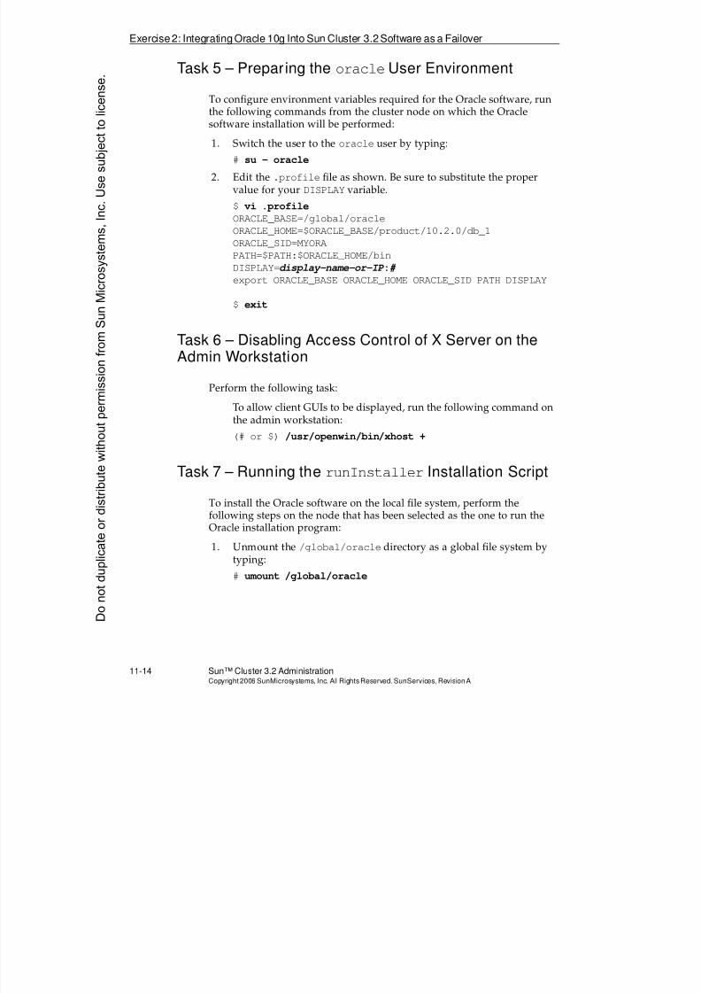
8/4/2019 Sun Cluster 3.2 Administration VC-ES-345
http://slidepdf.com/reader/full/sun-cluster-32-administration-vc-es-345 506/585
Exercise2: Integrating Oracle 10g Into Sun Cluster 3.2Software as a Failover
11-14 Sun™ Cluster 3.2 AdministrationCopyright2006 SunMicrosystems, Inc. AllRights Reserved.SunServices,RevisionA
Task 5 – Preparing the oracleUser Environment
To configure environment variables required for the Oracle software, runthe following commands from the cluster node on which the Oraclesoftware installation will be performed:
1. Switch the user to the oracle user by typing:
# su - oracle
2. Edit the .profile file as shown. Be sure to substitute the propervalue for your DISPLAY variable.
$ vi .profile
ORACLE_BASE=/global/oracle
ORACLE_HOME=$ORACLE_BASE/product/10.2.0/db_1
ORACLE_SID=MYORA
PATH=$PATH:$ORACLE_HOME/bin
DISPLAY=display-name-or-IP :# export ORACLE_BASE ORACLE_HOME ORACLE_SID PATH DISPLAY
$ exit
Task 6 – Disabling Access Control of X Server on theAdmin Workstation
Perform the following task:
To allow client GUIs to be displayed, run the following command onthe admin workstation:
(# or $) /usr/openwin/bin/xhost +
Task 7 – Running the runInstaller Installation Script
To install the Oracle software on the local file system, perform thefollowing steps on the node that has been selected as the one to run theOracle installation program:
1. Unmount the /global/oracle directory as a global file system bytyping:
# umount /global/oracle
Donotduplicate
ordistributewithoutpermissionfrom SunMicrosystems,Inc.Usesubject
tolicense.
8/4/2019 Sun Cluster 3.2 Administration VC-ES-345
http://slidepdf.com/reader/full/sun-cluster-32-administration-vc-es-345 507/585
Exercise 2: Integrating Oracle 10g Into Sun Cluster 3.2 Software as a Failover
Performing Supplemental Exercises for Sun Cluster 3.2 Software 11-15Copyright2006 SunMicrosystems, Inc. AllRightsReserved. SunServices,RevisionA
2. Mount the /global/oracle directory as a nonglobal file systemlocal to the node on which the installation is to be performed. We aredoing this just to speed up the installation.
# mount -o noglobal /global/oracle
Note – If you get a no such device error, the other node is probably stillprimary for the underlying storage. Use cldg switch -n this_node
ora-dg and try to mount again.
3. Switch the user to the oracle user by typing:
# su - oracle
4. Change directory to the location of the Oracle software by typing:
$ cd ORACLE-10gR2-db-software-location
5. Run therunInstaller
script by typing:$ ./runInstaller
6. Respond to the dialogs by using Table 11-1.
Table 11-1 The runInstaller Script Dialog Answers
Dialog Action
Welcome Click Advanced Installation (near the bottom).
[The basic installation makes some wrong choices
for Sun Cluster.]
Click Next.
Specify Inventory Directory andCredentials
Verify and click Next.
Select Installation Type Select the Custom radio button, and click Next.
Specify Home Details Verify and click Next.
[The path is taken from the $ORACLE_HOME that
you set in your profile, so if it looks wrong, youneed to quit it and start again.]
8/4/2019 Sun Cluster 3.2 Administration VC-ES-345
http://slidepdf.com/reader/full/sun-cluster-32-administration-vc-es-345 508/585
Exercise2: Integrating Oracle 10g Into Sun Cluster 3.2Software as a Failover
11-16 Sun™ Cluster 3.2 AdministrationCopyright2006 SunMicrosystems, Inc. AllRights Reserved.SunServices,RevisionA
Available Product Components Deselect the following (so our install goes faster):
q
Enterprise Edition Optionsq Oracle Enterprise Manager Console DB
10.2.0.1.0
q Oracle Programmer 10.2.0.1.0
q Oracle XML Development Kit 10.2.0.1.0
Click Next.
Product Specific PrerequisiteChecks
Most likely, these checks will all succeed, and youwill be moved automatically to the next screen
without having to touch anything.
If you happen to get a warning, click Next, and ifyou get a pop-up warning window, click Yes toproceed.
Privileged Operating SystemGroups
Verify that they both say dba, and click Next.
Create Database Verify that the Create a Database radio button isselected, and click Next.
Summary Verify, and click install.Oracle Net Configuration AssistantWelcome
Verify that the Perform Typical Configurationcheck box is not selected, and click Next.
Listener Configuration, ListenerName
Verify that the Listener name is LISTENER, andclick Next.
Select Protocols Verify that TCP is among the Selected Protocols,and click Next.
TCP/IP Protocol Configuration Verify that the Use the Standard Port Number of1521 radio button is selected, and click Next.
More Listeners Verify that the No radio button is selected, andclick Next.
Listener Configuration Done Click Next.
Naming Methods Configuration Verify that the No, I Do Not Want to ConfigureAdditional Naming Methods radio button isselected, and click Next.
Table 11-1 The runInstaller Script Dialog Answers (Continued)
Dialog Action
Donotduplicate
ordistributewithoutpermissionfrom SunMicrosystems,Inc.Usesubject
tolicense.
8/4/2019 Sun Cluster 3.2 Administration VC-ES-345
http://slidepdf.com/reader/full/sun-cluster-32-administration-vc-es-345 509/585
Exercise 2: Integrating Oracle 10g Into Sun Cluster 3.2 Software as a Failover
Performing Supplemental Exercises for Sun Cluster 3.2 Software 11-17Copyright2006 SunMicrosystems, Inc. AllRightsReserved. SunServices,RevisionA
Done Click Finish.
DBCA Step 1: Database Templates Select the General Purpose radio button, and clickNext.
Step 2: Database Identification Type MYORA in the Global Database Name textfield, observe that it is echoed in the SID textfield, and click Next.
Step 3: Management Options Verify this is not available (because youdeselected the software option earlier), and clickNext.
Step 4: Database Credentials Verify that the Use the Same Password for AllAccounts radio button is selected.
Enter cangetin as the password, and click Next.
Step 5: Storage Options Verify that File System is selected, and click Next.
Step 6: Database File LocationsVerify that Use Common Location is selected, andverify the path. Click Next.
Step 7: Recovery Configuration Uncheck all the boxes, and click Next.
Step 8: Database Content Uncheck Sample Schemas, and click Next.
Step 9: Initialization Parameters On the Memory tab, select the Typical radio button. Change the Percentage to a ridiculouslysmall number (1%).
Click Next and accept the error telling you theminimum memory required. The percentage willautomatically be changed on your form.
Click Next.
Step 10: Database Storage Click Next.
Step 11: Create Options Verify that Create Database is selected, and clickFinish.
Table 11-1 The runInstaller Script Dialog Answers (Continued)
Dialog Action
8/4/2019 Sun Cluster 3.2 Administration VC-ES-345
http://slidepdf.com/reader/full/sun-cluster-32-administration-vc-es-345 510/585
Exercise2: Integrating Oracle 10g Into Sun Cluster 3.2Software as a Failover
11-18 Sun™ Cluster 3.2 AdministrationCopyright2006 SunMicrosystems, Inc. AllRights Reserved.SunServices,RevisionA
Task 8 – Preparing an Oracle Instance for ClusterIntegration
On the same node from which the Oracle software was installed, performthe following steps as indicated to prepare the Oracle instance for SunCluster 3.x software integration:
1. Configure an Oracle user for the fault monitor by typing (as useroracle):
$ sqlplus /nolog
SQL> connect / as sysdba
SQL> create user sc_fm identified by sc_fm;
SQL> grant create session, create table to sc_fm;
SQL> grant select on v_$sysstat to sc_fm;
SQL> alter user sc_fm default tablespace users quota 1m on users;
SQL> quit
Confirmation Verify summary of database creation options,parameters, character sets, and data files, and
click OK.
Note – This might be a good time to take a break.The database configuration assistant takes 15 to20 minutes to complete.
Database Configuration Assistant Click Exit.
Script (setup privileges) Open a terminal window as user root on theinstaller node and run:
/global/oracle/oraInventory/orainstRoot.sh
Now run/global/oracle/product/10.2.0/db_1/root.sh
Accept the default path name for the local bindirectory.
Click OK in the script prompt window.
End of Installation Click Exit and confirm.
Table 11-1 The runInstaller Script Dialog Answers (Continued)
Dialog Action
Donotduplicate
ordistributewithoutpermissionfrom SunMicrosystems,Inc.Usesubject
tolicense.
8/4/2019 Sun Cluster 3.2 Administration VC-ES-345
http://slidepdf.com/reader/full/sun-cluster-32-administration-vc-es-345 511/585
Exercise 2: Integrating Oracle 10g Into Sun Cluster 3.2 Software as a Failover
Performing Supplemental Exercises for Sun Cluster 3.2 Software 11-19Copyright2006 SunMicrosystems, Inc. AllRightsReserved. SunServices,RevisionA
2. Test the new Oracle user account used by the fault monitor by typing(as user oracle):
$ sqlplus sc_fm/sc_fm
SQL> select * from sys.v_$sysstat;
SQL> quit
3. Create a sample table (as user oracle). You can be creative aboutyour data values:
$ sqlplus /nolog
SQL> connect / as sysdba
SQL> create table mytable (Name VARCHAR(20), age NUMBER(4));
SQL> insert into mytable values ('vincent', 14);
SQL> insert into mytable values ('theo', 14);
SQL> commit;
SQL> select * from mytable;
SQL> quit
Note – This sample table is created only for a quick verification that thedatabase is running properly.
4. Shut down the Oracle instance by typing:
$ sqlplus /nolog
SQL> connect / as sysdba
SQL> shutdown
SQL> quit
5. Stop the Oracle listener by typing:$ lsnrctl stop
8/4/2019 Sun Cluster 3.2 Administration VC-ES-345
http://slidepdf.com/reader/full/sun-cluster-32-administration-vc-es-345 512/585
Exercise2: Integrating Oracle 10g Into Sun Cluster 3.2Software as a Failover
11-20 Sun™ Cluster 3.2 AdministrationCopyright2006 SunMicrosystems, Inc. AllRights Reserved.SunServices,RevisionA
6. Configure the Oracle listener by typing (as user oracle):
$ vi $ORACLE_HOME/network/admin/listener.ora
Modify the HOST variable to match logical host name ora-lh.
Add the following lines between the second-to-last and last right
parentheses of the SID_LIST_LISTENER information:(SID_DESC =
(SID_NAME = MYORA)
(ORACLE_HOME = /global/oracle/product/10.2.0/db_1)
(GLOBALDBNAME = MYORA)
)
Your entire file should look identical to the following if your logicalhost name is literally ora-lh:
SID_LIST_LISTENER =
(SID_LIST =
(SID_DESC =(SID_NAME = PLSExtProc)
(ORACLE_HOME = /global/oracle/product/10.2.0/db_1)
(PROGRAM = extproc)
)
(SID_DESC =
(SID_NAME = MYORA)
(ORACLE_HOME = /global/oracle/product/10.2.0/db_1)
(GLOBALDBNAME = MYORA)
)
)
LISTENER =
(DESCRIPTION_LIST =
(DESCRIPTION =
(ADDRESS_LIST =
(ADDRESS = (PROTOCOL = TCP)(HOST = ora-lh)(PORT = 1521))
)
(ADDRESS_LIST =
(ADDRESS = (PROTOCOL = IPC)(KEY = EXTPROC))
)
)
)
7. Configure the tnsnames.ora file by typing (as user oracle):
$ vi $ORACLE_HOME/network/admin/tnsnames.ora
Modify the HOST variables to match logical host name ora-lh.
Donotduplicate
ordistributewithoutpermissionfrom SunMicrosystems,Inc.Usesubject
tolicense.
8/4/2019 Sun Cluster 3.2 Administration VC-ES-345
http://slidepdf.com/reader/full/sun-cluster-32-administration-vc-es-345 513/585
Exercise 2: Integrating Oracle 10g Into Sun Cluster 3.2 Software as a Failover
Performing Supplemental Exercises for Sun Cluster 3.2 Software 11-21Copyright2006 SunMicrosystems, Inc. AllRightsReserved. SunServices,RevisionA
8. Rename the parameter file by typing (as user oracle):
$ cd /global/oracle/admin/MYORA/pfile
$ mv init.ora.* initMYORA.ora
9. Unmount the /global/oraclefile system and remount it using theglobal option (as user root) by typing:
# umount /global/oracle
# mount /global/oracle
Task 9 – Verifying That Oracle Software Runs on OtherNodes
Start the Oracle software on the second node by performing the followingsteps:
1. Configure a virtual interface with the ora-lh IP address by typing:
# ifconfig pubnet-adapter addif ora-lh netmask + broadcast + up
2. Switch the user to oracle user by typing:
# su - oracle
3. Start the Oracle instance by typing:
$ sqlplus /nolog
SQL> connect / as sysdba
SQL> startup
SQL> quit
4. Start the Oracle listener by typing:
$ lsnrctl start
5. Query the database and then shut it down by typing:
$ sqlplus SYS@MYORA as sysdba
Enter Password: cangetin
SQL> select * from mytable;
SQL> shutdown
SQL> quit
6. Stop the Oracle listener by typing:$ lsnrctl stop
7. Remove the virtual interface for ora-lh (as user root) by typing:
# ifconfig pubnet-adapter removeif ora-lh
8. Repeat steps 1–7 on all remaining cluster nodes.
8/4/2019 Sun Cluster 3.2 Administration VC-ES-345
http://slidepdf.com/reader/full/sun-cluster-32-administration-vc-es-345 514/585
Exercise2: Integrating Oracle 10g Into Sun Cluster 3.2Software as a Failover
11-22 Sun™ Cluster 3.2 AdministrationCopyright2006 SunMicrosystems, Inc. AllRights Reserved.SunServices,RevisionA
Task 10 – Registering the SUNW.HAStoragePlusType
Perform the following task:
If necessary (if not done in a previous exercise), register the
SUNW.HAStoragePlus type from any one node in the cluster:# clrt register SUNW.HAStoragePlus
Task 11 – Installing and Registering Oracle DataService
Perform the following steps as indicated to install and register the Oracledata service:
1. Install the data service agent on all nodes:# cd sc32_location/Solaris_sparc/Product
# cd sun_cluster_agents/Solaris_10/Packages
# pkgadd -d . SUNWscor
2. Register the SUNW.oracle_server and SUNW.oracle_listener
resource types from one cluster node by typing:
# clrt register SUNW.oracle_server
# clrt register SUNW.oracle_listener
Task 12 – Creating Resources and Resource Groupsfor Oracle
Perform the following steps from one cluster node to create the resourcegroup and resources necessary for the Oracle data service:
1. Create an empty resource group by typing:
# clrg create -n node1,node2[,node3] ora-rg
2. Create a LogicalHostname resource by typing:
# clrslh create -g ora-rg ora-lh
3. Create an HAStoragePlus resource. Use AffinityOn=false if youhave a nonstorage node configured for the resource group:
# clrs create -g ora-rg -t HAStoragePlus \
-p FilesystemMountPoints=/global/oracle \
-p AffinityOn=[true|false] ora-stor
Donotduplicate
ordistributewithoutpermissionfrom SunMicrosystems,Inc.Usesubject
tolicense.
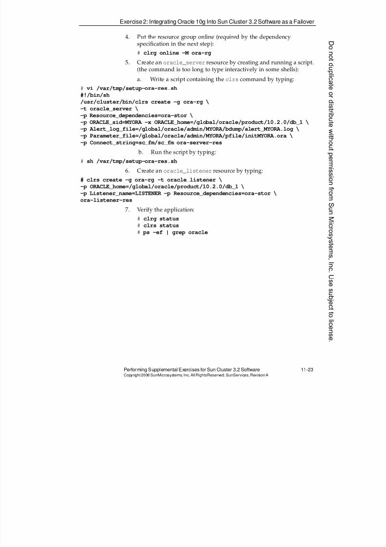
8/4/2019 Sun Cluster 3.2 Administration VC-ES-345
http://slidepdf.com/reader/full/sun-cluster-32-administration-vc-es-345 515/585
Exercise 2: Integrating Oracle 10g Into Sun Cluster 3.2 Software as a Failover
Performing Supplemental Exercises for Sun Cluster 3.2 Software 11-23Copyright2006 SunMicrosystems, Inc. AllRightsReserved. SunServices,RevisionA
4. Put the resource group online (required by the dependencyspecification in the next step):
# clrg online -M ora-rg
5. Create an oracle_server resource by creating and running a script.(the command is too long to type interactively in some shells):
a. Write a script containing the clrs command by typing:
# vi /var/tmp/setup-ora-res.sh
#!/bin/sh
/usr/cluster/bin/clrs create -g ora-rg \
-t oracle_server \
-p Resource_dependencies=ora-stor \
-p ORACLE_sid=MYORA -x ORACLE_home=/global/oracle/product/10.2.0/db_1 \
-p Alert_log_file=/global/oracle/admin/MYORA/bdump/alert_MYORA.log \
-p Parameter_file=/global/oracle/admin/MYORA/pfile/initMYORA.ora \
-p Connect_string=sc_fm/sc_fm ora-server-res
b. Run the script by typing:
# sh /var/tmp/setup-ora-res.sh
6. Create an oracle_listener resource by typing:
# clrs create -g ora-rg -t oracle_listener \
-p ORACLE_home=/global/oracle/product/10.2.0/db_1 \
-p Listener_name=LISTENER -p Resource_dependencies=ora-stor \
ora-listener-res
7. Verify the application:
# clrg status
# clrs status
# ps -ef | grep oracle
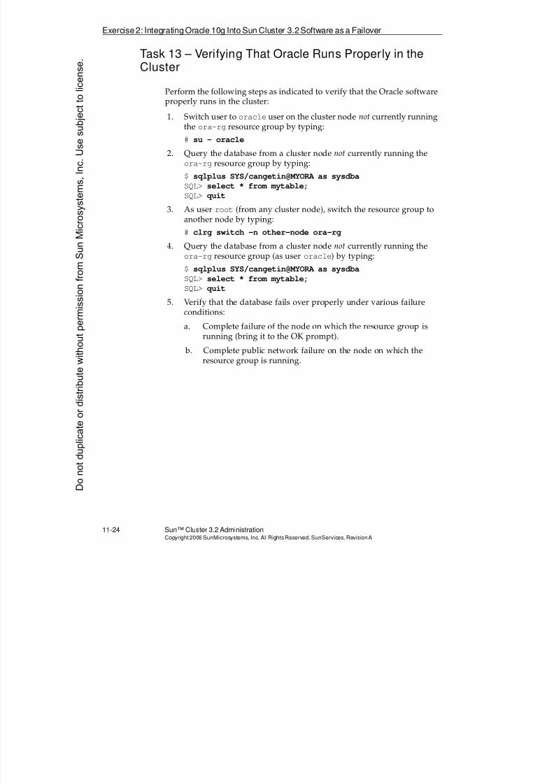
8/4/2019 Sun Cluster 3.2 Administration VC-ES-345
http://slidepdf.com/reader/full/sun-cluster-32-administration-vc-es-345 516/585
Exercise2: Integrating Oracle 10g Into Sun Cluster 3.2Software as a Failover
11-24 Sun™ Cluster 3.2 AdministrationCopyright2006 SunMicrosystems, Inc. AllRights Reserved.SunServices,RevisionA
Task 13 – Verifying That Oracle Runs Properly in theCluster
Perform the following steps as indicated to verify that the Oracle software
properly runs in the cluster:1. Switch user to oracle user on the cluster node not currently running
the ora-rg resource group by typing:
# su - oracle
2. Query the database from a cluster node not currently running theora-rg resource group by typing:
$ sqlplus SYS/cangetin@MYORA as sysdba
SQL> select * from mytable;
SQL> quit
3. As user root (from any cluster node), switch the resource group toanother node by typing:
# clrg switch -n other-node ora-rg
4. Query the database from a cluster node not currently running theora-rg resource group (as user oracle) by typing:
$ sqlplus SYS/cangetin@MYORA as sysdba
SQL> select * from mytable;
SQL> quit
5. Verify that the database fails over properly under various failureconditions:
a. Complete failure of the node on which the resource group isrunning (bring it to the OK prompt).
b. Complete public network failure on the node on which theresource group is running.
Donotduplicate
ordistributewithoutpermissionfrom SunMicrosystems,Inc.Usesubject
tolicense.
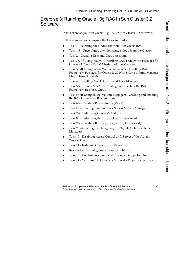
8/4/2019 Sun Cluster 3.2 Administration VC-ES-345
http://slidepdf.com/reader/full/sun-cluster-32-administration-vc-es-345 517/585
Exercise 3: Running Oracle 10g RAC in Sun Cluster 3.2 Software
Performing Supplemental Exercises for Sun Cluster 3.2 Software 11-25Copyright2006 SunMicrosystems, Inc. AllRightsReserved. SunServices,RevisionA
Exercise 3: Running Oracle 10g RAC in Sun Cluster 3.2Software
In this exercise, you run Oracle 10g RAC in Sun Cluster 3.2 software.
In this exercise, you complete the following tasks:
q Task 1 – Selecting the Nodes That Will Run Oracle RAC
q Task 1.5 – Unconfigure any Nonstorage Node From the Cluster
q Task 2 – Creating User and Group Accounts
q Task 3A (If Using VxVM) – Installing RAC Framework Packages forOracle RAC With VxVM Cluster Volume Manager
q Task 3B (If Using Solaris Volume Manager) – Installing RACFramework Packages for Oracle RAC With Solaris Volume ManagerMulti-Owner Disksets
q Task 4 – Installing Oracle Distributed Lock Manager
q Task 5A (If Using VxVM) – Creating and Enabling the RACFramework Resource Group
q Task 5B (If Using Solaris Volume Manager) – Creating and Enablingthe RAC Framework Resource Group
q Task 6A – Creating Raw Volumes (VxVM)
q Task 6B – Creating Raw Volumes (Solaris Volume Manager)
q Task 7 – Configuring Oracle Virtual IPs
q Task 8 – Configuring the oracle User Environment
q Task 9A – Creating the dbca_raw_config File (VxVM)
q Task 9B – Creating the dbca_raw_config File (Solaris VolumeManager)
q Task 10 – Disabling Access Control on X Server of the AdminWorkstation
q Task 11 – Installing Oracle CRS Software
q Respond to the dialog boxes by using Table 11-2.
q Task 12 – Creating Resources and Resource Groups for Oracle
q Task 14 – Verifying That Oracle RAC Works Properly in a Cluster
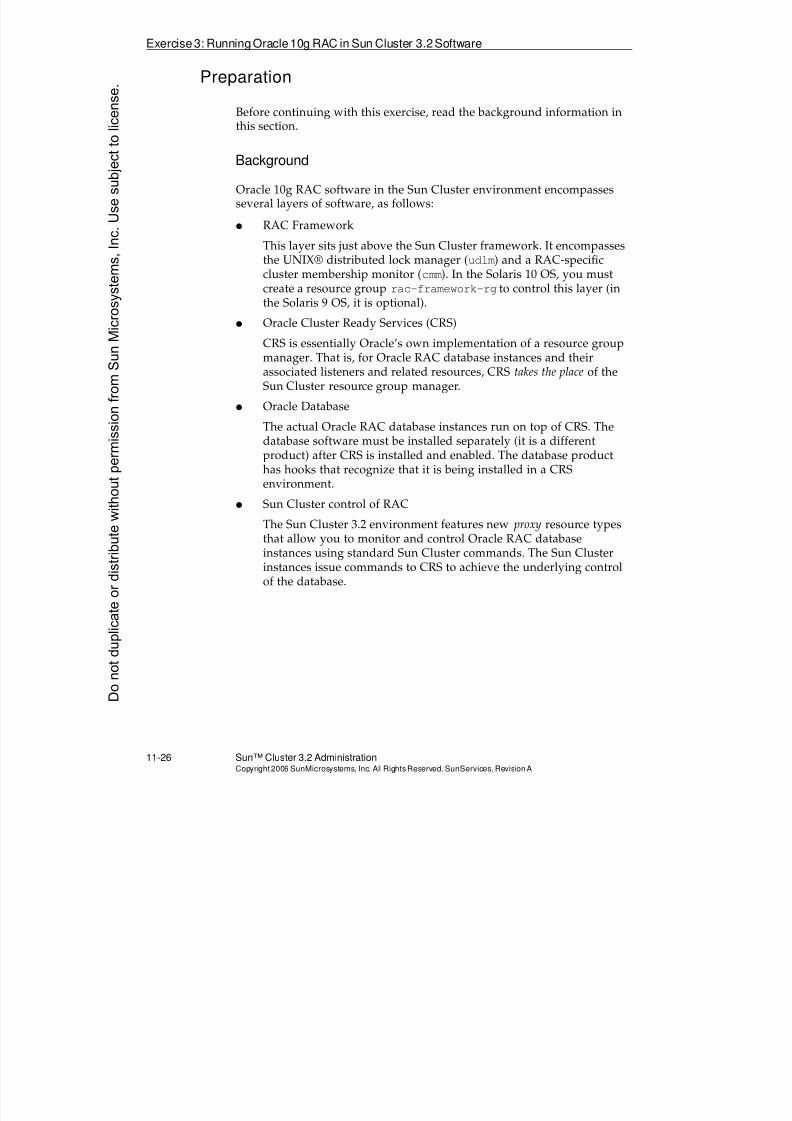
8/4/2019 Sun Cluster 3.2 Administration VC-ES-345
http://slidepdf.com/reader/full/sun-cluster-32-administration-vc-es-345 518/585
Exercise3: RunningOracle10g RAC in Sun Cluster 3.2Software
11-26 Sun™ Cluster 3.2 AdministrationCopyright2006 SunMicrosystems, Inc. AllRights Reserved.SunServices,RevisionA
Preparation
Before continuing with this exercise, read the background information inthis section.
Background
Oracle 10g RAC software in the Sun Cluster environment encompassesseveral layers of software, as follows:
q RAC Framework
This layer sits just above the Sun Cluster framework. It encompassesthe UNIX® distributed lock manager (udlm) and a RAC-specificcluster membership monitor (cmm). In the Solaris 10 OS, you mustcreate a resource group rac-framework-rg to control this layer (in
the Solaris 9 OS, it is optional).q Oracle Cluster Ready Services (CRS)
CRS is essentially Oracle’s own implementation of a resource groupmanager. That is, for Oracle RAC database instances and theirassociated listeners and related resources, CRS takes the place of theSun Cluster resource group manager.
q Oracle Database
The actual Oracle RAC database instances run on top of CRS. Thedatabase software must be installed separately (it is a different
product) after CRS is installed and enabled. The database producthas hooks that recognize that it is being installed in a CRSenvironment.
q Sun Cluster control of RAC
The Sun Cluster 3.2 environment features new proxy resource typesthat allow you to monitor and control Oracle RAC databaseinstances using standard Sun Cluster commands. The Sun Clusterinstances issue commands to CRS to achieve the underlying controlof the database.
Donotduplicate
ordistributewithoutpermissionfrom SunMicrosystems,Inc.Usesubject
tolicense.
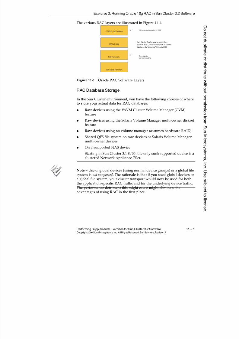
8/4/2019 Sun Cluster 3.2 Administration VC-ES-345
http://slidepdf.com/reader/full/sun-cluster-32-administration-vc-es-345 519/585
Exercise 3: Running Oracle 10g RAC in Sun Cluster 3.2 Software
Performing Supplemental Exercises for Sun Cluster 3.2 Software 11-27Copyright2006 SunMicrosystems, Inc. AllRightsReserved. SunServices,RevisionA
The various RAC layers are illustrated in Figure 11-1.
Figure 11-1 Oracle RAC Software Layers
RAC Database Storage
In the Sun Cluster environment, you have the following choices of whereto store your actual data for RAC databases:
q Raw devices using the VxVM Cluster Volume Manager (CVM)feature
q Raw devices using the Solaris Volume Manager multi-owner disksetfeature
q Raw devices using no volume manager (assumes hardware RAID)
q Shared QFS file system on raw devices or Solaris Volume Managermulti-owner devices
q On a supported NAS device
Starting in Sun Cluster 3.1 8/05, the only such supported device is aclustered Network Appliance Filer.
Note – Use of global devices (using normal device groups) or a global filesystem is not supported. The rationale is that if you used global devices ora global file system, your cluster transport would now be used for both
the application-specific RAC traffic and for the underlying device traffic.The performance detriment this might cause might eliminate theadvantages of using RAC in the first place.
ORACLE RAC Database
ORACLE CRS
RAC Framework
Sun Cluster Framework
DB instances controlled by CRS,
Controlled byrac-framework rg
S u n C l u s t e r R A C p r o x y r e s o u r c e l e t s
y o u u s e S u n C l u s t e r c o m m a n d s t o c o n t r o l
d a t a b a s e b y " p r o x y i n g " t h r o u g h C R S
8/4/2019 Sun Cluster 3.2 Administration VC-ES-345
http://slidepdf.com/reader/full/sun-cluster-32-administration-vc-es-345 520/585
Exercise3: RunningOracle10g RAC in Sun Cluster 3.2Software
11-28 Sun™ Cluster 3.2 AdministrationCopyright2006 SunMicrosystems, Inc. AllRights Reserved.SunServices,RevisionA
In this lab, you can choose to use either VxVM or Solaris VolumeManager. The variations in the lab are indicated by tasks that have an A orB suffix. You will always choose only one such task. When you have builtyour storage devices, there are very few variations in the tasks thatactually install and test the Oracle software.
This lab does not actually address careful planning of your raw devicestorage. In the lab, you create all the volumes using the same pair of disks.
Task 1 – Selecting the Nodes That Will Run OracleRAC
Select the nodes on which the Oracle 10g RAC software will be installedand configured. The nodes you select must all be attached to shared
storage.
Note – All the cluster command examples shown for the rest of the RACexercise assume you have two storage nodes. You can make theappropriate substitutions (in many -n node lists, and in the values ofDesired_primaries and Maximum_primaries properties), if you havemore than two storage nodes on which you choose to install RAC. Thereare some storage volumes that are created on a per-node basis. This will be noted further in the sections where you create your storage volumes.
Donotduplicate
ordistributewithoutpermissionfrom SunMicrosystems,Inc.Usesubject
tolicense.
8/4/2019 Sun Cluster 3.2 Administration VC-ES-345
http://slidepdf.com/reader/full/sun-cluster-32-administration-vc-es-345 521/585
Exercise 3: Running Oracle 10g RAC in Sun Cluster 3.2 Software
Performing Supplemental Exercises for Sun Cluster 3.2 Software 11-29Copyright2006 SunMicrosystems, Inc. AllRightsReserved. SunServices,RevisionA
Task 1.5 – Unconfigure any Nonstorage Node Fromthe Cluster
VxVM’s CVM feature, in particular, is very nasty and kernel-panicky if
you still have nonstorage nodes in the cluster, even if you do not intend touse them for Oracle RAC. Perform the following steps on the indicatednodes if you have a nonstorage node:
1. Reboot the nonstorage node to noncluster mode.
2. On the nonstorage node, edit /etc/vfstab and comment out linescontaining a global filesystem except the line for/global/.devices/node@# (you can leave that one).
3. On one of the nodes remaining in the cluster, type the following toallow the nonstorage node to remove itself:
# claccess allow -h name_of_non_storage_node
# clrg remove-node -n name_of_non_storage_node +
If for some reason you already completed the zones lab in thismodule, and are also attempting this lab, you will need to clean upthe node lists for the apache application like this:
# clrg remove-node -n \
name_of_non_storage_node:myzone sa-rg web-rg
4. On the nonstorage node, type the following to remove itself from thecluster:
# clnode remove -n name_of_any_other_node_remaining
8/4/2019 Sun Cluster 3.2 Administration VC-ES-345
http://slidepdf.com/reader/full/sun-cluster-32-administration-vc-es-345 522/585
Exercise3: RunningOracle10g RAC in Sun Cluster 3.2Software
11-30 Sun™ Cluster 3.2 AdministrationCopyright2006 SunMicrosystems, Inc. AllRights Reserved.SunServices,RevisionA
Task 2 – Creating User and Group Accounts
Perform the following steps on all selected cluster nodes:
Note – If you have already completed the HA-Oracle lab, then delete theoracle user and dba groups from all nodes before proceeding.
1. Create the dba group account by typing:
# groupadd -g 7777 dba
2. Create the oracle user account by typing:
# useradd -g dba -u 7777 -d /oracle -m -s /bin/ksh oracle
3. Provide a password for the oracle user account by typing:
# passwd oracle
New Password: oracleRe-enter new Password: oracle
Task 3A (If Using VxVM) – Installing RAC FrameworkPackages for Oracle RAC With VxVM Cluster VolumeManager
Perform the following steps on all selected cluster nodes
1. Install the appropriate packages from the software location:# cd sc32_location/Solaris_sparc/Product
# cd sun_cluster_agents/Solaris_10/Packages
# pkgadd -d . SUNWscucm SUNWudlm SUNWudlmr SUNWcvm SUNWcvmr SUNWscor
2. Enter a license for the CVM feature of VxVM. Your instructor willtell you from where you can paste a CVM license.
# vxlicinst
3. Verify that you now have a second license for the CVM_FULL feature:
# vxlicrep
4. Refresh the VxVM licenses that are in memory:
# vxdctl license init
Donotduplicate
ordistributewithoutpermissionfrom SunMicrosystems,Inc.Usesubject
tolicense.
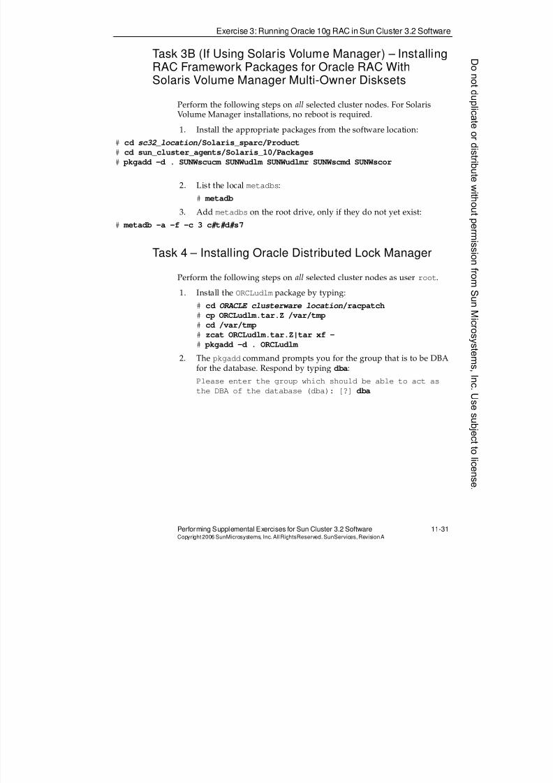
8/4/2019 Sun Cluster 3.2 Administration VC-ES-345
http://slidepdf.com/reader/full/sun-cluster-32-administration-vc-es-345 523/585
Exercise 3: Running Oracle 10g RAC in Sun Cluster 3.2 Software
Performing Supplemental Exercises for Sun Cluster 3.2 Software 11-31Copyright2006 SunMicrosystems, Inc. AllRightsReserved. SunServices,RevisionA
Task 3B (If Using Solaris Volume Manager) – InstallingRAC Framework Packages for Oracle RAC WithSolaris Volume Manager Multi-Owner Disksets
Perform the following steps on all selected cluster nodes. For SolarisVolume Manager installations, no reboot is required.
1. Install the appropriate packages from the software location:
# cd sc32_location/Solaris_sparc/Product
# cd sun_cluster_agents/Solaris_10/Packages
# pkgadd -d . SUNWscucm SUNWudlm SUNWudlmr SUNWscmd SUNWscor
2. List the local metadbs:
# metadb
3. Add metadbs on the root drive, only if they do not yet exist:# metadb -a -f -c 3 c# t# d# s7
Task 4 – Installing Oracle Distributed Lock Manager
Perform the following steps on all selected cluster nodes as user root.
1. Install the ORCLudlm package by typing:
# cd ORACLE_clusterware_location/racpatch
# cp ORCLudlm.tar.Z /var/tmp# cd /var/tmp
# zcat ORCLudlm.tar.Z|tar xf -
# pkgadd -d . ORCLudlm
2. The pkgadd command prompts you for the group that is to be DBAfor the database. Respond by typing dba:
Please enter the group which should be able to act as
the DBA of the database (dba): [?] dba
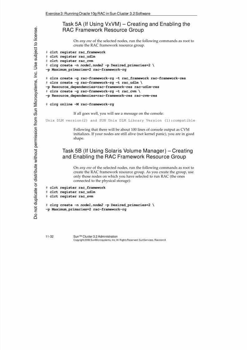
8/4/2019 Sun Cluster 3.2 Administration VC-ES-345
http://slidepdf.com/reader/full/sun-cluster-32-administration-vc-es-345 524/585
Exercise3: RunningOracle10g RAC in Sun Cluster 3.2Software
11-32 Sun™ Cluster 3.2 AdministrationCopyright2006 SunMicrosystems, Inc. AllRights Reserved.SunServices,RevisionA
Task 5A (If Using VxVM) – Creating and Enabling theRAC Framework Resource Group
On any one of the selected nodes, run the following commands as root to
create the RAC framework resource group.# clrt register rac_framework
# clrt register rac_udlm
# clrt register rac_cvm
# clrg create -n node1,node2 -p Desired_primaries=2 \
-p Maximum_primaries=2 rac-framework-rg
# clrs create -g rac-framework-rg -t rac_framework rac-framework-res
# clrs create -g rac-framework-rg -t rac_udlm \
-p Resource_dependencies=rac-framework-res rac-udlm-res
# clrs create -g rac-framework-rg -t rac_cvm \
-p Resource_dependencies=rac-framework-res rac-cvm-res
# clrg online -M rac-framework-rg
If all goes well, you will see a message on the console:
Unix DLM version(2) and SUN Unix DLM Library Version (1):compatible
Following that there will be about 100 lines of console output as CVMinitializes. If your nodes are still alive (not kernel panic), you are in goodshape.
Task 5B (If Using Solaris Volume Manager) – Creatingand Enabling the RAC Framework Resource Group
On any one of the selected nodes, run the following commands as root tocreate the RAC framework resource group. As you create the group, useonly those nodes on which you have selected to run RAC (the onesconnected to the physical storage):
#clrt register rac_framework# clrt register rac_udlm
# clrt register rac_svm
# clrg create -n node1,node2 -p Desired_primaries=2 \
-p Maximum_primaries=2 rac-framework-rg
Donotduplicate
ordistributewithoutpermissionfrom SunMicrosystems,Inc.Usesubject
tolicense.
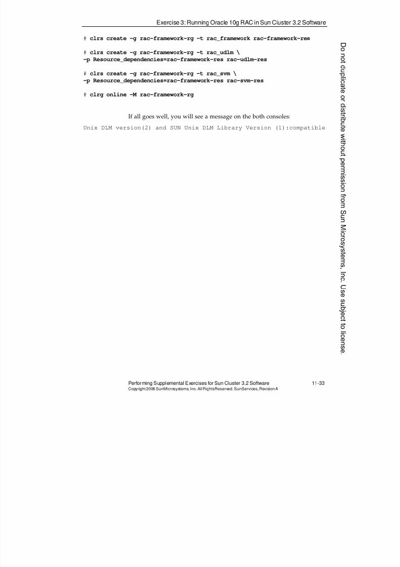
8/4/2019 Sun Cluster 3.2 Administration VC-ES-345
http://slidepdf.com/reader/full/sun-cluster-32-administration-vc-es-345 525/585
Exercise 3: Running Oracle 10g RAC in Sun Cluster 3.2 Software
Performing Supplemental Exercises for Sun Cluster 3.2 Software 11-33Copyright2006 SunMicrosystems, Inc. AllRightsReserved. SunServices,RevisionA
# clrs create -g rac-framework-rg -t rac_framework rac-framework-res
# clrs create -g rac-framework-rg -t rac_udlm \
-p Resource_dependencies=rac-framework-res rac-udlm-res
# clrs create -g rac-framework-rg -t rac_svm \
-p Resource_dependencies=rac-framework-res rac-svm-res
# clrg online -M rac-framework-rg
If all goes well, you will see a message on the both consoles:
Unix DLM version(2) and SUN Unix DLM Library Version (1):compatible
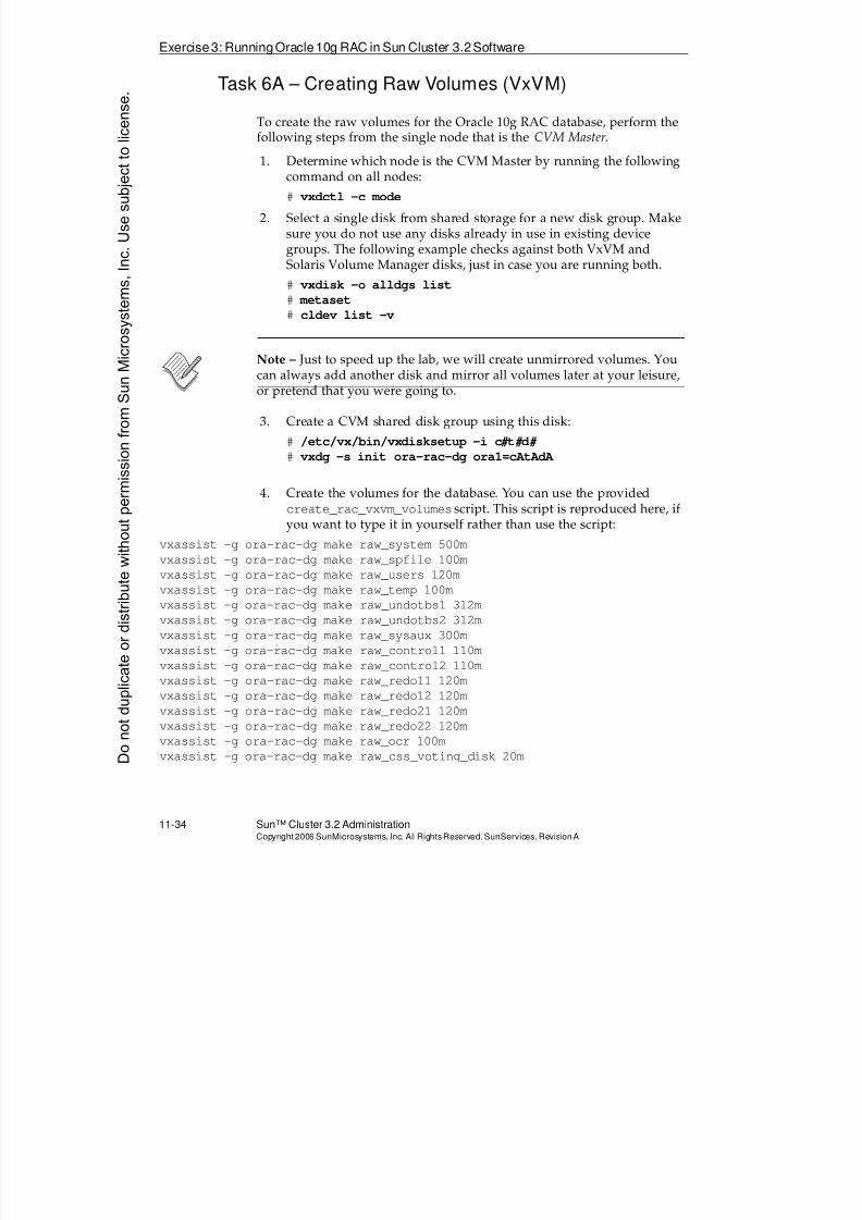
8/4/2019 Sun Cluster 3.2 Administration VC-ES-345
http://slidepdf.com/reader/full/sun-cluster-32-administration-vc-es-345 526/585
Exercise3: RunningOracle10g RAC in Sun Cluster 3.2Software
11-34 Sun™ Cluster 3.2 AdministrationCopyright2006 SunMicrosystems, Inc. AllRights Reserved.SunServices,RevisionA
Task 6A – Creating Raw Volumes (VxVM)
To create the raw volumes for the Oracle 10g RAC database, perform thefollowing steps from the single node that is the CVM Master.
1. Determine which node is the CVM Master by running the followingcommand on all nodes:
# vxdctl -c mode
2. Select a single disk from shared storage for a new disk group. Makesure you do not use any disks already in use in existing devicegroups. The following example checks against both VxVM andSolaris Volume Manager disks, just in case you are running both.
# vxdisk -o alldgs list
# metaset
# cldev list -v
Note – Just to speed up the lab, we will create unmirrored volumes. Youcan always add another disk and mirror all volumes later at your leisure,or pretend that you were going to.
3. Create a CVM shared disk group using this disk:
# /etc/vx/bin/vxdisksetup -i c# t# d#
# vxdg -s init ora-rac-dg ora1=cAtAdA
4. Create the volumes for the database. You can use the providedcreate_rac_vxvm_volumes script. This script is reproduced here, ifyou want to type it in yourself rather than use the script:
vxassist -g ora-rac-dg make raw_system 500m
vxassist -g ora-rac-dg make raw_spfile 100m
vxassist -g ora-rac-dg make raw_users 120m
vxassist -g ora-rac-dg make raw_temp 100m
vxassist -g ora-rac-dg make raw_undotbs1 312m
vxassist -g ora-rac-dg make raw_undotbs2 312m
vxassist -g ora-rac-dg make raw_sysaux 300m
vxassist -g ora-rac-dg make raw_control1 110m
vxassist -g ora-rac-dg make raw_control2 110m
vxassist -g ora-rac-dg make raw_redo11 120m
vxassist -g ora-rac-dg make raw_redo12 120m
vxassist -g ora-rac-dg make raw_redo21 120m
vxassist -g ora-rac-dg make raw_redo22 120m
vxassist -g ora-rac-dg make raw_ocr 100m
vxassist -g ora-rac-dg make raw_css_voting_disk 20mDonotduplicate
ordistributewithoutpermissionfrom SunMicrosystems,Inc.Usesubject
tolicense.
8/4/2019 Sun Cluster 3.2 Administration VC-ES-345
http://slidepdf.com/reader/full/sun-cluster-32-administration-vc-es-345 527/585
Exercise 3: Running Oracle 10g RAC in Sun Cluster 3.2 Software
Performing Supplemental Exercises for Sun Cluster 3.2 Software 11-35Copyright2006 SunMicrosystems, Inc. AllRightsReserved. SunServices,RevisionA
Note – You need to create 3 additional volumes for each additional node(more than 2) that you may be using. For example, for a third node createthe volumes raw_undotbs3 (size 312m), raw_redo13 (120m), andraw_redo23 (120m)
5. Zero out the configuration and voting devices. This eliminatesproblems that might arise from data left over from a previous class:
# dd if=/dev/zero of=/dev/vx/rdsk/ora-rac-dg/raw_ocr bs=16k
# dd if=/dev/zero of=/dev/vx/rdsk/ora-rac-dg/raw_css_voting_disk bs=16k
Note – Do not be concerned with error messages that appear at the end ofrunning the above commands. You will probably get errors indicating thatthe end of the device does not align exactly on a 16K boundary.
6. Change the owner and group associated with the newly createdvolumes (assumes sh or ksh syntax here):
# cd /dev/vx/rdsk/ora-rac-dg
# for vol in *
> do
> vxedit -g ora-rac-dg set user=oracle group=dba $vol
> done
Task 6B – Creating Raw Volumes (Solaris Volume
Manager)
To create the raw volumes for the Oracle 10g RAC database, performsteps 1–5 from any one of the selected cluster nodes. Step 6 is the only stepthat is run on all selected nodes.
1. Select a single disk from shared storage for a new disk set. Make sureyou do not use any disk already in use in existing device groups.Note the device identifier (DID) number of your selected disk(referred to as d# in step 2). The following example checks against both VxVM and Solaris Volume Manager disks, just in case you are
running both.# vxdisk -o alldgs list
# metaset
# cldev list -v
8/4/2019 Sun Cluster 3.2 Administration VC-ES-345
http://slidepdf.com/reader/full/sun-cluster-32-administration-vc-es-345 528/585
Exercise3: RunningOracle10g RAC in Sun Cluster 3.2Software
11-36 Sun™ Cluster 3.2 AdministrationCopyright2006 SunMicrosystems, Inc. AllRights Reserved.SunServices,RevisionA
Note – Just to speed up the lab, we will create unmirrored volumes. Youcan always add another disk and mirror the parent volume later at yourleisure, or pretend that you were going to.
2. Create a multi-owner diskset using this disk.
# metaset -s ora-rac-ds -a -M -h node1 node2
# metaset -s ora-rac-ds -a /dev/did/rdsk/d#
3. Create a big mirror from which to partition all the necessary datavolumes (still call it a mirror although it has only one submirror;then you could easily just add the second half of the mirror later atyour leisure)
# metainit -s ora-rac-ds d11 1 1 /dev/did/rdsk/d# s0
# metainit -s ora-rac-ds d10 -m d11
4. Create the volumes for the database. You can use the providedcreate_rac_svm_volumes script. This script is reproduced here,including the comments indicating which volumes you are creating.The commands are highlighted, if you want to type them in yourselfrather than use the script.
# system volume d100 (500mb)
metainit -s ora-rac-ds d100 -p d10 500m
# spfile volume d101 (100mb)
metainit -s ora-rac-ds d101 -p d10 100m
# users volume d102 (120mb)
metainit -s ora-rac-ds d102 -p d10 120m
# temp volume d103 (100mb)
metainit -s ora-rac-ds d103 -p d10 100m
# undo volume #1 d104 (312mb)
metainit -s ora-rac-ds d104 -p d10 312m
# undo volume #2 d105 (312mb) metainit -s ora-rac-ds d105 -p d10 312m
# sysaux volume d106 (300mb)
metainit -s ora-rac-ds d106 -p d10 300m
# control volume #1 d107 (100mb)
metainit -s ora-rac-ds d107 -p d10 110mDonotduplicate
ordistributewithoutpermissionfrom SunMicrosystems,Inc.Usesubject
tolicense.
8/4/2019 Sun Cluster 3.2 Administration VC-ES-345
http://slidepdf.com/reader/full/sun-cluster-32-administration-vc-es-345 529/585
Exercise 3: Running Oracle 10g RAC in Sun Cluster 3.2 Software
Performing Supplemental Exercises for Sun Cluster 3.2 Software 11-37Copyright2006 SunMicrosystems, Inc. AllRightsReserved. SunServices,RevisionA
# control volume #2 d108 (100mb)
metainit -s ora-rac-ds d108 -p d10 110m
# redo volume #1.1 d109 (120m)
metainit -s ora-rac-ds d109 -p d10 120m
# redo volume #1.2 d110 (120m)
metainit -s ora-rac-ds d110 -p d10 120m
# redo volume #2.1 d111 (120m)
metainit -s ora-rac-ds d111 -p d10 120m
# redo volume #2.2 d112(120m)
metainit -s ora-rac-ds d112 -p d10 120m
# OCR Configuration volume d113 (100mb) metainit -s ora-rac-ds d113 -p d10 100m
# CSS voting disk d114 (20mb)
metainit -s ora-rac-ds d114 -p d10 20m
Note – You need to create 3 additional volumes for each additional node(more than 2) that you may be using. For example, for a third node created115 (312mb) for the undo #3 volume , d116 (120m) for redo #1.3, andd117 (120mb) for redo #2.3.
5. From either node, zero out the configuration and voting devices. Thiseliminates problems that might arise from data left over from aprevious class:
# dd if=/dev/zero of=/dev/md/ora-rac-ds/rdsk/d113 bs=16k
# dd if=/dev/zero of=/dev/md/ora-rac-ds/rdsk/d114 bs=16k
Note – Do not be concerned with error messages that appear at the end of
running the above commands. You will probably get errors indicating thatthe end of the device does not align exactly on a 16K boundary.
6. On all selected nodes, change the owner and group associated with thenewly created volumes.
# chown oracle:dba /dev/md/ora-rac-ds/dsk/*
# chown oracle:dba /dev/md/ora-rac-ds/rdsk/*
8/4/2019 Sun Cluster 3.2 Administration VC-ES-345
http://slidepdf.com/reader/full/sun-cluster-32-administration-vc-es-345 530/585
Exercise3: RunningOracle10g RAC in Sun Cluster 3.2Software
11-38 Sun™ Cluster 3.2 AdministrationCopyright2006 SunMicrosystems, Inc. AllRights Reserved.SunServices,RevisionA
Task 7 – Configuring Oracle Virtual IPs
Configure virtual IPs for use by the Oracle RAC database. Oracle CRScontrols these IPs, failing over both of them to a surviving node if one ofthe nodes crashes. When one of these IPs fails over, Oracle clients do not
successfully contact the database using that IP. Instead, they get a“connection refused” indication, and have their client software set toautomatically try the other IP.
Perform the following task on all selected nodes as root (you can edit thehosts file on one node and copy it over or paste in your entries):
Edit the /etc/hosts file and create public network entries for newvirtual IPs. You will have one IP per node that you are using withOracle RAC. If you use consecutive IP addresses, then theconfiguration assistant in the next task automatically guesses the
second IP when you type in the first. Make sure you do not conflictwith any other physical or logical IPs that you or any other studentshave been using during the week.
# vi /etc/hosts
x.y.z.w nodename1-vip
x.y.z.w+1 nodename2-vip
Donotduplicate
ordistributewithoutpermissionfrom SunMicrosystems,Inc.Usesubject
tolicense.
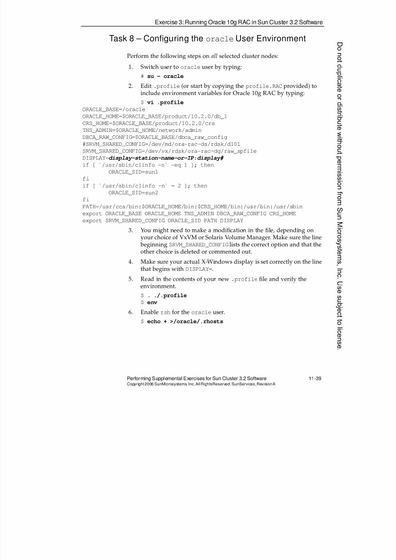
8/4/2019 Sun Cluster 3.2 Administration VC-ES-345
http://slidepdf.com/reader/full/sun-cluster-32-administration-vc-es-345 531/585
Exercise 3: Running Oracle 10g RAC in Sun Cluster 3.2 Software
Performing Supplemental Exercises for Sun Cluster 3.2 Software 11-39Copyright2006 SunMicrosystems, Inc. AllRightsReserved. SunServices,RevisionA
Task 8 – Configuring the oracleUser Environment
Perform the following steps on all selected cluster nodes:
1. Switch user to oracle user by typing:
# su - oracle
2. Edit .profile (or start by copying the profile.RAC provided) toinclude environment variables for Oracle 10g RAC by typing:
$ vi .profile
ORACLE_BASE=/oracle
ORACLE_HOME=$ORACLE_BASE/product/10.2.0/db_1
CRS_HOME=$ORACLE_BASE/product/10.2.0/crs
TNS_ADMIN=$ORACLE_HOME/network/admin
DBCA_RAW_CONFIG=$ORACLE_BASE/dbca_raw_config
#SRVM_SHARED_CONFIG=/dev/md/ora-rac-ds/rdsk/d101
SRVM_SHARED_CONFIG=/dev/vx/rdsk/ora-rac-dg/raw_spfileDISPLAY=display-station-name-or-IP :display#
if [ `/usr/sbin/clinfo -n` -eq 1 ]; then
ORACLE_SID=sun1
fi
if [ `/usr/sbin/clinfo -n` = 2 ]; then
ORACLE_SID=sun2
fi
PATH=/usr/ccs/bin:$ORACLE_HOME/bin:$CRS_HOME/bin:/usr/bin:/usr/sbin
export ORACLE_BASE ORACLE_HOME TNS_ADMIN DBCA_RAW_CONFIG CRS_HOME
export SRVM_SHARED_CONFIG ORACLE_SID PATH DISPLAY
3. You might need to make a modification in the file, depending onyour choice of VxVM or Solaris Volume Manager. Make sure the line beginning SRVM_SHARED_CONFIG lists the correct option and that theother choice is deleted or commented out.
4. Make sure your actual X-Windows display is set correctly on the linethat begins with DISPLAY=.
5. Read in the contents of your new .profile file and verify theenvironment.
$ . ./.profile
$ env
6. Enable rsh for the oracle user.
$ echo + >/oracle/.rhosts
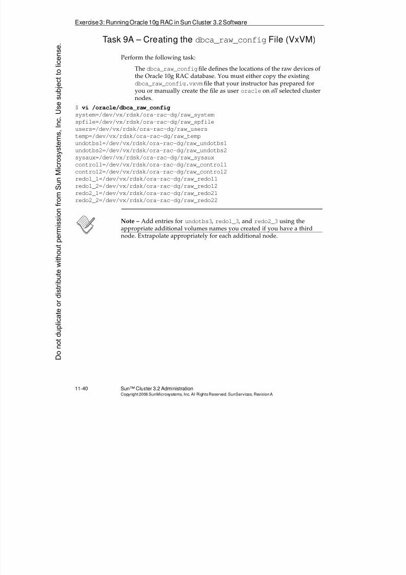
8/4/2019 Sun Cluster 3.2 Administration VC-ES-345
http://slidepdf.com/reader/full/sun-cluster-32-administration-vc-es-345 532/585
Exercise3: RunningOracle10g RAC in Sun Cluster 3.2Software
11-40 Sun™ Cluster 3.2 AdministrationCopyright2006 SunMicrosystems, Inc. AllRights Reserved.SunServices,RevisionA
Task 9A – Creating the dbca_raw_configFile (VxVM)
Perform the following task:
The dbca_raw_configfile defines the locations of the raw devices of
the Oracle 10g RAC database. You must either copy the existingdbca_raw_config.vxvmfile that your instructor has prepared foryou or manually create the file as user oracle on all selected clusternodes.
$ vi /oracle/dbca_raw_config
system=/dev/vx/rdsk/ora-rac-dg/raw_system
spfile=/dev/vx/rdsk/ora-rac-dg/raw_spfile
users=/dev/vx/rdsk/ora-rac-dg/raw_users
temp=/dev/vx/rdsk/ora-rac-dg/raw_temp
undotbs1=/dev/vx/rdsk/ora-rac-dg/raw_undotbs1
undotbs2=/dev/vx/rdsk/ora-rac-dg/raw_undotbs2
sysaux=/dev/vx/rdsk/ora-rac-dg/raw_sysaux
control1=/dev/vx/rdsk/ora-rac-dg/raw_control1
control2=/dev/vx/rdsk/ora-rac-dg/raw_control2
redo1_1=/dev/vx/rdsk/ora-rac-dg/raw_redo11
redo1_2=/dev/vx/rdsk/ora-rac-dg/raw_redo12
redo2_1=/dev/vx/rdsk/ora-rac-dg/raw_redo21
redo2_2=/dev/vx/rdsk/ora-rac-dg/raw_redo22
Note – Add entries for undotbs3, redo1_3, and redo2_3 using theappropriate additional volumes names you created if you have a thirdnode. Extrapolate appropriately for each additional node.
Donotduplicate
ordistributewithoutpermissionfrom SunMicrosystems,Inc.Usesubject
tolicense.
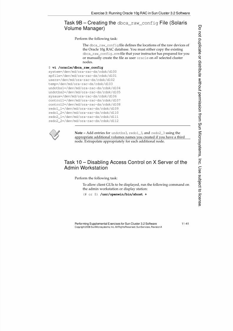
8/4/2019 Sun Cluster 3.2 Administration VC-ES-345
http://slidepdf.com/reader/full/sun-cluster-32-administration-vc-es-345 533/585
Exercise 3: Running Oracle 10g RAC in Sun Cluster 3.2 Software
Performing Supplemental Exercises for Sun Cluster 3.2 Software 11-41Copyright2006 SunMicrosystems, Inc. AllRightsReserved. SunServices,RevisionA
Task 9B – Creating the dbca_raw_configFile (SolarisVolume Manager)
Perform the following task:
The dbca_raw_configfile defines the locations of the raw devices ofthe Oracle 10g RAC database. You must either copy the existingdbca_raw_config.svmfile that your instructor has prepared for youor manually create the file as user oracle on all selected clusternodes.
$ vi /oracle/dbca_raw_config
system=/dev/md/ora-rac-ds/rdsk/d100
spfile=/dev/md/ora-rac-ds/rdsk/d101
users=/dev/md/ora-rac-ds/rdsk/d102
temp=/dev/md/ora-rac-ds/rdsk/d103
undotbs1=/dev/md/ora-rac-ds/rdsk/d104undotbs2=/dev/md/ora-rac-ds/rdsk/d105
sysaux=/dev/md/ora-rac-ds/rdsk/d106
control1=/dev/md/ora-rac-ds/rdsk/d107
control2=/dev/md/ora-rac-ds/rdsk/d108
redo1_1=/dev/md/ora-rac-ds/rdsk/d109
redo1_2=/dev/md/ora-rac-ds/rdsk/d110
redo2_1=/dev/md/ora-rac-ds/rdsk/d111
redo2_2=/dev/md/ora-rac-ds/rdsk/d112
Note – Add entries for undotbs3, redo1_3, and redo2_3 using theappropriate additional volumes names you created if you have a thirdnode. Extrapolate appropriately for each additional node.
Task 10 – Disabling Access Control on X Server of theAdmin Workstation
Perform the following task:To allow client GUIs to be displayed, run the following command onthe admin workstation or display station:
(# or $) /usr/openwin/bin/xhost +
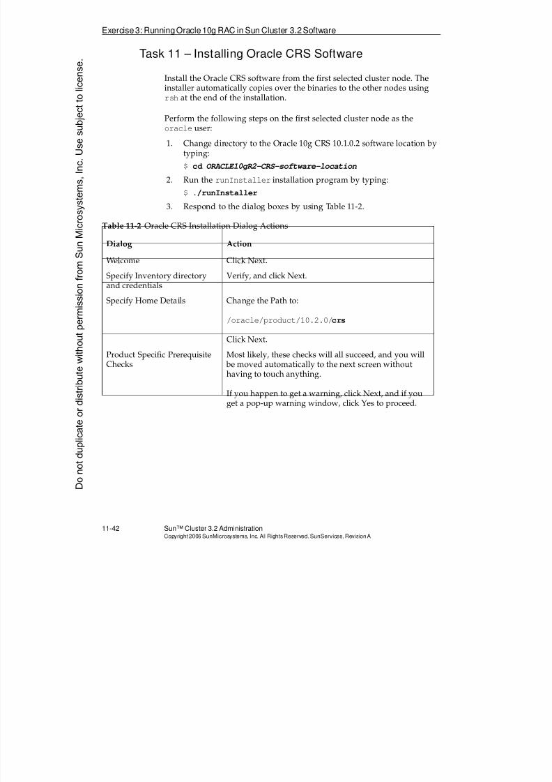
8/4/2019 Sun Cluster 3.2 Administration VC-ES-345
http://slidepdf.com/reader/full/sun-cluster-32-administration-vc-es-345 534/585
Exercise3: RunningOracle10g RAC in Sun Cluster 3.2Software
11-42 Sun™ Cluster 3.2 AdministrationCopyright2006 SunMicrosystems, Inc. AllRights Reserved.SunServices,RevisionA
Task 11 – Installing Oracle CRS Software
Install the Oracle CRS software from the first selected cluster node. Theinstaller automatically copies over the binaries to the other nodes usingrsh at the end of the installation.
Perform the following steps on the first selected cluster node as theoracle user:
1. Change directory to the Oracle 10g CRS 10.1.0.2 software location bytyping:
$ cd ORACLE10gR2-CRS-software-location
2. Run the runInstaller installation program by typing:
$ ./runInstaller
3. Respond to the dialog boxes by using Table 11-2.
Table 11-2 Oracle CRS Installation Dialog Actions
Dialog Action
Welcome Click Next.
Specify Inventory directoryand credentials
Verify, and click Next.
Specify Home Details Change the Path to:
/oracle/product/10.2.0/crs
Click Next.
Product Specific PrerequisiteChecks
Most likely, these checks will all succeed, and you will be moved automatically to the next screen withouthaving to touch anything.
If you happen to get a warning, click Next, and if youget a pop-up warning window, click Yes to proceed.
Donotduplicate
ordistributewithoutpermissionfrom SunMicrosystems,Inc.Usesubject
tolicense.
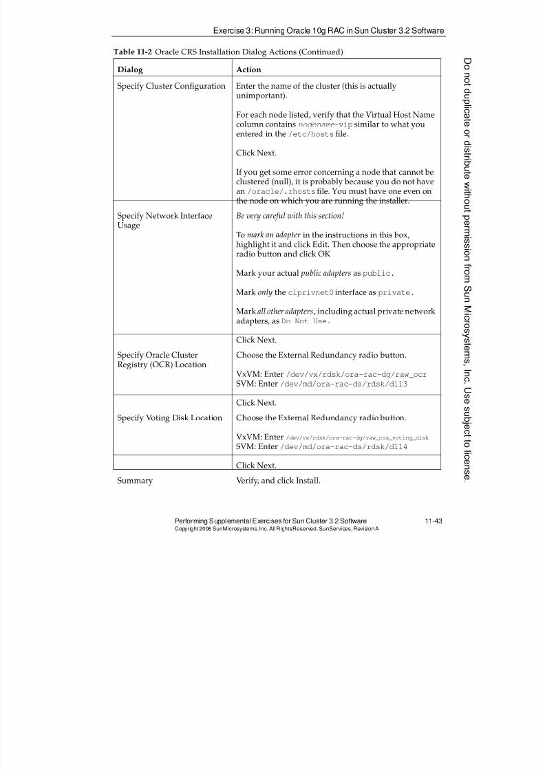
8/4/2019 Sun Cluster 3.2 Administration VC-ES-345
http://slidepdf.com/reader/full/sun-cluster-32-administration-vc-es-345 535/585
Exercise 3: Running Oracle 10g RAC in Sun Cluster 3.2 Software
Performing Supplemental Exercises for Sun Cluster 3.2 Software 11-43Copyright2006 SunMicrosystems, Inc. AllRightsReserved. SunServices,RevisionA
Specify Cluster Configuration Enter the name of the cluster (this is actuallyunimportant).
For each node listed, verify that the Virtual Host Namecolumn contains nodename-vip similar to what youentered in the /etc/hostsfile.
Click Next.
If you get some error concerning a node that cannot beclustered (null), it is probably because you do not havean /oracle/.rhostsfile. You must have one even onthe node on which you are running the installer.
Specify Network InterfaceUsage
Be very careful with this section!
To mark an adapter in the instructions in this box,highlight it and click Edit. Then choose the appropriateradio button and click OK
Mark your actual public adapters as public.
Mark only the clprivnet0 interface as private.
Mark all other adapters, including actual private networkadapters, as Do Not Use.
Click Next.
Specify Oracle ClusterRegistry (OCR) Location
Choose the External Redundancy radio button.
VxVM: Enter /dev/vx/rdsk/ora-rac-dg/raw_ocrSVM: Enter /dev/md/ora-rac-ds/rdsk/d113
Click Next.
Specify Voting Disk Location Choose the External Redundancy radio button.
VxVM: Enter /dev/vx/rdsk/ora-rac-dg/raw_css_voting_disk
SVM: Enter /dev/md/ora-rac-ds/rdsk/d114
Click Next.
Summary Verify, and click Install.
Table 11-2 Oracle CRS Installation Dialog Actions (Continued)
Dialog Action
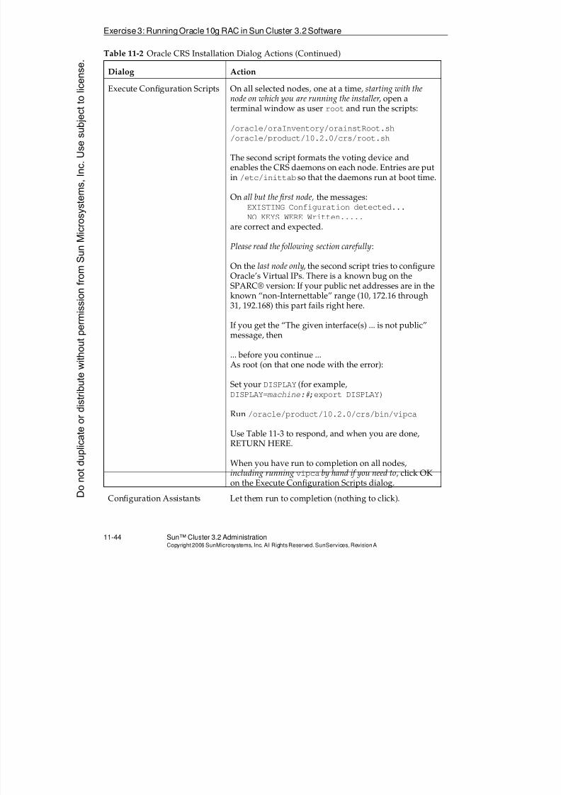
8/4/2019 Sun Cluster 3.2 Administration VC-ES-345
http://slidepdf.com/reader/full/sun-cluster-32-administration-vc-es-345 536/585
Exercise3: RunningOracle10g RAC in Sun Cluster 3.2Software
11-44 Sun™ Cluster 3.2 AdministrationCopyright2006 SunMicrosystems, Inc. AllRights Reserved.SunServices,RevisionA
Execute Configuration Scripts On all selected nodes, one at a time, starting with thenode on which you are running the installer, open a
terminal window as user root and run the scripts:
/oracle/oraInventory/orainstRoot.sh
/oracle/product/10.2.0/crs/root.sh
The second script formats the voting device andenables the CRS daemons on each node. Entries are putin /etc/inittab so that the daemons run at boot time.
On all but the first node, the messages:EXISTING Configuration detected...
NO KEYS WERE Written.....are correct and expected.
Please read the following section carefully:
On the last node only, the second script tries to configureOracle’s Virtual IPs. There is a known bug on theSPARC® version: If your public net addresses are in theknown “non-Internettable” range (10, 172.16 through31, 192.168) this part fails right here.
If you get the “The given interface(s) ... is not public”message, then
... before you continue ...As root (on that one node with the error):
Set your DISPLAY (for example,DISPLAY=machine:#;export DISPLAY)
Run /oracle/product/10.2.0/crs/bin/vipca
Use Table 11-3 to respond, and when you are done,RETURN HERE.
When you have run to completion on all nodes,including running vipca by hand if you need to, click OKon the Execute Configuration Scripts dialog.
Configuration Assistants Let them run to completion (nothing to click).
Table 11-2 Oracle CRS Installation Dialog Actions (Continued)
Dialog Action
Donotduplicate
ordistributewithoutpermissionfrom SunMicrosystems,Inc.Usesubject
tolicense.
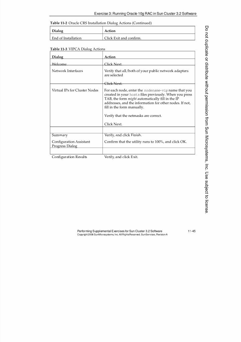
8/4/2019 Sun Cluster 3.2 Administration VC-ES-345
http://slidepdf.com/reader/full/sun-cluster-32-administration-vc-es-345 537/585
Exercise 3: Running Oracle 10g RAC in Sun Cluster 3.2 Software
Performing Supplemental Exercises for Sun Cluster 3.2 Software 11-45Copyright2006 SunMicrosystems, Inc. AllRightsReserved. SunServices,RevisionA
End of Installation Click Exit and confirm.
Table 11-3 VIPCA Dialog Actions
Dialog Action
Welcome Click Next.
Network Interfaces Verify that all/both of your public network adaptersare selected
Click Next.
Virtual IPs for Cluster Nodes For each node, enter the nodename-vip name that youcreated in your hostsfiles previously. When you pressTAB, the form might automatically fill in the IPaddresses, and the information for other nodes. If not,fill in the form manually.
Verify that the netmasks are correct.
Click Next.
Summary Verify, and click Finish.
Configuration AssistantProgress Dialog
Confirm that the utility runs to 100%, and click OK.
Configuration Results Verify, and click Exit.
Table 11-2 Oracle CRS Installation Dialog Actions (Continued)
Dialog Action
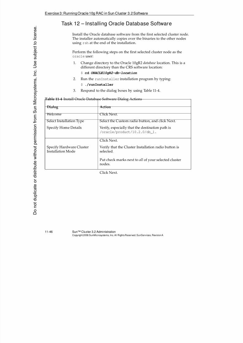
8/4/2019 Sun Cluster 3.2 Administration VC-ES-345
http://slidepdf.com/reader/full/sun-cluster-32-administration-vc-es-345 538/585
Exercise3: RunningOracle10g RAC in Sun Cluster 3.2Software
11-46 Sun™ Cluster 3.2 AdministrationCopyright2006 SunMicrosystems, Inc. AllRights Reserved.SunServices,RevisionA
Task 12 – Installing Oracle Database Software
Install the Oracle database software from the first selected cluster node.The installer automatically copies over the binaries to the other nodesusing rsh at the end of the installation.
Perform the following steps on the first selected cluster node as theoracle user:
1. Change directory to the Oracle 10gR2 database location. This is adifferent directory than the CRS software location:
$ cd ORACLE10gR2-db-location
2. Run the runInstaller installation program by typing:
$ ./runInstaller
3. Respond to the dialog boxes by using Table 11-4.
Table 11-4 Install Oracle Database Software Dialog Actions
Dialog Action
Welcome Click Next.
Select Installation Type Select the Custom radio button, and click Next.
Specify Home Details Verify, especially that the destination path is/oracle/product/10.2.0/db_1.
Click Next.
Specify Hardware ClusterInstallation Mode
Verify that the Cluster Installation radio button isselected.
Put check marks next to all of your selected clusternodes.
Click Next.
Donotduplicate
ordistributewithoutpermissionfrom SunMicrosystems,Inc.Usesubject
tolicense.
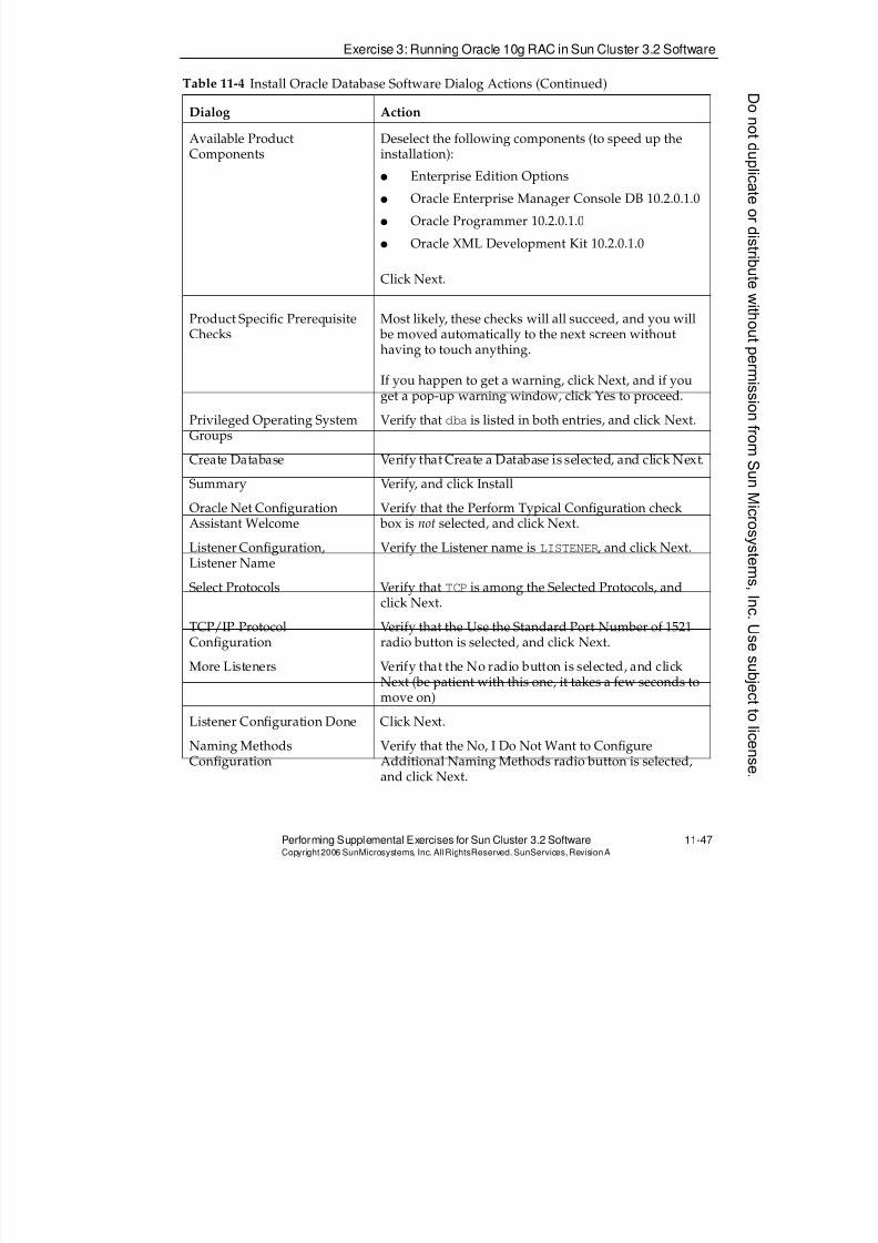
8/4/2019 Sun Cluster 3.2 Administration VC-ES-345
http://slidepdf.com/reader/full/sun-cluster-32-administration-vc-es-345 539/585
Exercise 3: Running Oracle 10g RAC in Sun Cluster 3.2 Software
Performing Supplemental Exercises for Sun Cluster 3.2 Software 11-47Copyright2006 SunMicrosystems, Inc. AllRightsReserved. SunServices,RevisionA
Available ProductComponents
Deselect the following components (to speed up theinstallation):
q Enterprise Edition Options
q Oracle Enterprise Manager Console DB 10.2.0.1.0
q Oracle Programmer 10.2.0.1.0
q Oracle XML Development Kit 10.2.0.1.0
Click Next.
Product Specific Prerequisite
Checks
Most likely, these checks will all succeed, and you will
be moved automatically to the next screen withouthaving to touch anything.
If you happen to get a warning, click Next, and if youget a pop-up warning window, click Yes to proceed.
Privileged Operating SystemGroups
Verify that dba is listed in both entries, and click Next.
Create Database Verify that Create a Database is selected, and click Next.
Summary Verify, and click Install
Oracle Net ConfigurationAssistant Welcome
Verify that the Perform Typical Configuration check box is not selected, and click Next.
Listener Configuration,Listener Name
Verify the Listener name is LISTENER, and click Next.
Select Protocols Verify that TCP is among the Selected Protocols, andclick Next.
TCP/IP ProtocolConfiguration
Verify that the Use the Standard Port Number of 1521radio button is selected, and click Next.
More Listeners Verify that the No radio button is selected, and clickNext (be patient with this one, it takes a few seconds tomove on)
Listener Configuration Done Click Next.
Naming MethodsConfiguration
Verify that the No, I Do Not Want to ConfigureAdditional Naming Methods radio button is selected,and click Next.
Table 11-4 Install Oracle Database Software Dialog Actions (Continued)
Dialog Action
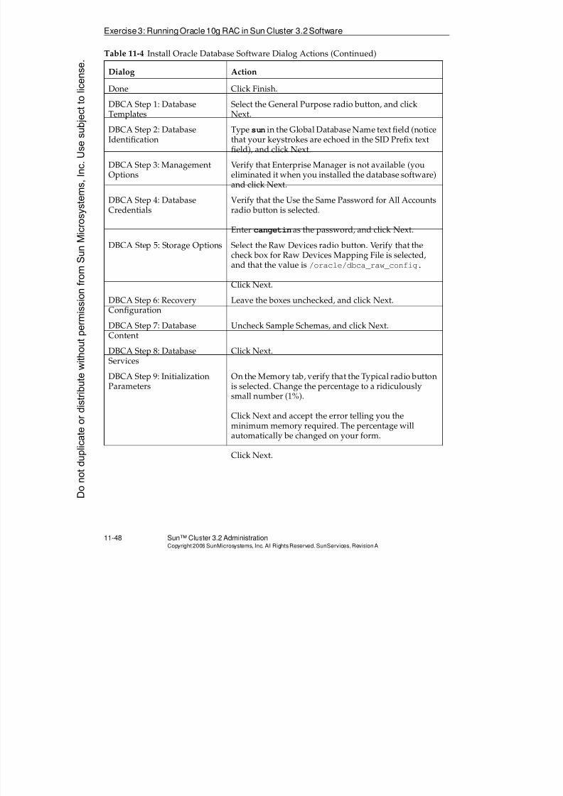
8/4/2019 Sun Cluster 3.2 Administration VC-ES-345
http://slidepdf.com/reader/full/sun-cluster-32-administration-vc-es-345 540/585
Exercise3: RunningOracle10g RAC in Sun Cluster 3.2Software
11-48 Sun™ Cluster 3.2 AdministrationCopyright2006 SunMicrosystems, Inc. AllRights Reserved.SunServices,RevisionA
Done Click Finish.
DBCA Step 1: DatabaseTemplates Select the General Purpose radio button, and clickNext.
DBCA Step 2: DatabaseIdentification
Type sun in the Global Database Name text field (noticethat your keystrokes are echoed in the SID Prefix textfield), and click Next.
DBCA Step 3: ManagementOptions
Verify that Enterprise Manager is not available (youeliminated it when you installed the database software)and click Next.
DBCA Step 4: DatabaseCredentials
Verify that the Use the Same Password for All Accountsradio button is selected.
Enter cangetin as the password, and click Next.
DBCA Step 5: Storage Options Select the Raw Devices radio button. Verify that thecheck box for Raw Devices Mapping File is selected,and that the value is /oracle/dbca_raw_config.
Click Next.
DBCA Step 6: RecoveryConfiguration
Leave the boxes unchecked, and click Next.
DBCA Step 7: DatabaseContent
Uncheck Sample Schemas, and click Next.
DBCA Step 8: DatabaseServices
Click Next.
DBCA Step 9: InitializationParameters
On the Memory tab, verify that the Typical radio buttonis selected. Change the percentage to a ridiculouslysmall number (1%).
Click Next and accept the error telling you the
minimum memory required. The percentage willautomatically be changed on your form.
Click Next.
Table 11-4 Install Oracle Database Software Dialog Actions (Continued)
Dialog Action
Donotduplicate
ordistributewithoutpermissionfrom SunMicrosystems,Inc.Usesubject
tolicense.
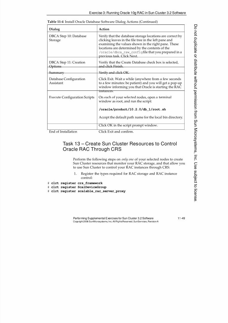
8/4/2019 Sun Cluster 3.2 Administration VC-ES-345
http://slidepdf.com/reader/full/sun-cluster-32-administration-vc-es-345 541/585
Exercise 3: Running Oracle 10g RAC in Sun Cluster 3.2 Software
Performing Supplemental Exercises for Sun Cluster 3.2 Software 11-49Copyright2006 SunMicrosystems, Inc. AllRightsReserved. SunServices,RevisionA
Task 13 – Create Sun Cluster Resources to ControlOracle RAC Through CRS
Perform the following steps on only one of your selected nodes to createSun Cluster resources that monitor your RAC storage, and that allow youto use Sun Cluster to control your RAC instances through CRS:
1. Register the types required for RAC storage and RAC instancecontrol:
# clrt register crs_framework
# clrt register ScalDeviceGroup
# clrt register scalable_rac_server_proxy
DBCA Step 10: DatabaseStorage
Verify that the database storage locations are correct byclicking leaves in the file tree in the left pane and
examining the values shown in the right pane. Theselocations are determined by the contents of the/oracle/dbca_raw_configfile that you prepared in aprevious task. Click Next.
DBCA Step 11: CreationOptions
Verify that the Create Database check box is selected,and click Finish.
Summary Verify and click OK.
Database ConfigurationAssistant
Click Exit. Wait a while (anywhere from a few secondsto a few minutes: be patient) and you will get a pop-up
window informing you that Oracle is starting the RACinstances.
Execute Configuration Scripts On each of your selected nodes, open a terminalwindow as root, and run the script:
/oracle/product/10.2.0/db_1/root.sh
Accept the default path name for the local bin directory.
Click OK in the script prompt window.
End of Installation Click Exit and confirm.
Table 11-4 Install Oracle Database Software Dialog Actions (Continued)
Dialog Action
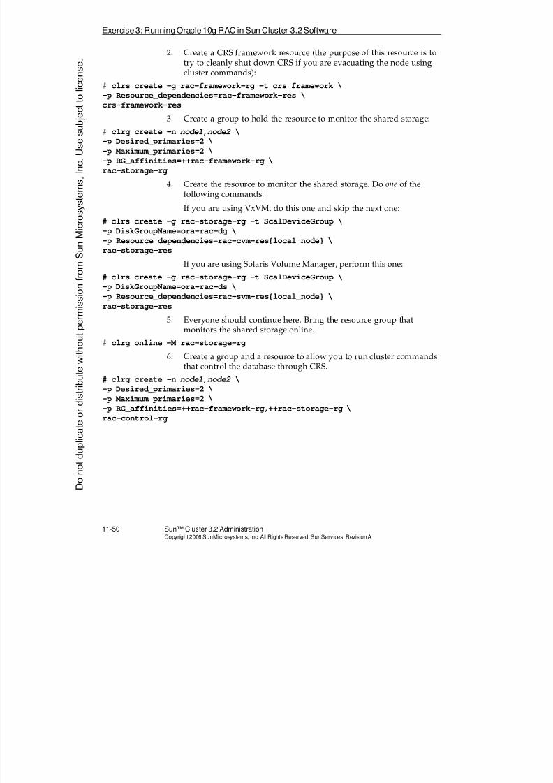
8/4/2019 Sun Cluster 3.2 Administration VC-ES-345
http://slidepdf.com/reader/full/sun-cluster-32-administration-vc-es-345 542/585
Exercise3: RunningOracle10g RAC in Sun Cluster 3.2Software
11-50 Sun™ Cluster 3.2 AdministrationCopyright2006 SunMicrosystems, Inc. AllRights Reserved.SunServices,RevisionA
2. Create a CRS framework resource (the purpose of this resource is totry to cleanly shut down CRS if you are evacuating the node usingcluster commands):
# clrs create -g rac-framework-rg -t crs_framework \
-p Resource_dependencies=rac-framework-res \
crs-framework-res
3. Create a group to hold the resource to monitor the shared storage:
# clrg create -n node1,node2 \
-p Desired_primaries=2 \
-p Maximum_primaries=2 \
-p RG_affinities=++rac-framework-rg \
rac-storage-rg
4. Create the resource to monitor the shared storage. Do one of thefollowing commands:
If you are using VxVM, do this one and skip the next one:# clrs create -g rac-storage-rg -t ScalDeviceGroup \
-p DiskGroupName=ora-rac-dg \
-p Resource_dependencies=rac-cvm-res{local_node} \
rac-storage-res
If you are using Solaris Volume Manager, perform this one:
# clrs create -g rac-storage-rg -t ScalDeviceGroup \
-p DiskGroupName=ora-rac-ds \
-p Resource_dependencies=rac-svm-res{local_node} \
rac-storage-res
5. Everyone should continue here. Bring the resource group thatmonitors the shared storage online.
# clrg online -M rac-storage-rg
6. Create a group and a resource to allow you to run cluster commandsthat control the database through CRS.
# clrg create -n node1,node2 \
-p Desired_primaries=2 \
-p Maximum_primaries=2 \
-p RG_affinities=++rac-framework-rg,++rac-storage-rg \
rac-control-rg
Donotduplicate
ordistributewithoutpermissionfrom SunMicrosystems,Inc.Usesubject
tolicense.
8/4/2019 Sun Cluster 3.2 Administration VC-ES-345
http://slidepdf.com/reader/full/sun-cluster-32-administration-vc-es-345 543/585
Exercise 3: Running Oracle 10g RAC in Sun Cluster 3.2 Software
Performing Supplemental Exercises for Sun Cluster 3.2 Software 11-51Copyright2006 SunMicrosystems, Inc. AllRightsReserved. SunServices,RevisionA
Note – For the following command, make sure you understand whichnode has node id 1, which has node id 2, and so forth, so that you matchcorrectly with the names of the database sub-instances. You can useclinfo -n to verify the node id on each node.
# vi /var/tmp/cr_rac_control
clrs create -g rac-control-rg -t scalable_rac_server_proxy \
-p DB_NAME=sun \
-p ORACLE_SID{name_of_node1}=sun1 \
-p ORACLE_SID{name_of_node2}=sun2 \
-p ORACLE_home=/oracle/product/10.2.0/db_1 \
-p Crs_home=/oracle/product/10.2.0/crs \
-p Resource_dependencies_offline_restart=rac-storage-res{local_node} \
-p Resource_dependencies=rac-framework-res \
rac-control-res
# sh /var/tmp/cr_rac_control
# clrg online -M rac-control-rg
8/4/2019 Sun Cluster 3.2 Administration VC-ES-345
http://slidepdf.com/reader/full/sun-cluster-32-administration-vc-es-345 544/585
Exercise3: RunningOracle10g RAC in Sun Cluster 3.2Software
11-52 Sun™ Cluster 3.2 AdministrationCopyright2006 SunMicrosystems, Inc. AllRights Reserved.SunServices,RevisionA
Task 14 – Verifying That Oracle RAC Works Properly ina Cluster
Run the following commands as indicated to verify that the Oracle
software properly runs in the cluster:
Note – So that the flow of the following task makes sense, make sure youunderstand which node has node id 1, which has node id 2, and so forth.
1. Switch user to the oracle user by typing (all selected cluster nodes):
# su - oracle
2. On node 1, connect to database sub-instance sun1 and create a table.
$ sqlplus SYS@sun1 as sysdba
Enter password: cangetin
SQL> create table mytable (Name VARCHAR(20), age NUMBER(4));
SQL> insert into mytable values ('vincent', 14);
SQL> insert into mytable values ('theo', 14);
SQL> commit;
SQL> select * from mytable;
SQL> quit
3. From the other node, query the other database sub-instance andverify that the data is there:
$ sqlplus SYS@sun2 as sysdba
Enter password: cangetin
SQL> select * from mytable;
SQL> quit
4. On either node, take advantage of the Sun Cluster control resource touse Sun Cluster commands to shut down the database on one of thenodes (the resource accomplishes the actual control through CRS).
# clrs disable -n node2 rac-control-res
5. On the node for which you shutdown Oracle, verify as the oracle
user that the instance is unavailable:$ crs_stat -t
$ sqlplus SYS@sun2 as sysdba
Enter password: cangetin
6. On either node, reenable the instance through the Sun Clusterresource:D
onotduplicate
ordistributewithoutpermissionfrom SunMicrosystems,Inc.Usesubject
tolicense.
8/4/2019 Sun Cluster 3.2 Administration VC-ES-345
http://slidepdf.com/reader/full/sun-cluster-32-administration-vc-es-345 545/585
Exercise 3: Running Oracle 10g RAC in Sun Cluster 3.2 Software
Performing Supplemental Exercises for Sun Cluster 3.2 Software 11-53Copyright2006 SunMicrosystems, Inc. AllRightsReserved. SunServices,RevisionA
# clrs enable -n node2 rac-control-res
7. On that (affected node), you should be able to repeat step 5. It mighttake a few attempts before the database is initialized and you cansuccessfully access your data.
8. Cause a crash of node 1:
# <Control-]>
telnet> send break
9. On the surviving node, you should see (after 45 seconds or so), theCRS-controlled virtual IP for the crashed node migrate to thesurviving node. Run the following as user oracle:
$ crs_stat -t|grep vip
ora.node2.vip application ONLINE ONLINE node2
ora.node1.vip application ONLINE ONLINE node2
10. While this virtual IP has failed over, verify that there is actually nofailover listener controlled by Oracle CRS. This virtual IP fails overmerely so a client quickly gets a TCP disconnect without having towait for a long time-out. Client software then has a client-side optionto fail over to the other instance.
$ sqlplus SYS@sun1 as sysdba
SQL*Plus: Release 10.2.0.1.0 - Production on Tue May 24
10:56:18 2005
Copyright (c) 1982, 2005, ORACLE. All rights reserved.
Enter password:
ERROR:
ORA-12541: TNS:no listener
Enter user-name: ^D
11. Boot the node that you had halted, by typing boot or go at the OKprompt in the console. If you choose the latter, the node will panicand reboot.
12. After the node boots, monitor the automatic recovery of the virtualIP, the listener, and the database instance by typing, as user oracle,on the surviving node:
$ crs_stat -t
$ /usr/cluster/bin/clrs status

8/4/2019 Sun Cluster 3.2 Administration VC-ES-345
http://slidepdf.com/reader/full/sun-cluster-32-administration-vc-es-345 546/585
It can take several minutes for the full recovery. Keep repeating thesteps.
13. Verify the proper operation of the Oracle database by contacting thevarious sub-instances as the user oracle on the various nodes:
$ sqlplus SYS@sun1 as sysdba
Enter password: cangetin
SQL> select * from mytable;
SQL> quit
Donotduplicate
ordistributewithoutpermissionfrom SunMicrosystems,Inc.Usesubject
tolicense.
8/4/2019 Sun Cluster 3.2 Administration VC-ES-345
http://slidepdf.com/reader/full/sun-cluster-32-administration-vc-es-345 547/585
Exercise Summary
Performing Supplemental Exercises for Sun Cluster 3.2 Software 11-55Copyright2006 SunMicrosystems, Inc. AllRightsReserved. SunServices,RevisionA
Exercise Summary
?
!
Discussion – Take a few minutes to discuss what experiences, issues, ordiscoveries you had during the lab exercises.
q Experiences
q Interpretations
q Conclusions
q Applications

8/4/2019 Sun Cluster 3.2 Administration VC-ES-345
http://slidepdf.com/reader/full/sun-cluster-32-administration-vc-es-345 548/585
Do not duplicate or distribute without permission from Sun Microsystems, Inc. U
8/4/2019 Sun Cluster 3.2 Administration VC-ES-345
http://slidepdf.com/reader/full/sun-cluster-32-administration-vc-es-345 549/585
A-1Copyright2006 SunMicrosystems, Inc. AllRights Reserved.SunServices,RevisionA
Appendix A
Terminal Concentrator
This appendix describes the configuration of the Sun™ TerminalConcentrator (TC) as a remote connection mechanism to the serialconsoles of the nodes in the Sun Cluster software environment.
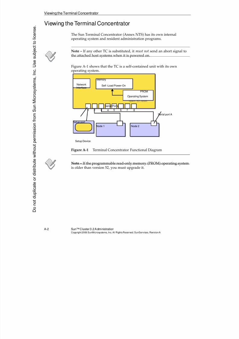
8/4/2019 Sun Cluster 3.2 Administration VC-ES-345
http://slidepdf.com/reader/full/sun-cluster-32-administration-vc-es-345 550/585
Viewing the Terminal Concentrator
A-2 Sun™Cluster 3 .2AdministrationCopyright2006 SunMicrosystems, Inc. AllRights Reserved.SunServices,RevisionA
Viewing the Terminal Concentrator
The Sun Terminal Concentrator (Annex NTS) has its own internaloperating system and resident administration programs.
Note – If any other TC is substituted, it must not send an abort signal tothe attached host systems when it is powered on.
Figure A-1 shows that the TC is a self-contained unit with its ownoperating system.
Figure A-1 Terminal Concentrator Functional Diagram
Note – If the programmable read-only memory (PROM) operating systemis older than version 52, you must upgrade it.
Setup port
Setup Device
Serial port A
Node 1 Node 2
Memory
Self -Load Power-On
Operating System
PROM
oper.52.enet
NetworkInterface
Serial Ports
1 2 3 4 5 6 7 8
Donotduplicate
ordistributewithoutpermissionfrom SunMicrosystems,Inc.Usesubject
tolicense.
8/4/2019 Sun Cluster 3.2 Administration VC-ES-345
http://slidepdf.com/reader/full/sun-cluster-32-administration-vc-es-345 551/585
Viewing the Terminal Concentrator
Terminal Concentrator A-3Copyright2006 SunMicrosystems, Inc. AllRightsReserved. SunServices,RevisionA
Operating System Load
You can set up the TC to load its operating system either internally fromthe resident PROM or externally from a server. In the cluster application,it is always set to load internally. Placing the operating system on an
external server can decrease the reliability of the terminal server.
When power is first applied to the TC, it performs the following steps:
1. It runs a PROM-based self-test and displays error codes.
2. It loads a resident PROM-based operating system into the TCmemory.
Setup Port
Serial port 1 on the TC is a special purpose port that is used only duringinitial setup. It is used primarily to set up the IP address and loadsequence of the TC. You can access port 1 from either a tip connection orfrom a locally connected terminal.
Terminal Concentrator Setup Programs
You must configure the TC nonvolatile random access memory (NVRAM)with the appropriate IP address, boot path, and serial port information.Use the following resident programs to specify this information:
q addr
q seq
q image
q admin
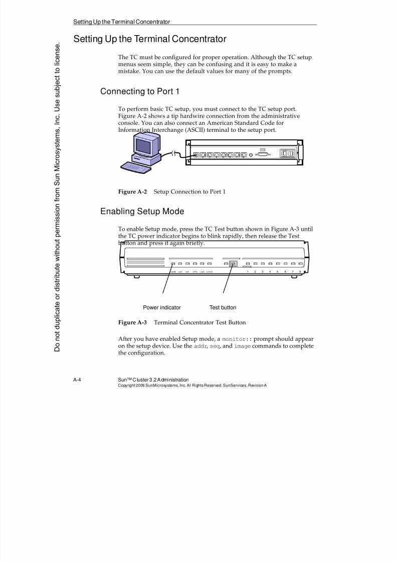
8/4/2019 Sun Cluster 3.2 Administration VC-ES-345
http://slidepdf.com/reader/full/sun-cluster-32-administration-vc-es-345 552/585
Setting Up the Terminal Concentrator
A-4 Sun™Cluster 3 .2AdministrationCopyright2006 SunMicrosystems, Inc. AllRights Reserved.SunServices,RevisionA
Setting Up the Terminal Concentrator
The TC must be configured for proper operation. Although the TC setupmenus seem simple, they can be confusing and it is easy to make amistake. You can use the default values for many of the prompts.
Connecting to Port 1
To perform basic TC setup, you must connect to the TC setup port.Figure A-2 shows a tip hardwire connection from the administrativeconsole. You can also connect an American Standard Code forInformation Interchange (ASCII) terminal to the setup port.
Figure A-2 Setup Connection to Port 1
Enabling Setup Mode
To enable Setup mode, press the TC Test button shown in Figure A-3 untilthe TC power indicator begins to blink rapidly, then release the Test button and press it again briefly.
Figure A-3 Terminal Concentrator Test Button
After you have enabled Setup mode, a monitor:: prompt should appearon the setup device. Use the addr, seq, and image commands to completethe configuration.
1 2 3 4 5 6 7 8
STATUS
1 2 3 4 5 6 7 8POWER UNIT NET ATTN LOAD ACTIVE
Power indicator Test button
Donotduplicate
ordistributewithoutpermissionfrom SunMicrosystems,Inc.Usesubject
tolicense.
8/4/2019 Sun Cluster 3.2 Administration VC-ES-345
http://slidepdf.com/reader/full/sun-cluster-32-administration-vc-es-345 553/585
Setting Up theTerminal Concentrator
Terminal Concentrator A-5Copyright2006 SunMicrosystems, Inc. AllRightsReserved. SunServices,RevisionA
Setting the Terminal Concentrator IP Address
The following example shows how to use the addr program to set the IPaddress of the TC. Usually this is set correctly when your cluster arrives, but you should always verify that it is correct.
monitor:: addr
Enter Internet address [192.9.22.98]:: 129.150.182.100
Enter Subnet mask [255.255.255.0]::
Enter Preferred load host Internet address
[192.9.22.98]:: 129.150.182.100
Enter Broadcast address [0.0.0.0]:: 129.150.182.255
Enter Preferred dump address [192.9.22.98]::
129.150.182.100
Select type of IP packet encapsulation
(ieee802/ethernet) [<ethernet>]::
Type of IP packet encapsulation: <ethernet>
Load Broadcast Y/N [Y]:: y
Setting the Terminal Concentrator Load Source
The following example shows how to use the seq program to specify thetype of loading mechanism to be used:
monitor:: seq
Enter a list of 1 to 4 interfaces to attempt to use fordownloading code or upline dumping. Enter them in the
order they should be tried, separated by commas or
spaces. Possible interfaces are:
Ethernet: net
SELF: self
Enter interface sequence [self]::
The self response configures the TC to load its operating system
internally from the PROM when you turn on the power. The PROM imageis currently called oper.52.enet.
Enabling the self-load feature negates other setup parameters that refer toan external load host and dump host, but you must still define theseparameters during the initial setup sequence.
8/4/2019 Sun Cluster 3.2 Administration VC-ES-345
http://slidepdf.com/reader/full/sun-cluster-32-administration-vc-es-345 554/585
Setting Up the Terminal Concentrator
A-6 Sun™Cluster 3 .2AdministrationCopyright2006 SunMicrosystems, Inc. AllRights Reserved.SunServices,RevisionA
Note – Although you can load the TC’s operating system from an externalserver, this introduces an additional layer of complexity that is prone tofailure.
Specifying the Operating System Image
Even though the self-load mode of operation negates the use of anexternal load and dump device, you should still verify the operatingsystem image name as shown by the following:
monitor:: image
Enter Image name ["oper.52.enet"]::
Enter TFTP Load Directory ["9.2.7/"]::
Enter TFTP Dump path/filename["dump.129.150.182.100"]::
monitor::
Note – Do not define a dump or load address that is on another network because you receive additional questions about a gateway address. If youmake a mistake, you can press Control-C to abort the setup and startagain.
Setting the Serial Port Variables
The TC port settings must be correct for proper cluster operation. Thisincludes the type and mode port settings. Port 1 requires different typeand mode settings. You should verify the port settings before installing thecluster host software. The following is an example of the entire procedure:
admin-ws# telnet terminal_concentrator_name
Trying terminal concentrator IP address ...
Connected to terminal concentrator IP address.Escape character is '^]'.
Rotaries Defined:
cli -
Enter Annex port name or number: cli
Annex Command Line Interpreter * Copyright 1991
Xylogics, Inc.
annex: suDonotduplicate
ordistributewithoutpermissionfrom SunMicrosystems,Inc.Usesubject
tolicense.
8/4/2019 Sun Cluster 3.2 Administration VC-ES-345
http://slidepdf.com/reader/full/sun-cluster-32-administration-vc-es-345 555/585
Setting Up theTerminal Concentrator
Terminal Concentrator A-7Copyright2006 SunMicrosystems, Inc. AllRightsReserved. SunServices,RevisionA
Password: type the password
annex# admin
Annex administration MICRO-XL-UX R7.0.1, 8 ports
admin: show port=1 type mode
Port 1:
type: hardwired mode: cli
admin:set port=1 type hardwired mode cli
admin:set port=2-8 type dial_in mode slave
admin:set port=1-8 imask_7bits Y
admin: quit
annex# boot
bootfile: <CR>
warning: <CR>
Note – Do not perform this procedure through the special setup port; use
public network access.
Setting the Port Password
An optional and recommended security feature is to set per portpasswords. These provides an extra password challenge as you access aserial port in slave mode remotely through the telnet command.
You can set different (or the same) port passwords on each port. You mustset the enable_security parameter to Y to enable all the passwords.
If you ever forget a port password but know the TC root password, youcan just reset the passwords to whatever you want.
admin-ws# telnet terminal_concentrator_name
Trying terminal concentrator IP address . . .
Connected to terminal concentrator IP address.
Escape character is '^]'.
Rotaries Defined:
cli -Enter Annex port name or number: cli
Annex Command Line Interpreter * Copyright 1991
Xylogics, Inc.
annex: su
Password: type the password
annex# admin
Annex administration MICRO-XL-UX R7.0.1, 8 ports
8/4/2019 Sun Cluster 3.2 Administration VC-ES-345
http://slidepdf.com/reader/full/sun-cluster-32-administration-vc-es-345 556/585
Setting Up the Terminal Concentrator
A-8 Sun™Cluster 3 .2AdministrationCopyright2006 SunMicrosystems, Inc. AllRights Reserved.SunServices,RevisionA
admin: set port=2 port_password homer
admin: set port=3 port_password marge
admin: reset 2-3
admin: set annex enable_security Y
admin: reset annex security
Donotduplicate
ordistributewithoutpermissionfrom SunMicrosystems,Inc.Usesubject
tolicense.
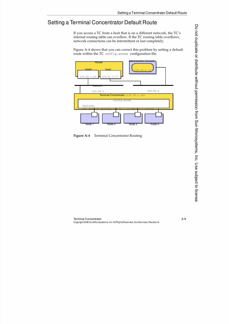
8/4/2019 Sun Cluster 3.2 Administration VC-ES-345
http://slidepdf.com/reader/full/sun-cluster-32-administration-vc-es-345 557/585
Setting a Terminal Concentrator Default Route
Terminal Concentrator A-9Copyright2006 SunMicrosystems, Inc. AllRightsReserved. SunServices,RevisionA
Setting a Terminal Concentrator Default Route
If you access a TC from a host that is on a different network, the TC’sinternal routing table can overflow. If the TC routing table overflows,network connections can be intermittent or lost completely.
Figure A-4 shows that you can correct this problem by setting a defaultroute within the TC config.annex configuration file.
Figure A-4 Terminal Concentrator Routing
Node 2Node 1 Node 3 Node 4
RouterAdministrative Console
Network
hme0 hme1
129.50.1.23 129.50.2.17
129.50.1 129.50.2
Terminal Concentrator (129.50.1.35)
%gateway
net default gateway 129.50.1.23 metric 1 active
config.annex
129.50.2.12
8/4/2019 Sun Cluster 3.2 Administration VC-ES-345
http://slidepdf.com/reader/full/sun-cluster-32-administration-vc-es-345 558/585
Setting a Terminal Concentrator Default Route
A-10 Sun™ Cluster 3.2 AdministrationCopyright2006 SunMicrosystems, Inc. AllRights Reserved.SunServices,RevisionA
Creating a Terminal Concentrator Default Route
To create a default route for the TC, you must edit an electrically erasableprogrammable read-only memory (EEPROM) file in the TC namedconfig.annex. You must also disable the TC routing function. The
following is a summary of the general process:
admin-ws# telnet tc1.central
Trying 129.50.1.35 ...
Connected to 129.50.1.35.
Escape character is ’^]’.
[Return] [Return]
Enter Annex port name or number: cli
...
annex: su
Password: root_password
annex# edit config.annex(Editor starts)
Ctrl-W:save and exit Ctrl-X:exit Ctrl-F:page down
Ctrl-B:page up
%gateway
net default gateway 129.50.1.23 metric 1 active ^W
annex# admin set annex routed n
You may need to reset the appropriate port, Annex
subsystem or reboot the Annex for changes to take
effect.
annex# boot
Note – You must enter an IP routing address appropriate for your site.While the TC is rebooting, the node console connections are not available.
Donotduplicate
ordistributewithoutpermissionfrom SunMicrosystems,Inc.Usesubject
tolicense.
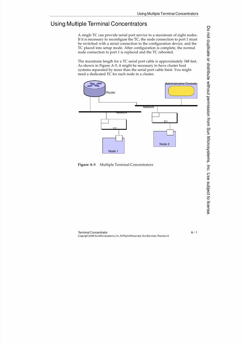
8/4/2019 Sun Cluster 3.2 Administration VC-ES-345
http://slidepdf.com/reader/full/sun-cluster-32-administration-vc-es-345 559/585
Using Multiple Terminal Concentrators
Terminal Concentrator A-11Copyright2006 SunMicrosystems, Inc. AllRightsReserved. SunServices,RevisionA
Using Multiple Terminal Concentrators
A single TC can provide serial port service to a maximum of eight nodes.If it is necessary to reconfigure the TC, the node connection to port 1 must be switched with a serial connection to the configuration device, and theTC placed into setup mode. After configuration is complete, the normalnode connection to port 1 is replaced and the TC rebooted.
The maximum length for a TC serial port cable is approximately 348 feet.As shown in Figure A-5, it might be necessary to have cluster hostsystems separated by more than the serial port cable limit. You mightneed a dedicated TC for each node in a cluster.
Figure A-5 Multiple Terminal Concentrators
Node 2
Node 1
Router
Administrative Console
TC
TC
Network
Network
8/4/2019 Sun Cluster 3.2 Administration VC-ES-345
http://slidepdf.com/reader/full/sun-cluster-32-administration-vc-es-345 560/585
Troubleshooting Terminal Concentrators
A-12 Sun™ Cluster 3.2 AdministrationCopyright2006 SunMicrosystems, Inc. AllRights Reserved.SunServices,RevisionA
Troubleshooting Terminal Concentrators
Occasionally, it is useful to be able to manually manipulate the TC. Thecommands to do this are not well documented in the cluster manuals.
Using the telnetCommand to Manually Connect to aNode
If the cconsole tool is not using the TC serial ports, you can use thetelnet command to connect to a specific serial port as follows:
# telnet tc_name 5002
You can then log in to the node attached to port 5002. After you have
finished and logged out of the node, you must break the telnetconnection with the Control-] keyboard sequence and then type quit. Ifyou do not, the serial port remains locked and cannot be used by otherapplications, such as the cconsole tool.
Using the telnetCommand to Abort a Node
If you have to abort a cluster node, you can either use the telnet
command to connect directly to the node and use the Control-] keyboardsequence, or you can use the Control-] keyboard sequence in a clusterconsole window. When you have the telnet prompt, you can abort thenode with the following command:
telnet > send brk
ok
Note – You might have to repeat the command multiple times.
Donotduplicate
ordistributewithoutpermissionfrom SunMicrosystems,Inc.Usesubject
tolicense.

8/4/2019 Sun Cluster 3.2 Administration VC-ES-345
http://slidepdf.com/reader/full/sun-cluster-32-administration-vc-es-345 561/585
Troubleshooting Terminal Concentrators
Terminal Concentrator A-13Copyright2006 SunMicrosystems, Inc. AllRightsReserved. SunServices,RevisionA
Connecting to the Terminal ConcentratorCommand-Line Interpreter
You can use the telnet command to connect directly to the TC, and then
use the resident command-line interface (CLI) to perform status andadministration procedures.
# telnet IPaddress
Trying 129.146.241.135...
Connected to 129.146.241.135
Escape character is '^]'.
Enter Annex port name or number: cli
Annex Command Line Interpreter * Copyright 1991
Xylogics, Inc.
annex:
Using the Terminal Concentrator helpCommand
After you connect directly into a terminal concentrator, you can get onlinehelp as follows:
annex: help
annex: help hangup
Identifying and Resetting a Locked Port
If a node crashes, it can leave a telnet session active that effectively locksthe port from further use. You can use the who command to identify whichport is locked, and then use the admin program to reset the locked port.The command sequence is as follows:
annex: who
annex: su
Password:
annex# admin
Annex administration MICRO-XL-UX R7.0.1, 8 ports
admin : reset 6
admin : quit
annex# hangup
8/4/2019 Sun Cluster 3.2 Administration VC-ES-345
http://slidepdf.com/reader/full/sun-cluster-32-administration-vc-es-345 562/585
Troubleshooting Terminal Concentrators
A-14 Sun™ Cluster 3.2 AdministrationCopyright2006 SunMicrosystems, Inc. AllRights Reserved.SunServices,RevisionA
Erasing Terminal Concentrator Settings
Using the TC erase command can be dangerous. Use it only when youhave forgotten the superuser password. It returns all settings to theirdefault values. When the addr command is then run to give the TC its IP
address, the password will be set to this IP. For security reasons, theerase command is available only through the port 1 interface. A typicalprocedure is as follows:
monitor :: erase
1) EEPROM(i.e. Configuration information)
2) FLASH(i.e. Self boot image)
Enter 1 or 2 :: 1
Caution – Do not use option 2 of the erase command; it destroys the TC boot PROM-resident operating system.
Donotduplicate
ordistributewithoutpermissionfrom SunMicrosystems,Inc.Usesubject
tolicense.
8/4/2019 Sun Cluster 3.2 Administration VC-ES-345
http://slidepdf.com/reader/full/sun-cluster-32-administration-vc-es-345 563/585
B-1Copyright2006 SunMicrosystems, Inc. AllRights Reserved.SunServices,RevisionA
Appendix B
ConfiguringMulti-InitiatorSCSI
This appendix contains information that can be used to configuremulti-initiator Small Computer System Interface (SCSI) storage devices,including the Sun StorEdge™ MultiPack desktop array and the SunStorEdge D1000 array.
8/4/2019 Sun Cluster 3.2 Administration VC-ES-345
http://slidepdf.com/reader/full/sun-cluster-32-administration-vc-es-345 564/585
Multi-Initiator Overview
B-2 Sun™Cluster 3 .2AdministrationCopyright2006 SunMicrosystems, Inc. AllRights Reserved.SunServices,RevisionA
Multi-Initiator Overview
This section applies only to SCSI storage devices and not to Fibre Channelstorage used for the multihost disks.
In a stand-alone server, the server node controls the SCSI bus activitiesusing the SCSI host adapter circuit connecting this server to a particularSCSI bus. This SCSI host adapter circuit is referred to as the SCSI initiator.This circuit initiates all bus activities for this SCSI bus. The default SCSIaddress of SCSI host adapters in Sun™ systems is 7.
Cluster configurations share storage between multiple server nodes.When the cluster storage consists of singled-ended or differential SCSIdevices, the configuration is referred to as multi-initiator SCSI . As thisterminology implies, more than one SCSI initiator exists on the SCSI bus.
The SCSI specification requires that each device on a SCSI bus have aunique SCSI address. (The host adapter is also a device on the SCSI bus.)The default hardware configuration in a multi-initiator environmentresults in a conflict because all SCSI host adapters default to 7.
To resolve this conflict, on each SCSI bus leave one of the SCSI hostadapters with the SCSI address of 7, and set the other host adapters tounused SCSI addresses. Proper planning dictates that these “unused”SCSI addresses include both currently and eventually unused addresses.An example of addresses unused in the future is the addition of storage
by installing new drives into empty drive slots. In most configurations,the available SCSI address for a second host adapter is 6.
You can change the selected SCSI addresses for these host adapters bysetting the scsi-initiator-idOpenBoot™ PROM property. You can setthis property globally for a node or on a per host adapter basis.Instructions for setting a unique scsi-initiator-id for each SCSI hostadapter are included in the chapter for each disk enclosure in Sun™Cluster Hardware Guides.
Donotduplicate
ordistributewithoutpermissionfrom SunMicrosystems,Inc.Usesubject
tolicense.
8/4/2019 Sun Cluster 3.2 Administration VC-ES-345
http://slidepdf.com/reader/full/sun-cluster-32-administration-vc-es-345 565/585
Installing a Sun StorEdge Multipack Device
Configuring Multi-Initiator SCSI B-3Copyright2006 SunMicrosystems, Inc. AllRightsReserved. SunServices,RevisionA
Installing a Sun StorEdge Multipack Device
This section provides the procedure for an initial installation of aSun StorEdge MultiPack device.
Use this procedure to install a Sun StorEdge MultiPack device in a clusterprior to installing the Solaris™ Operating System and Sun™ Clustersoftware. Perform this procedure with the procedures in Sun Cluster 3.2Installation Guide and your server hardware manual.
1. Ensure that each device in the SCSI chain has a unique SCSI address.
The default SCSI address for host adapters is 7. Reserve SCSI address7 for one host adapter in the SCSI chain. This procedure refers to thehost adapter you choose for SCSI address 7 as the host adapter onthe second node. To avoid conflicts, in step 7 you change the
scsi-initiator-idof the remaining host adapter in the SCSI chainto an available SCSI address. This procedure refers to the hostadapter with an available SCSI address as the host adapter on thefirst node. Depending on the device and configuration settings of thedevice, either SCSI address 6 or 8 is usually available.
Caution – Even though a slot in the device might not be in use, youshould avoid setting scsi-initiator-id for the first node to the SCSIaddress for that disk slot. This precaution minimizes future complicationsif you install additional disk drives.
For more information, refer to OpenBoot™ 3.x Command Reference Manualand the labels inside the storage device.
2. Install the host adapters in the nodes that will be connected to thedevice.
For the procedure on installing host adapters, refer to the documentationthat shipped with your nodes.
3. Connect the cables to the device, as shown in Figure B-1 on page B-4.
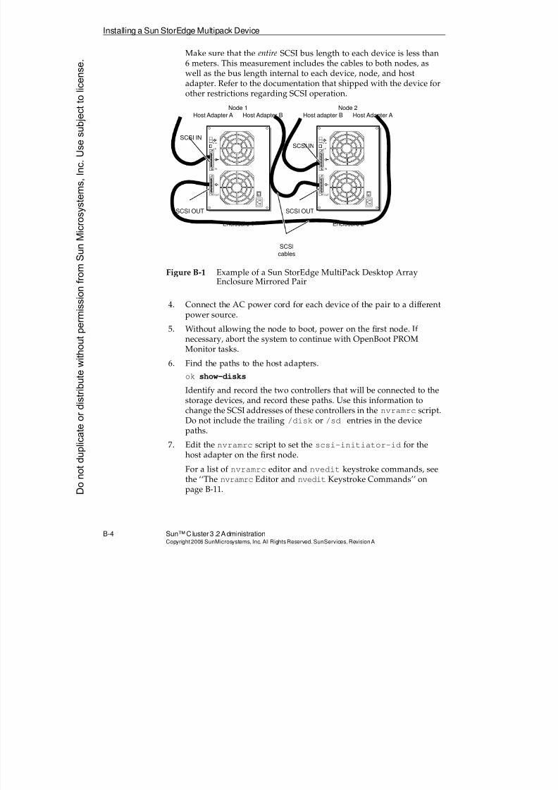
8/4/2019 Sun Cluster 3.2 Administration VC-ES-345
http://slidepdf.com/reader/full/sun-cluster-32-administration-vc-es-345 566/585
Installing a Sun StorEdge Multipack Device
B-4 Sun™Cluster 3 .2AdministrationCopyright2006 SunMicrosystems, Inc. AllRights Reserved.SunServices,RevisionA
Make sure that the entire SCSI bus length to each device is less than6 meters. This measurement includes the cables to both nodes, aswell as the bus length internal to each device, node, and hostadapter. Refer to the documentation that shipped with the device forother restrictions regarding SCSI operation.
Figure B-1 Example of a Sun StorEdge MultiPack Desktop ArrayEnclosure Mirrored Pair
4. Connect the AC power cord for each device of the pair to a differentpower source.
5. Without allowing the node to boot, power on the first node. Ifnecessary, abort the system to continue with OpenBoot PROMMonitor tasks.
6. Find the paths to the host adapters.
ok show-disks
Identify and record the two controllers that will be connected to thestorage devices, and record these paths. Use this information tochange the SCSI addresses of these controllers in the nvramrc script.Do not include the trailing /disk or /sd entries in the devicepaths.
7. Edit the nvramrc script to set the scsi-initiator-id for thehost adapter on the first node.
For a list of nvramrc editor and nvedit keystroke commands, seethe ‘‘The nvramrc Editor and nvedit Keystroke Commands’’ onpage B-11.
Node 1Host Adapter A Host Adapter B
SCSI IN
SCSI OUT
Enclosure 1
SCSI
cables
9-14
1-6
IN
OUT
Node 2Host adapter B Host Adapter A
SCSI IN
SCSI OUT
Enclosure 2
9-14
1-6
IN
OUT
Donotduplicate
ordistributewithoutpermissionfrom SunMicrosystems,Inc.Usesubject
tolicense.
8/4/2019 Sun Cluster 3.2 Administration VC-ES-345
http://slidepdf.com/reader/full/sun-cluster-32-administration-vc-es-345 567/585
Installing a Sun StorEdge Multipack Device
Configuring Multi-Initiator SCSI B-5Copyright2006 SunMicrosystems, Inc. AllRightsReserved. SunServices,RevisionA
The following example sets the scsi-initiator-id to 6. TheOpenBoot PROM Monitor prints the line numbers (0:, 1:, and soon).
nvedit
0: probe-all
1: cd /pci@1f,4000/scsi@42: 6 encode-int " scsi-initiator-id" property
3: device-end
4: cd /pci@1f,4000/scsi@4,1
5: 6 encode-int " scsi-initiator-id" property
6: device-end
7: install-console
8: banner <Control-C>
ok
Note – Insert exactly one space after the first double quotation mark and before scsi-initiator-id.
8. Store the changes.
The changes you make through the nvedit command are done on atemporary copy of the nvramrc script. You can continue to edit thiscopy without risk. After you complete your edits, save the changes.If you are not sure about the changes, discard them.
q To discard the changes, type:
ok nvquit
ok
q To store the changes, type:
ok nvstore
ok
9. Verify the contents of the nvramrc script you created in step 7.
ok printenv nvramrc
nvramrc = probe-all
cd /pci@1f,4000/scsi@4
6 encode-int " scsi-initiator-id" property
device-endcd /pci@1f,4000/scsi@4,1
6 encode-int " scsi-initiator-id" property
device-end
install-console
banner
ok
8/4/2019 Sun Cluster 3.2 Administration VC-ES-345
http://slidepdf.com/reader/full/sun-cluster-32-administration-vc-es-345 568/585
Installing a Sun StorEdge Multipack Device
B-6 Sun™Cluster 3 .2AdministrationCopyright2006 SunMicrosystems, Inc. AllRights Reserved.SunServices,RevisionA
10. Instruct the OpenBoot PROM Monitor to use the nvramrc script.
ok setenv use-nvramrc? true
use-nvramrc? = true
ok
11. Without allowing the node to boot, power on the second node. Ifnecessary, abort the system to continue with OpenBoot PROMMonitor tasks.
12. Verify that the scsi-initiator-id for the host adapter on thesecond node is set to 7.
ok cd /pci@1f,4000/scsi@4
ok .properties
scsi-initiator-id 00000007
...
13. Continue with the Solaris OS, Sun Cluster software, and volume
management software installation tasks.
Donotduplicate
ordistributewithoutpermissionfrom SunMicrosystems,Inc.Usesubject
tolicense.
8/4/2019 Sun Cluster 3.2 Administration VC-ES-345
http://slidepdf.com/reader/full/sun-cluster-32-administration-vc-es-345 569/585
Installing a Sun StorEdge D1000 Array
Configuring Multi-Initiator SCSI B-7Copyright2006 SunMicrosystems, Inc. AllRightsReserved. SunServices,RevisionA
Installing a Sun StorEdge D1000 Array
This section provides the procedure for an initial installation of a SunStorEdge D1000 array.
Use this procedure to install a Sun StorEdge D1000 array in a cluster priorto installing the Solaris OS and Sun Cluster software. Perform thisprocedure with the procedures in Sun™ Cluster 3.1 Installation Guide andyour server hardware manual.
1. Ensure that each device in the SCSI chain has a unique SCSI address.
The default SCSI address for host adapters is 7. Reserve SCSIaddress 7 for one host adapter in the SCSI chain. This procedurerefers to the host adapter you choose for SCSI address 7 as the hostadapter on the second node. To avoid conflicts, in step 7 you change
the scsi-initiator-id of the remaining host adapter in the SCSIchain to an available SCSI address. This procedure refers to the hostadapter with an available SCSI address as the host adapter on thefirst node. SCSI address 6 is usually available.
Note – Even though a slot in the device might not be in use, you shouldavoid setting the scsi-initiator-id for the first node to the SCSIaddress for that disk slot. This precaution minimizes future complicationsif you install additional disk drives.
For more information, refer to OpenBoot™ 3.x Command Reference Manualand the labels inside the storage device.
2. Install the host adapters in the node that will be connected to thearray.
For the procedure on installing host adapters, refer to thedocumentation that shipped with your nodes.
3. Connect the cables to the arrays, as shown in Figure B-2.
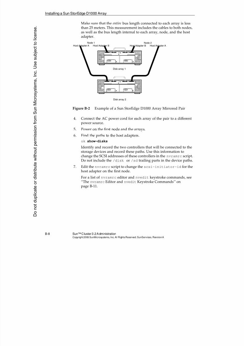
8/4/2019 Sun Cluster 3.2 Administration VC-ES-345
http://slidepdf.com/reader/full/sun-cluster-32-administration-vc-es-345 570/585
Installing a Sun StorEdge D1000 Array
B-8 Sun™Cluster 3 .2AdministrationCopyright2006 SunMicrosystems, Inc. AllRights Reserved.SunServices,RevisionA
Make sure that the entire bus length connected to each array is lessthan 25 meters. This measurement includes the cables to both nodes,as well as the bus length internal to each array, node, and the hostadapter.
Figure B-2 Example of a Sun StorEdge D1000 Array Mirrored Pair
4. Connect the AC power cord for each array of the pair to a differentpower source.
5. Power on the first node and the arrays.
6. Find the paths to the host adapters.
ok show-disks
Identify and record the two controllers that will be connected to thestorage devices and record these paths. Use this information tochange the SCSI addresses of these controllers in the nvramrc script.Do not include the /disk or /sd trailing parts in the device paths.
7. Edit the nvramrc script to change the scsi-initiator-id for thehost adapter on the first node.
For a list of nvramrc editor and nvedit keystroke commands, see‘‘The nvramrc Editor and nvedit Keystroke Commands’’ on
page B-11.
Node 1
Host Adapter A Host Adapter B
Node 2
Host Adapter B Host Adapter A
Disk array 1
Disk array 2
Donotduplicate
ordistributewithoutpermissionfrom SunMicrosystems,Inc.Usesubject
tolicense.
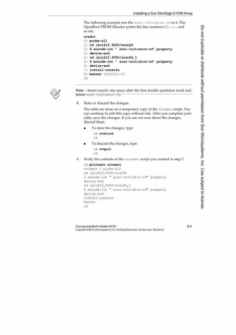
8/4/2019 Sun Cluster 3.2 Administration VC-ES-345
http://slidepdf.com/reader/full/sun-cluster-32-administration-vc-es-345 571/585
Installing a Sun StorEdge D1000 Array
Configuring Multi-Initiator SCSI B-9Copyright2006 SunMicrosystems, Inc. AllRightsReserved. SunServices,RevisionA
The following example sets the scsi-initiator-id to 6. TheOpenBoot PROM Monitor prints the line numbers (0:, 1:, andso on).
nvedit
0: probe-all
1: cd /pci@1f,4000/scsi@42: 6 encode-int " scsi-initiator-id" property
3: device-end
4: cd /pci@1f,4000/scsi@4,1
5: 6 encode-int " scsi-initiator-id" property
6: device-end
7: install-console
8: banner <Control-C>
ok
Note – Insert exactly one space after the first double quotation mark and before scsi-initiator-id.
8. Store or discard the changes.
The edits are done on a temporary copy of the nvramrc script. Youcan continue to edit this copy without risk. After you complete youredits, save the changes. If you are not sure about the changes,discard them.
q To store the changes, type:
ok nvstore
ok
q To discard the changes, type:
ok nvquit
ok
9. Verify the contents of the nvramrc script you created in step 7.
ok printenv nvramrc
nvramrc = probe-all
cd /pci@1f,4000/scsi@4
6 encode-int " scsi-initiator-id" property
device-endcd /pci@1f,4000/scsi@4,1
6 encode-int " scsi-initiator-id" property
device-end
install-console
banner
ok
8/4/2019 Sun Cluster 3.2 Administration VC-ES-345
http://slidepdf.com/reader/full/sun-cluster-32-administration-vc-es-345 572/585
Installing a Sun StorEdge D1000 Array
B-10 Sun™ Cluster 3.2 AdministrationCopyright2006 SunMicrosystems, Inc. AllRights Reserved.SunServices,RevisionA
10. Instruct the OpenBoot PROM Monitor to use the nvramrc script.
ok setenv use-nvramrc? true
use-nvramrc? = true
ok
11. Without allowing the node to boot, power on the second node. Ifnecessary, abort the system to continue with OpenBoot PROMMonitor tasks.
12. Verify that the scsi-initiator-id for each host adapter on thesecond node is set to 7.
ok cd /pci@1f,4000/scsi@4
ok .properties
scsi-initiator-id 00000007
differential
isp-fcode 1.21 95/05/18
device_type scsi
...
13. Continue with the Solaris OS, Sun Cluster software, and volumemanagement software installation tasks.
For software installation procedures, refer to Sun™ Cluster 3.1 InstallationGuide.
Donotduplicate
ordistributewithoutpermissionfrom SunMicrosystems,Inc.Usesubject
tolicense.
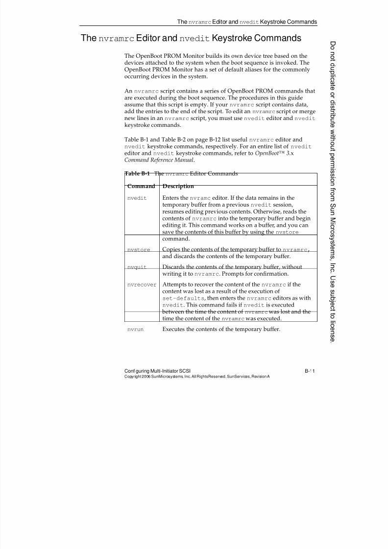
8/4/2019 Sun Cluster 3.2 Administration VC-ES-345
http://slidepdf.com/reader/full/sun-cluster-32-administration-vc-es-345 573/585
The nvramrcEditor and nveditKeystroke Commands
Configuring Multi-Initiator SCSI B-11Copyright2006 SunMicrosystems, Inc. AllRightsReserved. SunServices,RevisionA
The nvramrcEditor and nveditKeystroke Commands
The OpenBoot PROM Monitor builds its own device tree based on thedevices attached to the system when the boot sequence is invoked. TheOpenBoot PROM Monitor has a set of default aliases for the commonlyoccurring devices in the system.
An nvramrc script contains a series of OpenBoot PROM commands thatare executed during the boot sequence. The procedures in this guideassume that this script is empty. If your nvramrc script contains data,add the entries to the end of the script. To edit an nvramrc script or mergenew lines in an nvramrc script, you must use nvedit editor and nvedit
keystroke commands.
Table B-1 and Table B-2 on page B-12 list useful nvramrc editor and
nvedit keystroke commands, respectively. For an entire list of nvediteditor and nvedit keystroke commands, refer to OpenBoot™ 3.xCommand Reference Manual.
Table B-1 The nvramrc Editor Commands
Command Description
nvedit Enters the nvramc editor. If the data remains in thetemporary buffer from a previous nvedit session,resumes editing previous contents. Otherwise, reads thecontents of nvramrc into the temporary buffer and beginediting it. This command works on a buffer, and you cansave the contents of this buffer by using the nvstorecommand.
nvstore Copies the contents of the temporary buffer to nvramrc,and discards the contents of the temporary buffer.
nvquit Discards the contents of the temporary buffer, withoutwriting it to nvramrc. Prompts for confirmation.
nvrecover Attempts to recover the content of the nvramrc if thecontent was lost as a result of the execution of
set-defaults, then enters the nvramrc editors as withnvedit. This command fails if nvedit is executed between the time the content of nvramrcwas lost and thetime the content of the nvramrcwas executed.
nvrun Executes the contents of the temporary buffer.
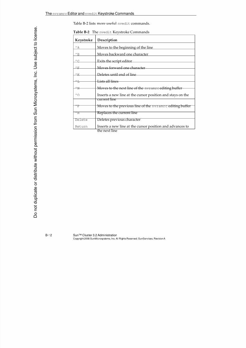
8/4/2019 Sun Cluster 3.2 Administration VC-ES-345
http://slidepdf.com/reader/full/sun-cluster-32-administration-vc-es-345 574/585
The nvramrcEditor andnveditKeystroke Commands
B-12 Sun™ Cluster 3.2 AdministrationCopyright2006 SunMicrosystems, Inc. AllRights Reserved.SunServices,RevisionA
Table B-2 lists more useful nvedit commands.
Table B-2 The nvedit Keystroke Commands
Keystroke Description
^A Moves to the beginning of the line
^B Moves backward one character
^C Exits the script editor
^F Moves forward one character
^K Deletes until end of line
^L Lists all lines
^N Moves to the next line of the nvramrc editing buffer
^O Inserts a new line at the cursor position and stays on thecurrent line
^P Moves to the previous line of the nvramrc editing buffer
^R Replaces the current line
Delete Deletes previous character
Return Inserts a new line at the cursor position and advances tothe next line
Donotduplicate
ordistributewithoutpermissionfrom SunMicrosystems,Inc.Usesubject
tolicense.
8/4/2019 Sun Cluster 3.2 Administration VC-ES-345
http://slidepdf.com/reader/full/sun-cluster-32-administration-vc-es-345 575/585
C-1Copyright2006 SunMicrosystems, Inc. AllRights Reserved.SunServices,RevisionA
Appendix C
Quorum Server
This appendix describes basic operation of the quorum server software.
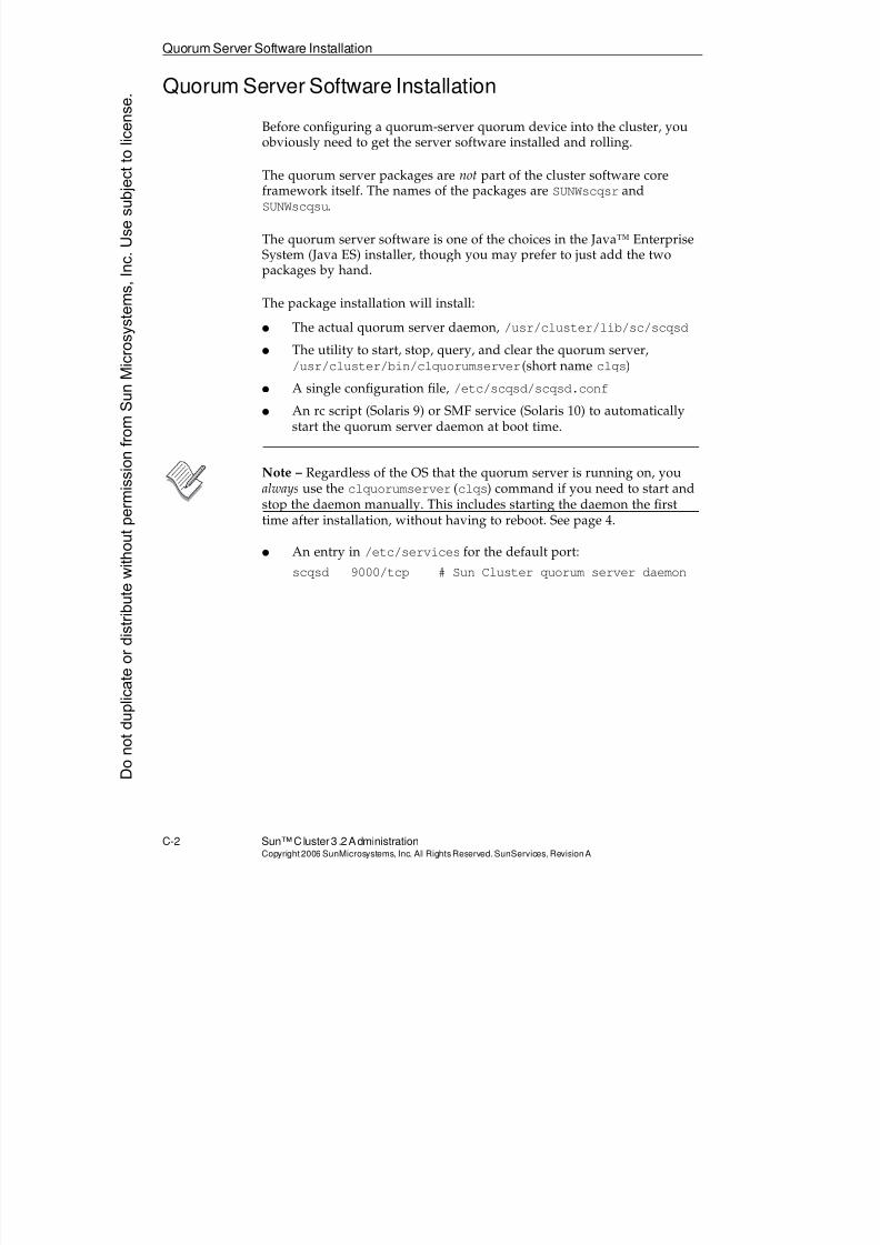
8/4/2019 Sun Cluster 3.2 Administration VC-ES-345
http://slidepdf.com/reader/full/sun-cluster-32-administration-vc-es-345 576/585
Quorum Server Software Installation
C-2 Sun™Cluster 3 .2AdministrationCopyright2006 SunMicrosystems, Inc. AllRights Reserved.SunServices,RevisionA
Quorum Server Software Installation
Before configuring a quorum-server quorum device into the cluster, youobviously need to get the server software installed and rolling.
The quorum server packages are not part of the cluster software coreframework itself. The names of the packages are SUNWscqsr andSUNWscqsu.
The quorum server software is one of the choices in the Java™ EnterpriseSystem (Java ES) installer, though you may prefer to just add the twopackages by hand.
The package installation will install:
q The actual quorum server daemon, /usr/cluster/lib/sc/scqsd
q The utility to start, stop, query, and clear the quorum server,/usr/cluster/bin/clquorumserver (short name clqs)
q A single configuration file, /etc/scqsd/scqsd.conf
q An rc script (Solaris 9) or SMF service (Solaris 10) to automaticallystart the quorum server daemon at boot time.
Note – Regardless of the OS that the quorum server is running on, youalways use the clquorumserver (clqs) command if you need to start and
stop the daemon manually. This includes starting the daemon the firsttime after installation, without having to reboot. See page 4.
q An entry in /etc/services for the default port:
scqsd 9000/tcp # Sun Cluster quorum server daemon
Donotduplicate
ordistributewithoutpermissionfrom SunMicrosystems,Inc.Usesubject
tolicense.
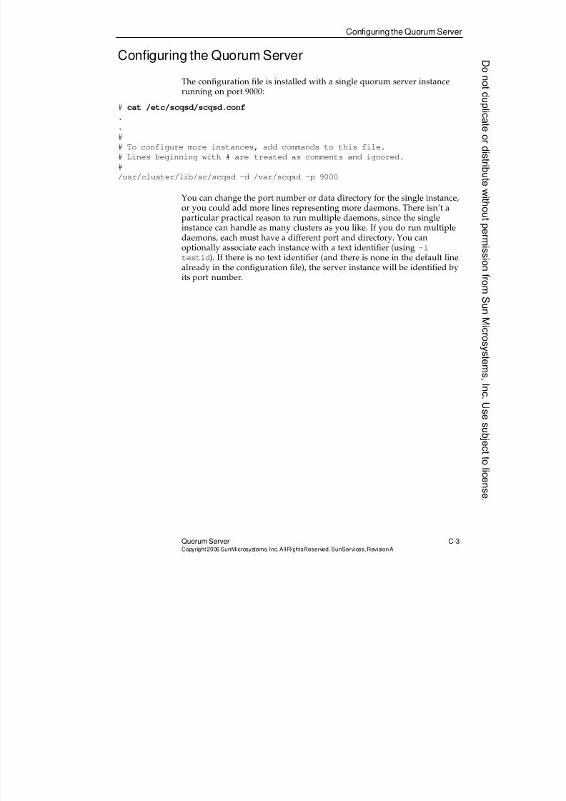
8/4/2019 Sun Cluster 3.2 Administration VC-ES-345
http://slidepdf.com/reader/full/sun-cluster-32-administration-vc-es-345 577/585
Configuring the Quorum Server
Quorum Server C-3Copyright2006 SunMicrosystems, Inc. AllRightsReserved. SunServices,RevisionA
Configuring the Quorum Server
The configuration file is installed with a single quorum server instancerunning on port 9000:
# cat /etc/scqsd/scqsd.conf.
.
#
# To configure more instances, add commands to this file.
# Lines beginning with # are treated as comments and ignored.
#
/usr/cluster/lib/sc/scqsd -d /var/scqsd -p 9000
You can change the port number or data directory for the single instance,or you could add more lines representing more daemons. There isn’t a
particular practical reason to run multiple daemons, since the singleinstance can handle as many clusters as you like. If you do run multipledaemons, each must have a different port and directory. You canoptionally associate each instance with a text identifier (using -i
textid). If there is no text identifier (and there is none in the default linealready in the configuration file), the server instance will be identified byits port number.
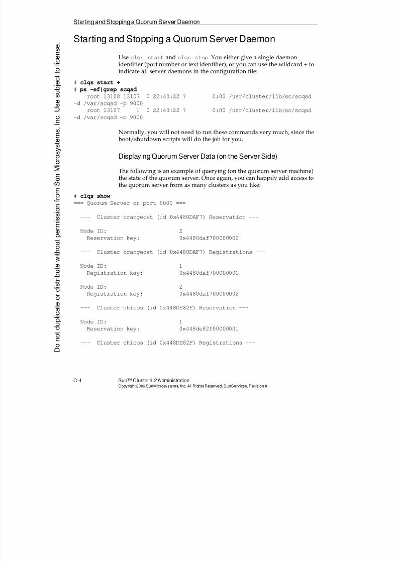
8/4/2019 Sun Cluster 3.2 Administration VC-ES-345
http://slidepdf.com/reader/full/sun-cluster-32-administration-vc-es-345 578/585
Starting andStopping a Quorum Server Daemon
C-4 Sun™Cluster 3 .2AdministrationCopyright2006 SunMicrosystems, Inc. AllRights Reserved.SunServices,RevisionA
Starting and Stopping a Quorum Server Daemon
Use clqs start and clqs stop. You either give a single daemonidentifier (port number or text identifier), or you can use the wildcard + toindicate all server daemons in the configuration file:
# clqs start +
# ps -ef|grep scqsd
root 13108 13107 0 22:40:22 ? 0:00 /usr/cluster/lib/sc/scqsd
-d /var/scqsd -p 9000
root 13107 1 0 22:40:22 ? 0:00 /usr/cluster/lib/sc/scqsd
-d /var/scqsd -p 9000
Normally, you will not need to run these commands very much, since the boot/shutdown scripts will do the job for you.
Displaying Quorum Server Data (on the Server Side)
The following is an example of querying (on the quorum server machine)the state of the quorum server. Once again, you can happily add access tothe quorum server from as many clusters as you like:
# clqs show
=== Quorum Server on port 9000 ===
--- Cluster orangecat (id 0x4480DAF7) Reservation ---
Node ID: 2
Reservation key: 0x4480daf700000002
--- Cluster orangecat (id 0x4480DAF7) Registrations ---
Node ID: 1
Registration key: 0x4480daf700000001
Node ID: 2
Registration key: 0x4480daf700000002
--- Cluster chicos (id 0x448DE82F) Reservation ---
Node ID: 1
Reservation key: 0x448de82f00000001
--- Cluster chicos (id 0x448DE82F) Registrations ---
Donotduplicate
ordistributewithoutpermissionfrom SunMicrosystems,Inc.Usesubject
tolicense.
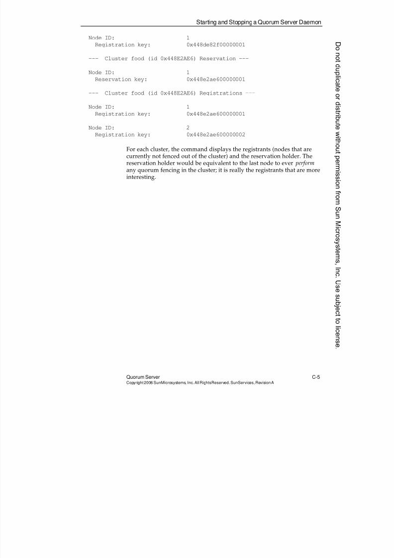
8/4/2019 Sun Cluster 3.2 Administration VC-ES-345
http://slidepdf.com/reader/full/sun-cluster-32-administration-vc-es-345 579/585
Starting and Stopping a Quorum Server Daemon
Quorum Server C-5Copyright2006 SunMicrosystems, Inc. AllRightsReserved. SunServices,RevisionA
Node ID: 1
Registration key: 0x448de82f00000001
--- Cluster food (id 0x448E2AE6) Reservation ---
Node ID: 1
Reservation key: 0x448e2ae600000001
--- Cluster food (id 0x448E2AE6) Registrations ---
Node ID: 1
Registration key: 0x448e2ae600000001
Node ID: 2
Registration key: 0x448e2ae600000002
For each cluster, the command displays the registrants (nodes that arecurrently not fenced out of the cluster) and the reservation holder. Thereservation holder would be equivalent to the last node to ever performany quorum fencing in the cluster; it is really the registrants that are moreinteresting.
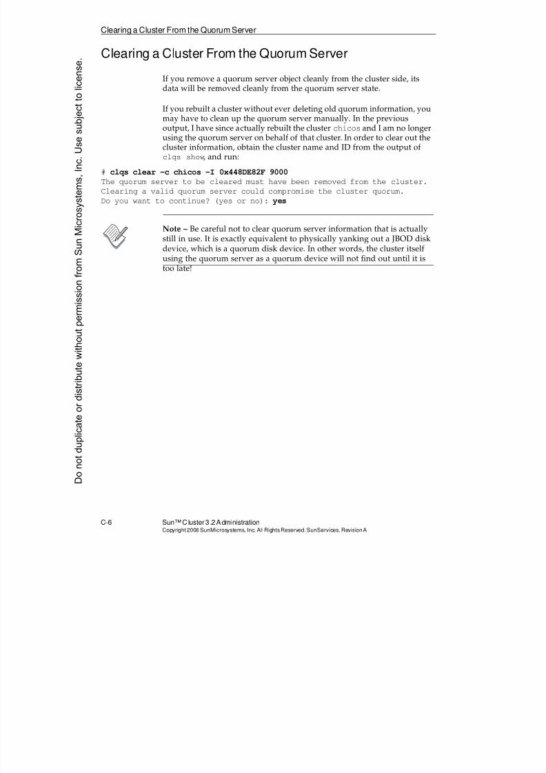
8/4/2019 Sun Cluster 3.2 Administration VC-ES-345
http://slidepdf.com/reader/full/sun-cluster-32-administration-vc-es-345 580/585
Clearing a Cluster From the Quorum Server
C-6 Sun™Cluster 3 .2AdministrationCopyright2006 SunMicrosystems, Inc. AllRights Reserved.SunServices,RevisionA
Clearing a Cluster From the Quorum Server
If you remove a quorum server object cleanly from the cluster side, itsdata will be removed cleanly from the quorum server state.
If you rebuilt a cluster without ever deleting old quorum information, youmay have to clean up the quorum server manually. In the previousoutput, I have since actually rebuilt the cluster chicos and I am no longerusing the quorum server on behalf of that cluster. In order to clear out thecluster information, obtain the cluster name and ID from the output ofclqs show, and run:
# clqs clear -c chicos -I 0x448DE82F 9000
The quorum server to be cleared must have been removed from the cluster.
Clearing a valid quorum server could compromise the cluster quorum.
Do you want to continue? (yes or no): yes
Note – Be careful not to clear quorum server information that is actuallystill in use. It is exactly equivalent to physically yanking out a JBOD diskdevice, which is a quorum disk device. In other words, the cluster itselfusing the quorum server as a quorum device will not find out until it istoo late!
Donotduplicate
ordistributewithoutpermissionfrom SunMicrosystems,Inc.Usesubject
tolicense.
8/4/2019 Sun Cluster 3.2 Administration VC-ES-345
http://slidepdf.com/reader/full/sun-cluster-32-administration-vc-es-345 581/585
D-1Copyright2006 SunMicrosystems, Inc. AllRights Reserved.SunServices,RevisionA
Appendix D
Role-BasedAccessControl
This appendix provides a brief review of role-based access control(RBAC).
8/4/2019 Sun Cluster 3.2 Administration VC-ES-345
http://slidepdf.com/reader/full/sun-cluster-32-administration-vc-es-345 582/585
Brief Review of RBAC Terminology
D-2 Sun™Cluster 3 .2AdministrationCopyright2006 SunMicrosystems, Inc. AllRights Reserved.SunServices,RevisionA
Brief Review of RBAC Terminology
Because RBAC can be confusing, the following sections provide a reviewof basic RBAC concepts to help you understand its integration into thecluster.
Role
A role is like a user, except for the following:
q You can not log in to it directly. You must log in as a user and thenuse the su command to switch to the role.
q Only certain users are allowed to switch to the role.
A role is meant to replace an old-style “privileged user,” where theintention is that multiple administrators assume this identity when theyneed to do privileged tasks. The advantage is that you must log in as aregular user and also know the password for the role and be allowed toassume the role to assume the identity.
Roles have entries in the passwd and shadow databases just like regularusers. Most often, roles are assigned one of the “pf-shells” so they can runprivileged commands, but this is not a requirement.
Authorization
Authorizations are meant to convey certain rights to users or roles, butauthorizations are interpreted only by RBAC-aware applications. In otherwords, having a particular authorization means nothing unless thesoftware you are running is specifically “instrumented” to check for yourauthorization and grant you a particular right to do a task.
Authorizations have names like solaris.cluster.modify andsolaris.cluster.read. The names form a natural hierarchy, so that
assigning solaris.cluster.* has the meaning that you expect.
Donotduplicate
ordistributewithoutpermissionfrom SunMicrosystems,Inc.Usesubject
tolicense.
8/4/2019 Sun Cluster 3.2 Administration VC-ES-345
http://slidepdf.com/reader/full/sun-cluster-32-administration-vc-es-345 583/585
Brief Review of RBAC Terminology
Role-Based Access Control D-3Copyright2006 SunMicrosystems, Inc. AllRightsReserved. SunServices,RevisionA
Assigning Authorizations
Authorizations can be assigned to users or roles, or they can be part of“rights profiles,” which are collections of authorizations and commandprivileges. The rights profiles could then be assigned to users or roles,
rather than the individual authorizations.
Command Privileges
Command privliges have been enhanced in the Solaris 10 OS:
Solaris 9 OS and Earlier
Command privileges allow users or roles to run certain commands with a
different real user ID (uid), effective user ID (euid), or both. This issimilar to turning the setuid bit on. But unlike the setuid bit, this RBACmechanism lets you restrict which users or roles are allowed to obtaincommand privileges.
Starting With Solaris 10 OS
Solaris 10 augments the Solaris 9 command privileges feature to support fine grained privileges over a specific command. For example, a user can begiven the privilege to run a specific command and have root-like ability to
read all files regardless of their permissions, but still be denied theprivilege to write all files.
Profiles
Profiles are collections of authorizations and command privileges.
Authorizations can be assigned directly to a user or role or throughinclusion in a profile assigned to the user or role.
Command privileges can be assigned only to a user or role through itsinclusion in a profile.
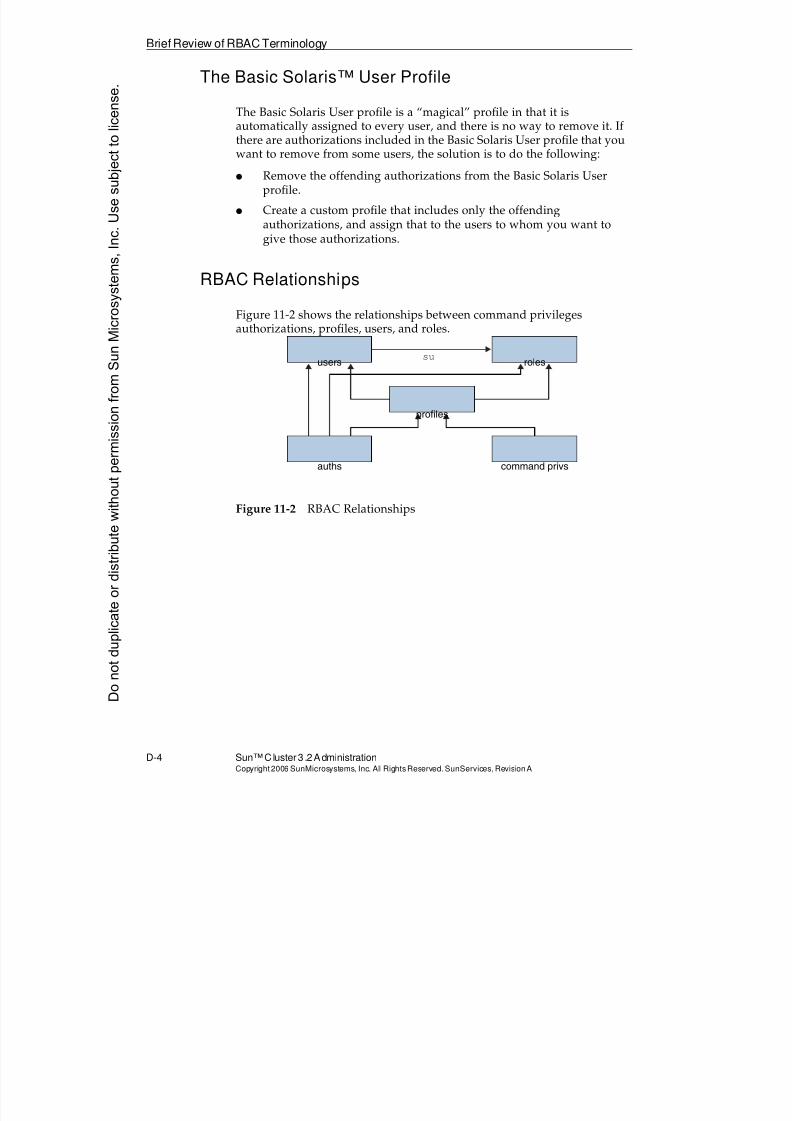
8/4/2019 Sun Cluster 3.2 Administration VC-ES-345
http://slidepdf.com/reader/full/sun-cluster-32-administration-vc-es-345 584/585
Brief Review of RBAC Terminology
D-4 Sun™Cluster 3 .2AdministrationCopyright2006 SunMicrosystems, Inc. AllRights Reserved.SunServices,RevisionA
The Basic Solaris™ User Profile
The Basic Solaris User profile is a “magical” profile in that it isautomatically assigned to every user, and there is no way to remove it. Ifthere are authorizations included in the Basic Solaris User profile that you
want to remove from some users, the solution is to do the following:
q Remove the offending authorizations from the Basic Solaris Userprofile.
q Create a custom profile that includes only the offendingauthorizations, and assign that to the users to whom you want togive those authorizations.
RBAC Relationships
Figure 11-2 shows the relationships between command privilegesauthorizations, profiles, users, and roles.
Figure 11-2 RBAC Relationships
users roles
command privsauths
profiles
su
Donotduplicate
ordistributewithoutpermissionfrom SunMicrosystems,Inc.Usesubject
tolicense.
8/4/2019 Sun Cluster 3.2 Administration VC-ES-345
http://slidepdf.com/reader/full/sun-cluster-32-administration-vc-es-345 585/585
Simplified RBAC Authorizations in theSun™ Cluster 3.2Environment
Simplified RBAC Authorizations in the Sun™ Cluster 3.2Environment
All the software is fully instrumented to understand RBAC