![Ufjf Disciplinas Maquete 20111 Aula01a Bibliografia v00[1]](https://static.fdocumentos.tips/doc/165x107/5571fde849795991699a3816/ufjf-disciplinas-maquete-20111-aula01a-bibliografia-v001.jpg)
Ricoh Mpw2400 Mpw3600 Ms v00
622
B286/B289 SERVICE MANUAL 003165MIU CÓPIA NÃO CONTROLADA CÓPIA NÃO CONTROLADA
Transcript of Ricoh Mpw2400 Mpw3600 Ms v00

B286/B289 SERVICE MANUAL
003165MIU
CÓPIA NÃO CONTROLADA
CÓPIA NÃO CONTROLADA

CÓPIA NÃO CONTROLADA
CÓPIA NÃO CONTROLADA

B286/B
289 SER
VICE M
AN
UA
L
CÓPIA NÃO CONTROLADA
CÓPIA NÃO CONTROLADA

CÓPIA NÃO CONTROLADA
CÓPIA NÃO CONTROLADA
B286/B289 SERVICE MANUAL
003165MIU
CÓPIA NÃO CONTROLADA
CÓPIA NÃO CONTROLADA

CÓPIA NÃO CONTROLADA
CÓPIA NÃO CONTROLADA
It is the reader's responsibility when discussing the information contained within this document to maintain a level of confidentiality that is in the best interest of Ricoh Americas Corporation and its member companies.
NO PART OF THIS DOCUMENT MAY BE REPRODUCED IN ANY FASHION AND DISTRIBUTED WITHOUT THE PRIOR PERMISSION OF RICOH AMERICAS CORPORATION.
All product names, domain names or product illustrations, including desktop images, used in this document are trademarks, registered trademarks or the property of their respective companies. They are used throughout this book in an informational or editorial fashion only and for the benefit of such companies. No such use, or the use of any trade name, or web site is intended to convey endorsement or other affiliation with Ricoh products.
© 2007 RICOH Americas Corporation. All rights reserved.
CÓPIA NÃO CONTROLADA
CÓPIA NÃO CONTROLADA

CÓPIA NÃO CONTROLADA
CÓPIA NÃO CONTROLADA

The Service Manual contains information regarding service techniques, procedures, processes and spare parts of office equipment distributed by Ricoh Americas Corporation. Users of this manual should be either service trained or certified by successfully completing a Ricoh Technical Training Program.
Untrained and uncertified users utilizing information contained in this service manual to repair or modify Ricoh equipment risk personal injury, damage to property or loss of warranty protection.
Ricoh Americas Corporation
WARNING
CÓPIA NÃO CONTROLADA
CÓPIA NÃO CONTROLADA

CÓPIA NÃO CONTROLADA
CÓPIA NÃO CONTROLADA

LEGEND
PRODUCT CODE COMPANY Gestetner LANIER RICOH SAVIN
B286 GWD2004 LW324 MPW2400 2404WD B289 GWD2006 LW336 MPW3600 2406WD
DOCUMENTATION HISTORY
REV. NO. DATE COMMENTS * 07/2007 Original Printing
CÓPIA NÃO CONTROLADA
CÓPIA NÃO CONTROLADA

CÓPIA NÃO CONTROLADA
CÓPIA NÃO CONTROLADA
SM i B286/B289
B286/B289 TABLE OF CONTENTS
INSTALLATION
1. INSTALLATION ........................................................................... 1-1 1.1 PREPARATION ......................................................................................... 1-1
1.1.1 ENVIRONMENT ............................................................................... 1-1 1.1.2 MINIMUM SPACE REQUIREMENTS............................................... 1-2 1.1.3 MACHINE LEVEL ............................................................................. 1-2 1.1.4 POWER SOURCE ............................................................................ 1-2 1.1.5 INSTALLATION OVERVIEW ............................................................ 1-3
Installation Flow.................................................................................... 1-3 SP and User Tool Settings Required for Installation ............................ 1-4
1.2 MAIN MACHINE INSTALLATION (B286) .................................................. 1-7 1.2.1 ACCESSORY CHECK...................................................................... 1-7 1.2.2 MACHINE INSTALLATION PROCEDURE ....................................... 1-8
Removing the Shipping Material........................................................... 1-8 Set the Operation Panel Position ......................................................... 1-9 Setting the Main Machine on the Roll Feeder (B851/B852) or Table (B854)............................................................................................................. 1-9 Leveling the Main Machine and Attaching Leg Covers....................... 1-14 Developer ........................................................................................... 1-16 Toner Cartridge Installation ................................................................ 1-17 Enter Developer Lot Numbers ............................................................ 1-19 Mix Developer and Initialize ID Sensor............................................... 1-19
1.2.3 MAIN MACHINE FINAL INSTALLATION........................................ 1-21 Select the Tray Paper Size and Type................................................. 1-21 Testing the Main Machine Circuit Breaker.......................................... 1-21 Main Machine Accessories................................................................. 1-22 Roll Feeder, Table Accessories.......................................................... 1-23 Copy Check........................................................................................ 1-25 Enable Onboard NIB, USB Functions ................................................ 1-25
1.2.4 MOVING THE MACHINE................................................................ 1-25
CÓPIA NÃO CONTROLADA
CÓPIA NÃO CONTROLADA
B286/B289 ii SM
1.3 ORIGINAL HANGER (D311).................................................................... 1-27 1.3.1 ACCESSORY CHECK.................................................................... 1-27 1.3.2 INSTALLATION .............................................................................. 1-27
1.4 ROLL FEEDER (B851/B852) ................................................................... 1-28 1.4.1 ACCESSORY CHECK.................................................................... 1-28 1.4.2 ROLL FEEDER INSTALLATION PROCEDURE............................. 1-29
Setting the Main Machine on the Roll Feeder .................................... 1-29 Opening the Roll Feeder and Removing Shipping Material................ 1-30 Leveling the Main Machine and Attaching Leg Covers....................... 1-35 Connecting the Main Machine and Roll Feeder.................................. 1-37 Attaching the Narrow Mylars to the Main Machine ............................. 1-40 Attaching the Wide Mylars to the Back of the Roll Feeder ................. 1-41 Securing the Power Cord ................................................................... 1-42 Installing the Paper Rolls.................................................................... 1-42 Attaching the Lower Output Tray, Exit Guide Plates .......................... 1-43 Entering the Cut Length Adjustment................................................... 1-44 Setting Paper Sizes/Types for the Tray 1 (1st Roll), Tray 2 (2nd Roll) . 1-44
1.5 PAPER CASSETTE (B853) ..................................................................... 1-45 1.5.1 ACCESSORY CHECK.................................................................... 1-45 1.5.2 PAPER CASSETTE INSTALLATION PROCEDURE...................... 1-45
1.6 TABLE (B854) .......................................................................................... 1-48 1.6.1 ACCESSORY CHECK.................................................................... 1-48 1.6.2 INSTALLATION PROCEDURE....................................................... 1-49
Setting the Main Machine on the Table .............................................. 1-49 Leveling the Main Machine and Attaching Leg Covers....................... 1-50 Attaching the Guide Plate................................................................... 1-50 Connecting the Main Machine and Table ........................................... 1-50 Attach the Narrow Mylars to the Main Machine .................................. 1-52 Attach the Wide Mylars to the Back of the Table................................ 1-53 Attaching the Stopper Brackets .......................................................... 1-54 Table Accessories .............................................................................. 1-54
1.7 INSTALLATION OF MFP OPTIONS........................................................ 1-56 1.7.1 OVERVIEW..................................................................................... 1-56 1.7.2 ENABLING THE ONBOARD FEATURES....................................... 1-57 1.7.3 USING SD CARDS ......................................................................... 1-58
Removing the SD Card Slot Cover..................................................... 1-58
CÓPIA NÃO CONTROLADA
CÓPIA NÃO CONTROLADA
SM iii B286/B289
SD Card Slot Assignments ................................................................. 1-58 Restrictions and Precautions on the Use of SD Cards ....................... 1-59 Application Move ................................................................................ 1-60 Undo Exec.......................................................................................... 1-60
1.7.4 PRINTER OPTION TYPE W3600 (D320) ....................................... 1-61 Accessories ........................................................................................ 1-61 Installation .......................................................................................... 1-62
1.7.5 SCANNER OPTION TYPE W3600 (D321) ..................................... 1-63 Accessories ........................................................................................ 1-63 Installation .......................................................................................... 1-63
1.7.6 FILE FORMAT CONVERTER TYPE C (B609-04) .......................... 1-64 Accessories ........................................................................................ 1-64 Installation .......................................................................................... 1-64
1.7.7 INTERFACE PCB (D329) ............................................................... 1-67 Accessories ........................................................................................ 1-67 Installation .......................................................................................... 1-67
1.7.8 IEEE802.11B INTERFACE UNIT TYPE H (G813-45)/TYPE I (G874-39) 1-69
Accessories ........................................................................................ 1-69 Installation .......................................................................................... 1-69
1.7.9 GIGABIT ETHERNET BOARD TYPE A (G874-01) ........................ 1-70 Accessories ........................................................................................ 1-70 Installation .......................................................................................... 1-70
1.7.10 DATA OVERWRITE SECURITY UNIT TYPE D (B735-18) ... 1-72 Accessories ........................................................................................ 1-72 Before You Begin�............................................................................ 1-72 Seal Check and Removal ................................................................... 1-72 Installation .......................................................................................... 1-72 Check Operation of the DOS Application ........................................... 1-74
1.7.11 USB HOST INTERFACE UNIT TYPE 7300 (G819-01) ......... 1-75 Accessories ........................................................................................ 1-75 Installation .......................................................................................... 1-75
CÓPIA NÃO CONTROLADA
CÓPIA NÃO CONTROLADA

B286/B289 iv SM
1.7.12 BROWSER UNIT TYPE C (B828-03) .................................... 1-76 Accessories ........................................................................................ 1-76 Installation .......................................................................................... 1-76
1.7.13 VM CARD TYPE E (D338-01, -02, -03) ................................. 1-77 Accessories ........................................................................................ 1-77 Installation .......................................................................................... 1-77
1.8 REAR STACKER (D312) ......................................................................... 1-79 1.8.1 ACCESSORIES .............................................................................. 1-79 1.8.2 INSTALLATION .............................................................................. 1-80
PREVENTIVE MAINTENANCE
2. PREVENTIVE MAINTENANCE ................................................... 2-1 2.1 PM TABLE ................................................................................................. 2-1
2.1.1 MAIN MACHINE (B286).................................................................... 2-1 2.1.2 ROLL FEEDER (B851/B852) ............................................................ 2-4 2.1.3 PAPER CASSETTE (B853) .............................................................. 2-5
2.2 CLEANING THE ENTRANCE SPURS....................................................... 2-6 2.3 LUBRICATION POINTS............................................................................. 2-7
2.3.1 DEVELOPMENT SECTION.............................................................. 2-7 2.3.2 FUSING GEARS............................................................................... 2-7
Rev. 10/2007
CÓPIA NÃO CONTROLADA
CÓPIA NÃO CONTROLADA
SM v B286/B289
REPLACEMENT AND ADJUSTMENT
3. REPLACEMENT AND ADJUSTMENT ........................................ 3-1 3.1 COMMON PROCEDURES ........................................................................ 3-1
3.1.1 BEFORE WORKING ON THE MAIN MACHINE............................... 3-1 3.1.2 SIDE COVERS ................................................................................. 3-2 3.1.3 REAR COVER .................................................................................. 3-3 3.1.4 PAPER EXIT UNIT ........................................................................... 3-3 3.1.5 UNLOCKING, OPENING THE ORIGINAL UNIT............................... 3-4 3.1.6 REMOVING THE ORIGINAL FEED UNIT ........................................ 3-5 3.1.7 RAISING AND LOCKING THE SCANNER UNIT.............................. 3-6 3.1.8 TONER HOPPER COVER................................................................ 3-7 3.1.9 IDLE REGISTRATION ROLLER PANEL .......................................... 3-7 3.1.10 MANUAL FEED TABLE, ORIGINAL FEED SENSOR COVER ... 3-8 3.1.11 DRAWER FRONT COVER ......................................................... 3-9
3.2 SCANNER ............................................................................................... 3-10 3.2.1 ORIGINAL WIDTH SENSORS, ORIGINAL SET SENSOR, SCANNER SWITCH................................................................................................... 3-10 3.2.2 ORIGINAL FEED UNIT ROLLERS ................................................. 3-11 3.2.3 EXPOSURE GLASS ....................................................................... 3-12 3.2.4 CIS.................................................................................................. 3-13 3.2.5 SMDB, VDB .................................................................................... 3-14 3.2.6 SIB, CGB POWER PACK ............................................................... 3-15
3.3 AROUND THE DRUM.............................................................................. 3-16 3.3.1 CHARGE CORONA WIRE, GRID WIRE, WIRE CLEANER ........... 3-16 3.3.2 QUENCHING LAMPS..................................................................... 3-17 3.3.3 LPH (LED PRINT HEAD) ................................................................ 3-18 3.3.4 TRANSFER CORONA, SEPARATION CORONA WIRES.............. 3-19
3.4 DEVELOPMENT...................................................................................... 3-21 3.4.1 DEVELOPMENT UNIT ................................................................... 3-21 3.4.2 DEVELOPER.................................................................................. 3-22 3.4.3 PAPER SET SENSOR, REGISTRATION SENSOR....................... 3-24 3.4.4 TONER SUPPLY CLUTCH............................................................. 3-25 3.4.5 DEVELOPMENT FILTER................................................................ 3-25
CÓPIA NÃO CONTROLADA
CÓPIA NÃO CONTROLADA
B286/B289 vi SM
3.4.6 USED TONER COLLECTION BOTTLE, TONER OVERFLOW SENSOR 3-26
3.5 DRUM ...................................................................................................... 3-27 3.5.1 DRUM UNIT.................................................................................... 3-27 3.5.2 CLEANING BLADE......................................................................... 3-29 3.5.3 ID SENSOR, PICK-OFF PAWLS, PICK-OFF PAWL SOLENOID... 3-30
3.6 PAPER FEED .......................................................................................... 3-31 3.6.1 REGISTRATION CLUTCH, REGISTRATION ROLLER.................. 3-31 3.6.2 ROLL 1 PAPER FEED CLUTCH, FEED ROLLER.......................... 3-33 3.6.3 ROLL 2 PAPER CLUTCH, FEED ROLLER .................................... 3-34 3.6.4 RF EXIT SENSOR .......................................................................... 3-35 3.6.5 ROLL FEED MOTOR...................................................................... 3-35 3.6.6 CUTTER MOTOR, HP SENSORS.................................................. 3-36 3.6.7 ROLL PAPER END SENSORS ...................................................... 3-37 3.6.8 CASSETTE FEED ROLLER ........................................................... 3-38 3.6.9 CASSETTE RELAY SENSOR, CASSETTE END SENSOR........... 3-38 3.6.10 CASSETTE FEED MOTOR, CASSETTE OPEN SENSOR....... 3-39 3.6.11 CASSETTE FEED CLUTCH ..................................................... 3-40
3.7 FUSING ................................................................................................... 3-41 3.7.1 PRESSURE SPRING ADJUSTMENT ............................................ 3-41 3.7.2 HOT ROLLER STRIPPERS............................................................ 3-42 3.7.3 FUSING EXIT SENSOR ................................................................. 3-42 3.7.4 PRESSURE ROLLER THERMISTORS.......................................... 3-43 3.7.5 PRESSURE ROLLER STRIPPERS................................................ 3-44 3.7.6 EXIT UNIT SWITCH ....................................................................... 3-44 3.7.7 FUSING UNIT ................................................................................. 3-45 3.7.8 FUSING CLEANING ROLLER........................................................ 3-46 3.7.9 FUSING LAMP................................................................................ 3-47 3.7.10 HOT ROLLER ........................................................................... 3-48 3.7.11 PRESSURE ROLLER ............................................................... 3-48 3.7.12 HOT ROLLER THERMISTOR, THERMOSTATS...................... 3-49
3.8 MOTORS ................................................................................................. 3-50 3.8.1 SCANNER MOTOR ........................................................................ 3-50 3.8.2 DRUM MOTOR............................................................................... 3-51 3.8.3 FUSING MOTOR, MAIN MOTOR................................................... 3-51 3.8.4 USED TONER BOTTLE MOTOR ................................................... 3-53
CÓPIA NÃO CONTROLADA
CÓPIA NÃO CONTROLADA

SM vii B286/B289
3.9 BOARDS.................................................................................................. 3-54 3.9.1 MCU/IPU/MB .................................................................................. 3-54 3.9.2 PSU/CIRCUIT BREAKER............................................................... 3-58 3.9.3 CONTROLLER BOARD.................................................................. 3-60 3.9.4 NVRAM........................................................................................... 3-63
NVRAM Upload .................................................................................. 3-63 NVRAM Download ............................................................................. 3-63
3.9.5 T&S POWER PACK........................................................................ 3-64 3.9.6 RFDB (ROLL FEEDER DRIVE BOARD) ........................................ 3-65 3.9.7 SFDB (SHEET FEED DRIVE BOARD)........................................... 3-65
3.10 OTHERS ............................................................................................ 3-67 3.10.1 HDD .......................................................................................... 3-67 3.10.2 COOLING FAN, OZONE FILTER.............................................. 3-68
3.11 SP ADJUSTMENTS ........................................................................... 3-70 3.11.1 IMAGE ADJUSTMENT WITH SP CODES ................................ 3-70
Step 1: Magnification for Paper Type: Plain ....................................... 3-70 Step 2: Scanning Magnification .......................................................... 3-71 Step 3: Magnification for Paper Type: Translucent............................. 3-71 Step 4: Magnification for Paper Type: Film ........................................ 3-72 Step 5: Scanner Mask Setting ............................................................ 3-72 Step 6: Erase Margins........................................................................ 3-72 Step 7: Printer: Leading Edge, Side-to-Side Registration................... 3-73 Step 8: Scanner Mask Setting ............................................................ 3-74 Step 9: Erase Margins........................................................................ 3-74 Step 10: Scanner Registration............................................................ 3-75 Step 11: Printer: Cut Length............................................................... 3-75 Step 12: Synchro Cut (Trailing Edge Registration)............................. 3-76
3.11.2 CIS ADJUSTMENT WITH SP CODES...................................... 3-77 To Print the CIS Adjustment Pattern .................................................. 3-77 To Adjust the Image at the CIS Joints ................................................ 3-78
3.11.3 LPH ADJUSTMENT WITH SP CODES..................................... 3-80 Doing SP Adjustment Settings for a Replacement LPH ..................... 3-80 To Print Pattern IPU Test Pattern 10.................................................. 3-81 Main Scan Adjustment: White, Black Vertical Lines ........................... 3-82 Main Scan Adjustment: LED Light Level at LPH Joints ...................... 3-83 Adjusting LPH Alignment.................................................................... 3-83
CÓPIA NÃO CONTROLADA
CÓPIA NÃO CONTROLADA

B286/B289 viii SM
3.11.4 LPH DENSITY ADJUSTMENT WITH SP CODES .................... 3-85 To Print the IPU Test Pattern 2 .......................................................... 3-85 To Correct Pattern Density ................................................................. 3-86
TROUBLESHOOTING
4. TROUBLESHOOTING ................................................................. 4-1 4.1 SERVICE CALL CONDITIONS.................................................................. 4-1 4.2 SC CODE DESCRIPTIONS....................................................................... 4-3
4.2.1 SC1XXX............................................................................................ 4-3 4.2.2 SC2XXX............................................................................................ 4-3 4.2.3 SC3XXX............................................................................................ 4-4 4.2.4 SC4XXX............................................................................................ 4-5 4.2.5 SC5XXX............................................................................................ 4-6 4.2.6 SC6XXX.......................................................................................... 4-11 4.2.7 SC7XXX.......................................................................................... 4-14 4.2.8 SC8XXX.......................................................................................... 4-16 4.2.9 SC9XXX.......................................................................................... 4-23
4.3 JAM CODE TABLES................................................................................ 4-28 4.3.1 OVERVIEW..................................................................................... 4-28 4.3.2 SCANNER JAMS............................................................................ 4-29
Scanner Standby Jams ...................................................................... 4-29 Scanner Late Jams ............................................................................ 4-31 Scanner Lag Jams ............................................................................. 4-31
4.3.3 PLOTTER (PRINTER) JAMS.......................................................... 4-31 Plotter Standby Jams ......................................................................... 4-31 Plotter Late Jams ............................................................................... 4-32 Plotter Lag Jams ................................................................................ 4-32
4.3.4 FOLDER UNIT JAMS ..................................................................... 4-33 Folder Unit Standby Jams .................................................................. 4-33 Folder Unit Late Jams ........................................................................ 4-34 Folder Unit Lag Jams ......................................................................... 4-35
4.4 COVER OPEN ......................................................................................... 4-36 4.5 FUSES ..................................................................................................... 4-37 4.6 IMAGE PROBLEM TROUBLESHOOTING .............................................. 4-38
CÓPIA NÃO CONTROLADA
CÓPIA NÃO CONTROLADA

SM ix B286/B289
4.6.1 FLOW CHART ................................................................................ 4-38 4.6.2 SCANNING..................................................................................... 4-39 4.6.3 PRINTING....................................................................................... 4-41 4.6.4 DENSITY CHANGES AT CIS JOINTS ........................................... 4-43 4.6.5 OTHER PROBLEMS ...................................................................... 4-44
4.7 BOARD LEDS.......................................................................................... 4-45 4.7.1 PSU, MCU, IPU .............................................................................. 4-45
PSU LEDs .......................................................................................... 4-45 MCU LEDs ......................................................................................... 4-46 IPU LEDs............................................................................................ 4-47
4.7.2 SIB, VDB......................................................................................... 4-48 VDB LEDs .......................................................................................... 4-48 SIB LEDs............................................................................................ 4-49 GW Controller Board .......................................................................... 4-49
SERVICE TABLES
5. SERVICE TABLES....................................................................... 5-1 5.1 USING THE SP MODE.............................................................................. 5-1
5.1.1 DIRECT ENTRY ............................................................................... 5-1 Normal Direct Entry .............................................................................. 5-1 Rapid Direct Entry ................................................................................ 5-2
5.2 FIRMWARE UPDATE ................................................................................ 5-3 5.2.1 OVERVIEW....................................................................................... 5-3 5.2.2 UPDATING FIRMWARE................................................................... 5-3
5.3 USER TOOLS............................................................................................ 5-6 5.3.1 USER TOOL SUMMARY.................................................................. 5-6
System Settings ................................................................................... 5-6 Copier/Document Server Features....................................................... 5-9 Espanol .............................................................................................. 5-12 Inquiry ................................................................................................ 5-12 Counter .............................................................................................. 5-12
5.4 INPUT CHECK......................................................................................... 5-13 5.5 OUTPUT CHECK..................................................................................... 5-19 5.6 SP TABLE KEY........................................................................................ 5-21
CÓPIA NÃO CONTROLADA
CÓPIA NÃO CONTROLADA

B286/B289 x SM
5.7 SP1-XXX FEED ....................................................................................... 5-22 5.7.1 PAPER THICKNESS DEFAULT SELECTION................................ 5-36
5.8 SP2-XXX DRUM ...................................................................................... 5-56 5.8.1 TEST PATTERN PRINTING........................................................... 5-72
5.9 SP3-XXX PROCESS CONTROL............................................................. 5-73 5.10 SP4-XXX SCANNER .............................................................................5-74 5.11 SP5-XXX MODE ....................................................................................5-97 5.12 SP6-XXX PERIPHERALS......................................................................5-160 5.13 SP7-XXX DATA LOG.............................................................................5-185 5.14 SP8-XXX DATA LOG 2..........................................................................5-196
DETAILS
6. DETAILS ...................................................................................... 6-1 6.1 OVERVIEW................................................................................................ 6-1
6.1.1 MACHINE GENERAL LAYOUT ........................................................ 6-1 6.1.2 MECHANICAL COMPONENT LAYOUT........................................... 6-3 6.1.3 DRIVE LAYOUT................................................................................ 6-5 6.1.4 ORIGINAL/COPY PAPER PATHS.................................................... 6-6
6.2 SCANNER ................................................................................................. 6-8 6.2.1 OVERVIEW....................................................................................... 6-8 6.2.2 SCANNER LAYOUT ......................................................................... 6-9 6.2.3 ORIGINAL WIDTH DETECTION .................................................... 6-10 6.2.4 ORIGINAL DRIVE MECHANISM .................................................... 6-11 6.2.5 ORIGINAL FEED SPEED ............................................................... 6-11 6.2.6 SCANNING MECHANISM .............................................................. 6-12
CIS Structure...................................................................................... 6-12 Printed Image..................................................................................... 6-13
6.2.7 AUTO IMAGE DENSITY CORRECTION........................................ 6-13 6.3 IMAGE PROCESSING............................................................................. 6-15
6.3.1 GENERAL IMAGE PROCESSING FLOWCHART.......................... 6-15 6.3.2 ORIGINAL MODES......................................................................... 6-16
Overview ............................................................................................ 6-16 Drawing Mode .................................................................................... 6-17 Text Mode .......................................................................................... 6-18
CÓPIA NÃO CONTROLADA
CÓPIA NÃO CONTROLADA
SM xi B286/B289
Text/Photo Mode ................................................................................ 6-19 Photo Mode........................................................................................ 6-19 Background Lines Mode..................................................................... 6-20 Patched Original Mode....................................................................... 6-21 Generation Mode................................................................................ 6-22
6.4 AROUND THE DRUM.............................................................................. 6-23 6.4.1 OVERVIEW..................................................................................... 6-23 6.4.2 DRUM DRIVE ................................................................................. 6-24 6.4.3 CHARGE CORONA UNIT............................................................... 6-25 6.4.4 CORONA WIRE CLEANING........................................................... 6-26 6.4.5 DRUM CLEANING.......................................................................... 6-27 6.4.6 COLLECTING USED TONER......................................................... 6-28 6.4.7 QUENCHING.................................................................................. 6-29 6.4.8 DRUM ANTI-CONDENSATION HEATERS .................................... 6-30
6.5 IMAGE WRITING..................................................................................... 6-31 6.6 DEVELOPMENT...................................................................................... 6-32
6.6.1 OVERVIEW..................................................................................... 6-32 6.6.2 DEVELOPMENT DRIVE MECHANISM .......................................... 6-33 6.6.3 TONER SUPPLY MECHANISM ..................................................... 6-34 6.6.4 DEVELOPER CROSS-MIXING ...................................................... 6-35 6.6.5 DEVELOPMENT BIAS.................................................................... 6-36 6.6.6 ID SENSOR .................................................................................... 6-37 6.6.7 WARMUP CONTROL (VSG CORRECTION) ................................. 6-38 6.6.8 TONER DENSITY CONTROL ........................................................ 6-39
Overview ............................................................................................ 6-39 Supply Modes..................................................................................... 6-39 Detect Supply Mode ........................................................................... 6-40 Fixed Supply Mode............................................................................. 6-41 Toner Supply Clutch Operation .......................................................... 6-41
6.6.9 TONER END/NEAR-END DETECTION.......................................... 6-43 Toner Near End.................................................................................. 6-43 Toner End........................................................................................... 6-43 Toner End Recovery .......................................................................... 6-43
6.7 PAPER FEED AND REGISTRATION...................................................... 6-45 6.7.1 OVERVIEW..................................................................................... 6-45
Layout Diagrams ................................................................................ 6-45
CÓPIA NÃO CONTROLADA
CÓPIA NÃO CONTROLADA

B286/B289 xii SM
Feed Station Overview ....................................................................... 6-47 Manual Feed Table ............................................................................ 6-48 Roll Feeder......................................................................................... 6-48 Paper Cassette................................................................................... 6-48 Paper Width and Type Settings.......................................................... 6-48
6.7.2 MANUAL FEED MECHANISM........................................................ 6-49 6.7.3 ROLL FEED MECHANISM ............................................................. 6-50
Drive................................................................................................... 6-50 Roll Pre-feeding.................................................................................. 6-51 Roll Paper Feed ................................................................................. 6-53
6.7.4 ROLL FEEDER PAPER HOLDERS................................................ 6-54 6.7.5 ROLL PAPER CUTTING MECHANISM.......................................... 6-55 6.7.6 ROLL END DETECTION ................................................................ 6-56 6.7.7 PAPER CASSETTE MECHANISM ................................................. 6-58 6.7.8 PAPER CASSETTE FEED ............................................................. 6-59
Cassette Paper Path .......................................................................... 6-59 Paper Cassette Pre-Feeding .............................................................. 6-60
6.7.9 PAPER CASSETTE PAPER END DETECTION............................. 6-61 6.7.10 CONDENSATION PREVENTION ............................................. 6-62 6.7.11 PAPER REGISTRATION .......................................................... 6-63
6.8 IMAGE TRANSFER AND SEPARATION................................................. 6-64 6.8.1 OVERVIEW..................................................................................... 6-64
Transfer Corona Unit .......................................................................... 6-64 Separation Corona Unit ...................................................................... 6-65
6.8.2 PICK-OFF PAWL OPERATION ...................................................... 6-65 6.9 FUSING UNIT .......................................................................................... 6-66
6.9.1 OVERVIEW..................................................................................... 6-66 6.9.2 PAPER FEED THROUGH THE FUSING UNIT .............................. 6-67 6.9.3 FUSING PRESSURE CONTROL MECHANISM ............................ 6-68 6.9.4 HOT ROLLER THERMISTORS AND THERMOSTATS ................. 6-69 6.9.5 TEMPERATURE CONTROL .......................................................... 6-69
Paper Thickness Setting .................................................................... 6-69 Zero-Cross Control Test ..................................................................... 6-71 Switching on the Fusing Lamp Power ................................................ 6-71 Fusing Temperature Control: Warm-up Sequence............................. 6-72 Fusing Temperature Control: Temperature Feedback During Copying6-74
CÓPIA NÃO CONTROLADA
CÓPIA NÃO CONTROLADA
SM xiii B286/B289
Pressure Roller Temperature Feedback ............................................ 6-76 Fusing Temperature Control: Inching ................................................. 6-79 Fusing Temperature Control: CPM Down .......................................... 6-79
6.9.6 HOT ROLLER CLEANING.............................................................. 6-80 6.9.7 FUSING UNIT DRIVE MECHANISM .............................................. 6-81 6.9.8 WRINKLE PREVENTION ............................................................... 6-82
Motor Speed Control .......................................................................... 6-82 Inching Control ................................................................................... 6-82
6.10 PAPER EXIT ...................................................................................... 6-83 6.10.1 OVERVIEW............................................................................... 6-83
Upper Exit........................................................................................... 6-83 Rear Exit............................................................................................. 6-84 Jam Detection .................................................................................... 6-84
6.10.2 SWITCHING THE PAPER EXIT................................................ 6-84 Upper Exit........................................................................................... 6-84 Rear Exit............................................................................................. 6-85
6.10.3 PAPER EXIT DRIVE ................................................................. 6-86 6.11 ELECTRICAL COMPONENTS........................................................... 6-87
6.11.1 OVERVIEW............................................................................... 6-87 Overall System................................................................................... 6-87 IPU Board Details............................................................................... 6-89
6.11.2 DESCRIPTION OF ELECTRICAL COMPONENTS .................. 6-90 6.11.3 MCU, IPU ................................................................................ 6-100
MCU (Main Control Unit) .................................................................. 6-100 IPU (Image Processing Unit) ............................................................ 6-101
6.11.4 PSU......................................................................................... 6-101 6.11.5 SMDB, VDB, SIB..................................................................... 6-102
SMDB (Scanner Motor Drive Board) ................................................ 6-102 VDB (Video Drive Board) ................................................................. 6-102 SIB (Scanner Interface Board) ......................................................... 6-102 CIS I/F (1 to 5).................................................................................. 6-102
6.11.6 RFDB, SFDB........................................................................... 6-103 RFDB (Roll Feed Drive Board) ......................................................... 6-103 SFDB (Sheet Feed Drive Board) ...................................................... 6-103
6.11.7 GW CONTROLLER BOARD................................................... 6-104
CÓPIA NÃO CONTROLADA
CÓPIA NÃO CONTROLADA
B286/B289 xiv SM
SPECIFICATIONS
7. SPECIFICATIONS........................................................................ 7-1 7.1 MAIN MACHINE (B286/B289) ................................................................... 7-1 7.2 OPTIONS................................................................................................... 7-6
7.2.1 ROLL FEEDER B851/B852 .............................................................. 7-6 7.2.2 FOLDER (D889) ............................................................................... 7-7 7.2.3 MANUAL FEEDER D333.................................................................. 7-8 7.2.4 PAPER CASSETTE B853................................................................. 7-9
7.3 MAIN MACHINE CONFIGURATION........................................................ 7-10
CÓPIA NÃO CONTROLADA
CÓPIA NÃO CONTROLADA

CÓPIA NÃO CONTROLADA
CÓPIA NÃO CONTROLADA
INSTALLATION
PREVENTIVE MAINTENANCE
REPLACEMENT AND ADJUSTMENT
TROUBLESHOOTING
SERVICE TABLES
DETAILED DESCRIPTIONS
SPECIFICATIONS
TAB
PO
SITI
ON
2
TAB
PO
SITI
ON
1
TAB
PO
SITI
ON
3
TAB
PO
SITI
ON
4
TAB
PO
SITI
ON
6
TAB
PO
SITI
ON
5
TAB
PO
SITI
ON
8
TAB
PO
SITI
ON
7
CÓPIA NÃO CONTROLADA
CÓPIA NÃO CONTROLADA

CÓPIA NÃO CONTROLADA
CÓPIA NÃO CONTROLADA
Read This First Safety, Conventions, Trademarks Safety PREVENTION OF PHYSICAL INJURY 1. Before disassembling or assembling parts of the machine and peripherals, make sure
that they are unplugged.
2. The plug should be near the machine and easily accessible.
3. Note that some components of the machine and the paper tray unit are supplied with
electrical voltage even if the main power switch is turned off.
4. If any adjustment or operation check has to be made with exterior covers off or open
while the main switch is turned on, keep hands away from electrified or mechanically
driven components.
5. If the [Start] key is pressed before the machine completes the warm-up period (the
[Start] key starts blinking red and green ), keep hands away from the mechanical and
the electrical components as the machine starts making copies as soon as the
warm-up period is completed.
6. The inside and the metal parts of the fusing unit become extremely hot while the
machine is operating. Be careful to avoid touching those components with your bare
hands.
HEALTH SAFETY CONDITIONS 1. Never operate the machine without the ozone filters installed.
2. Always replace the ozone filters with the specified types at the proper intervals.
3. Toner and developer are non-toxic, but if you get either of them in your eyes by
accident, it may cause temporary eye discomfort. Try to remove with eye drops or flush
with water as first aid. If unsuccessful, get medical attention.
OBSERVANCE OF ELECTRICAL SAFETY STANDARDS 1. The machine and its peripherals must be installed and maintained by a customer
service representative who has completed the training course on those models.
SAFETY AND ECOLOGICAL NOTES FOR DISPOSAL 1. Do not incinerate toner bottles or used toner. Toner dust may ignite suddenly when
exposed to an open flame.
2. Dispose of used toner, developer, and organic photoconductors in accordance with
local regulations. (These are non-toxic supplies.)
CÓPIA NÃO CONTROLADA
CÓPIA NÃO CONTROLADA
3. Dispose of replaced parts in accordance with local regulations.
4. When keeping used lithium batteries in order to dispose of them later, do not put more
than 100 batteries per sealed box. Storing larger numbers or not sealing them apart
may lead to chemical reactions and heat build-up.
! The danger of explosion exists if a battery of this type is incorrectly replaced.
Replace only with the same or an equivalent type recommended by the
manufacturer. Discard used batteries in accordance with the manufacturer�s
instructions.
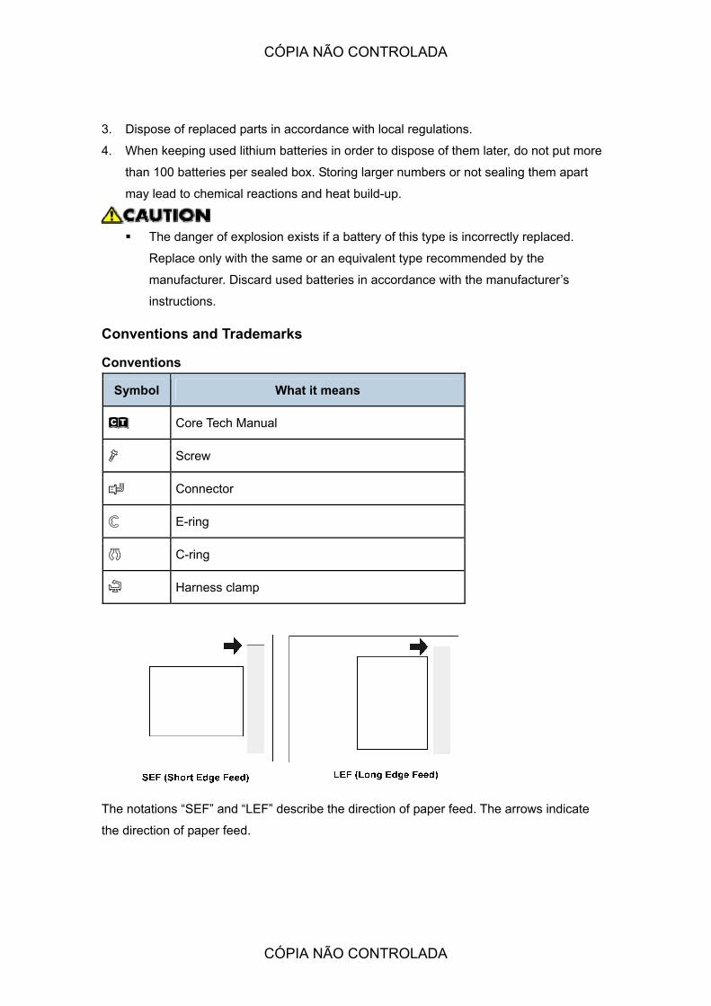
Conventions and Trademarks
Conventions
Symbol What it means
! Core Tech Manual
" Screw
# Connector
$ E-ring
% C-ring
& Harness clamp
The notations �SEF� and �LEF� describe the direction of paper feed. The arrows indicate
the direction of paper feed.
CÓPIA NÃO CONTROLADA
CÓPIA NÃO CONTROLADA
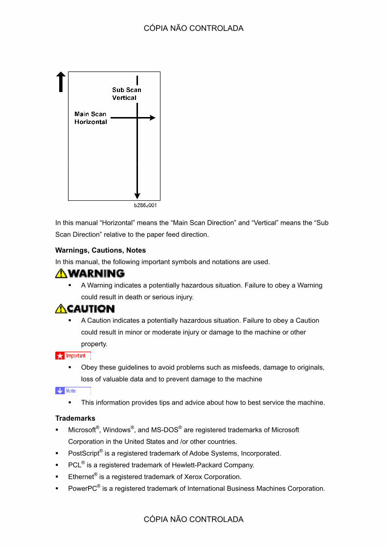
In this manual �Horizontal� means the �Main Scan Direction� and �Vertical� means the �Sub
Scan Direction� relative to the paper feed direction.
Warnings, Cautions, Notes In this manual, the following important symbols and notations are used.
! A Warning indicates a potentially hazardous situation. Failure to obey a Warning
could result in death or serious injury.
! A Caution indicates a potentially hazardous situation. Failure to obey a Caution
could result in minor or moderate injury or damage to the machine or other
property.
! Obey these guidelines to avoid problems such as misfeeds, damage to originals,
loss of valuable data and to prevent damage to the machine
! This information provides tips and advice about how to best service the machine.
Trademarks ! Microsoft®, Windows®, and MS-DOS® are registered trademarks of Microsoft
Corporation in the United States and /or other countries.
! PostScript® is a registered trademark of Adobe Systems, Incorporated.
! PCL® is a registered trademark of Hewlett-Packard Company.
! Ethernet® is a registered trademark of Xerox Corporation.
! PowerPC® is a registered trademark of International Business Machines Corporation.
CÓPIA NÃO CONTROLADA
CÓPIA NÃO CONTROLADA

! Other product names used herein are for identification purposes only and may be
trademarks of their respective companies. We disclaim any and all rights involved with
those marks.
CÓPIA NÃO CONTROLADA
CÓPIA NÃO CONTROLADA

CÓPIA NÃO CONTROLADA
CÓPIA NÃO CONTROLADA

INSTALLATION
CÓPIA NÃO CONTROLADA
CÓPIA NÃO CONTROLADA

CÓPIA NÃO CONTROLADA
CÓPIA NÃO CONTROLADA

Preparation
SM 1-1 B286/B289
Inst
alla
tion
1. INSTALLATION
1.1 PREPARATION
1.1.1 ENVIRONMENT
1. Temperature Range: 10 °C to 30 °C (50 °F to 86 °F)
2. Humidity Range: 15% to 90% RH
3. Ambient Illumination: Less than 1,500 Lux (do not expose the machine directly to light
from the sun).
4. Ventilation: More than 30 m3/hr/person in the work area
5. Ambient Dust: Less than 0.10 mg/m3
6. If the installation area has air-conditioners or heaters, put the machine in a location
where:
! There are no sudden temperature changes from low to high, or high to low.
! The machine will not be directly exposed to cool air from an air conditioner in the
summer.
! The machine will not be directly exposed to reflected heat from a space heater in
the winter.
7. Do not install the machine in an area filled with gases that can cause corrosion.
8. Do not install the machine in areas higher than 2,000 m (6,600 ft) above sea level.
CÓPIA NÃO CONTROLADA
CÓPIA NÃO CONTROLADA

Preparation
B286/B289 1-2 SM
9. Put the machine on a strong and level surface.
! The floor must be able to support a load of more than 2.94 kPa (300 kgf/m2.
10. Do not install the machine in an area where there are frequent strong vibrations.
1.1.2 MINIMUM SPACE REQUIREMENTS
1. Front: 1000 mm (40�)
2. Back: 600 mm (23�)
3. Right: 600 mm (23�)
4. Left: 600 mm (23�)
1.1.3 MACHINE LEVEL
1. Front to back: Not more than 5 mm from level
2. Right to left: Not more than 0.15/1000 mm from level.
1.1.4 POWER SOURCE
! This machine is provided with a circuit breaker that cuts the power supply to the
main machine in case of a current overload or short circuit. The machine must be
installed in a building where circuit breakers (and equivalent devices) can operate
properly.
1. Input Voltage Level:
! 120V, 60 Hz, 15 A or more
CÓPIA NÃO CONTROLADA
CÓPIA NÃO CONTROLADA

Preparation
SM 1-3 B286/B289
Inst
alla
tion
! 220-240V, 50/60 Hz, 10A or more
2. Permissible Voltage Fluctuation: ±10%
3. Do not set objects on the power cord.
! Make sure the plug is firmly inserted in the outlet.
! Do not connect the machine to a power source that is shared with other
equipment.
1.1.5 INSTALLATION OVERVIEW
Installation Flow This copier has these options.
! Roll feeder. You can install a roll feeder with one roll or two rolls. You can also install a
universal Paper Cassette in the roll feeder. You cannot install the paper cassette
without the roll feeder.
! Table. Used as an alternative to the roll feeder, it contains only the lower stacker.
Here is a summary of the sequence recommended for installation of all these options
together.
Installation Flow Diagram
Copier Pre-Installation
Remove the copier from its box. Remove all packing material and tape. Put the copier on
the roll feeder or the table.
'
Roll Feeder (or Table) Installation
'
Install Paper Cassette
'
SP and User Tool Settings for Installation
Do all the SP and User Tool settings for the copier and the installed options.
'
Copier Final Installation
Complete the installation of the copier after you put it on the roll feeder or table, and after
CÓPIA NÃO CONTROLADA
CÓPIA NÃO CONTROLADA
Preparation
B286/B289 1-4 SM
you install all options. Do some sample copies to check the operation of the copier and
installed options.
'
Printer/Scanner, Other MFP Options
Install the printer/scanner options and do a function check. For installation instructions,
refer to the installation manual for the Printer/Scanner controller.
'
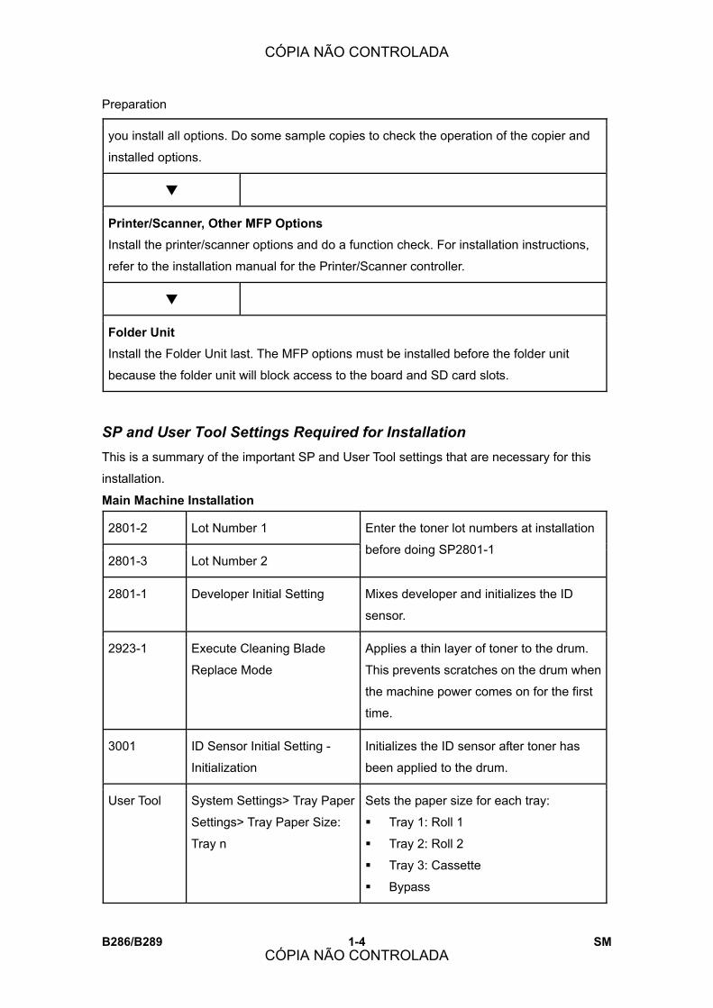
Folder Unit Install the Folder Unit last. The MFP options must be installed before the folder unit
because the folder unit will block access to the board and SD card slots.
SP and User Tool Settings Required for Installation This is a summary of the important SP and User Tool settings that are necessary for this
installation.
Main Machine Installation
2801-2 Lot Number 1
2801-3 Lot Number 2
Enter the toner lot numbers at installation
before doing SP2801-1
2801-1 Developer Initial Setting Mixes developer and initializes the ID
sensor.
2923-1 Execute Cleaning Blade
Replace Mode
Applies a thin layer of toner to the drum.
This prevents scratches on the drum when
the machine power comes on for the first
time.
3001 ID Sensor Initial Setting -
Initialization
Initializes the ID sensor after toner has
been applied to the drum.
User Tool System Settings> Tray Paper
Settings> Tray Paper Size:
Tray n
Sets the paper size for each tray:
! Tray 1: Roll 1
! Tray 2: Roll 2
! Tray 3: Cassette
! Bypass
CÓPIA NÃO CONTROLADA
CÓPIA NÃO CONTROLADA
Preparation
SM 1-5 B286/B289
Inst
alla
tion
User Tool System Settings> Tray Paper
Setting> Paper Type> Next>
Paper Type: Tray n
Sets the paper type for each tray:
! Tray 1: Roll 1
! Tray 2: Roll 2
! Tray 3: Cassette
! Bypass
User Tool System Settings> Timer
Settings> Set Date, Set Time
Check the date and time setting. If they
are not correct, set the correct date and
time.
Roll Feeder Installation
SP Adjustment
1920 Cut Length Adjustment
Sets the cut length settings for the rolls installed in the roll feeder. These
settings are different for each machine. The settings are on a label attached
to the right side of the roll feeder drawer.
1920-111 Cut Length Adjustment: 1st
Roll:297 mm:Plain Paper
Adjust for B851/B852, 1st Roll
1920-115 Cut Length Adjustment: 1st
Roll:1189 mm:Plain Paper
Adjust for B851/B852, 1st Roll
1920-211 Cut Length Adjustment: 2nd
Roll:297 mm:Plain Paper
Adjust for B852, 2nd Roll
1920-215 Cut Length Adjustment: 2nd
Roll:1189 mm:Plain Paper
Adjust for B852, 2nd Roll
1001-1 Leading Edge Registration �
1st Roll
Adjust B851/B852, 1st roll.
1001-2 Leading Edge Registration �
2nd Roll
Adjust for B852, 2nd roll.
1002-1 Side-to-Side Registration � 1st
Roll
Adjust for B851/B852, 1st roll
CÓPIA NÃO CONTROLADA
CÓPIA NÃO CONTROLADA

Preparation
B286/B289 1-6 SM
SP Adjustment
1002-2 Side-to-Side Registration � 2nd
Roll
Adjust for B852, 2nd roll.
Paper Cassette
1001-3 Leading Edge Registration �
Cassette
1002-3 Side-to-Side Registration �
Cassette
Adjust for Paper Cassette B853.
MFP Options
5985-1 Device Setting � On Board NIC
5985-2 Device Setting � On Board USB
Both SP codes must be set to
�1� to enable these features.
CÓPIA NÃO CONTROLADA
CÓPIA NÃO CONTROLADA

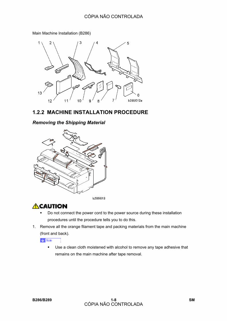
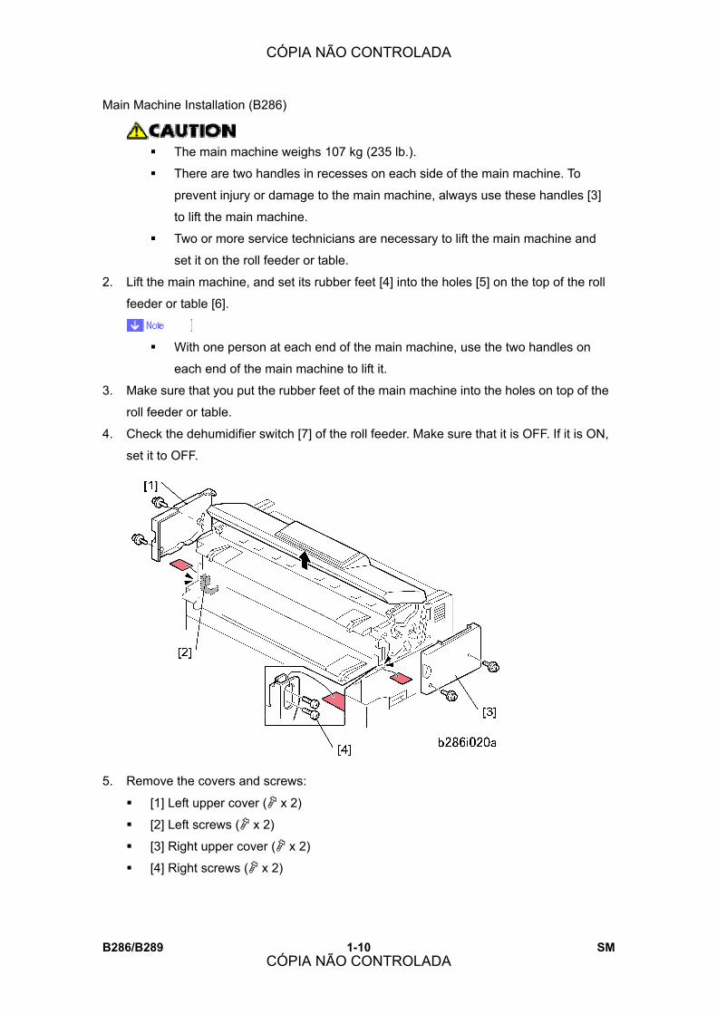
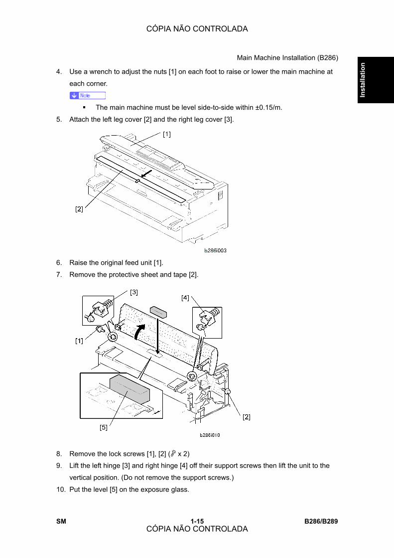
Main Machine Installation (B286)
SM 1-7 B286/B289
Inst
alla
tion
1.2 MAIN MACHINE INSTALLATION (B286)
! Always have this Service Manual with you. The installation procedures are not
shipped with the main machine.
! Never turn the main machine off when the main power LED is lit or flashing. To
avoid damaging the hard disk or memory, press the operation power switch on the
operation panel to turn the power off, wait for the power LED to go off, then turn
the main power switch off.
1.2.1 ACCESSORY CHECK
Check the accessories and their quantities against the table below.
No. Description Q�ty
1 Flat Brush (Fusing Unit Guide Spurs) 1
2 Original Output Guides 6
3 Upper Output Stacker 2
4 Upper Output Guide 1
5 Original Tray 1
6 Operating Instructions (-17, -21) 3
7 Studs 2
8 Panel: Logo 1
9 Cloth � Exposure Glass 1
10 Copy Exit Selection Lever 1
11 Operation Panel Anchor Screws 3
12 Operating Instruction Holder 1
13 Ferrite Core (For Network Cable) 1
CÓPIA NÃO CONTROLADA
CÓPIA NÃO CONTROLADA
Main Machine Installation (B286)
B286/B289 1-8 SM
1.2.2 MACHINE INSTALLATION PROCEDURE
Removing the Shipping Material
! Do not connect the power cord to the power source during these installation
procedures until the procedure tells you to do this.
1. Remove all the orange filament tape and packing materials from the main machine
(front and back).
! Use a clean cloth moistened with alcohol to remove any tape adhesive that
remains on the main machine after tape removal.
CÓPIA NÃO CONTROLADA
CÓPIA NÃO CONTROLADA

Main Machine Installation (B286)
SM 1-9 B286/B289
Inst
alla
tion
Set the Operation Panel Position
You can adjust the position of the operation panel to decrease bright reflections from the
operation panel display..
1. Lift or lower the operation panel [1] to one set of the three sets of holes to set the panel
at the desired angle.
2. Push each anchor screw [2] into its hole (" x 3).
! It is not necessary to tighten the screws.
Setting the Main Machine on the Roll Feeder (B851/B852) or Table (B854)
1. Do not remove the shipping tape from the connectors [1] of the roll feeder [2]. This
prevents damage to the connectors when the main machine is put on top of the roll
feeder.
CÓPIA NÃO CONTROLADA
CÓPIA NÃO CONTROLADA
Main Machine Installation (B286)
B286/B289 1-10 SM
! The main machine weighs 107 kg (235 lb.).
! There are two handles in recesses on each side of the main machine. To
prevent injury or damage to the main machine, always use these handles [3]
to lift the main machine.
! Two or more service technicians are necessary to lift the main machine and
set it on the roll feeder or table.
2. Lift the main machine, and set its rubber feet [4] into the holes [5] on the top of the roll
feeder or table [6].
! With one person at each end of the main machine, use the two handles on
each end of the main machine to lift it.
3. Make sure that you put the rubber feet of the main machine into the holes on top of the
roll feeder or table.
4. Check the dehumidifier switch [7] of the roll feeder. Make sure that it is OFF. If it is ON,
set it to OFF.
5. Remove the covers and screws:
! [1] Left upper cover (" x 2)
! [2] Left screws (" x 2)
! [3] Right upper cover (" x 2)
! [4] Right screws (" x 2)
CÓPIA NÃO CONTROLADA
CÓPIA NÃO CONTROLADA

Main Machine Installation (B286)
SM 1-11 B286/B289
Inst
alla
tion
6. Open the upper unit.
7. Remove:
! [1] Left cover (" x 3)
! [2] Right cover (" x 3)
! [3] Manual feed table (" x 2). Open the drawer of the roll feeder before removing if
the roll feeder is installed.
8. Remove the right transport lock plate [1] (" x 4).
9. Remove the left transport lock plate [2] (" x 4).
CÓPIA NÃO CONTROLADA
CÓPIA NÃO CONTROLADA

Main Machine Installation (B286)
B286/B289 1-12 SM
10. Install the studs [1] on the right side and the left side.
! You must fasten each stud in the upper hole [2] on both sides.
11. Attach the right joint bracket [1] (the spindle [2] must go through the hole). At the same
time, align the plate with the holes for the three screws (blue).
! The joint brackets and screws are provided as accessories with either the Roll
Feeder (B851/B852) or Table (B854).
12. Attach screws , but do not tighten them.
13. While you lift the main machine by its handle [3], set screw in the lower hole of the
keyhole cutout and tighten it.
14. Tighten screws and .
CÓPIA NÃO CONTROLADA
CÓPIA NÃO CONTROLADA

Main Machine Installation (B286)
SM 1-13 B286/B289
Inst
alla
tion
15. Do the above procedure again for the left joint bracket [4].
! The guide plate and screws are provided as accessories with either the Roll
Feeder (B851/B852) or Table (B854).
16. Install the guide plate [1] (" x 2 Blue). Hang the hooks on each end; this puts the plate
in the correct position to be installed.
! The movable guide plates are provided as accessories with either the Roll
Feeder (B851/B852) or Table (B854).
17. Attach the movable guide plates [1] (x6).
! Each plate is the same. It is not possible to install a plate in the incorrect position.
! Attach each plate with the ribbed side down.
! Move the hinges [2] a small distance apart. This allows the tabs to attach easily
CÓPIA NÃO CONTROLADA
CÓPIA NÃO CONTROLADA

Main Machine Installation (B286)
B286/B289 1-14 SM
into the holes.
18. Lift each plate and let it fall, to make sure that they move smoothly on the hinges.
19. Reattach the manual feed table.
20. Reattach the left and right covers.
! The flat-head screw must be attached at the rear side of each cover.
21. Close the upper unit.
Leveling the Main Machine and Attaching Leg Covers
1. Open the toner hopper cover [1].
2. Set a level [2] on the plate [3] of the development unit.
3. Set the shoes , , , under the main machine.
CÓPIA NÃO CONTROLADA
CÓPIA NÃO CONTROLADA
Main Machine Installation (B286)
SM 1-15 B286/B289
Inst
alla
tion
4. Use a wrench to adjust the nuts [1] on each foot to raise or lower the main machine at
each corner.
! The main machine must be level side-to-side within ±0.15/m.
5. Attach the left leg cover [2] and the right leg cover [3].
6. Raise the original feed unit [1].
7. Remove the protective sheet and tape [2].
8. Remove the lock screws [1], [2] (" x 2)
9. Lift the left hinge [3] and right hinge [4] off their support screws then lift the unit to the
vertical position. (Do not remove the support screws.)
10. Put the level [5] on the exposure glass.
CÓPIA NÃO CONTROLADA
CÓPIA NÃO CONTROLADA
Main Machine Installation (B286)
B286/B289 1-16 SM
11. Reattach the hinges and fasten the lock screws removed in Step 8.
Developer
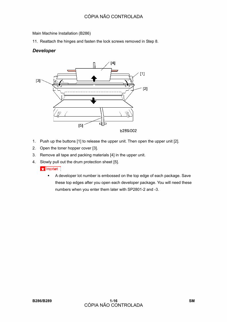
1. Push up the buttons [1] to release the upper unit. Then open the upper unit [2].
2. Open the toner hopper cover [3].
3. Remove all tape and packing materials [4] in the upper unit.
4. Slowly pull out the drum protection sheet [5].
! A developer lot number is embossed on the top edge of each package. Save
these top edges after you open each developer package. You will need these
numbers when you enter them later with SP2801-2 and -3.
CÓPIA NÃO CONTROLADA
CÓPIA NÃO CONTROLADA

Main Machine Installation (B286)
SM 1-17 B286/B289
Inst
alla
tion
5. Open a 1 kg pack of developer and pour it into the development unit.
! Do not add the second pack at this time.
! Open the first pack of developer [1].
! Slowly add the developer from the first pack into the development unit, as you
move the pack from left to right until the pack is empty.
! An equal amount of developer must be spread along the entire open slot of the
development unit.
6. Close the toner hopper cover [2].
7. Close the upper unit [3].
8. Connect the power supply cord. Switch the main power switch on. The main motor
switches on and distributes the developer evenly inside the development unit.
9. Wait about 10 sec.
10. Turn the main power switch off.
11. Disconnect the power cord.
12. Open the upper unit.
13. Open the toner hopper cover.
14. Open the second 1 kg pack of developer, then slowly add it to the development unit.
Move the pack from left to right until it is empty.
15. Use a clean cloth to clean the edges around the slot of the development unit.
16. Close the upper unit.
Toner Cartridge Installation To prepare a toner cartridge for installation
CÓPIA NÃO CONTROLADA
CÓPIA NÃO CONTROLADA
Main Machine Installation (B286)
B286/B289 1-18 SM
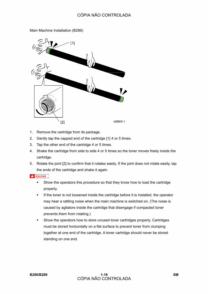
1. Remove the cartridge from its package.
2. Gently tap the capped end of the cartridge [1] 4 or 5 times.
3. Tap the other end of the cartridge 4 or 5 times.
4. Shake the cartridge from side to side 4 or 5 times so the toner moves freely inside the
cartridge.
5. Rotate the joint [2] to confirm that it rotates easily. If the joint does not rotate easily, tap
the ends of the cartridge and shake it again.
! Show the operators this procedure so that they know how to load the cartridge
properly.
! If the toner is not loosened inside the cartridge before it is installed, the operator
may hear a rattling noise when the main machine is switched on. (The noise is
caused by agitators inside the cartridge that disengage if compacted toner
prevents them from rotating.)
! Show the operators how to store unused toner cartridges properly. Cartridges
must be stored horizontally on a flat surface to prevent toner from clumping
together at one end of the cartridge. A toner cartridge should never be stored
standing on one end.
CÓPIA NÃO CONTROLADA
CÓPIA NÃO CONTROLADA

Main Machine Installation (B286)
SM 1-19 B286/B289
Inst
alla
tion
To install a toner cartridge
1. Set the toner cartridge [1] in the main machine.
2. Pull up the tape [2] then pull it across the toner cartridge from right to left to remove the
tape.
3. On the right end of the toner cartridge, push the knob [3] up until it stops.
4. Close the toner hopper cover [4].
5. Switch the main power switch on.
Enter Developer Lot Numbers 1. Go into the SP mode.
2. Do SP2801-2 and 3 to enter the lot numbers.
! Use the soft keyboard on the display panel to enter the lot numbers. (The lot
numbers are embossed on the top edge of each developer pack.) If the
numbers are the same, enter the same number twice.
! You must enter the lot numbers with SP2801-2 and -3 before doing SP2801-1.
The main machine will return an error (�Failed�) if you attempt to do SP2801-1
before SP2801-2 and -3.
Mix Developer and Initialize ID Sensor 1. Next, do SP2801-1 to mix the developer (and initialize the ID sensor). This takes about
5 minutes.
2. Do SP2923. This applies a thin layer of toner to the bare drum.
CÓPIA NÃO CONTROLADA
CÓPIA NÃO CONTROLADA
Main Machine Installation (B286)
B286/B289 1-20 SM
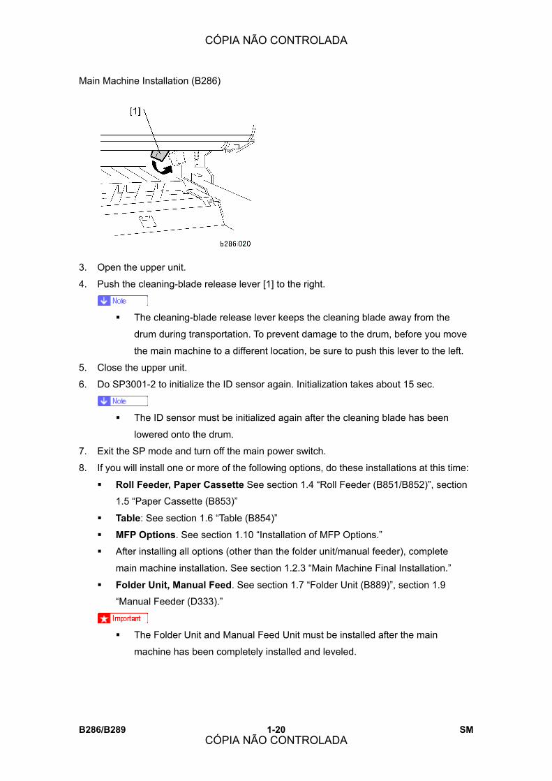
3. Open the upper unit.
4. Push the cleaning-blade release lever [1] to the right.
! The cleaning-blade release lever keeps the cleaning blade away from the
drum during transportation. To prevent damage to the drum, before you move
the main machine to a different location, be sure to push this lever to the left.
5. Close the upper unit.
6. Do SP3001-2 to initialize the ID sensor again. Initialization takes about 15 sec.
! The ID sensor must be initialized again after the cleaning blade has been
lowered onto the drum.
7. Exit the SP mode and turn off the main power switch.
8. If you will install one or more of the following options, do these installations at this time:
! Roll Feeder, Paper Cassette See section 1.4 �Roll Feeder (B851/B852)�, section
1.5 �Paper Cassette (B853)�
! Table: See section 1.6 �Table (B854)�
! MFP Options. See section 1.10 �Installation of MFP Options.�
! After installing all options (other than the folder unit/manual feeder), complete
main machine installation. See section 1.2.3 �Main Machine Final Installation.�
! Folder Unit, Manual Feed. See section 1.7 �Folder Unit (B889)�, section 1.9
�Manual Feeder (D333).�
! The Folder Unit and Manual Feed Unit must be installed after the main
machine has been completely installed and leveled.
CÓPIA NÃO CONTROLADA
CÓPIA NÃO CONTROLADA

Main Machine Installation (B286)
SM 1-21 B286/B289
Inst
alla
tion
1.2.3 MAIN MACHINE FINAL INSTALLATION
Select the Tray Paper Size and Type 1. Push [User Tools] > �System Settings� > �Tray Paper Settings.�
! Selections are shown only for installed options. If you installed all the options,
you will see �Tray Paper Size: Tray 1� (1st Roll), �Tray Paper Size: Tray 2� (2nd
Roll), and �Tray Paper Size: Tray 3� (Cassette).
2. Select the paper size for each tray and bypass tray.
3. Select the paper type for each tray and bypass tray.
Testing the Main Machine Circuit Breaker
! Follow the procedure below to test the operation of the circuit breaker. This must
be done at installation and at least once a year after installation.
1. Plug the main machine power cord into its power source and make sure that the main
machine power is off.
! Do not turn on the main machine. The main machine must be off.
2. Remove the rear cover [1] ("x2)
3. Use the tip of a small screwdriver to depress the breaker test button.
! The breaker switch should flip from �|� to �O.� This indicates that the breaker switch
is operating normally.
! If the breaker switch does not flip to �O�, the switch must be replaced.
CÓPIA NÃO CONTROLADA
CÓPIA NÃO CONTROLADA

Main Machine Installation (B286)
B286/B289 1-22 SM
4. Push the breaker lever to display �|� again and reset the main machine for normal
operation.
! The main machine power will not turn on if the switch [2] remains at �O.�
5. Reattach the rear cover.
Main Machine Accessories
1. To attach the original tray [1], attach the top first, then the bottom as shown.
2. Make sure the four tabs (x4) are completely engaged.
3. Attach both upper output stackers [1].
4. Attach the copy exit selection lever [2].
5. Attach the original output guides [3] (x6).
6. Attach the upper output guide [4].
CÓPIA NÃO CONTROLADA
CÓPIA NÃO CONTROLADA
Main Machine Installation (B286)
SM 1-23 B286/B289
Inst
alla
tion
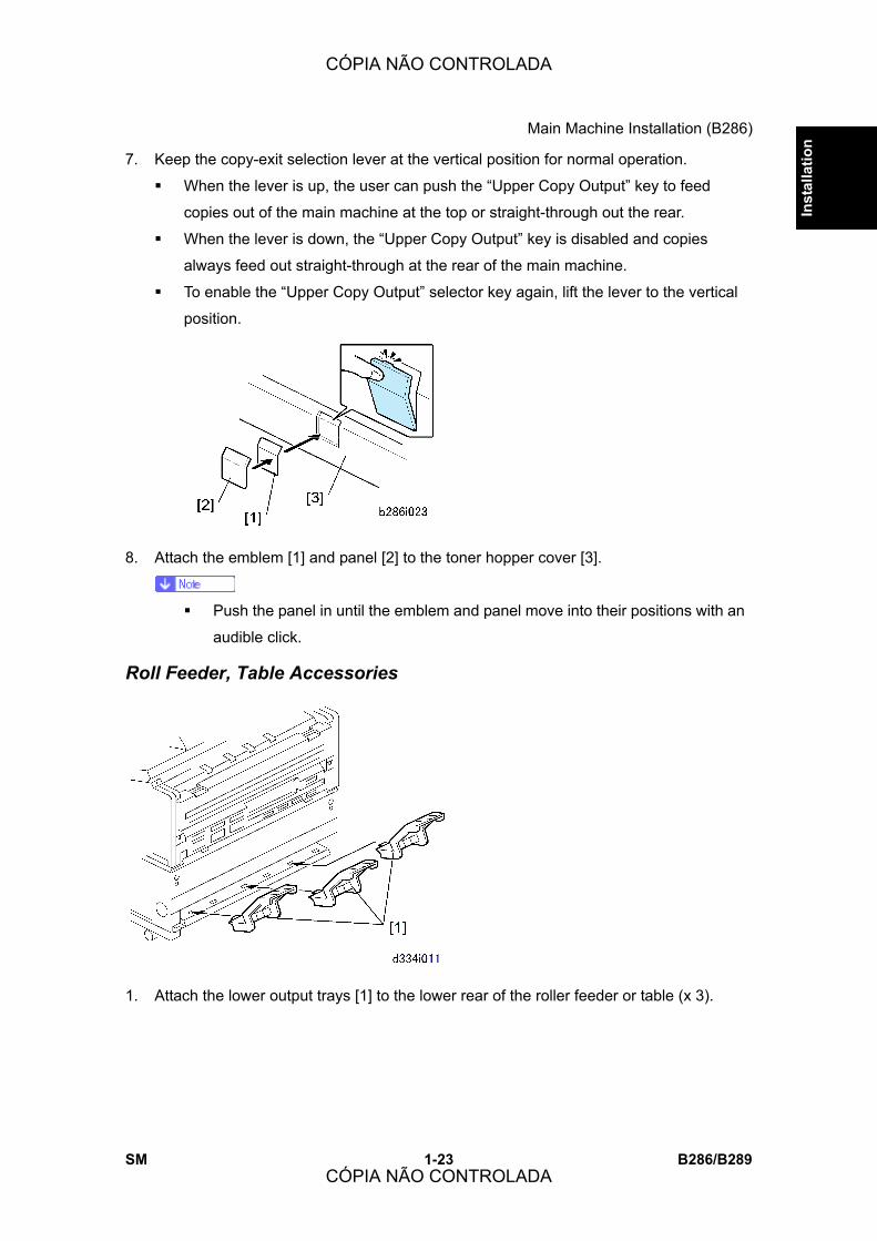
7. Keep the copy-exit selection lever at the vertical position for normal operation.
! When the lever is up, the user can push the �Upper Copy Output� key to feed
copies out of the main machine at the top or straight-through out the rear.
! When the lever is down, the �Upper Copy Output� key is disabled and copies
always feed out straight-through at the rear of the main machine.
! To enable the �Upper Copy Output� selector key again, lift the lever to the vertical
position.
8. Attach the emblem [1] and panel [2] to the toner hopper cover [3].
! Push the panel in until the emblem and panel move into their positions with an
audible click.
Roll Feeder, Table Accessories
1. Attach the lower output trays [1] to the lower rear of the roller feeder or table (x 3).
CÓPIA NÃO CONTROLADA
CÓPIA NÃO CONTROLADA

Main Machine Installation (B286)
B286/B289 1-24 SM
! The lines and numbers embossed on the back of the main machine (see the
upper left of the above diagrams) show where to position the exit guide plates
for different paper widths.
2. Position the right exit guide plate [1] as shown, then attach it with its magnet.
3. Position the left exit guide plate [2] as shown, then attach it with its magnet.
4. Do a test print to confirm that the paper exits the main machine straightly and smoothly
between the guide plates.
CÓPIA NÃO CONTROLADA
CÓPIA NÃO CONTROLADA
Main Machine Installation (B286)
SM 1-25 B286/B289
Inst
alla
tion
Copy Check Scan an original to confirm that the main machine operates correctly.
1. Set an original or test pattern face down on the original feed tray.
2. After about 1 second, the main machine pulls the original, stops for 1 second, then
starts to feed it.
3. Do a sample copy from the roller feeder and paper cassette if these options are
installed.
4. If the copied image is not in the correct position, do SP2941 (IPU Test Pattern) and
print pattern 11. For instructions on leading edge and side-to-side adjustments, see
section 3.11 �SP Adjustments.�
Paper Roll Adjustments
SP No. Name Comment
1001-1 Leading Edge Registration � 1st Roll B851/B852
1001-2 Leading Edge Registration � 2nd Roll B852
1002-1 Side-to-Side Registration � 1st Roll B851/B852
1002-2 Side-to-SideRegistration � 2nd Roll B852
Paper Cassette Adjustments
SP No. Name
1001-3 Leading Edge Registration � Cassette (B853)
1002-3 Side-to-Side Registration � Cassette (B853)
Enable Onboard NIB, USB Functions Do SP5985 (Device Setting) to enable the onboard NIB and USB features built into the GW
Controller board.
! The default setting of SP5985 is �0� (Disable). This SP must be set to �1� in order
to use the built-in NIB and USB functions.
1.2.4 MOVING THE MACHINE
! If you will move the main machine to a different building, open the paper feed section
CÓPIA NÃO CONTROLADA
CÓPIA NÃO CONTROLADA
Main Machine Installation (B286)
B286/B289 1-26 SM
and push the cleaning blade lever to the left. This keeps the cleaning blade away from
the drum while you move the main machine.
! If you will move the main machine to a different location in the same building, it is not
necessary to set the lever to the left, and it is not necessary to disconnect the main
machine from the roll feeder or table.
! Always push low on the roll feeder or table to move the main machine. If you
do not do this, you can twist and possibly cause damage to the main machine.
Do not push on the main machine while it is installed on top of the roll feeder
or table.
! To prepare the main machine for transport to a different building, disconnect the main
machine and the roller feeder (or table). Attach the drawer to the frame with tape, or
the roll feeder drawer will fall out of the table frame.
! Lift the main machine with one person on each end of the main machine. Be sure to
use the handles in recesses on the sides of the main machine.
! To prevent developer and toner spill, never tilt the main machine more than 30° from
the horizontal.
CÓPIA NÃO CONTROLADA
CÓPIA NÃO CONTROLADA

Original Hanger (D311)
SM 1-27 B286/B289
Inst
alla
tion
1.3 ORIGINAL HANGER (D311)
The optional original hanger is attached to the bypass feed table on the front of the main
machine.
1.3.1 ACCESSORY CHECK
Check the accessories and their quantities against the table below.
No. Description Q�ty
1 Original Hangers 2
1.3.2 INSTALLATION
1. Attach one original hanger [1] to the bypass feed table [2].
2. Attach the other original hanger [3] to the bypass feed table.
CÓPIA NÃO CONTROLADA
CÓPIA NÃO CONTROLADA
Roll Feeder (B851/B852)
B286/B289 1-28 SM
1.4 ROLL FEEDER (B851/B852)
! The Roll Feeder (B851/B852) is required in order to use the Printer Option
(D320/D344).
1.4.1 ACCESSORY CHECK
Check the accessories and their quantities against the table below.
No. Description Q�ty
1 Lower Output Trays 3
2 Leg Covers 2
3 Movable Guides 6
4 Shoes 4
5 Joint Brackets (Left, Right) 2
6 Exit Guide Plates 2
7 Screws (Cosmetic Silver) 4
8 Screws (Blue) 9
9 Harness Brackets 2
10 Mylars � Wide 2
11 Mylars � Narrow 2
12 Nylon clamp 1
13 Harness clamp 1
14 Ferrite Core (for B275) 1
15 Guide Plate 1
CÓPIA NÃO CONTROLADA
CÓPIA NÃO CONTROLADA

Roll Feeder (B851/B852)
SM 1-29 B286/B289
Inst
alla
tion
1.4.2 ROLL FEEDER INSTALLATION PROCEDURE
Setting the Main Machine on the Roll Feeder
1. Do not remove the shipping tape from the connectors [1] of the roll feeder [2]. This
prevents damage to the connectors when the main machine is put on top of the roll
feeder.
! The main machine weighs 107 kg (235 lb.).
! There are two handles in recesses on each side of the main machine. To
prevent injury or damage to the main machine, always use these handles [3]
to lift the main machine.
! Two or more service technicians are necessary to lift the main machine and
CÓPIA NÃO CONTROLADA
CÓPIA NÃO CONTROLADA

Roll Feeder (B851/B852)
B286/B289 1-30 SM
set it on the roll feeder.
2. Lift the main machine, and set its rubber feet [4] into the holes [5] on the top of the roll
feeder.
! With one person at each end of the main machine, use the two handles on
each end of the main machine to lift it.
3. Make sure that you put the rubber feet of the main machine into the holes on top of the
roll feeder.
4. Check the dehumidifier switch [6] of the roll feeder. Make sure that it is OFF. If it is ON,
set it to OFF.
Opening the Roll Feeder and Removing Shipping Material
! The drawer of the roll feeder is locked and cannot be opened until the main
machine is set on top of the roll feeder.
! Do not try to open the drawer of the roll feeder until after you set the main machine
on top of the roll feeder.
1. Open the drawer [1] of the roll feeder.
2. Remove the spring lock plate [2] (" x 2).
3. Remove the roll paper holders [3] and cardboard packing [4].
! Roll Feeder B851 has 2 holders, and Roll Feeder B852 has 4 holders (shown
above).
4. Remove other tape or packing material in the roll feeder.
5. Remove the shipping lock plate [5] (" x 2).
CÓPIA NÃO CONTROLADA
CÓPIA NÃO CONTROLADA
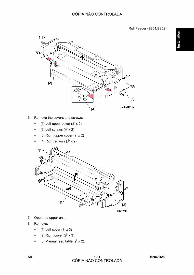
Roll Feeder (B851/B852)
SM 1-31 B286/B289
Inst
alla
tion
6. Remove the covers and screws:
! [1] Left upper cover (" x 2)
! [2] Left screws (" x 2)
! [3] Right upper cover (" x 2)
! [4] Right screws (" x 2)
7. Open the upper unit.
8. Remove:
! [1] Left cover (" x 3)
! [2] Right cover (" x 3)
! [3] Manual feed table (" x 2).
CÓPIA NÃO CONTROLADA
CÓPIA NÃO CONTROLADA

Roll Feeder (B851/B852)
B286/B289 1-32 SM
9. Remove the right transport lock plate [1] (" x 4).
10. Remove the left transport lock plate [2] (" x 4).
11. Install the studs [1] on the right side and the left side.
! You must fasten each stud in the upper hole [2] on both sides.
CÓPIA NÃO CONTROLADA
CÓPIA NÃO CONTROLADA
Roll Feeder (B851/B852)
SM 1-33 B286/B289
Inst
alla
tion
12. Attach the right joint bracket [1] (the spindle [2] must go through the hole). At the same
time, align the plate with the holes for the three screws (blue).
! The joint brackets and screws are provided as accessories with the roll feeder.
13. Attach screws , but do not tighten them.
14. While you lift the main machine by its handle [3], set screw in the lower hole of the
keyhole cutout and tighten it.
15. Tighten screws and .
16. Do the above procedure again for the left joint bracket [4].
! The guide plate and screws are provided as accessories with the roll feeder.
CÓPIA NÃO CONTROLADA
CÓPIA NÃO CONTROLADA
Roll Feeder (B851/B852)
B286/B289 1-34 SM
17. Install the guide plate [1] (" x 2 Blue). Hang the hooks on each end; this puts the plate
in the correct position to be installed.
! The movable guide plates are provided as accessories with the roll feeder.
18. Attach the movable guide plates [1] (x6).
! Each plate is the same. It is not possible to install a plate in the incorrect position.
! Attach each plate with the ribbed side down.
! Move the hinges [2] a small distance apart. This allows the tabs attach easily into
the holes.
19. Lift each plate and let it fall, to make sure that they move smoothly on the hinges.
20. Reattach the manual feed table.
21. Reattach the left and right covers.
! The flat-head screw must be attached at the rear side of each cover.
22. Close the upper unit.
CÓPIA NÃO CONTROLADA
CÓPIA NÃO CONTROLADA

Roll Feeder (B851/B852)
SM 1-35 B286/B289
Inst
alla
tion
Leveling the Main Machine and Attaching Leg Covers
1. Open the toner hopper cover [1].
2. Set a level [2] on the plate [3] of the development unit.
3. Set the shoes , , , under the main machine.
4. Use a wrench to adjust the nuts [1] on each foot to raise or lower the main machine at
each corner.
! The main machine must be level side-to-side within ±0.15/m.
5. Attach the left leg cover [2] and the right leg cover [3].
CÓPIA NÃO CONTROLADA
CÓPIA NÃO CONTROLADA

Roll Feeder (B851/B852)
B286/B289 1-36 SM
6. Raise the original feed unit [1].
7. Remove the protective sheet and tape [2].
8. Remove the lock screws [1], [2] (" x 2)
9. Lift the left hinge [3] and right hinge [4] off their support screws then lift the unit to the
vertical position. (Do not remove the support screws.)
10. Put the level [5] on the exposure glass.
11. Use a wrench to adjust the nuts on each foot to lift or lower the main machine at each
corner.
! The main machine must be level side-to-side within ±0.15/m.
12. Reattach the hinges and fasten the lock screws removed in Step 8.
CÓPIA NÃO CONTROLADA
CÓPIA NÃO CONTROLADA

Roll Feeder (B851/B852)
SM 1-37 B286/B289
Inst
alla
tion
Connecting the Main Machine and Roll Feeder
1. Remove the rear cover [1] of the main machine ("x2).
2. Remove the cover of the controller unit [2] ("x1).
3. Remove the ground plate [1] (" x 3).
! Open the paper exit cover (C1) and paper exit unit (C2) together to remove
screw (the vertical screw).
4. Remove the shield cover [2] (" x 8).
CÓPIA NÃO CONTROLADA
CÓPIA NÃO CONTROLADA

Roll Feeder (B851/B852)
B286/B289 1-38 SM
5. Remove the rear plate [1] of the roll feeder (" x 2).
6. Remove the metal brackets [2], [3] (" x 1 each). Discard these brackets and screws.
7. Remove the shipping tape from the roll feeder harnesses between the bottom of the
main machine and top of the roll feeder.
8. Route the harness (# x 1) through bracket [4] then attach the bracket (" x 2). (Use
one screw from the accessories.)
9. Route the harness (# x 2) through bracket [5] and then attach the bracket (" x 2).
(Use one screw from the accessories).
10. Connect the left harness [1] to CN103 on the PSU (# x 1, & x 1).
11. Connect the right harness [2] to CN220 and CN221 on the MCU (# x 2, & x 3).
CÓPIA NÃO CONTROLADA
CÓPIA NÃO CONTROLADA
Roll Feeder (B851/B852)
SM 1-39 B286/B289
Inst
alla
tion
12. Reattach:
! [1] Shield cover (" x 8)
! [2] Ground plate (" x3)
! Roll feeder rear plate(# x 2)
! When you reattach the ground plate, make sure that the harness wires [3]
below are not pinched between the bottom of the frame and bottom of the
ground plate.
13. Reattach:
! Controller box cover
! Rear cover
! Open and close the paper exit cover C1 and paper exit unit C2 together to
confirm that the rear cover is installed correctly. If the paper exit cover does
not open properly, remove the rear cover and install it again.
CÓPIA NÃO CONTROLADA
CÓPIA NÃO CONTROLADA

Roll Feeder (B851/B852)
B286/B289 1-40 SM
Attaching the Narrow Mylars to the Main Machine
1. Find the 5th space from the left end of the rear cover.
2. Use a clean cloth, moistened with a small amount of alcohol, to clean this area and the
bottom edge of the cover.
3. Remove the tape from each end of one of the narrow mylars.
4. Attach one end to the top edge of the cover .
! The top edge must be flat and parallel to the edge of the cover. The right edge
of the mylar must be parallel to ridge .
5. Attach the other end of the mylar to the bottom edge of the cover .
6. Do this procedure again to attach the other narrow mylar to the right side of the cover.
CÓPIA NÃO CONTROLADA
CÓPIA NÃO CONTROLADA
Roll Feeder (B851/B852)
SM 1-41 B286/B289
Inst
alla
tion
Attaching the Wide Mylars to the Back of the Roll Feeder
1. On the left side of the rear plate [1], find the straight line [2] and , patterns [3].
2. Use a clean cloth, moistened with a small amount of alcohol, to clean this area and the
bottom edge of the cover.
3. Remove the tape from each end of one of the wide mylars.
4. Align the end with the narrow tape with the top edge [4] of the rear plate. Make sure
that the right edge is parallel to the vertical lines on the plate, then push down.
5. Turn the end with the wide tape against the plate, and align its corner [5] with the
inverted �L� pattern embossed on the plate, then push it against the rear plate.
6. Make sure that the tape surfaces are pushed fully against the rear plate.
7. Reattach the rear cover of the main machine (" x 2).
CÓPIA NÃO CONTROLADA
CÓPIA NÃO CONTROLADA

Roll Feeder (B851/B852)
B286/B289 1-42 SM
Securing the Power Cord
1. Clean the rear plate [1] with alcohol.
2. Attach the harness clamp [2].
3. Clamp the power cord [3] to the roll feeder (" x 1).
Installing the Paper Rolls If you will install the optional paper cassette (see section 1.5 �Paper Cassette (B853)�), do
this before you install the paper rolls.
If you do not install the paper cassette first, you must remove Roll 2 before you can install
the optional paper cassette.
! To install the paper rolls, follow the instructions on the decal on the top edge of the
roll feeder drawer.
CÓPIA NÃO CONTROLADA
CÓPIA NÃO CONTROLADA
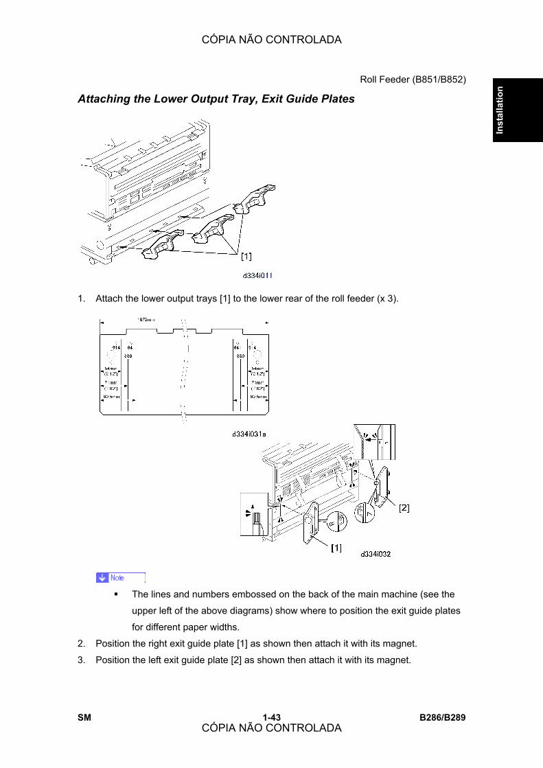
Roll Feeder (B851/B852)
SM 1-43 B286/B289
Inst
alla
tion
Attaching the Lower Output Tray, Exit Guide Plates
1. Attach the lower output trays [1] to the lower rear of the roll feeder (x 3).
! The lines and numbers embossed on the back of the main machine (see the
upper left of the above diagrams) show where to position the exit guide plates
for different paper widths.
2. Position the right exit guide plate [1] as shown then attach it with its magnet.
3. Position the left exit guide plate [2] as shown then attach it with its magnet.
CÓPIA NÃO CONTROLADA
CÓPIA NÃO CONTROLADA

Roll Feeder (B851/B852)
B286/B289 1-44 SM
4. Do a test print to confirm that the paper exits the main machine straightly and smoothly
between the guide plates.
Entering the Cut Length Adjustment 1. Do the settings for SP1920. These are the cut length SP settings for the rolls (there are
two settings for each roll).
2. Check the label on the right side of the roll feeder drawer. Do the settings written on the
label.
Roll SP No. Name
Roll 1 1920-111 Cut Length Adjustment: 1st Roll:297 mm:Plain Paper
Roll 1 1920-115 Cut Length Adjustment: 1st Roll:1189 mm:Plain Paper
Roll 2 1920-211 Cut Length Adjustment: 2nd Roll:297 mm:Plain Paper
Roll 2 1920-215 Cut Length Adjustment: 2nd Roll:1189 mm:Plain Paper
3. Switch the main power switch off, then switch it on again.
Setting Paper Sizes/Types for the Tray 1 (1st Roll), Tray 2 (2nd Roll) 1. Push [User Tools]> �System Settings�> �Tray Paper Settings�> �Tray Paper Size: Tray
1�, �Tray Paper Size: Tray 2.�
2. Select the paper size for Tray 1 and Tray 2.
3. Push �Next�> �Paper Type: Tray 1�, �Paper Type: Tray2
4. Select the paper type for Tray 1 and Tray 2.
CÓPIA NÃO CONTROLADA
CÓPIA NÃO CONTROLADA

Paper Cassette (B853)
SM 1-45 B286/B289
Inst
alla
tion
1.5 PAPER CASSETTE (B853)
! The Paper Cassette (B853) is installed in the Roll Feeder (B851/B852).
1.5.1 ACCESSORY CHECK
Check the accessories and their quantities the table below.
No. Description Q�ty
1 Paper Cassette Unit 1
2 Screws 4
3 Harness Clamps 4
4 Paper Cassette (Universal Type) 1
1.5.2 PAPER CASSETTE INSTALLATION PROCEDURE
! Confirm that the machine is switched off and that the power cord is disconnected
from the power source before doing this procedure.
CÓPIA NÃO CONTROLADA
CÓPIA NÃO CONTROLADA
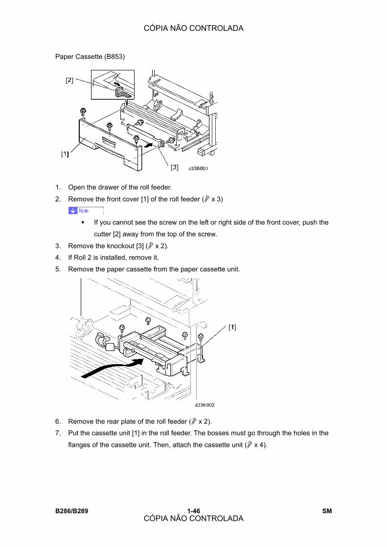
Paper Cassette (B853)
B286/B289 1-46 SM
1. Open the drawer of the roll feeder.
2. Remove the front cover [1] of the roll feeder (" x 3)
! If you cannot see the screw on the left or right side of the front cover, push the
cutter [2] away from the top of the screw.
3. Remove the knockout [3] (" x 2).
4. If Roll 2 is installed, remove it.
5. Remove the paper cassette from the paper cassette unit.
6. Remove the rear plate of the roll feeder (" x 2).
7. Put the cassette unit [1] in the roll feeder. The bosses must go through the holes in the
flanges of the cassette unit. Then, attach the cassette unit (" x 4).
CÓPIA NÃO CONTROLADA
CÓPIA NÃO CONTROLADA

Paper Cassette (B853)
SM 1-47 B286/B289
Inst
alla
tion
8. From the front, remove the board cover [1] (" x 2).
9. Connect the paper-cassette-unit connectors [2] (# x 2) to the roll feeder.
10. From the front, attach the harness clamps , , , .
11. Route the connector cable through the open clamps, then close the clamps (& x6).
12. Reattach the board cover, front cover, and rear plate of the roll feeder.
13. Reinstall the paper rolls, and close the drawer of the roll feeder.
14. Put the paper cassette in the paper cassette unit.
15. Set the Paper Size and Type for the Paper Cassette
! Push [User Tools]> �System Settings�> �Tray Paper Settings�> �Tray Paper Size:
Tray 3�
! Select the paper size for the paper cassette..
! Push �Next�> �Paper Type: Tray 3�
! Select the paper type for the paper cassette. (Default: Plain Paper).
CÓPIA NÃO CONTROLADA
CÓPIA NÃO CONTROLADA

Table (B854)
B286/B289 1-48 SM
1.6 TABLE (B854)
1.6.1 ACCESSORY CHECK
Check the accessories and their quantities the table below.
No. Description Q�ty
1 Lower Output Trays 3
2 Leg Covers 2
3 Shoes 4
4 Joint Brackets (Left, Right) 2
5 Exit Guide Plates 2
6 Screws 9
7 Mylars � Wide 2
8 Mylars � Narrow 2
9 Guide Plate 1
10 Nylon Clamp 1
11 Harness Clamp 1
12 Stopper Bracket (for inch paper sizes) 1
CÓPIA NÃO CONTROLADA
CÓPIA NÃO CONTROLADA

Table (B854)
SM 1-49 B286/B289
Inst
alla
tion
1.6.2 INSTALLATION PROCEDURE
! Confirm that the machine is switched off and that the power cord is disconnected
from the power source before doing this procedure.
Setting the Main Machine on the Table
! The main machine weighs 107 kg (235 lb.).
! There are two handles in recesses on each side of the main machine. To prevent
injury or damage to the main machine, always use these handles [1] to lift the main
machine.
! Two or more service technicians are necessary to lift the main machine and set it
on the table.
1. Lift the main machine, and set its rubber feet [2] into the holes [3] on the top of the
table [4].
! With one person at each end of the main machine, use the two handles on
each end of the main machine to lift it.
2. Make sure that you put the rubber feet of the main machine into the holes on top of the
table.
CÓPIA NÃO CONTROLADA
CÓPIA NÃO CONTROLADA

Table (B854)
B286/B289 1-50 SM
Leveling the Main Machine and Attaching Leg Covers Make the main machine level. Attach the leg covers. Follow the instructions in �Leveling the
Main Machine and Attaching Leg Covers.�
Attaching the Guide Plate
! Keep the power cord disconnected while you do this procedure.
1. Install the guide plate [1] (" x 2 Blue). Hang the hooks on each ends; this puts the
plate in the correct position to be installed.
Connecting the Main Machine and Table
CÓPIA NÃO CONTROLADA
CÓPIA NÃO CONTROLADA
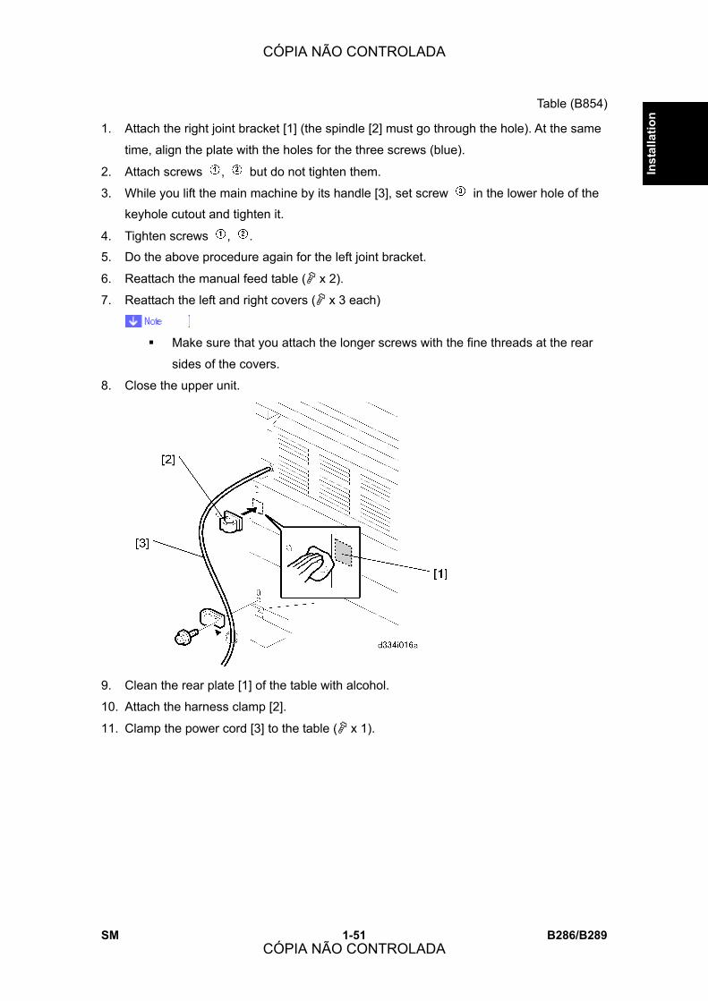
Table (B854)
SM 1-51 B286/B289
Inst
alla
tion
1. Attach the right joint bracket [1] (the spindle [2] must go through the hole). At the same
time, align the plate with the holes for the three screws (blue).
2. Attach screws , but do not tighten them.
3. While you lift the main machine by its handle [3], set screw in the lower hole of the
keyhole cutout and tighten it.
4. Tighten screws , .
5. Do the above procedure again for the left joint bracket.
6. Reattach the manual feed table (" x 2).
7. Reattach the left and right covers (" x 3 each)
! Make sure that you attach the longer screws with the fine threads at the rear
sides of the covers.
8. Close the upper unit.
9. Clean the rear plate [1] of the table with alcohol.
10. Attach the harness clamp [2].
11. Clamp the power cord [3] to the table (" x 1).
CÓPIA NÃO CONTROLADA
CÓPIA NÃO CONTROLADA

Table (B854)
B286/B289 1-52 SM
Attach the Narrow Mylars to the Main Machine
1. If the rear cover is attached to the main machine, remove it (" x 2).
2. Find the 5th space from the left end of the rear cover.
3. Use a clean cloth, moist with a small quantity of alcohol, to clean this area and the
bottom edge of the cover.
4. Remove the tape from each end of one of the narrow mylars.
5. Attach one end to the top edge of the cover .
! The top edge must be flat and parallel to the edge of the cover. The right edge
of the mylar must be parallel to ridge .
6. Attach the other end of the mylar to the bottom edge of the cover .
7. Do this procedure again to attach the other narrow mylar to the right side of the cover.
8. Reattach the cover to the back of the main machine (" x 2).
CÓPIA NÃO CONTROLADA
CÓPIA NÃO CONTROLADA

Table (B854)
SM 1-53 B286/B289
Inst
alla
tion
Attach the Wide Mylars to the Back of the Table
1. On the left side of the rear plate [1], find the straight line [2] and, patterns [3].
2. Use a clean cloth, moistened with a small amount of alcohol, to clean this area and the
bottom edge of the cover.
3. Remove the tape from each end of one of the wide mylars.
4. Align the end with the narrow tape with the top edge [4] of the rear plate. Make sure
that the right edge is parallel to the vertical lines on the plate, then push down.
5. Turn the end with the wide tape against the plate, and align its corner [5] with the
inverted �L� pattern embossed on the plate , then push it against the rear plate.
6. Make sure that the tape surfaces are pushed fully against the rear plate.
CÓPIA NÃO CONTROLADA
CÓPIA NÃO CONTROLADA

Table (B854)
B286/B289 1-54 SM
Attaching the Stopper Brackets
! This stopper bracket is only for machines in North America that use inch paper
sizes.
1. Remove the stoppers [1] (% x 2 each).
2. Use a clean cloth soaked in alcohol to clean the surfaces [2] where the stopper
brackets [3] will be attached.
3. Remove the double-sided tape [4] from the rear of each bracket.
4. Install each bracket and stopper on the arms.
5. Lock each stopper in the correct position (% x 2 each).
Table Accessories
CÓPIA NÃO CONTROLADA
CÓPIA NÃO CONTROLADA
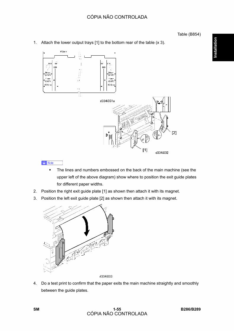
Table (B854)
SM 1-55 B286/B289
Inst
alla
tion
1. Attach the lower output trays [1] to the bottom rear of the table (x 3).
! The lines and numbers embossed on the back of the main machine (see the
upper left of the above diagram) show where to position the exit guide plates
for different paper widths.
2. Position the right exit guide plate [1] as shown then attach it with its magnet.
3. Position the left exit guide plate [2] as shown then attach it with its magnet.
4. Do a test print to confirm that the paper exits the main machine straightly and smoothly
between the guide plates.
CÓPIA NÃO CONTROLADA
CÓPIA NÃO CONTROLADA
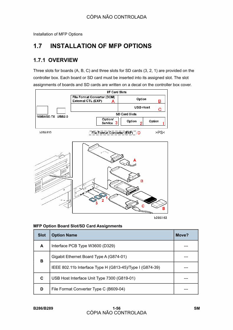
Installation of MFP Options
B286/B289 1-56 SM
1.7 INSTALLATION OF MFP OPTIONS
1.7.1 OVERVIEW
Three slots for boards (A, B, C) and three slots for SD cards (3, 2, 1) are provided on the
controller box. Each board or SD card must be inserted into its assigned slot. The slot
assignments of boards and SD cards are written on a decal on the controller box cover.
MFP Option Board Slot/SD Card Assignments
Slot Option Name Move?
A Interface PCB Type W3600 (D329) ---
Gigabit Ethernet Board Type A (G874-01) --- B
IEEE 802.11b Interface Type H (G813-45)/Type I (G874-39) ---
C USB Host Interface Unit Type 7300 (G819-01) ---
D File Format Converter Type C (B609-04) ---
CÓPIA NÃO CONTROLADA
CÓPIA NÃO CONTROLADA

Installation of MFP Options
SM 1-57 B286/B289
Inst
alla
tion
Slot Option Name Move?
Printer Option Type W3600 (D320) Yes
Scanner Option Type W3600 (D321) Yes 1
Data Overwrite Security Unit Type D (B735-18) Yes
Printer Option Type W3600 (D320): TIFF/GL Filter No*1
Browser Unit Type C (B828-03) No 2
VM Card Type E (D338-01, -02, -03) No
Service
! Firmware Update
! NVRAM Data Download/Upload
! Application Move/Undo
Browser Unit Type C (B828-03) No
3
VM Card Type E (D338-01, -02, -03) No
*1: Due to copyright restrictions, these options cannot be moved to another SD card
1.7.2 ENABLING THE ONBOARD FEATURES
The NIB and USB support features are built into the GW controller board. However, these
features cannot be used until they have been enabled with SP5985 (Device Setting).
Before installing any other options in this section, do SP5985 and make sure each item is
set to �1.�
CÓPIA NÃO CONTROLADA
CÓPIA NÃO CONTROLADA
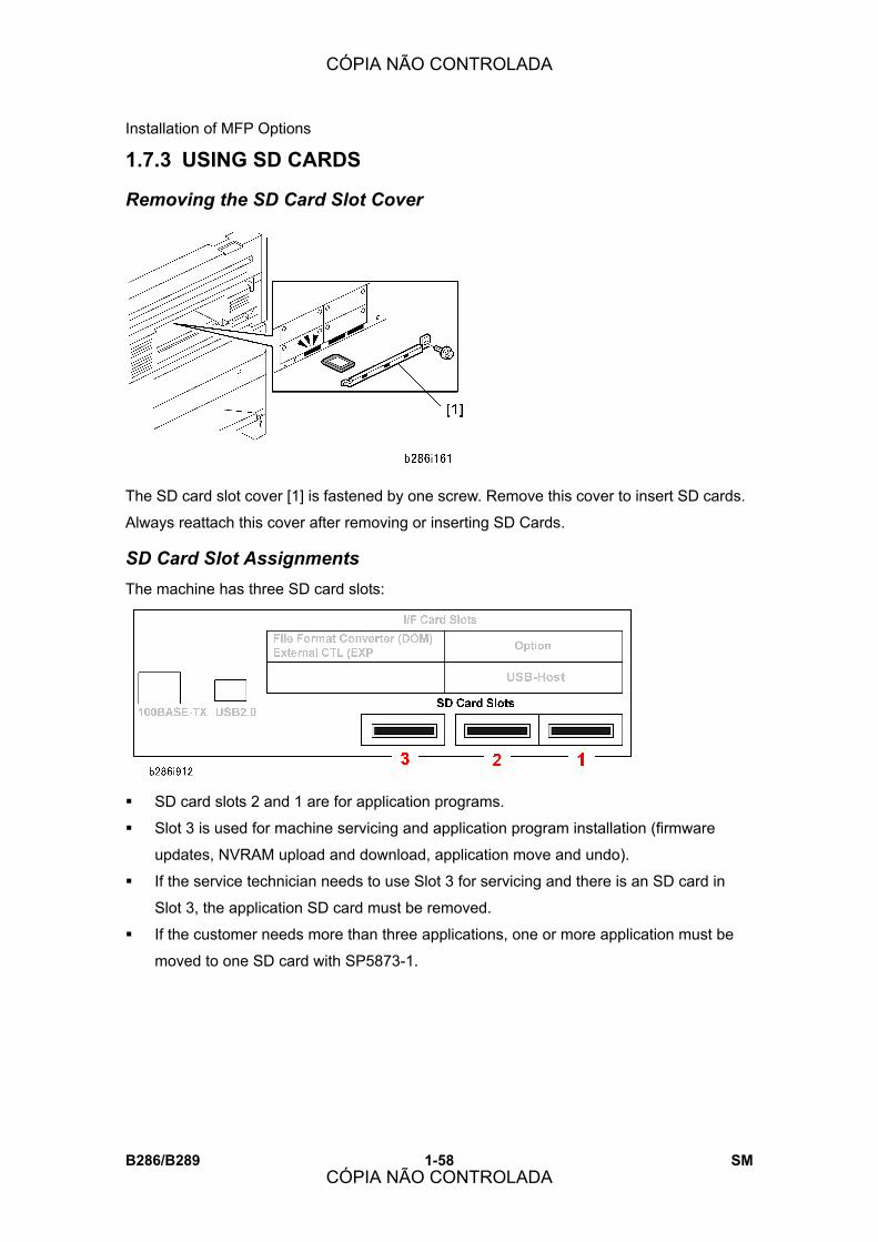
Installation of MFP Options
B286/B289 1-58 SM
1.7.3 USING SD CARDS
Removing the SD Card Slot Cover
The SD card slot cover [1] is fastened by one screw. Remove this cover to insert SD cards.
Always reattach this cover after removing or inserting SD Cards.
SD Card Slot Assignments The machine has three SD card slots:
! SD card slots 2 and 1 are for application programs.
! Slot 3 is used for machine servicing and application program installation (firmware
updates, NVRAM upload and download, application move and undo).
! If the service technician needs to use Slot 3 for servicing and there is an SD card in
Slot 3, the application SD card must be removed.
! If the customer needs more than three applications, one or more application must be
moved to one SD card with SP5873-1.
CÓPIA NÃO CONTROLADA
CÓPIA NÃO CONTROLADA
Installation of MFP Options
SM 1-59 B286/B289
Inst
alla
tion
Slot Application
1 2 3
Comment
Printer Option Type W3600 (D320) Yes No No
Scanner Option Type W3600 (D321) Yes No No Can move to D320
Data Overwrite Security Type D
(B735-18)
Yes No No Can move to D320 or
D321
Printer Option Type W3600 (B320):
TIFF/GL Filter
No Yes No
Browser Unit Type C (B828-03) No Yes Yes
VM Card Type E (D338-01, 02, -03) No Yes Yes
Either Slot
Service:
! Firmware update
! NVRAM Data Download/Upload
! Application Move/Undo
No No Yes
Restrictions and Precautions on the Use of SD Cards ! When an application is moved from one SD card to another SD card, the
authentication data is transferred with the application program to the target SD card.
! Do not use an SD card if it has been used with a computer or other device. (The SD
card may not operate correctly.)
! The original SD card received with purchase of the application program is the only
evidence that the customer is licensed to use the application. For this reason, the
original SD card should be stored at the work site as proof of purchase by the customer.
Also, the service technician may occasionally need to check the dates and version
numbers SD cards during troubleshooting.
! After an SD card has been used to combine applications on one card, it cannot be
used for any other purpose.
! Always make sure that the write-protect switch is OFF before uploading data to an SD
card. It is very easy to accidentally turn on the write-protect switch when inserting and
removing an SD card.
! To remove an SD card from its slot, push it in gently to release it then pull it out of its
slot.
CÓPIA NÃO CONTROLADA
CÓPIA NÃO CONTROLADA

Installation of MFP Options
B286/B289 1-60 SM
Application Move �Move Exec� (SP5873-1) moves one application program from the original SD card to
another SD card. The application program is moved from Slot 3 to Slot 1 (or Slot 2).
1. Turn off the main power switch.
2. Remove the SD card slot cover ("x1).
3. Insert the original SD card with the application in Slot 3.
4. Insert the SD card to receive the application in Slot 1.
! The SD card to receive the moved application can be set in Slot 2, but in this
case Slot 1 must be empty. (The application always moves the application to
Slot 1 by default if there are SD cards in both Slot 1 and Slot 2.)
5. Turn on the main power switch.
6. Enter the SP mode and do SP5873-1 �Move Exec.�
7. Follow the messages on the operation panel to complete the procedure.
8. Exit the SP mode.
9. Turn off the main power switch.
10. Remove the original SD card from Slot 3.
11. Leave the other SD card in Slot 1 or Slot 2.
12. Turn on the main power switch.
13. Check that the application program runs normally.
14. Tell the customer to store the original SD card in a safe place.
Undo Exec �Undo Exec� (SP5873-2) restores an application to its original SD card. The application is
moved from Slot 3 to Slot 1 (or Slot 2).
CÓPIA NÃO CONTROLADA
CÓPIA NÃO CONTROLADA

Installation of MFP Options
SM 1-61 B286/B289
Inst
alla
tion
1. Turn off the main power switch.
2. Remove the SD card slot cover ("x1).
3. Insert the SD card that currently holds the application in Slot 3.
4. Insert the original SD card to receive the restored application in Slot 1.
! The SD card to receive the restored application can be set in Slot 2, but in this
case Slot 1 must be empty. (The application always moves to Slot 1 by default
if there are SD cards in both Slot 1 and Slot 2.)
5. Turn on the main power switch.
6. Enter the SP mode and do SP5873-2 �Undo Exec.�
7. Follow the messages on the operation panel to complete the procedure.
8. Exit the SP mode.
9. Turn off the main power switch.
10. Remove both SD cards.
11. Insert the SD card with the restored application in Slot 1 or 2.
12. Turn on the main power switch.
13. Check that the application operates normally.
1.7.4 PRINTER OPTION TYPE W3600 (D320)
! The Roll Feeder (B851/B852) is required in order to use the Printer Option (D320).
Accessories Check the accessories and their quantities against the table below.
Description Qt�y
1. SD Card: Printer 1
1. SD Card: TIFF/GL Filter 1
CÓPIA NÃO CONTROLADA
CÓPIA NÃO CONTROLADA
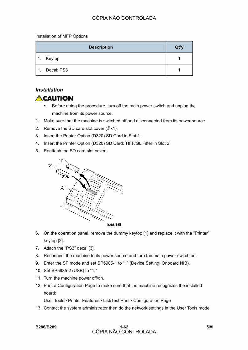
Installation of MFP Options
B286/B289 1-62 SM
Description Qt�y
1. Keytop 1
1. Decal: PS3 1
Installation
! Before doing the procedure, turn off the main power switch and unplug the
machine from its power source.
1. Make sure that the machine is switched off and disconnected from its power source.
2. Remove the SD card slot cover ("x1).
3. Insert the Printer Option (D320) SD Card in Slot 1.
4. Insert the Printer Option (D320) SD Card: TIFF/GL Filter in Slot 2.
5. Reattach the SD card slot cover.
6. On the operation panel, remove the dummy keytop [1] and replace it with the �Printer�
keytop [2].
7. Attach the �PS3� decal [3].
8. Reconnect the machine to its power source and turn the main power switch on.
9. Enter the SP mode and set SP5985-1 to �1� (Device Setting: Onboard NIB).
10. Set SP5985-2 (USB) to �1.�
11. Turn the machine power off/on.
12. Print a Configuration Page to make sure that the machine recognizes the installed
board:
User Tools> Printer Features> List/Test Print> Configuration Page
13. Contact the system administrator then do the network settings in the User Tools mode
CÓPIA NÃO CONTROLADA
CÓPIA NÃO CONTROLADA

Installation of MFP Options
SM 1-63 B286/B289
Inst
alla
tion
(IP address, subnet mask, etc.)
! If the customer intends to use the Ratio external controller from the PC side, this
GW controller printer SD card must be removed from the main machine.
1.7.5 SCANNER OPTION TYPE W3600 (D321)
Accessories Check the accessories and their quantities against the table below.
Description Qt�y
1. SD Card: Scanner 1
1. Keytop 1
Installation
! Before doing the procedure, turn off the main power switch and unplug the
machine from its power source.
1. Make sure that the machine is switched off and disconnected from its power source.
2. Remove the SD card slot cover ("x1).
3. Insert the scanner SD card into Slot 1.
! If the printer SD card is in Slot 1, do SP5873-1 to move the scanner
application to the printer application SD card.
4. Reattach the SD card slot cover ("x1).
5. On the operation panel, remove the dummy keytop and replace it with the �Scanner�
keytop.
CÓPIA NÃO CONTROLADA
CÓPIA NÃO CONTROLADA

Installation of MFP Options
B286/B289 1-64 SM
6. Reconnect the machine to its power source and turn the main power switch ON.
7. Enter the SP mode and set SP5985-1 to “1” (Device Setting: Onboard NIB).
8. Set SP5985-2 (Device Setting: Onboard USB) to “1.”
9. Do a memory clear for the Scanner option (SP5801-009). After the Memory Clear, if
the customer wishes to use a language other than English, change the email language
setting in User Tools .
10. Turn the machine power OFF/ON.
11. Print a Configuration Page to make sure that the machine recognizes the installed
board:
User Tools> Printer Features> List/Test Print> Configuration Page
If the customer intends to use the Ratio external controller from the PC side, the
GW controller scanner option can be used and does not need to be removed from
the main machine.
If the GW printer option has been moved to the scanner SD card, be sure to
remove the printer option SD card.
1.7.6 FILE FORMAT CONVERTER TYPE C (B609-04)
Accessories Check the accessories and their quantities against the table below.
Description Q’ty
1. File Format Converter PCB 1
Installation
Before doing the procedure, turn off the main power switch and unplug the
machine from its power source.
1. Make sure that the machine is switched off and disconnected from its power source.
2. If the folder unit is installed, disconnect it and pull it away from the main machine.
⇒
Rev. 09/2007
CÓPIA NÃO CONTROLADA
CÓPIA NÃO CONTROLADA

Installation of MFP Options
SM 1-65 B286/B289
Inst
alla
tion
3. Remove:
! [A] Rear cover ("x2)
! [B] Controller cover ("x1)
4. Remove:
! [A] Ground plate ("x3)
! Open covers C1 and C2 together to remove the vertical screw.
! [B] PCB shield cover ("x8)
CÓPIA NÃO CONTROLADA
CÓPIA NÃO CONTROLADA

Installation of MFP Options
B286/B289 1-66 SM
5. Remove bracket [1] ("x2). Keep these screws.
6. Remove cover [1] and discard it ("x2). Keep the screws.
7. Attach the bracket [2] removed in Step 5 to the PCB ("x2).
8. Disconnect the connectors [1] (#x3).
9. Slowly insert the board [2] then fasten it ("x2).
Reinstallation
! Be sure to reconnect the connectors (#x3).
CÓPIA NÃO CONTROLADA
CÓPIA NÃO CONTROLADA
Installation of MFP Options
SM 1-67 B286/B289
Inst
alla
tion
! After reattaching the rear cover, open the covers C1 and C2 to confirm that they open
smoothly. If C1 and C2 do not open smoothly, the rear cover is not installed correctly.
Remove it and reinstall it.
1.7.7 INTERFACE PCB (D329)
! The Interface PCB (D329) is required in order to use the external printer option
(D344).
Accessories Check the accessories and their quantities against the table below.
Description Qt�y
1. Interface PCB 1
1. Interface Cable 1
1. Nylon Clamp 1
1. Harness Clamp 1
1. Screws (M4x8) 1
Installation
! Before doing the procedure, turn off the main power switch and unplug the
machine from its power source.
1. Make sure that the machine is switched off and disconnected from its power source.
CÓPIA NÃO CONTROLADA
CÓPIA NÃO CONTROLADA

Installation of MFP Options
B286/B289 1-68 SM
2. Remove cover of Slot A [1] ("x2).
3. Insert the interface PCB [2] (Knob screws x2).
4. Connect the interface cable [3].
5. Attach the interface cable to the back of the main unit [1] (Cable hooks x2)
6. Clean the rear plate [2] with alcohol.
7. Attach harness clamp [3].
8. Close the clamp round the harness cable [4].
9. Connect the other end of the interface cable to the server PC (Printer Controller
RW3600).
CÓPIA NÃO CONTROLADA
CÓPIA NÃO CONTROLADA

Installation of MFP Options
SM 1-69 B286/B289
Inst
alla
tion
! The GW printer option cannot be used while this interface PCB is installed in the
main machine.
1.7.8 IEEE802.11B INTERFACE UNIT TYPE H (G813-45)/TYPE I (G874-39)
Accessories Check the accessories and their quantities against the table below.
Description Qt�y
1. Wireless LAN Card 1
1. Adapter Board 1
1. Cover Cap 1
Installation
! Before doing the procedure, turn off the main power switch and unplug the
machine from its power source.
1. Make sure that the machine is switched off and disconnected from its power source.
2. Remove the cover [1] of Slot B (" x 2).
3. Insert the adapter board [2] into Slot B (Knob " x 2).
4. Insert the wireless LAN card [3] into the adapter board [2].
5. Attach the cap [4].
6. Reconnect the machine to the power source and turn the main power switch on.
7. Print a Configuration Page to confirm correct installation:
User Tools> Printer Features> List/Test Print> Configuration Page
CÓPIA NÃO CONTROLADA
CÓPIA NÃO CONTROLADA
Installation of MFP Options
B286/B289 1-70 SM
1.7.9 GIGABIT ETHERNET BOARD TYPE A (G874-01)
Accessories Check the accessories and their quantities against the table below.
Description Qt�y
1. Gigabit Ethernet Board 1
1. Ferrite Core 1
1. Standard USB Connector Cap 1
1. Standard LAN Connector Cap 1
! To use the Gigabit Ethernet Board, SP5985-2 must be set to �1� to enable the NIC
and USB functions.
! When the Gigabit Ethernet Board is installed, the standard Ethernet board and
standard USB board can no longer be used. Two caps are provided to cover the
standard Ethernet and USB connectors. This prevents accidental reconnection of
the cables while the Gigabit Ethernet board is installed in the machine.
! Touch a metal surface to discharge any static electricity from your hands before
you handle the board.
Installation
! Before doing the procedure, turn off the main power switch and unplug the
machine from its power source.
1. Make sure that the machine is switched off and disconnected from its power source.
CÓPIA NÃO CONTROLADA
CÓPIA NÃO CONTROLADA

Installation of MFP Options
SM 1-71 B286/B289
Inst
alla
tion
2. Disconnect the cables of the standard Ethernet board and standard USB board.
3. Cover the standard connection points with the caps to prevent accidental reconnection
of the standard cables.
4. Remove the cover of Slot B [1] (" x 2).
5. Insert the Gigabit Ethernet Board [2] into Slot B (Knob " x 2).
6. Attach the ferrite core provided with the Gigabit Ethernet Board to the end of the cable
[1] to be attached to the network.
7. Attach the ferrite core provided with the main machine to the end of the cable [2] to be
attached to the main machine.
! Attach both cores 4.5 cm (about 2 in.) from each end of the cord.
8. Reconnect the machine to its power source and turn the main power switch on.
9. Do SP5985-2 and set to �1� to enable the NIC and USB functions.
CÓPIA NÃO CONTROLADA
CÓPIA NÃO CONTROLADA
Installation of MFP Options
B286/B289 1-72 SM
10. Turn the machine�s power off/on.
11. Print a Configuration Page to make sure that the machine recognizes the installed
board for USB2.0:
User Tools > Printer Features > List/Test Print > Configuration Page
1.7.10 DATA OVERWRITE SECURITY UNIT TYPE D (B735-18)
Accessories Check the accessories and their quantities against the table below.
Description Qt�y
1. Data Overwrite Security SD Card 1
1. Operating Instructions CD-ROM 1
Before You Begin� 1. Make sure that the Data Overwrite Security unit SD card is the correct type for the
machine. The correct type for this machine is type �D.�
! Do this now. If you install any version other than type �D�, you will have to
replace the NVRAM and do this installation procedure again.
2. Make sure that the following items are not at the factory default settings:
! Supervisor login password
! Administrator login name
! Administrator login password
! These settings must be set up by the customer before the Data Overwrite
Security unit can be installed.
3. Make sure that �Admin. Authentication� is on:
[User Tools]> �System Settings�> �Administrator Tools�> �Administrator Authentication
Management�> �Admin. Authentication�> �On�
If this setting is �Off�, tell the customer that this setting must be �On� before you can do
the installation procedure.
4. Make sure that �Administrator Tools� is selected and enabled:
[User Tools] > �System Settings� > �Administrator Tools�> �Administrator Authentication
Management�> �Available Settings
CÓPIA NÃO CONTROLADA
CÓPIA NÃO CONTROLADA

Installation of MFP Options
SM 1-73 B286/B289
Inst
alla
tion
! �Available Settings� is not displayed until Step 2 is done. If this setting is not
selected, tell the customer that this setting must be selected before you can
do the installation procedure.
Seal Check and Removal
1. Turn off the main power switch and disconnect the power supply cord.
2. Check the two box seals [1] on the corners of the box.
! Make sure that the seals are attached at both corners.
! The surfaces of the tapes must be blank.
! If you see �VOID� on the tapes, do not install the components in the box, contact
your sales division.
3. If the surfaces of the tapes do not show �VOID�, remove them from the corners of the
box.
! Do not install the application if you see �VOID.� The �VOID� marks [2] become
visible only after the tape is removed. This guarantees that the box has not
been opened since it was shipped.
Installation
! Before doing the procedure, turn off the main power switch and unplug the
machine from its power source.
1. Make sure that the machine is switched off and disconnected from its power source.
2. Disconnect the network cable.
3. Turn the main power switch on.
4. Turn the operation switch and main power switch off.
CÓPIA NÃO CONTROLADA
CÓPIA NÃO CONTROLADA
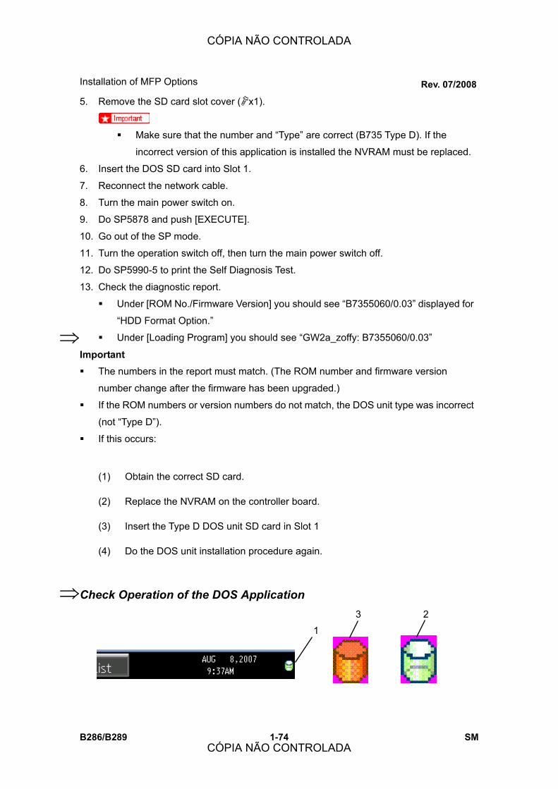
Installation of MFP Options
B286/B289 1-74 SM
5. Remove the SD card slot cover ( x1).
Make sure that the number and “Type” are correct (B735 Type D). If the
incorrect version of this application is installed the NVRAM must be replaced.
6. Insert the DOS SD card into Slot 1.
7. Reconnect the network cable.
8. Turn the main power switch on.
9. Do SP5878 and push [EXECUTE].
10. Go out of the SP mode.
11. Turn the operation switch off, then turn the main power switch off.
12. Do SP5990-5 to print the Self Diagnosis Test.
13. Check the diagnostic report.
Under [ROM No./Firmware Version] you should see “B7355060/0.03” displayed for
“HDD Format Option.”
Under [Loading Program] you should see “GW2a_zoffy: B7355060/0.03”
Important The numbers in the report must match. (The ROM number and firmware version
number change after the firmware has been upgraded.)
If the ROM numbers or version numbers do not match, the DOS unit type was incorrect
(not “Type D”).
If this occurs:
(1) Obtain the correct SD card.
(2) Replace the NVRAM on the controller board.
(3) Insert the Type D DOS unit SD card in Slot 1
(4) Do the DOS unit installation procedure again.
Check Operation of the DOS Application
⇒
Rev. 07/2008
1 3 2
⇒
CÓPIA NÃO CONTROLADA
CÓPIA NÃO CONTROLADA
Installation of MFP Options
SM 1-75 B286/B289
Inst
alla
tion
1. Turn �Auto Erase Memory Setting� on:
[User Tools]> �System Settings�> �Administrator Tools�> �Auto Erase Memory
Setting�> �On�
2. Exit User Tools.
3. Check the display and make sure that the overwrite erase icon [1] is displayed.
4. Make a Sample Copy.
5. Check the overwrite erase icon.
! The icon [2] changes to [3] when job data is stored in the hard disk.
! The icon resumes its normal shape [2] after a data overwrite has completed.
1.7.11 USB HOST INTERFACE UNIT TYPE 7300 (G819-01)
Accessories Check the accessories and their quantities against the table below.
Description Qt�y
1. USB Host Interface Board 1
Installation
! Before doing the procedure, turn off the main power switch and unplug the
machine from its power source.
1. Make sure that the machine is switched off and disconnected from its power source.
2. Remove the cover of Slot C [1] (" x 2).
3. Insert the board [2] into Slot C (Knob " x 2).
4. Reconnect the machine to its power source and turn the main power switch on.
5. Print a Configuration Page to make sure that the machine recognizes the installed
CÓPIA NÃO CONTROLADA
CÓPIA NÃO CONTROLADA

Installation of MFP Options
B286/B289 1-76 SM
board:
User Tools> Printer Features> List/Test Print> Configuration Page
1.7.12 BROWSER UNIT TYPE C (B828-03)
Accessories Check the accessories and their quantities against the table below.
Description Qt�y
1. Browser Unit Type C SD Card 1
1. Keytops (EU/NA) 2
Installation
! Before doing the procedure, turn off the main power switch and unplug the
machine from its power source.
1. Make sure that the machine is switched off and disconnected from its power source.
2. Remove the SD card slot cover ("x1).
3. Insert the SD card into Slot 2 or 3.
! If you push in the SD Card, this releases it for removal. Make sure that the SD
Card is inserted and locked in place. If it is partially out of the slot, push it in
gently until it locks.
4. Reconnect the machine and turn it on.
5. Push [User Tools].
6. Push [Login/Logout] on the operation panel
7. Login with the administrator user name and password.
8. Touch [Extended Feature Settings].
9. Touch [Extended Feature Settings] again.
10. Touch [SD Card].
11. Touch the [Browser] line.
12. Under �Install to:� touch [Machine HDD] then touch [Next]
13. When you see �Ready to Install�, check the information on the screen to confirm the
previous selection.
14. Touch [OK]. You will see �Installing�� then �Completed.�
15. Touch [Exit] twice to return to the copy screen.
CÓPIA NÃO CONTROLADA
CÓPIA NÃO CONTROLADA
Installation of MFP Options
SM 1-77 B286/B289
Inst
alla
tion
16. Turn the machine power off/on.
! Do not remove the SC card from Slot C3.
17. Open the Browser screen from the �Extended Feature Settings� in User Tools.
A message appears if the installation was successful: �The MFP Browser was
successfully installed.�
18. Turn the main machine off.
19. Remove the SD card for the Browser unit from Slot 2 or 3, then reattach the SD card
slot cover.
20. On the operation panel remove the dummy keytop and replace it with the �Others�
keytop.
1.7.13 VM CARD TYPE E (D338-01, -02, -03)
Accessories Check the accessories and their quantities against the table below.
Description Qt�y
VM Card 1
Decal 1
Installation
! Before doing the procedure, turn off the main power switch and unplug the
machine from its power source.
1. Remove SD card slot cover ("x1).
2. Insert the SD card into SD card slot 2 or 3.
CÓPIA NÃO CONTROLADA
CÓPIA NÃO CONTROLADA

Installation of MFP Options
B286/B289 1-78 SM
! If you push in the SD Card, this releases it for removal. Make sure that the SD
Card is inserted and locked in place. If it is partially out of the slot, push it in
gently until it locks.
3. Switch the machine on.
4. Attach the decal.
CÓPIA NÃO CONTROLADA
CÓPIA NÃO CONTROLADA

Rear Stacker (D312)
SM 1-79 B286/B289
Inst
alla
tion
1.8 REAR STACKER (D312)
The rear stacker is an optional device installed on the back of the Roll Feeder (B851/B852).
1.8.1 ACCESSORIES
Check the accessories and their quantities against the table below.
No. Description Qty
1. Copy Tray Holder 1
2. Guide Mylar 1
3. Rear Copy Tray 3
4. Screws (M4x8) 4
⇒
Rev. 10/2007
CÓPIA NÃO CONTROLADA
CÓPIA NÃO CONTROLADA

Rear Stacker (D312)
B286/B289 1-80 SM
1.8.2 INSTALLATION
5. Attach:
! [1] Copy tray holder ("x4)
! [2] Rear copy tray (x3)
! [3] Guide mylar (x1) ) to center of copy tray
CÓPIA NÃO CONTROLADA
CÓPIA NÃO CONTROLADA

PREVENTIVE MAINTENANCE
CÓPIA NÃO CONTROLADA
CÓPIA NÃO CONTROLADA

CÓPIA NÃO CONTROLADA
CÓPIA NÃO CONTROLADA

PM Table
SM 2-1 B286/B289
Prev
entiv
e M
aint
enan
ce
2. PREVENTIVE MAINTENANCE
2.1 PM TABLE
Key for the PM Table
A = Adjust, C = Clean, I = Inspect, L = Lubricate, R = Replace
! Units of measure in the PM Interval column: Metric: 1,000 meters, Feet: 1,000 feet
2.1.1 MAIN MACHINE (B286)
PM Interval Description Q�ty
Metric Feet PM Comments
Scanner
Original Feed Rollers 5.5 18.0 C Damp cloth
Original Exit Rollers 5.5 18.0 C
Platen Plate 5.5 18.0 C
Original Width, Set,
Registration, Exit Sensors
33.0 108.0 C Blower brush
Exposure Glass 5.5 18.0 C Damp cloth or glass
cleaner
CIS Surfaces 5.5 18.0 C Alcohol or lens paper
Development
Developer (1,000 g) 2 27.5 90.0 R Replace if necessary.
Development Filter 5.5 18.0 C
Development Roller Gear 5.5 18.0 I
Dry cloth or vacuum
cleaner
Development Lower Casing 5.5 18.0 C Dry
CÓPIA NÃO CONTROLADA
CÓPIA NÃO CONTROLADA
PM Table
B286/B289 2-2 SM
PM Interval Description Q�ty
Metric Feet PM Comments
Cleaning
Cleaning Blade 1 11.0 36.0 I/R Replace if necessary.
Cleaning Entrance Seal 11.0 36.0 C Lens paper or dry cloth.
Side Seals 11.0 36.0 C
Inside Cleaning Unit 11.0 36.0 I Dry cloth or vacuum
cleaner
Used Toner Bottle 5.5 18.0 C Empty used toner
Registration
Registration Rollers 5.5 18.0 C Damp cloth
Paper Registration Sensor 5.5 18.0 C Blower brush
Around the Drum
Charge Corona Wire 11.0 36.0 R Lens paper
Corona Wire Cleaner 1 5.5 18.0 R
Charge Corona Casing 5.5 18.0 C Damp cloth
Grid Wires 5.5 18.0 C
Transfer Corona Wire 1 11.0 36.0 R
Separation Corona Wire 1 11.0 36.0 R
Lens paper
T&S Unit Casing and
Guides
5.5 18.0 C Lens paper or dry cloth.
Quenching Lamp 5.5 18.0 C Lens paper or dry cloth
ID Sensor 5.5 18.0 C
Pick-off Pawl 5.5 18.0 C
Dry cloth; do SP3001 2 to
initialize the sensor after
you clean it.
CÓPIA NÃO CONTROLADA
CÓPIA NÃO CONTROLADA
PM Table
SM 2-3 B286/B289
Prev
entiv
e M
aint
enan
ce
PM Interval Description Q�ty
Metric Feet PM Comments
LPH (LED Print Heads) 5.5 18.0 C Lens paper or alcohol.
After cleaning, touch to
discharge static.
Important: Use no other
chemical cleaners.
Fusing Unit
Hot Roller 1 27.5 90.0 R Replace if necessary.
Fusing Cleaning Roller 1 27.5 90.0 R Always replace with hot
roller.
Hot Roller Bushings 1 27.5 90.0 R Always replace with hot
roller. Lubricate.
Pressure Roller 1 33.0 108.0 R Replace if necessary.
Hot Roller Strippers 5.5 18.0 C Dry cloth.
Pressure Roller Strippers 5.5 18.0 C
Hot Roller Thermistor 11.0 36.0 C
Pressure Roller Thermistor 11.0 36.0 C
Fusing Exit Guide Plate 5.5 18.0 C
Paper Junction Gate 5.5 18.0 C
Fusing Entrance Guide
Spurs
5.5 18.0 C Cleaner brush
Alcohol, dry cloth at every
visit. (See section 2.2
�Cleaning the Entrance
Spurs�)
Fusing Exit Rollers 11.0 36.0 C Damp cloth
Fusing Exit Sensor 5.5 18.0 C Blower brush
CÓPIA NÃO CONTROLADA
CÓPIA NÃO CONTROLADA
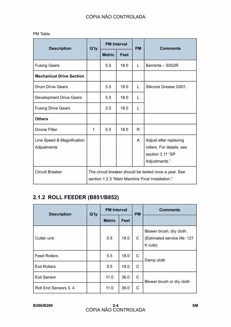
PM Table
B286/B289 2-4 SM
PM Interval Description Q�ty
Metric Feet PM Comments
Fusing Gears 5.5 18.0 L Barrierta � S552R
Mechanical Drive Section
Drum Drive Gears 5.5 18.0 L
Development Drive Gears 5.5 18.0 L
Fusing Drive Gears 5.5 18.0 L
Silicone Grease G501.
Others
Ozone Filter 1 5.5 18.0 R
Line Speed & Magnification
Adjustments
A Adjust after replacing
rollers. For details, see
section 3.11 �SP
Adjustments.�
Circuit Breaker The circuit breaker should be tested once a year. See
section 1.2.3 �Main Machine Final Installation.�
2.1.2 ROLL FEEDER (B851/B852)
PM Interval Comments Description Q�ty
Metric Feet PM
Cutter unit 5.5 18.0 C
Blower brush, dry cloth.
(Estimated service life: 127
K cuts)
Feed Rollers 5.5 18.0 C
Exit Rollers 5.5 18.0 C Damp cloth
Exit Sensor 11.0 36.0 C
Roll End Sensors 3, 4 11.0 36.0 C Blower brush or dry cloth
CÓPIA NÃO CONTROLADA
CÓPIA NÃO CONTROLADA

PM Table
SM 2-5 B286/B289
Prev
entiv
e M
aint
enan
ce
PM Interval Comments Description Q’ty
Metric Feet PM
(EXP)
2.1.3 PAPER CASSETTE (B853)
PM Interval PM Comments Description Q’ty
K Prints
Feed Roller 1 C/R
Friction Pad 1 C/R Replace if necessary
Grip Rollers C
Relay Sensor
40
C Blower brush or dry cloth
⇒
Rev. 10/2007
CÓPIA NÃO CONTROLADA
CÓPIA NÃO CONTROLADA

PM Table
B286/B289 2-6 SM
Page intentionally left blank.
Rev. 10/2007
⇒
CÓPIA NÃO CONTROLADA
CÓPIA NÃO CONTROLADA

Cleaning the Entrance Spurs
SM 2-7 B286/B289
Prev
entiv
e M
aint
enan
ce
2.2 CLEANING THE ENTRANCE SPURS
1. Open the upper unit.
2. Retrieve the flat brush from [1] from its storage location.
3. Use the flat brush to clean the 5 entrance spurs [2].
! Be sure to return the flat brush to its storage location when you are finished.
CÓPIA NÃO CONTROLADA
CÓPIA NÃO CONTROLADA
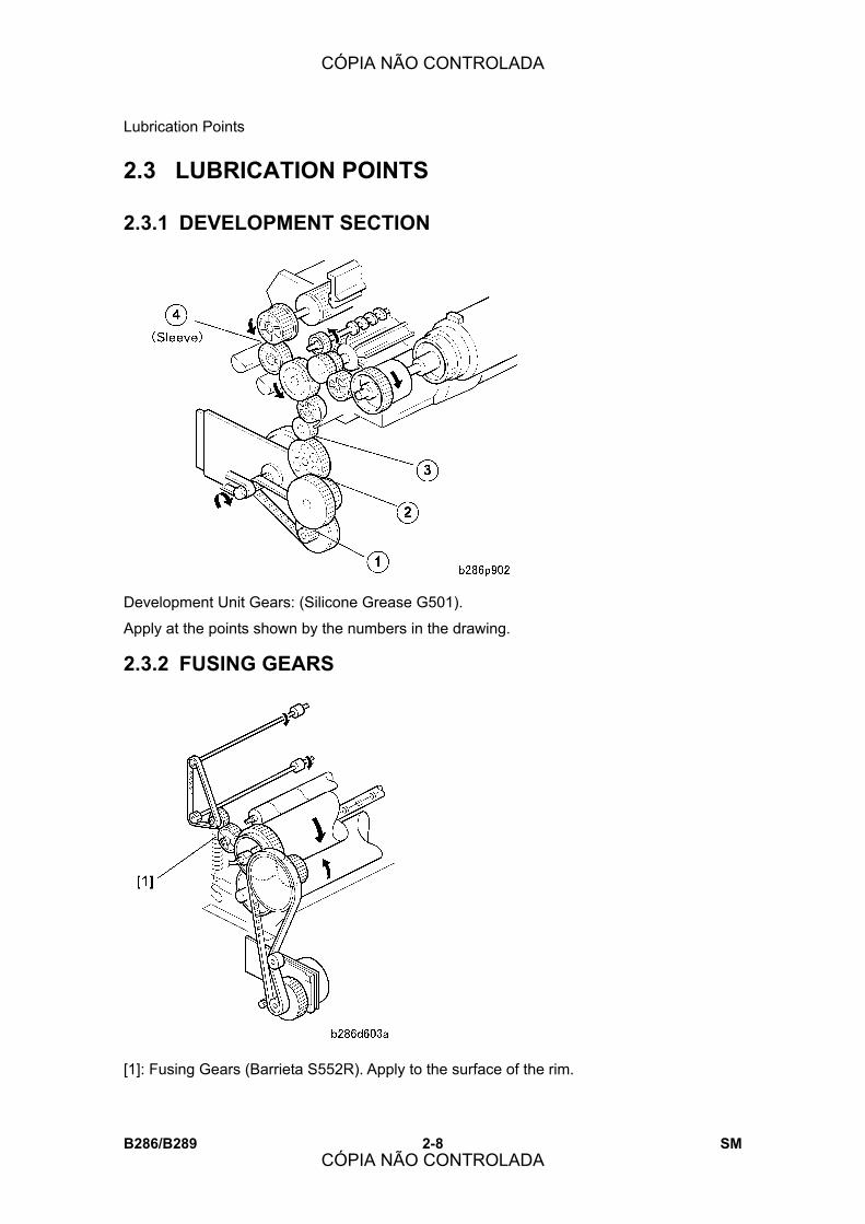
Lubrication Points
B286/B289 2-8 SM
2.3 LUBRICATION POINTS
2.3.1 DEVELOPMENT SECTION
Development Unit Gears: (Silicone Grease G501).
Apply at the points shown by the numbers in the drawing.
2.3.2 FUSING GEARS
[1]: Fusing Gears (Barrieta S552R). Apply to the surface of the rim.
CÓPIA NÃO CONTROLADA
CÓPIA NÃO CONTROLADA
REPLACEMENT AND ADJUSTMENT
CÓPIA NÃO CONTROLADA
CÓPIA NÃO CONTROLADA

CÓPIA NÃO CONTROLADA
CÓPIA NÃO CONTROLADA
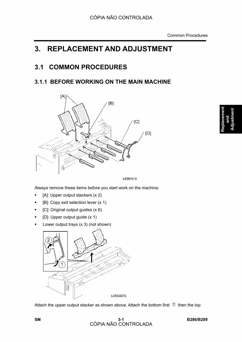
Common Procedures
SM 3-1 B286/B289
Rep
lace
men
t an
d A
djus
tmen
t
3. REPLACEMENT AND ADJUSTMENT
3.1 COMMON PROCEDURES
3.1.1 BEFORE WORKING ON THE MAIN MACHINE
Always remove these items before you start work on the machine:
! [A]: Upper output stackers (x 2)
! [B]: Copy exit selection lever (x 1)
! [C]: Original output guides (x 6)
! [D]: Upper output guide (x 1)
! Lower output trays (x 3) (not shown)
Attach the upper output stacker as shown above. Attach the bottom first then the top
CÓPIA NÃO CONTROLADA
CÓPIA NÃO CONTROLADA

Common Procedures
B286/B289 3-2 SM
.
Reinstallation
! The copy-exit selection lever must be up. In this position, the user can set the paper
feed exit on the operation panel with the �Upper Copy Output� key. This key is disabled
with the lever down and the copies always feed out at the rear.
3.1.2 SIDE COVERS
1. Open the original feed unit [A].
2. Open the upper unit [B].
3. Remove the left upper cover [C] (" x 2).
! If necessary, push in the release button [D] to remove the cover.
4. Remove the left cover [E] (" x 3).
5. Do Steps 3 and 4 to remove the right upper cover and right cover.
Reinstallation
! Make sure the original feed unit and upper unit are open.
! Always install the lower covers before the upper covers.
! If necessary, push in the upper unit release buttons [D] when you attach the upper
covers.
CÓPIA NÃO CONTROLADA
CÓPIA NÃO CONTROLADA

Common Procedures
SM 3-3 B286/B289
Rep
lace
men
t an
d A
djus
tmen
t
3.1.3 REAR COVER
1. Rear cover (" x 2) [A]
2. Controller cover [B] (" x 1)
3.1.4 PAPER EXIT UNIT
1. Disconnect the ground wire [A] and connector [B] on the left (& x 1, # x 1, " x 1).
2. Disconnect the ground wire [C] and connector [D] on the right (& x 1, # x 1, " x 1).
3. Remove the rear cover (" x 2). (See section 3.1.3 �Rear Cover.�)
CÓPIA NÃO CONTROLADA
CÓPIA NÃO CONTROLADA

Common Procedures
B286/B289 3-4 SM
4. Raise the paper exit [A] unit approximately 30° from horizontal.
5. Pull the unit away from the left [B] and right [C] hinges.
3.1.5 UNLOCKING, OPENING THE ORIGINAL UNIT
1. Open the upper unit.
2. Remove the lock screws [A] (" x 2).
3. On the left and right sides, lift the hinges [B] off the support screws and lift the unit to
the vertical position. (Do not remove the support screws.)
CÓPIA NÃO CONTROLADA
CÓPIA NÃO CONTROLADA

Common Procedures
SM 3-5 B286/B289
Rep
lace
men
t an
d A
djus
tmen
t
3.1.6 REMOVING THE ORIGINAL FEED UNIT
1. Unlock the original unit and lift it. (see section 3.1.5 �Unlocking, Opening the Original
Unit�)
2. Remove the plate [A] and disconnect the 2 ground wires , (" x 2).
3. On the right side, disconnect the ground wires , (x2) (" x 2).
4. Disconnect the connectors [B] (& x 4, # x 3, " x 1 with clamp).
5. On the ends of the original unit shaft, move the Teflon arms [C] and [D] out of the holes
and lift them until they are horizontal.
6. Hold the Teflon arms up. At the same time, lower the original feed unit in your direction.
When it is approximately 70° from the vertical, lift it off the top of the machine.
7. Be sure to remove the Teflon arms from the ends of the shaft.
CÓPIA NÃO CONTROLADA
CÓPIA NÃO CONTROLADA

Common Procedures
B286/B289 3-6 SM
3.1.7 RAISING AND LOCKING THE SCANNER UNIT
1. Remove the original feed unit. (See section 3.1.6 �Removing the Original Feed Unit.�)
2. Loosen the spring [A] and remove the scanner motor belt [B].
3. Tighten the screw again to make sure that the screw and spring do not fall off.
4. Remove the original table ([C] "x2).
5. Lift the scanner unit [D]
6. Put a long screwdriver [E] through the holes to lock the scanner unit in the �up
position.�
! Always lock the scanner with a screwdriver when it is in the �up position.�
CÓPIA NÃO CONTROLADA
CÓPIA NÃO CONTROLADA

Common Procedures
SM 3-7 B286/B289
Rep
lace
men
t an
d A
djus
tmen
t
3.1.8 TONER HOPPER COVER
1. Side covers. (See section 3.12 �Side Covers.�)
2. Toner hopper cover [A].
Reinstallation
! Make sure that the bent edge of the mylar [B] is attached around the edge of the plate.
3.1.9 IDLE REGISTRATION ROLLER PANEL
1. Open the upper unit.
2. Side covers. (See section 3.1.2 �Side Covers.�)
3. Toner hopper cover (See section 3.18 �Toner Hopper Cover.�)
4. Disconnect the connector and ground wire [A] (# x 1, " x 1).
5. Idle registration roller panel [B] (" x 2)
! Remove the two rear screws [C] first and let the panel come down. Use a very
CÓPIA NÃO CONTROLADA
CÓPIA NÃO CONTROLADA

Common Procedures
B286/B289 3-8 SM
short screwdriver to remove the rear screws.
! Disconnect the panel from the stud screw on the right side first [D], then the left
side. Do not remove the stud screws.
3.1.10 MANUAL FEED TABLE, ORIGINAL FEED SENSOR COVER
1. Unlock and lift the original feed unit. (See section 3.1.5 �Unlocking, Opening the
Original Unit.�)
2. Open the upper unit.
3. Side covers (See section 3.1.2 �Side Covers.�)
4. Manual feed table [A] (" x 2)
5. Original feed sensor cover [B] (" x 2)
Reinstallation
! Make sure that the mylar [C] is on the front edge of the exposure glass.
CÓPIA NÃO CONTROLADA
CÓPIA NÃO CONTROLADA
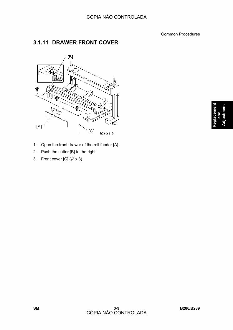
Common Procedures
SM 3-9 B286/B289
Rep
lace
men
t an
d A
djus
tmen
t
3.1.11 DRAWER FRONT COVER
1. Open the front drawer of the roll feeder [A].
2. Push the cutter [B] to the right.
3. Front cover [C] (" x 3)
CÓPIA NÃO CONTROLADA
CÓPIA NÃO CONTROLADA
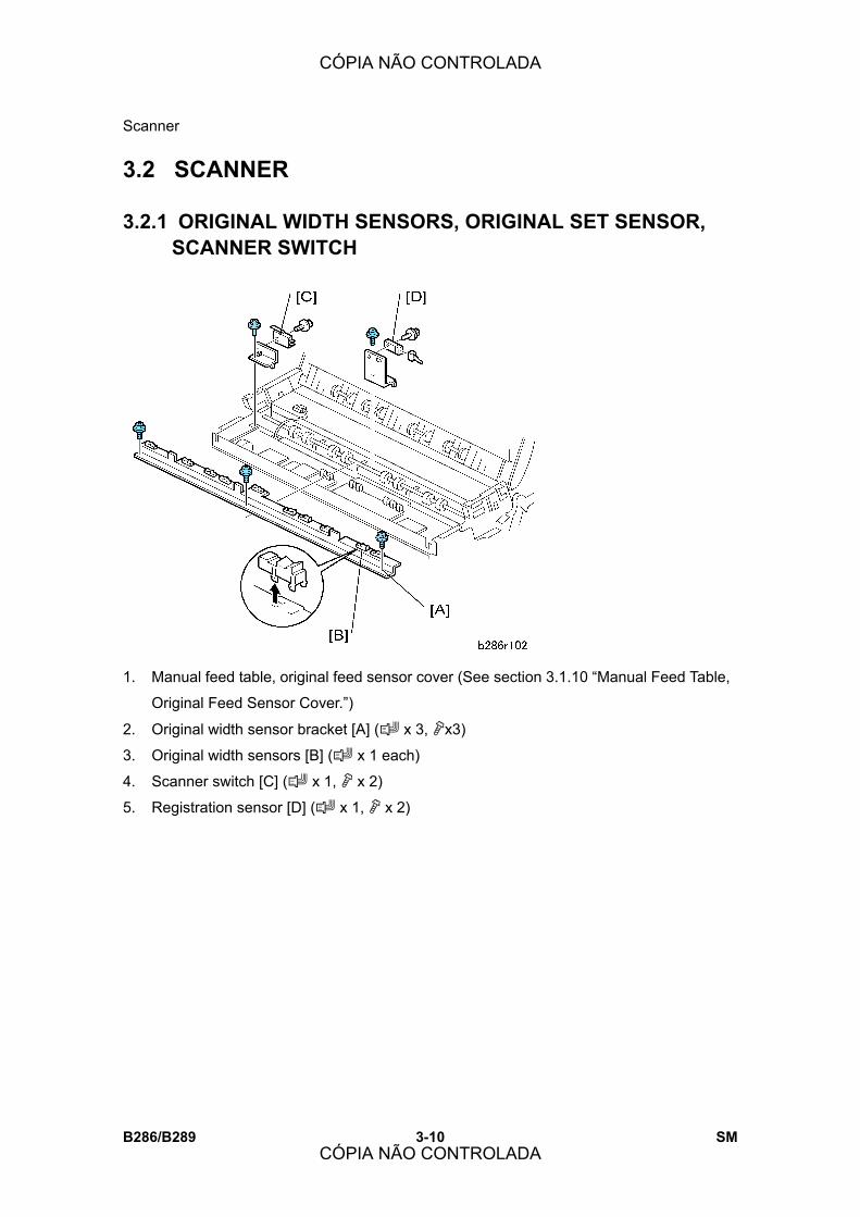
Scanner
B286/B289 3-10 SM
3.2 SCANNER
3.2.1 ORIGINAL WIDTH SENSORS, ORIGINAL SET SENSOR, SCANNER SWITCH
1. Manual feed table, original feed sensor cover (See section 3.1.10 �Manual Feed Table,
Original Feed Sensor Cover.�)
2. Original width sensor bracket [A] (# x 3, "x3)
3. Original width sensors [B] (# x 1 each)
4. Scanner switch [C] (# x 1, " x 2)
5. Registration sensor [D] (# x 1, " x 2)
CÓPIA NÃO CONTROLADA
CÓPIA NÃO CONTROLADA
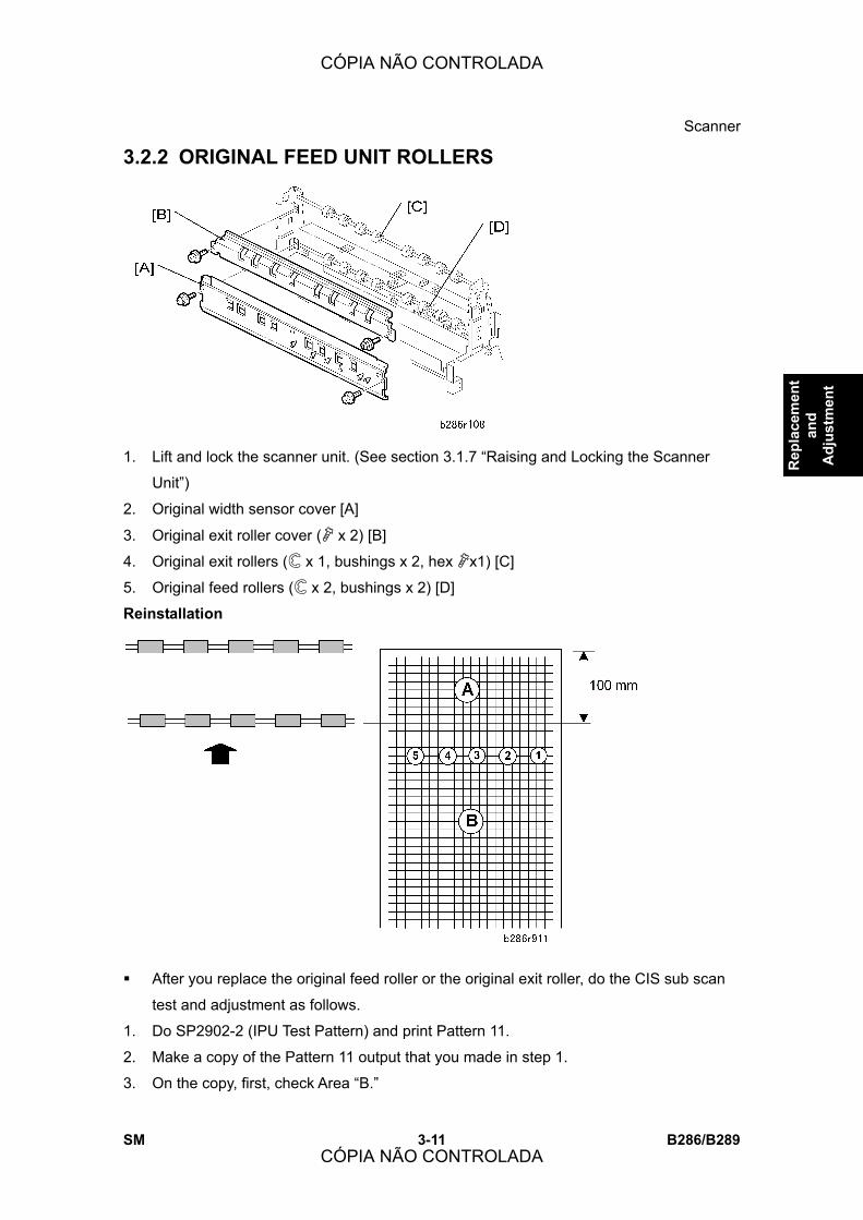
Scanner
SM 3-11 B286/B289
Rep
lace
men
t an
d A
djus
tmen
t
3.2.2 ORIGINAL FEED UNIT ROLLERS
1. Lift and lock the scanner unit. (See section 3.1.7 �Raising and Locking the Scanner
Unit�)
2. Original width sensor cover [A]
3. Original exit roller cover (" x 2) [B]
4. Original exit rollers ($ x 1, bushings x 2, hex "x1) [C]
5. Original feed rollers ($ x 2, bushings x 2) [D]
Reinstallation
! After you replace the original feed roller or the original exit roller, do the CIS sub scan
test and adjustment as follows.
1. Do SP2902-2 (IPU Test Pattern) and print Pattern 11.
2. Make a copy of the Pattern 11 output that you made in step 1.
3. On the copy, first, check Area �B.�
CÓPIA NÃO CONTROLADA
CÓPIA NÃO CONTROLADA

Scanner
B286/B289 3-12 SM
! If the lines at all the joints are correct (not broken), go to the next step. The joints
are labeled 1 to 5 in the diagram; these joints are at the same locations as the
joints between segments of the CIS.
! If the lines are broken at a joint, do SP4972 to adjust them. Then go to the next
step.
4. Next, check Area �A.�
! Area A (100 mm) is the distance that the original is fed by only the feed roller,
until the original exit roller gets and feeds the original.
! If the lines at the joints in Area A are correct (not broken), the procedure is
completed.
! If the lines are broken at a joint, do SP4965 to adjust them (adjust by trial and
error). Then go back to step 3 and check again.
3.2.3 EXPOSURE GLASS
1. Unlock and lift the original feed unit. (See section 3.1.6 �Removing the Original Feed
Unit.�)
2. Side covers (See Side Covers.)
3. Left exposure glass plate [A] (" x 1)
4. Right exposure glass plate [B] (" x 1)
5. Exposure glass [C]
! The exposure glass is very long and thin. It is very easy to break.
CÓPIA NÃO CONTROLADA
CÓPIA NÃO CONTROLADA
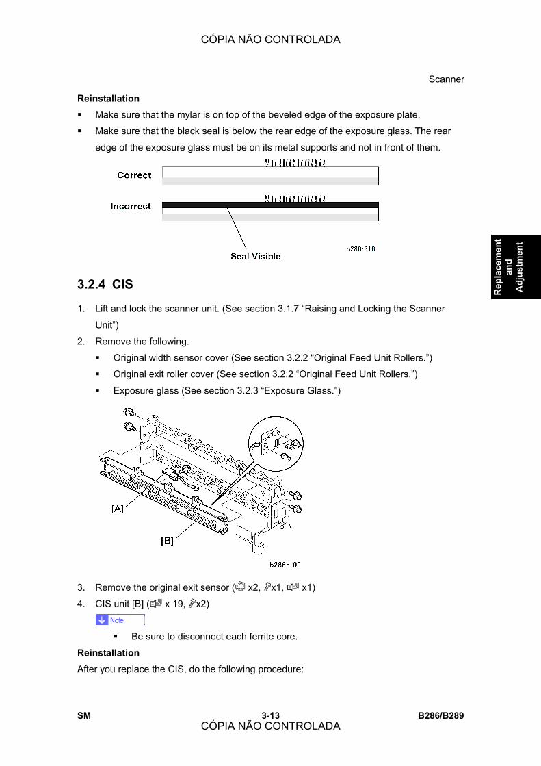
Scanner
SM 3-13 B286/B289
Rep
lace
men
t an
d A
djus
tmen
t
Reinstallation
! Make sure that the mylar is on top of the beveled edge of the exposure plate.
! Make sure that the black seal is below the rear edge of the exposure glass. The rear
edge of the exposure glass must be on its metal supports and not in front of them.
3.2.4 CIS
1. Lift and lock the scanner unit. (See section 3.1.7 �Raising and Locking the Scanner
Unit�)
2. Remove the following.
! Original width sensor cover (See section 3.2.2 �Original Feed Unit Rollers.�)
! Original exit roller cover (See section 3.2.2 �Original Feed Unit Rollers.�)
! Exposure glass (See section 3.2.3 �Exposure Glass.�)
3. Remove the original exit sensor (& x2, "x1, # x1)
4. CIS unit [B] (# x 19, "x2)
! Be sure to disconnect each ferrite core.
Reinstallation
After you replace the CIS, do the following procedure:
CÓPIA NÃO CONTROLADA
CÓPIA NÃO CONTROLADA
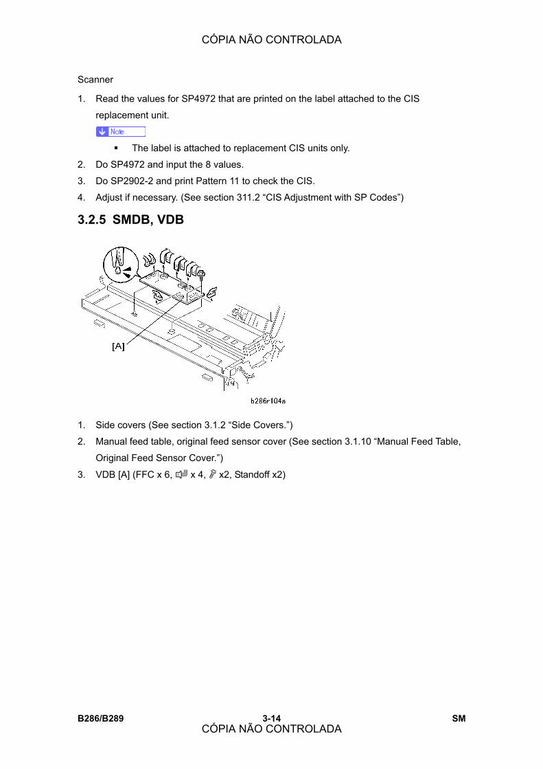
Scanner
B286/B289 3-14 SM
1. Read the values for SP4972 that are printed on the label attached to the CIS
replacement unit.
! The label is attached to replacement CIS units only.
2. Do SP4972 and input the 8 values.
3. Do SP2902-2 and print Pattern 11 to check the CIS.
4. Adjust if necessary. (See section 311.2 �CIS Adjustment with SP Codes�)
3.2.5 SMDB, VDB
1. Side covers (See section 3.1.2 �Side Covers.�)
2. Manual feed table, original feed sensor cover (See section 3.1.10 �Manual Feed Table,
Original Feed Sensor Cover.�)
3. VDB [A] (FFC x 6, # x 4, " x2, Standoff x2)
CÓPIA NÃO CONTROLADA
CÓPIA NÃO CONTROLADA

Scanner
SM 3-15 B286/B289
Rep
lace
men
t an
d A
djus
tmen
t
3.2.6 SIB, CGB POWER PACK
1. Side covers (See section 3.1.2 �Side Covers.�)
2. Remove (See section 3.1 �Common Procedures�):
! Manual feed table
! Original feed sensor cover
3. SIB [A] (#x9, "x4, Standoff x2)
4. CGB power pack [B] (# x 4, " x 2, standoffs x 2)
CÓPIA NÃO CONTROLADA
CÓPIA NÃO CONTROLADA
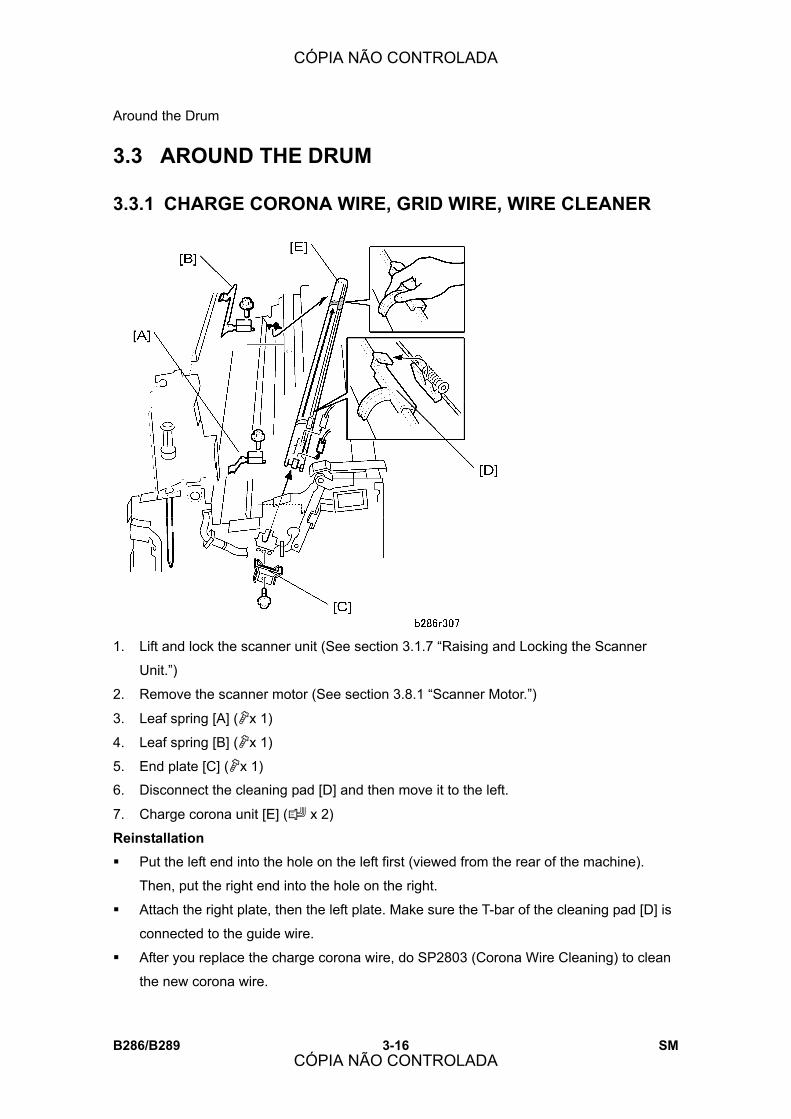
Around the Drum
B286/B289 3-16 SM
3.3 AROUND THE DRUM
3.3.1 CHARGE CORONA WIRE, GRID WIRE, WIRE CLEANER
1. Lift and lock the scanner unit (See section 3.1.7 �Raising and Locking the Scanner
Unit.�)
2. Remove the scanner motor (See section 3.8.1 �Scanner Motor.�)
3. Leaf spring [A] ("x 1)
4. Leaf spring [B] ("x 1)
5. End plate [C] ("x 1)
6. Disconnect the cleaning pad [D] and then move it to the left.
7. Charge corona unit [E] (# x 2)
Reinstallation
! Put the left end into the hole on the left first (viewed from the rear of the machine).
Then, put the right end into the hole on the right.
! Attach the right plate, then the left plate. Make sure the T-bar of the cleaning pad [D] is
connected to the guide wire.
! After you replace the charge corona wire, do SP2803 (Corona Wire Cleaning) to clean
the new corona wire.
CÓPIA NÃO CONTROLADA
CÓPIA NÃO CONTROLADA
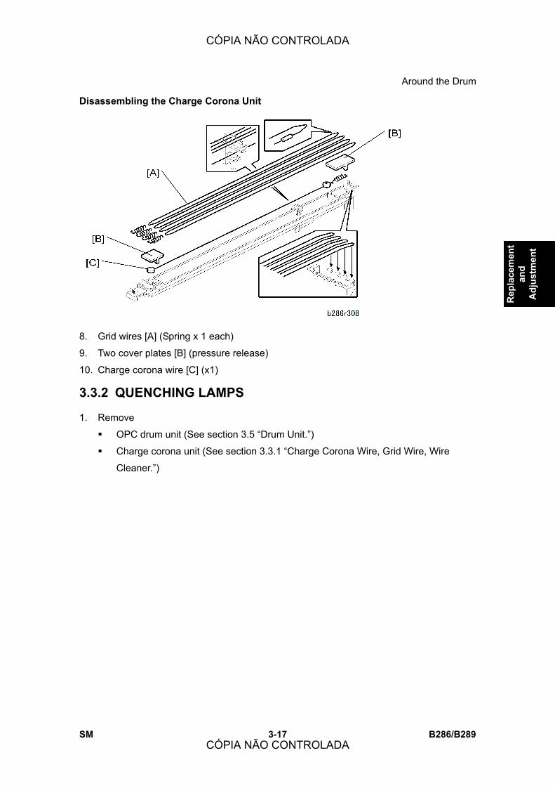
Around the Drum
SM 3-17 B286/B289
Rep
lace
men
t an
d A
djus
tmen
t
Disassembling the Charge Corona Unit
8. Grid wires [A] (Spring x 1 each)
9. Two cover plates [B] (pressure release)
10. Charge corona wire [C] (x1)
3.3.2 QUENCHING LAMPS
1. Remove
! OPC drum unit (See section 3.5 �Drum Unit.�)
! Charge corona unit (See section 3.3.1 �Charge Corona Wire, Grid Wire, Wire
Cleaner.�)
CÓPIA NÃO CONTROLADA
CÓPIA NÃO CONTROLADA
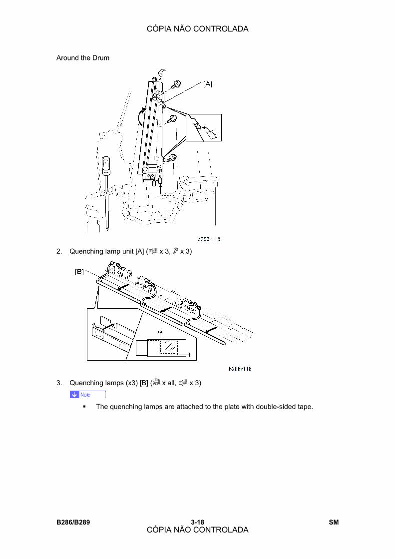
Around the Drum
B286/B289 3-18 SM
2. Quenching lamp unit [A] (# x 3, " x 3)
3. Quenching lamps (x3) [B] (& x all, # x 3)
! The quenching lamps are attached to the plate with double-sided tape.
CÓPIA NÃO CONTROLADA
CÓPIA NÃO CONTROLADA
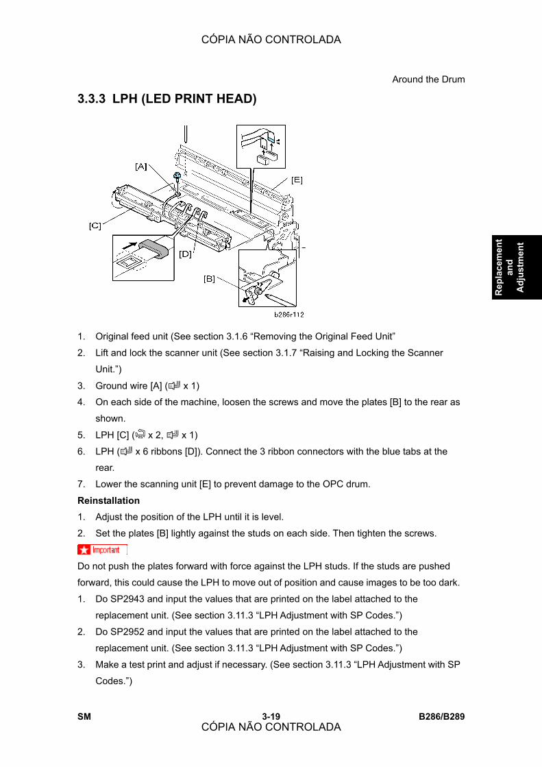
Around the Drum
SM 3-19 B286/B289
Rep
lace
men
t an
d A
djus
tmen
t
3.3.3 LPH (LED PRINT HEAD)
1. Original feed unit (See section 3.1.6 �Removing the Original Feed Unit�
2. Lift and lock the scanner unit (See section 3.1.7 �Raising and Locking the Scanner
Unit.�)
3. Ground wire [A] (# x 1)
4. On each side of the machine, loosen the screws and move the plates [B] to the rear as
shown.
5. LPH [C] (& x 2, # x 1)
6. LPH (# x 6 ribbons [D]). Connect the 3 ribbon connectors with the blue tabs at the
rear.
7. Lower the scanning unit [E] to prevent damage to the OPC drum.
Reinstallation
1. Adjust the position of the LPH until it is level.
2. Set the plates [B] lightly against the studs on each side. Then tighten the screws.
Do not push the plates forward with force against the LPH studs. If the studs are pushed
forward, this could cause the LPH to move out of position and cause images to be too dark.
1. Do SP2943 and input the values that are printed on the label attached to the
replacement unit. (See section 3.11.3 �LPH Adjustment with SP Codes.�)
2. Do SP2952 and input the values that are printed on the label attached to the
replacement unit. (See section 3.11.3 �LPH Adjustment with SP Codes.�)
3. Make a test print and adjust if necessary. (See section 3.11.3 �LPH Adjustment with SP
Codes.�)
CÓPIA NÃO CONTROLADA
CÓPIA NÃO CONTROLADA

Around the Drum
B286/B289 3-20 SM
3.3.4 TRANSFER CORONA, SEPARATION CORONA WIRES
1. Open the upper unit.
2. Side covers (See section 3.1.2 �Side Covers.�)
3. Transfer unit [A] (# x 2, " x 2)
Reinstallation
! At each end of the unit, make sure that the tabs [B] are fully engaged with the studs
[C].
! When the tabs are engaged correctly, the caps on the end are fully level.
Disassembling the Transfer Unit
1. Left cap [A] (tab release)
2. Right cap [B] (tab release)
CÓPIA NÃO CONTROLADA
CÓPIA NÃO CONTROLADA

Around the Drum
SM 3-21 B286/B289
Rep
lace
men
t an
d A
djus
tmen
t
! To remove a paper guide, lift it a small distance and move it in the direction of
the center. Make a note of the position of each guide. Each guide must be
installed at its original position.
3. Paper guides [C] (x4)
4. Transfer wire [D]
5. Separation wires [E]
Reinstallation
! Each paper guide pair must be installed at its original position.
! For each pair, the high guide is set on the outer side and the low guide is set on the
inner side.
! If each guide is not installed at its original position, this will cause paper to wrinkle.
CÓPIA NÃO CONTROLADA
CÓPIA NÃO CONTROLADA

Development
B286/B289 3-22 SM
3.4 DEVELOPMENT
3.4.1 DEVELOPMENT UNIT
1. Lift the upper unit.
2. Side covers (See section 3.1.2 �Side Covers�)
3. Manual feed table (See section 3.1.10 �Manual Feed Table, Original Feed Sensor
Cover�)
4. Toner hopper cover (See section 3.1.8 �Toner Hopper Cover�)
5. Idle registration roller panel (See section 3.1.9 �Idle Registration Roller Panel�)
6. Toner cartridge
7. Development unit [A] (# x 2, " x 6)
! The development unit is very heavy. Pull it out slowly.
Reinstallation
! Attach the large shoulder screws [B] on each side first, then attach the flat-head
screws [C].
CÓPIA NÃO CONTROLADA
CÓPIA NÃO CONTROLADA
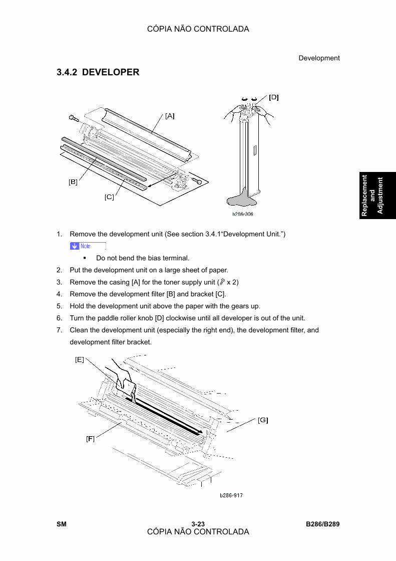
Development
SM 3-23 B286/B289
Rep
lace
men
t an
d A
djus
tmen
t
3.4.2 DEVELOPER
1. Remove the development unit (See section 3.4.1�Development Unit.�)
! Do not bend the bias terminal.
2. Put the development unit on a large sheet of paper.
3. Remove the casing [A] for the toner supply unit (" x 2)
4. Remove the development filter [B] and bracket [C].
5. Hold the development unit above the paper with the gears up.
6. Turn the paddle roller knob [D] clockwise until all developer is out of the unit.
7. Clean the development unit (especially the right end), the development filter, and
development filter bracket.
CÓPIA NÃO CONTROLADA
CÓPIA NÃO CONTROLADA
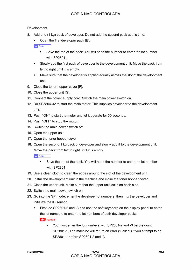
Development
B286/B289 3-24 SM
8. Add one (1 kg) pack of developer. Do not add the second pack at this time.
! Open the first developer pack [E].
! Save the top of the pack. You will need the number to enter the lot number
with SP2801.
! Slowly add the first pack of developer to the development unit. Move the pack from
left to right until it is empty.
! Make sure that the developer is applied equally across the slot of the development
unit.
9. Close the toner hopper cover [F].
10. Close the upper unit [G].
11. Connect the power supply cord. Switch the main power switch on.
12. Do SP5804-32 to start the main motor. This supplies developer to the development
unit.
13. Push �ON� to start the motor and let it operate for 30 seconds.
14. Push �OFF� to stop the motor.
15. Switch the main power switch off.
16. Open the upper unit.
17. Open the toner hopper cover.
18. Open the second 1 kg pack of developer and slowly add it to the development unit.
Move the pack from left to right until it is empty.
! Save the top of the pack. You will need the number to enter the lot number
with SP2801.
19. Use a clean cloth to clean the edges around the slot of the development unit.
20. Install the development unit in the machine and close the toner hopper cover.
21. Close the upper unit. Make sure that the upper unit locks on each side.
22. Switch the main power switch on.
23. Go into the SP mode, enter the developer lot numbers, then mix the developer and
initialize the ID sensor.
! First, do SP2801-2 and -3 and use the soft keyboard on the display panel to enter
the lot numbers to enter the lot numbers of both developer packs.
! You must enter the lot numbers with SP2801-2 and -3 before doing
SP2801-1. The machine will return an error (�Failed�) if you attempt to do
SP2801-1 before SP2801-2 and -3.
CÓPIA NÃO CONTROLADA
CÓPIA NÃO CONTROLADA

Development
SM 3-25 B286/B289
Rep
lace
men
t an
d A
djus
tmen
t
! If the lot numbers are the same, just enter the same number twice.
! Do SP2801-1 to mix the developer and initialize the ID sensor.
3.4.3 PAPER SET SENSOR, REGISTRATION SENSOR
1. Idle registration roller panel (See section 3.1.9 �Idle Registration Roller Panel.�)
2. Sensor bracket [A] (" x 1)
3. Paper set sensor [B] (# x 1)
4. Registration sensor [C] (# x 1)
CÓPIA NÃO CONTROLADA
CÓPIA NÃO CONTROLADA
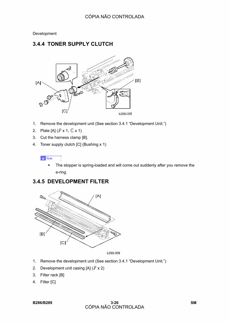
Development
B286/B289 3-26 SM
3.4.4 TONER SUPPLY CLUTCH
1. Remove the development unit (See section 3.4.1 �Development Unit.�)
2. Plate [A] (" x 1, $ x 1)
3. Cut the harness clamp [B].
4. Toner supply clutch [C] (Bushing x 1)
! The stopper is spring-loaded and will come out suddenly after you remove the
e-ring.
3.4.5 DEVELOPMENT FILTER
1. Remove the development unit (See section 3.4.1 �Development Unit.�)
2. Development unit casing [A] (" x 2)
3. Filter rack [B]
4. Filter [C]
CÓPIA NÃO CONTROLADA
CÓPIA NÃO CONTROLADA
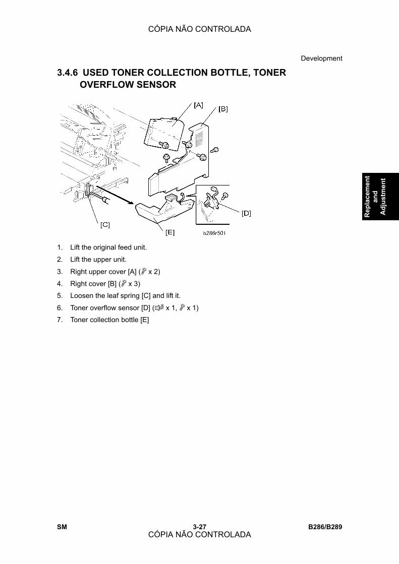
Development
SM 3-27 B286/B289
Rep
lace
men
t an
d A
djus
tmen
t
3.4.6 USED TONER COLLECTION BOTTLE, TONER OVERFLOW SENSOR
1. Lift the original feed unit.
2. Lift the upper unit.
3. Right upper cover [A] (" x 2)
4. Right cover [B] (" x 3)
5. Loosen the leaf spring [C] and lift it.
6. Toner overflow sensor [D] (# x 1, " x 1)
7. Toner collection bottle [E]
CÓPIA NÃO CONTROLADA
CÓPIA NÃO CONTROLADA
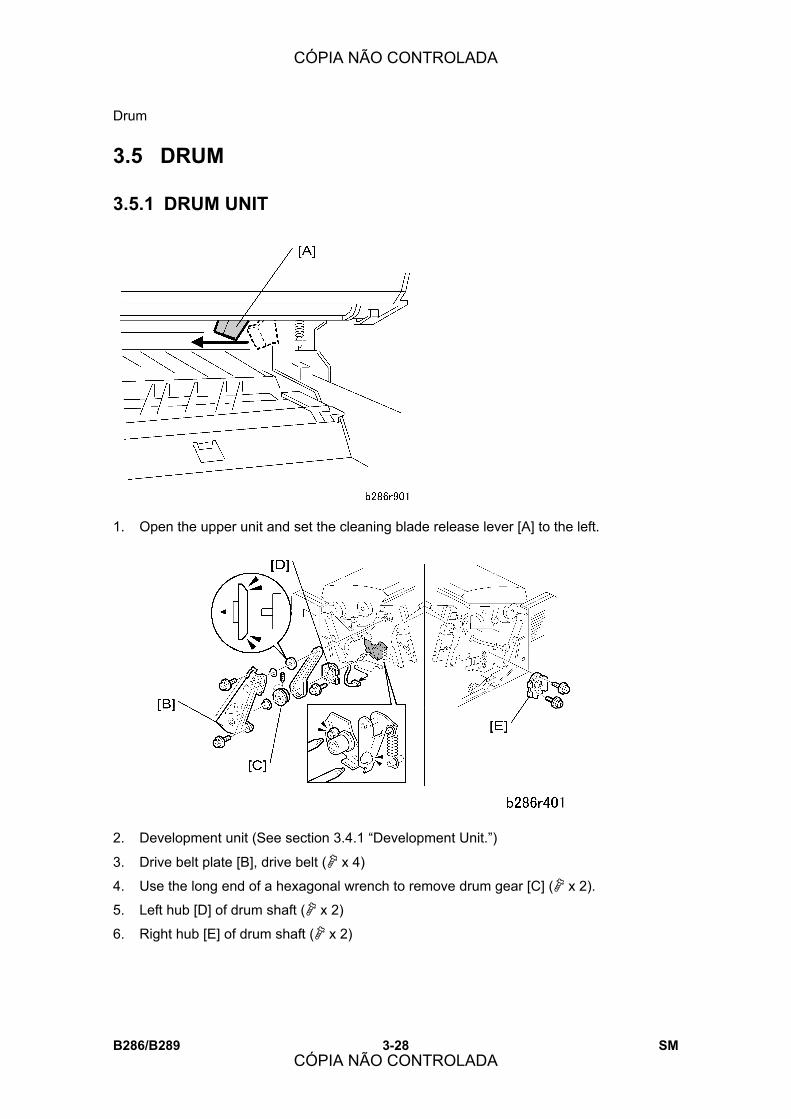
Drum
B286/B289 3-28 SM
3.5 DRUM
3.5.1 DRUM UNIT
1. Open the upper unit and set the cleaning blade release lever [A] to the left.
2. Development unit (See section 3.4.1 �Development Unit.�)
3. Drive belt plate [B], drive belt (" x 4)
4. Use the long end of a hexagonal wrench to remove drum gear [C] (" x 2).
5. Left hub [D] of drum shaft (" x 2)
6. Right hub [E] of drum shaft (" x 2)
CÓPIA NÃO CONTROLADA
CÓPIA NÃO CONTROLADA

Drum
SM 3-29 B286/B289
Rep
lace
men
t an
d A
djus
tmen
t
7. Drum unit [A]
! The drum unit is very heavy. Pull it out slowly.
! Do not touch the surface of the drum.
8. Drum [G] (" x 2. bushings x 2, plate x 1)
Reinstallation
After you replace the drum:
! Do SP2923 (Cleaning Blade Replace Mode). This applies toner to the drum and blade
to decrease friction between the drum and the cleaning blade. If you do this, scratches
on the drum or a bent cleaning blade are less possible to occur.
! Do SP3001-2 to initialize the ID sensor.
! Be sure to tighten the hexagonal lock screws in the drum gear.
CÓPIA NÃO CONTROLADA
CÓPIA NÃO CONTROLADA

Drum
B286/B289 3-30 SM
! Set the cleaning-blade release lever to the right.
3.5.2 CLEANING BLADE
1. Cleaning blade [A] (" x 2, springs x 2)
Reinstallation
After you replace the cleaning blade:
! Do SP2923 (Cleaning Blade Replace Mode). This applies toner to the drum and blade
to decrease friction between the drum and the cleaning blade. If you do this, scratches
on the drum or a bent cleaning blade are less possible to occur.
CÓPIA NÃO CONTROLADA
CÓPIA NÃO CONTROLADA

Drum
SM 3-31 B286/B289
Rep
lace
men
t an
d A
djus
tmen
t
3.5.3 ID SENSOR, PICK-OFF PAWLS, PICK-OFF PAWL SOLENOID
1. Drum (See section 3.5.1 �Drum Unit.�)
2. Cleaning blade (See section 3.5.2 �Cleaning Blade�)
3. ID sensor [A] (& x 3, # x 1, " x 1)
4. Pick-off pawls (x2) [B] (pressure release).
5. Pick-off pawl solenoid [C] (# x 2, " x 1)
Reinstallation
! After replacing or cleaning the ID sensor, do SP3001-2 to initialize the new ID sensor.
! If the ID sensor is damaged and cannot be replaced immediately, set SP2208-3 (Toner
Supply Setting � Toner Supply Mode) to �1.� Then the customer can continue to use
the machine until a new ID sensor is available. After you install a new ID sensor, reset
this SP to 0.
CÓPIA NÃO CONTROLADA
CÓPIA NÃO CONTROLADA

Paper Feed
B286/B289 3-32 SM
3.6 PAPER FEED
3.6.1 REGISTRATION CLUTCH, REGISTRATION ROLLER
1. Side covers (See section 3.1.2 �Side Covers.�)
2. Registration clutch [A] (& x 1, # x 1)
3. Gear cover plate [B] (" x 7, cap x 1, drive belt x 1)
4. Gear [C] ($ x 1, spring x 1)
5. Gear [D] ($ x 1)
6. Used toner collection bottle (See section 3.4.6 �Used Toner Collection Bottle, Toner
Overflow Sensor�)
CÓPIA NÃO CONTROLADA
CÓPIA NÃO CONTROLADA

Paper Feed
SM 3-33 B286/B289
Rep
lace
men
t an
d A
djus
tmen
t
7. Cover plate [E] (" x 5)
8. Switch pressure plate [F]
! At reinstallation, make sure that the vertical brace [G] is locked in the cutouts
in the ceramic clutch [H] (see illustration above).
9. Front plate [I] (" x 6)
10. Transport roller dust cover [J] (" x 4)
11. Registration roller [K] ($ x 2, bushings x 2, torque limiter x 1, " x1)
CÓPIA NÃO CONTROLADA
CÓPIA NÃO CONTROLADA

Paper Feed
B286/B289 3-34 SM
3.6.2 ROLL 1 PAPER FEED CLUTCH, FEED ROLLER
1. Open the roll feeder drawer.
2. Remove the paper rolls.
3. Roll 1 feed clutch cover [A] (" x 2)
4. Roll 1 feed clutch [B] (# x 1, $ x 1)
5. Roll 1 feed rollers [C] ($ x 3, bushings x 2)
6. After you replace the roller or the clutch, adjust the cut length with SP1920-111 and SP
1920-115. (See section 3.11.1 �Image Adjustment with SP Codes.�)
CÓPIA NÃO CONTROLADA
CÓPIA NÃO CONTROLADA

Paper Feed
SM 3-35 B286/B289
Rep
lace
men
t an
d A
djus
tmen
t
3.6.3 ROLL 2 PAPER CLUTCH, FEED ROLLER
! The procedure is for the B642 only.
1. Open the roll feeder drawer.
2. Remove paper roll 2 (at the rear).
3. Roll 2 feed clutch cover [A] (" x 2)
4. Roll 2 feed clutch [B] (# x 1, $ x 1)
5. Roll 2 feed rollers [C] ($ x3, bushings x 2)
6. After you replace the roller or the clutch, adjust the cut length with SP 1920-211 and
SP 1920-215. (See section 3.11.1 �Image Adjustment with SP Codes.�)
CÓPIA NÃO CONTROLADA
CÓPIA NÃO CONTROLADA
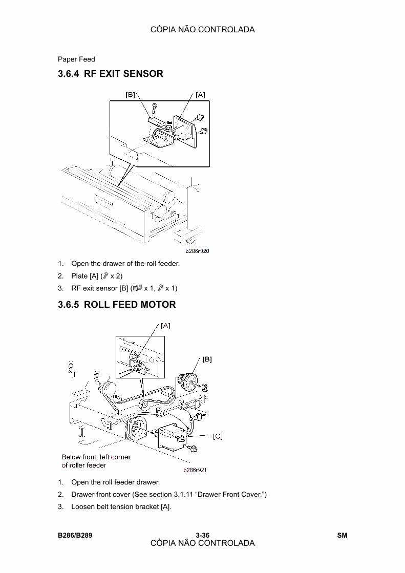
Paper Feed
B286/B289 3-36 SM
3.6.4 RF EXIT SENSOR
1. Open the drawer of the roll feeder.
2. Plate [A] (" x 2)
3. RF exit sensor [B] (# x 1, " x 1)
3.6.5 ROLL FEED MOTOR
1. Open the roll feeder drawer.
2. Drawer front cover (See section 3.1.11 �Drawer Front Cover.�)
3. Loosen belt tension bracket [A].
CÓPIA NÃO CONTROLADA
CÓPIA NÃO CONTROLADA

Paper Feed
SM 3-37 B286/B289
Rep
lace
men
t an
d A
djus
tmen
t
4. Gear [B] (% x1)
5. Roll feeder motor [C] (& x 2, # x 1, " x 2)
3.6.6 CUTTER MOTOR, HP SENSORS
1. Open the roller feeder drawer.
2. Drawer front cover (See section 3.1.11 �Drawer Front Cover�)
3. Upper bracket [A] (" x 2)
4. Lower bracket [B] (spring x 1, " x 1, $ x 1)
CÓPIA NÃO CONTROLADA
CÓPIA NÃO CONTROLADA

Paper Feed
B286/B289 3-38 SM
5. Right cutter HP switch [C] (& x 1, # x 1)
6. Left cutter HP switch [D] (& x 1, # x 1)
7. Cutter, race, and motor assembly [E] (& x 3, # x 1, " x 2)
8. Cutter motor [F] (" x 2)
3.6.7 ROLL PAPER END SENSORS
1. Open the roll feeder drawer.
2. Roll feeder back plate [A] ("x 2)
3. Roll end sensors [B] (# x 1, " x 1 each)
! The Roll Feeder B641 has one roll end sensor, and the Roll Feeder B642 has two
roll end sensors.
CÓPIA NÃO CONTROLADA
CÓPIA NÃO CONTROLADA

Paper Feed
SM 3-39 B286/B289
Rep
lace
men
t an
d A
djus
tmen
t
3.6.8 CASSETTE FEED ROLLER
1. Paper cassette [A]
2. Cassette feed roller [B]
3.6.9 CASSETTE RELAY SENSOR, CASSETTE END SENSOR
1. Open the roll feeder drawer and remove the paper cassette.
2. Roll feeder rear plate (" x 2 Blue)
3. RFDB shield plate [A] (" x 2 Blue).
4. Paper cassette unit [B] (& x 6, # x 2, " x 4 Blue)
CÓPIA NÃO CONTROLADA
CÓPIA NÃO CONTROLADA

Paper Feed
B286/B289 3-40 SM
! Pull the unit to the rear, then remove it from the front.
5. Relay sensor plate [C] (" x 1 Blue)
6. Relay sensor [D] (# x 1, pinch release x 2)
7. Cassette end sensor plate [E] (" x 1 Blue)
8. Cassette end sensor [F] (# x 1, " x 1, pinch release x 3)
3.6.10 CASSETTE FEED MOTOR, CASSETTE OPEN SENSOR
1. Open the roll feeder drawer and remove the paper cassette unit.
2. Relay sensor plate, cassette end sensor plate [A] (" x 1 each)
CÓPIA NÃO CONTROLADA
CÓPIA NÃO CONTROLADA

Paper Feed
SM 3-41 B286/B289
Rep
lace
men
t an
d A
djus
tmen
t
3. Cassette open sensor [B] (# x 1, pinch release x 2)
4. Paper cassette feed assembly [C] (" x 6)
5. Paper cassette motor [D] (& x 2, # x 1, " x 2)
3.6.11 CASSETTE FEED CLUTCH
1. Cassette feed motor (See section 3.6.10 �Cassette Feed Motor, Cassette Open
Sensor�)
2. Motor mount plate [A] ("x 2)
3. Cassette feed clutch [B] (& x 1, # x 1)
CÓPIA NÃO CONTROLADA
CÓPIA NÃO CONTROLADA
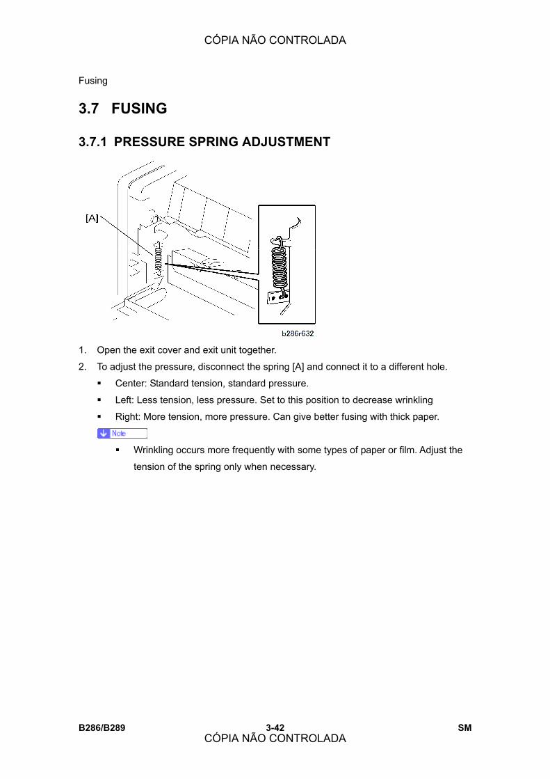
Fusing
B286/B289 3-42 SM
3.7 FUSING
3.7.1 PRESSURE SPRING ADJUSTMENT
1. Open the exit cover and exit unit together.
2. To adjust the pressure, disconnect the spring [A] and connect it to a different hole.
! Center: Standard tension, standard pressure.
! Left: Less tension, less pressure. Set to this position to decrease wrinkling
! Right: More tension, more pressure. Can give better fusing with thick paper.
! Wrinkling occurs more frequently with some types of paper or film. Adjust the
tension of the spring only when necessary.
CÓPIA NÃO CONTROLADA
CÓPIA NÃO CONTROLADA
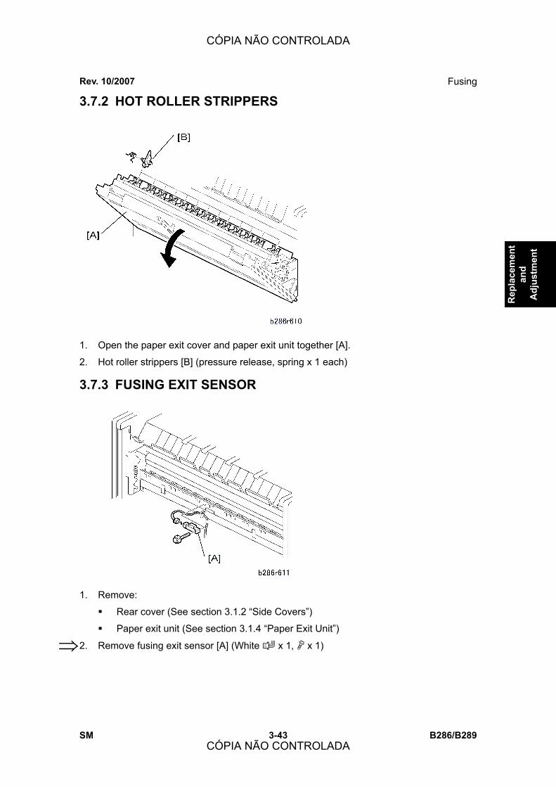
Fusing
SM 3-43 B286/B289
Rep
lace
men
t an
d A
djus
tmen
t
3.7.2 HOT ROLLER STRIPPERS
1. Open the paper exit cover and paper exit unit together [A].
2. Hot roller strippers [B] (pressure release, spring x 1 each)
3.7.3 FUSING EXIT SENSOR
1. Remove:
Rear cover (See section 3.1.2 “Side Covers”)
Paper exit unit (See section 3.1.4 “Paper Exit Unit”)
2. Remove fusing exit sensor [A] (White x 1, x 1) ⇒
Rev. 10/2007
CÓPIA NÃO CONTROLADA
CÓPIA NÃO CONTROLADA

Fusing
B286/B289 3-44 SM
3.7.4 PRESSURE ROLLER THERMISTORS
1. Remove:
! Rear cover (See section 3.1.3 �Rear Cover�)
! Paper exit unit (See section 3.1.4 �Paper Exit Unit�)
2. Remove pressure roller thermistors [A] (# x 1, " x 2, &x1).
! The end roller thermistor is at .
! The center roller thermistor is at .
! You must first remove the stripper unit [B] in order to remove the center
thermistor .
CÓPIA NÃO CONTROLADA
CÓPIA NÃO CONTROLADA

Fusing
SM 3-45 B286/B289
Rep
lace
men
t an
d A
djus
tmen
t
3.7.5 PRESSURE ROLLER STRIPPERS
1. Remove:
! Rear cover (" x 2). See section 3.1.3 �Rear Cover�
! Paper exit unit and exit cover (" x 4, # x 1) See section 3.1.4 �Paper Exit Unit�
2. Remove:
! Pressure roller stripper unit [A] (" x 4)
! Stopper screw [B] (" x 1 ea.)
! Pressure roller strippers [C] (Spring x 1 each)
! There are 11 pressure roller strippers. To remove them, push back and pull
out.
3.7.6 EXIT UNIT SWITCH
1. Remove the pressure roller stripper unit [A]. (See section 3.7.5 �Pressure Roller
Strippers�).
CÓPIA NÃO CONTROLADA
CÓPIA NÃO CONTROLADA

Fusing
B286/B289 3-46 SM
2. Remove the exit unit switch [B].
! Use tips of two small flat-head screwdrivers to release the tabs at the top and
bottom of the switch to release it, then pull it out.
3.7.7 FUSING UNIT
! Switch the main power switch off. Then disconnect the machine from its power
source. Let the fusing unit become cool for 10 minutes or more before you remove
it.
1. Open the upper unit.
2. Paper exit unit (See section 3.1.4 �Paper Exit Unit.�)
3. Pressure roller thermistor, fusing exit sensor (See section 3.7.4 �Pressure Roller
Thermistors.�)
4. Fusing Exit Sensor (See section 3.7.3 �Fusing Exit Sensor�)
5. Braces (x 3) [A] (" x 2 each)
! Install the brace with attached harness clamp in the center.
6. Fusing unit [B] (# x 2, " x 2)
7. Push down the levers [C] when you remove the fusing unit.
! The fusing unit is heavy. Pull it out slowly.
Reinstallation
! Make sure that the upper unit is open when you install the fusing unit.
! Push down on the levers [C] while you set the fusing unit in the machine.
CÓPIA NÃO CONTROLADA
CÓPIA NÃO CONTROLADA

Fusing
SM 3-47 B286/B289
Rep
lace
men
t an
d A
djus
tmen
t
! Connect the color coded connectors correctly:
Europe: Blue - Blue, White - White
North America: Red - Red, White - White
3.7.8 FUSING CLEANING ROLLER
1. Fusing unit (See section 3.7.7 �Fusing Unit�)
2. Springs [A] (x 2)
3. Felt plate [B] (" x 2)
4. Fusing cleaning roller [C] (" x 2, bushings x 2)
! The brown bushing is on the right; the white bushing is on the left.
CÓPIA NÃO CONTROLADA
CÓPIA NÃO CONTROLADA
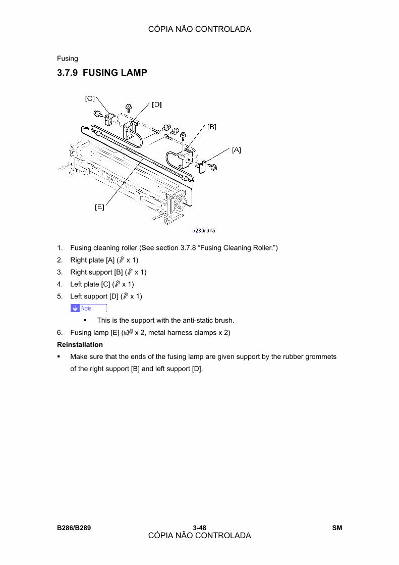
Fusing
B286/B289 3-48 SM
3.7.9 FUSING LAMP
1. Fusing cleaning roller (See section 3.7.8 �Fusing Cleaning Roller.�)
2. Right plate [A] (" x 1)
3. Right support [B] (" x 1)
4. Left plate [C] (" x 1)
5. Left support [D] (" x 1)
! This is the support with the anti-static brush.
6. Fusing lamp [E] (# x 2, metal harness clamps x 2)
Reinstallation
! Make sure that the ends of the fusing lamp are given support by the rubber grommets
of the right support [B] and left support [D].
CÓPIA NÃO CONTROLADA
CÓPIA NÃO CONTROLADA
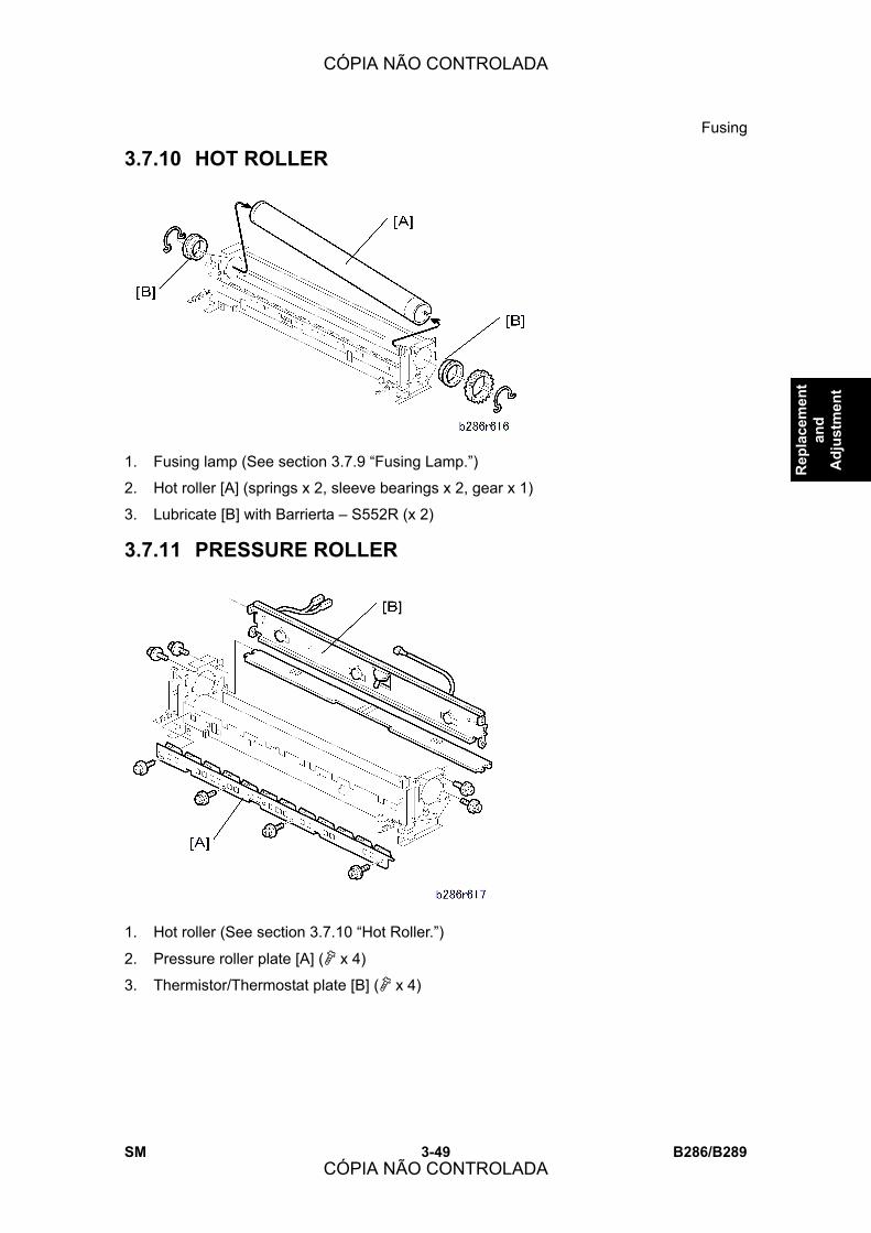
Fusing
SM 3-49 B286/B289
Rep
lace
men
t an
d A
djus
tmen
t
3.7.10 HOT ROLLER
1. Fusing lamp (See section 3.7.9 �Fusing Lamp.�)
2. Hot roller [A] (springs x 2, sleeve bearings x 2, gear x 1)
3. Lubricate [B] with Barrierta � S552R (x 2)
3.7.11 PRESSURE ROLLER
1. Hot roller (See section 3.7.10 �Hot Roller.�)
2. Pressure roller plate [A] (" x 4)
3. Thermistor/Thermostat plate [B] (" x 4)
CÓPIA NÃO CONTROLADA
CÓPIA NÃO CONTROLADA

Fusing
B286/B289 3-50 SM
4. Pressure roller [C] (sleeve bearings x 2)
3.7.12 HOT ROLLER THERMISTOR, THERMOSTATS
1. Fusing unit (See section 3.7.7 �Fusing Unit.�)
2. Hot roller thermistor [A] (x1) (" x 1)
3. Thermostat 2 � 199 °C [B] (" M3x6 x 2)
4. Thermostat 1 � 200 °C [C] (" M3x6 x 2)
Reinstallation
! The thermostats (199 °C and 200 °C) must be installed at [B] and [C]. �199� and �200�
are clearly shown on the edge of each thermostat.
CÓPIA NÃO CONTROLADA
CÓPIA NÃO CONTROLADA
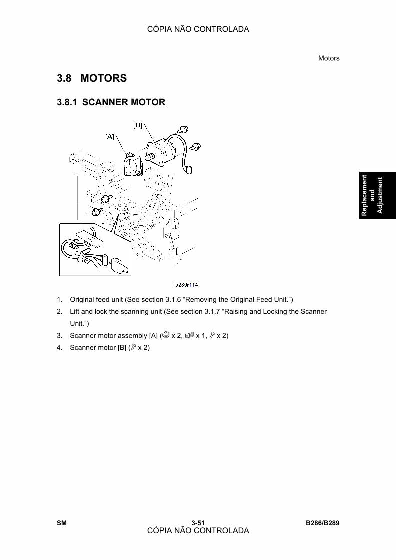
Motors
SM 3-51 B286/B289
Rep
lace
men
t an
d A
djus
tmen
t
3.8 MOTORS
3.8.1 SCANNER MOTOR
1. Original feed unit (See section 3.1.6 �Removing the Original Feed Unit.�)
2. Lift and lock the scanning unit (See section 3.1.7 �Raising and Locking the Scanner
Unit.�)
3. Scanner motor assembly [A] (& x 2, # x 1, " x 2)
4. Scanner motor [B] (" x 2)
CÓPIA NÃO CONTROLADA
CÓPIA NÃO CONTROLADA

Motors
B286/B289 3-52 SM
3.8.2 DRUM MOTOR
1. Original feed unit (See section 3.1.6 �Removing the Original Feed Unit.�)
2. Lift and lock the scanning unit (See section 3.1.7 �Raising and Locking the Scanner
Unit.�)
3. Cover [A] ("x4)
4. Belt tension plate [B] (" x 2, Spring x 1)
5. Drum motor [C] (# x 1, " x 3)
3.8.3 FUSING MOTOR, MAIN MOTOR
1. Open the upper unit.
2. Side covers (See section 3.1.2 �Side Covers.�)
3. Registration clutch [A] (& x 1, # x 1)
CÓPIA NÃO CONTROLADA
CÓPIA NÃO CONTROLADA
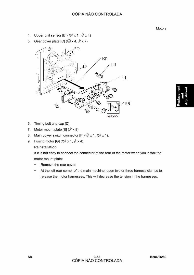
Motors
SM 3-53 B286/B289
Rep
lace
men
t an
d A
djus
tmen
t
4. Upper unit sensor [B] (# x 1, & x 4)
5. Gear cover plate [C] (& x 4, " x 7)
6. Timing belt and cap [D]
7. Motor mount plate [E] (" x 8)
8. Main power switch connector [F] (& x 1, # x 1).
9. Fusing motor [G] (# x 1, " x 4)
Reinstallation
If it is not easy to connect the connector at the rear of the motor when you install the
motor mount plate:
! Remove the rear cover.
! At the left rear corner of the main machine, open two or three harness clamps to
release the motor harnesses. This will decrease the tension in the harnesses.
CÓPIA NÃO CONTROLADA
CÓPIA NÃO CONTROLADA

Motors
B286/B289 3-54 SM
10. Remove the gear cover plate and motor mount plate. (Please refer to the two pages
before this one.)
11. Main motor [H] (# x 2, drive belts x 2, " x 4)
3.8.4 USED TONER BOTTLE MOTOR
1. PSU (See section 3.9.1 �PSU/Circuit Breaker.�)
2. Toner collection bottle (See section 3.4.6 �Used Toner Collection Bottle, Toner
Overflow Sensor.�)
3. T&S power pack (See section 3.9.5 �T&S Power Pack.�)
4. Motor plate [A] (& x 1, # x 1, " x 2)
5. Motor [B] (" x 2)
CÓPIA NÃO CONTROLADA
CÓPIA NÃO CONTROLADA
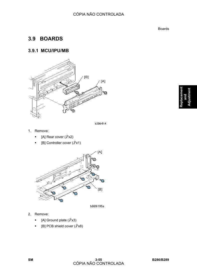
Boards
SM 3-55 B286/B289
Rep
lace
men
t an
d A
djus
tmen
t
3.9 BOARDS
3.9.1 MCU/IPU/MB
1. Remove:
! [A] Rear cover ("x2)
! [B] Controller cover ("x1)
2. Remove:
! [A] Ground plate ("x3)
! [B] PCB shield cover ("x8)
CÓPIA NÃO CONTROLADA
CÓPIA NÃO CONTROLADA

Boards
B286/B289 3-56 SM
3. If there are any optional boards installed on the controller Unit [A], remove them before
removing the controller board ("x2 each).
! Always remove the File Format Converter under the controller board, before
pulling the controller board out of the machine.
4. Remove the file format converter board.
! [1] Connectors (#x3)
! [2] File format converter board ("x2).
! Slide the board out slowly to avoid snagging the board on any connector
harnesses below the board.
5. Remove the controller unit ("x7).
CÓPIA NÃO CONTROLADA
CÓPIA NÃO CONTROLADA

Boards
SM 3-57 B286/B289
Rep
lace
men
t an
d A
djus
tmen
t
6. Disconnect the IPU and MCU harnesses , , (&x7, #x all).
7. Disconnect the MCU/IPU bracket.
! [A] MCU side ("x2, #x1)
! [B] IPU side ("x2, #x2)
8. Pull the controller housing out of the machine.
CÓPIA NÃO CONTROLADA
CÓPIA NÃO CONTROLADA
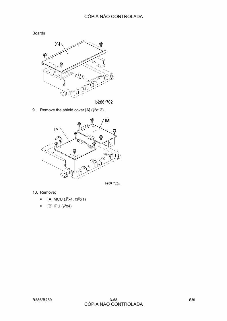
Boards
B286/B289 3-58 SM
9. Remove the shield cover [A] ("x12).
10. Remove:
! [A] MCU ("x4, #x1)
! [B] IPU ("x4)
CÓPIA NÃO CONTROLADA
CÓPIA NÃO CONTROLADA
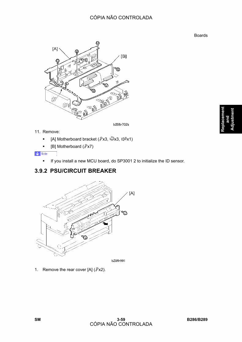
Boards
SM 3-59 B286/B289
Rep
lace
men
t an
d A
djus
tmen
t
11. Remove:
! [A] Motherboard bracket ("x3, &x3, #x1)
! [B] Motherboard ("x7)
! If you install a new MCU board, do SP3001 2 to initialize the ID sensor.
3.9.2 PSU/CIRCUIT BREAKER
1. Remove the rear cover [A] ("x2).
CÓPIA NÃO CONTROLADA
CÓPIA NÃO CONTROLADA

Boards
B286/B289 3-60 SM
2. Remove:
! [A] Earth plate ("x2)
! [B] Earth plate ("x2)
3. Disconnect the white and black harnesses [C] (#x2).
4. Remove the circuit breaker [D] ("x2, #x4).
5. Remove the PSU [A] ("x1, #x10, &x all)
CÓPIA NÃO CONTROLADA
CÓPIA NÃO CONTROLADA

Boards
SM 3-61 B286/B289
Rep
lace
men
t an
d A
djus
tmen
t
3.9.3 CONTROLLER BOARD
1. Remove:
! [A] Rear cover ("x2)
! [B] Controller cover ("x1)
2. Remove:
! [A] Ground plate ("x3)
! [B] PCB shield cover ("x8)
CÓPIA NÃO CONTROLADA
CÓPIA NÃO CONTROLADA
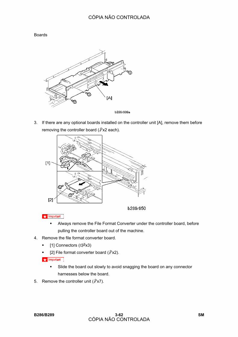
Boards
B286/B289 3-62 SM
3. If there are any optional boards installed on the controller unit [A], remove them before
removing the controller board ("x2 each).
! Always remove the File Format Converter under the controller board, before
pulling the controller board out of the machine.
4. Remove the file format converter board.
! [1] Connectors (#x3)
! [2] File format converter board ("x2).
! Slide the board out slowly to avoid snagging the board on any connector
harnesses below the board.
5. Remove the controller unit ("x7).
CÓPIA NÃO CONTROLADA
CÓPIA NÃO CONTROLADA

Boards
SM 3-63 B286/B289
Rep
lace
men
t an
d A
djus
tmen
t
6. Remove the controller board [A] ("x7, #x3).
! [A] Memory chips
! [B] NVRAM (if you change the controller board, put the old NVRAM on the new
board)
! [C] Rails
! [D] SD card (if installed)
CÓPIA NÃO CONTROLADA
CÓPIA NÃO CONTROLADA

Boards
B286/B289 3-64 SM
3.9.4 NVRAM
1. Remove the controller board (See section 3.9.3 �Controller Board�)
2. Remove the NVRAM [A]
NVRAM Upload Do this procedure to upload the NVRAM data from NVRAM to an SD card. Do this
procedure before replacing the NVRAM.
1. Switch the machine off.
2. Insert an SD card in SD card Slot 3.
3. Switch the machine on.
4. Go into the SP mode and do SP5824 (Upload NVRAM Data).
5. When you see �Completed!�, switch the machine off.
NVRAM Download Do this procedure to download the NVRAM data from an SD card to the NVRAM in the
machine.
1. Switch the main power switch off.
2. If a new NVRAM is to be installed, do SP5801-2 to make sure that the new NVRAM is
clear.
! After clearing the NVRAM, confirm that the total counter has been reset to 0:
[User Tools]> [Counter].
3. Do SP5811 (Machine Serial Number) to set the serial number.
4. Insert the SD card with the NVRAM data in SD card Slot 3.
5. Switch the main power switch on.
6. Go into SP mode and do SP5825 (Download NVRAM Data).
CÓPIA NÃO CONTROLADA
CÓPIA NÃO CONTROLADA

Boards
SM 3-65 B286/B289
Rep
lace
men
t an
d A
djus
tmen
t
7. Follow the instructions on the operating panel display to execute the download.
8. Switch the main power switch off.
9. Switch the main power switch on.
10. If the Data Overwrite Security Unit Type D (B735-18) has been installed, it must be
installed again.
11. Do SP3001 2 to initialize the ID sensor.
3.9.5 T&S POWER PACK
Remove:
! PSU (See section 3.9.2 �PSU/Circuit Breaker�)
! [A] T&S power pack mounting plate (& x 2, # x 3, " x 1)
! [B] T&S power pack (" x 1)
CÓPIA NÃO CONTROLADA
CÓPIA NÃO CONTROLADA
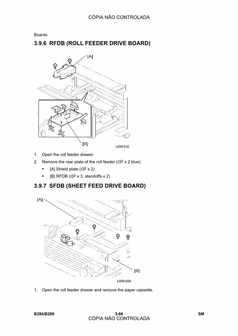
Boards
B286/B289 3-66 SM
3.9.6 RFDB (ROLL FEEDER DRIVE BOARD)
1. Open the roll feeder drawer.
2. Remove the rear plate of the roll feeder (# x 2 blue)
! [A] Shield plate (# x 2)
! [B] RFDB (# x 3, standoffs x 2)
3.9.7 SFDB (SHEET FEED DRIVE BOARD)
1. Open the roll feeder drawer and remove the paper cassette.
CÓPIA NÃO CONTROLADA
CÓPIA NÃO CONTROLADA

Boards
SM 3-67 B286/B289
Rep
lace
men
t an
d A
djus
tmen
t
2. Remove Roll feeder rear plate (" x 2 Blue) (See section 3.6.7 �Roll Paper End
Sensors�)
[A] RFDB shield plate [A] (" x 2).
[B] Paper cassette unit [B] (&x 4, # x 2, " x 4)
! Pull the unit to the rear, remove it from the front.
3. Remove the SFDB [A] (# x 2, " x 2, standoffs x 2)
CÓPIA NÃO CONTROLADA
CÓPIA NÃO CONTROLADA
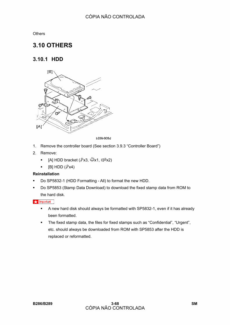
Others
B286/B289 3-68 SM
3.10 OTHERS
3.10.1 HDD
1. Remove the controller board (See section 3.9.3 �Controller Board�)
2. Remove:
! [A] HDD bracket ("x3, &x1, #x2)
! [B] HDD ("x4)
Reinstallation
! Do SP5832-1 (HDD Formatting - All) to format the new HDD.
! Do SP5853 (Stamp Data Download) to download the fixed stamp data from ROM to
the hard disk.
! A new hard disk should always be formatted with SP5832-1, even if it has already
been formatted.
! The fixed stamp data, the files for fixed stamps such as �Confidential�, �Urgent�,
etc. should always be downloaded from ROM with SP5853 after the HDD is
replaced or reformatted.
CÓPIA NÃO CONTROLADA
CÓPIA NÃO CONTROLADA
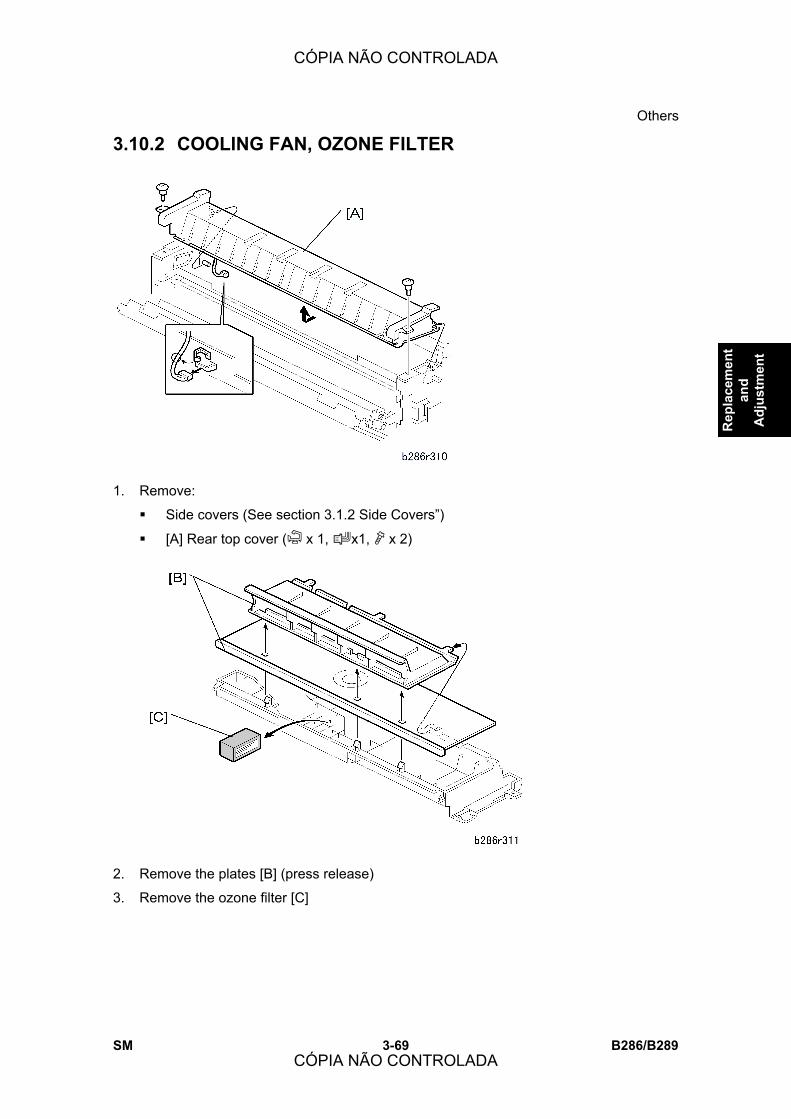
Others
SM 3-69 B286/B289
Rep
lace
men
t an
d A
djus
tmen
t
3.10.2 COOLING FAN, OZONE FILTER
1. Remove:
! Side covers (See section 3.1.2 Side Covers�)
! [A] Rear top cover (& x 1, #x1, " x 2)
2. Remove the plates [B] (press release)
3. Remove the ozone filter [C]
CÓPIA NÃO CONTROLADA
CÓPIA NÃO CONTROLADA
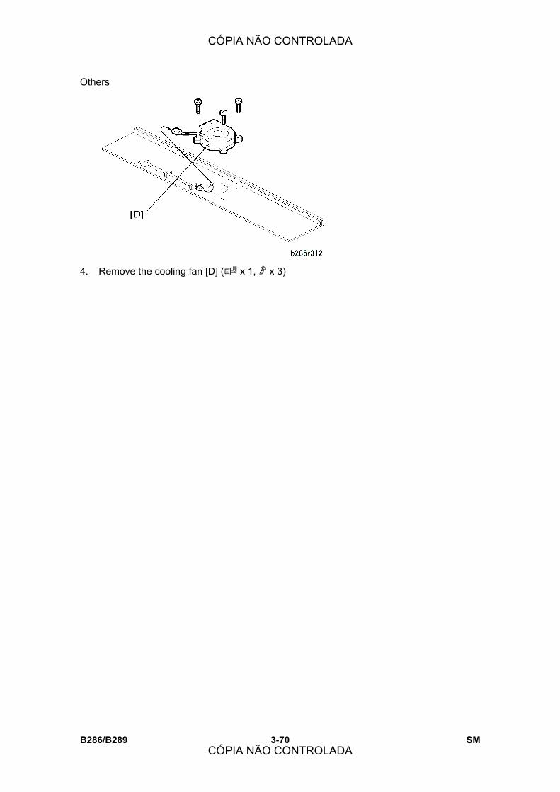
Others
B286/B289 3-70 SM
4. Remove the cooling fan [D] (# x 1, " x 3)
CÓPIA NÃO CONTROLADA
CÓPIA NÃO CONTROLADA
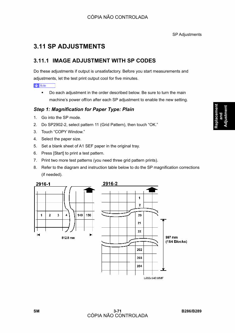
SP Adjustments
SM 3-71 B286/B289
Rep
lace
men
t an
d A
djus
tmen
t
3.11 SP ADJUSTMENTS
3.11.1 IMAGE ADJUSTMENT WITH SP CODES
Do these adjustments if output is unsatisfactory. Before you start measurements and
adjustments, let the test print output cool for five minutes.
! Do each adjustment in the order described below. Be sure to turn the main
machine�s power off/on after each SP adjustment to enable the new setting.
Step 1: Magnification for Paper Type: Plain 1. Go into the SP mode.
2. Do SP2902-2, select pattern 11 (Grid Pattern), then touch �OK.�
3. Touch �COPY Window.�
4. Select the paper size.
5. Set a blank sheet of A1 SEF paper in the original tray.
6. Press [Start] to print a test pattern.
7. Print two more test patterns (you need three grid pattern prints).
8. Refer to the diagram and instruction table below to do the SP magnification corrections
(if needed).
CÓPIA NÃO CONTROLADA
CÓPIA NÃO CONTROLADA
SP Adjustments
B286/B289 3-72 SM
SP Comments
2916-1
On each grid pattern measure the width from block 1 to block 150 (150
blocks) then average the three measurements. The width must be 812.8
mm. If the average measured width is not 812.8 mm, adjust this SP until
the width is 812.8 mm.
2916-2
On each grid pattern measure the length from block 21 to block 204 (184
blocks) then average the three measurements. The length must be 997
mm. If the measured length is not 997 mm, adjust this SP until the length
is 997 mm.
Step 2: Scanning Magnification 1. Make a 1:1 copy of the A0 SEF Magnification Chart with plain roll paper.
! You can use a different test chart, if it has lines 1000 mm long in the sub-scan
direction and 700 mm long in the main-scan direction.
2. Measure the length and width of the images on the original and the copy.
3. Do these SPs in the sequence shown in this table, if the measurements are not in the
standard range:
SP Standard Comments
4008 Less than ±0.5 Scanner Sub Scan Magnification
4101 Less than ±0.5 Scanner Main Scan Magnification
Step 3: Magnification for Paper Type: Translucent 1. Make a 1:1 copy of the A0 SEF Magnification Chart with translucent (tracing) paper.
! You can use a different test chart, if it has lines 1000 mm long in the sub-scan
direction and 700 mm long in the main-scan direction.
2. Measure the length and width of the images on the original and the copy.
3. Do the same measurements that you did for �Step 1: Magnification for Paper Type:
Plain.�
4. Do these SPs in the sequence shown in this table, if the measurements are not in the
CÓPIA NÃO CONTROLADA
CÓPIA NÃO CONTROLADA

SP Adjustments
SM 3-73 B286/B289
Rep
lace
men
t an
d A
djus
tmen
t
standard range:
SP Standard Comments
2916-3 Less than ±0.5 Fine Magnification � Translucent: Mode 1-4: Horiz
2916-4 Less than ±0.5 Fine Magnification � Translucent: Mode 1-4: Vert
Step 4: Magnification for Paper Type: Film 1. Make a 1:1 copy of the A0 SEF Magnification Chart with film.
! You can use a different test chart if it has lines 1000 mm long in the sub-scan
direction and 700 mm long in the main-scan direction.
2. Measure the length and width of the images on the original and the copy.
3. Do the same measurements for �Magnification for Paper Type: Plain.�
4. Do these SPs in the sequence shown in this table, if the measurements are not in the
standard range:
SP Standard Comments
2916-5 Less than ±0.5 Fine Magnification � Film: Mode 1-4: Horiz
2916-6 Less than ±0.5 Fine Magnification � Film: Mode 1-4: Vert
Step 5: Scanner Mask Setting
SP Set To: Comments
4012-5 0 Scanner Erase Margin DF � LEdge
4012-6 0 Scanner Erase Margin DF � TEdge
4012-7 0 Scanner Erase Margin DF � Left
4012-8 0 Scanner Erase Margin DF � Right
Step 6: Erase Margins Set these SPs to �5� to make measurement easier:
CÓPIA NÃO CONTROLADA
CÓPIA NÃO CONTROLADA

SP Adjustments
B286/B289 3-74 SM
SP Set To: Comments
2101-1 5 Print Erase Margin � Leading Edge
2101-2 5 Print Erase Margin � Trailing Edge
2101-3 5 Print Erase Margin � Left Edge
2101-4 5 Print Erase Margin � Right Edge
Step 7: Printer: Leading Edge, Side-to-Side Registration 1. Use a sheet of blank plain paper to print the IPU Printing test pattern (SP2902-2,
Pattern 11) for each paper feed station installed on the machine:
! Manual feed (bypass)
! Roll Feeder Roll 1
! Roll Feeder Roll 2
! Paper Cassette
2. Measure the gaps for the leading edge and side-to-side registration.
3. Touch �SP Mode� and adjust these SPs if a measurement is not in the standard range.
SP Standard: Comments
CÓPIA NÃO CONTROLADA
CÓPIA NÃO CONTROLADA
SP Adjustments
SM 3-75 B286/B289
Rep
lace
men
t an
d A
djus
tmen
t
SP Standard: Comments
1001-1 Leading Edge Registration � 1st Roll
1001-2 Leading Edge Registration � 2nd Roll
1001-3 Leading Edge Registration �Cassette
1001-5 Leading Edge Registration � By-pass Feed
1002-1 Side-to-Side Registration � 1st Roll
1002-2 Side-to-Side Registration � 2nd Roll
1002-3 Side-to-Side Registration �Cassette
1002-5
5 ±0.5 mm
Side-to-Side Registration � By-pass Feed
Step 8: Scanner Mask Setting Do these SPs to replace the �0� settings done in Step 5.
SP Set To: Comments
4012-5 Scanner Erase Margin DF � LEdge
4012-6 Scanner Erase Margin DF � TEdge
4012-7
1.5
Scanner Erase Margin DF � Left
4012-8 0.5 Scanner Erase Margin DF � Right
Step 9: Erase Margins Do these SPs to replace the settings done in Step 6.
SP Set To: Comments
2101-1 Print Erase Margin � Leading Edge
2101-2 Print Erase Margin � Trailing Edge
2101-3
2
Print Erase Margin � Left Edge
2101-4 0.5 Print Erase Margin � Right Edge
CÓPIA NÃO CONTROLADA
CÓPIA NÃO CONTROLADA

SP Adjustments
B286/B289 3-76 SM
Step 10: Scanner Registration 1. Use the A1 LEF Test Chart to make a 1:1 copy on plain A1 LEF paper.
2. On the copy, measure the gap between the chart image and the leading edge and left
edge.
3. Adjust these SPs if necessary:
SP Standard Comments
4010-1 ±3 mm Scanner Sub Scan Reg � Leading Edge
4011 ±2.8 mm Scanner Main Scan Reg
Step 11: Printer: Cut Length The following SPs are necessary for this step:
SP
1920-111 Cut Length Adjustment-1st Roll:297 mm (11� or 12�):Plain Paper
1920-115 Cut Length Adjustment-1st Roll:1189 mm (44� or 48�):Plain Paper
1920-211 Cut Length Adjustment-2nd Roll:297 mm (11� or 12�):Plain Paper
1920-215 Cut Length Adjustment-2nd Roll:1189 mm (44� or 48�):Plain Paper
! The cut length adjustment is done for all paper sizes after these settings are done.
! After these settings are done you may still need to do fine adjustments for each
paper size.
! SP1920-1 to 238 (Cut Length Adjustment)
1. Use the Preset Cut feature to make standard cuts of plain paper for these sizes:
Size Orientation
A3 Sideways
A1 Lengthways
CÓPIA NÃO CONTROLADA
CÓPIA NÃO CONTROLADA
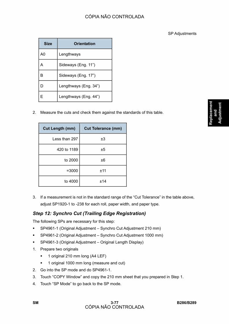
SP Adjustments
SM 3-77 B286/B289
Rep
lace
men
t an
d A
djus
tmen
t
Size Orientation
A0 Lengthways
A Sideways (Eng. 11�)
B Sideways (Eng. 17�)
D Lengthways (Eng. 34�)
E Lengthways (Eng. 44�)
2. Measure the cuts and check them against the standards of this table.
Cut Length (mm) Cut Tolerance (mm)
Less than 297 ±3
420 to 1189 ±5
to 2000 ±6
=3000 ±11
to 4000 ±14
3. If a measurement is not in the standard range of the �Cut Tolerance� in the table above,
adjust SP1920-1 to -238 for each roll, paper width, and paper type.
Step 12: Synchro Cut (Trailing Edge Registration) The following SPs are necessary for this step:
! SP4961-1 (Original Adjustment � Synchro Cut Adjustment 210 mm)
! SP4961-2 (Original Adjustment � Synchro Cut Adjustment 1000 mm)
! SP4961-3 (Original Adjustment � Original Length Display)
1. Prepare two originals
! 1 original 210 mm long (A4 LEF)
! 1 original 1000 mm long (measure and cut)
2. Go into the SP mode and do SP4961-1.
3. Touch �COPY Window� and copy the 210 mm sheet that you prepared in Step 1.
4. Touch �SP Mode� to go back to the SP mode.
CÓPIA NÃO CONTROLADA
CÓPIA NÃO CONTROLADA

SP Adjustments
B286/B289 3-78 SM
5. Do SP4961-3 to check the original scan length.
6. If the display is different, adjust with SP4961-1.
7. Do SP4961-2.
8. Touch �COPY Window� and scan the 1000 mm sheet that you prepared in Step 1.
9. Touch �SP Mode� to go back to the SP mode.
10. Do SP4961-3 to check the scan length.
11. If the display is different, adjust with SP4961-2.
Cut Length (mm) Cut Tolerance (mm)
Less than 297 ±4.50
to 594 ±5.00
to 841 ±6.00
to 1189 ±8.50
to 2000 ±18.0
to 3000 ±27.0
to 3600 ±33.0
3.11.2 CIS ADJUSTMENT WITH SP CODES
To Print the CIS Adjustment Pattern 1. Open the roll feeder drawer and cut off a sheet manually from a roll. (Turn the manual
feed knob to feed the paper, then push the cutter from side to side to cut.)
2. Close the roll feeder drawer.
3. Go into the �Copy SP� mode.
4. Do SP2902-2, select Pattern 11, then touch �OK.�
5. Touch �COPY Window� to go to the main screen.
6. On the operation panel, select one of the rolls for paper feed.
7. Put the blank sheet of paper on the original feed tray and feed it into the original feed
unit. Pattern 11 (grid pattern) prints.
8. Touch �SP Mode� to return to the SP mode.
9. Open SP4973, push [1] on the operation panel to change the setting from �0� to �1�,
then push [#]
CÓPIA NÃO CONTROLADA
CÓPIA NÃO CONTROLADA

SP Adjustments
SM 3-79 B286/B289
Rep
lace
men
t an
d A
djus
tmen
t
10. Touch �Exit� twice to leave the SP mode.
11. Select the paper roll size, then copy the grid pattern that you printed in Step 7 above.
! When you look at the printed pattern, the number sequence of the CIS joints is
opposite, with CIS-5 on the left through CIS-1 on the right as shown in the diagram
above.
! After completing the CIS adjustments, be sure to reset SP4973 to �0.�
To Adjust the Image at the CIS Joints 1. Check the printed pattern to find if the dots are aligned at CIS 1-2.
2. If they are aligned correctly, no adjustment is necessary.
� or-
If they are not aligned correctly, do the next step.
Here are two samples where the outputs are not aligned correctly.
! [A]: Distance between the lines at CIS 1-2 is wider than usual (as shown above). If
the distance between these lines is wider or narrower than the other lines, adjust
the main scan offset at CIS 1-2 with SP4972-1 (CIS Joint Adjustment �CIS 1-2
Main Scan) as described below.
! [B]: The lines at CIS 1-2 are broken. If the output from CIS 1 is lower (as shown
above) or higher, adjust the sub scan offset at CIS 1-2 with SP4972-11 (CIS Joint
CÓPIA NÃO CONTROLADA
CÓPIA NÃO CONTROLADA

SP Adjustments
B286/B289 3-80 SM
Adjustment � CIS 1-2 Sub Scan) as described below.
To adjust the main scan offset for Example [A]
Problem: Output from CIS 1 is too far to the right. 1. Do SP4972-1 and adjust the setting.
! Adjust the position of CIS 1. The position of CIS 2 does not move.
! If the area at the joint is too wide, set a smaller value.
! If the area at the joint is too narrow, set a larger value.
! In the example [A], you must set a smaller value.
To adjust the sub scan offset for Example [B]
Problem: Output from CIS 1 is lower than the output from CIS 2. 1. Do SP4972-11 and adjust the setting.
! Adjust the position of CIS 1. The position of CIS 2 does not move.
! If the CIS 1 area is higher than the CIS 2 area, set a larger value.
! If the CIS 1 area is lower than the CIS 2 area, set a smaller value.
! In the example shown [B], you must decrease the value for CIS 1.
After adjusting
1. Print one more pattern and check CIS 1-2.
2. Repeat these procedures until the image at CIS 1-2 is correct.
3. Do these procedures for the other joints (CIS 2-3, CIS 3-4, CIS 4-5)
! The �Effect� column in the table below tells you which area moves with the
adjustment, and which area does not move.
CÓPIA NÃO CONTROLADA
CÓPIA NÃO CONTROLADA
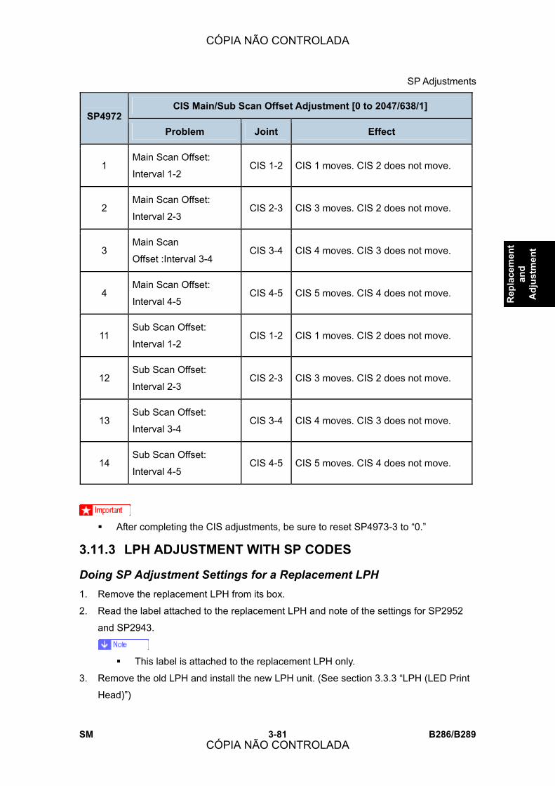
SP Adjustments
SM 3-81 B286/B289
Rep
lace
men
t an
d A
djus
tmen
t
CIS Main/Sub Scan Offset Adjustment [0 to 2047/638/1] SP4972
Problem Joint Effect
1 Main Scan Offset:
Interval 1-2 CIS 1-2 CIS 1 moves. CIS 2 does not move.
2 Main Scan Offset:
Interval 2-3 CIS 2-3 CIS 3 moves. CIS 2 does not move.
3 Main Scan
Offset :Interval 3-4 CIS 3-4 CIS 4 moves. CIS 3 does not move.
4 Main Scan Offset:
Interval 4-5 CIS 4-5 CIS 5 moves. CIS 4 does not move.
11 Sub Scan Offset:
Interval 1-2 CIS 1-2 CIS 1 moves. CIS 2 does not move.
12 Sub Scan Offset:
Interval 2-3 CIS 2-3 CIS 3 moves. CIS 2 does not move.
13 Sub Scan Offset:
Interval 3-4 CIS 3-4 CIS 4 moves. CIS 3 does not move.
14 Sub Scan Offset:
Interval 4-5 CIS 4-5 CIS 5 moves. CIS 4 does not move.
! After completing the CIS adjustments, be sure to reset SP4973-3 to �0.�
3.11.3 LPH ADJUSTMENT WITH SP CODES
Doing SP Adjustment Settings for a Replacement LPH 1. Remove the replacement LPH from its box.
2. Read the label attached to the replacement LPH and note of the settings for SP2952
and SP2943.
! This label is attached to the replacement LPH only.
3. Remove the old LPH and install the new LPH unit. (See section 3.3.3 �LPH (LED Print
Head)�)
CÓPIA NÃO CONTROLADA
CÓPIA NÃO CONTROLADA

SP Adjustments
B286/B289 3-82 SM
4. Do SP2952-1, -2 and enter the settings you read from the label attached to the LPH
replacement unit.
5. Do SP2943-1, -2, -3 and enter the settings you read from the label attached to the
replacement unit.
6. Print a test print in the IPU Test Pattern mode to make sure that the LPH joints are
aligned correctly. (See below.)
7. Do SP2902-2 to print IPU Test Pattern 10 to confirm that the LPH is functioning
normally (see the procedure below).
To Print Pattern IPU Test Pattern 10 1. Open the roll feeder drawer. Cut off a sheet manually from a roll.
2. Close the roll feeder drawer.
3. Go into the SP mode.
4. Do SP2902-2 (IPU Test Pattern. Press �Set� twice, select Pattern �10� then press �OK.�
5. Touch �COPY Window� to go to the copy display.
6. Select one of the rolls for paper feed.
7. Feed a blank sheet of paper into the machine then press [Start] print Pattern 10.
8. Check the printed pattern:
! If you see vertical white or black lines, do the vertical line adjustments (See the
next section, �Main Scan Adjustment: White, Black Vertical Lines�).
! If you see the areas are not aligned, do the misalignment adjustments (See below,
�To Adjust the LPH for Misalignment�).
! If you see vertical white/black lines and misalignment, do the vertical line
adjustment first.
CÓPIA NÃO CONTROLADA
CÓPIA NÃO CONTROLADA

SP Adjustments
SM 3-83 B286/B289
Rep
lace
men
t an
d A
djus
tmen
t
Main Scan Adjustment: White, Black Vertical Lines 1. Check the printed pattern at LPH 1-2 for white or black lines.
2. If there are no lines, no adjustment is necessary.
If you see white or black lines at LPH 1-2, go to the next step.
! White lines occur if too few LEDs come on at the joint.
! Black lines occur if too many LEDs come on at the joint.
3. Left line:
! If the left line is white, adjust SP2952-1 to a smaller value.
! If the left line is black, adjust SP2952-1 to a larger value.
4. Right line:
! If the right line is white, adjust SP2952-2 to a smaller value.
! If the right line is black, adjust SP2952-2 to a larger value.
5. After the adjustment, feed the blank sheet again to print one more pattern.
6. Check the results of the adjustment.
7. Do the adjustment again until the lines appear faint.
! The lines cannot be completely erased.
CÓPIA NÃO CONTROLADA
CÓPIA NÃO CONTROLADA

SP Adjustments
B286/B289 3-84 SM
Main Scan Adjustment: LED Light Level at LPH Joints After you do the previous procedure to adjust the main scan at the LPH joints, you can do a
fine adjustment on this area. To do this, you increase or decrease the intensity of the light
from the four LEDs at the joints.
�500� is the default setting for LPH 1-2 and LPH 2-3.
! If you change the 2nd digit of the value for LPH 1-2 (500 to 510) with SP2952-1, this
moves the four LEDs by one position to the left. ! If you change the 2nd digit of the value for LPH 2-3 (500 to 510) with SP2952-2, this
moves the four LEDs by one position to the right.
! If you change the 3rd digit of LPH 1-2 or LPH 2-3 (510 to 512, for example), this
increases the quantity of light from LEDs 1, 2, 3, 4 in the illustration.
The quantity of light can be adjusted for each LED independently with SP2953 (Power
Correction). But, this fine adjustment is usually not necessary in the field.
Adjusting LPH Alignment
Broken lines [A] or [B] in the IPU Test Pattern (SP2902-2, Pattern 11) indicate incorrect sub
scan timing at one or both joints.
1. Go into the SP mode, and do SP2952-11 for LPH 1-2
! Adjust the position of LPH 2 (LPH 1 does not move).
CÓPIA NÃO CONTROLADA
CÓPIA NÃO CONTROLADA

SP Adjustments
SM 3-85 B286/B289
Rep
lace
men
t an
d A
djus
tmen
t
! If LPH 2 is higher than LPH 1, set a larger value.
! If LPH 2 is lower than LPH 1, set a smaller value.
2. Print one more pattern with SP2952-11) and check the alignment at the joints.
3. Do this procedure again until the pattern at the joint is correct.
4. Do SP2952-12 for LPH 2-3
! Adjust the position of LPH 3 to LPH 2 (LPH 2 is the standard).
! If LPH 3 is higher than LPH 2, set a larger value.
! If LPH 3 is lower than LPH 2, set a smaller value.
5. Do this procedure again until the pattern at the joint is correct.
The hot roller and pressure roller have a slight spindle shape. The circumference at the
ends of the rollers [C] is slightly larger than the circumference at the centers [D]. This
arrangement ensures that there is always sufficient pressure on the paper between the
roller ends.
However, this difference in circumference also causes a small difference in the speed of
paper feed. The paper transport speed at the ends is slightly faster than at the center.
Because the centers of the rollers bend in slightly, this also increases the risk of slippage at
the center with paper narrower than 420 mm.
! For operators who frequently use paper wider than 420 mm, do the sub scan
adjustments for the LPH joints with SP2952-11, -12.
! For operators who frequently use paper that is less than 420 mm wide, do the sub
scan adjustments for the LPH joints with SP2952-51, -52 after you input the values of
SP 2952-11 and -12 from the decal.
CÓPIA NÃO CONTROLADA
CÓPIA NÃO CONTROLADA

SP Adjustments
B286/B289 3-86 SM
3.11.4 LPH DENSITY ADJUSTMENT WITH SP CODES
To Print the IPU Test Pattern 2 1. Open the roll feeder drawer. Cut off a sheet manually from a roll.
2. Close the roll feeder drawer.
3. Go into the SP mode.
4. Do 2902-2, select Pattern �2�, then touch �OK.�
5. Touch �COPY Window� to show the main screen.
6. On the operation panel, select one of the rolls for paper feed.
! You must select Tray 1 (1st Roll) or Tray 2 (2nd Roll). You cannot use �Auto
Paper Select.� If you select �Auto Paper Select� the pattern will not print.
7. Set the blank sheet of paper on the original feed tray.
8. Press [Start]. The pattern prints.
9. Touch �SP Mode� to return to the SP mode.
10. Check the density of the patterns in LPH 1, LPH 2, and LPH 3.
If density is equal for all areas, no adjustment is necessary. If the density is not equal,
do the next procedure.
CÓPIA NÃO CONTROLADA
CÓPIA NÃO CONTROLADA

SP Adjustments
SM 3-87 B286/B289
Rep
lace
men
t an
d A
djus
tmen
t
To Correct Pattern Density 1. Do SP2943-1, -2, and -3
! This SP makes the output of each LPH block brighter or darker.
2. Adjust the density for LPH 1 with SP2943-1.
! If the density is too dark, set a smaller value.
! If the density is too light, set a larger value.
3. Do SP2902-2, select Pattern #10, touch [OK], then print the pattern by feeding the
blank sheet and check the density.
4. Do this procedure for LPH2 and LPH3 until the density is the same in each of the three
sections.
! LPH2: SP2943-2
! LPH3: SP2943-3
CÓPIA NÃO CONTROLADA
CÓPIA NÃO CONTROLADA

CÓPIA NÃO CONTROLADA
CÓPIA NÃO CONTROLADA

TROUBLESHOOTING
CÓPIA NÃO CONTROLADA
CÓPIA NÃO CONTROLADA

CÓPIA NÃO CONTROLADA
CÓPIA NÃO CONTROLADA
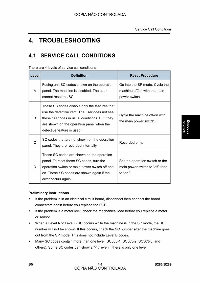
Service Call Conditions
SM 4-1 B286/B289
Trou
ble-
sh
ootin
g
4. TROUBLESHOOTING
4.1 SERVICE CALL CONDITIONS
There are 4 levels of service call conditions
Level Definition Reset Procedure
A
Fusing unit SC codes shown on the operation
panel. The machine is disabled. The user
cannot reset the SC.
Go into the SP mode. Cycle the
machine off/on with the main
power switch.
B
These SC codes disable only the features that
use the defective item. The user does not see
these SC codes in usual conditions. But, they
are shown on the operation panel when the
defective feature is used.
Cycle the machine off/on with
the main power switch.
C SC codes that are not shown on the operation
panel. They are recorded internally. Recorded only.
D
These SC codes are shown on the operation
panel. To reset these SC codes, turn the
operation switch or main power switch off and
on. These SC codes are shown again if the
error occurs again.
Set the operation switch or the
main power switch to �off� then
to �on.�
Preliminary Instructions
! If the problem is in an electrical circuit board, disconnect then connect the board
connectors again before you replace the PCB.
! If the problem is a motor lock, check the mechanical load before you replace a motor
or sensor.
! When a Level A or Level B SC occurs while the machine is in the SP mode, the SC
number will not be shown. If this occurs, check the SC number after the machine goes
out from the SP mode. This does not include Level B codes.
! Many SC codes contain more than one level (SC303-1, SC303-2, SC303-3, and
others). Some SC codes can show a �-1,� even if there is only one level.
CÓPIA NÃO CONTROLADA
CÓPIA NÃO CONTROLADA

Service Call Conditions
B286/B289 4-2 SM
The following abbreviations are used in these SC tables:
! (F) means �Front�
! (R) means �Rear�
CÓPIA NÃO CONTROLADA
CÓPIA NÃO CONTROLADA
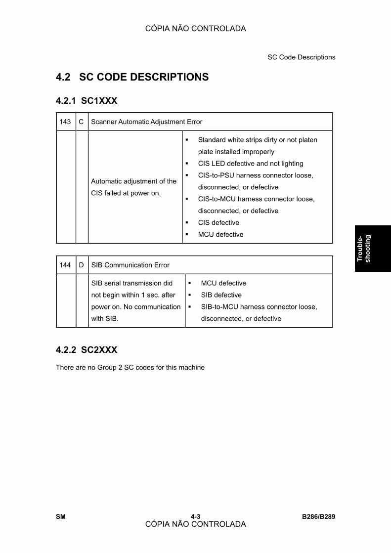
SC Code Descriptions
SM 4-3 B286/B289
Trou
ble-
sh
ootin
g
4.2 SC CODE DESCRIPTIONS
4.2.1 SC1XXX
143 C Scanner Automatic Adjustment Error
Automatic adjustment of the
CIS failed at power on.
! Standard white strips dirty or not platen
plate installed improperly
! CIS LED defective and not lighting
! CIS-to-PSU harness connector loose,
disconnected, or defective
! CIS-to-MCU harness connector loose,
disconnected, or defective
! CIS defective
! MCU defective
144 D SIB Communication Error
SIB serial transmission did
not begin within 1 sec. after
power on. No communication
with SIB.
! MCU defective
! SIB defective
! SIB-to-MCU harness connector loose,
disconnected, or defective
4.2.2 SC2XXX
There are no Group 2 SC codes for this machine
CÓPIA NÃO CONTROLADA
CÓPIA NÃO CONTROLADA

SC Code Descriptions
B286/B289 4-4 SM
4.2.3 SC3XXX
Group 3 SC codes are related to image making.
Charge Corona Output Error
300 D After sampling at 10 ms intervals, the
charge-corona feedback voltage
remained less than 0.5 V for more
than 200 ms.
! Charge corona unit defective
! High voltage cable defective
! Corona wire dirty or defective
! CGB power pack fuse,
connections loose, broken, or
defective
! CGB power pack defective
305 D Charge Corona Wire Cleaner Error
The charge wire cleaner did not: (1)
come from the home position within 5
s, or (2) did return to the home
position within 3.75 s due to wire
cleaner overload.
! Cleaner unit blocked or damaged
! Until replacement parts become
available, set SP2804 to �0� to
disable the charge-corona
cleaning function so the machine
can operate.
392 D Development Bias Error
The development bias feedback voltage
was less than 0.3 V for longer than 200
ms while the PWM duty value was more
than 5% (indicating a development bias
leak).
! Bias terminal damaged
! High voltage cable damaged,
defective
! CGB power pack defective
CÓPIA NÃO CONTROLADA
CÓPIA NÃO CONTROLADA

SC Code Descriptions
SM 4-5 B286/B289
Trou
ble-
sh
ootin
g
4.2.4 SC4XXX
Group 4 SC codes are also related to image making.
400 D ID Sensor Auto Adjustment Error
Vsg did not reach 4 ±0.2 V when
the ID sensor was initialized with
SP3001-2.
! ID sensor dirty
! ID sensor harness, connector loose,
disconnected, damaged, defective
! ID sensor defective
! MCU defective
! Development unit defective
! CGB power pack defective
401 D ID Sensor Vsg Error
The Vsg level was twice detected
lower than 2.5 V.
-or-
The Vsg level was once detected
higher than 4.8V.
! ID sensor dirty
! ID sensor harness, connector loose,
disconnected, damaged, defective
! ID sensor defective
! MCU defective
! CGB power pack defective
402 D ID Sensor Vsp Error
The Vsp level was twice detected at 0V or
at more than 2.5 V.
! Under the left upper cover,
make sure that the hex screw
of the main drum drive gear is
tight
! ID sensor dirty
! ID sensor harness, connector
loose, disconnected,
damaged, defective
! ID sensor defective
! MCU defective
! Development unit defective
! CGB power pack defective
CÓPIA NÃO CONTROLADA
CÓPIA NÃO CONTROLADA

SC Code Descriptions
B286/B289 4-6 SM
440 D Transfer Output Error
A high voltage feedback
voltage of less than 0.5 V was
detected for 200 ms.
! High voltage cable disconnected,
damaged
! T/S power pack defective
460 D DC Separation Corona Output Error
A dc separation feedback voltage of
less than 0.5 V was detected after
more than 200 ms.
! High voltage cable disconnected,
damaged
! T/S power pack defective
4.2.5 SC5XXX
508 B Cutter Error
The left and right cutter HP
sensors remained on or off
more than 2 sec.
! HP sensors on the left and right side
loose, disconnected, defective
! Cutter motor harness damaged,
defective
! HP sensors defective
! Cutter motor defective
Note: Paper can be fed from the bypass table
if the roll feeder or paper cassette is not
operationg.
520 D Main Motor Error
After the motor started, the main
motor lock signal remained HIGH for
5 sec.
! Physical obstruction blocking motor
! Motor harness damaged, defective
! Motor defective
CÓPIA NÃO CONTROLADA
CÓPIA NÃO CONTROLADA
SC Code Descriptions
SM 4-7 B286/B289
Trou
ble-
sh
ootin
g
521 D Drum Motor Error
After the motor started, the drum
motor lock signal remained HIGH for
5 sec.
! Physical obstruction blocking motor
! Motor harness damaged, defective
! Motor defective
522 D Fusing Unit Drive Motor Error
After the motor started, the fusing
motor lock signal remained HIGH for
5 sec.
! Physical obstruction blocking motor
! Motor harness damaged, defective
! Motor defective
530 D Fusing Unit Ventilation Fan Error
After the motor started, the fan motor
lock signal remained HIGH for 5 sec.
! Physical obstruction blocking motor
! Motor harness damaged, defective
! Motor defective
541 A Fusing Thermistor Errors
The thermistor measured the hot
roller temperature every 1 sec. for 30
sec. and the temperature remained
below 5oC (54oF).
! Thermistor positioned incorrectly
! Thermistor cable loose,
disconnected, damaged
! Thermistor defective
CÓPIA NÃO CONTROLADA
CÓPIA NÃO CONTROLADA
SC Code Descriptions
B286/B289 4-8 SM
542 A Fusing Temperature Warm-up Error
The hot roller did not reach the ready
temperature within 4 min. 30 sec.
after power on.
-or-
After 5 sec. and 5 rotations of the hot
roller, the machine detected that the
temperature rise was less than 3oC .
! Fusing lamp connections loose,
broken, defective
! Fusing lamp defective
! Thermistor not touching the hot
roller
! Thermistor defective
! MCU defective
The ready temperature is determined by the state of the machine at recovery:
! Ready Temp. = Target Fusing Temp. (if power on or recovery starts when
the hot roller is 80°C or higher).
! Ready Temp. = Target Fusing Temp. � 10°C (SP1105-1 default) if power
on or recovery starts when the hot roller is less that 80°C.
! Ready Temp. = Target Fusing Temp. � 20°C (SP1937-3 default) if power
on or recovery starts with pressure roller inching control on.
543 A Fusing Lamp Overheated: Error 1
The circuit on the MCU that monitors the
temperature of the board detected a fusing
temperature of 230oC (446oF) for longer than 2
sec.
! MCU defective
545 A Fusing Lamp Overheated: Error 2
After the hot roller reached the
ready temperature, the fusing
lamp stayed on at full power for
50 sec. while the hot roller was
not rotating.
! Hot roller thermistor not positioned
correctly
! Fusing lamp harness loose,
disconnected, defective
! MCU defective
CÓPIA NÃO CONTROLADA
CÓPIA NÃO CONTROLADA
SC Code Descriptions
SM 4-9 B286/B289
Trou
ble-
sh
ootin
g
546 A Fusing Temperature Errors
The machine detected that the fusing
temperature was fluctuating out of
range for more than 60 sec. (7
readings detected temperature
fluctuating more than ±20oC)
! Thermistor connection loose,
disconnected, defective
! Hot roller thermistor not positioned
correctly
! Fusing lamp connections loose,
disconnected, defective
! MCU defective
547 D Zero-Cross Signal Errors
This error occurs if the machine fails
to detect 50/60 Hz on the power
supply line.
Note: The zero-cross signal from the
ac power supply generates a trigger
pulse to control the power supply of
power. (It automatically detects 50/60
Hz.)
! Check that the frequency of the
power supply to the machine is
correct
! PSU defective
! MCU defective
551 A Pressure roller center thermistor error 1
During the hot roller temperature
control sequence, or while the hot
roller and pressure roller were
rotating, the pressure roller center
thermistor measured a value
higher than 3.3V 10 consecutive
times at 600 ms intervals.
! Pressure roller center thermistor not
positioned properly
! Pressure roller center thermistor
connector loose, broken, defective
! Pressure roller center thermistor
defective
! MCU defective
CÓPIA NÃO CONTROLADA
CÓPIA NÃO CONTROLADA

SC Code Descriptions
B286/B289 4-10 SM
553 A Pressure roller center thermistor error 2
During the hot roller
temperature control sequence,
the pressure roller center
thermistor measures a value
lower than 0.2V.
! Pressure roller center thermistor not
positioned properly
! Pressure roller center thermistor
connector loose, broken, defective
! Pressure roller center thermistor
defective
! MCU defective
557 C Applied zero-cross waveform error
The applied power ac frequency was
detected less than 66 Hz more than
10 times.
! Noise on the ac power supply
line
559 A Fusing paper jam errors
Three consecutive paper jam errors
occurred in the fusing unit.
Note: This SC code is not issued
unless SP1159 is switched on.
! Paper jam in fusing unit
! Pick-off pawl defective
! Paper scraps in fusing unit
! Exit sensor defective
561 A Pressure roller end thermistor error 1
During the hot roller temperature
control sequence, or while the hot
roller and pressure roller were
rotating, the end thermistor on the
pressure roller returned a digital
reading of more than 3.3V.
! Pressure roller end thermistor not
positioned properly
! Pressure roller end thermistor
connector loose, broken, defective
! Pressure roller end thermistor
defective
! MCU defective
CÓPIA NÃO CONTROLADA
CÓPIA NÃO CONTROLADA

SC Code Descriptions
SM 4-11 B286/B289
Trou
ble-
sh
ootin
g
563 A Pressure roller end thermistor error 2
During the hot roller
temperature control
sequence, the end
thermistor on the pressure
roller returned a digital
reading of less than 0.2V.
! Pressure roller end thermistor connector
loose
! Pressure roller end thermistor short circuit,
defective
! MCU defective
4.2.6 SC6XXX
628 D Fan fold unit communication error 1
The machine failed to detect within 100
ms a response to a data frame sent to
the fan fold unit. Three consecutive
retries failed, resulting in a timeout.
! Cable harness between the
main machine and fan fold unit
broken or defective
! Connector loose, disconnected,
or defective
B Key/card counter device error 1
632
After 1 data frame is sent to the device, an
ACK signal is not received within 100 ms,
and is not received after 3 retries.
! Serial line from the device
to the main machine is
unstable, disconnected, or
defective.
Key/card counter device error 2
633 B During communication with the device,
the MCU received a break (Low) signal.
! Serial line from the device to
the main machine is unstable,
disconnected, or defective
CÓPIA NÃO CONTROLADA
CÓPIA NÃO CONTROLADA
SC Code Descriptions
B286/B289 4-12 SM
Key/card counter device error 3
634 B The backup battery of the counter
device RAM is low.
! RAM backup battery
exhausted
! Counter device defective
Key/card counter device error 4
635 B After installation of the device a
message alerts user to a battery voltage
abnormal error.
! Device control board defective
! Device control board backup
battery defective
650 B @Remote communication error 1
A dial-up or modem error
occurred during @Remote
operation. (This error occurs only
during @Remote operation.)
! Modem line disconnected
! Modem board missing or not properly
installed
651 C @Remote communication error 2
An illegal dial-up to the service
center was attempted by
@Remote.
! Software bug
D Engine startup error
670
The MCU failed to respond
within the prescribed time
when the machine was turned
on.
! Connections between MCU and
controller board are loose,
disconnected, or damaged
! MCU defective
! Controller board defective
CÓPIA NÃO CONTROLADA
CÓPIA NÃO CONTROLADA

SC Code Descriptions
SM 4-13 B286/B289
Trou
ble-
sh
ootin
g
D Controller startup error
672
After power on, the line between the
controller and the operation panel did
not open for normal operation.
-or-
After normal startup, communication
with the controller stopped.
! Controller installed incorrectly
! Controller board defective
! Operation panel harness
disconnected or defective
690 D VDB communication error
There was no serial communication with
the VDB within 1 sec. after power on.
! VDB-to-MCU harness or
connectors broken, loose,
defective
! VDB defective
! MCU defective
CÓPIA NÃO CONTROLADA
CÓPIA NÃO CONTROLADA

SC Code Descriptions
B286/B289 4-14 SM
4.2.7 SC7XXX
720 D Fan folder transport motor error
A transport motor lock
signal was detected for
more than 5 sec. while
the motor was running.
! Transport motor harness connector loose,
disconnected, broken
! Motor overload due to an obstruction
! Transport motor defective
! Fan folder unit MCU defective
762 D Front fold plate HP sensor error
The state (on/off, off/on) of
the front fold plate HP sensor
in the fan fold unit did not
change 1 sec. after the plate
started to move.
! Fold plate motor (F) harness connector
loose, disconnected, broken
! Front fold plate HP sensor harness
connector loose, disconnected, broken
! Fold plate motor (F) defective
! Front fold plate HP sensor defective
! Undetected paper is jamming the action
of the motor or fold plate
! Fan folder unit MCU defective
763 D Rear fold plate HP sensor error
The state (on/off, off/on) of
the rear fold plate HP sensor
in the fan fold unit did not
change 1 sec. after the plate
started to move.
! Fold plate motor (R) arness connector
loose, disconnected, broken
! Rear fold plate HP sensor harness
connector loose, disconnected, broken
! Fold plate motor (R) defective
! Rear fold plate HP sensor defective
! Undetected paper is jamming the action
of the motor or fold plate
! Fan folder unit MCU defective
CÓPIA NÃO CONTROLADA
CÓPIA NÃO CONTROLADA

SC Code Descriptions
SM 4-15 B286/B289
Trou
ble-
sh
ootin
g
790 D PCB fan error: Folder Unit
The machine detected a
continuous lock signal from
the PCB cooling fan on the
PSU for 20 sec.
! Fan harness connector loose,
disconnected, broken
! Overload on the fan motor due to physical
obstruction such has undetected paper,
etc.
! Fan defective
! MCU folder unit defective
CÓPIA NÃO CONTROLADA
CÓPIA NÃO CONTROLADA

SC Code Descriptions
B286/B289 4-16 SM
4.2.8 SC8XXX
819 C Fatal kernel error
Due to a control error, a RAM
overflow occurred during system
processing.
! Controller board defective
! Insufficient memory
! Expanded memory defective
Note: For more details about this SC code error, execute SP5990 to print an SMC report so
that you can read the error code. The error code is not displayed on the operation panel.
Self-Diagnostic Error: CPU
820 D The CPU returned an
unexpected error during the
self-diagnostic test.
! Controller board defective
! Insufficient memory
! Expanded memory defective
Self-diagnostic error 2: ASIC
821 D
The ASIC provides the central point
for the control of bus arbitration for
CPU access, for option bus and
SDRAM access, for SDRAM refresh,
and for management of the internal
bus gate.
! Controller board defective
Note: For more details about this SC code error, execute SP5990 to print an SMC report so
that you can read the error code. The error code is not displayed on the operation panel.
822 B Self-diagnostic error 3: HDD
An error occurred when the self-check
was performed when the machine
was switched on after the HDD was
replaced. (The diagnostic command
was issued to the HDD device but the
result was an error).
! HDD defective
! HDD harness disconnected,
defective
! Controller board defective
CÓPIA NÃO CONTROLADA
CÓPIA NÃO CONTROLADA

SC Code Descriptions
SM 4-17 B286/B289
Trou
ble-
sh
ootin
g
Self-diagnostic Error: NIB
823 B The network interface board returned
an error during the self-diagnostic test.
! Network interface board
defective
! Controller board defective
Self-diagnostic error 4: NVRAM
824 D Error occurred because:
! NVRAM device does not exist
! NVRAM device is damaged
! NVRAM socket damaged
! NVRAM defective
Self-diagnostic Error 5: RTC/Optional NVRAM
826 D The NVRAM or optional NVRAM
returned an error during the
self-diagnostic test.
! Make sure NVRAM is seated
correctly in its socket
! Replace the NVRAM on the
controller board
Self-diagnostic error 6: Resident RAM
827 D The resident RAM returned a verify error
during the self-diagnostic test.
! Controller board defective
! Replace RAM DIMM
Self-diagnostic error 8: ROM
828 D Measuring the CRC for the boot monitor
and operating system program resulted
in an error.
! Software defective
! Controller board defective
CÓPIA NÃO CONTROLADA
CÓPIA NÃO CONTROLADA
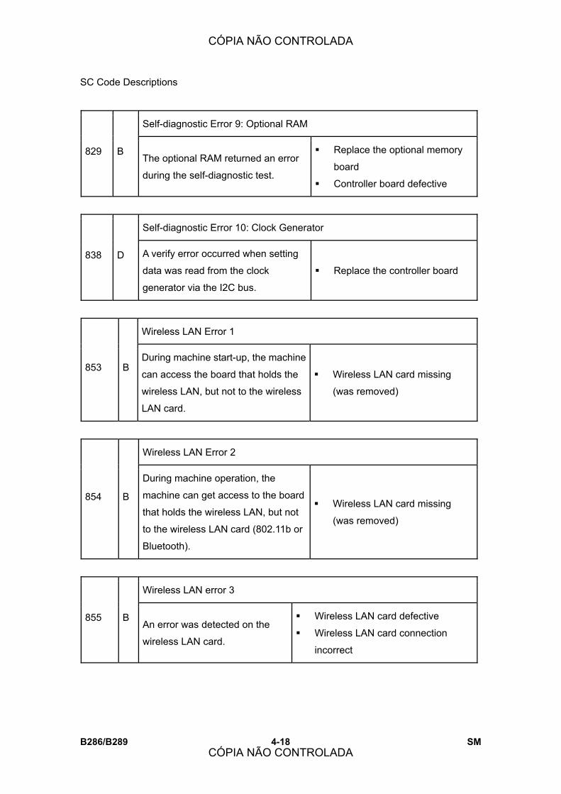
SC Code Descriptions
B286/B289 4-18 SM
Self-diagnostic Error 9: Optional RAM
829 B The optional RAM returned an error
during the self-diagnostic test.
! Replace the optional memory
board
! Controller board defective
Self-diagnostic Error 10: Clock Generator
838 D A verify error occurred when setting
data was read from the clock
generator via the I2C bus.
! Replace the controller board
Wireless LAN Error 1
853 B During machine start-up, the machine
can access the board that holds the
wireless LAN, but not to the wireless
LAN card.
! Wireless LAN card missing
(was removed)
Wireless LAN Error 2
854 B
During machine operation, the
machine can get access to the board
that holds the wireless LAN, but not
to the wireless LAN card (802.11b or
Bluetooth).
! Wireless LAN card missing
(was removed)
Wireless LAN error 3
855 B An error was detected on the
wireless LAN card.
! Wireless LAN card defective
! Wireless LAN card connection
incorrect
CÓPIA NÃO CONTROLADA
CÓPIA NÃO CONTROLADA

SC Code Descriptions
SM 4-19 B286/B289
Trou
ble-
sh
ootin
g
Wireless LAN error 4
856 B An error was detected on the
wireless LAN board.
! Wireless LAN board defective
! PCI connector to MB loose
USB I/F Error
857 B The USB driver is not stable and
caused an error.
! Poor USB card connection
! Replace the controller board
HDD startup error at power on
860 B
HDD is connected but a driver error is
detected.
-or-
The driver does not respond with the status
of the HDD within 30 s.
! HDD is not initialized
! Level data corrupted
! HDD is defective
HDD re-try failure
861 D
At power on the HDD was detected.
Power supply to the HDD was
interrupted after the system entered
the energy save mode, but after the
HDD was awakened from the energy
save mode it did not return to the
ready status within 30 sec.
! Harness between HDD and
controller board disconnected,
defective
! HDD power connector
disconnected
! HDD defective
! Controller board defective
CÓPIA NÃO CONTROLADA
CÓPIA NÃO CONTROLADA

SC Code Descriptions
B286/B289 4-20 SM
HDD data read failure
863 D The data written to the HDD cannot be read
normally, due to bad sectors generated during
operation.
! HDD defective
Note:
! If the bad sectors are generated at the image partition, the bad sector information is
written to NVRAM.
! The next time the HDD is accessed, these bad sectors will not be accessed for
read/write operation. The HDD will probably require replacement soon.
HDD data CRC error
864 D During HDD operation, the HDD cannot respond
to a CRC error query. Data transfer did not
execute normally while data was being written to
the HDD.
! HDD defective
HDD access error
865 D HDD responded to an error during
operation for a condition other than those
for SC863, 864.
! HDD defective
SD card error 1: Confirmation error
866 B The machine detected an electronic license
error in the application on the SD card in
the controller slot immediately after the
machine was turned on.
! Program missing from the
SD card
CÓPIA NÃO CONTROLADA
CÓPIA NÃO CONTROLADA
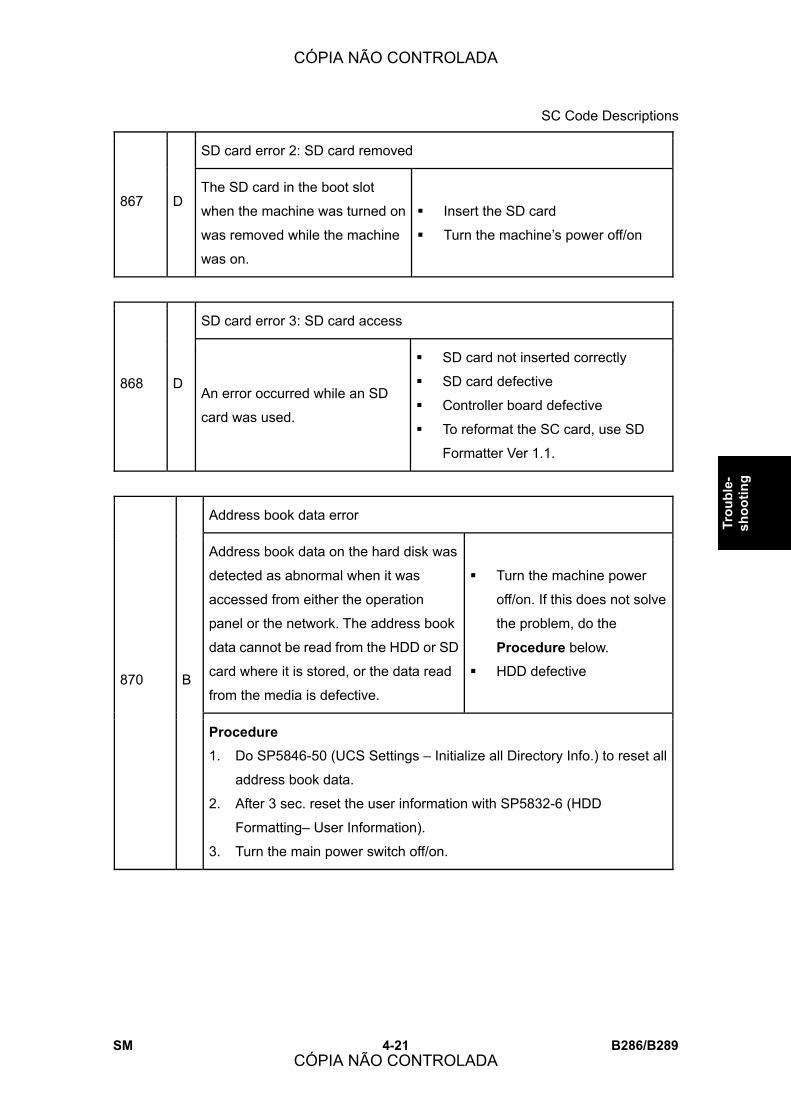
SC Code Descriptions
SM 4-21 B286/B289
Trou
ble-
sh
ootin
g
SD card error 2: SD card removed
867 D The SD card in the boot slot
when the machine was turned on
was removed while the machine
was on.
! Insert the SD card
! Turn the machine�s power off/on
SD card error 3: SD card access
868 D An error occurred while an SD
card was used.
! SD card not inserted correctly
! SD card defective
! Controller board defective
! To reformat the SC card, use SD
Formatter Ver 1.1.
Address book data error
Address book data on the hard disk was
detected as abnormal when it was
accessed from either the operation
panel or the network. The address book
data cannot be read from the HDD or SD
card where it is stored, or the data read
from the media is defective.
! Turn the machine power
off/on. If this does not solve
the problem, do the
Procedure below.
! HDD defective 870 B
Procedure
1. Do SP5846-50 (UCS Settings � Initialize all Directory Info.) to reset all
address book data.
2. After 3 sec. reset the user information with SP5832-6 (HDD
Formatting� User Information).
3. Turn the main power switch off/on.
CÓPIA NÃO CONTROLADA
CÓPIA NÃO CONTROLADA

SC Code Descriptions
B286/B289 4-22 SM
HDD mail send data error
873 B
An error was detected on the
HDD immediately after the
machine was turned on, or power
was turned off while the machine
used the HDD.
! Do SP5832 (Format HDD � Mail TX
Data) to initialize the HDD
! Replace the HDD
Delete All error 1: HDD
874 D
A data error was detected for the
HDD/NVRAM after the Delete All
option was used.
Note: The source of this error is
the Data Overwrite Security Unit
B735 running from the DOS SD
card.
! Turn the main switch off/on, do the
operation again.
! Install the Data Overwrite Security
Unit again.
! HDD defective
Delete All error 2: Data area
875 D
An error occurred when the machine
deleted data from the HDD.
Note: The source of this error is the
Data Overwrite Security Unit B735
running from the DOS SD card.
! Turn the main switch off/on
and try the operation again.
File Format Converter (MLB) error
880 B A request to access the MLB was not
answered within the specified time (60
sec.).
! File format converter board
defective
CÓPIA NÃO CONTROLADA
CÓPIA NÃO CONTROLADA
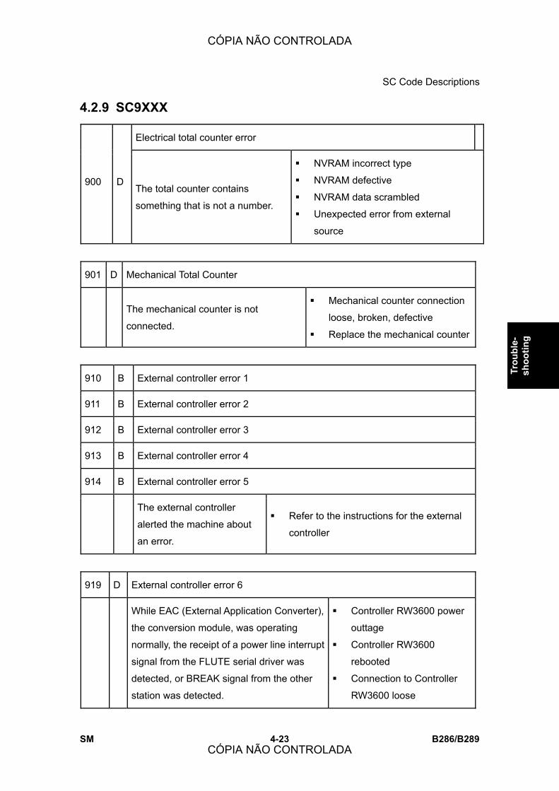
SC Code Descriptions
SM 4-23 B286/B289
Trou
ble-
sh
ootin
g
4.2.9 SC9XXX
Electrical total counter error
900 D The total counter contains
something that is not a number.
! NVRAM incorrect type
! NVRAM defective
! NVRAM data scrambled
! Unexpected error from external
source
901 D Mechanical Total Counter
The mechanical counter is not
connected.
! Mechanical counter connection
loose, broken, defective
! Replace the mechanical counter
910 B External controller error 1
911 B External controller error 2
912 B External controller error 3
913 B External controller error 4
914 B External controller error 5
The external controller
alerted the machine about
an error.
! Refer to the instructions for the external
controller
919 D External controller error 6
While EAC (External Application Converter),
the conversion module, was operating
normally, the receipt of a power line interrupt
signal from the FLUTE serial driver was
detected, or BREAK signal from the other
station was detected.
! Controller RW3600 power
outtage
! Controller RW3600
rebooted
! Connection to Controller
RW3600 loose
CÓPIA NÃO CONTROLADA
CÓPIA NÃO CONTROLADA
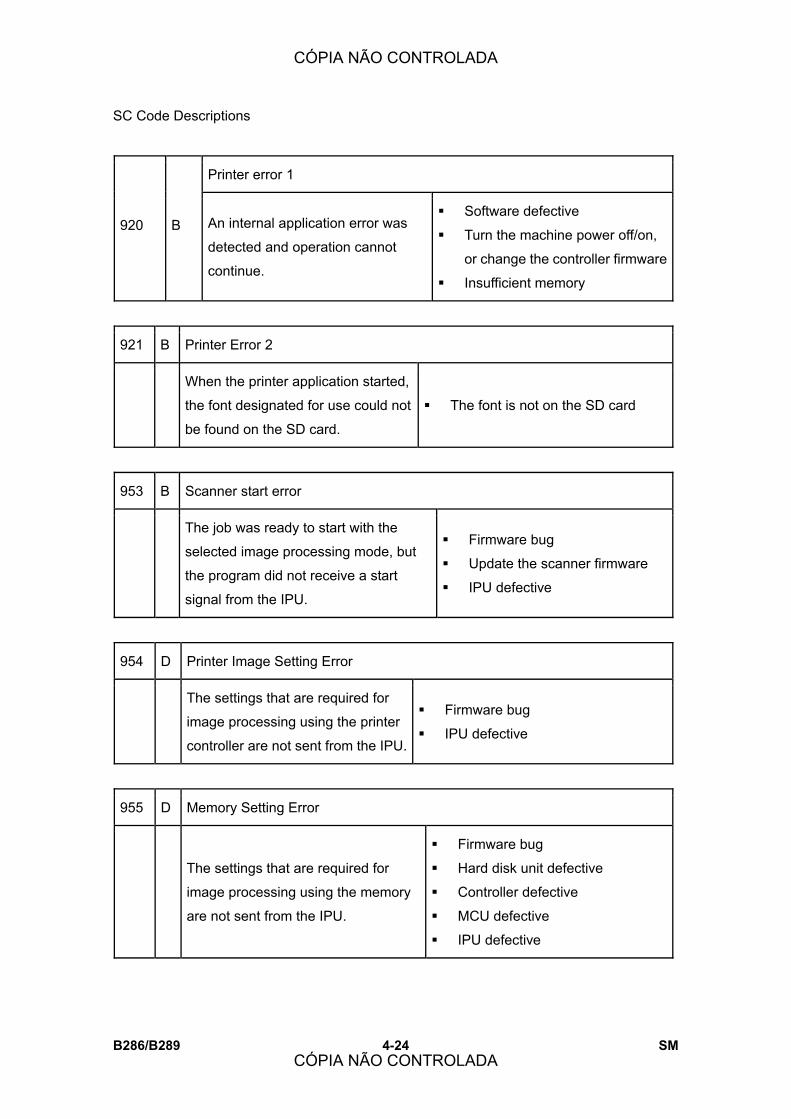
SC Code Descriptions
B286/B289 4-24 SM
Printer error 1
920 B An internal application error was
detected and operation cannot
continue.
! Software defective
! Turn the machine power off/on,
or change the controller firmware
! Insufficient memory
921 B Printer Error 2
When the printer application started,
the font designated for use could not
be found on the SD card.
! The font is not on the SD card
953 B Scanner start error
The job was ready to start with the
selected image processing mode, but
the program did not receive a start
signal from the IPU.
! Firmware bug
! Update the scanner firmware
! IPU defective
954 D Printer Image Setting Error
The settings that are required for
image processing using the printer
controller are not sent from the IPU.
! Firmware bug
! IPU defective
955 D Memory Setting Error
The settings that are required for
image processing using the memory
are not sent from the IPU.
! Firmware bug
! Hard disk unit defective
! Controller defective
! MCU defective
! IPU defective
CÓPIA NÃO CONTROLADA
CÓPIA NÃO CONTROLADA
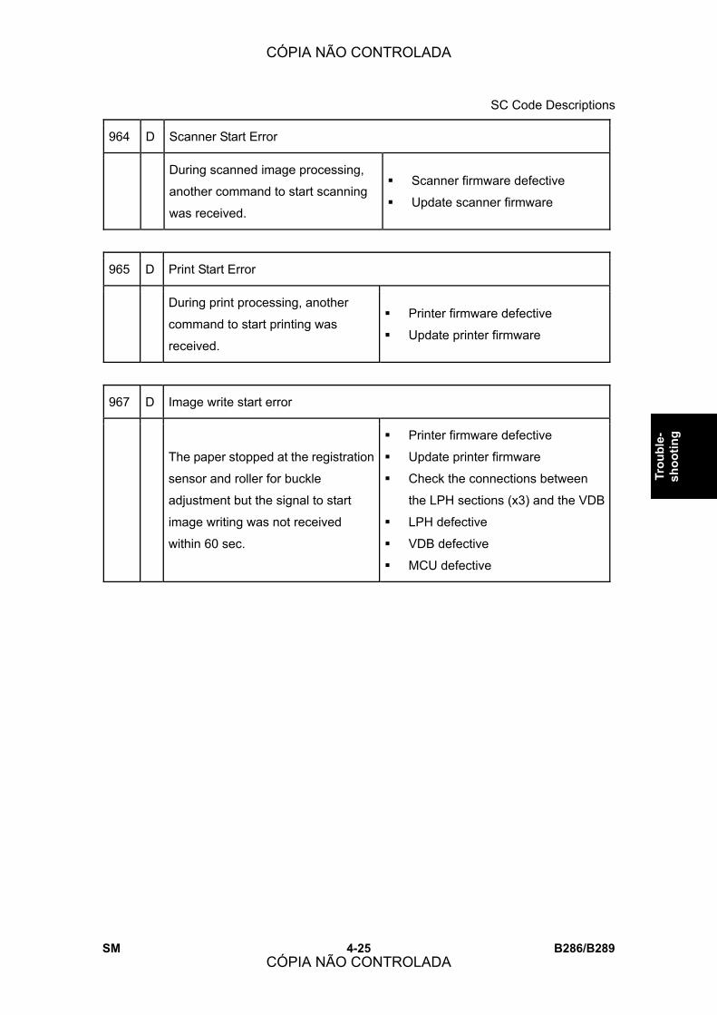
SC Code Descriptions
SM 4-25 B286/B289
Trou
ble-
sh
ootin
g
964 D Scanner Start Error
During scanned image processing,
another command to start scanning
was received.
! Scanner firmware defective
! Update scanner firmware
965 D Print Start Error
During print processing, another
command to start printing was
received.
! Printer firmware defective
! Update printer firmware
967 D Image write start error
The paper stopped at the registration
sensor and roller for buckle
adjustment but the signal to start
image writing was not received
within 60 sec.
! Printer firmware defective
! Update printer firmware
! Check the connections between
the LPH sections (x3) and the VDB
! LPH defective
! VDB defective
! MCU defective
CÓPIA NÃO CONTROLADA
CÓPIA NÃO CONTROLADA

SC Code Descriptions
B286/B289 4-26 SM
Software error 1
990 D The software performs an
unexpected function and the
program cannot continue.
! Firmware defective: re-boot
! Update firmware*1
Software error 2
991 C The software performs an
unexpected function. However,
unlike SC990, recovery processing
allows the program to continue.
Software defective, re-boot*1
*1: For more information about SC990 and SC991:
1. Execute SP7403 or print an SMC Report (SP5990) to read the history of the 10 most
recent logged errors.
2. If you press [0] on the operation panel with the SP selection menu displayed, you will
see detailed information about the recently logged SC990 or SC991 errors, including
the software file name, line number, and so on. (1) above is the recommended method,
because another SC could write over the information for the previous SC.
992 D Erratic SC error
There was an unusual operation by the
software because of:
! An incorrect argument in the
program.
! An incorrect internal parameter.
! Work memory not sufficient.
! An error occurred that could not be
detected by other SC codes.
! Turn the main power switch
off/on.
! Go into the SP mode. Do
SP7901 to display details about
SC992 (software file name, line
number, and variable), and
inform your supervisor of the
results.
CÓPIA NÃO CONTROLADA
CÓPIA NÃO CONTROLADA

SC Code Descriptions
SM 4-27 B286/B289
Trou
ble-
sh
ootin
g
B Cannot select application function
997
An application did not start after
the user pushed the correct key
on the operation panel.
! Software bug
! A RAM or DIMM option required for
the application is not installed or
not installed correctly.
D Application cannot start
998
Register processing does not
operate for an application within
60 s after the machine power is
turned on. No applications start
correctly, and all end
abnormally.
! Software bug
! A RAM or DIMM option needed for
the application not installed, or not
installed correctly
! Controller board defective
CÓPIA NÃO CONTROLADA
CÓPIA NÃO CONTROLADA

Jam Code Tables
B286/B289 4-28 SM
4.3 JAM CODE TABLES
4.3.1 OVERVIEW
When a jam occurs:
! The jam indicator lights (!).
! A diagram on the LCD shows the location of the jam with instructions about how to
correct the problem.
! The �Code� numbers in the table are also shown. Use SP 7507 (Plotter Jam History) to
see the most recent codes.
Code Location Code Location
A1 Paper Cassette Feed N3 Folder unit junction gate
A2 Roll Paper Feed N5 Fan folder entrance
B Bypass Paper Feed, Paper
Registration N7 Fan folder exit
CÓPIA NÃO CONTROLADA
CÓPIA NÃO CONTROLADA
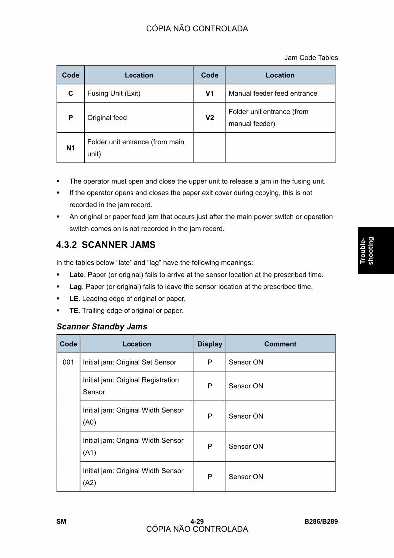
Jam Code Tables
SM 4-29 B286/B289
Trou
ble-
sh
ootin
g
Code Location Code Location
C Fusing Unit (Exit) V1 Manual feeder feed entrance
P Original feed V2 Folder unit entrance (from
manual feeder)
N1 Folder unit entrance (from main
unit)
! The operator must open and close the upper unit to release a jam in the fusing unit.
! If the operator opens and closes the paper exit cover during copying, this is not
recorded in the jam record.
! An original or paper feed jam that occurs just after the main power switch or operation
switch comes on is not recorded in the jam record.
4.3.2 SCANNER JAMS
In the tables below �late� and �lag� have the following meanings:
! Late. Paper (or original) fails to arrive at the sensor location at the prescribed time.
! Lag. Paper (or original) fails to leave the sensor location at the prescribed time.
! LE. Leading edge of original or paper.
! TE. Trailing edge of original or paper.
Scanner Standby Jams
Code Location Display Comment
Initial jam: Original Set Sensor P Sensor ON
Initial jam: Original Registration
Sensor P Sensor ON
Initial jam: Original Width Sensor
(A0) P Sensor ON
Initial jam: Original Width Sensor
(A1) P Sensor ON
001
Initial jam: Original Width Sensor
(A2) P Sensor ON
CÓPIA NÃO CONTROLADA
CÓPIA NÃO CONTROLADA
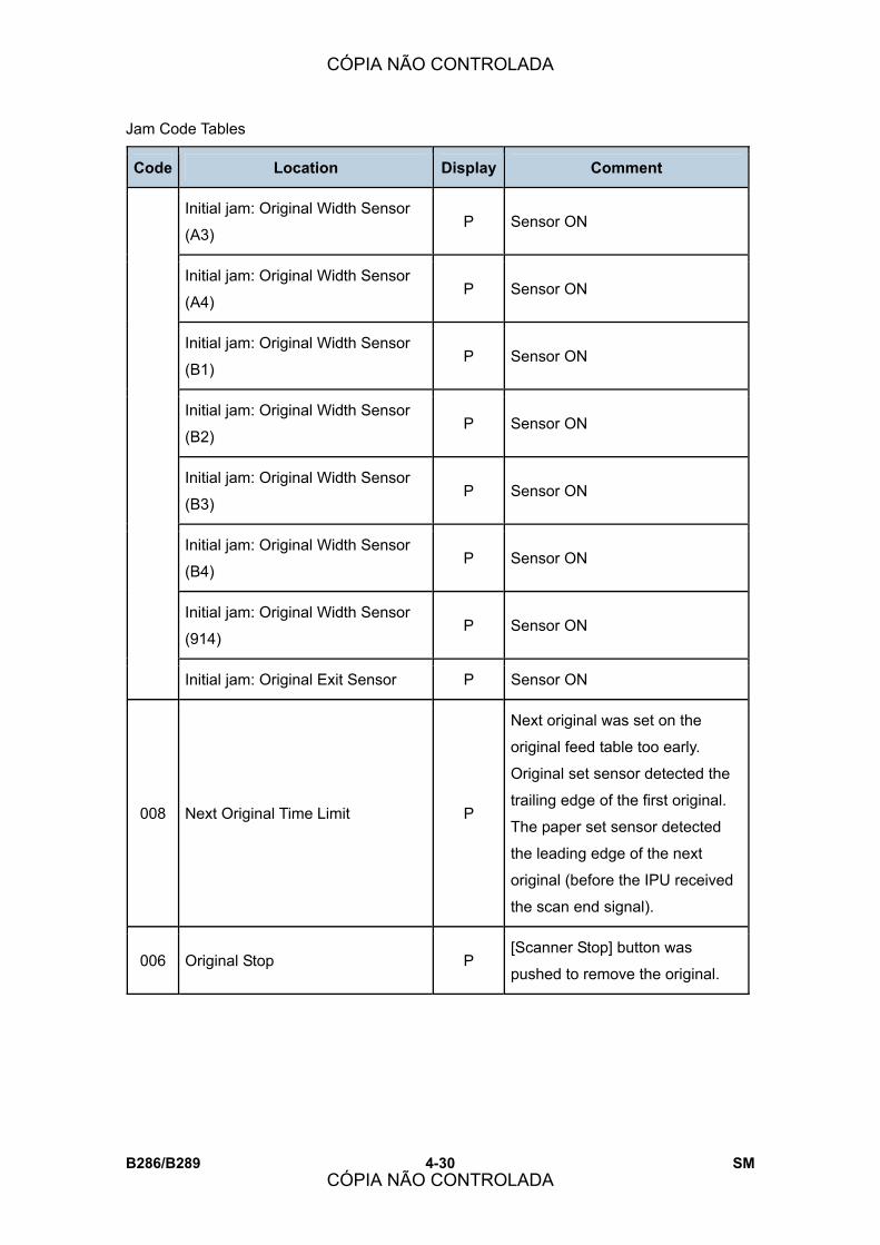
Jam Code Tables
B286/B289 4-30 SM
Code Location Display Comment
Initial jam: Original Width Sensor
(A3) P Sensor ON
Initial jam: Original Width Sensor
(A4) P Sensor ON
Initial jam: Original Width Sensor
(B1) P Sensor ON
Initial jam: Original Width Sensor
(B2) P Sensor ON
Initial jam: Original Width Sensor
(B3) P Sensor ON
Initial jam: Original Width Sensor
(B4) P Sensor ON
Initial jam: Original Width Sensor
(914) P Sensor ON
Initial jam: Original Exit Sensor P Sensor ON
008 Next Original Time Limit P
Next original was set on the
original feed table too early.
Original set sensor detected the
trailing edge of the first original.
The paper set sensor detected
the leading edge of the next
original (before the IPU received
the scan end signal).
006 Original Stop P [Scanner Stop] button was
pushed to remove the original.
CÓPIA NÃO CONTROLADA
CÓPIA NÃO CONTROLADA

Jam Code Tables
SM 4-31 B286/B289
Trou
ble-
sh
ootin
g
Scanner Late Jams
Code Location Display Comment
002 Registration Jam P Registration sensor not ON
003 Registration Jam P Registration sensor OFF
007 Exit Jam P Fusing exit sensor not ON
Scanner Lag Jams
Code Location Display Comment
004 Registration Jam (Sensor not OFF) P
005 Registration Jam P
4.3.3 PLOTTER (PRINTER) JAMS
Plotter Standby Jams
Code Location Display Comment
001 Initial Jam: Registration Sensor B
Initial Jam: Paper Set Sensor B
Initial Jam: Fusing Exit Sensor C
CÓPIA NÃO CONTROLADA
CÓPIA NÃO CONTROLADA

Jam Code Tables
B286/B289 4-32 SM
Plotter Late Jams
Code Location Display Comment
003 Roll 1 Non-Feed Jam A2
004 Roll 2 Non-Feed Jam A2
005 Paper cassette Non-Feed Jam A1
008 Roll Feeder Exit Jam A1 RF exit sensor not ON
013 Registration Jam B Registration sensor not ON
016 Fusing Exit Jam C Fusing exit sensor not ON.
034 Bypass Non-Feed B Paper set not ON.
Plotter Lag Jams
Code Location Display Comment
053 Roll 1 Feed Lag A2 Roll paper failed to feed
054 Roll 2 Feed Lag A2 Roll paper failed to feed
055 Paper Cassette Lag A1 Cut sheets failed to feed
058 Roll Feeder Exit Jam A2 RF exit sensor failed to go OFF
063 Registration Jam B Paper registration sensor failed to go
OFF.
066 Fusing Exit Jam C Fusing exit sensor failed to go OFF.
084 Bypass Jam B Paper set sensor failed to go OFF.
CÓPIA NÃO CONTROLADA
CÓPIA NÃO CONTROLADA

Jam Code Tables
SM 4-33 B286/B289
Trou
ble-
sh
ootin
g
4.3.4 FOLDER UNIT JAMS
Folder Unit Standby Jams
Code Location Display Comment
Initial Jam: Folder Entrance N1 Folder entrance sensor
Initial Jam: Relay Sensor N5 Relay sensor 1
Initial Jam: Fan Folder
Entrance N7 Fan folder entrance sensor
Initial Jam: Fan Folding (Front) N7 Fan fold LED (F1), fan fold sensor
(F2) pair
Initial Jam: Fan Folding (Rear) N7 Fan fold LED (R1), fan fold sensor
(R2) pair
Initial Jam: Folder Unit Exit N7 Folder unit exit sensor
Initial Jam: Straight-Through
Exit N3 Straight-Through Sensor
Initial Jam: Manual Feeder
Entrance V1 Bypass Entrance Sensor
Initial Jam: Folder Unit
Entrance (from Manual Feed
unit)
V2 Bypass Relay Sensor
Initial Jam: Bypass Entrance V1 Paper Width Sensor (880)
Initial Jam: Bypass Entrance V1 Paper Width Sensor (841)
Initial Jam: Bypass Entrance V1 Paper Width Sensor (594)
Initial Jam: Bypass Entrance V1 Paper Width Sensor (420)
Initial Jam: Bypass Entrance V1 Paper Width Sensor (297)
Initial Jam: Bypass Entrance V1 Paper Width Sensor (30 in.)
100
Initial Jam: Bypass Entrance V1 Paper Width Sensor (B4)
CÓPIA NÃO CONTROLADA
CÓPIA NÃO CONTROLADA
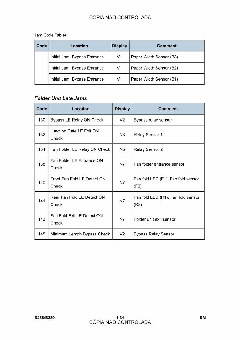
Jam Code Tables
B286/B289 4-34 SM
Code Location Display Comment
Initial Jam: Bypass Entrance V1 Paper Width Sensor (B3)
Initial Jam: Bypass Entrance V1 Paper Width Sensor (B2)
Initial Jam: Bypass Entrance V1 Paper Width Sensor (B1)
Folder Unit Late Jams
Code Location Display Comment
130 Bypass LE Relay ON Check V2 Bypass relay sensor
132 Junction Gate LE Exit ON
Check N3 Relay Sensor 1
134 Fan Folder LE Relay ON Check N5 Relay Sensor 2
138 Fan Folder LE Entrance ON
Check N7 Fan folder entrance sensor
140 Front Fan Fold LE Detect ON
Check N7
Fan fold LED (F1), Fan fold sensor
(F2)
141 Rear Fan Fold LE Detect ON
Check N7
Fan fold LED (R1), Fan fold sensor
(R2)
143 Fan Fold Exit LE Detect ON
Check N7 Folder unit exit sensor
145 Minimum Length Bypass Check V2 Bypass Relay Sensor
CÓPIA NÃO CONTROLADA
CÓPIA NÃO CONTROLADA

Jam Code Tables
SM 4-35 B286/B289
Trou
ble-
sh
ootin
g
Folder Unit Lag Jams
Code Location Display Comment
131 Bypass TE Relay OFF Check V2 Bypass relay sensor
133 Junction Gate TE Exit OFF
Check N3 Relay Sensor 1
135 Fan Folder TE Relay OFF
Check N5 Relay Sensor 2
139 Fan Folder TE Entrance OFF
Check N7 Fan folder entrance sensor
142 Rear Fan Fold TE Detect OFF
Check N7
Fan fold LED (R1), Fan fold sensor
(R2)
144 Fan Fold Exit TE Detect OFF
Check N7 Folder unit exit sensor
146 Fold Count Limit N7 Front/Rear Fold Sensor Pairs
CÓPIA NÃO CONTROLADA
CÓPIA NÃO CONTROLADA
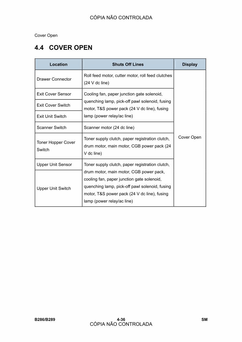
Cover Open
B286/B289 4-36 SM
4.4 COVER OPEN
Location Shuts Off Lines Display
Drawer Connector Roll feed motor, cutter motor, roll feed clutches
(24 V dc line)
Exit Cover Sensor
Exit Cover Switch
Exit Unit Switch
Cooling fan, paper junction gate solenoid,
quenching lamp, pick-off pawl solenoid, fusing
motor, T&S power pack (24 V dc line), fusing
lamp (power relay/ac line)
Scanner Switch Scanner motor (24 dc line)
Toner Hopper Cover
Switch
Toner supply clutch, paper registration clutch,
drum motor, main motor, CGB power pack (24
V dc line)
Upper Unit Sensor
Upper Unit Switch
Toner supply clutch, paper registration clutch,
drum motor, main motor, CGB power pack,
cooling fan, paper junction gate solenoid,
quenching lamp, pick-off pawl solenoid, fusing
motor, T&S power pack (24 V dc line), fusing
lamp (power relay/ac line)
Cover Open
CÓPIA NÃO CONTROLADA
CÓPIA NÃO CONTROLADA

Fuses
SM 4-37 B286/B289
Trou
ble-
sh
ootin
g
4.5 FUSES
The fuses differ slightly with geographic location.
Main Machine Fuse Table
No. No. Area Part No. Specification
120V 11071079 15A 125 Vac/250 Vac CP101
220 - 240V 11070957 8A 125 Vac/250 Vac
120V 11070629 15A 125 Vac FU001
220 - 240V 11071054 T6.3AH 250 Vac
FU002 120V, 220 - 240V 11071095 T2A 250 Vac
120V 11070016 T10AH 250 Vac FU101
220 - 240V 11071054 T6.3AH 250 Vac
FU301 11071067 T6.3AL 250 Vac
FU302 11071067 T6.3AL 250 Vac
PSU
FU303
120V, 220 - 240V
11071067 T6.3AL 250 Vac
RFDB FU501 120V, 220 - 240V T 2A 250 V
SFDB FU601 120V, 220 - 240V T1 A/250 V
⇒
Rev. 10/2007
CÓPIA NÃO CONTROLADA
CÓPIA NÃO CONTROLADA
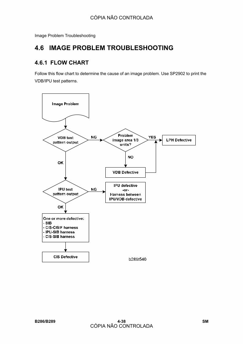
Image Problem Troubleshooting
B286/B289 4-38 SM
4.6 IMAGE PROBLEM TROUBLESHOOTING
4.6.1 FLOW CHART
Follow this flow chart to determine the cause of an image problem. Use SP2902 to print the
VDB/IPU test patterns.
CÓPIA NÃO CONTROLADA
CÓPIA NÃO CONTROLADA

Image Problem Troubleshooting
SM 4-39 B286/B289
Trou
ble-
sh
ootin
g
4.6.2 SCANNING
1. No image (or no image with only vertical black lines on the output)
Possible causes:
! Connection problem between CIS and IPU.
! CIS defective
2. No image (solid black copy/print, or no image with only vertical white lines on the output)
Possible causes:
! Connection problem between CIS and IPU.
! CIS defective
3. Light image
Possible causes:
! Low CIS output
! IPU board defective
CÓPIA NÃO CONTROLADA
CÓPIA NÃO CONTROLADA

Image Problem Troubleshooting
B286/B289 4-40 SM
4. Vertical black lines
Possible causes:
! Dirty exposure glass
! CIS defective
5. Vertical white lines
Possible causes:
! Dirty exposure glass
! Dirt or scratches on the white plate above the CIS
! CIS defective
6. Black or white bands with no image-width 1/8 A0 (E) size
Possible causes:
! Connection problem between CIS and IPU
! CIS output error
! IPU board adjustment error
CÓPIA NÃO CONTROLADA
CÓPIA NÃO CONTROLADA
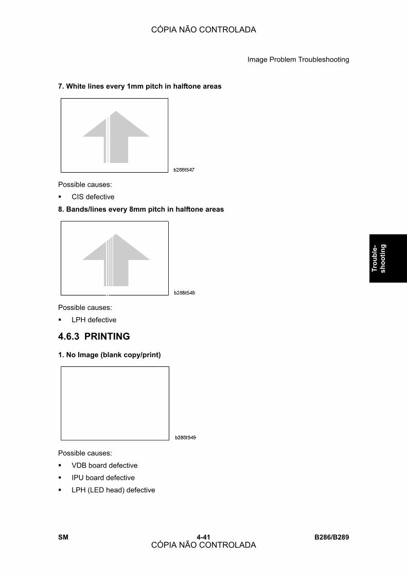
Image Problem Troubleshooting
SM 4-41 B286/B289
Trou
ble-
sh
ootin
g
7. White lines every 1mm pitch in halftone areas
Possible causes:
! CIS defective
8. Bands/lines every 8mm pitch in halftone areas
Possible causes:
! LPH defective
4.6.3 PRINTING
1. No Image (blank copy/print)
Possible causes:
! VDB board defective
! IPU board defective
! LPH (LED head) defective
CÓPIA NÃO CONTROLADA
CÓPIA NÃO CONTROLADA

Image Problem Troubleshooting
B286/B289 4-42 SM
2. Band with no image-width 1/3 of image
Possible causes:
! Connection problem between VDB and LPH
! LPH head defective
3. Bands with no image-width 1/8 A0 (E) size
Possible causes:
! VDB board defective
4. Vertical white and black line at 150 mm from center.
Possible causes:
! LPH Joints adjustment error
CÓPIA NÃO CONTROLADA
CÓPIA NÃO CONTROLADA

Image Problem Troubleshooting
SM 4-43 B286/B289
Trou
ble-
sh
ootin
g
5. Horizontal line broken at 150 mm from center.
Possible causes:
! LPH subscan timing error at joint position
4.6.4 DENSITY CHANGES AT CIS JOINTS
Case 1: Dark image density at CIS1, CIS3, and CIS5.
Possible causes:
! The main machine is installed near a window. Direct sunlight is hitting the CIS units
inside the scanner unit.
Case 2: Dark image density at CIS2 and CIS4.
Possible causes:
! The white plate is not flat against the original.
CÓPIA NÃO CONTROLADA
CÓPIA NÃO CONTROLADA

Image Problem Troubleshooting
B286/B289 4-44 SM
4.6.5 OTHER PROBLEMS
1. Excessive curl Possible causes:
! When a paper roll reaches its end, the paper closest to the core tends to have
excessive curl.
! There is no way to correct this. Operators should be instructed to use cut sheets if
possible.
2. Shrinkage of areas in incomplete images
Possible causes:
! Some customers complained about loss of borderlines at the trailing edge of copies
when an A1 original is reduced to A3.
! This problem has not been corrected.
CÓPIA NÃO CONTROLADA
CÓPIA NÃO CONTROLADA

Board LEDS
SM 4-45 B286/B289
Trou
ble-
sh
ootin
g
4.7 BOARD LEDS
This section describes the functions of the LEDs on the most important PCBs.
4.7.1 PSU, MCU, IPU
PSU LEDs The PSU supplies dc current to electrical components and also controls the flow of ac
current to the fusing lamp, dehumidifiers (x4), and anti-condensation heaters (x2).
No. Color Meaning
ON Normal
Vaa +24 V GREEN OFF
! PSU defective, or the +24 V system has shorted or
is defective.
ON Normal
Vca2 �12 V GREEN OFF
! PSU defective, or the �12 V system has shorted or
is defective.
ON Normal
Vca2 +12 V GREEN OFF
! PSU defective, or the +12 V system (HDD) has
shorted or is defective.
ON Normal Vcc +5.1 V GREEN
OFF ! PSU defective, or the +5.1 system (Vcc2) has
CÓPIA NÃO CONTROLADA
CÓPIA NÃO CONTROLADA
Board LEDS
B286/B289 4-46 SM
No. Color Meaning
shorted or is defective.
ON Normal. Also remains on in auto off mode.
Vcc1 +5.1 V GREEN OFF
! PSU defective, or the +5.1 system (Vcc1) has
shorted or is defective.
MCU LEDs The MCU (Main Control Unit) performs system control, base engine control, scanner
control, and also controls the IPU. The MCU also controls:
! I/O for the base engine (high voltage power supply, motors, sensors, solenoids,
clutches, fusing temperature, customer support systems, etc.)
! Scanning signals (sensors, motors)
! Power supply
! Scanner motor output
MCU LED 1 to 4
No. Color Operation LED Action
Firmware update Flashes rapidly LED 1 GREEN
End of firmware update, normal operation Flashes slowly
Firmware update On LED 2 GREEN
End of firmware update, normal operation Off
Firmware update Flashes rapidly LED 3 ORANGE
End of firmware update, normal operation Flashes slowly
Firmware update On LED 4 ORANGE
End of firmware update, normal operation Off
CÓPIA NÃO CONTROLADA
CÓPIA NÃO CONTROLADA
Board LEDS
SM 4-47 B286/B289
Trou
ble-
sh
ootin
g
MCU DIPSW
IPU LEDs The IPU (Image Processing Unit) processes the image data. After the scan data from the
CIS has been processed, the data is sent via the VDB to the LPH for image writing.
No. Color Operation LED Action
LED 1 Green Image Processing 1 Flashes
LED 2 Green Image Processing 1 Flashes
LED 3 Green Image Processing 1 Flashes
LED 4 Green Image Processing 1 Flashes
LED 5 Green Image Processing 1 (while data is transferring) On
No. Setting
NA EU CHN
0 OFF ON ON
1 ON OFF ON
2 OFF OFF OFF
3 OFF OFF OFF
4 OFF OFF OFF
5 OFF OFF OFF
⇒Rev. 10/2007
CÓPIA NÃO CONTROLADA
CÓPIA NÃO CONTROLADA

Board LEDS
B286/B289 4-48 SM
4.7.2 SIB, VDB
VDB LEDs The VDB (Video Drive Board) controls the LPH (LED Print Head). The VDB receives the
image processed data from the IPU and sends it to the LPH.
No. Color Operation LED Action
LED 100 GREEN Timer Flashes
LED 101 YELLOW During image writing (RFGATE signal) ON
LED 102 GREEN Outputting LPH 2 print data (1-bit) ON
LED 103 YELLOW Outputting ID sensor sampling ON
LED 104 GREEN Calibrating amount of LPH light ON
CÓPIA NÃO CONTROLADA
CÓPIA NÃO CONTROLADA

Board LEDS
SM 4-49 B286/B289
Trou
ble-
sh
ootin
g
SIB LEDs The SIB (Scanner Interface Board) controls and processes the analog-to-digital (AD)
conversion of the image scanned with the CIS.
No. Color Operation LED Action
LED 1 RED Confirming that the control circuits on the
SIB are operating normally. Flashes
GW Controller Board The controller board interfaces with the IPU and accesses all the expansion applications
provided on boards and SD cards installed in the slots of the controller board.
Controller Board LEDs
No. Color Operation LED Action
Normal operation Off
During firmware update Alternates flashes with LED 2 LED 1 RED
At completion of firmware
update On
Normal operation Flashes
During firmware update Alternates flashes with LED 1 LED 2 RED
At completion of firmware
update On
CÓPIA NÃO CONTROLADA
CÓPIA NÃO CONTROLADA

Board LEDS
B286/B289 4-50 SM
Controller Board DIP SW3
Bit Application Setting
0 Boot mode selection On: FlashROM (Default)
Off: SD Card
1 Not Used ---
2 Not Used ---
3 Not Used ---
4 Not Used ---
5 Not Used ---
6 Not Used ---
7 HDD Power Control On: HDD OFF in CTL_OFF mode (Default)
Off: HDD ON in CTL_OFF mode
CÓPIA NÃO CONTROLADA
CÓPIA NÃO CONTROLADA
SERVICE TABLES
CÓPIA NÃO CONTROLADA
CÓPIA NÃO CONTROLADA

CÓPIA NÃO CONTROLADA
CÓPIA NÃO CONTROLADA

Using the SP Mode
SM 5-1 B286/B289
Serv
ice
Tabl
es
5. SERVICE TABLES
5.1 USING THE SP MODE
5.1.1 DIRECT ENTRY
Normal Direct Entry 1. Go into the SP mode.
! Push [Clear] (").
! Push [1] [0] [7].
! Push and hold [Clear/Stop] (#) for 3 seconds.
The initial SP mode screen appears.
2. Touch �Copy SP.�
3. When the SP mode is opened it is in direct entry mode (SP Direct). Input the full
number of the SP code. Then push [#].
When you input the number:
! Do not input a hyphen (-) between the first 4 digits and the last 3 digits.
! If the 2nd half of the SP code is only 1 or 2 digits, input the zeros that are in front.
For example, if the 2nd number is 1 or 12, push [0] [0] [0] or [0] [1] [2].
! If you input only the first 4 digits of an SP that has sub levels, the first SP code
(001) will be shown. Push the key below �PrevMenu� or �NextMenu� to show the
SP. Then push the key below �Set� or push [#].
4. Set the adjustment value.
! If a minus sign (-) is necessary, push ( to change the +/- sign.
! If a decimal point is necessary, do not push the decimal point button. For example,
CÓPIA NÃO CONTROLADA
CÓPIA NÃO CONTROLADA

Using the SP Mode
B286/B289 5-2 SM
to input �-1.3�, push ( for the minus sign, then push [1] [3].
! If you make an error, push # to reset the setting, then try again. You cannot
correct it with a new entry.
5. Push the key below �Set� on the LCD, or push [#] to enable the setting you have just
input.
6. To go out of SP mode, push the key on the operation panel below �Exit� one or more
times until you see the initial copy screen.
7. Switch the main power switch off. Then switch it on again.
! You must switch the main power switch off then on again to enable the SP codes
that you have just input.
Rapid Direct Entry 1. Refer to the �Service Tables� in this section to find the SP code.
2. Go into the SP mode.
! Push [Clear] (").
! Push [1] [0] [7].
! Push and hold [Clear/Stop] (#) for 3 seconds.
3. Input the group number. Then input the full number to go directly to the SP code
screen. It is not necessary to stop until the screens show.
Examples
[1] (Copy) [2001002] Shows the setting screen for SP2001-2.
[1] (Copy) [2001]
Shows the setting screen for the first level below
SP2001 (1).
Note: To see the level before or after, push �PrevMenu�
or �NextMenu.� With SP2001-xxx on the display, input
the full number again to go directly to 2001-2.
CÓPIA NÃO CONTROLADA
CÓPIA NÃO CONTROLADA
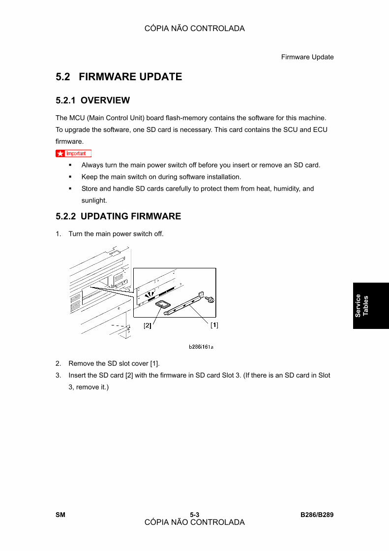
Firmware Update
SM 5-3 B286/B289
Serv
ice
Tabl
es
5.2 FIRMWARE UPDATE
5.2.1 OVERVIEW
The MCU (Main Control Unit) board flash-memory contains the software for this machine.
To upgrade the software, one SD card is necessary. This card contains the SCU and ECU
firmware.
! Always turn the main power switch off before you insert or remove an SD card.
! Keep the main switch on during software installation.
! Store and handle SD cards carefully to protect them from heat, humidity, and
sunlight.
5.2.2 UPDATING FIRMWARE
1. Turn the main power switch off.
2. Remove the SD slot cover [1].
3. Insert the SD card [2] with the firmware in SD card Slot 3. (If there is an SD card in Slot
3, remove it.)
CÓPIA NÃO CONTROLADA
CÓPIA NÃO CONTROLADA
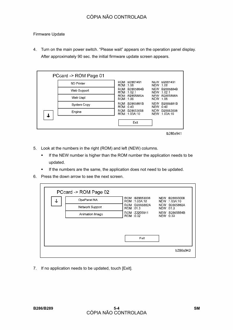
Firmware Update
B286/B289 5-4 SM
4. Turn on the main power switch. �Please wait� appears on the operation panel display.
After approximately 90 sec. the initial firmware update screen appears.
5. Look at the numbers in the right (ROM) and left (NEW) columns.
! If the NEW number is higher than the ROM number the application needs to be
updated.
! If the numbers are the same, the application does not need to be updated.
6. Press the down arrow to see the next screen.
7. If no application needs to be updated, touch [Exit].
CÓPIA NÃO CONTROLADA
CÓPIA NÃO CONTROLADA
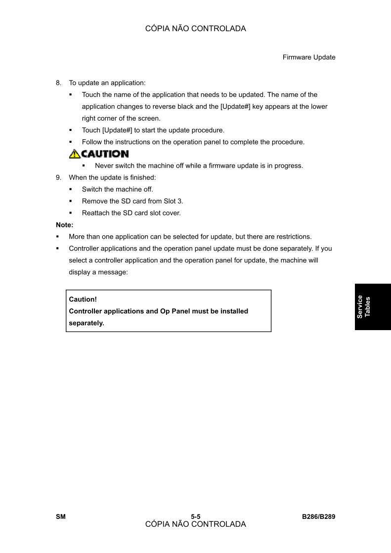
Firmware Update
SM 5-5 B286/B289
Serv
ice
Tabl
es
8. To update an application:
! Touch the name of the application that needs to be updated. The name of the
application changes to reverse black and the [Update#] key appears at the lower
right corner of the screen.
! Touch [Update#] to start the update procedure.
! Follow the instructions on the operation panel to complete the procedure.
! Never switch the machine off while a firmware update is in progress.
9. When the update is finished:
! Switch the machine off.
! Remove the SD card from Slot 3.
! Reattach the SD card slot cover.
Note: ! More than one application can be selected for update, but there are restrictions.
! Controller applications and the operation panel update must be done separately. If you
select a controller application and the operation panel for update, the machine will
display a message:
Caution! Controller applications and Op Panel must be installed separately.
CÓPIA NÃO CONTROLADA
CÓPIA NÃO CONTROLADA
User Tools
B286/B289 5-6 SM
5.3 USER TOOLS
5.3.1 USER TOOL SUMMARY
Push [User Tools].
System Settings
Tab Item
General Features Program/Change/Delete User Text
Panel Key Sound On/Off
Warm Up Beeper On/Off
Copy Count Display Up/Down
Function Priority Copier, Document Server
Print Priority
Display Mode,
Copier/Document Server,
Interleave, Job Order
Function Reset Timer Set Time
Interleave Printing Enter the number of sheets�
Original Feed Delay 1 1 sec.
Original Feed Delay 2 1 sec.
CÓPIA NÃO CONTROLADA
CÓPIA NÃO CONTROLADA
User Tools
SM 5-7 B286/B289
Serv
ice
Tabl
es
Tab Item
Feed Start Method Auto, Press Start Key
' Next Fine Ratio Adjustment: Copier Plain Paper, Recycled Paper,
Translucent Paper, Film
Adjust Scan Position NG
System Status/Job List Display Time Enter the time�
Key Repeat Off, Normal, Repeat Time:
Medium, Repeat Time: Long
Tray Paper
Settings Paper Tray Priority: Copier Tray 1, Tray 2, Tray 3
Tray Paper Size: Tray 1 Engineering, Architecture,
Others
Tray Paper Size: Tray 2 Engineering, Architecture,
Others
Tray Paper Size: Tray 3 Engineering, Architecture,
Others
'Next Paper Type: Paper Bypass
Paper Type: Tray 1
Paper Type: Tray 2
No Display, Recycled Paper,
Translucent Paper
Paper Type: Tray 3 No Display, Recycled Paper
Paper Thickness: Paper Tray
Paper Thickness: Paper Bypass
CÓPIA NÃO CONTROLADA
CÓPIA NÃO CONTROLADA

User Tools
B286/B289 5-8 SM
Paper Volume Paper Roll 1, Paper
Roll 2
Timer Settings Auto Off Timer
Energy Saver Timer
Panel Off Timer
System Auto Reset Timer
Copier/Document Server Auto Reset Timer
Enter the time�
Set Date Enter the date�
Set Time
Auto Logout Timer Enter the time�
Administrator
Tools Address Book Management
Address Book: Program/Change/Delete
Group
Address Book: Change Order
Address Book: Edit Title
Address Book: Switch Title
Back Up/Restore Address Book
Display/Print Counter
See �Operating
Instructions�
CÓPIA NÃO CONTROLADA
CÓPIA NÃO CONTROLADA

User Tools
SM 5-9 B286/B289
Serv
ice
Tabl
es
Display/Print Counter per User
'Next User Authentication Management
Administrator Authentication Management
Program/Change Administrator
Key Counter Management
External Charge Unit Management
Enhanced External Charge Unit
Management
Extended Security
Auto Delete File in Document Server
See �Operating
Instructions�
Copier/Document Server Features
Tab Item
General Features Auto Image Density Priority
Copy Quality
CÓPIA NÃO CONTROLADA
CÓPIA NÃO CONTROLADA
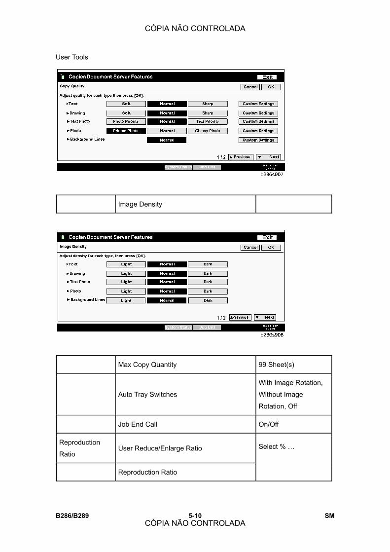
User Tools
B286/B289 5-10 SM
Image Density
Max Copy Quantity 99 Sheet(s)
Auto Tray Switches
With Image Rotation,
Without Image
Rotation, Off
Job End Call On/Off
Reproduction
Ratio User Reduce/Enlarge Ratio
Reproduction Ratio
Select % �
CÓPIA NÃO CONTROLADA
CÓPIA NÃO CONTROLADA

User Tools
SM 5-11 B286/B289
Serv
ice
Tabl
es
Reduce/Enlarge Ratio Priority
Magnification Key Display Engineering,
Architecture
Edit Adjust Position
Erase Border Width
Erase Original Shadow in Combine
Image Repeat Separation Line
Double Copies Separation Line
Separation Line in Combine
Copy Order in Combine
Program/Delete Format
Margin Adjustment Priority
Partial Copy Size
See �Operating
Instructions�
Stamp Background Numbering
Preset Stamp
User Stamp
Date Stamp
Page Numbering
See �Operating
Instructions�
CÓPIA NÃO CONTROLADA
CÓPIA NÃO CONTROLADA

User Tools
B286/B289 5-12 SM
Input/Output Rotate Sort: Auto Paper Continue See �Operating
Instructions�
Administrator
Tools
Menu Protect See �Operating
Instructions�
Espanol
Espanol English
Inquiry
Counter
) Total Counter [ 11] Meters
[Print Counter List]
CÓPIA NÃO CONTROLADA
CÓPIA NÃO CONTROLADA

Input Check
SM 5-13 B286/B289
Serv
ice
Tabl
es
5.4 INPUT CHECK
You can check the sensors and switches with SP5803. Go into one of the modes in the
tables.
In each mode, the display shows an 8-digit number. The digits are given numbers 7 to 0
from left to right. Each bit shows the on/off condition of a sensor or switch with a 0 or 1. For
example:
Display 1 1 0 0 0 0 1 0
Bit 7 6 5 4 3 2 1 0
1 Roll Tray Input Status
bit-7 Not used
bit-6 Not used
bit-5 Not used
bit-4 Cassette Set Sensor 0: Close 1: Open
bit-3 Cutter HP switch � Left 0: At HP 1: Not at HP.
bit-2 Cutter HP switch � Right 0: At HP 1: Not at HP
bit-1 Not used
bit-0 Upper Unit 0: Close 1: Open
2 1st & 2nd Roll Input Status
bit-7 Not used
bit-6 Roll End Sensor 2 0: Paper present 1: Paper out
bit-5 Not used
bit-4 Roll End Sensor 4 (EXP) 0: No paper 1: Paper present
bit-3 Not used
CÓPIA NÃO CONTROLADA
CÓPIA NÃO CONTROLADA
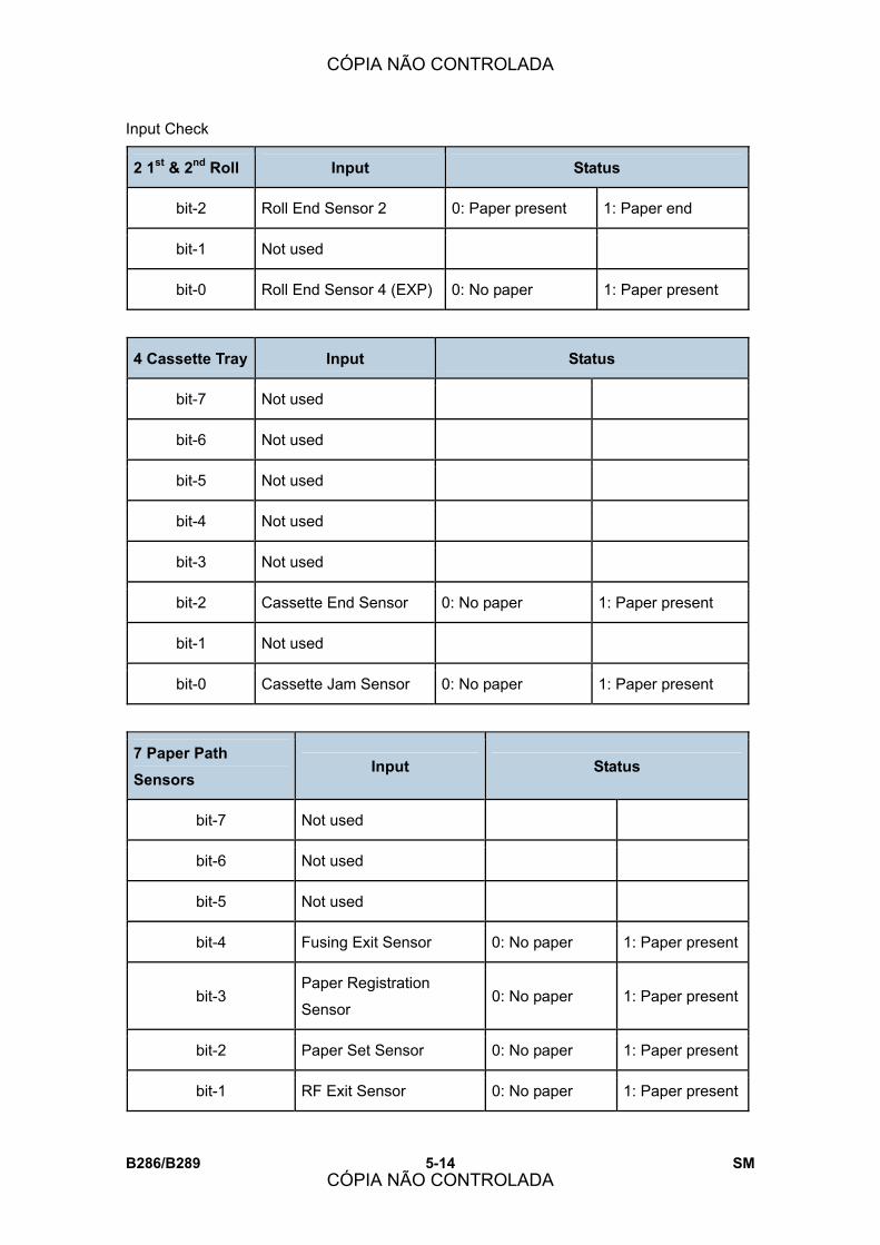
Input Check
B286/B289 5-14 SM
2 1st & 2nd Roll Input Status
bit-2 Roll End Sensor 2 0: Paper present 1: Paper end
bit-1 Not used
bit-0 Roll End Sensor 4 (EXP) 0: No paper 1: Paper present
4 Cassette Tray Input Status
bit-7 Not used
bit-6 Not used
bit-5 Not used
bit-4 Not used
bit-3 Not used
bit-2 Cassette End Sensor 0: No paper 1: Paper present
bit-1 Not used
bit-0 Cassette Jam Sensor 0: No paper 1: Paper present
7 Paper Path Sensors
Input Status
bit-7 Not used
bit-6 Not used
bit-5 Not used
bit-4 Fusing Exit Sensor 0: No paper 1: Paper present
bit-3 Paper Registration
Sensor 0: No paper 1: Paper present
bit-2 Paper Set Sensor 0: No paper 1: Paper present
bit-1 RF Exit Sensor 0: No paper 1: Paper present
CÓPIA NÃO CONTROLADA
CÓPIA NÃO CONTROLADA
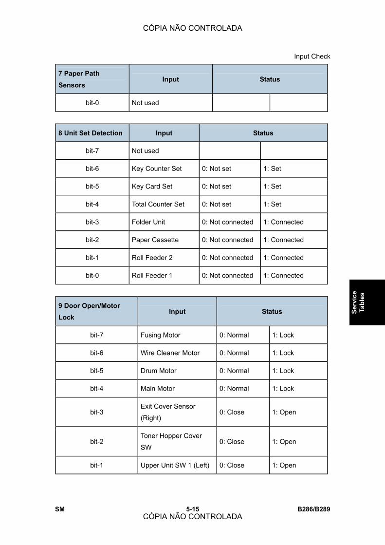
Input Check
SM 5-15 B286/B289
Serv
ice
Tabl
es
7 Paper Path Sensors
Input Status
bit-0 Not used
8 Unit Set Detection Input Status
bit-7 Not used
bit-6 Key Counter Set 0: Not set 1: Set
bit-5 Key Card Set 0: Not set 1: Set
bit-4 Total Counter Set 0: Not set 1: Set
bit-3 Folder Unit 0: Not connected 1: Connected
bit-2 Paper Cassette 0: Not connected 1: Connected
bit-1 Roll Feeder 2 0: Not connected 1: Connected
bit-0 Roll Feeder 1 0: Not connected 1: Connected
9 Door Open/Motor Lock
Input Status
bit-7 Fusing Motor 0: Normal 1: Lock
bit-6 Wire Cleaner Motor 0: Normal 1: Lock
bit-5 Drum Motor 0: Normal 1: Lock
bit-4 Main Motor 0: Normal 1: Lock
bit-3 Exit Cover Sensor
(Right) 0: Close 1: Open
bit-2 Toner Hopper Cover
SW 0: Close 1: Open
bit-1 Upper Unit SW 1 (Left) 0: Close 1: Open
CÓPIA NÃO CONTROLADA
CÓPIA NÃO CONTROLADA
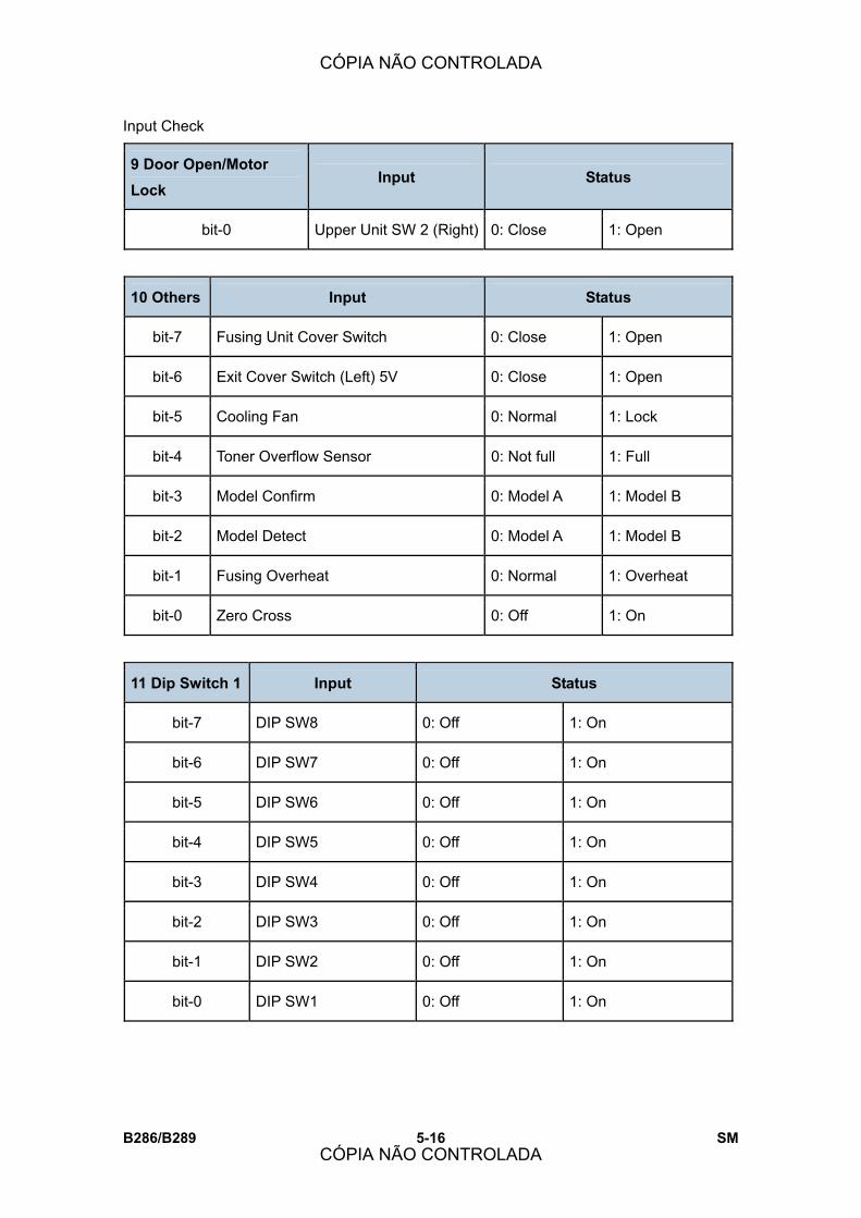
Input Check
B286/B289 5-16 SM
9 Door Open/Motor Lock
Input Status
bit-0 Upper Unit SW 2 (Right) 0: Close 1: Open
10 Others Input Status
bit-7 Fusing Unit Cover Switch 0: Close 1: Open
bit-6 Exit Cover Switch (Left) 5V 0: Close 1: Open
bit-5 Cooling Fan 0: Normal 1: Lock
bit-4 Toner Overflow Sensor 0: Not full 1: Full
bit-3 Model Confirm 0: Model A 1: Model B
bit-2 Model Detect 0: Model A 1: Model B
bit-1 Fusing Overheat 0: Normal 1: Overheat
bit-0 Zero Cross 0: Off 1: On
11 Dip Switch 1 Input Status
bit-7 DIP SW8 0: Off 1: On
bit-6 DIP SW7 0: Off 1: On
bit-5 DIP SW6 0: Off 1: On
bit-4 DIP SW5 0: Off 1: On
bit-3 DIP SW4 0: Off 1: On
bit-2 DIP SW3 0: Off 1: On
bit-1 DIP SW2 0: Off 1: On
bit-0 DIP SW1 0: Off 1: On
CÓPIA NÃO CONTROLADA
CÓPIA NÃO CONTROLADA

Input Check
SM 5-17 B286/B289
Serv
ice
Tabl
es
12 Original Size Sensor 1
Input Status
bit-7 Not used
bit-6 Original Width Sensor A1
(22�) 0: No paper
1: Paper
present
bit-5 Original Width Sensor B2
(18�) 0: No paper
1: Paper
present
bit-4 Original Width Sensor A2
(17�) 0: No paper
1: Paper
present
bit-3 Original Width Sensor B3
(12�) 0: No paper
1: Paper
present
bit-2 Original Width Sensor A3
(11�) 0: No paper
1: Paper
present
bit-1 Original Width Sensor B4 (9�) 0: No paper 1: Paper
present
bit-0 Original Set Sensor 0: No paper 1: Paper
present
13 Original Size Sensor 2
Input Status
bit-7 Not used
bit-6 Not used
bit-5 Not used
bit-4 Not used
bit-3 Original Width Sensor (30�) 0: No paper 1: Paper
present
bit-2 Original Width Sensor 914 0: No paper 1: Paper
CÓPIA NÃO CONTROLADA
CÓPIA NÃO CONTROLADA

Input Check
B286/B289 5-18 SM
13 Original Size Sensor 2
Input Status
(36�) present
bit-1 Original Width Sensor A0
(34�) 0: No paper
1: Paper
present
bit-0 Original Width Sensor B1
(24�) 0: No paper
1: Paper
present
14 Original Feed Unit Input Status
bit-7 Not used
bit-6 Not used
bit-5 Original Registration
Sensor 0: No paper
1: Paper
present
bit-4 Copy Exit Sensor 0: Straight-thru 1: Up
bit-3 Original Exit Sensor 0: No paper 1: Paper
present
bit-2 Scanner Stop Key 0: Normal 1: Depressed
bit-1 Scanner Switch 0: Close 1: Open
bit-0 Not used
CÓPIA NÃO CONTROLADA
CÓPIA NÃO CONTROLADA
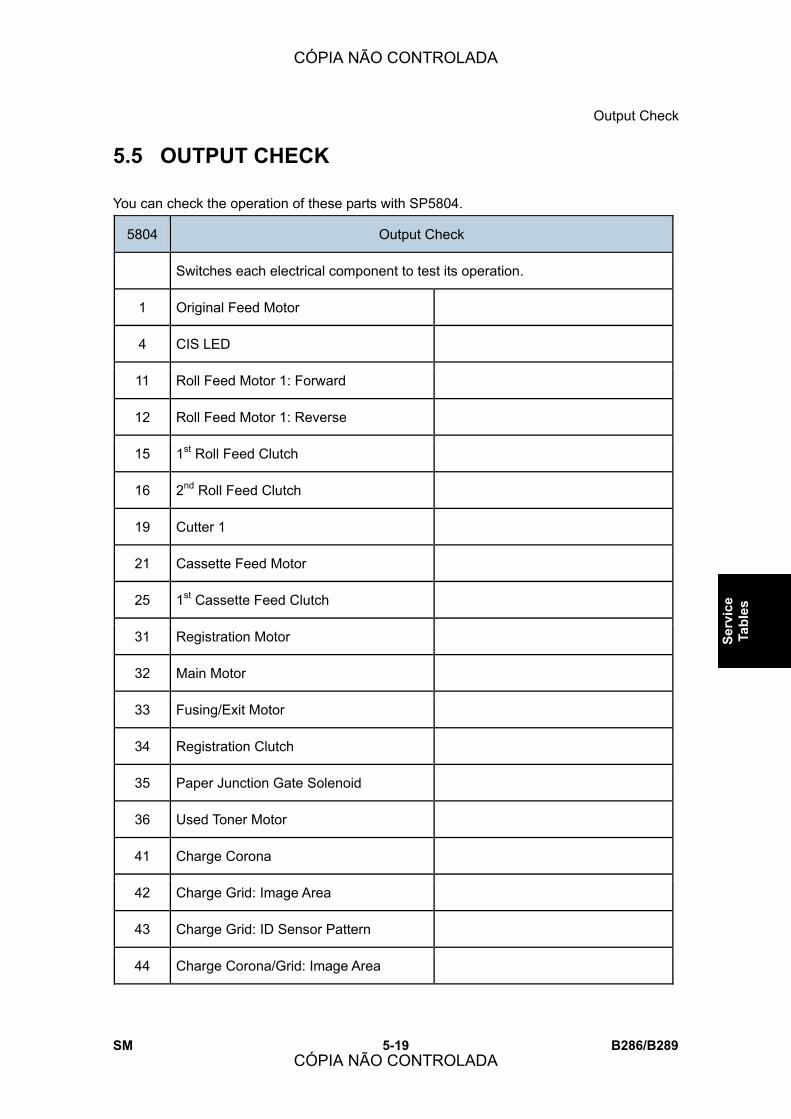
Output Check
SM 5-19 B286/B289
Serv
ice
Tabl
es
5.5 OUTPUT CHECK
You can check the operation of these parts with SP5804.
5804 Output Check
Switches each electrical component to test its operation.
1 Original Feed Motor
4 CIS LED
11 Roll Feed Motor 1: Forward
12 Roll Feed Motor 1: Reverse
15 1st Roll Feed Clutch
16 2nd Roll Feed Clutch
19 Cutter 1
21 Cassette Feed Motor
25 1st Cassette Feed Clutch
31 Registration Motor
32 Main Motor
33 Fusing/Exit Motor
34 Registration Clutch
35 Paper Junction Gate Solenoid
36 Used Toner Motor
41 Charge Corona
42 Charge Grid: Image Area
43 Charge Grid: ID Sensor Pattern
44 Charge Corona/Grid: Image Area
CÓPIA NÃO CONTROLADA
CÓPIA NÃO CONTROLADA

Output Check
B286/B289 5-20 SM
5804 Output Check
45 Development Bias: Image Area
46 Development Bias: ID Sensor Pattern
47 Transfer Corona: Leading Edge
48 Transfer Corona
49 Separation Corona: Leading Edge
50 Separation Corona
52 Toner Supply Clutch
53 Quenching Lamp
54 Pick-off Pawl Solenoid
55 ID Sensor LED
66 Charge Corona Wire Cleaner Motor
67 Recycle Counter
68 Dehumidifier
CÓPIA NÃO CONTROLADA
CÓPIA NÃO CONTROLADA
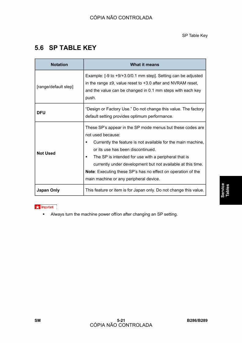
SP Table Key
SM 5-21 B286/B289
Serv
ice
Tabl
es
5.6 SP TABLE KEY
Notation What it means
[range/default step]
Example: [-9 to +9/+3.0/0.1 mm step]. Setting can be adjusted
in the range ±9, value reset to +3.0 after and NVRAM reset,
and the value can be changed in 0.1 mm steps with each key
push.
DFU �Design or Factory Use.� Do not change this value. The factory
default setting provides optimum performance.
Not Used
These SP�s appear in the SP mode menus but these codes are
not used because:
! Currently the feature is not available for the main machine,
or its use has been discontinued.
! The SP is intended for use with a peripheral that is
currently under development but not available at this time.
Note: Executing these SP�s has no effect on operation of the
main machine or any peripheral device.
Japan Only This feature or item is for Japan only. Do not change this value.
! Always turn the machine power off/on after changing an SP setting.
CÓPIA NÃO CONTROLADA
CÓPIA NÃO CONTROLADA

SP1-xxx Feed
B286/B289 5-22 SM
5.7 SP1-XXX FEED
1001 Leading Edge Registration
1 1st Roll
2 2nd Roll
3 Cassette
5 By-pass Feed
Adjusts the leading edge registration for printing. To move the
image down the page, increase the value.
[-10.0 to +10.0/ 0 /0.1 mm step]
1002 Side-to-Side Registration
1 1st Roll
2 2nd Roll
3 Cassette
5 By-pass Feed
Adjusts the side-to-side registration for printing.
[-10.0 to +10.0/ 0 /0.1 mm step]
! To move the start position to the right, increase the
value (+).
! To move the start position to the left, decrease the
value (�).
Note: If you use paper 914 mm wide, adjust within the
range of ±2 mm. If you set the adjustment outside this
range, part of the image will be cut off.
1105 Fusing Temperature Adjustment
Be sure to switch the main power switch off and on after adjustment.
1 Copy Ready Temperature
Sets the copy ready fusing temperature. The
setting is the difference from the target fusing
temperature that is set with SP1931. DFU
[0 to +20/10/1°C]
Copying can start at this temperature before
the hot roller reaches its target temperature
(SP1931).
CÓPIA NÃO CONTROLADA
CÓPIA NÃO CONTROLADA
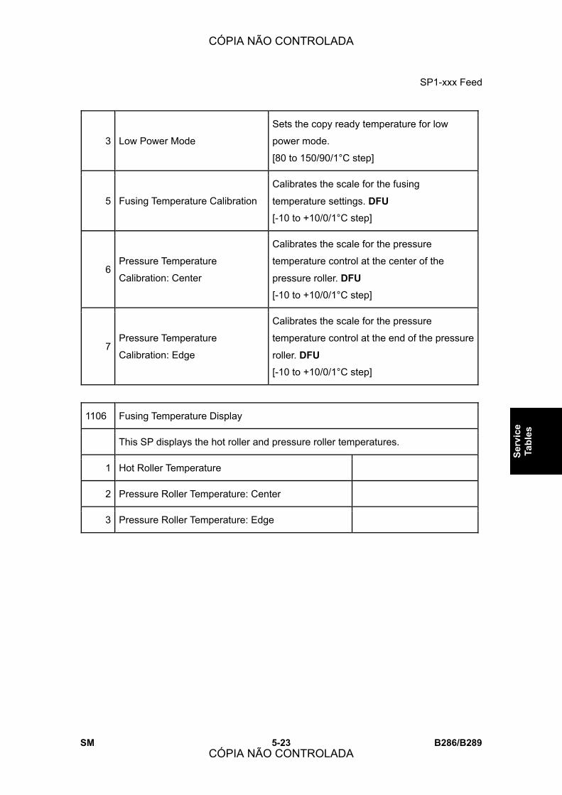
SP1-xxx Feed
SM 5-23 B286/B289
Serv
ice
Tabl
es
3 Low Power Mode
Sets the copy ready temperature for low
power mode.
[80 to 150/90/1°C step]
5 Fusing Temperature Calibration
Calibrates the scale for the fusing
temperature settings. DFU
[-10 to +10/0/1°C step]
6 Pressure Temperature
Calibration: Center
Calibrates the scale for the pressure
temperature control at the center of the
pressure roller. DFU
[-10 to +10/0/1°C step]
7 Pressure Temperature
Calibration: Edge
Calibrates the scale for the pressure
temperature control at the end of the pressure
roller. DFU
[-10 to +10/0/1°C step]
1106 Fusing Temperature Display
This SP displays the hot roller and pressure roller temperatures.
1 Hot Roller Temperature
2 Pressure Roller Temperature: Center
3 Pressure Roller Temperature: Edge
CÓPIA NÃO CONTROLADA
CÓPIA NÃO CONTROLADA

SP1-xxx Feed
B286/B289 5-24 SM
1159 Fusing Jam SC Setting
The setting of this SP determines whether the machine issues SC559 after three
successive jams occur in the fusing unit.
[0-1/0/1]
0: Disabled. SC559 not issued after 3 successive jams in the fusing unit.
1: Enabled. SC559 issued after 3 successive jams in the fusing unit. The
operator cannot restore operation of the machine by cycling the machine off/on.
SC559 is a Class �A� SC error. The service technician must restore operation of
the machine.
1801 Motor Speed Adjustment DFU
These SP�s adjust the speeds of the feed motor (paper cassette), main motor,
and fusing motor. The motor speeds can be adjusted to correct images that
appear scratchy or of uneven density. This can occur when:
! Copying originals with large quantities of black.
! Copying originals with a large quantity of black near the trailing edge.
! Printing multiple copies of positive/negative (reverse) images.
1 Feed Motor: 1st Roll DFU
[-30 to +30/0/1]
For every change of �1�, speed is adjusted 1/1635 or approximately 0.06%
Std: (70 MHz/32)/1635 = 1338 pps
Example: If the setting is changed by �+10� then:
(70 MHz/32)/(1635-10) =
(70 MHz/32)/(1625) = 1346 pps
2 Feed Motor: 2nd Roll DFU
[-30 to +30/0/1]
For every change of �1�, speed is adjusted 1/1635 or approximately 0.06%
Std: (70 MHz/32)/1635 = 1338 pps
Example: If the setting is changed by �+10� then:
(70 MHz/32)/(1635-10) =
(70 MHz/32)/(1625) = 1346 pps
CÓPIA NÃO CONTROLADA
CÓPIA NÃO CONTROLADA

SP1-xxx Feed
SM 5-25 B286/B289
Serv
ice
Tabl
es
5 Feed Motor : Cut Paper Tray DFU
[-30 to +30/0/1]
For every change of �1�, speed is adjusted 1/1063 or approximately 0.094%
Std: (19.6608 MHz/32)/1063 = 578 pps
Example: If the setting is changed by �+10� then:
(19.6608 MHz/32)/(1063-10) =
(19.6608 MHz/32)/(1053) = 583 pps
6 Main Motor DFU
[-80 to +80/0/1]
For every change of �1�, speed is adjusted 1/2485 or approximately 0.035%.
Std: (19.6608 MHz/8)/2485 = 988.07 pps
Example: If the setting changed by �+10� then:
(19.6608 MHz/8)/(2485-10) =
(19.6608 MHz/8)/(2475) = 992.9 pps
7 Fusing Motor DFU
[-100 to +100/7/1
For every change of �1�, speed is adjusted 1/1848 or approximately 0.054%.
Std: (19.6608 MHz/8)/1848 = 1329.97 pps
Example: If the setting changed by �+10� then:
(19.6608 MHz/8)/(1848-10) =
(19.6608 MHz/8)/(1838) = 1337.11 pps
1911 By-pass Feed Start Timing Adj.
Adjusts the time that the operator has to adjust the paper skew manually when
feeding paper manually from the bypass tray.
[1.0 to 8.0/2.0/0.1 sec.]
CÓPIA NÃO CONTROLADA
CÓPIA NÃO CONTROLADA
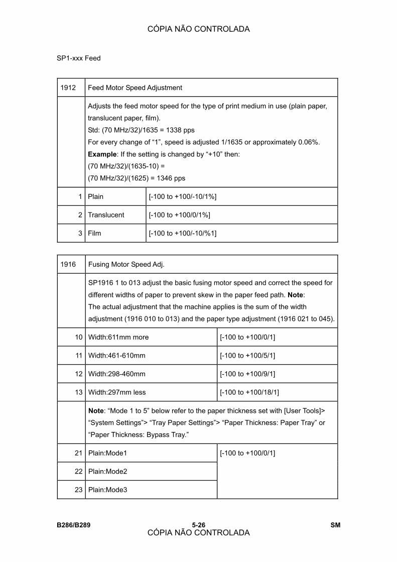
SP1-xxx Feed
B286/B289 5-26 SM
1912 Feed Motor Speed Adjustment
Adjusts the feed motor speed for the type of print medium in use (plain paper,
translucent paper, film).
Std: (70 MHz/32)/1635 = 1338 pps
For every change of �1�, speed is adjusted 1/1635 or approximately 0.06%.
Example: If the setting is changed by �+10� then:
(70 MHz/32)/(1635-10) =
(70 MHz/32)/(1625) = 1346 pps
1 Plain [-100 to +100/-10/1%]
2 Translucent [-100 to +100/0/1%]
3 Film [-100 to +100/-10/%1]
1916 Fusing Motor Speed Adj.
SP1916 1 to 013 adjust the basic fusing motor speed and correct the speed for
different widths of paper to prevent skew in the paper feed path. Note:
The actual adjustment that the machine applies is the sum of the width
adjustment (1916 010 to 013) and the paper type adjustment (1916 021 to 045).
10 Width:611mm more [-100 to +100/0/1]
11 Width:461-610mm [-100 to +100/5/1]
12 Width:298-460mm [-100 to +100/9/1]
13 Width:297mm less [-100 to +100/18/1]
Note: �Mode 1 to 5� below refer to the paper thickness set with [User Tools]>
�System Settings�> �Tray Paper Settings�> �Paper Thickness: Paper Tray� or
�Paper Thickness: Bypass Tray.�
21 Plain:Mode1
22 Plain:Mode2
23 Plain:Mode3
[-100 to +100/0/1]
CÓPIA NÃO CONTROLADA
CÓPIA NÃO CONTROLADA

SP1-xxx Feed
SM 5-27 B286/B289
Serv
ice
Tabl
es
24 Plain:Mode4
25 Plain:Mode5 [-100 to +100/25/1]
31 Trans.:Mode1
32 Trans.:Mode2
33 Trans.:Mode3
34 Trans.:Mode4
[-100 to +100/21/1]
35 Trans.:Mode5 [-100 to +100/32/1]
41 Film:Mode1
42 Film:Mode2
43 Film:Mode3
[-100 to +100/23/1]
44 Film:Mode4 [-100 to +100/41/1]
45 Film:Mode5 [-100 to +100/18/1]
Note: These comments apply to 051 to 053 below.
Changes to SP1916-51 to -53 affect the speed of the fusing motor.
(19.6608 MHz/8)/(1848) = 1329.97 pps
For every change of �1�, speed is adjusted 1/1848 = 0.054%.
Example: If the setting is changed by �+10�, then:
(19.6608 MHz/8)/(1848-10) =
(19.6608 MHz/8)/(1838) = 1337.11 pps
51 Man:420mm over [-100 to +100/0/1]
52 Man:420mm less [-100 to +100/9/1]
53 Cassette [-100 to +100/0/1]
CÓPIA NÃO CONTROLADA
CÓPIA NÃO CONTROLADA

SP1-xxx Feed
B286/B289 5-28 SM
1918 Fusing/Main Mtr Speed Change
These SP modes adjust the rate of the speed reduction between the main motor
and the fusing motor. During normal operation, the line speed in the fusing unit is
slightly faster than the line speed at registration. This keeps the paper slightly
stretched to prevent wrinkling and skewing.
However, if the speed of the drum becomes slower as a result of a change in the
amount of buckle at the registration roller, the tension on the paper will pull on the
drum and rotate it faster than the rotation of the main motor. This can cause
image distortion at the two LPH joints.
To prevent such distortion, use this SP to decrease the speed of the fusing motor.
While this lowers the line speed slightly, it also keeps the correct amount of
tension on the paper between the fusing unit and registration roller to prevent
skewing and image distortion.
Important ! There are two adjustments for each feed source and paper width: (1) �Chg
Timing� and (2) �Chg%.�
! Always do the �Chg Timing� adjustment before doing the �%Chg
adjustment.�
! The �Chg Timing� adjustment sets the length of paper to feed before the
speed reduction rate (�Chg%) takes effect.
! The �Chg%� adjustment sets the rate of speed reduction between the main
motor and fusing motor.
10 Roll/1st Chg Timing/Plain/Width > 611mm
11 Roll/1st Chg Timing/Plain/Width 461-610mm
12 Roll/1st Chg Timing/Plain/Width 298-460mm
13 Roll/1st Chg Timing/Plain/Width < 297mm
[0 to 15000/170/1mm]
15 Roll/1st Chg %/Plain/Width > 611mm
16 Roll/1st Chg %/Plain/Width 461-610mm [-9.99 to 9.99/-0.2/0.01%]
17 Roll/1st Chg %/Plain/Width 298-460mm [-9.99 to 9.99/-0.4/0.01%]
18 Roll/1st Chg %/Plain/Width < 297mm [-9.99 to 9.99/-0.5/0.01%]
CÓPIA NÃO CONTROLADA
CÓPIA NÃO CONTROLADA
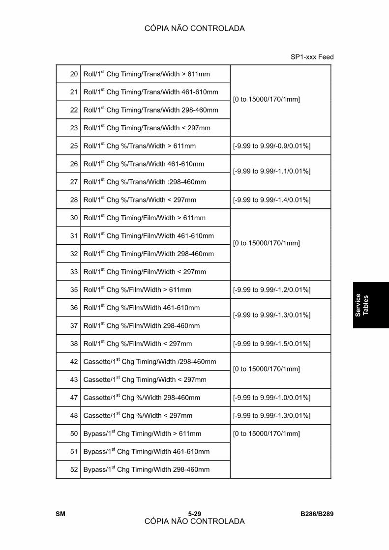
SP1-xxx Feed
SM 5-29 B286/B289
Serv
ice
Tabl
es
20 Roll/1st Chg Timing/Trans/Width > 611mm
21 Roll/1st Chg Timing/Trans/Width 461-610mm
22 Roll/1st Chg Timing/Trans/Width 298-460mm
23 Roll/1st Chg Timing/Trans/Width < 297mm
[0 to 15000/170/1mm]
25 Roll/1st Chg %/Trans/Width > 611mm [-9.99 to 9.99/-0.9/0.01%]
26 Roll/1st Chg %/Trans/Width 461-610mm
27 Roll/1st Chg %/Trans/Width :298-460mm [-9.99 to 9.99/-1.1/0.01%]
28 Roll/1st Chg %/Trans/Width < 297mm [-9.99 to 9.99/-1.4/0.01%]
30 Roll/1st Chg Timing/Film/Width > 611mm
31 Roll/1st Chg Timing/Film/Width 461-610mm
32 Roll/1st Chg Timing/Film/Width 298-460mm
33 Roll/1st Chg Timing/Film/Width < 297mm
[0 to 15000/170/1mm]
35 Roll/1st Chg %/Film/Width > 611mm [-9.99 to 9.99/-1.2/0.01%]
36 Roll/1st Chg %/Film/Width 461-610mm
37 Roll/1st Chg %/Film/Width 298-460mm [-9.99 to 9.99/-1.3/0.01%]
38 Roll/1st Chg %/Film/Width < 297mm [-9.99 to 9.99/-1.5/0.01%]
42 Cassette/1st Chg Timing/Width /298-460mm
43 Cassette/1st Chg Timing/Width < 297mm [0 to 15000/170/1mm]
47 Cassette/1st Chg %/Width 298-460mm [-9.99 to 9.99/-1.0/0.01%]
48 Cassette/1st Chg %/Width < 297mm [-9.99 to 9.99/-1.3/0.01%]
50 Bypass/1st Chg Timing/Width > 611mm
51 Bypass/1st Chg Timing/Width 461-610mm
52 Bypass/1st Chg Timing/Width 298-460mm
[0 to 15000/170/1mm]
CÓPIA NÃO CONTROLADA
CÓPIA NÃO CONTROLADA

SP1-xxx Feed
B286/B289 5-30 SM
53 Bypass/1st Chg Timing/Width < 297mm
55 Bypass/1st Chg %/Width > 611mm
56 Bypass/1st Chg %/Width 461-610mm [-9.99 to 9.99/-0.5/0.01%]
57 Bypass/1st Chg %/Width 298-460mm [-9.99 to 9.99/-1.0/0.01%]
58 Bypass/1st Chg %/Width < 297mm [-9.99 to 9.99/-1.3/0.01%]
110 Roll/2nd Chg Timing/Plain/Width > 611mm
111 Roll/2nd Chg Timing/Plain/Width 461-610mm
112 Roll/2nd Chg Timing/Plain/Width 298-460mm
113 Roll/2nd Chg Timing/Plain/Width > 297mm
[0 to 15000/0/1mm]
115 Roll/2nd Chg %/Plain/Width > 611mm
116 Roll/2nd Chg %/Plain/Width 461-610mm
117 Roll/2nd Chg %/Plain/Width 298-460mm
118 Roll/2nd Chg %/Plain/Width < 297mm
[-9.99 to 9.99/0/0.01%]
120 Roll/2nd Chg Timing/Trans/Width > 611mm
121 Roll/2nd Chg Timing/Trans/Width 461-610mm
122 Roll/2nd Chg Timing/Trans/Width 298-460mm
123 Roll/2nd Chg Timing/Trans/Width < 297mm
[0 to 15000/0/1mm]
125 Roll/2nd Chg %/Trans/Width > 611mm
126 Roll/2nd Chg %/Trans/Width 461-610mm
127 Roll/2nd Chg %/Trans/Width :298-460mm
128 Roll/2nd Chg %/Trans/Width < 297mm
[-9.99 to 9.99/0/0.01%]
130 Roll/2nd Chg Timing/Film/Width > 611mm
131 Roll/2nd Chg Timing/Film/Width 461-610mm
[0 to 15000/0/1mm]
CÓPIA NÃO CONTROLADA
CÓPIA NÃO CONTROLADA
SP1-xxx Feed
SM 5-31 B286/B289
Serv
ice
Tabl
es
132 Roll/2nd Chg Timing/Film/Width 298-460mm
133 Roll/2nd Chg Timing/Film/Width < 297mm
135 Roll/2nd Chg %/Film/Width > 611mm
136 Roll/2nd Chg %/Film/Width 461-610mm
137 Roll/2nd Chg %/Film/Width 298-460mm
138 Roll/2nd Chg %/Film/Width < 297mm
[-9.99 to 9.99/0/0.01%]
142 Cassette/2nd Chg Timing/Width /298-460mm
143 Cassette/2nd Chg Timing/Width < 297mm [0 to 15000/0/1mm]
147 Cassette/2nd Chg %/Width 298-460mm
148 Cassette/2nd Chg %/Width < 297mm [-9.99 to 9.99/0/0.01%]
150 Bypass/2nd Chg Timing/Width > 611mm
151 Bypass/2nd Chg Timing/Width 461-610mm
152 Bypass/2nd Chg Timing/Width 298-460mm
153 Bypass/2nd Chg Timing/Width < 297mm
[0 to 15000/0/1mm]
155 Bypass/2nd Chg %/Width > 611mm
156 Bypass/2nd Chg %/Width 461-610mm
157 Bypass/2nd Chg %/Width 298-460mm
158 Bypass/2nd Chg %/Width < 297mm
[-9.99 to 9.99/0/0.01%]
210 Roll/3rd Chg Timing/Plain/Width > 611mm
211 Roll/3rd Chg Timing/Plain/Width 461-610mm
212 Roll/3rd Chg Timing/Plain/Width 298-460mm
213 Roll/3rd Chg Timing/Plain/Width < 297mm
[0 to 15000/0/1mm]
215 Roll/3rd Chg %/Plain/Width > 611mm [-9.99 to 9.99/0/0.01%]
CÓPIA NÃO CONTROLADA
CÓPIA NÃO CONTROLADA
SP1-xxx Feed
B286/B289 5-32 SM
216 Roll/3rd Chg %/Plain/Width 461-610mm
217 Roll/3rd Chg %/Plain/Width 298-460mm
218 Roll/3rd Chg %/Plain/Width < 297mm
220 Roll/3rd Chg Timing/Trans/Width > 611mm
221 Roll/3rd Chg Timing/Trans/Width 461-610mm
222 Roll/3rd Chg Timing/Trans/Width 298-460mm
223 Roll/3rd Chg Timing/Trans/Width < 297mm
[0 to 15000/0/1mm]
225 Roll/3rd Chg %/Trans/Width > 611mm
226 Roll/3rd Chg %/Trans/Width 461-610mm
227 Roll/3rd Chg %/Trans/Width :298-460mm
228 Roll/3rd Chg %/Trans/Width < 297mm
[-9.99 to 9.99/0/0.01%]
230 Roll/3rd Chg Timing/Film/Width > 611mm
231 Roll/3rd Chg Timing/Film/Width 461-610mm
232 Roll/3rd Chg Timing/Film/Width 298-460mm
233 Roll/3rd Chg Timing/Film/Width < 297mm
[0 to 15000/0/1mm]
235 Roll/3rd Chg %/Film/Width > 611mm
236 Roll/3rd Chg %/Film/Width 461-610mm
237 Roll/3rd Chg %/Film/Width 298-460mm
238 Roll/3rd Chg %/Film/Width < 297mm
[-9.99 to 9.99/0/0.01%]
250 1st Chg Speed Min Length [0 to 300/0/1 mm]
CÓPIA NÃO CONTROLADA
CÓPIA NÃO CONTROLADA

SP1-xxx Feed
SM 5-33 B286/B289
Serv
ice
Tabl
es
1920 Cut Length Adjustment
These SP�s adjust the cut length of the paper sizes below.
111 1st Roll: 297mm: Plain Paper
112 1st Roll: 420mm: Plain Paper
113 1st Roll: 594mm: Plain Paper
[-10 to +10/0/0.1 mm]
114 1st Roll: 841mm: Plain Paper [-20 to +20/0/0.1 mm]
115 1st Roll: 1189mm: Plain Paper [-20.0 to +20.0/0/0.1 mm]
116 1st Roll: 2000mm: Plain Paper [-30 to +30/0/1 mm]
117 1st Roll: 3600mm: Plain Paper
118 1st Roll: 6000mm: Plain Paper [-30 to +30/0/1 mm]
119 1st Roll: 15000mm: Plain Paper [-100 to +100/0/ 1 mm]
121 1st Roll: 297mm: Translucent Paper
122 1st Roll: 420mm: Translucent Paper
123 1st Roll: 594mm: Translucent Paper
[-10.0 to +10.0/0/0.1 mm]
124 1st Roll: 841mm: Translucent Paper
125 1st Roll: 1189mm: Translucent Paper [-20 to +20/0/0.1 mm]
126 1st Roll: 2000mm: Translucent Paper
127 1st Roll: 3600mm: Translucent Paper
128 1st Roll: 6000mm: Translucent Paper
[-30 to +30/0/1 mm]
129 1st Roll: 15000mm: Translucent Paper
131 1st Roll: 297mm: Film
132 1st Roll: 420mm: Film
[-100 to +100/0/ 1 mm]
133 1st Roll: 594mm: Film [-10 to +10/0/0.1 mm]
CÓPIA NÃO CONTROLADA
CÓPIA NÃO CONTROLADA
SP1-xxx Feed
B286/B289 5-34 SM
134 1st Roll: 841mm: Film
135 1st Roll: 1189mm: Film [-20 to +20/0/0.1 mm]
136 1st Roll: 2000mm: Film
137 1st Roll: 3600mm: Film
138 1st Roll: 6000mm: Film
[-30 to +30/0.0/1 mm]
139 1st Roll: 15000mm: Film [-100 to +100/0/ 1 mm]
211 2nd Roll: 297mm: Plain Paper
212 2nd Roll: 420mm: Plain Paper
213 2nd Roll: 594mm: Plain Paper
[-10 to +10/0/0.1 mm]
214 2nd Roll: 841mm: Plain Paper
215 2nd Roll: 1189mm: Plain Paper [-20 to +20/0/0.1 mm]
216 2nd Roll: 2000mm: Plain Paper
217 2nd Roll: 3600mm: Plain Paper
218 2nd Roll: 6000mm: Plain Paper
[-30 to +30/0/1 mm]
219 2nd Roll: 15000mm: Plain Paper [-100 to +100/0/ 1 mm]
221 2nd Roll: 297mm: Translucent Paper
222 2nd Roll: 420mm: Translucent Paper
223 2nd Roll: 594mm: Translucent Paper
[-10 to +10/0/0.1 mm]
224 2nd Roll: 841mm: Translucent Paper
225 2nd Roll: 1189mm: Translucent Paper [-20 to +20/0/0.1 mm]
226 2nd Roll: 2000mm: Translucent Paper
227 2nd Roll: 3600mm: Translucent Paper
228 2nd Roll: 6000mm: Translucent Paper
[-30 to +30/0/1 mm]
CÓPIA NÃO CONTROLADA
CÓPIA NÃO CONTROLADA

SP1-xxx Feed
SM 5-35 B286/B289
Serv
ice
Tabl
es
229 2nd Roll: 15000mm: Translucent Paper [-100 to +100/0/ 1 mm]
231 2nd Roll: 297mm: Film
232 2nd Roll: 420mm: Film
233 2nd Roll: 594mm: Film
[-10 to +10/0/0.1 mm]
234 2nd Roll: 841mm: Film
235 2nd Roll: 1189mm: Film [-20 to +20/0/1 mm]
236 2nd Roll: 2000mm: Film
237 2nd Roll: 3600mm: Film
238 2nd Roll: 6000mm: Film
[-30 to +30/0/1 mm]
239 2nd Roll: 15000mm: Film [-100 to +100/0/ 1 mm]
1923 Paper Interval Adjustment
This SP slightly increases the gap between sheets in the paper path. When the
machine shifts to the CPM down mode, the paper is fed by whichever interval
between sheets is longer, the gap set with this SP or the gap determined by CPM
down.
[0 to 500/0/1 mm]
Note:
! The �0� (default) setting does not mean that the gap is eliminated.
! When set to �0� the standard gap between sheets is maintained (480 mm for
the B286 and 168 mm for the B289.)
1925 Cut Length Offset Correction Not Used
CÓPIA NÃO CONTROLADA
CÓPIA NÃO CONTROLADA

SP1-xxx Feed
B286/B289 5-36 SM
5.7.1 PAPER THICKNESS DEFAULT SELECTION
! Several SP codes in these tables reference the �Paper Thickness Default
Selection.� The paper thickness is selected on the operation panel before each
copy job. The default settings can selected with the User Tools.
To display the panel shown above: ! [User Tools]> �System Settings�> �Tray Paper Settings�> �Next�> �Paper Thickness:
Paper Tray� or �Paper Thickness: Paper Bypass.
! These settings are used to change the fusing temperature and amount of pressure
applied by the pressure roller on the hot roller.
! Each numbered button (1 to 5) represents a �mode� (Mode 1 to Mode 5). These
references to �modes� are used in several SP codes below.
! The modes for thicker paper are to the left of the �3� button and those for thinner paper
to the right of the �3� button.
! Touching a button on the left raises the fusing temperature and pressure applied by the
pressure roller on thicker paper. Touching a button on the right lowers the temperature
and lowers the pressure for thinner paper.
! These settings can be done independently for paper fed from either the paper cassette
or the bypass tray.
CÓPIA NÃO CONTROLADA
CÓPIA NÃO CONTROLADA

SP1-xxx Feed
SM 5-37 B286/B289
Serv
ice
Tabl
es
1931 Target Temp: Hot Roller
Sets the target fusing temperature of the hot roller. After you adjust these SP�s,
you must switch the main power switch off and on.
Important: Modes �1� to �5� below refer to the paper type and thickness
settings selected in User Tools (see �Paper Thickness Default Selection� in this
section).
1 Plain: Mode1
2 Plain: Mode2
3 Plain: Mode3
[120 to 220/195/5oC]
4 Plain: Mode4 [120 to 220/185/5oC]
5 Plain: Mode5 [120 to 220/175/5oC]
6 Trans.: Mode1 [120 to 220/205/5oC]
7 Trans.: Mode2
8 Trans.: Mode3 [120 to 220/195/5oC]
9 Trans.: Mode4 [120 to 220/165/5oC]
10 Trans.: Mode5 [120 to 220/*/5oC]
11 Film: Mode1 [120 to 220/195/5oC]
12 Film: Mode2 [120 to 220/190/5oC]
13 Film: Mode3
14 Film: Mode4 [120 to 220/185/5oC]
15 Film: Mode5 [120 to 220/175/5oC]
16 Plain: Low Temp Mode [120 to 220/195/5oC]
CÓPIA NÃO CONTROLADA
CÓPIA NÃO CONTROLADA
SP1-xxx Feed
B286/B289 5-38 SM
1932 Target Temp: Press.Roller
Sets the target fusing temperature of the pressure roller for plain paper,
translucent paper, and film. These temperatures are used for pressure roller
feedback. Turn the machine power off/on after changing the settings.
Important: ! Modes �1� to �5� below refer to the paper type and thickness settings
selected in User Tools (see �Paper Thickness Default Selection� in this
section).
! After adjusting these SP�s, you must turn the machine power off/on.
1 Plain: Mode1 [60 to 80 /100/5oC]
2 Plain: Mode2 [60 to 80 /85/5oC]
3 Plain: Mode3
4 Plain: Mode4
5 Plain: Mode5
[60 to 80 /60/5oC]
6 Trans.: Mode1 [60 to 80 /130/5oC]
7 Trans.: Mode2 [60 to 80 /100/5oC]
8 Trans.: Mode3
9 Trans.: Mode4
10 Trans.: Mode5
11 Film: Mode1
12 Film: Mode2
13 Film: Mode3
14 Film: Mode4
15 Film: Mode5
[60 to 80 /60/5oC]
16 Plain: Low Temp Mode [60 to 80 /120/5oC]
CÓPIA NÃO CONTROLADA
CÓPIA NÃO CONTROLADA

SP1-xxx Feed
SM 5-39 B286/B289
Serv
ice
Tabl
es
1934 Lower Limit Temp: Hot Roller
This SP sets the minimum difference in temperature allowed between the
actual temperature and the target temperature of the hot roller.
Important: ! Modes �1� to �5� below refer to the paper and thickness settings selected in
User Tools (see �Paper Thickness Default Selection� in this section). In
order for this SP to operate, SP9952 1 must be at �0� (default) so that the
machine can acquire temperature readings (feedback) from the pressure
roller thermistors.
! The default setting of SP9952 should never be adjusted in the field.
1 Plain: Mode1 [0 to 50/20/5]
2 Plain: Mode2 [0 to 50/15/5]
3 Plain: Mode3 [0 to 50/25/5]
4 Plain: Mode4
5 Plain: Mode5
6 Trans.: Mode1
7 Trans.: Mode2
8 Trans.: Mode3
9 Trans.: Mode4
10 Trans.: Mode5
11 Film: Mode1
12 Film: Mode2
13 Film: Mode3
14 Film: Mode4
15 Film: Mode5
[0 to 50/20/5]
16 Plain: Low Temp Mode [0 to 50/0/5]
CÓPIA NÃO CONTROLADA
CÓPIA NÃO CONTROLADA
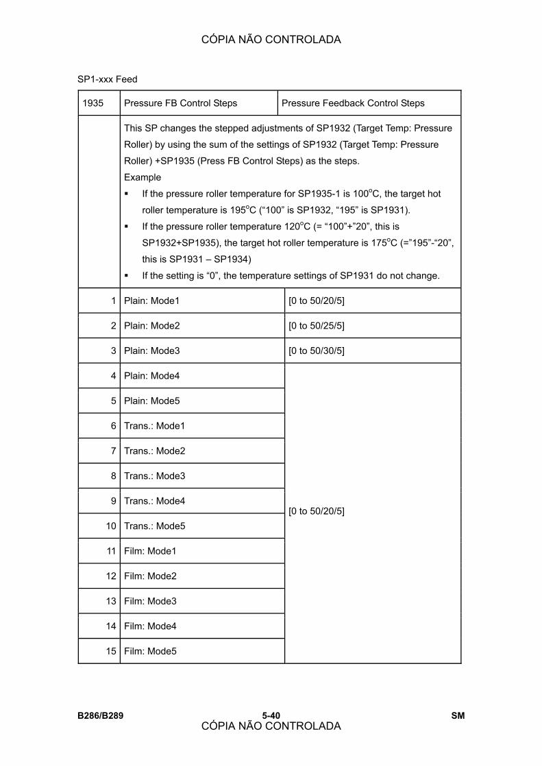
SP1-xxx Feed
B286/B289 5-40 SM
1935 Pressure FB Control Steps Pressure Feedback Control Steps
This SP changes the stepped adjustments of SP1932 (Target Temp: Pressure
Roller) by using the sum of the settings of SP1932 (Target Temp: Pressure
Roller) +SP1935 (Press FB Control Steps) as the steps.
Example
! If the pressure roller temperature for SP1935-1 is 100oC, the target hot
roller temperature is 195oC (�100� is SP1932, �195� is SP1931).
! If the pressure roller temperature 120oC (= �100�+�20�, this is
SP1932+SP1935), the target hot roller temperature is 175oC (=�195�-�20�,
this is SP1931 � SP1934)
! If the setting is �0�, the temperature settings of SP1931 do not change.
1 Plain: Mode1 [0 to 50/20/5]
2 Plain: Mode2 [0 to 50/25/5]
3 Plain: Mode3 [0 to 50/30/5]
4 Plain: Mode4
5 Plain: Mode5
6 Trans.: Mode1
7 Trans.: Mode2
8 Trans.: Mode3
9 Trans.: Mode4
10 Trans.: Mode5
11 Film: Mode1
12 Film: Mode2
13 Film: Mode3
14 Film: Mode4
15 Film: Mode5
[0 to 50/20/5]
CÓPIA NÃO CONTROLADA
CÓPIA NÃO CONTROLADA
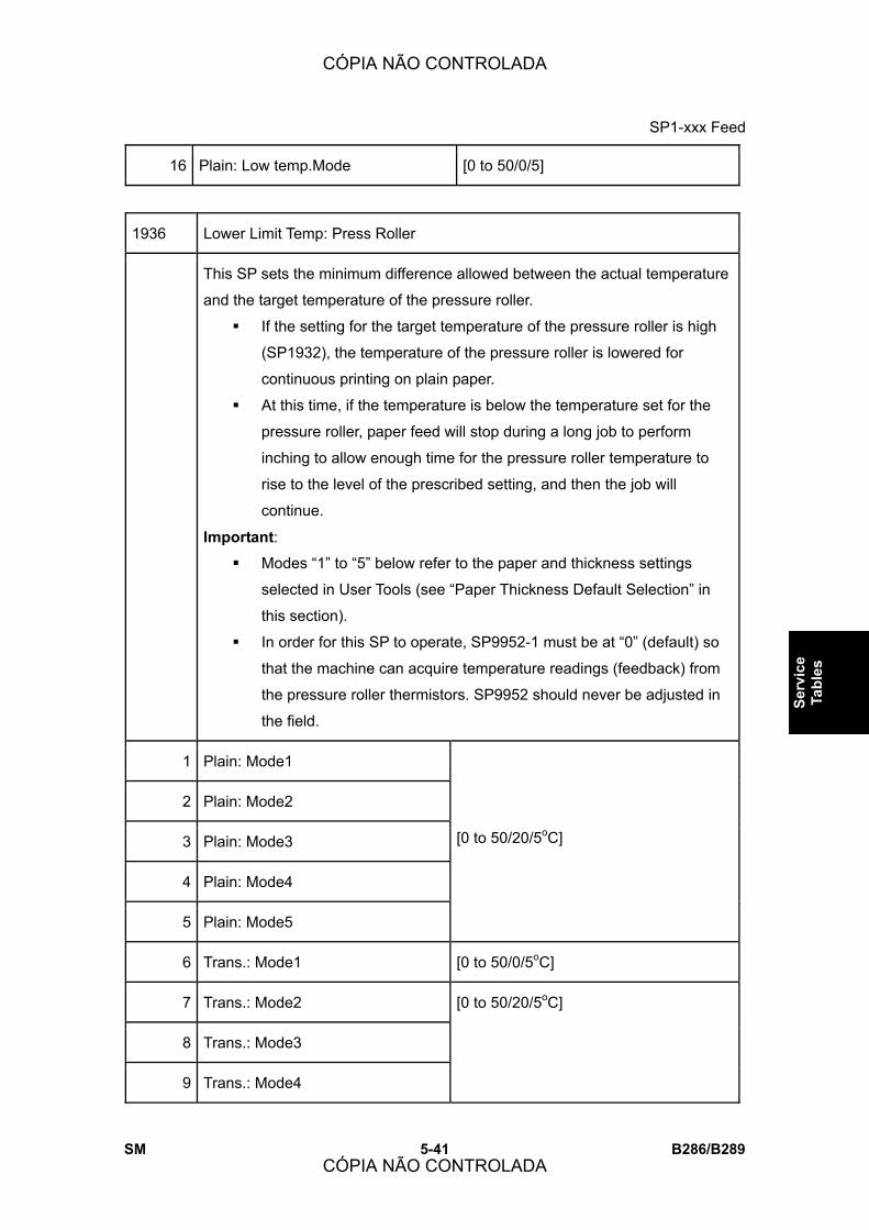
SP1-xxx Feed
SM 5-41 B286/B289
Serv
ice
Tabl
es
16 Plain: Low temp.Mode [0 to 50/0/5]
1936 Lower Limit Temp: Press Roller
This SP sets the minimum difference allowed between the actual temperature
and the target temperature of the pressure roller.
! If the setting for the target temperature of the pressure roller is high
(SP1932), the temperature of the pressure roller is lowered for
continuous printing on plain paper.
! At this time, if the temperature is below the temperature set for the
pressure roller, paper feed will stop during a long job to perform
inching to allow enough time for the pressure roller temperature to
rise to the level of the prescribed setting, and then the job will
continue.
Important: ! Modes �1� to �5� below refer to the paper and thickness settings
selected in User Tools (see �Paper Thickness Default Selection� in
this section).
! In order for this SP to operate, SP9952-1 must be at �0� (default) so
that the machine can acquire temperature readings (feedback) from
the pressure roller thermistors. SP9952 should never be adjusted in
the field.
1 Plain: Mode1
2 Plain: Mode2
3 Plain: Mode3
4 Plain: Mode4
5 Plain: Mode5
[0 to 50/20/5oC]
6 Trans.: Mode1 [0 to 50/0/5oC]
7 Trans.: Mode2
8 Trans.: Mode3
9 Trans.: Mode4
[0 to 50/20/5oC]
CÓPIA NÃO CONTROLADA
CÓPIA NÃO CONTROLADA

SP1-xxx Feed
B286/B289 5-42 SM
10 Trans.: Mode5
11 Film: Mode1
12 Film: Mode2
13 Film: Mode3
14 Film: Mode4
15 Film: Mode5
1937 Low Temp Environ Detect Ctrl
These SP�s are used to modify fusing temperature control sequence in a low
temperature environment where room temperature is below the optimum room
temperature of 20oC (68oF).
Note
! At optimum room temperature, the machine should reach the target fusing
temperature within 2 min.
! If the hot roller does not reach the target fusing temperature within 2
minutes, the machine issues SC542 (Fusing Temperature Warmup Error).
1 Low Temp Setting
The machine monitors the time required for the hot roller temperature to reach
the critical temperature defined by this SP:
Copy Ready Temperature (SP1105-1) - This SP Value (Default: 20oC)
In a low temperature environment copying will not begin at the normal copy
ready temperature.
[0 to 50/20/5]
2 Low Temp Time Setting
This SP sets the length of time within which the hot roller temperature should
reach the target temperature set with SP1937-1. If the hot roller does not reach
the SP1937-1 temperature within this time limit, the machine will not allow
copying to start when the temperature reaches the ready temperature.
[0 to 120/120/1 sec.]
CÓPIA NÃO CONTROLADA
CÓPIA NÃO CONTROLADA

SP1-xxx Feed
SM 5-43 B286/B289
Serv
ice
Tabl
es
3 Pressure Inching Start: Temp
If the inching target temperature (set with SP1948) is higher than 65oC, inching
will start when the hot roller temperature reaches this target hot roller
temperature. If the pressure roller temperature is less than 60oC, inching will
start at the ready (reload) temperature.
This SP sets the temperature at which inching starts in a low-temperature
environment where fusing temperature control is handled with the settings of
SP1937.
[0 to 50/20/5]
11 Low Temp Mode Setting: Cold Start
If the hot roller temperature is below the temperature set with this SP at the
beginning of a cold start, the machine determines that it is in a low temperature
environment
[0 to 50/15/1]
12 Low Temp Mode Setting: Cold Start Hold Time
This SP determines the length of time the machine remains in the low
temperature cold start mode after the machine determines that that it has been
cold started in a low temperature environment. After this time has elapsed,
fusing temperature control will operate with the paper type and thickness
settings (see �Paper Thickness Default Selection� in this section).
[0 to 20/7/0.5 min.]
13 Low Temp Mode Paper Interval Ratio
This SP sets the size of the gap between sheets of paper while the machine is in
the low temperature environment cold start mode.
[1 to 10/3/0.1 mm]
CÓPIA NÃO CONTROLADA
CÓPIA NÃO CONTROLADA

SP1-xxx Feed
B286/B289 5-44 SM
1938 Press FB Ctrl Step Width Switch
This SP switches step control by width on and off. After this SP has been
switched on, the step control by width can be set up with SP1939 002 to 004.
Note:
! These settings can be done for each paper type and thickness mode.
! Modes �1� to �5� below refer to the paper and thickness settings selected in
User Tools (see �Paper Thickness Default Selection� in this section).
1 Plain: Mode1
2 Plain: Mode2
3 Plain: Mode3
4 Plain: Mode4
5 Plain: Mode5
6 Trans.: Mode1
7 Trans.: Mode2
8 Trans.: Mode3
9 Trans.: Mode4
10 Trans.: Mode5
11 Film: Mode1
12 Film: Mode2
13 Film: Mode3
14 Film: Mode4
15 Film: Mode5
[0 to 1/0/1]
0: Disabled
1: Enabled
CÓPIA NÃO CONTROLADA
CÓPIA NÃO CONTROLADA
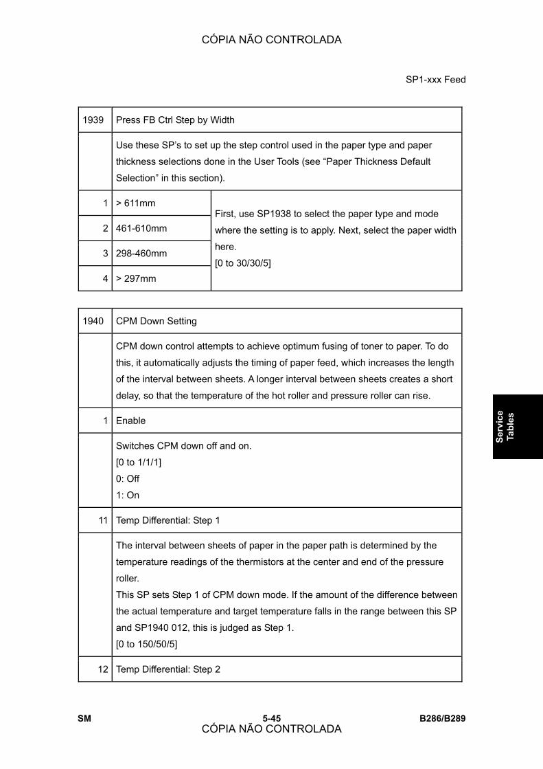
SP1-xxx Feed
SM 5-45 B286/B289
Serv
ice
Tabl
es
1939 Press FB Ctrl Step by Width
Use these SP�s to set up the step control used in the paper type and paper
thickness selections done in the User Tools (see �Paper Thickness Default
Selection� in this section).
1 > 611mm
2 461-610mm
3 298-460mm
4 > 297mm
First, use SP1938 to select the paper type and mode
where the setting is to apply. Next, select the paper width
here.
[0 to 30/30/5]
1940 CPM Down Setting
CPM down control attempts to achieve optimum fusing of toner to paper. To do
this, it automatically adjusts the timing of paper feed, which increases the length
of the interval between sheets. A longer interval between sheets creates a short
delay, so that the temperature of the hot roller and pressure roller can rise.
1 Enable
Switches CPM down off and on.
[0 to 1/1/1]
0: Off
1: On
11 Temp Differential: Step 1
The interval between sheets of paper in the paper path is determined by the
temperature readings of the thermistors at the center and end of the pressure
roller.
This SP sets Step 1 of CPM down mode. If the amount of the difference between
the actual temperature and target temperature falls in the range between this SP
and SP1940 012, this is judged as Step 1.
[0 to 150/50/5]
12 Temp Differential: Step 2
CÓPIA NÃO CONTROLADA
CÓPIA NÃO CONTROLADA

SP1-xxx Feed
B286/B289 5-46 SM
This SP sets Step 2 of CPM down mode. If the amount of the difference between
the actual temperature and target temperature falls in the range between this SP
and SP1940 013, this is judged as Step 2.
[0 to 150/75/5]
13
Temp Differential: Step 3
This SP sets Step 3 of CPM down mode. If the difference between actual and
target temperature is larger than this SP setting, this is judged as Step 3.
[0 to 150/100/5]
21 Paper Interval: Step 1
When the pressure roller center and end thermistor detect a temperature in the
Step 1 range (SP1940 011), the setting of this SP is activated to set the length of
the interval between sheets in the paper path.
[1.0 to 5.0/1.4/0.1]
The default setting (1.4) is the variable for Step 1 multiplied by the constant set
for Step 1 of the machine:
! B286: 480 mm. The default interval is 672 mm (1.4 x 480 mm).
! B289: 168 mm. The default interval is 235 mm (1.4 x 168 mm).
Setting a smaller or larger number decreases or increases the length of the
interval with this simple calculation. This standard interval can be modified
slightly with SP1923.
22 Paper Interval Step 2
When the pressure roller center and end thermistor detect a temperature in the
Step 2 range (SP1940 012), the setting of this SP is activated to set the length of
the interval between sheets in the paper path.
[1.0 to 5.0/2.1/0.1]
The default setting (2.1) is the variable for Step 2 multiplied by the constant set
for Step 2 of the machine:
! B286: 480 mm. The default interval is 1008 mm (2.1 x 480 mm).
! B289: 168 mm. The default interval is 353 mm (2.1 x 168 mm).
Setting a smaller or larger number decreases or increases the length of the
interval with this simple calculation. This standard interval can be modified
slightly with SP1923.
CÓPIA NÃO CONTROLADA
CÓPIA NÃO CONTROLADA
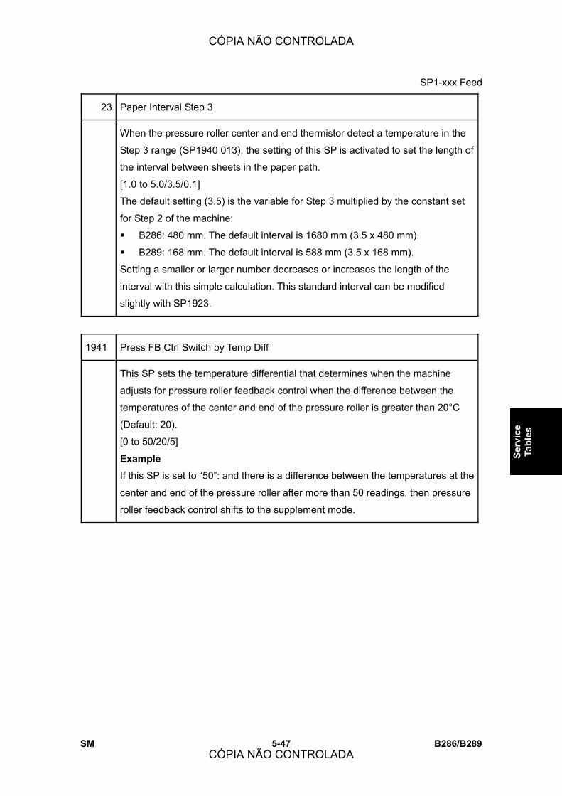
SP1-xxx Feed
SM 5-47 B286/B289
Serv
ice
Tabl
es
23 Paper Interval Step 3
When the pressure roller center and end thermistor detect a temperature in the
Step 3 range (SP1940 013), the setting of this SP is activated to set the length of
the interval between sheets in the paper path.
[1.0 to 5.0/3.5/0.1]
The default setting (3.5) is the variable for Step 3 multiplied by the constant set
for Step 2 of the machine:
! B286: 480 mm. The default interval is 1680 mm (3.5 x 480 mm).
! B289: 168 mm. The default interval is 588 mm (3.5 x 168 mm).
Setting a smaller or larger number decreases or increases the length of the
interval with this simple calculation. This standard interval can be modified
slightly with SP1923.
1941 Press FB Ctrl Switch by Temp Diff
This SP sets the temperature differential that determines when the machine
adjusts for pressure roller feedback control when the difference between the
temperatures of the center and end of the pressure roller is greater than 20°C
(Default: 20).
[0 to 50/20/5]
Example
If this SP is set to �50�: and there is a difference between the temperatures at the
center and end of the pressure roller after more than 50 readings, then pressure
roller feedback control shifts to the supplement mode.
CÓPIA NÃO CONTROLADA
CÓPIA NÃO CONTROLADA
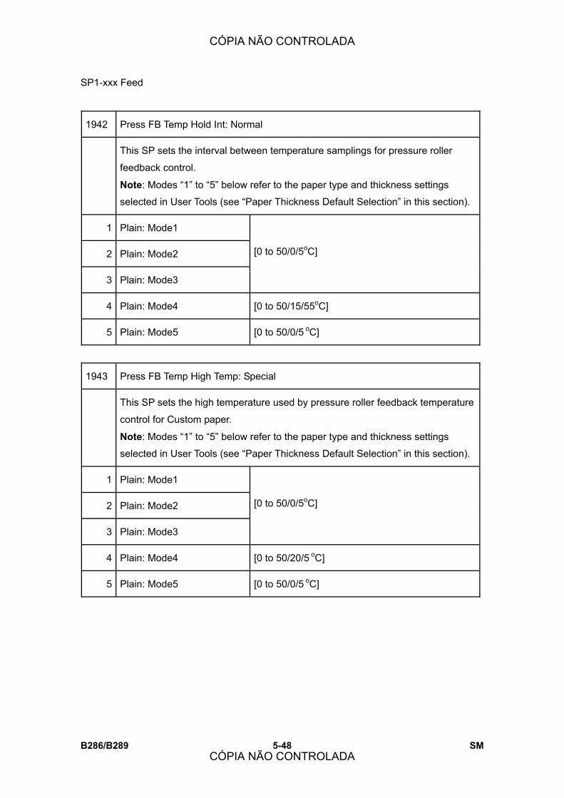
SP1-xxx Feed
B286/B289 5-48 SM
1942 Press FB Temp Hold Int: Normal
This SP sets the interval between temperature samplings for pressure roller
feedback control.
Note: Modes �1� to �5� below refer to the paper type and thickness settings
selected in User Tools (see �Paper Thickness Default Selection� in this section).
1 Plain: Mode1
2 Plain: Mode2
3 Plain: Mode3
[0 to 50/0/5oC]
4 Plain: Mode4 [0 to 50/15/55oC]
5 Plain: Mode5 [0 to 50/0/5 oC]
1943 Press FB Temp High Temp: Special
This SP sets the high temperature used by pressure roller feedback temperature
control for Custom paper.
Note: Modes �1� to �5� below refer to the paper type and thickness settings
selected in User Tools (see �Paper Thickness Default Selection� in this section).
1 Plain: Mode1
2 Plain: Mode2
3 Plain: Mode3
[0 to 50/0/5oC]
4 Plain: Mode4 [0 to 50/20/5 oC]
5 Plain: Mode5 [0 to 50/0/5 oC]
CÓPIA NÃO CONTROLADA
CÓPIA NÃO CONTROLADA

SP1-xxx Feed
SM 5-49 B286/B289
Serv
ice
Tabl
es
1944 Press FB Temp Low Temp: Special
This SP sets the low temperature used by pressure roller feedback temperature
control for Custom paper.
Note: Modes �1� to �5� below refer to the paper type and thickness settings
selected in User Tools (see �Paper Thickness Default Selection� in this section).
1 Plain: Mode1
2 Plain: Mode2
3 Plain: Mode3
[0 to 50/0/5oC]
4 Plain: Mode4 [0 to 50/10/5 oC]
5 Plain: Mode5 [0 to 50/5/5 oC]
1945 Length Level Setting
These SP�s define the Length Levels for the following SP codes:
! SP1946 Press FB Stop: Target Temp Diff.
! SP1947 Press FB Stop: Time Period
1 Level 1 [1000 to 15000/1300/1 mm]
2 Level 2 [1000 to 15000/3700/1 mm]
3 Level 3 [1000 to 15000/61001 mm]
4 Level 4 [1000 to 15000/9100/1 mm]
5 Level 5 [1000 to 15000/12100/1 mm]
CÓPIA NÃO CONTROLADA
CÓPIA NÃO CONTROLADA
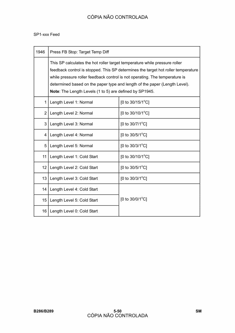
SP1-xxx Feed
B286/B289 5-50 SM
1946 Press FB Stop: Target Temp Diff
This SP calculates the hot roller target temperature while pressure roller
feedback control is stopped. This SP determines the target hot roller temperature
while pressure roller feedback control is not operating. The temperature is
determined based on the paper type and length of the paper (Length Level).
Note: The Length Levels (1 to 5) are defined by SP1945.
1 Length Level 1: Normal [0 to 30/15/1oC]
2 Length Level 2: Normal [0 to 30/10/1oC]
3 Length Level 3: Normal [0 to 30/7/1oC]
4 Length Level 4: Normal [0 to 30/5/1oC]
5 Length Level 5: Normal [0 to 30/3/1oC]
11 Length Level 1: Cold Start [0 to 30/10/1oC]
12 Length Level 2: Cold Start [0 to 30/5/1oC]
13 Length Level 3: Cold Start [0 to 30/3/1oC]
14 Length Level 4: Cold Start
15 Length Level 5: Cold Start
16 Length Level 0: Cold Start
[0 to 30/0/1oC]
CÓPIA NÃO CONTROLADA
CÓPIA NÃO CONTROLADA

SP1-xxx Feed
SM 5-51 B286/B289
Serv
ice
Tabl
es
1947 Press FB Stop: Time Period
This SP sets the length of time that pressure roller feedback is suspended for the
paper lengths defined by SP1945.
! Pressure roller feedback control begins when the time set with this SP has
elapsed after paper feed starts.
! As more paper is fed for a multiple print job, the time setting for succeeding
sheets is overwritten.
! However, for succeeding sheets where the time prescribed for feedback
suspension is �0�, the �0� value is not overwritten, but feedback suspension
control is maintained until countdown for the multiple copies is finished.
1 Length Level 1: Normal [0 to 300/15/1 sec.]
2 Length Level 2: Normal [0 to 300/30/1 sec.]
3 Length Level 3: Normal [0 to 300/45/1 sec.]
4 Length Level 4: Normal [0 to 300/60/1 sec.]
5 Length Level 5: Normal [0 to 300/80/1 sec.]
11 Length Level 1: Cold Start [0 to 300/20/1 sec.]
12 Length Level 2: Cold Start [0 to 300/35/1 sec.]
13 Length Level 3: Cold Start [0 to 300/50/1 sec.]
14 Length Level 4: Cold Start [0 to 300/70/1 sec.]
15 Length Level 5: Cold Start [0 to 300/100/1 sec.]
16 Length Level 0: Cold Start
Normally, pressure roller feedback control does not operate when the paper
length is not prescribed (length = 0). But if copying was started while feedback
control was not operating, during a cold start for example, then feedback control
operates using the setting of this SP code.
[0 to 300/15/1 sec.]
CÓPIA NÃO CONTROLADA
CÓPIA NÃO CONTROLADA

SP1-xxx Feed
B286/B289 5-52 SM
17 Length Level 0: False Start
The target hot roller temperature for a flying start is determined by SP1931. This
SP determines the time limit for the hot roller to reach that target hot roller
temperature.
[0 to 300/20/1 sec.]
18 Standby After Cold Start
This SP sets a time period that prohibits printing to begin even after the hot roller
temperature reaches its target temperature after a cold start. If a job is started
during this time period countdown, the countdown changes to the counts for-11 to
-17 above.
[0 to 300/60/1 sec.]
1948 Press Roller Inching Target Temp
This SP determines when inching starts.
! Inching control is done when the pressure roller temperature is above this
setting (65oC for example), but printing is prohibited until the pressure roller
temperature reaches its target temperature.
! Inching (idle rotation of the rollers) starts after the temperature rises above
the hot roller target temperature (SP1937 003).
! While the temperature is below 65oC copying (not printing) is possible before
the temperature of the pressure roller reaches its target temperature and
inching starts.
1 Plain: Mode1 [60 to 180/100/5oC]
2 Plain: Mode2 [60 to 180/65/5oC]
3 Plain: Mode3
4 Plain: Mode4
5 Plain: Mode5
[60 to 180/60/5oC]
6 Trans.: Mode1 [60 to 180/130/5oC]
CÓPIA NÃO CONTROLADA
CÓPIA NÃO CONTROLADA

SP1-xxx Feed
SM 5-53 B286/B289
Serv
ice
Tabl
es
7 Trans.: Mode2 [60 to 180/100/5oC]
8 Trans.: Mode3
9 Trans.: Mode4
10 Trans.: Mode5
11 Film: Mode1
12 Film: Mode2
13 Film: Mode3
14 Film: Mode4
15 Film: Mode5
[60 to 180/60/5oC]
16 Plain Mode: Low Temp Cold Start
When the machine determines that a cold start in a low-temperature environment
has started, the machine uses this setting to start the machine and ignores the
paper thickness mode settings.
! When the prescribed time has elapsed after a cold start, temperature control
returns to the paper type and thickness settings.
! However, this low temperature cold start does temperature control for plain
paper only, not for either translucent paper or film.
[60 to 80/120/5oC]
CÓPIA NÃO CONTROLADA
CÓPIA NÃO CONTROLADA

SP1-xxx Feed
B286/B289 5-54 SM
1949 Press FB Std Temp Coeff
The formula above uses the setting of this SP to determine the pressure roller
feedback temperature. The result of this calculation is used to calculate the hot
roller target temperature.
Note:
! Settings can be selected below for the paper type, mode, and paper length.
! Modes �1� to �5� below refer to the paper type and thickness settings
selected in User Tools (see �Paper Thickness Default Selection� in this
section).
11 Normal Mode1: > 611mm [0 to 1/0/0.1]
12 Normal Mode1: 461-610mm
13 Normal Mode1: 298-460
14 Normal Mode1: < 297mm
21 Normal Mode2: > 611mm
22 Normal Mode2: 461-610mm
23 Normal Mode2: 298-460
24 Normal Mode2: < 297mm
31 Normal Mode3: > 611mm
32 Normal Mode3: 461-610mm
33 Normal Mode3: 298-460
34 Normal Mode3: < 297mm
41 Normal Mode4: > 611mm
CÓPIA NÃO CONTROLADA
CÓPIA NÃO CONTROLADA

SP1-xxx Feed
SM 5-55 B286/B289
Serv
ice
Tabl
es
42 Normal Mode4: 461-610mm
43 Normal Mode4: 298-460
44 Normal Mode4: < 297mm
51 Normal Mode5: > 611mm
52 Normal Mode5: 461-610mm
53 Normal Mode5: 298-460
54 Normal Mode5: < 297mm
61 Trans Mode: > 611mm
62 Trans Mode: 461-610mm
63 Trans Mode: 298-460
64 Trans Mode: < 297mm
111 Film Mode: > 611mm
112 Film Mode: 461-610mm
113 Film Mode: 298-460
114 Film Mode: < 297mm
1970 Fan Stop Time
This SP sets the fan stop time.
[0 to 30/1/1 min.]
CÓPIA NÃO CONTROLADA
CÓPIA NÃO CONTROLADA
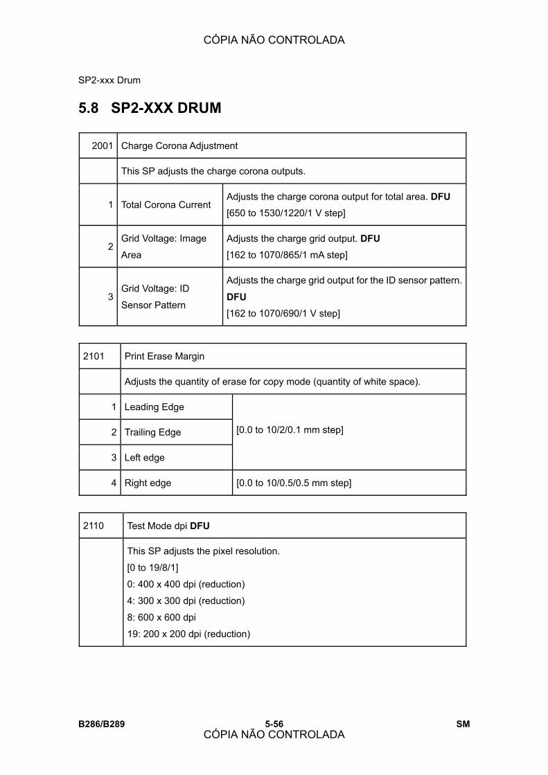
SP2-xxx Drum
B286/B289 5-56 SM
5.8 SP2-XXX DRUM
2001 Charge Corona Adjustment
This SP adjusts the charge corona outputs.
1 Total Corona Current Adjusts the charge corona output for total area. DFU
[650 to 1530/1220/1 V step]
2 Grid Voltage: Image
Area
Adjusts the charge grid output. DFU
[162 to 1070/865/1 mA step]
3 Grid Voltage: ID
Sensor Pattern
Adjusts the charge grid output for the ID sensor pattern.
DFU
[162 to 1070/690/1 V step]
2101 Print Erase Margin
Adjusts the quantity of erase for copy mode (quantity of white space).
1 Leading Edge
2 Trailing Edge
3 Left edge
[0.0 to 10/2/0.1 mm step]
4 Right edge [0.0 to 10/0.5/0.5 mm step]
2110 Test Mode dpi DFU
This SP adjusts the pixel resolution.
[0 to 19/8/1]
0: 400 x 400 dpi (reduction)
4: 300 x 300 dpi (reduction)
8: 600 x 600 dpi
19: 200 x 200 dpi (reduction)
CÓPIA NÃO CONTROLADA
CÓPIA NÃO CONTROLADA

SP2-xxx Drum
SM 5-57 B286/B289
Serv
ice
Tabl
es
2201 Development Bias Adjustment
This SP sets the development bias to adjust the amount of toner used in the
image area.
1 Image Area [-56 to -952/-650/1 V step]
2 ID Sensor Pattern: Low Duty Copy Jobs [-56 to -952/-414/1 V step]
3 ID Sensor Pattern: High Duty Copy Jobs [56 to 952/453/1 V step]
4 Copy Jobs
[0 to 1/0/1]
0: Low Duty Mode
1: High Duty Mode
2207 Forced Toner Supply
Push [Execute] to force toner supply. Make a copy and check the image
density. This SP supplies more toner to make light copies darker. Each time
this SP is done, toner is supplied one time.
CÓPIA NÃO CONTROLADA
CÓPIA NÃO CONTROLADA

SP2-xxx Drum
B286/B289 5-58 SM
2208 Toner Supply Setting
1 Gain
Sets the toner supply capacity for the job load.
[0 to 3/1/1]
0: L (Low)
1: M (Medium)
2: H (High)
3: HH (Very High)
3 Toner Supply
Mode
Sets the toner supply mode.
0: Detect Mode (uses ID sensor)
1: Fixed Mode
! If the ID sensor is damaged and cannot be replaced
immediately, set this SP to �1.� The operator can
continue to use the machine until a new ID sensor
becomes available.
! After the ID sensor has been replaced, reset this SP to
0.
2301 Transfer Current Adjustment
Use these SP�s to adjust the coefficient and power output used to develop the
image at the center, leading edge, and trailing edge.
Note: Always do the coefficient adjustment first, then adjust the power output.
1 Plain Paper: Img LEdge
2 Plain Paper: Img Area
3 Plain Paper: Img TEdge
Adjusts the transfer output power for plain
paper. DFU
[0 to 230/60/1 mA]
4 Plain Paper: Coefficient
Adjusts the transfer output coefficient for
the image at the center, leading edge, and
trailing edge on plain paper. DFU
[1.0 to 2.0/1.0/0.2 step]
5 Translucent: Img LEdge Adjusts the transfer output power for
CÓPIA NÃO CONTROLADA
CÓPIA NÃO CONTROLADA
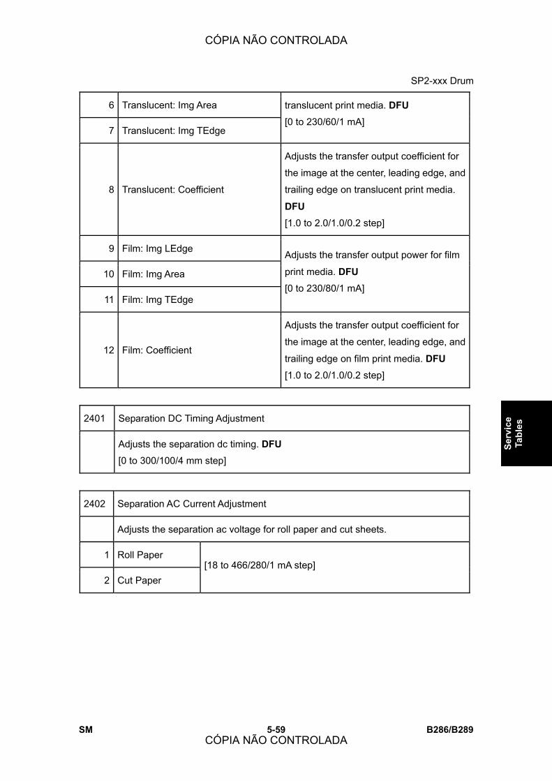
SP2-xxx Drum
SM 5-59 B286/B289
Serv
ice
Tabl
es
6 Translucent: Img Area
7 Translucent: Img TEdge
translucent print media. DFU
[0 to 230/60/1 mA]
8 Translucent: Coefficient
Adjusts the transfer output coefficient for
the image at the center, leading edge, and
trailing edge on translucent print media.
DFU
[1.0 to 2.0/1.0/0.2 step]
9 Film: Img LEdge
10 Film: Img Area
11 Film: Img TEdge
Adjusts the transfer output power for film
print media. DFU
[0 to 230/80/1 mA]
12 Film: Coefficient
Adjusts the transfer output coefficient for
the image at the center, leading edge, and
trailing edge on film print media. DFU
[1.0 to 2.0/1.0/0.2 step]
2401 Separation DC Timing Adjustment
Adjusts the separation dc timing. DFU
[0 to 300/100/4 mm step]
2402 Separation AC Current Adjustment
Adjusts the separation ac voltage for roll paper and cut sheets.
1 Roll Paper
2 Cut Paper [18 to 466/280/1 mA step]
CÓPIA NÃO CONTROLADA
CÓPIA NÃO CONTROLADA
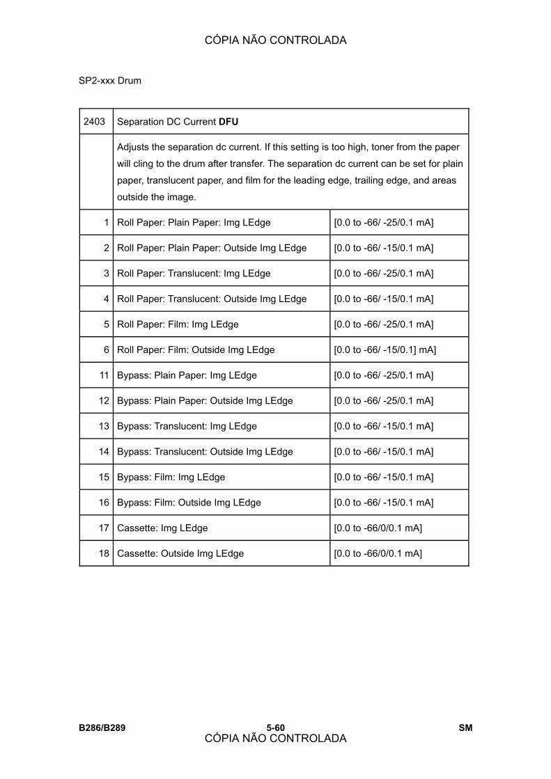
SP2-xxx Drum
B286/B289 5-60 SM
2403 Separation DC Current DFU
Adjusts the separation dc current. If this setting is too high, toner from the paper
will cling to the drum after transfer. The separation dc current can be set for plain
paper, translucent paper, and film for the leading edge, trailing edge, and areas
outside the image.
1 Roll Paper: Plain Paper: Img LEdge [0.0 to -66/ -25/0.1 mA]
2 Roll Paper: Plain Paper: Outside Img LEdge [0.0 to -66/ -15/0.1 mA]
3 Roll Paper: Translucent: Img LEdge [0.0 to -66/ -25/0.1 mA]
4 Roll Paper: Translucent: Outside Img LEdge [0.0 to -66/ -15/0.1 mA]
5 Roll Paper: Film: Img LEdge [0.0 to -66/ -25/0.1 mA]
6 Roll Paper: Film: Outside Img LEdge [0.0 to -66/ -15/0.1] mA]
11 Bypass: Plain Paper: Img LEdge [0.0 to -66/ -25/0.1 mA]
12 Bypass: Plain Paper: Outside Img LEdge [0.0 to -66/ -25/0.1 mA]
13 Bypass: Translucent: Img LEdge [0.0 to -66/ -15/0.1 mA]
14 Bypass: Translucent: Outside Img LEdge [0.0 to -66/ -15/0.1 mA]
15 Bypass: Film: Img LEdge [0.0 to -66/ -15/0.1 mA]
16 Bypass: Film: Outside Img LEdge [0.0 to -66/ -15/0.1 mA]
17 Cassette: Img LEdge [0.0 to -66/0/0.1 mA]
18 Cassette: Outside Img LEdge [0.0 to -66/0/0.1 mA]
CÓPIA NÃO CONTROLADA
CÓPIA NÃO CONTROLADA

SP2-xxx Drum
SM 5-61 B286/B289
Serv
ice
Tabl
es
2801 Initialize Developer
This SP mixes the developer and initializes the ID sensor. Use this SP to mix the
developer during machine installation or after the developer has been replaced.
The machine requires two packs of developer. Two SP codes are provided for
entering the lot numbers of both packages.
Note:
! Always enter the lot numbers with SP2801-2 and -3 before doing SP2801-1.
1 Developer Initial Setting: Execute Mixes developer and initializes the ID
sensor
2 Lot Number 1 Lot number of the 1st packet.
3 Lot Number 2 Lot number of the 2nd packet.
2803 Corona Wire: Cleaning Start
Do this SP to clean the charge corona wire. This SP also moves the cleaning pad
to the home position. The cleaning requires about 20 sec. to complete.
2804 Corona Wire: Cleaning Interval
Sets the interval for charge corona wire cleaning.
Note: The wire is cleaned only when the hot roller temperature is below 50 °C
(122oF).
[0 to 6/3/1 step]
0: None (no cleaning)
1: After the main switch is turned on.
2: After 300 m of copies
3: After 600 m of copies
4: After 900 m of copies
5: After 1200 m of copies
6: After 1500 m of copies
CÓPIA NÃO CONTROLADA
CÓPIA NÃO CONTROLADA

SP2-xxx Drum
B286/B289 5-62 SM
2805 Drum Motor Speed DFU
This SP adjusts the drum motor speed.
1 Width:420mm more
2 Width:420mm less
2902 Test Pattern
Use these SP�s to select and print test patterns.
1 IPU Scanning Test Pattern
(See section 5.8.1 Test Pattern Printing for instructions)
Select this test pattern if you suspect there is a problem with scanning. Select
one of 17 available test patterns (1-17). [0 to 17/0/1]
* 0: None 9: Vertical Grayscale (16-level)
1: Vertical Line (1-dot) 10: Grayscale (16-level)
2: Vertical Line (2-dot) 11: Cross Pattern
3: Horizontal Line (1-dot) 12: Argyle Pattern
4: Horizontal Line (2-dot) 13: Density Patch (256-level)
5: Independent Dot (1-dot) 14: Density Patch (64-level)
6: Grid Pattern (1-dot) 15: Trimming Area
7: Vertical Stripes 16: Bandwidth (Vertical)
8: Horizontal Gray (16-level) 17: Bandwidth (Horizontal)
2 IPU Printing Test Pattern (See section 5.8.1 Test Pattern Printing for instructions)
Select this test pattern if you suspect there is a problem with image printing.
Select one of 11 available test patterns (1-11). Refer to �3. Replacement and
Adjustment� for more details about how to use these patterns to check these
items:
CÓPIA NÃO CONTROLADA
CÓPIA NÃO CONTROLADA

SP2-xxx Drum
SM 5-63 B286/B289
Serv
ice
Tabl
es
! Registration line speed (Pattern #11)
! Magnification (Pattern #11)
! LPH replacement (Pattern #11)
! Pattern density (Pattern #10)
[0 to 11/0/1]
* 0: None 6: Density Patch (64-level)
1: Independent Dot (1-4 dot)&Solid 7: Cross Pattern
2: Horizontal Grayscale (16-level) 8: Grid Pattern (96 dot width)
3: Vertical Grayscale (16-level) 9: Argyle Pattern
4: Grayscale (16-level) 10: Grayscale Horizontal (8-level &
line)
5: Density Patch (256-level) 11: Grid Pattern (128 dot width)
3 Printing Test Pattern (See section 5.8.1 Test Pattern Printing for instructions)
Select this test pattern if you suspect there is a problem with image writing.
Select one of 25 available test patterns (1-25).
[0 to 25/0/1]
0: None (default)
* 0: None 13: Vertical Line (1-dot)
1: Grid Pattern (1-dot) 14: Vertical Line (2-dot)
2: Grid Pattern (2-dot) 15: Horizontal Line (1-dot)
3: Grid Pattern (3-dot) 16: Horizontal Line (2-dot)
4: Grid Pattern (4-dot) 17: Checkered Flag
5: Grid Pattern (5-dot) 18: Alternating Dot Pattern (1-dot)
6: Grid Pattern (6-dot) 19: Alternating Dot Pattern (2-dot)
7: Argyle Pattern (1-dot) 20: Alternating Dot Pattern (4-dot)
8: Argyle Pattern (2-dot) 21: Trimming Area
CÓPIA NÃO CONTROLADA
CÓPIA NÃO CONTROLADA

SP2-xxx Drum
B286/B289 5-64 SM
9: Argyle Pattern (3-dot) 22: Full Dot Pattern
10: Argyle Pattern (4-dot) 23: Black Band (Vertical)
11: Argyle Pattern (5-dot) 24: Black Band (Horizontal)
12: Argyle Pattern (6-dot) 25: Blank Image
2909 Main Scan Magnification
This SP fine adjusts magnification of the copy image in the main scan direction.
[-10 to +10/0/0.1%]
2916 Fine Magnification
Adjusts the magnification for each paper type. These settings are enabled
automatically for the paper type when the operator selects a magnification ratio
for the copy job. These corrections are done during image processing after the
original is scanned. Adjust the setting for a paper type if you consistently notice
distortion in magnified images for a particular type.
[-10 to +10/0/0.1%]
Notes
! SP2916-1, SP2916-2 should be adjusted at installation of the main
machine. In �1. Installation� See section 3.11.
1 Plain Paper: Mode1-4: Horiz
2 Plain Paper: Mode1-4: Vert
3 Translucent: Mode1-4: Horiz
4 Translucent: Mode1-4: Vert
5 Film: Mode1-4: Horiz
6 Film: Mode1-4: Vert
7 Recycled Paper: Mode1-4: Horiz
8 Recycled Paper: Mode1-4: Vert
CÓPIA NÃO CONTROLADA
CÓPIA NÃO CONTROLADA

SP2-xxx Drum
SM 5-65 B286/B289
Serv
ice
Tabl
es
9 Plain Paper: Mode5: Horiz
10 Plain Paper: Mode5: Vert
11 Translucent: Mode5: Horiz
12 Translucent: Mode5: Vert
13 Film: Mode5: Horiz
14 Film: Mode5: Vert
15 Recycled Paper: Mode5: Horiz
16 Recycled Paper: Mode5: Vert
2923 Execute Cleaning Blade Replace Mode
Always do this SP after replacing the OPC or cleaning blade.
This SP applies a small amount of toner to the drum and blade to reduce
friction between the new drum and/or new blade. This prevents scratching the
drum or bending the blade.
2924 Developer Mixing: Warmup
Enables/disables measurement of Vsg during warm-up immediately after the
machine is switched on. Vsg sampling is done to ensure good quality for the
first copies.
[0 to 2/0/1]
0: Vsg is read immediately after the machine is switched on with the fusing
temperature less than 50°C (122oF).
1: Vsg is always read during warm-up immediately after the machine is
switched on, regardless of the fusing temperature level.
2: Vsg is not read during warm-up.
CÓPIA NÃO CONTROLADA
CÓPIA NÃO CONTROLADA

SP2-xxx Drum
B286/B289 5-66 SM
2925 Transfer Current Timing DFU
These SP�s adjust the transfer current timing.
1 ON Adjusts the timing for power on.
[0 to 16/6/0.2 mm]
2 Leading Edge
Adjusts the timing for switching from the leading edge to
the center.
[0 to 30/8/1 mm]
3 Trailing Edge
Adjusts the timing for switching from the center to the
trailing edge.
[-30 to 0/0/1 mm]
2926 Used Toner Overflow Detect
The used toner bottle motor operates a cam. This cam strikes the side of the
used toner collection bottle, to create a vibration that levels the used toner inside
the bottle.
1 Used Tnr M (Sensor Detection)
Sets the length of time that the used toner bottle motor operates. The motor
starts 10 sec. after the main power switch is switched on and if the fusing
temperature is less than 50°C (122oF).
[0 to 30/20/5]
Note: Ten seconds after the machine is switched on, if the machine detects that
the toner collection bottle is full, the used toner bottle motor does not operate.
2 Used Tnr M (TE Recovery)
Sets the length of time that the used toner bottle motor operates after TE (toner
end).
[0 to 80/30/5 sec.]
CÓPIA NÃO CONTROLADA
CÓPIA NÃO CONTROLADA
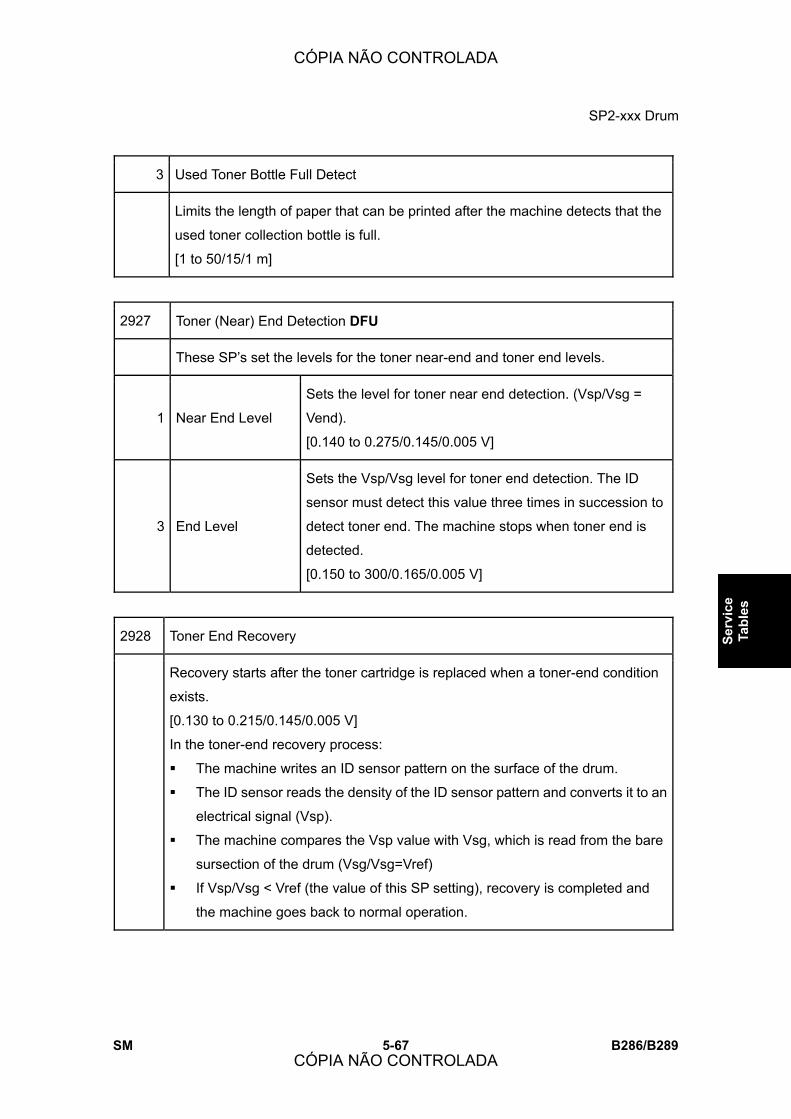
SP2-xxx Drum
SM 5-67 B286/B289
Serv
ice
Tabl
es
3 Used Toner Bottle Full Detect
Limits the length of paper that can be printed after the machine detects that the
used toner collection bottle is full.
[1 to 50/15/1 m]
2927 Toner (Near) End Detection DFU
These SP�s set the levels for the toner near-end and toner end levels.
1 Near End Level
Sets the level for toner near end detection. (Vsp/Vsg =
Vend).
[0.140 to 0.275/0.145/0.005 V]
3 End Level
Sets the Vsp/Vsg level for toner end detection. The ID
sensor must detect this value three times in succession to
detect toner end. The machine stops when toner end is
detected.
[0.150 to 300/0.165/0.005 V]
2928 Toner End Recovery
Recovery starts after the toner cartridge is replaced when a toner-end condition
exists.
[0.130 to 0.215/0.145/0.005 V]
In the toner-end recovery process:
! The machine writes an ID sensor pattern on the surface of the drum.
! The ID sensor reads the density of the ID sensor pattern and converts it to an
electrical signal (Vsp).
! The machine compares the Vsp value with Vsg, which is read from the bare
sursection of the drum (Vsg/Vsg=Vref)
! If Vsp/Vsg < Vref (the value of this SP setting), recovery is completed and
the machine goes back to normal operation.
CÓPIA NÃO CONTROLADA
CÓPIA NÃO CONTROLADA

SP2-xxx Drum
B286/B289 5-68 SM
2943 LED Duty Adjustment
Adjusts the on timing (the �width� or �duty�) of the LEDs in the LPH units to
change image exposure. Use this SP if it is necessary to make the output of one
LPH block brighter or darker. Raising the setting creates darker pixels, lowering
the setting creates lighter pixels.
1 LPH1
2 LPH2
3 LPH3
[1.0 to 32.0/12.0/0.1%]
The optimum LPH settings are printed on the label that is attached
to LPH replacement units. Always input these settings immediately
after the LPH unit has been replaced.
2944 LED Duty Rate DFU
This SP adjusts the power to the LPH.
[0 to 100/50/1%]
2952 LPH Joint Adjustment
Adjust these settings only after you replace the LPH. For more, refer to
�Replacement and Adjustment.�
1 LPH1-2 Main Scan
Adjusts the LPH joint for main scan between
LPH1 and LPH2.
[0 to 999/500/1]
2 LPH2-3 Main Scan
Adjusts the LPH joint for main scan between
LPH2 and LPH3.
[0 to 999/500/1]
11 LPH1-2 Sub Scan
Adjusts sub scanning at LPH 1-2 for paper
more than 420 mm wide.
[300 to 500/412/1]
12 LPH2-3 Sub Scan
Adjusts sub scanning at LPH 2-3 for paper
more than 420 mm wide.
[2 to 100/16/1]
CÓPIA NÃO CONTROLADA
CÓPIA NÃO CONTROLADA

SP2-xxx Drum
SM 5-69 B286/B289
Serv
ice
Tabl
es
51 LPH1-2 Sub Scan: < 420mm
Adjusts sub scanning at LPH 1-2 for paper
less than 420 mm wide. This value is
calculated automatically. Do not adjust.
[-50 to +50/0/1] DFU
52 LPH2-3 Sub Scan: < 420mm
Adjusts sub scanning at LPH 2-3 for paper
less than 420 mm wide. This value is
calculated automatically. Do not adjust.
[-50 to +50/0/1] DFU
2953 LPH Joint Power Corr
Adjusts the four LEDs at each end of LPH 2. This fine adjustment is not usually
necessary in the field.
[-63 to +63/0/1]
1 1-Dot: Left 011 1-Dot: Right
2 2-Dot: Left 012 2-Dot: Right
3 3-Dot: Left 013 3-Dot: Right
4 4-Dot: Left 014 4-Dot: Right
CÓPIA NÃO CONTROLADA
CÓPIA NÃO CONTROLADA
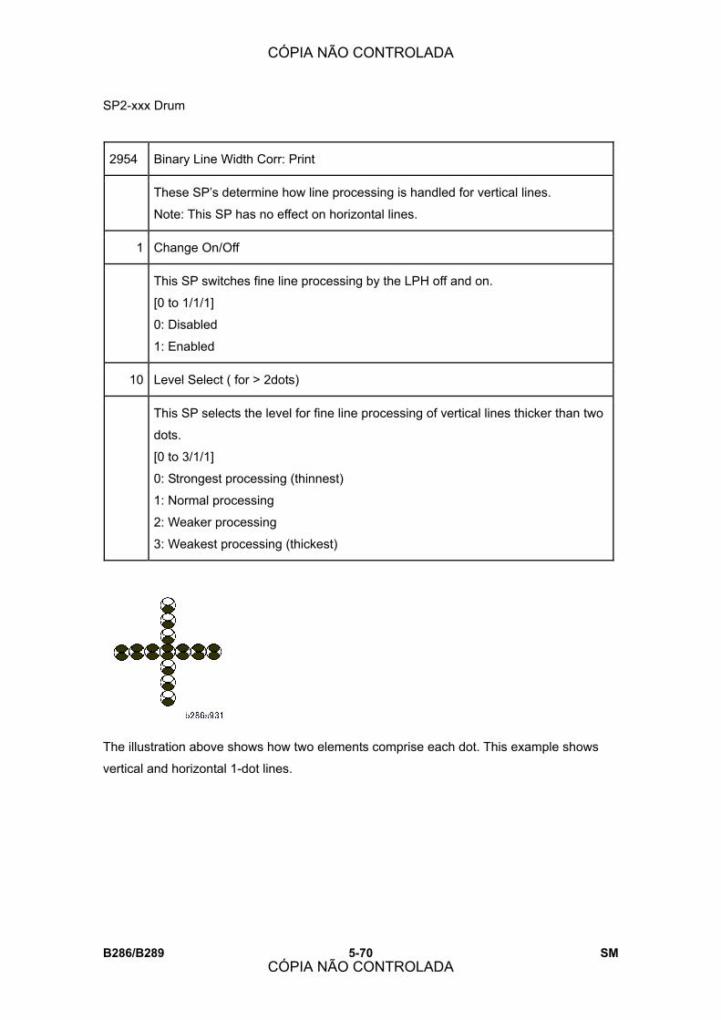
SP2-xxx Drum
B286/B289 5-70 SM
2954 Binary Line Width Corr: Print
These SP�s determine how line processing is handled for vertical lines.
Note: This SP has no effect on horizontal lines.
1 Change On/Off
This SP switches fine line processing by the LPH off and on.
[0 to 1/1/1]
0: Disabled
1: Enabled
10 Level Select ( for > 2dots)
This SP selects the level for fine line processing of vertical lines thicker than two
dots.
[0 to 3/1/1]
0: Strongest processing (thinnest)
1: Normal processing
2: Weaker processing
3: Weakest processing (thickest)
The illustration above shows how two elements comprise each dot. This example shows
vertical and horizontal 1-dot lines.
CÓPIA NÃO CONTROLADA
CÓPIA NÃO CONTROLADA

SP2-xxx Drum
SM 5-71 B286/B289
Serv
ice
Tabl
es
The diagram above illustrates
the patterns for the settings
SP2954-10 (0 to 3) on a 2-dot
vertical line. The settings have
no effect on the horizontal line.
When line thickness more than 2 dots the value selected for SP2954-10 affects only the
outer lines. The diagram above shows �1� selected for SP2954-10. The setting does not
affect the horizontal line.
CÓPIA NÃO CONTROLADA
CÓPIA NÃO CONTROLADA
SP2-xxx Drum
B286/B289 5-72 SM
2959 Display VDB ID
This SP displays the 8-bit data that identifies the FPGA version of the VDB
(Video Drive Board). The VDB controls the signals sent to the LPH.
5.8.1 TEST PATTERN PRINTING
The following procedure will provide information to access various test patterns and to
enable test patterns printing.
1. Open the roll feeder drawer and cut off a sheet manually from a roll. (Turn the manual
feed knob to feed the paper, then push the cutter from side to side to cut.) Close the
roll feeder drawer.
2. Go into the Copy SP. mode.
3. Select SP2902-1, SP2902-2 or SP2902-3 and then select a test pattern (from those
listed in section 5 of the service manual) then press OK.
4. Touch COPY Window. to go to the main screen.
5. On the operation panel, select one of the rolls for paper feed.
6. Put the blank sheet of paper on the original feed tray and feed it into the original feed
unit. The pattern selected prints.
7. Touch SP Mode to return to the SP mode list. Then press 0: None and select OK
before selecting a different set of patterns or exiting out of the SP mode.
CÓPIA NÃO CONTROLADA
CÓPIA NÃO CONTROLADA
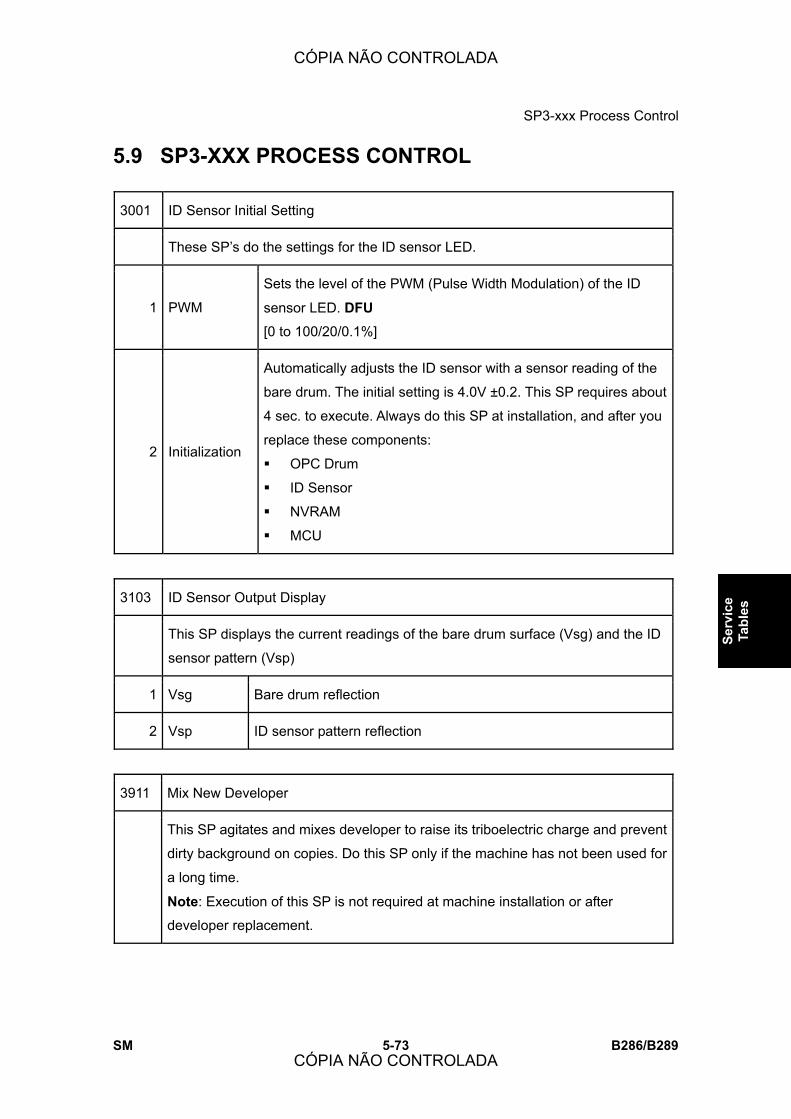
SP3-xxx Process Control
SM 5-73 B286/B289
Serv
ice
Tabl
es
5.9 SP3-XXX PROCESS CONTROL
3001 ID Sensor Initial Setting
These SP�s do the settings for the ID sensor LED.
1 PWM
Sets the level of the PWM (Pulse Width Modulation) of the ID
sensor LED. DFU
[0 to 100/20/0.1%]
2 Initialization
Automatically adjusts the ID sensor with a sensor reading of the
bare drum. The initial setting is 4.0V ±0.2. This SP requires about
4 sec. to execute. Always do this SP at installation, and after you
replace these components:
! OPC Drum
! ID Sensor
! NVRAM
! MCU
3103 ID Sensor Output Display
This SP displays the current readings of the bare drum surface (Vsg) and the ID
sensor pattern (Vsp)
1 Vsg Bare drum reflection
2 Vsp ID sensor pattern reflection
3911 Mix New Developer
This SP agitates and mixes developer to raise its triboelectric charge and prevent
dirty background on copies. Do this SP only if the machine has not been used for
a long time.
Note: Execution of this SP is not required at machine installation or after
developer replacement.
CÓPIA NÃO CONTROLADA
CÓPIA NÃO CONTROLADA
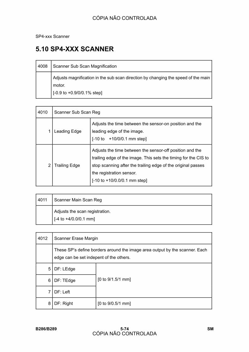
SP4-xxx Scanner
B286/B289 5-74 SM
5.10 SP4-XXX SCANNER
4008 Scanner Sub Scan Magnification
Adjusts magnification in the sub scan direction by changing the speed of the main
motor.
[-0.9 to +0.9/0/0.1% step]
4010 Scanner Sub Scan Reg
1 Leading Edge
Adjusts the time between the sensor-on position and the
leading edge of the image.
[-10 to +10/0/0.1 mm step]
2 Trailing Edge
Adjusts the time between the sensor-off position and the
trailing edge of the image. This sets the timing for the CIS to
stop scanning after the trailing edge of the original passes
the registration sensor.
[-10 to +10/0.0/0.1 mm step]
4011 Scanner Main Scan Reg
Adjusts the scan registration.
[-4 to +4/0.0/0.1 mm]
4012 Scanner Erase Margin
These SP�s define borders around the image area output by the scanner. Each
edge can be set indepent of the others.
5 DF: LEdge
6 DF: TEdge
7 DF: Left
[0 to 9/1.5/1 mm]
8 DF: Right [0 to 9/0.5/1 mm]
CÓPIA NÃO CONTROLADA
CÓPIA NÃO CONTROLADA
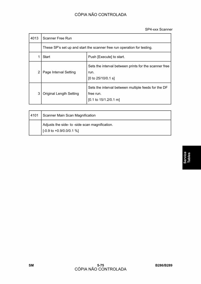
SP4-xxx Scanner
SM 5-75 B286/B289
Serv
ice
Tabl
es
4013 Scanner Free Run
These SP�s set up and start the scanner free run operation for testing.
1 Start Push [Execute] to start.
2 Page Interval Setting
Sets the interval between prints for the scanner free
run.
[0 to 25/10/0.1 s]
3 Original Length Setting
Sets the interval between multiple feeds for the DF
free run.
[0.1 to 15/1.2/0.1 m]
4101 Scanner Main Scan Magnification
Adjusts the side- to -side scan magnification.
[-0.9 to +0.9/0.0/0.1 %]
CÓPIA NÃO CONTROLADA
CÓPIA NÃO CONTROLADA
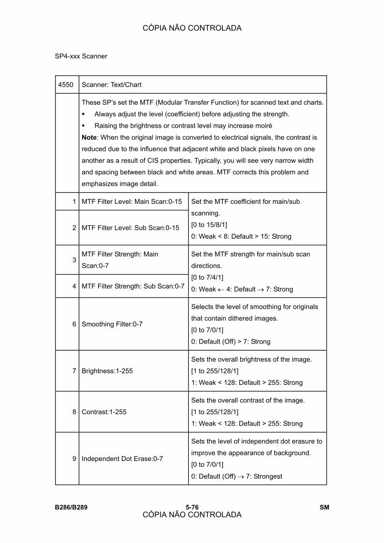
SP4-xxx Scanner
B286/B289 5-76 SM
4550 Scanner: Text/Chart
These SP�s set the MTF (Modular Transfer Function) for scanned text and charts.
! Always adjust the level (coefficient) before adjusting the strength.
! Raising the brightness or contrast level may increase moiré
Note: When the original image is converted to electrical signals, the contrast is
reduced due to the influence that adjacent white and black pixels have on one
another as a result of CIS properties. Typically, you will see very narrow width
and spacing between black and white areas. MTF corrects this problem and
emphasizes image detail.
1 MTF Filter Level: Main Scan:0-15
2 MTF Filter Level: Sub Scan:0-15
Set the MTF coefficient for main/sub
scanning.
[0 to 15/8/1]
0: Weak < 8: Default > 15: Strong
3 MTF Filter Strength: Main
Scan:0-7
4 MTF Filter Strength: Sub Scan:0-7
Set the MTF strength for main/sub scan
directions.
[0 to 7/4/1]
0: Weak ← 4: Default → 7: Strong
6 Smoothing Filter:0-7
Selects the level of smoothing for originals
that contain dithered images.
[0 to 7/0/1]
0: Default (Off) > 7: Strong
7 Brightness:1-255
Sets the overall brightness of the image.
[1 to 255/128/1]
1: Weak < 128: Default > 255: Strong
8 Contrast:1-255
Sets the overall contrast of the image.
[1 to 255/128/1]
1: Weak < 128: Default > 255: Strong
9 Independent Dot Erase:0-7
Sets the level of independent dot erasure to
improve the appearance of background.
[0 to 7/0/1]
0: Default (Off) → 7: Strongest
CÓPIA NÃO CONTROLADA
CÓPIA NÃO CONTROLADA
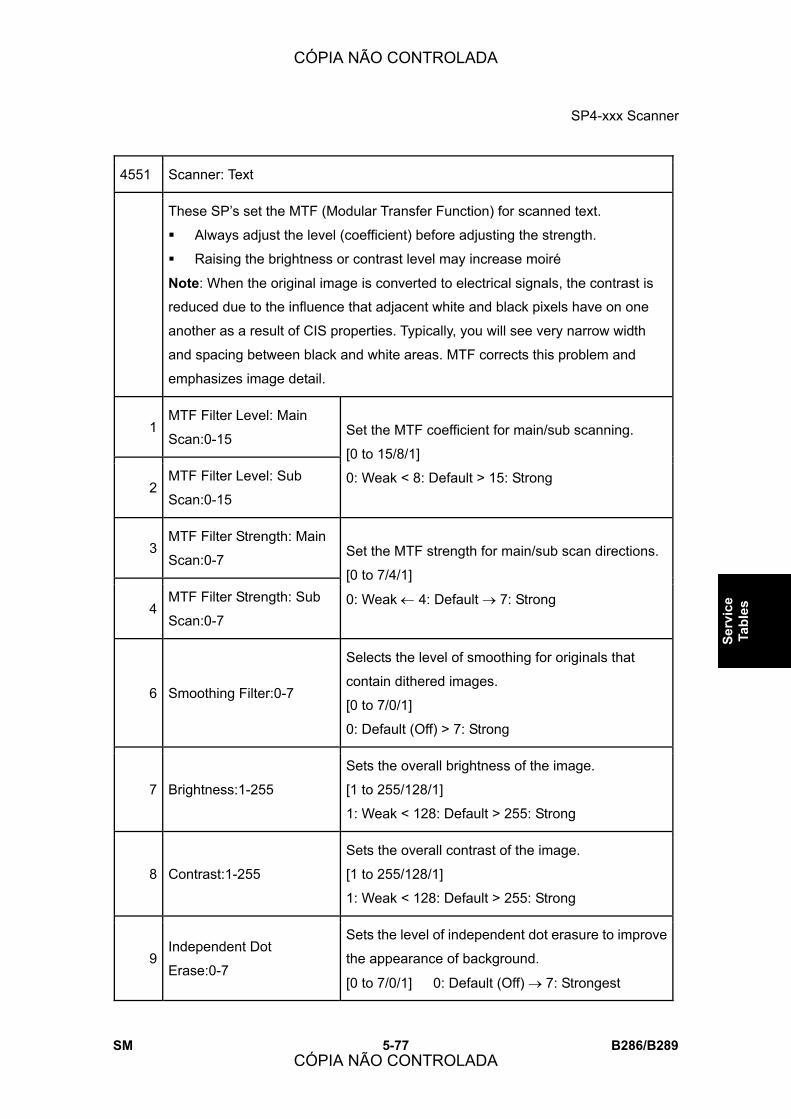
SP4-xxx Scanner
SM 5-77 B286/B289
Serv
ice
Tabl
es
4551 Scanner: Text
These SP�s set the MTF (Modular Transfer Function) for scanned text.
! Always adjust the level (coefficient) before adjusting the strength.
! Raising the brightness or contrast level may increase moiré
Note: When the original image is converted to electrical signals, the contrast is
reduced due to the influence that adjacent white and black pixels have on one
another as a result of CIS properties. Typically, you will see very narrow width
and spacing between black and white areas. MTF corrects this problem and
emphasizes image detail.
1 MTF Filter Level: Main
Scan:0-15
2 MTF Filter Level: Sub
Scan:0-15
Set the MTF coefficient for main/sub scanning.
[0 to 15/8/1]
0: Weak < 8: Default > 15: Strong
3 MTF Filter Strength: Main
Scan:0-7
4 MTF Filter Strength: Sub
Scan:0-7
Set the MTF strength for main/sub scan directions.
[0 to 7/4/1]
0: Weak ← 4: Default → 7: Strong
6 Smoothing Filter:0-7
Selects the level of smoothing for originals that
contain dithered images.
[0 to 7/0/1]
0: Default (Off) > 7: Strong
7 Brightness:1-255
Sets the overall brightness of the image.
[1 to 255/128/1]
1: Weak < 128: Default > 255: Strong
8 Contrast:1-255
Sets the overall contrast of the image.
[1 to 255/128/1]
1: Weak < 128: Default > 255: Strong
9 Independent Dot
Erase:0-7
Sets the level of independent dot erasure to improve
the appearance of background.
[0 to 7/0/1] 0: Default (Off) → 7: Strongest
CÓPIA NÃO CONTROLADA
CÓPIA NÃO CONTROLADA
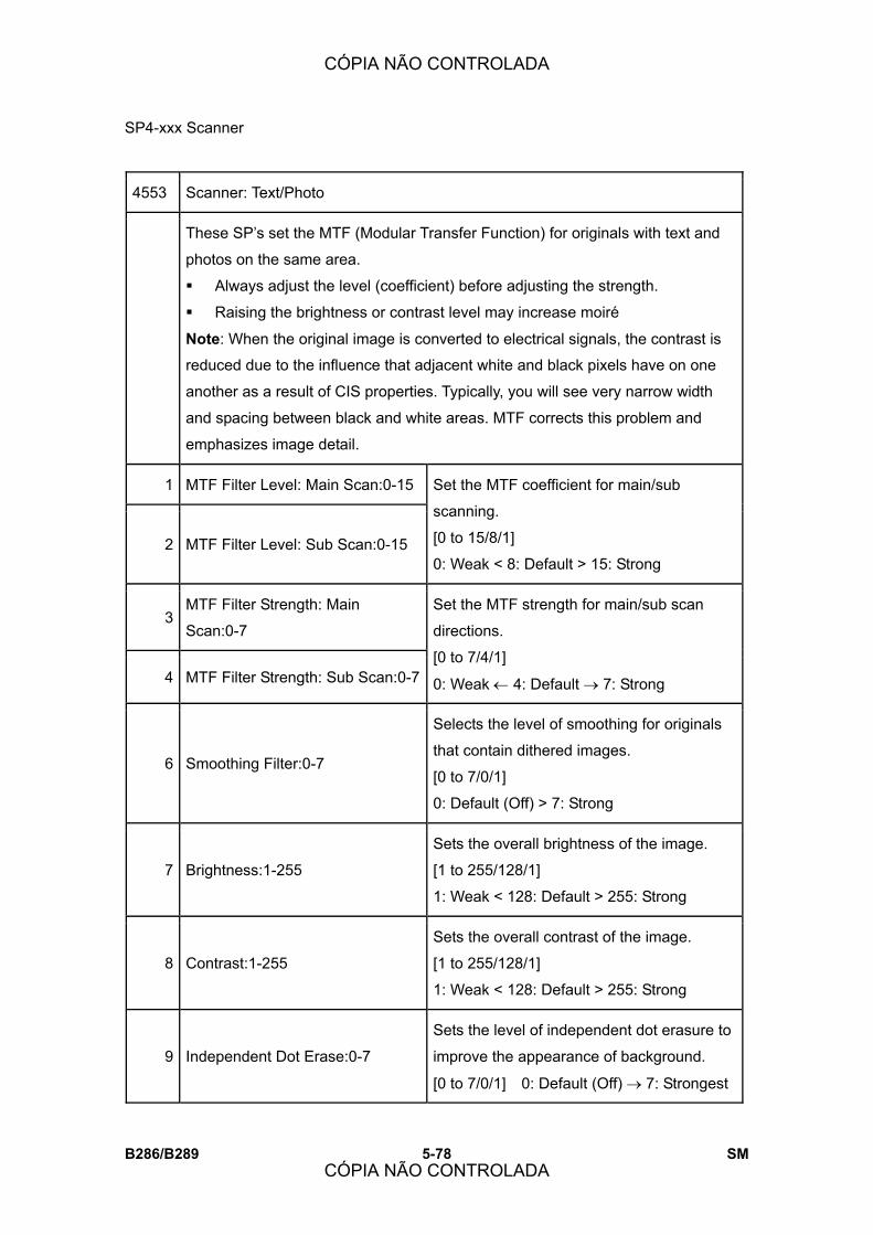
SP4-xxx Scanner
B286/B289 5-78 SM
4553 Scanner: Text/Photo
These SP�s set the MTF (Modular Transfer Function) for originals with text and
photos on the same area.
! Always adjust the level (coefficient) before adjusting the strength.
! Raising the brightness or contrast level may increase moiré
Note: When the original image is converted to electrical signals, the contrast is
reduced due to the influence that adjacent white and black pixels have on one
another as a result of CIS properties. Typically, you will see very narrow width
and spacing between black and white areas. MTF corrects this problem and
emphasizes image detail.
1 MTF Filter Level: Main Scan:0-15
2 MTF Filter Level: Sub Scan:0-15
Set the MTF coefficient for main/sub
scanning.
[0 to 15/8/1]
0: Weak < 8: Default > 15: Strong
3 MTF Filter Strength: Main
Scan:0-7
4 MTF Filter Strength: Sub Scan:0-7
Set the MTF strength for main/sub scan
directions.
[0 to 7/4/1]
0: Weak ← 4: Default → 7: Strong
6 Smoothing Filter:0-7
Selects the level of smoothing for originals
that contain dithered images.
[0 to 7/0/1]
0: Default (Off) > 7: Strong
7 Brightness:1-255
Sets the overall brightness of the image.
[1 to 255/128/1]
1: Weak < 128: Default > 255: Strong
8 Contrast:1-255
Sets the overall contrast of the image.
[1 to 255/128/1]
1: Weak < 128: Default > 255: Strong
9 Independent Dot Erase:0-7
Sets the level of independent dot erasure to
improve the appearance of background.
[0 to 7/0/1] 0: Default (Off) → 7: Strongest
CÓPIA NÃO CONTROLADA
CÓPIA NÃO CONTROLADA

SP4-xxx Scanner
SM 5-79 B286/B289
Serv
ice
Tabl
es
4554 Scanner: Photo
These SP�s set the MTF (Modular Transfer Function) for photo originals.
! Always adjust the level (coefficient) before adjusting the strength.
! Raising the brightness or contrast level may increase moiré
Note: When the original image is converted to electrical signals, the contrast is
reduced due to the influence that adjacent white and black pixels have on one
another as a result of CIS properties. Typically, you will see very narrow width
and spacing between black and white areas. MTF corrects this problem and
emphasizes image detail.
1 MTF Filter Level: Main
Scan:0-15
2 MTF Filter Level: Sub
Scan:0-15
Set the MTF coefficient for main/sub scanning.
[0 to 15/8/1]
0: Weak < 8: Default > 15: Strong
3 MTF Filter Strength: Main
Scan:0-7
4 MTF Filter Strength: Sub
Scan:0-7
Set the MTF strength for main/sub scan
directions.
[0 to 7/4/1]
0: Weak ← 4: Default → 7: Strong
6 Smoothing Filter:0-7
Selects the level of smoothing for originals that
contain dithered images.
[0 to 7/0/1]
0: Default (Off) > 7: Strong
7 Brightness:1-255
Sets the overall brightness of the image.
[1 to 255/128/1]
1: Weak < 128: Default > 255: Strong
8 Contrast:1-255
Sets the overall contrast of the image.
[1 to 255/128/1]
1: Weak < 128: Default > 255: Strong
9 Independent Dot Erase:0-7
Sets the level of independent dot erasure to
improve the appearance of background.
[0 to 7/0/1] 0: Default (Off) → 7: Strongest
CÓPIA NÃO CONTROLADA
CÓPIA NÃO CONTROLADA
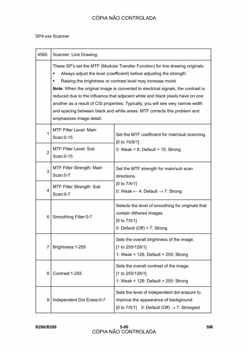
SP4-xxx Scanner
B286/B289 5-80 SM
4565 Scanner: Line Drawing
These SP�s set the MTF (Modular Transfer Function) for line drawing originals.
! Always adjust the level (coefficient) before adjusting the strength.
! Raising the brightness or contrast level may increase moiré
Note: When the original image is converted to electrical signals, the contrast is
reduced due to the influence that adjacent white and black pixels have on one
another as a result of CIS properties. Typically, you will see very narrow width
and spacing between black and white areas. MTF corrects this problem and
emphasizes image detail.
1 MTF Filter Level: Main
Scan:0-15
2 MTF Filter Level: Sub
Scan:0-15
Set the MTF coefficient for main/sub scanning.
[0 to 15/8/1]
0: Weak < 8: Default > 15: Strong
3 MTF Filter Strength: Main
Scan:0-7
4 MTF Filter Strength: Sub
Scan:0-7
Set the MTF strength for main/sub scan
directions.
[0 to 7/4/1]
0: Weak ← 4: Default → 7: Strong
6 Smoothing Filter:0-7
Selects the level of smoothing for originals that
contain dithered images.
[0 to 7/0/1]
0: Default (Off) > 7: Strong
7 Brightness:1-255
Sets the overall brightness of the image.
[1 to 255/128/1]
1: Weak < 128: Default > 255: Strong
8 Contrast:1-255
Sets the overall contrast of the image.
[1 to 255/128/1]
1: Weak < 128: Default > 255: Strong
9 Independent Dot Erase:0-7
Sets the level of independent dot erasure to
improve the appearance of background.
[0 to 7/0/1] 0: Default (Off) → 7: Strongest
CÓPIA NÃO CONTROLADA
CÓPIA NÃO CONTROLADA

SP4-xxx Scanner
SM 5-81 B286/B289
Serv
ice
Tabl
es
4700 Display CIS ASIC ID
This SP displays an 8-bit string that identifies the FPGA version of the SIB board.
4705 CIS Adjustment
1 Flag Display Displays a �0� (not adjusted) or a �1� to indicate whether the
white level adjustment with SP4705-2 has been successful.
2 Start
Input �1� to adjust the standard white level.
Note: Do this SP to correct the problem of uneven density in
copies, especially in filled areas.
4713 CIS White Level Adjustment DFU
These SP�s display the standard white board values after adjustment with
SP4705-2.
1 CIS1
2 CIS2
3 CIS3
4 CIS4
5 CIS5
[0 to 511/0/1]
CÓPIA NÃO CONTROLADA
CÓPIA NÃO CONTROLADA

SP4-xxx Scanner
B286/B289 5-82 SM
4716 CIS White Level Adjustment: Factory DFU
These SP�s display the standard white board values after adjustment at the
factory.
1 CIS1
2 CIS2
3 CIS3
4 CIS4
5 CIS5
[0 to 511/0/1]
Note: If �0� is displayed, this means no adjustment has been
done.
4724 CIS Read Offset Data DFU
These SP codes display the black level read data for visual confirmation at power
on.
1 CIS1 : GE(ven) [0 to 255/0/1]
2 CIS1 : GO(dd)
3 CIS2 : GE(ven)
4 CIS2 : GO(dd)
5 CIS3 : GE(ven)
6 CIS3 : GO(ven)
7 CIS4 : GE(ven)
8 CIS4 : GO(dd)
9 CIS5 : GE(ven)
10 CIS5 : GO(dd)
CÓPIA NÃO CONTROLADA
CÓPIA NÃO CONTROLADA

SP4-xxx Scanner
SM 5-83 B286/B289
Serv
ice
Tabl
es
4732 CIS Gain Adjustment DFU
These SP�s display the gain data of the analog ASIC (EVEN or ODD) from the
CIS after the white level adjustment done immediately after power on. The white
level adjustment sets the peak value (shading data peak) for each channel at
240±2 digits.
1 CIS1 : GE(ven) [0 to 255/0/1]
2 CIS1 : GO(dd)
3 CIS2 : GE(ven)
4 CIS2 : GO(dd)
5 CIS3 : GE(ven)
6 CIS3 : GO(dd)
7 CIS4 : GE(ven)
8 CIS4 : GO(dd)
9 CIS5 : GE(ven)
10 CIS5 : GO(dd)
4735 CIS Read White Level DFU
These SP�s display the peak level of the shading data after white level adjustment
is done immediately after power on.
1 CIS1 : GE(ven) [0 to 255/0/1]
2 CIS1 : GO(dd)
3 CIS2 : GE(ven)
4 CIS2 : GO(dd)
5 CIS3 : GE(ven)
CÓPIA NÃO CONTROLADA
CÓPIA NÃO CONTROLADA

SP4-xxx Scanner
B286/B289 5-84 SM
6 CIS3 : GO(dd)
7 CIS4 : GE(ven)
8 CIS4 : GO(dd)
9 CIS5 : GE(ven)
10 CIS5 : GO(dd)
4741 CIS White Adjust Loop DFU
This SP displays the number of AGC (gain) adjustment loops performed during
white level adjustment.
4745 CIS Adjustment Error Flag DFU
This SP displays the flags of any errors that occur at power on during:
! CIS white level check
! Black level check
! Whte level adjustment
[0 to 1111 1111b]
b0 Black level adjustment timeout (not used)
b1 White level adjustment timeout. The test did not acquire a value after 20
attempts.
b2 White level 1st check error. The acquired value was judged not within
range.
b3 Density adjustment timeout. After 20 attempts a value within range could
not be acquired.
b4 Standard white roller adjustment interrupted. Something interrupted the
adjustment sequence (jam, upper unit opened, etc.)
b5 Standard white roller density adjustment timeout. The original (T6200) was
output before the adjustment completed.
CÓPIA NÃO CONTROLADA
CÓPIA NÃO CONTROLADA

SP4-xxx Scanner
SM 5-85 B286/B289
Serv
ice
Tabl
es
4747 CIS Hard Error Flag DFU
This SP displays the flags of errors that occur during the CIS communication
check done immediately after power on.
b0 Serial output port abnormal. Signal at HIGH level became �1.�
b1 Read failure. Failed to read CIS unit version information.
b2 Write failure. A value was written to the CIS register (AGC_CONT) but it
could not be read.
4762 CIS Gain Adjustment Normally DFU
These SP�s display the gain data of the analog ASIC (EVEN or ODD) from the
CIS after the white level adjustment done immediately after power on. The white
level adjustment sets the peak value (shading data peak) for each channel at
240±2 digits.
1 CIS1 : GE(ven) [0 to 255/0/1]
2 CIS1 : GO(dd)
3 CIS2 : GE(ven)
4 CIS2 : GO(dd)
5 CIS3 : GE(ven)
6 CIS3 : GO(dd)
7 CIS4 : GE(ven)
8 CIS4 : GO(dd)
9 CIS5 : GE(ven)
10 CIS5 : GO(dd)
CÓPIA NÃO CONTROLADA
CÓPIA NÃO CONTROLADA

SP4-xxx Scanner
B286/B289 5-86 SM
4765 CIS Standard White Level Adjustment Normally DFU
These SP�s display the value adjusted for density of the white plate after standard
white plate density adjustment
1 CIS1 [0 to 511/0/1]
2 CIS2
3 CIS3
4 CIS4
5 CIS5
4781 CIS Gain Adjustment at Factory DFU
When SP4705 002 (CIS Adjustment - Start) is executed after SP4705 (CIS
Adjustment) returned a �0� (failure to adjust) and standard white plate density
adjustment ends successfully. The gain value is stored in NVRAM. This SP
retrieves that value and displays it.
1 CIS1 : GE [0 to 255/0/1]
2 CIS1 : GO
3 CIS2 : GE
4 CIS2 : GO
5 CIS3 : GE
6 CIS3 : GO
7 CIS4 : GE
8 CIS4 : GO
9 CIS5 : GE
10 CIS5 : GO
CÓPIA NÃO CONTROLADA
CÓPIA NÃO CONTROLADA

SP4-xxx Scanner
SM 5-87 B286/B289
Serv
ice
Tabl
es
4901 Scan Correction DFU
1 Shading Correction: AEREF
Setting
Displays the AEREF value used to supplement
shading processing.
[0 to 63/0/1]
2 Shading Correction: Shading
Data Output
Outputs the shading data used during
supplemental shading processing of scanned
image data.
[0 to 1/0/1]
0: Scanned image after shading processing
(normal)
1: Shading data
3 Digital AE: AEREF Setting
Changes the AEREF value used during digital
A/E processing of the scanned image.
[-63 to +63/0/1]
4 Digital AE: Low Limit
Provides the boundary values to the digital A/E
processing address for the scanned image data.
[0 to 255/41/1]
5 Digital AE: Start Position
Defines the start position for digital A/E
processing of the scanned image data.
[0.5 to 10.0/5.0/0.1 mm]
4903 Image Quality Adj.
Use this if density is not equal in shaded areas of the copy. The change from high
to low density areas in shaded areas must be smooth. Do these SP adjustments
if you see �false outlines� in shaded areas of the copy.
! To increase the effect, use a higher setting.
! To decrease the effect, use a lower setting.
! The higher settings can make text look better, but can also decrease the
quality of the image.
MTF Filter Settings
1 Text (25.0-55.0%)
CÓPIA NÃO CONTROLADA
CÓPIA NÃO CONTROLADA
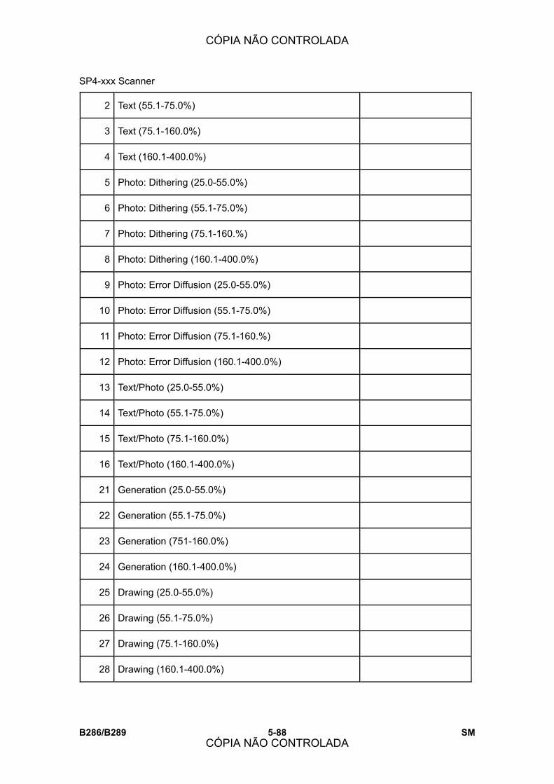
SP4-xxx Scanner
B286/B289 5-88 SM
2 Text (55.1-75.0%)
3 Text (75.1-160.0%)
4 Text (160.1-400.0%)
5 Photo: Dithering (25.0-55.0%)
6 Photo: Dithering (55.1-75.0%)
7 Photo: Dithering (75.1-160.%)
8 Photo: Dithering (160.1-400.0%)
9 Photo: Error Diffusion (25.0-55.0%)
10 Photo: Error Diffusion (55.1-75.0%)
11 Photo: Error Diffusion (75.1-160.%)
12 Photo: Error Diffusion (160.1-400.0%)
13 Text/Photo (25.0-55.0%)
14 Text/Photo (55.1-75.0%)
15 Text/Photo (75.1-160.0%)
16 Text/Photo (160.1-400.0%)
21 Generation (25.0-55.0%)
22 Generation (55.1-75.0%)
23 Generation (751-160.0%)
24 Generation (160.1-400.0%)
25 Drawing (25.0-55.0%)
26 Drawing (55.1-75.0%)
27 Drawing (75.1-160.0%)
28 Drawing (160.1-400.0%)
CÓPIA NÃO CONTROLADA
CÓPIA NÃO CONTROLADA

SP4-xxx Scanner
SM 5-89 B286/B289
Serv
ice
Tabl
es
29 Patched Original (25.0-55.0%)
30 Patched Original (55.1-75.0%)
31 Patched Original (75.1-160.0%)
32 Patched Original (160.1-400.0%)
33 Blue Line (25.0-55.0%)
34 Blue Line (55.1-75.0%)
35 Blue Line (75.1-160.0%)
36 Blue Line (160.1-400.0%)
Independent Dot Erase
60 Independent Dot Erase: Text
61 Independent Dot Erase: Photo
62 Independent Dot Erase: Text/Photo
64 Independent Dot Erase: Generation
65 Independent Dot Erase: Drawing
66 Independent Dot Erase: Patched Original
67 Independent Dot Erase: Blue Line
Background Erase
70 Background Erase: Text
71 Background Erase: Photo
72 Background Erase: Text/Photo
74 Background Erase: Generation
75 Background Erase: Drawing
76 Background Erase: Patched Original
CÓPIA NÃO CONTROLADA
CÓPIA NÃO CONTROLADA

SP4-xxx Scanner
B286/B289 5-90 SM
77 Background Erase: Blue Line
Line Width Correction
80 Line Width Corr: Text: Mode Select
81 Line Width Corr: Text: Main Scan
82 Line Width Corr: Text: Sub Scan
83 Line Width Corr: Photo: Mode Select
84 Line Width Corr: Photo: Main Scan
85 Line Width Corr: Photo: Sub Scan
86 Line Width Corr: Text/Photo: Mode Select
87 Line Width Corr: Text/Photo: Main Scan
88 Line Width Corr: Text/Photo: Sub Scan
95 Line Width Corr: Drawing: Mode Select
96 Line Width Corr: Drawing: Main Scan
97 Line Width Corr: Drawing: Sub Scan
98 Line Width Corr: Patched Original: Mode Select
99 Line Width Corr: Patched Original: Main Scan
100 Line Width Corr: Patched Original: Sub Scan
101 Line Width Corr: Blue Line: Mode Select
102 Line Width Corr: Blue Line: Main Scan
103 Line Width Corr: Blue Line: Sub Scan
CÓPIA NÃO CONTROLADA
CÓPIA NÃO CONTROLADA

SP4-xxx Scanner
SM 5-91 B286/B289
Serv
ice
Tabl
es
4904 Image Process Setting
These SP�s set up image processing for each mode.
! The smoothing level filters remove false outlines.
! Line width correction corrects thin vertical lines.
2 Process Select: Photo
This SP sets the matrix that is used for dithering in the Photo Mode.
[1 to 3/0/1]
0: 8 x 8 dithering
1: 6 x 6 dithering
2: 4 x 4 dithering
3: Error diffusion
3 Density level: Patched Original [0 to 8/2/1]
10 Smoothing Filter Level: Text [0 to 3/1/1]
11 Smoothing Filter Level: Photo [0 to 3/2/1]
12 Smoothing Filter Level: Text/Photo
14 Smoothing Filter Level: Generation
15 Smoothing Filter Level: Drawing
[0 to 3/1/1]
16 Smoothing Filter Level: Patched Original
17 Smoothing Filter Level: Blue Line
CÓPIA NÃO CONTROLADA
CÓPIA NÃO CONTROLADA

SP4-xxx Scanner
B286/B289 5-92 SM
4909 Image Processing Through
These SP�s check the operation of the scan and print processing modules on the
IPU board.
IPU Scan Image Module
This SP checks the operations of the scanned image processing modules on the
IPU board.
(7) 0000 0000 (0)
0: Shading correction 4: Independent dot erase
1: Scanner gamma 5: Gamma (scan path)
2: Filter 6: Gradation processing (scan path)
1
3: Line width correction 7: Scan mask
IPU Plotter Image Module
This SP checks the operations of the print image processing modules on the IPU
board.
(7) 0000 0000 (0) 2
0: Print magnification
1: Gamma
2: Gradation processing
4: Print mask
CÓPIA NÃO CONTROLADA
CÓPIA NÃO CONTROLADA

SP4-xxx Scanner
SM 5-93 B286/B289
Serv
ice
Tabl
es
4961 Original Adjustment
1 Synchro-cut
Adjustment 210mm
Adjusts the synchro-cut position.
[-9.9 to +9.9/0.0/0.1 mm ]
Use the 210-mm position in the sample to check the
difference. This setting is used to calculate the motor clock
count for adjusting the difference.
2 Synchro-cut
Adjustment 1000mm
Adjusts the synchro-cut position.
[-9.9 to +9.9/0.0/0.1 mm step]
Use the 1000-mm position in the sample to check the
difference. This setting is used to calculate the motor clock
count for adjusting the difference.
3 Original Length
Display Displays the original length.
4965 Original Speed:LEdge
The original feed roller tries to adjust for slippage of the feed rollers to allow the
machine measure the length of the original accurately. The diameter of the feed
roller (32 ±0.05) differs slightly from the diameter of the exit roller (32 ±0.05). The
slightly higher speed of the exit roller could cause the original to feed faster than
usual, and cause distortion of the image at the joints of the CIS. Use this SP to
lower the speed of the original to correct this problem if image distortion at the
CIS joints occurs.
When to Use This SP
! Adjust this SP if you see image distortion after replacing the original feed
roller or exit roller.
! You may also need to adjust this SP if you see image distortion after CIS
adjustments with SP4872.
For more about how to use SP4865, please refer to �Replacements and
Adjustments � > �Scanner�, �Original Feed Unit Rollers� for how to use SP 4965.
[-1.0 to 0.0/ -0.2 /0.1]
CÓPIA NÃO CONTROLADA
CÓPIA NÃO CONTROLADA

SP4-xxx Scanner
B286/B289 5-94 SM
4972 CIS Joint Adjustment
These SP�s correct the alignment the image scanned by the CIS. For more, see
section 3.112 (CIS Adjustment with SP Code)
1 CIS1-2 Main Scan
2 CIS2-3 Main Scan
3 CIS3-4 Main Scan
4 CIS4-5 Main Scan
11 CIS1-2 Sub Scan
12 CIS2-3 Sub Scan
13 CIS3-4 Sub Scan
14 CIS4-5 Sub Scan
[-127 to +127/0/1]
4973 CIS Scan Setting
This SP disables and enables correction of the alignment of the CIS elements
with SP4972. For more, see SP Adjustments.
[0 to 1/0/1]
0: Correction allowed
1: Correction not allowed
CÓPIA NÃO CONTROLADA
CÓPIA NÃO CONTROLADA

SP4-xxx Scanner
SM 5-95 B286/B289
Serv
ice
Tabl
es
4974 CIS Power Corr DFU
These SP�s adjust the level of current to the CIS elements. Adjusting these
settings affect LED control. Adjustments can be done separately for Red, Green,
and Blue.
1 R
Corrects the current level for Red. When set to �0�, the LED is off. When
set to any value other than �0�, the LED lights and Red can be adjusted.
[+127 to -127/0/1]
11 G
Corrects the current level for Green. This SP is adjusted to change when
the scanning with the default settings does not achieve satisfactory
results.
[+127 to -127/0/1]
21 B
Corrects the current level for Blue. When set to �0�, the LED is off. When
set to any value other than �0�, the LED lights and Blue can be adjusted.
[+127 to -127/0/1]
4975 Original Edge Hold
This SP determines whether the machine stops and holds the original after the
original is fed so that it does not fall.
[0 to 1/0/1]
*0: Disable, 1: Enable
CÓPIA NÃO CONTROLADA
CÓPIA NÃO CONTROLADA
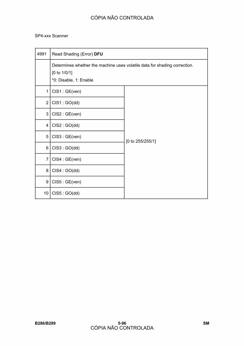
SP4-xxx Scanner
B286/B289 5-96 SM
4991 Read Shading (Error) DFU
Determines whether the machine uses volatile data for shading correction.
[0 to 1/0/1]
*0: Disable, 1: Enable
1 CIS1 : GE(ven)
2 CIS1 : GO(dd)
3 CIS2 : GE(ven)
4 CIS2 : GO(dd)
5 CIS3 : GE(ven)
6 CIS3 : GO(dd)
7 CIS4 : GE(ven)
8 CIS4 : GO(dd)
9 CIS5 : GE(ven)
10 CIS5 : GO(dd)
[0 to 255/255/1]
CÓPIA NÃO CONTROLADA
CÓPIA NÃO CONTROLADA
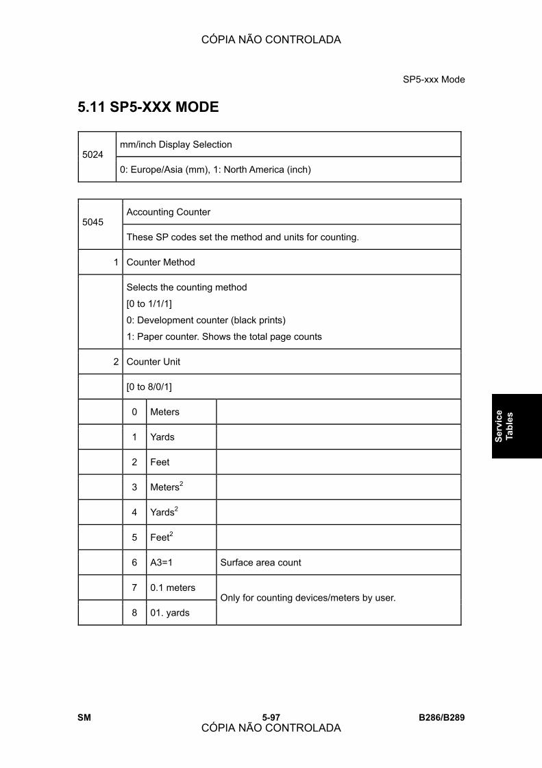
SP5-xxx Mode
SM 5-97 B286/B289
Serv
ice
Tabl
es
5.11 SP5-XXX MODE
mm/inch Display Selection 5024
0: Europe/Asia (mm), 1: North America (inch)
Accounting Counter 5045
These SP codes set the method and units for counting.
1 Counter Method
Selects the counting method
[0 to 1/1/1]
0: Development counter (black prints)
1: Paper counter. Shows the total page counts
2 Counter Unit
[0 to 8/0/1]
0 Meters
1 Yards
2 Feet
3 Meters2
4 Yards2
5 Feet2
6 A3=1 Surface area count
7 0.1 meters
8 01. yards Only for counting devices/meters by user.
CÓPIA NÃO CONTROLADA
CÓPIA NÃO CONTROLADA
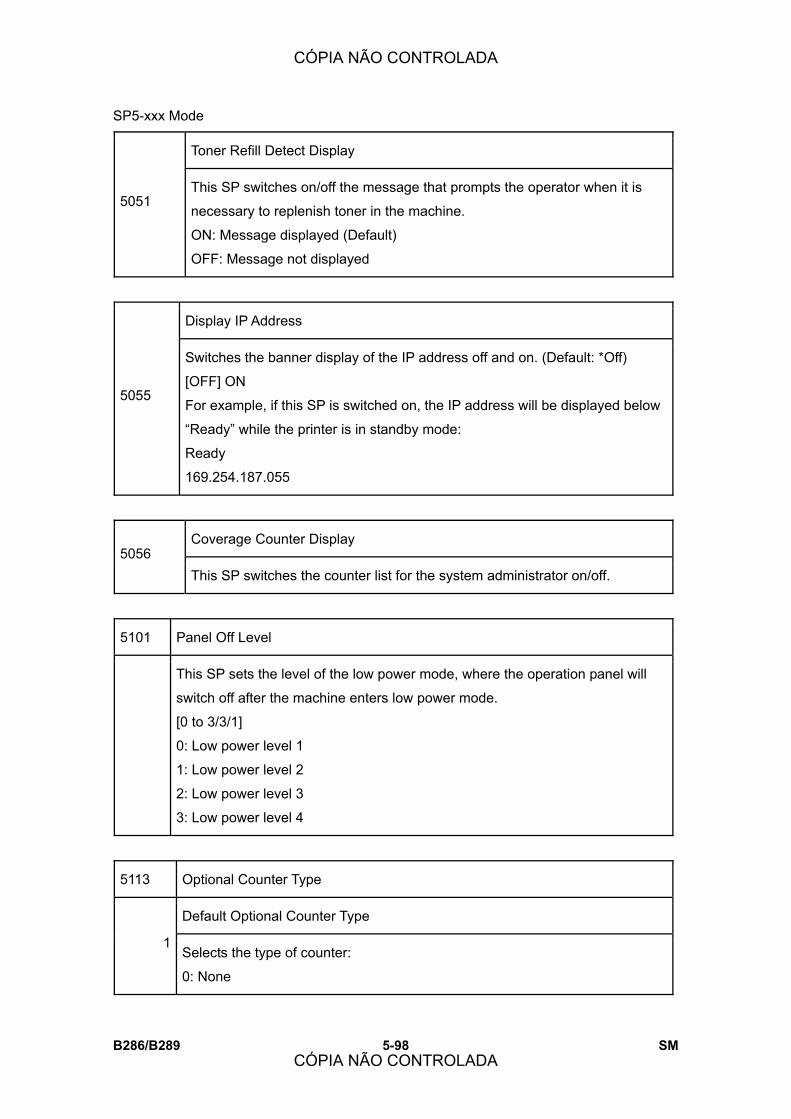
SP5-xxx Mode
B286/B289 5-98 SM
Toner Refill Detect Display
5051 This SP switches on/off the message that prompts the operator when it is
necessary to replenish toner in the machine.
ON: Message displayed (Default)
OFF: Message not displayed
Display IP Address
5055
Switches the banner display of the IP address off and on. (Default: *Off)
[OFF] ON
For example, if this SP is switched on, the IP address will be displayed below
�Ready� while the printer is in standby mode:
Ready
169.254.187.055
Coverage Counter Display 5056
This SP switches the counter list for the system administrator on/off.
5101 Panel Off Level
This SP sets the level of the low power mode, where the operation panel will
switch off after the machine enters low power mode.
[0 to 3/3/1]
0: Low power level 1
1: Low power level 2
2: Low power level 3
3: Low power level 4
5113 Optional Counter Type
Default Optional Counter Type
1 Selects the type of counter:
0: None
CÓPIA NÃO CONTROLADA
CÓPIA NÃO CONTROLADA

SP5-xxx Mode
SM 5-99 B286/B289
Serv
ice
Tabl
es
1: Key Card (RK3, 4) Japan Only
2: Key Card Down
3: Pre-paid Card
4: Coin Rack
5: MF Key Card
11: Exp Key Card (Add)
12: Exp Key Card (Deduct)
External Optional Counter Type
2
Enables the SDK application. This lets you select a number for the external
device for user access control.
Note: �SDK� refers to software on an SD card.
[0 to 3/1]
0: None
1: Expansion Device 1
2: Expansion Device 2
3: Expansion Device 3
5114 Optional Counter I/F
This SP code enables the interface for an optional counting device.
[0 to 8/0/1]
Important Note: Only settings that can be enabled for machines outside Japan
are listed here.
0: Disabled
1: Key Cards (RK2, 3, 4)
2: Decrementing keycard
11: Incrementing key cards for use outside Japan
12: Decrementing key cards for use outside Japan
CÓPIA NÃO CONTROLADA
CÓPIA NÃO CONTROLADA
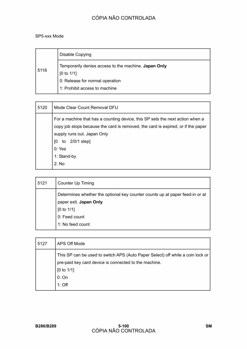
SP5-xxx Mode
B286/B289 5-100 SM
Disable Copying
5118 Temporarily denies access to the machine. Japan Only
[0 to 1/1]
0: Release for normal operation
1: Prohibit access to machine
5120 Mode Clear Count Removal DFU
For a machine that has a counting device, this SP sets the next action when a
copy job stops because the card is removed, the card is expired, or if the paper
supply runs out. Japan Only
[0 to 2/0/1 step]
0: Yes
1: Stand-by
2: No
5121 Counter Up Timing
Determines whether the optional key counter counts up at paper feed-in or at
paper exit. Japan Only
[0 to 1/1]
0: Feed count
1: No feed count
5127 APS Off Mode
This SP can be used to switch APS (Auto Paper Select) off while a coin lock or
pre-paid key card device is connected to the machine.
[0 to 1/1]
0: On
1: Off
CÓPIA NÃO CONTROLADA
CÓPIA NÃO CONTROLADA

SP5-xxx Mode
SM 5-101 B286/B289
Serv
ice
Tabl
es
5162 App. Switch Method
Determines if the application screen changes with a hardware switch or a
software switch.
[0 to 1/1]
0: Soft Key Set
1: Hard Key Set
5169 CE Login
This SP enables and disables the CE log in mode. With this SP enabled, the
machine is in the CE (Customer Engineer/Service Technician) login mode.
In the CE login mode:
! The machine power can be turned off and on in the SP mode, and it will
remain in the SP mode after power is restored.
! This SP is automatically reset to �0� (disabled) after the service technician
closes the SP mode with the [Exit] soft button or after the log out timer
expires.
Note: The Auto Logout Timer is in the �System Settings� of UserTools.
*0: Disable, 1: Enable
0: CE login mode disabled.
1: CE login mode enabled.
5180 Charge Counter Method Japan Only
This SP codes sets the charge counter method.
[0 to 1/1/1]
0: Count number of sheets by paper size
1: Count frequency by paper size
5188 Copy NV Version DFU
This SP displays the NVRAM version to determine whether the NVRAM has
been initialized. Used during debugging.
CÓPIA NÃO CONTROLADA
CÓPIA NÃO CONTROLADA

SP5-xxx Mode
B286/B289 5-102 SM
5212 Page Numbering Not Used
Set Time DFU
5302
Sets the time clock for the local time. This setting is done at the factory before
delivery. The setting is GMT expressed in minutes.
[�1440 to 1440/1 min.]
JA: +540 (Tokyo)
NA: -300 (NY)
EU: +6- (Paris)
CH: +480 (Peking)
TW: +480 (Taipei)
AS: +480 (Hong Kong)
Summer Time
Lets you set the machine to adjust its date and time automatically with the
change to Daylight Savings time in the spring, and back to normal time in the
fall. This SP lets you set these items:
! Day and time to go forward automatically in April
! Day and time to go back automatically in October
! Set the length of time to go forward and back automatically
! The settings for 2 and 3 are done with 8-digit numbers
Digits Meaning
1st, 2nd
Month. 4: April, 10: October (for months 1 to 9, the first digit of 0
cannot be input, so the eight-digit setting for 2 or 3 becomes a
seven-digit setting)
3rd Day of the week. 0: Sunday, 1: Monday
4th
The number of the week for the day selected at the 3rd digit. If �0� is
selected for �Sunday�, for example, and the selected Sunday is the
start of the 2nd week, then input a �2� for this digit.
5307
5th, 6th The time when the change occurs (24-hour as hex code).
Example: 00:00 (Midnight) = 00, 01:00 (1 a.m.) = 01, and so on.
CÓPIA NÃO CONTROLADA
CÓPIA NÃO CONTROLADA
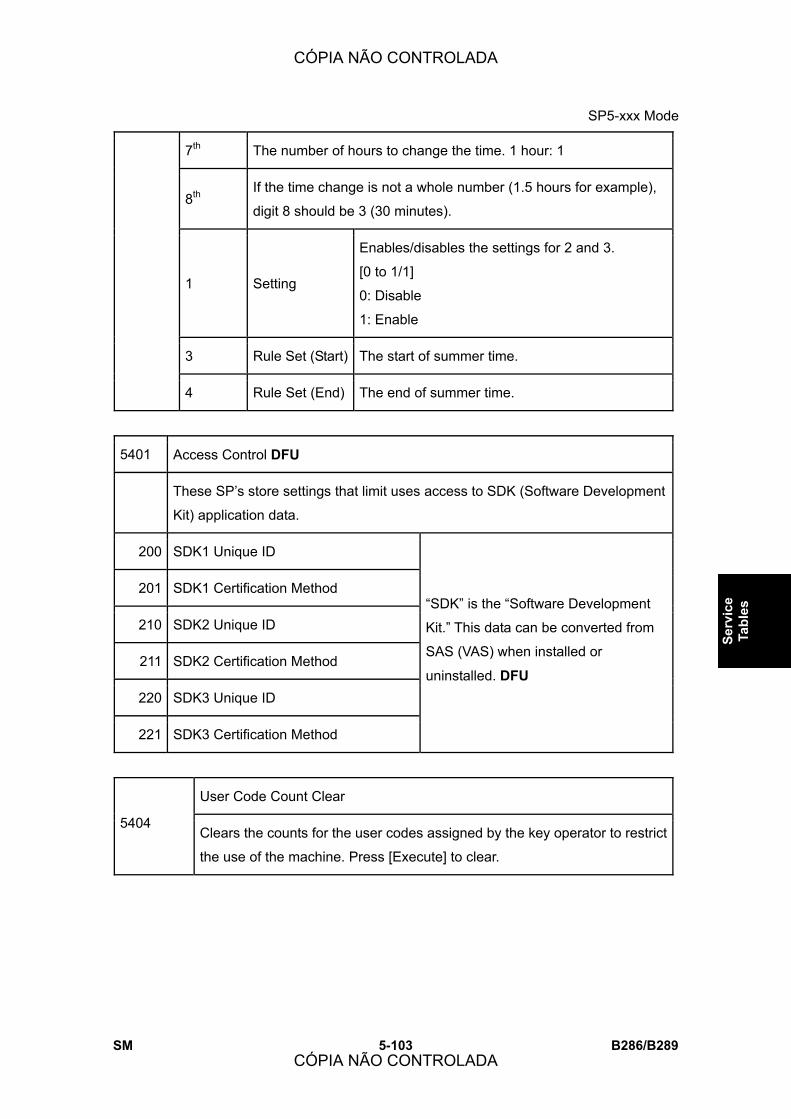
SP5-xxx Mode
SM 5-103 B286/B289
Serv
ice
Tabl
es
7th The number of hours to change the time. 1 hour: 1
8th If the time change is not a whole number (1.5 hours for example),
digit 8 should be 3 (30 minutes).
1 Setting
Enables/disables the settings for 2 and 3.
[0 to 1/1]
0: Disable
1: Enable
3 Rule Set (Start) The start of summer time.
4 Rule Set (End) The end of summer time.
5401 Access Control DFU
These SP�s store settings that limit uses access to SDK (Software Development
Kit) application data.
200 SDK1 Unique ID
201 SDK1 Certification Method
210 SDK2 Unique ID
211 SDK2 Certification Method
220 SDK3 Unique ID
221 SDK3 Certification Method
�SDK� is the �Software Development
Kit.� This data can be converted from
SAS (VAS) when installed or
uninstalled. DFU
User Code Count Clear
5404 Clears the counts for the user codes assigned by the key operator to restrict
the use of the machine. Press [Execute] to clear.
CÓPIA NÃO CONTROLADA
CÓPIA NÃO CONTROLADA
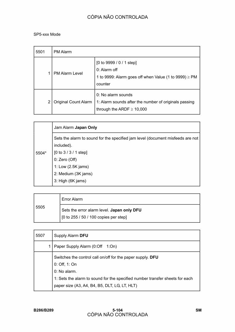
SP5-xxx Mode
B286/B289 5-104 SM
5501 PM Alarm
1 PM Alarm Level
[0 to 9999 / 0 / 1 step]
0: Alarm off
1 to 9999: Alarm goes off when Value (1 to 9999) ≥ PM
counter
2 Original Count Alarm
0: No alarm sounds
1: Alarm sounds after the number of originals passing
through the ARDF ≥ 10,000
Jam Alarm Japan Only
5504*
Sets the alarm to sound for the specified jam level (document misfeeds are not
included).
[0 to 3 / 3 / 1 step]
0: Zero (Off)
1: Low (2.5K jams)
2: Medium (3K jams)
3: High (6K jams)
Error Alarm
5505 Sets the error alarm level. Japan only DFU
[0 to 255 / 50 / 100 copies per step]
5507 Supply Alarm DFU
1 Paper Supply Alarm (0:Off 1:On)
Switches the control call on/off for the paper supply. DFU
0: Off, 1: On
0: No alarm.
1: Sets the alarm to sound for the specified number transfer sheets for each
paper size (A3, A4, B4, B5, DLT, LG, LT, HLT)
CÓPIA NÃO CONTROLADA
CÓPIA NÃO CONTROLADA
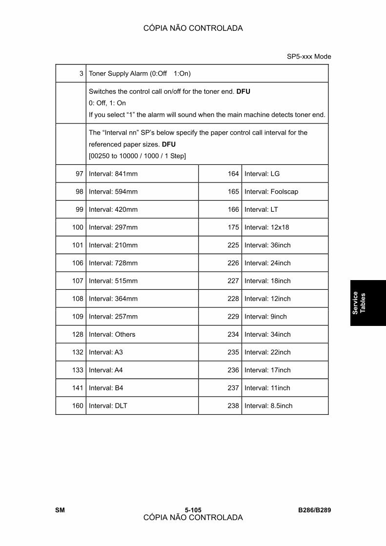
SP5-xxx Mode
SM 5-105 B286/B289
Serv
ice
Tabl
es
3 Toner Supply Alarm (0:Off 1:On)
Switches the control call on/off for the toner end. DFU
0: Off, 1: On
If you select �1� the alarm will sound when the main machine detects toner end.
The �Interval nn� SP�s below specify the paper control call interval for the
referenced paper sizes. DFU
[00250 to 10000 / 1000 / 1 Step]
97 Interval: 841mm 164 Interval: LG
98 Interval: 594mm 165 Interval: Foolscap
99 Interval: 420mm 166 Interval: LT
100 Interval: 297mm 175 Interval: 12x18
101 Interval: 210mm 225 Interval: 36inch
106 Interval: 728mm 226 Interval: 24inch
107 Interval: 515mm 227 Interval: 18inch
108 Interval: 364mm 228 Interval: 12inch
109 Interval: 257mm 229 Interval: 9inch
128 Interval: Others 234 Interval: 34inch
132 Interval: A3 235 Interval: 22inch
133 Interval: A4 236 Interval: 17inch
141 Interval: B4 237 Interval: 11inch
160 Interval: DLT 238 Interval: 8.5inch
CÓPIA NÃO CONTROLADA
CÓPIA NÃO CONTROLADA
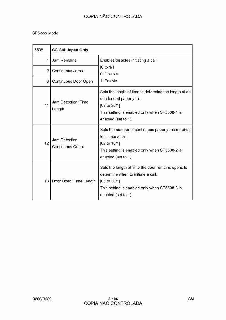
SP5-xxx Mode
B286/B289 5-106 SM
5508 CC Call Japan Only
1 Jam Remains
2 Continuous Jams
3 Continuous Door Open
Enables/disables initiating a call.
[0 to 1/1]
0: Disable
1: Enable
11 Jam Detection: Time
Length
Sets the length of time to determine the length of an
unattended paper jam.
[03 to 30/1]
This setting is enabled only when SP5508-1 is
enabled (set to 1).
12 Jam Detection
Continuous Count
Sets the number of continuous paper jams required
to initiate a call.
[02 to 10/1]
This setting is enabled only when SP5508-2 is
enabled (set to 1).
13 Door Open: Time Length
Sets the length of time the door remains opens to
determine when to initiate a call.
[03 to 30/1]
This setting is enabled only when SP5508-3 is
enabled (set to 1).
CÓPIA NÃO CONTROLADA
CÓPIA NÃO CONTROLADA

SP5-xxx Mode
SM 5-107 B286/B289
Serv
ice
Tabl
es
5515 SC Call
1 Determines whether an SC call is issued when an SC error occurs while either
CSS (Japan) or @Remote is enabled:
[0 to 1/1/1]
1: An SC call is issued when an SC error occurs.
0: An SC call is not issued when an SC error occurs.
2 Service Parts Near End Call
3 Service Parts End Call
4 User Call
6 Communication Test Call
7 Machine Information Notice
8 Alarm Notice
10 Supply Automatic Ordering Call
11 Supply Management Report Call
12 Jam/Door Open Call
5792 MCS Debug SW DFU
5793 ECS Debug SW DFU
CÓPIA NÃO CONTROLADA
CÓPIA NÃO CONTROLADA
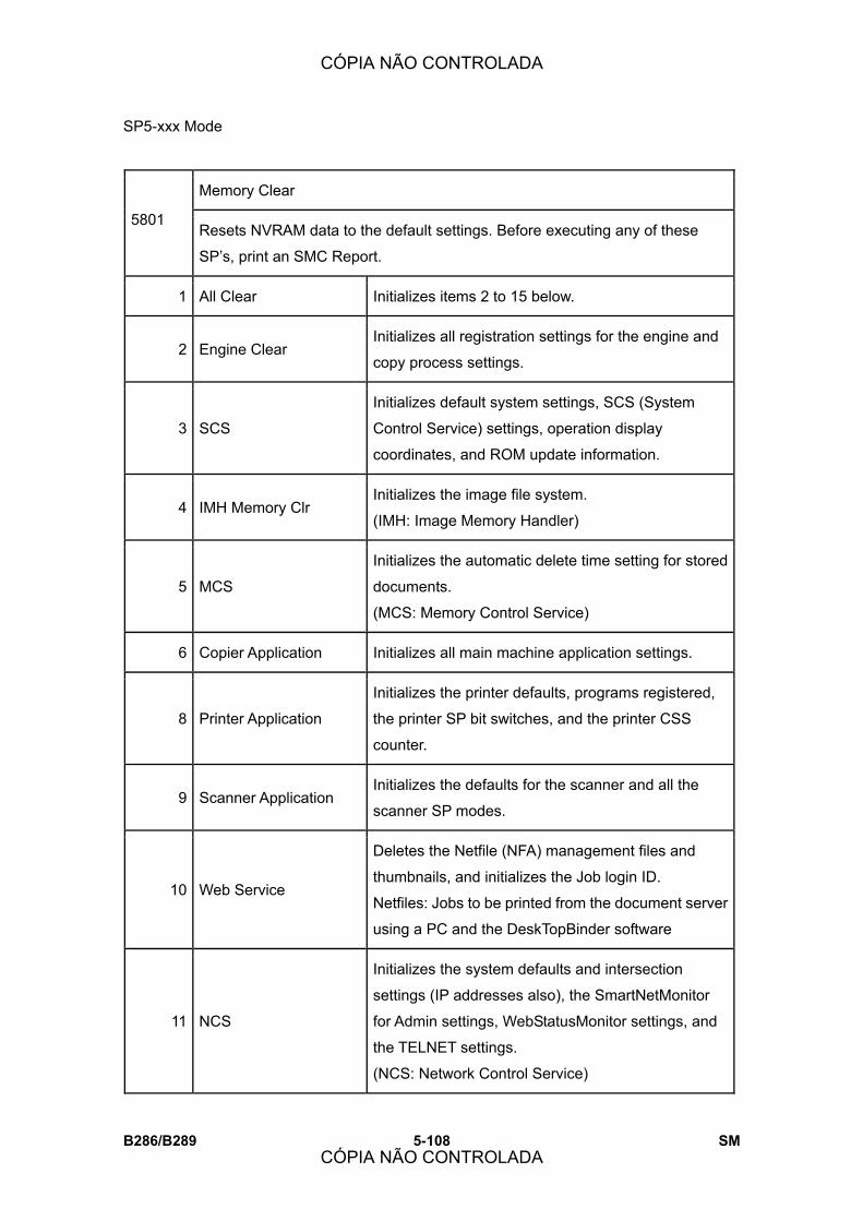
SP5-xxx Mode
B286/B289 5-108 SM
Memory Clear
5801 Resets NVRAM data to the default settings. Before executing any of these
SP�s, print an SMC Report.
1 All Clear Initializes items 2 to 15 below.
2 Engine Clear Initializes all registration settings for the engine and
copy process settings.
3 SCS
Initializes default system settings, SCS (System
Control Service) settings, operation display
coordinates, and ROM update information.
4 IMH Memory Clr Initializes the image file system.
(IMH: Image Memory Handler)
5 MCS
Initializes the automatic delete time setting for stored
documents.
(MCS: Memory Control Service)
6 Copier Application Initializes all main machine application settings.
8 Printer Application
Initializes the printer defaults, programs registered,
the printer SP bit switches, and the printer CSS
counter.
9 Scanner Application Initializes the defaults for the scanner and all the
scanner SP modes.
10 Web Service
Deletes the Netfile (NFA) management files and
thumbnails, and initializes the Job login ID.
Netfiles: Jobs to be printed from the document server
using a PC and the DeskTopBinder software
11 NCS
Initializes the system defaults and intersection
settings (IP addresses also), the SmartNetMonitor
for Admin settings, WebStatusMonitor settings, and
the TELNET settings.
(NCS: Network Control Service)
CÓPIA NÃO CONTROLADA
CÓPIA NÃO CONTROLADA

SP5-xxx Mode
SM 5-109 B286/B289
Serv
ice
Tabl
es
14 Clear DCS Setting Initializes the DCS (Delivery Control Service)
settings.
15 Clear UCS Setting Initializes the UCS (User Information Control
Service) settings.
16 MIRS Setting Initializes the MIRS (Machine Information Report
Service) settings.
17 CCS Initializes the CCS (Certification and Charge-control
Service) settings.
18 SRM Memory Clr Initializes information in non-volatile RAM.
19 LCS Memory Clr Initializes information in non-volatile RAM.
5802 Printer Free Run
Does a free run in the mode specified on the operation panel.
Push On or Off to switch on or off.
5803 Input Check
Displays the signals received from switches and sensors.
1 Roll Tray 8 Unit Set Detection
2 1st & 2nd Roll 9 Door Open/Motor Lock
3 3rd & 4th Roll 10 Others
4 Cassette Tray 11 Dip Switch 1
5 1st Cassette 12 Original Size Sensor 1
6 2nd cassette 13 Original Size Sensor 2
7 Paper Path Sensors 14 Original Feed unit
CÓPIA NÃO CONTROLADA
CÓPIA NÃO CONTROLADA
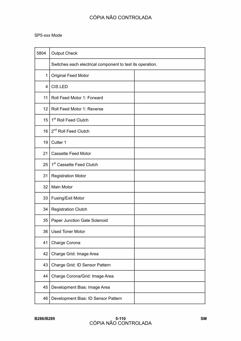
SP5-xxx Mode
B286/B289 5-110 SM
5804 Output Check
Switches each electrical component to test its operation.
1 Original Feed Motor
4 CIS LED
11 Roll Feed Motor 1: Forward
12 Roll Feed Motor 1: Reverse
15 1st Roll Feed Clutch
16 2nd Roll Feed Clutch
19 Cutter 1
21 Cassette Feed Motor
25 1st Cassette Feed Clutch
31 Registration Motor
32 Main Motor
33 Fusing/Exit Motor
34 Registration Clutch
35 Paper Junction Gate Solenoid
36 Used Toner Motor
41 Charge Corona
42 Charge Grid: Image Area
43 Charge Grid: ID Sensor Pattern
44 Charge Corona/Grid: Image Area
45 Development Bias: Image Area
46 Development Bias: ID Sensor Pattern
CÓPIA NÃO CONTROLADA
CÓPIA NÃO CONTROLADA

SP5-xxx Mode
SM 5-111 B286/B289
Serv
ice
Tabl
es
47 Transfer Corona: Leading Edge
48 Transfer Corona
49 Separation Corona: Leading Edge
50 Separation Corona
52 Toner Supply Clutch
53 Quenching Lamp
54 Pick-off Pawl Solenoid
55 ID Sensor LED
66 Charge Corona Wire Cleaner Motor
67 Recycle Counter
68 Dehumidifier
5811 Machine No. Setting
This SP presents the screen used to enter the 11-digit number of the machine.
The allowed entries are �A� to �Z� and �0� to �9.� The setting is done at the factory,
and should not be changed in the field.
Service Tel. No. Setting
5812 Use these SP modes to input service and support telephone numbers. Enter the
number and press
Press the ( key to input a pause. Press the �Clear modes� key to delete the
telephone number.
1 Service Service representative telephone number.
2 Facsimile Fax number of service representative
3 Supply Supplier of consumables
4 Operation Operation support
CÓPIA NÃO CONTROLADA
CÓPIA NÃO CONTROLADA

SP5-xxx Mode
B286/B289 5-112 SM
5816 Remote Service
I/F Setting
1
Turns the remote diagnostics off and on.
[0 to 2/1]
0: Remote diagnostics off.
1: Serial (CSS or @Remote) remote diagnostics on.
2: Network remote diagnostics on for @Remote
CE Call
2 Lets the operator engineer start or end of the remote machine check with CSS or
@Remote; to do this, push the center report key
Function Flag
3 Enables and disables remote diagnosis over the @Remote network.
[0 to 1/1]
0: Disables remote diagnosis over the network.
1: Enables remote diagnosis over the network.
SSL Disable
7
Controls if RCG (Remote Communication Gate) confirmation is done by SSL
during an RCG send for the @Remote over a network intersection.
[0 to 1/1]
0: Yes. SSL not used.
1: No. SSL used.
RCG Connect Timeout
8 Sets the length of time (seconds) for the time-out when the RCG (Remote
Communication Gate) connects during a call via the @Remote network.
[1 to 90/1 sec.]
RCG Write to Timeout
9 Sets the length of time (seconds) for the time-out when sent data is written to the
RCG during a call over the @Remote network.
CÓPIA NÃO CONTROLADA
CÓPIA NÃO CONTROLADA
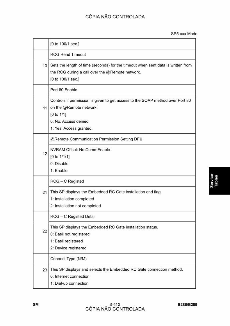
SP5-xxx Mode
SM 5-113 B286/B289
Serv
ice
Tabl
es
[0 to 100/1 sec.]
RCG Read Timeout
10 Sets the length of time (seconds) for the timeout when sent data is written from
the RCG during a call over the @Remote network.
[0 to 100/1 sec.]
Port 80 Enable
11
Controls if permission is given to get access to the SOAP method over Port 80
on the @Remote network.
[0 to 1/1]
0: No. Access denied
1: Yes. Access granted.
@Remote Communication Permission Setting DFU
12 NVRAM Offset: NrsCommEnable
[0 to 1/1/1]
0: Disable
1: Enable
RCG � C Registed
21 This SP displays the Embedded RC Gate installation end flag.
1: Installation completed
2: Installation not completed
RCG � C Registed Detail
22 This SP displays the Embedded RC Gate installation status.
0: Basil not registered
1: Basil registered
2: Device registered
Connect Type (N/M)
23 This SP displays and selects the Embedded RC Gate connection method.
0: Internet connection
1: Dial-up connection
CÓPIA NÃO CONTROLADA
CÓPIA NÃO CONTROLADA
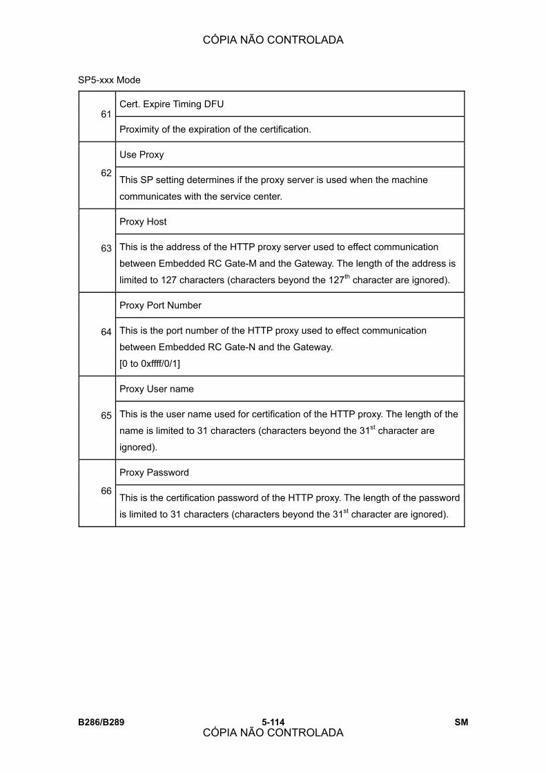
SP5-xxx Mode
B286/B289 5-114 SM
Cert. Expire Timing DFU 61
Proximity of the expiration of the certification.
Use Proxy
62 This SP setting determines if the proxy server is used when the machine
communicates with the service center.
Proxy Host
63 This is the address of the HTTP proxy server used to effect communication
between Embedded RC Gate-M and the Gateway. The length of the address is
limited to 127 characters (characters beyond the 127th character are ignored).
Proxy Port Number
64 This is the port number of the HTTP proxy used to effect communication
between Embedded RC Gate-N and the Gateway.
[0 to 0xffff/0/1]
Proxy User name
65 This is the user name used for certification of the HTTP proxy. The length of the
name is limited to 31 characters (characters beyond the 31st character are
ignored).
Proxy Password
66 This is the certification password of the HTTP proxy. The length of the password
is limited to 31 characters (characters beyond the 31st character are ignored).
CÓPIA NÃO CONTROLADA
CÓPIA NÃO CONTROLADA
SP5-xxx Mode
SM 5-115 B286/B289
Serv
ice
Tabl
es
Note: The proxy number, user name, and password comprise proprietary operator
information required by the service technician to do the necessary settings for Embedded
RC Gate-N. To prevent unauthorized access this information, these SP settings do not
appear in the SMC report.
CERT: Up State
Displays the state of the certification update used for Embedded RC Gate. If
Embedded RC Gate has not been set up, These SP settings are done
automatically as soon as Embedded RC Gate is set up.
0 The certification used by Embedded RC Gate is set correctly.
1 The certification request (SetAuthKey) for update has been received
from the GW URL and certification is presently being updated.
2 The certification update is completed and the GW URL is being
notified of the successful update.
3 The certification update failed, and the GW URL is being notified of
the failed update.
4 The period of the certification has expired and new request for an
update is being sent to the GW URL.
11 A rescue update for certification has been issued and a rescue
certification setting is in progress for the rescue GW connection.
12 The rescue certification setting is completed and the GW URL is
being notified of the certification update request.
13
The notification of the request for certification update has completed
successfully, and the system is waiting for the certification update
request from the rescue GW URL.
14 The notification of the certification request has been received from
the rescue GW URL, and the certification is being stored.
67
15 The certification has been stored, and the GW URL is being notified
of the successful completion of this event.
CÓPIA NÃO CONTROLADA
CÓPIA NÃO CONTROLADA
SP5-xxx Mode
B286/B289 5-116 SM
16 The storing of the certification has failed, and the GW URL is being
notified of the failure of this event.
17
The certification update request has been received from the GW
URL, the GW URL was notified of the results of the update after it
was completed, but a certification error has been received, and the
rescue certification is being recorded.
18 The rescue certification of No. 17 has been recorded, and the GW
URL is being notified of the failure of the certification update.
CERT: Error
Displays a number code that describes the reason for the notification
requesting the certification update.
0 Normal. No request for certification update in progress.
1 Certification update in progress due to expiration of certification.
2 SSL error has been issued after the certification has expired.
3 There has been a shift from a common to individual certification.
4 There has been a common certification without ID2.
5 No certification has been issued.
68
6 GW URL does not exist.
CERT: Up ID 69
The ID of the request for certification.
Firm Up Status 83
Displays the status of the firmware update.
Non-HDD Firm Up
84 This setting determines if the firmware can be updated, even without the HDD
installed.
CÓPIA NÃO CONTROLADA
CÓPIA NÃO CONTROLADA

SP5-xxx Mode
SM 5-117 B286/B289
Serv
ice
Tabl
es
Firm Up User Check
85 This SP setting determines if the operator can check the previous version of
the firmware before the firmware update execution. If the option to check the
previous version is selected, a notification is sent to the system manager and
the firmware update is done with the firmware files from the URL.
Firmware Size
86 Allows the service technician to check the size of the firmware data files
during the firmware update execution.
CERT: Macro Version 87
Displays the macro version of the @Remote certification
CERT: PAC Version 88
Displays the PAC version of the @Remote certification.
CERT: ID2 Code
89 Displays ID2 for the @Remote certification. Spaces are displayed as
underscores (_). Asterisks (****) indicate that no @Remote certification
exists.
CERT: Subject
90 Displays the common name of the @Remote certification subject. CN = the
following 17 bytes. Spaces are displayed as underscores (_). Asterisks (****)
indicate that no DESS exists.
CERT: Serial Number
91 Displays serial number for the @Remote certification. Asterisks (****) indicate
that no DESS exists.
CERT: Issuer
92 Displays the common name of the issuer of the @Remote certification. CN =
the following 30 bytes. Asterisks (****) indicate that no DESS exists.
CÓPIA NÃO CONTROLADA
CÓPIA NÃO CONTROLADA

SP5-xxx Mode
B286/B289 5-118 SM
CERT: Valid Start
93 Displays the start time of the period for which the current @Remote
certification is enabled.
CERT: Valid End
94 Displays the end time of the period for which the current @Remote
certification is enabled.
Server CN Check DFU
95 [0 to 1/0/1]
0: Thorough check. Set when connected to @Remote gateway.
1: Moderate check. Set when connected to @Remote emulator
GW Host DFU 96
Used by designers for debugging and evaluation of gateway security devices.
GW URL Path DFU 97
Used by designers for debugging and evaluation of gateway security devices.
Debug Rescue G/W URL Set DFU
99 Executing this SP sets �i01/AS� in the rescue gateway URL path. Used for
2-line displays, or when input with lowercase alphanumeric characters is not
possible.
CÓPIA NÃO CONTROLADA
CÓPIA NÃO CONTROLADA

SP5-xxx Mode
SM 5-119 B286/B289
Serv
ice
Tabl
es
Selection Country DFU
150
Used only for Embedded RC Gate-M to select a country name. Once the
number/country is selected, the following settings are checked:
! Access point telephone number
! Dial-up user name
! Modem parameters set for the country
[0 to 10/*/1]
*: 0: Japan, 1: USA, 3: Europe
0:Japan, 1:USA, 2:Canada, 3:UK, 4:Germany, 5:France, 6:Italy,
7:Netherlands, 8:Belgium, 9:Luxembourg, 10:Spain
Line Type Automatic Judgement DFU
151
Used only for Embedded RC Gate-M to determine whether the dial-up line is
for manual rotary or push-button tone dialing.
! The status of the execution of this SP (dialing in progress, success,
failure) is written to SP5816-152.
! If the check succeeds, the number (dial or push number) written to
SP5816-153 can be used
! If the check succeeds, the number of the carrier line written to
SP816-154 can be used.
Line Type Judgement Result DFU
152 Used only for Embedded RC Gate-M to display the status of the execution of
SP5816-151 identify the type of line.
0 Success
1 Currently dialing
2 Line abnormal
3 Could not confirm external line carrier with automatic detection.
4 Line disconnected
5 Power supply insufficient
CÓPIA NÃO CONTROLADA
CÓPIA NÃO CONTROLADA

SP5-xxx Mode
B286/B289 5-120 SM
6 Line determination not supported
7 Error due to fax transmission in progress.
8 Other error
9 Line type identification still in progress. Please wait.
Selection Dial/Push DFU
153 Used only for Embedded RC Gate-M to set the telephone number of the
dial-up access point of the line checked with SP5816-151. If a number is
entered, use that number. If a number is not displayed, use the pre-set value
for that country.
Outside Line Outgoing Number DFU
154 Used only for Embedded RC Gate-M to set the number of the PSTN number
to dial out where Embedded RC Gate-M is used with a PBX system. If a
number is set here, the number will be replaced by the number returned by
the successful execution of SP5816-151.
Dial Up User Name DFU
156 This is the user name for dialing at the access point where Embedded RC
Gate-M is used.
Note: Numbers with spaces or # marks appear enclosed with quotation
marks in the user name.
Dial Up Password DFU
157 This is the password for dialing at the access point where Embedded RC
Gate-M is used.
Note: Numbers with spaces or # marks appear enclosed with quotation
marks in the user name.
Local Phone Number DFU
161 This is the number of the local line where Embedded RC Gate-M is
connected. This is the line used to communicate with the Call Center.
162 Connection Timing Adjustment Incoming DFU
CÓPIA NÃO CONTROLADA
CÓPIA NÃO CONTROLADA

SP5-xxx Mode
SM 5-121 B286/B289
Serv
ice
Tabl
es
When the Call Center calls out to the access point where Embedded RC
Gate-M is used, the ID tone (*#1#) is sent repeatedly. This SP sets the
amount of time to elapse for ID tone output.
[0 to 24/1/1 pause count]
1 pause count = 2 sec.
Access Point DFU
163 This is the dial-up telephone line number of the access point connected to
Embedded RC Gate-M. If a number is entered here that number is used. If no
number is entered here then the pre-set country setting is used.
Line Connecting DFU
164
This SP code should be set for the customer using Embedded RC Gate-M,
depending on the line usage (whether line is shared with a fax or not).
[0 to 1/0/1]
0: Line shared with facsimile
1: Line not shared with facsimile
Modem Serial No. DFU
173 This SP code displays the serial number of the Embedded RC Gate-M
(modem).
Retransmission Limit DFU
174 Use this SP to manually send a registration update request to Embedded RC
Gate-M.
RCG-C M Debug Bit SW DFU
186
This SP code sets the bit switch for Embedded RC Gate-M to enable
debugging.
[0 to 1/0/1]
0: Enable
1: Disable
CÓPIA NÃO CONTROLADA
CÓPIA NÃO CONTROLADA
SP5-xxx Mode
B286/B289 5-122 SM
FAX TX Priority DFU
187
This SP is used with SP5816-164 for users who are using a line shared with a
facsimile unit.
[0 to 1/0/1]
0: Disabled. Embedded RC Gate-M continues to operate if a fax transmission
starts on the same line.
1: Enabled. Fax transmissions have priority. Embedded RC Gate-M will shut
down when a fax transmission begins.
Manual Polling
200 Executes manual polling. Embedded RC Gate periodically polls the
@Remote Gateway by HTTPS. This is called �center polling.� Use this SP at
any time to poll the @Remote supply center.
Regist: Status
Displays a number that indicates the status of the @Remote service device.
0 Neither the @Remote device nor Embedded RC Gate device are set.
1
The Embedded RC Gate device is being set. Only Box registration is
completed. In this status the Basil unit cannot answer a polling
request.
2 The Embedded RC Gate device is set. In this status the Basil unit
cannot answer a polling request.
3 The @Remote device is being set. In this status the Embedded RC
Gate device cannot be set.
201
4 The @Remote module has not started.
Letter Number
202 Allows entry of the number of the request needed for the Embedded RC Gate
device.
CÓPIA NÃO CONTROLADA
CÓPIA NÃO CONTROLADA

SP5-xxx Mode
SM 5-123 B286/B289
Serv
ice
Tabl
es
Confirm Execute 203
Executes the inquiry request to the @Remote GW URL.
Confirm Result
Displays a number that indicates the result of the inquiry executed with
SP5816 203.
0 Succeeded
1 Inquiry number error
2 Registration in progress
3 Proxy error (proxy enabled)
4 Proxy error (proxy disabled)
5 Proxy error (Illegal user name or password)
6 Communication error
7 Certification update error
8 Other error
204
9 Inquiry executing
Confirm Place
205 Displays the result of the notification sent to the device from the GW URL in
answer to the inquiry request. Displayed only when the result is registered at
the GW URL.
Register Execute 206
Executes Embedded RC Gate Registration.
CÓPIA NÃO CONTROLADA
CÓPIA NÃO CONTROLADA

SP5-xxx Mode
B286/B289 5-124 SM
Register Result
Displays a number that indicates the registration result.
0 Succeeded
2 Registration in progress
3 Proxy error (proxy enabled)
4 Proxy error (proxy disabled)
5 Proxy error (Illegal user name or password)
6 Communication error
7 Certification update error
8 Other error
207
9 Registration executing
Error Code
Displays a number that describes the error code that was issued when either
SP5816 204 or SP5816 207 was executed.
Cause Code Meaning
-11001 Chat parameter error
-11002 Chat execution error Illegal Modem Parameter
-11003 Unexpected error
-12002 Inquiry, registration attempted without
acquiring device status.
-12003
Attempted registration without
execution of an inquiry and no previous
registration.
208
Operation Error, Incorrect
Setting
-12004 Attempted setting with illegal entries for
CÓPIA NÃO CONTROLADA
CÓPIA NÃO CONTROLADA

SP5-xxx Mode
SM 5-125 B286/B289
Serv
ice
Tabl
es
certification and ID2.
-2385
Attempted dial up overseas without the
correct international prefix for the
telephone number.
-2387 Not supported at the Service Center
-2389 Database out of service
-2390 Program out of service
-2391 Two registrations for same device
-2392 Parameter error
-2393 Basil not managed
-2394 Device not managed
-2395 Box ID for Basil is illegal
-2396 Device ID for Basil is illegal
-2397 Incorrect ID2 format
Error Caused by
Response from GW URL
-2398 Incorrect request number format
209 Instl Clear
Releases a machine from its embedded RCG setup.
250 CommLog Print
Prints the communication log.
CÓPIA NÃO CONTROLADA
CÓPIA NÃO CONTROLADA

SP5-xxx Mode
B286/B289 5-126 SM
5821 Remote Service Address (Japan Only)
1 CSS PI Device Code
Sets the PI device code. After changing this
setting, you must switch the machine off and
on.
2 RCG IP Address
Sets the IP address of the RCG (Remote
Communication Gate) destination for call
processing at the remote service center.
[00000000h to FFFFFFFFh/ 00000000h /
NVRAM Data Upload
5824 Uploads the UP and SP mode data (except for counters and the serial
number) from NVRAM on the control board to a flash memory card.
While using this SP mode, always keep the front cover open. This prevents
a software module accessing the NVRAM during the upload.
NVRAM Data Download
5825 Downloads the content of a flash memory card to the NVRAM on the control
board.
5828 Network Setting
65 Job Spool Setting
Switches job spooling spooling on and off.
0: No spooling 1: Spooling enabled
66 Job Spool Clear
This SP determines whether the job interrupted at power off is resumed at the
next power on. This SP operates only when SP5828065 is set to 1.
1: Resumes printing spooled jog.
0: Clears spooled job.
CÓPIA NÃO CONTROLADA
CÓPIA NÃO CONTROLADA

SP5-xxx Mode
SM 5-127 B286/B289
Serv
ice
Tabl
es
69 Job Spool Pro to col
This SP 8etermines whether job spooling is enabled or disabled for each pro to
col. This is a 8-bit setting.
0 LPR 4
BMLinks
(Japan
Only)
1
FTP
(Not
Used)
5 DIPRINT
2 IPP 6
Reserved
(Not
Used)
3 SMB 7
Reserved
(Not
Used)
84 Setting List Print Settings List
Prints a list of the NCS parameter settings.
90 TELNET Operation Settings: TELNET (0:OFF 1:ON)
Disables or enables Telnet operation. If this SP is disabled, the Telnet port is
closed.
[0 to 1/1]
0: Disable
1: Enable
91 Web Operation Web (0:OFF 1:ON)
Disables or enables the Web operation.
[0 to 1/1]
0: Disable
1: Enable
CÓPIA NÃO CONTROLADA
CÓPIA NÃO CONTROLADA

SP5-xxx Mode
B286/B289 5-128 SM
145 Active IPv6 Link Local Address
This is the IPv6 local address referenced on the Ethernet or wireless LAN
(802.11b) in the format:
�Link-Local address� + �Prefix Length�
The IPv6 address consists of a total 128 bits configured in 8 blocks of 16 bits
each. These notations can be abbreviated. See �Note: IPV6 Addresses � below
this table.
147 Active IPv6 Stateless Address 1
149 Active IPv6 Stateless Address 2
151 Active IPv6 Stateless Address 3
153 Active IPv6 Stateless Address 4
155 Active IPv6 Stateless Address 5
SP codes 147 to 155 are the IPv6 stateless addresses (1 to 5) referenced on
the Ethernet or wireless LAN (802.11b) in the format:
�Stateless Address� + �Prefix Length�
The IPv6 address consists of a total 128 bits configured in 8 blocks of 16 bits
each.
156 IPv6 Manual Address
This SP is the IPv6 manually set address referenced on the Ethernet or
wireless LAN (802.11b) in the format:
�Manual Set Address� + �Prefix Length�
The IPv6 address consists of a total 128 bits configured in 8 blocks of 16 bits
each. These notations can be abbreviated. See �Note: IPV6 Addresses� below
this table.
CÓPIA NÃO CONTROLADA
CÓPIA NÃO CONTROLADA
SP5-xxx Mode
SM 5-129 B286/B289
Serv
ice
Tabl
es
158 IPv6 Gateway Address
This SP is the IPv6 gateway address referenced on the Ethernet or wireless
LAN (802.11b). The IPv6 address consists of a total 128 bits configured in 8
blocks of 16 bits each. These notations can be abbreviated. See �Note: IPV6
Addresses � below this table.
Note: IPV6 Addresses
Ethernet and the Wireless LAN (802.11b) reference the IPV6 �Link-Local address + Prefix
Length.� The IPV6 address consists of 128 bits divided into 8 blocks of 16 bits:
aaaa:bbbb:cccc:dddd:eeee:ffff:gggg:hhhh:
The prefix length is inserted at the 17th byte (Prefix Range: 0x0~0x80). The initial setting is
0x40(64).
For example, the data:
2001123456789012abcdef012345678940h
is expressed:
2001:1234:5678:9012:abcd:ef01:2345:6789: prefixlen 64
However, the actual IPV6 address display is abbreviated according to the following rules.
Rules for Abbreviating IPV6 Addresses
1. The IPV6 address is expressed in hexadecimal delmited by colons (:) with the
following characters:
0123456789abcdefABCDEF
2. A colon is inserted as a delimiter every 4th hexadecimal character.
fe80:0000:0000:0000:0207:40ff:0000:340e
3. The notations can be abbreviated by elminating zeros where the MSB and digits
following the MSB are zero. The example in �2� above, then, becomes:
fe80:0:0:0207:40ff:0:340e
4. Sections where only zeros exist can be abbreviated with double colons (::). This
abbreviation can be done also where succeeding sections contain only zeros (but this
can be done only at one point in the address). The example in �2� and �3� above then
becomes: fe80::207:40ff:0:340e (only the first null sets zero digits are abbreviated as
�::�)
� or-
fe80:0:0:0:207:40ff::340e (only the last null set before �340e� is abbreviated as �::�)
CÓPIA NÃO CONTROLADA
CÓPIA NÃO CONTROLADA

SP5-xxx Mode
B286/B289 5-130 SM
Initial Setting Clear
5831 This SP clears all the User Tools settings are restores them to their factory
default settings.
HDD Formatting
5832 Enter the SP number for the partition to initialize, then press #. When the
execution ends, turn the machine power off and on.
1 HDD Formatting (All)
2 HDD Formatting (IMH)
3 HDD Formatting (Thumbnail)
4 HDD Formatting (Job Log)
5 HDD Formatting (Printer Fonts)
6 HDD Formatting (User Info)
7 Mail RX Data
8 Mail TX Data
9 HDD Formatting (Data for Design)
10 HDD Formatting (Log)
11 HDD Formatting (Ridoc I/F) (for Ridoc DesktopBinder)
CÓPIA NÃO CONTROLADA
CÓPIA NÃO CONTROLADA
SP5-xxx Mode
SM 5-131 B286/B289
Serv
ice
Tabl
es
5836 Capture Settings
1 Capture Function
With this function disabled, the settings related to the
capture feature cannot be initialized, displayed, or
selected. DFU
[0 to 1/0/1]
0: Disable
1: Enable
2 Panel Setting
Determines whether each capture related setting can
be selected or updated from the initial system screen.
[0 to 1/0/1]
0: Disable
1: Enable
The setting for SP5836-1 has priority.
3 Print Back-up Function
Determines whether the print back-up function setting
can be changed.
[0 to 1/0/1]
0: Disable
1: Enable
71
Capture Setting:
Resolution Conversion
for Color
Determines the resolution conversion ratio when a
Color image document is sent to the Document Server
via the MLB (Media Link Board).
[0 to 2/0/1]
0: 1 x
1: ½ x
2: ¼ x
72
Capture Setting:
Resolution Conversion
for Copy Text
Determines the resolution conversion ratio when a
Copy Text image document is sent to the Document
Server via the MLB (Media Link Board).
[0 to 2/0/1]
0: 1 x
1: ½ x
2: ¼ x
CÓPIA NÃO CONTROLADA
CÓPIA NÃO CONTROLADA

SP5-xxx Mode
B286/B289 5-132 SM
73
Capture Setting:
Resolution Conversion
for Copy (Others)
Determines the resolution conversion ratio when a
Copy image document other than Text mode is sent to
the Document Server via the MLB (Media Link Board).
[0 to 2/0/1]
0: 1 x
1: ½ x
2: ¼ x
74 Reduction for Printer
Color
[0~3/1]
0:1 1:1/2 2:1/3 3:1/4 DFU
75
Capture Setting:
Resolution Conversion
for Binary Print
Determines the resolution conversion ratio when a
binary print image document is sent to the Document
Server via the MLB (Media Link Board).
[0 to 2/0/1]
0: 1 x
1: ½ x
2: ¼ x
76
Capture Setting:
Resolution Conversion
for Dither Print (1200
dpi)
Determines the resolution conversion ratio when the
Dither print image document is sent to the Document
Server via the MLB (Media Link Board).
[1 to 3/1/1]
1: ½ x
2: ¼ x
3: 1/8 x
81 Format for Copy Color
[0 to 3/1]
0: JFIF/JPEG, 1: TIFF/MMR, 2: TIFF/MH, 3: TIFF/MR
DFU
CÓPIA NÃO CONTROLADA
CÓPIA NÃO CONTROLADA

SP5-xxx Mode
SM 5-133 B286/B289
Serv
ice
Tabl
es
82 Capture Setting: Format
for Copy Text
Determines the image format for Copy Text images
sent to the Document Server via the MLB (Media Link
Board).
[0 to 3/1/1]
0: JFIF/JPEG
1: TIFF/MMR
2: TIFF/MH
3: TIFF/MR
83 Capture Setting: Format
for Copy (Others)
Determines the image format for Copy (other than
text) images sent to the Document Server via the MLB
(Media Link Board).
[0 to 3/1/1]
0: JFIF/JPEG
1: TIFF/MMR
2: TIFF/MH
3: TIFF/MR
85 Capture Setting: Format
for Binary Print
Determines the image format for Binary Print images
sent to the Document Server via the MLB (Media Link
Board).
[0 to 3/1/1]
0: JFIF/JPEG
1: TIFF/MMR
2: TIFF/MH
3: TIFF/MR
86
Capture Setting: Format
for Dither Print
(1200dpi)
Determines the image format for Dither Print images
sent to the Document Server via the MLB (Media Link
Board).
[0 to 3/1/1]
0: JFIF/JPEG
1: TIFF/MMR
2: TIFF/MH
3: TIFF/MR
CÓPIA NÃO CONTROLADA
CÓPIA NÃO CONTROLADA
SP5-xxx Mode
B286/B289 5-134 SM
91 Capture Setting: Page
Quality for JPEG
Determines the quality level of JPEG images sent to
the Document Server via the MLB (Media Link Board).
[5 to 95/50/1]
92
Capture Setting: Page
Quality for JPEG (High
Quality)
Determines the quality level of JPEG images for high
quality sent to the Document Server via the MLB
(Media Link Board).
[5 to 95/60/1]
93
Capture Setting: Page
Quality for JPEG (Low
Quality)
Determines the quality level of JPEG images for low
quality sent to the Document Server via the MLB
(Media Link Board).
[5 to 95/40/1]
94 Capture Setting: Format
for Backup File
Determines the format of the backup files.
[0 to 2/0/1]
0: TIFF
1: JPEG
2: For printing
This function can be selected only if SP5836-3 is set
to �1.�
95
Capture Setting:
Resolution Conversion
for Backup File
Determines the resolution conversion ratio for the
backup files.
[0 to 3/2/1]
0: 1x
1: ½x
2: 1/3 x
3: ¼x
96 Default User Name for
Backup Files
Allows the user to set the default user name for the
backup files created during the copy job. 20
characters are allowed.
CÓPIA NÃO CONTROLADA
CÓPIA NÃO CONTROLADA

SP5-xxx Mode
SM 5-135 B286/B289
Serv
ice
Tabl
es
97 Capture Setting: Page
Quality for JPEG
Determines the quality level of JPEG images for
backup files.
[0 to 2/0/1]
0: Standard quality
1: Low quality
2: High quality
This function can be selected only if SP5836-95 is set
to �2.�
98
Capture Setting:
Gamma SW for Backup
File
Removes the ghost images transferred from the back
sides of double-sided originals.
1: Enable
0: Disable
5840 IEEE 802.11b
Channel MAX
6 Sets the maximum range of the bandwidth for the wireless LAN. This bandwidth
setting varies for different countries.
[1 to 14/1]
Channel MIN
7 Sets the minimum range of the bandwidth for operation of the wireless LAN. This
bandwidth setting varies for different countries.
[1 to 14/1]
CÓPIA NÃO CONTROLADA
CÓPIA NÃO CONTROLADA

SP5-xxx Mode
B286/B289 5-136 SM
WEP Key Select
11
Determines how the initiator (SBP-2) handles subsequent login requests.
[00 to 11/00/1]
Note: There are four settings (binary numbers): 00, 01, 10, 11. These settings
are possible only after the wireless LAN card has been installed.
00: 1st key. If the initiator receives another login request while logging in, the
request is refused.
01, 10, 11: 2nd, 3rd, 4th keys are �Reserved.�
Supply Name Setting
5841 Use the soft keyboard of this SP to enter the names and numbers of
consumables. These are the names that appear on the display when [Inquiry] is
pressed on the User Tools screen.
5842 GWWS Analysis Mode DFU
Setting 1
Bit Groups
0 System & other groups (LSB)
1 Capture related
2 Certification related
3 Address book related
4 Machine management related
5 Output related (printing, delivery)
1 This is a debugging tool. It sets
the debugging output mode of
each Net File process.
Bit SW 0011 1111
6 Repository related
CÓPIA NÃO CONTROLADA
CÓPIA NÃO CONTROLADA

SP5-xxx Mode
SM 5-137 B286/B289
Serv
ice
Tabl
es
Setting 2 Bit
0-6 Not Used
2
This SP codes sets the optional
setting for message log time
stamp. Bit 7 is the 5682
message log where the
following are set:
7
Message log
1: mm:ss:ms
0: mm:ss (time)
5844 USB
1 Transfer Rate
Sets the speed for USB data transmission.
[Full Speed], [Auto Change]
2 Vendor ID
Sets the vendor ID:
Initial Setting: 0x05A Ricoh Company
[0x0000~0xFFFF/1] DFU
3 Product ID
Sets the product ID.
[0x0000~0xFFFF/1] DFU
4 Device Release No.
Sets the device release number of the BCD (binary coded decimal) display.
[0000~9999/1] DFU
Enter as a decimal number. NCS converts the number to hexadecimal number
recognized as the BCD.
CÓPIA NÃO CONTROLADA
CÓPIA NÃO CONTROLADA

SP5-xxx Mode
B286/B289 5-138 SM
Delivery Server Setting 5845
Provides items for delivery server settings.
FTP Port No. [0 to 65535 / 3670 / 1]
1 Sets the FTP port number used when image files are sent to the Scan Router
Server.
IP Address (Primary) Range: 000.000.000.000 to 255.255.255.255
2 Use this SP to set the Scan Router Server address. The IP address under the
transfer tab can be referenced by the initial system setting.
Delivery Error Display Time Netfiles: [0 to 999 / 300 / 1]
6 Use this setting to determine the length of time the prompt message is displayed
when a test error occurs during document transfer with the NetFile application
and an external device.
8 IP Address (Secondary) Range: 000.000.000.000 to
255.255.255.255
Specifies the IP address assigned to the computer designated to function as the
secondary delivery server of Scan Router. This SP allows only the setting of the
IP address without reference to the DNS setting.
9 Delivery Server Model [0 to 4/ 0 / 1]
Allows changing the model of the delivery server registered by the I/O device.
0: Unknown
1: SG1 Provided
2: SG1 Package
3: SG2 Provided
4: SG2 Package
CÓPIA NÃO CONTROLADA
CÓPIA NÃO CONTROLADA
SP5-xxx Mode
SM 5-139 B286/B289
Serv
ice
Tabl
es
Delivery Svr Capability
Changes the capability of the registered that the I/O device registered.
[0 to 255 / 0 / 1]
(7) [0000 0000] (1)
Bit7 = 1 Comment information exists
Bit6 = 1 Direct specification of mail address possible
Bit5 = 1 Mail RX confirmation setting possible
Bit4 = 1 Address book automatic update function exists
Bit3 = 1 Fax RX delivery function exists
Bit2 = 1 Sender password function exists
Bit1 = 1 Function to link MK-1 user and Sender exists
10
Bit0 = 1 Sender specification required (if set to 1, Bit6 is set to �0�)
Delivery Svr.Capability (Ext)
11 These settings are for future use. They will let you increase the number of
registered devices (in addition to those registered for SP5845-10).
There are eight bits (Bit 0 to Bit 7). All are unused at this time.
13 Server Scheme (Primary)
14 Server Port Number (Primary)
15 Server URL Path (Primary)
16 Server Scheme (Secondary)
17 Server Port Number (Secondary)
18 Server URL Path (Secondary)
19 Capture Server Scheme
20 Capture Server Port Number
CÓPIA NÃO CONTROLADA
CÓPIA NÃO CONTROLADA

SP5-xxx Mode
B286/B289 5-140 SM
21 Capture Server URL Path
SP codes 13 to 21 specify the schemes, port numbers, and URL paths of the
primary, secondary, and capture servers.
22 Instant Trans Off
Switches instant transmission off/on.
[0 to 1/1/1]
0: Off. Instant transmission not possible with network setting errors.
1: On. Instant transmission possible with network setting errors.
Note:
! The machine will continue to transmit over the network, even if the network
settings are incorrect. (This causes multiple errors, of course.)
! With this SP off, the machine will stop communicating with the network if the
settings are wrong. This reduces the amount of spurious network traffic
caused by errors due to incorrect settings.
5846 UCS Setting
Machine ID (for Delivery Server)
1
Displays the unique device ID in use by the delivery server directory. The value
is only displayed and cannot be changed.
This ID is created from the NIC MAC or IEEE 1394 EUI.
The ID is displayed as either 6-byle or 8-byte binary.
6-byte
%02X.%02X.%02X.%02X.%02X.%02X
8-byte
%02X.%02X.%02X.%02X.%02X.%02X.%02X.%02X
Machine ID Clear (Delivery Server)
2 Clears the unique ID of the device used as the name in the file transfer directory.
Execute this SP if the connection of the device to the delivery server is unstable.
After clearing the ID, the ID will be established again automatically by cycling the
machine off and on.
CÓPIA NÃO CONTROLADA
CÓPIA NÃO CONTROLADA

SP5-xxx Mode
SM 5-141 B286/B289
Serv
ice
Tabl
es
Maximum Entries
3 Changes the maximum number of entries that UCS can handle.
[2000 to 50000/1]
If a value smaller than the present value is set, the UCS managed data is
cleared, and the data (excluding user code information) is displayed.
Delivery Server Retry Timer
6 Sets the interval for retry attempts when the delivery server fails to acquire the
delivery server address book.
[0 to 255/1 s]
0: No retries
Delivery Server Retry Times
7 Sets the number of retry attempts when the delivery server fails to acquire the
delivery server address book.
[0 to 255/1]
Delivery Server Maximum Entries
8 Lets you set the maximum number of account entries and information about the
users of the delivery server controlled by UCS.
[20000 to 50000/1]
LDAP Search Timeout
10 Sets the length of the time-out for the search of the LDAP server.
[1 to 255/1]
CÓPIA NÃO CONTROLADA
CÓPIA NÃO CONTROLADA

SP5-xxx Mode
B286/B289 5-142 SM
Addr Book Migration (SD -> HDD)
40
This SP moves the address book data from an SD card to the HDD. You must
turn the machine power off and on after executing this SP.
1. Turn the machine off.
2. Install the HDD.
3. Insert the SD card with the address book data in SD card Slot C3.
4. Turn the machine on.
5. Do SP5846-40.
6. Turn the machine off.
7. Remove the SD card from SD card Slot C3.
8. Turn the machine on.
Notes:
! Executing this SP overwrites any address book data already on the HDD
with the data from the SD card.
! We recommend that you back up all directory information to an SD card with
SP5846-51 before you execute this SP.
! After the address book data is copied to HDD, all the address book data is
deleted from the source SD card. If the operation fails, the data is not erased
from the SD card.
Fill Addr Acl Info.
41
This SP must be executed immediately after installation of an HDD unit in a
basic machine that previously had no HDD. The first time the machine is
powered on with the new HDD installed, the system automatically takes the
address book from the NVRAM and writes it to the new HDD. However, the new
address book on the HDD can be accessed only by the system administrator at
this stage. Executing this SP by the service technician immediately after power
on grants full address book access to all users.
Procedure
1. Turn the machine off.
2. Install the new HDD.
3. Turn the machine on.
4. The address book and its initial data are created on the HDD automatically.
However, at this point the address book can be accessed by only the
CÓPIA NÃO CONTROLADA
CÓPIA NÃO CONTROLADA
SP5-xxx Mode
SM 5-143 B286/B289
Serv
ice
Tabl
es
system administrator or key operator.
5. Enter the SP mode and do SP5846-41. After this SP executes successfully,
any user can access the address book.
Initialize Local Address Book
47 Clears all of the address information from the local address book of a machine
managed with UCS.
Initialize Delivery Addr Book
48 Push [Execute] to delete all items (this does not include user codes) in the
delivery address book that is controlled by UCS.
Initialize LDAP Addr Book
49 Push [Execute] to delete all items (this does not include user codes) in the LDAP
address book that is controlled by UCS.
Initialize All Addr Book
50 Clears everything (including user codes) in the directory information managed
by UCS. However, the accounts and passwords of the system administrators are
not deleted.
Backup All Addr Book 51
Uploads all directory information to the SD card.
Restore All Addr Book 52
Downloads all directory information from the SD card.
Clear Backup Info.
53
Deletes the address book uploaded from the SD card in the slot. Deletes only
the files uploaded for that machine. This feature does not work if the card is
write-protected.
Note: After you do this SP, go out of the SP mode, turn the power off. Do not
remove the SD card until the Power LED stops flashing.
CÓPIA NÃO CONTROLADA
CÓPIA NÃO CONTROLADA
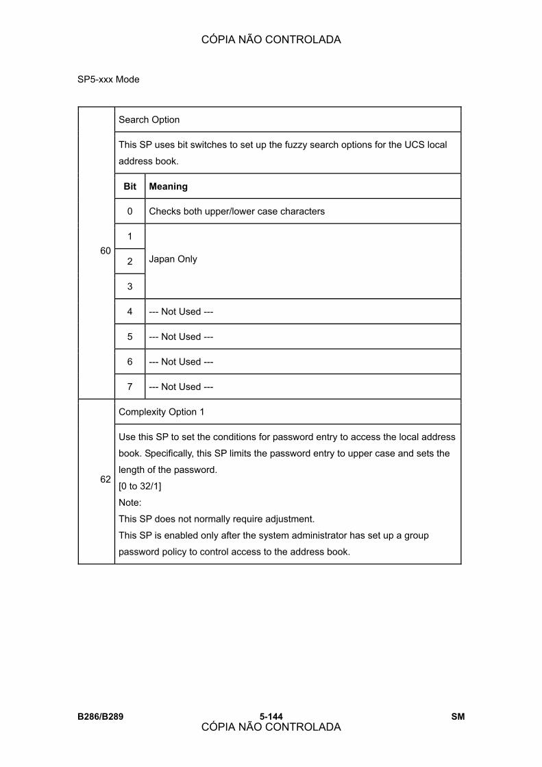
SP5-xxx Mode
B286/B289 5-144 SM
Search Option
This SP uses bit switches to set up the fuzzy search options for the UCS local
address book.
Bit Meaning
0 Checks both upper/lower case characters
1
2
3
Japan Only
4 --- Not Used ---
5 --- Not Used ---
6 --- Not Used ---
60
7 --- Not Used ---
Complexity Option 1
62
Use this SP to set the conditions for password entry to access the local address
book. Specifically, this SP limits the password entry to upper case and sets the
length of the password.
[0 to 32/1]
Note:
This SP does not normally require adjustment.
This SP is enabled only after the system administrator has set up a group
password policy to control access to the address book.
CÓPIA NÃO CONTROLADA
CÓPIA NÃO CONTROLADA
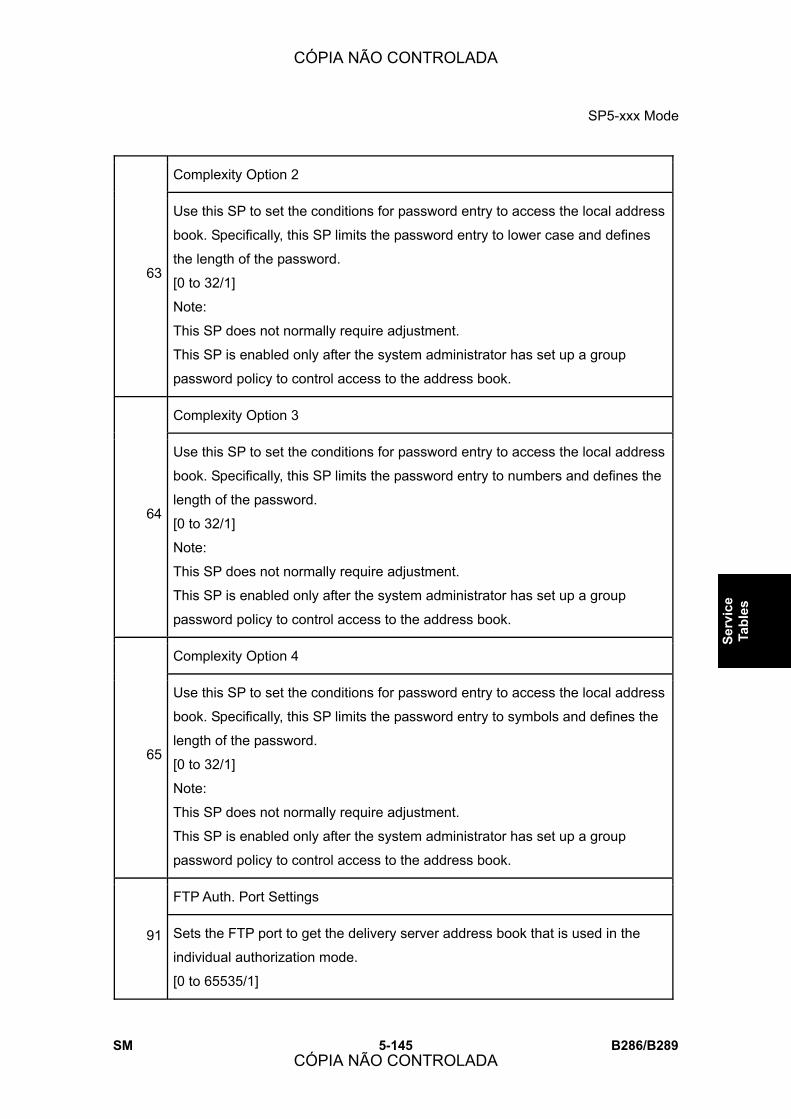
SP5-xxx Mode
SM 5-145 B286/B289
Serv
ice
Tabl
es
Complexity Option 2
63
Use this SP to set the conditions for password entry to access the local address
book. Specifically, this SP limits the password entry to lower case and defines
the length of the password.
[0 to 32/1]
Note:
This SP does not normally require adjustment.
This SP is enabled only after the system administrator has set up a group
password policy to control access to the address book.
Complexity Option 3
64
Use this SP to set the conditions for password entry to access the local address
book. Specifically, this SP limits the password entry to numbers and defines the
length of the password.
[0 to 32/1]
Note:
This SP does not normally require adjustment.
This SP is enabled only after the system administrator has set up a group
password policy to control access to the address book.
Complexity Option 4
65
Use this SP to set the conditions for password entry to access the local address
book. Specifically, this SP limits the password entry to symbols and defines the
length of the password.
[0 to 32/1]
Note:
This SP does not normally require adjustment.
This SP is enabled only after the system administrator has set up a group
password policy to control access to the address book.
FTP Auth. Port Settings
91 Sets the FTP port to get the delivery server address book that is used in the
individual authorization mode.
[0 to 65535/1]
CÓPIA NÃO CONTROLADA
CÓPIA NÃO CONTROLADA
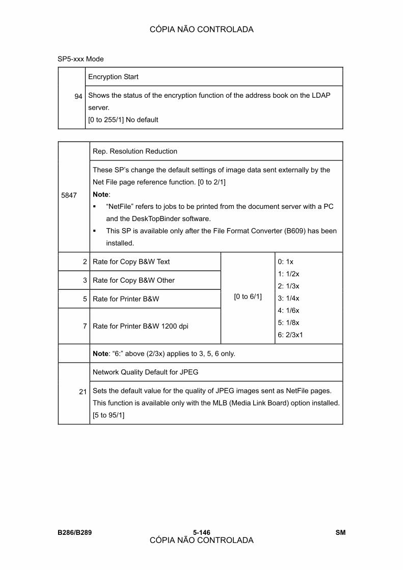
SP5-xxx Mode
B286/B289 5-146 SM
Encryption Start
94 Shows the status of the encryption function of the address book on the LDAP
server.
[0 to 255/1] No default
Rep. Resolution Reduction
5847
These SP�s change the default settings of image data sent externally by the
Net File page reference function. [0 to 2/1]
Note:
! �NetFile� refers to jobs to be printed from the document server with a PC
and the DeskTopBinder software.
! This SP is available only after the File Format Converter (B609) has been
installed.
2 Rate for Copy B&W Text
3 Rate for Copy B&W Other
5 Rate for Printer B&W
7 Rate for Printer B&W 1200 dpi
[0 to 6/1]
0: 1x
1: 1/2x
2: 1/3x
3: 1/4x
4: 1/6x
5: 1/8x
6: 2/3x1
Note: �6:� above (2/3x) applies to 3, 5, 6 only.
Network Quality Default for JPEG
21 Sets the default value for the quality of JPEG images sent as NetFile pages.
This function is available only with the MLB (Media Link Board) option installed.
[5 to 95/1]
CÓPIA NÃO CONTROLADA
CÓPIA NÃO CONTROLADA
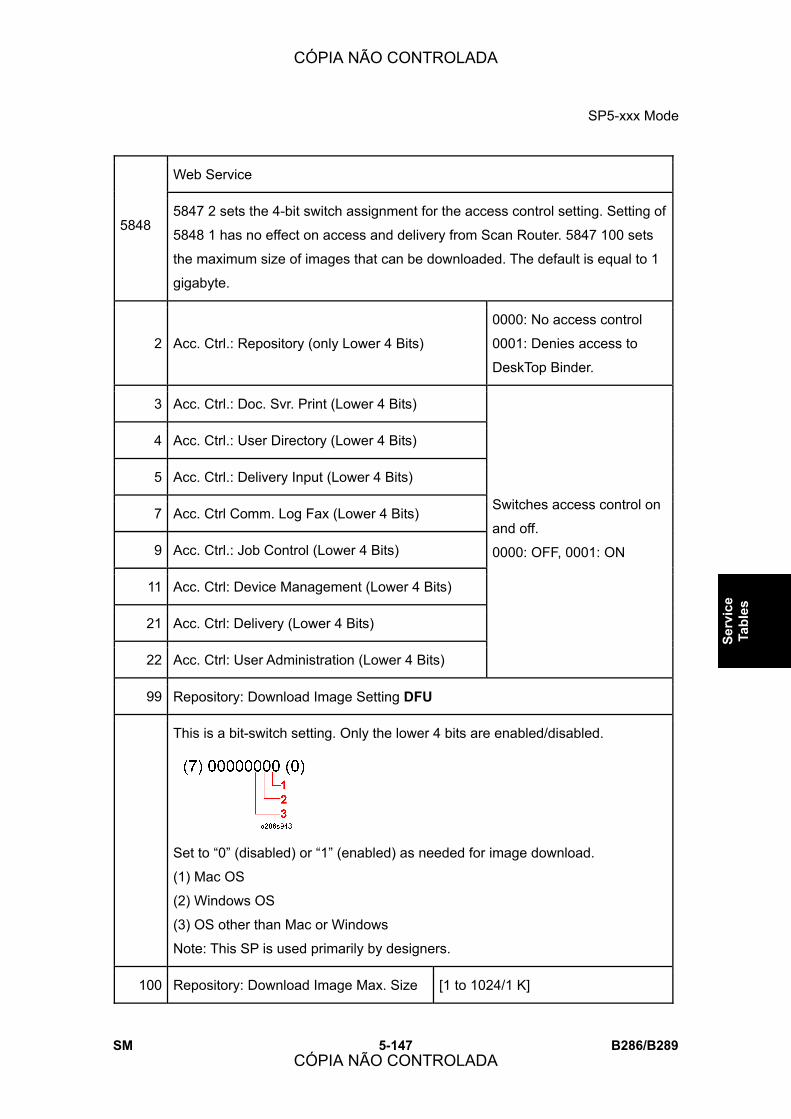
SP5-xxx Mode
SM 5-147 B286/B289
Serv
ice
Tabl
es
Web Service
5848 5847 2 sets the 4-bit switch assignment for the access control setting. Setting of
5848 1 has no effect on access and delivery from Scan Router. 5847 100 sets
the maximum size of images that can be downloaded. The default is equal to 1
gigabyte.
2 Acc. Ctrl.: Repository (only Lower 4 Bits)
0000: No access control
0001: Denies access to
DeskTop Binder.
3 Acc. Ctrl.: Doc. Svr. Print (Lower 4 Bits)
4 Acc. Ctrl.: User Directory (Lower 4 Bits)
5 Acc. Ctrl.: Delivery Input (Lower 4 Bits)
7 Acc. Ctrl Comm. Log Fax (Lower 4 Bits)
9 Acc. Ctrl.: Job Control (Lower 4 Bits)
11 Acc. Ctrl: Device Management (Lower 4 Bits)
21 Acc. Ctrl: Delivery (Lower 4 Bits)
22 Acc. Ctrl: User Administration (Lower 4 Bits)
Switches access control on
and off.
0000: OFF, 0001: ON
99 Repository: Download Image Setting DFU
This is a bit-switch setting. Only the lower 4 bits are enabled/disabled.
Set to �0� (disabled) or �1� (enabled) as needed for image download.
(1) Mac OS
(2) Windows OS
(3) OS other than Mac or Windows
Note: This SP is used primarily by designers.
100 Repository: Download Image Max. Size [1 to 1024/1 K]
CÓPIA NÃO CONTROLADA
CÓPIA NÃO CONTROLADA
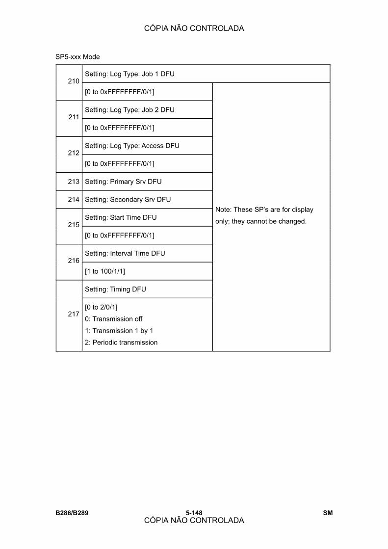
SP5-xxx Mode
B286/B289 5-148 SM
Setting: Log Type: Job 1 DFU 210
[0 to 0xFFFFFFFF/0/1]
Setting: Log Type: Job 2 DFU 211
[0 to 0xFFFFFFFF/0/1]
Setting: Log Type: Access DFU 212
[0 to 0xFFFFFFFF/0/1]
213 Setting: Primary Srv DFU
214 Setting: Secondary Srv DFU
Setting: Start Time DFU 215
[0 to 0xFFFFFFFF/0/1]
Setting: Interval Time DFU 216
[1 to 100/1/1]
Setting: Timing DFU
217 [0 to 2/0/1]
0: Transmission off
1: Transmission 1 by 1
2: Periodic transmission
Note: These SP�s are for display
only; they cannot be changed.
CÓPIA NÃO CONTROLADA
CÓPIA NÃO CONTROLADA
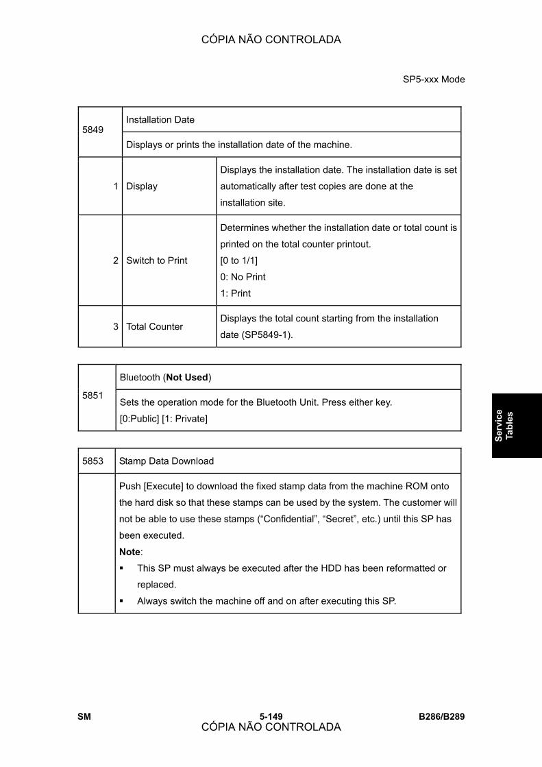
SP5-xxx Mode
SM 5-149 B286/B289
Serv
ice
Tabl
es
Installation Date 5849
Displays or prints the installation date of the machine.
1 Display
Displays the installation date. The installation date is set
automatically after test copies are done at the
installation site.
2 Switch to Print
Determines whether the installation date or total count is
printed on the total counter printout.
[0 to 1/1]
0: No Print
1: Print
3 Total Counter Displays the total count starting from the installation
date (SP5849-1).
Bluetooth (Not Used)
5851 Sets the operation mode for the Bluetooth Unit. Press either key.
[0:Public] [1: Private]
5853 Stamp Data Download
Push [Execute] to download the fixed stamp data from the machine ROM onto
the hard disk so that these stamps can be used by the system. The customer will
not be able to use these stamps (�Confidential�, �Secret�, etc.) until this SP has
been executed.
Note:
! This SP must always be executed after the HDD has been reformatted or
replaced.
! Always switch the machine off and on after executing this SP.
CÓPIA NÃO CONTROLADA
CÓPIA NÃO CONTROLADA

SP5-xxx Mode
B286/B289 5-150 SM
5856 Remote ROM Update
When set to �1� allows reception of firmware data via the local port (IEEE
1284) during a remote ROM update. This setting is reset to zero after the
machine is cycled off and on.
[0 to 1 / 0 / 1]
0: Not allowed
1: Allowed
5857 Save Debug Log
On/Off (1:ON 0:OFF)
1
Switches on the debug log feature. The debug log cannot be captured until
this feature is switched on.
[0 to 1/1]
0: OFF
1: ON
Target (2: HDD 3: SD Card)
2
Selects the destination where the debugging information generated by the
event selected by SP5858 will be stored if an error is generated
[2 to 3 /1]
2: HDD
3: SD Card
Save to HDD 5
Specifies the decimal key number of the log to be written to the hard disk.
Save to SD Card 6
Specifies the decimal key number of the log to be written to the SD Card.
CÓPIA NÃO CONTROLADA
CÓPIA NÃO CONTROLADA
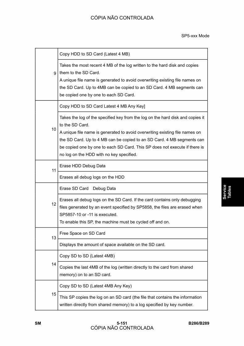
SP5-xxx Mode
SM 5-151 B286/B289
Serv
ice
Tabl
es
Copy HDD to SD Card (Latest 4 MB)
9
Takes the most recent 4 MB of the log written to the hard disk and copies
them to the SD Card.
A unique file name is generated to avoid overwriting existing file names on
the SD Card. Up to 4MB can be copied to an SD Card. 4 MB segments can
be copied one by one to each SD Card.
Copy HDD to SD Card Latest 4 MB Any Key]
10
Takes the log of the specified key from the log on the hard disk and copies it
to the SD Card.
A unique file name is generated to avoid overwriting existing file names on
the SD Card. Up to 4 MB can be copied to an SD Card. 4 MB segments can
be copied one by one to each SD Card. This SP does not execute if there is
no log on the HDD with no key specified.
Erase HDD Debug Data 11
Erases all debug logs on the HDD
Erase SD Card Debug Data
12 Erases all debug logs on the SD Card. If the card contains only debugging
files generated by an event specified by SP5858, the files are erased when
SP5857-10 or -11 is executed.
To enable this SP, the machine must be cycled off and on.
Free Space on SD Card 13
Displays the amount of space available on the SD card.
Copy SD to SD (Latest 4MB)
14 Copies the last 4MB of the log (written directly to the card from shared
memory) on to an SD card.
Copy SD to SD (Latest 4MB Any Key)
15 This SP copies the log on an SD card (the file that contains the information
written directly from shared memory) to a log specified by key number.
CÓPIA NÃO CONTROLADA
CÓPIA NÃO CONTROLADA

SP5-xxx Mode
B286/B289 5-152 SM
Make HDD Debug 16
This SP creates a 32 MB file to store a log on the HDD.
Make SD Debug 17
This SP creates a 4 MB file to store a log on an SD card.
Debug Save When
5858 These SP�s select the content of the debugging information to be saved to the
destination selected by SP5857-2. SP58583 stores one SC error specified by
number. (See �4. Troubleshooting� for descriptions of all SC codes.)
1 Engine SC Error (0:OFF 1:ON) Stores SC codes generated by main
machine engine errors.
2 Controller SC Error (0:OFF 1:ON Stores SC codes generated by GW
controller errors.
3 Any SC Error (0:OFF 1:ON [0 to 65535 / 0 / 1]
4 Jam (0:OFF 1:ON Stores jam errors.
5859 Debug Log Save Function
1 Key 1
2 Key 2
3 Key 3
4 Key 4
5 Key 5
6 Key 6
7 Key 7
8 Key 8
9 Key 9
10 Key 10
These SP�s allow you to set up to 10 keys for log
files for functions that use common memory on the
controller board.
[-9999999 to 9999999 / 0 / 1]
CÓPIA NÃO CONTROLADA
CÓPIA NÃO CONTROLADA

SP5-xxx Mode
SM 5-153 B286/B289
Serv
ice
Tabl
es
5860 SMTP/POP3/IMAP4
Partial Mail Receive Timeout
20 [1 to 168/72/1]
Sets the amount of time to wait before saving a mail that breaks up during
reception. The received mail is discarded if the remaining portion of the mail is
not received during this prescribed time.
MDN Response RFC2298Compliance
21 Determines whether RFC2298 compliance is switched on for MDN reply mail.
[0 to 1/1]
0: No
1: Yes
SMTP Auth. From Field Replacement
22
Determines whether the FROM item of the mail header is switched to the
validated account after the SMTP server is validated.
[0 to 1/1]
0: No. �From� item not switched.
1: Yes. �From� item switched.
SMTP Auth Direct Sending
25
Occasionally, all SMTP certifications may fail with SP5860-6 set to �2� to enable
encryption during SMTP certification for the SMTP server. This can occur if the
SMTP server does not meet RFC standards. In such cases you can use this SP
to set the SMTP certification method directly. However, this SP can be used only
after SP5860-3 has been set to �1� (On).
Bit0: LOGIN
Bit1: PLAIN
Bit2: CRAM_MD5
Bit3: DIGEST_MD5
Bit4 to Bit 7: Not Used
CÓPIA NÃO CONTROLADA
CÓPIA NÃO CONTROLADA

SP5-xxx Mode
B286/B289 5-154 SM
5866 Email Report
1 Report Validity
Disables and re-enables the email notification feature.
[0~1/0/1]
0: Enable
1: Disable
5 Add Date Field
This SP adds the current date to the date field of an email alert that informs the
operator that an error has occurred.
[0 to 1/0/1]
0: Date not added
1: Date added
100 Log Format DFU
This SP sets the output level for the MIRS module (Machine Information Report
Service).
Common Key Info Writing
5870 Writes to flash ROM the common proof for validating the device for @Remote
specifications.
1 Writing
3 Initialize Note: These SP�s are for future use and currently are not used.
SD Card Appli Move 5873
Moves an application from one SD card to another..
1 Move Exec Executes the move from one SD card to another.
2 Undo Exec This is an undo function. It cancels the previous execution.
CÓPIA NÃO CONTROLADA
CÓPIA NÃO CONTROLADA

SP5-xxx Mode
SM 5-155 B286/B289
Serv
ice
Tabl
es
5875 SC Auto Reboot
1 Reboot Setting
Determines whether the machine reboots automatically when an SC error
occurs.
[0 to 1/0/1]
1: The machine does not reboot when an SC error occurs. However, the reboot
does not occur for Type �A� SC codes.
0: The machine reboots automatically when the machine issues an SC error
and logs the SC error code. If the same SC occurs again, the machine does
not reboot.
2 Reboot Type
Selects the reboot method after an SC error occurs.
[0 to 1/0/1]
0: Manual reboot by operator or technician
1: Automatic reboot
Security Clear DFU
5876 This SP clears all security data in the NCS area or the UCS area.
Note:
! NCS: Network Control Service
! USC: User Information Control Service
1 All Clear Clear all security data for both NCS and UCS.
11 Clear NCS Sec. Clears all security data for NCS.
15 Clr UCS Sercurity Clears all security data for UCS.
Option Setup
5878 Press [Execute] to initialize the Data Overwrite Security option for the main
machine.
CÓPIA NÃO CONTROLADA
CÓPIA NÃO CONTROLADA
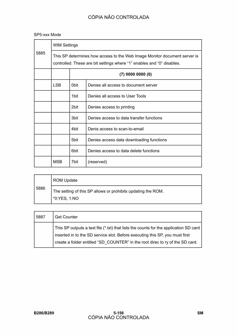
SP5-xxx Mode
B286/B289 5-156 SM
WIM Settings
5885 This SP determines how access to the Web Image Monitor document server is
controlled. These are bit settings where �1� enables and �0� disables.
(7) 0000 0000 (0)
LSB 0bit Denies all access to document server
1bit Denies all access to User Tools
2bit Denies access to printing
3bit Denies access to data transfer functions
4bit Denis access to scan-to-email
5bit Denies access data downloading functions
6bit Denies access to data delete functions
MSB 7bit (reserved)
ROM Update
5886 The setting of this SP allows or prohibits updating the ROM.
*0:YES, 1:NO
5887 Get Counter
This SP outputs a text file (*.txt) that lists the counts for the application SD card
inserted in to the SD service slot. Before executing this SP, you must first
create a folder entitled �SD_COUNTER� in the root direc to ry of the SD card.
CÓPIA NÃO CONTROLADA
CÓPIA NÃO CONTROLADA

SP5-xxx Mode
SM 5-157 B286/B289
Serv
ice
Tabl
es
Plug & Play Maker/Model Name
5907
Selects the brand name and the production name for Windows Plug & Play.
This information is stored in the NVRAM. If the NVRAM is defective, these
names should be registered again.
After selecting, press the �Original Type� key and �#� key at the same time.
When the setting is completed, the beeper sounds five times.
5913 Switchover Permission Time
Sets the length of time to elapse before allowing another application to take
control of the display when the application currently controlling the display is
not operating because a key has not been pressed.
[3~30/3/1 s]
Mechanical Counter Detection
5915
This SP checks the mechanical counter to confirm whether it is connected.
0: Disconnected 1: Connected 2: Unknown
Note:
! The reading returned by this SP does not change if the mechanical counter
is removed while the machine is powered on.
! About 3 sec. is required for this SP to return a correct reading after the
machine is switched on.
5967 Copy Server: Set Function
Disables and enables the document server. This is a security measure that
prevents image data from being left in the temporary file sector of the HDD.
After changing this setting, switch the main switch off and on to enable the new
setting.
[0 to 1/0/1]
0: Enable
1: Disable
CÓPIA NÃO CONTROLADA
CÓPIA NÃO CONTROLADA
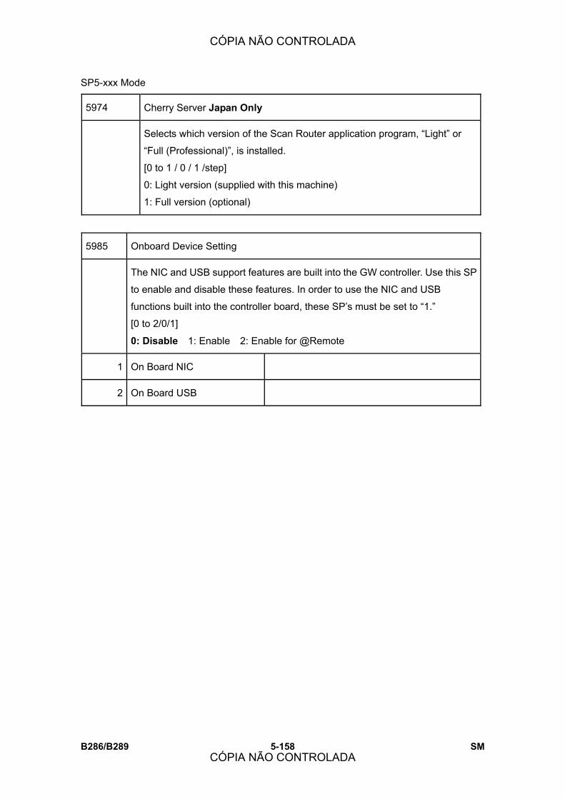
SP5-xxx Mode
B286/B289 5-158 SM
5974 Cherry Server Japan Only
Selects which version of the Scan Router application program, �Light� or
�Full (Professional)�, is installed.
[0 to 1 / 0 / 1 /step]
0: Light version (supplied with this machine)
1: Full version (optional)
5985 Onboard Device Setting
The NIC and USB support features are built into the GW controller. Use this SP
to enable and disable these features. In order to use the NIC and USB
functions built into the controller board, these SP�s must be set to �1.�
[0 to 2/0/1]
0: Disable 1: Enable 2: Enable for @Remote
1 On Board NIC
2 On Board USB
CÓPIA NÃO CONTROLADA
CÓPIA NÃO CONTROLADA
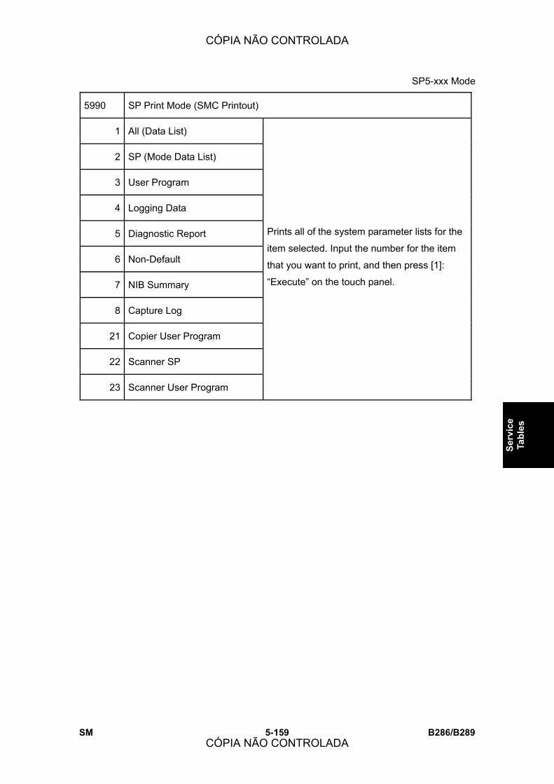
SP5-xxx Mode
SM 5-159 B286/B289
Serv
ice
Tabl
es
5990 SP Print Mode (SMC Printout)
1 All (Data List)
2 SP (Mode Data List)
3 User Program
4 Logging Data
5 Diagnostic Report
6 Non-Default
7 NIB Summary
8 Capture Log
21 Copier User Program
22 Scanner SP
23 Scanner User Program
Prints all of the system parameter lists for the
item selected. Input the number for the item
that you want to print, and then press [1]:
�Execute� on the touch panel.
CÓPIA NÃO CONTROLADA
CÓPIA NÃO CONTROLADA

SP6-xxx Peripherals
B286/B289 5-160 SM
5.12 SP6-XXX PERIPHERALS
6117 Folder Input Check
This SP retrieves the SP settings of each bit within 0.5 sec., collects the data into
1-byte, then sends it to the controller. However, undefined sensor information on
the Folder unit side is set to �0� without checking the Folder unit.
! If there is no response from the Folder FD within the prescribed time after it is
checked, the 1-byte data (sensor information) is set to �0.�
! The requests for engine information stop after this SP screen is closed.
(7) 0000 0000 (1)
1 Fan Folder 1
Bit Input Status
7 Not used ---
6 Not used ---
5 Original width sensor 36 in.
4 Not used ---
3 Entrance sensor 0: No paper, 1: Paper present
2 Not used ---
1 Exit JG sensor 0: No paper, 1: Paper present
0 Not used ---
2 Fan Folder 2
Bit Input Status
7 Original width sensor: 24 in. 0: No paper, 1: Paper present
6 Original width sensor: 18 in. 0: No paper, 1: Paper present
5 Original width sensor: 12 in. 0: No paper, 1: Paper present
CÓPIA NÃO CONTROLADA
CÓPIA NÃO CONTROLADA
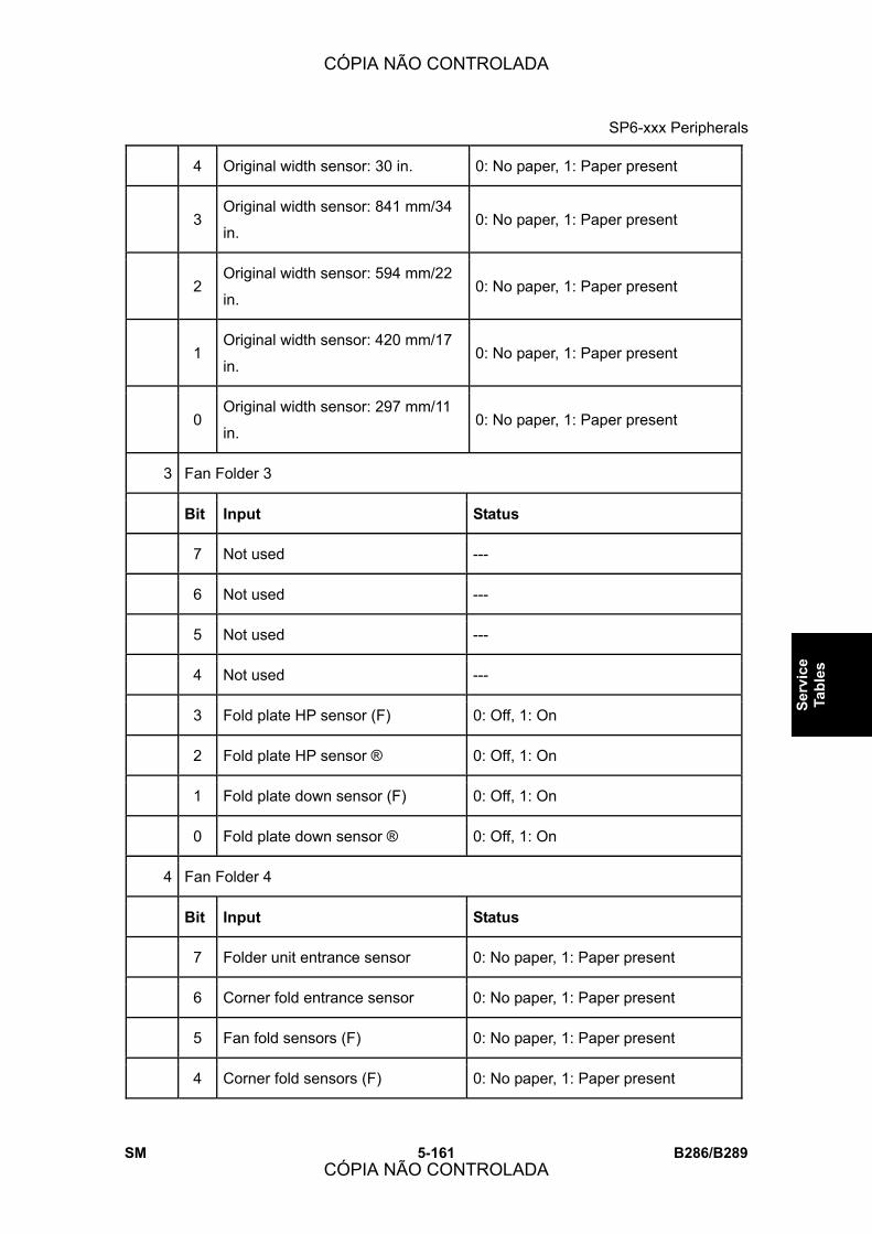
SP6-xxx Peripherals
SM 5-161 B286/B289
Serv
ice
Tabl
es
4 Original width sensor: 30 in. 0: No paper, 1: Paper present
3 Original width sensor: 841 mm/34
in. 0: No paper, 1: Paper present
2 Original width sensor: 594 mm/22
in. 0: No paper, 1: Paper present
1 Original width sensor: 420 mm/17
in. 0: No paper, 1: Paper present
0 Original width sensor: 297 mm/11
in. 0: No paper, 1: Paper present
3 Fan Folder 3
Bit Input Status
7 Not used ---
6 Not used ---
5 Not used ---
4 Not used ---
3 Fold plate HP sensor (F) 0: Off, 1: On
2 Fold plate HP sensor ® 0: Off, 1: On
1 Fold plate down sensor (F) 0: Off, 1: On
0 Fold plate down sensor ® 0: Off, 1: On
4 Fan Folder 4
Bit Input Status
7 Folder unit entrance sensor 0: No paper, 1: Paper present
6 Corner fold entrance sensor 0: No paper, 1: Paper present
5 Fan fold sensors (F) 0: No paper, 1: Paper present
4 Corner fold sensors (F) 0: No paper, 1: Paper present
CÓPIA NÃO CONTROLADA
CÓPIA NÃO CONTROLADA
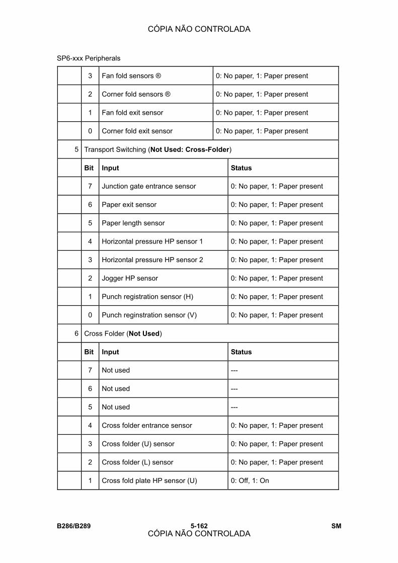
SP6-xxx Peripherals
B286/B289 5-162 SM
3 Fan fold sensors ® 0: No paper, 1: Paper present
2 Corner fold sensors ® 0: No paper, 1: Paper present
1 Fan fold exit sensor 0: No paper, 1: Paper present
0 Corner fold exit sensor 0: No paper, 1: Paper present
5 Transport Switching (Not Used: Cross-Folder)
Bit Input Status
7 Junction gate entrance sensor 0: No paper, 1: Paper present
6 Paper exit sensor 0: No paper, 1: Paper present
5 Paper length sensor 0: No paper, 1: Paper present
4 Horizontal pressure HP sensor 1 0: No paper, 1: Paper present
3 Horizontal pressure HP sensor 2 0: No paper, 1: Paper present
2 Jogger HP sensor 0: No paper, 1: Paper present
1 Punch registration sensor (H) 0: No paper, 1: Paper present
0 Punch reginstration sensor (V) 0: No paper, 1: Paper present
6 Cross Folder (Not Used)
Bit Input Status
7 Not used ---
6 Not used ---
5 Not used ---
4 Cross folder entrance sensor 0: No paper, 1: Paper present
3 Cross folder (U) sensor 0: No paper, 1: Paper present
2 Cross folder (L) sensor 0: No paper, 1: Paper present
1 Cross fold plate HP sensor (U) 0: Off, 1: On
CÓPIA NÃO CONTROLADA
CÓPIA NÃO CONTROLADA

SP6-xxx Peripherals
SM 5-163 B286/B289
Serv
ice
Tabl
es
0 Cross fold plate HP sensor (L) 0: Off, 1: On
7 Invert/Rotate (Not Used: Cross-Folder)
Bit Input Status
7 Not used 0: No paper, 1: Paper present
6 Inverter entrance sensor 0: No paper, 1: Paper present
5 Inverter exit sensor 0: No paper, 1: Paper present
4 Inverter output sensor 0: No paper, 1: Paper present
3 Rotate entrance sensor 0: No paper, 1: Paper present
2 Non-rotate entrance sensor (U) 0: No paper, 1: Paper present
1 Non-rotate entrance sensor (L) 0: No paper, 1: Paper present
0 Paper registration sensor 0: No paper, 1: Paper present
8 Shift Tray (Not Used)
Bit Input Status
7 Not used ---
6 Not used ---
5 Not used ---
4 Exit sensor 0: No paper, 1: Paper present
3 Shift tray HP sensor 0: Off, 1: On
2 Paper sensor 0: No paper, 1: Paper present
1 Lower limit sensor 0: Off, 1: On
0 Door Switch 0: Off, 1: On
9 Punch: Horiz (Not Used)
Bit Input Status
CÓPIA NÃO CONTROLADA
CÓPIA NÃO CONTROLADA

SP6-xxx Peripherals
B286/B289 5-164 SM
7 Not used ---
6 Not used ---
5 Not used ---
4 Not used ---
3 Not used ---
2 Not used ---
1 Punch HP sensor 0: Off, 1: On
0 Punch hopper full sensor 0: Off, 1: On
10 Punch: Vert (Not Used)
Bit Input Status
7 Not used ---
6 Not used ---
5 Not used ---
4 Not used ---
3 Punch unit HP sensor 0: Off, 1: On
2 Punch hopper full sensor 0: Off, 1: On
1 Punch leading edge sensor (V) 0: Off, 1: On
0 Punch HP sensor (V) 0: Off, 1: On
11 Door 1: Fan Folder
Bit Input Status
7 N3 door switch 0: Close, 1: Open
6 N5 door switch 0: Close, 1: Open
5 N6 door switch 0: Close, 1: Open
CÓPIA NÃO CONTROLADA
CÓPIA NÃO CONTROLADA
SP6-xxx Peripherals
SM 5-165 B286/B289
Serv
ice
Tabl
es
4 N7 door switch 0: Close, 1: Open
3 Bypass front cover 0: Close, 1: Open
2 Bypass rear cover 0: Close, 1: Open
1 N6 guide switch (U) 0: Close, 1: Open
0 N6 guide switch (L) 0: Close, 1: Open
12 Door 2: Fan Folder
Bit Input Status
7 Not used ---
6 Not used ---
5 Not used ---
4 Not used ---
3 N1 guide microswitch 0: Close, 1: Open
2 N3 door microswitch 0: Close, 1: Open
1 N5 door microswitch 0: Close, 1: Open
0 Bypass jam door microswitch 0: Close, 1: Open
13 Door 1: Cross Folder
Bit Input Status
7 Not used ---
6 Not used ---
5 Not used ---
4 Not used ---
3 Transport JG door sensor (F) 0: Close, 1: Open
2 Transport JG door sensor (U) 0: Close, 1: Open
CÓPIA NÃO CONTROLADA
CÓPIA NÃO CONTROLADA
SP6-xxx Peripherals
B286/B289 5-166 SM
1 Transport JG door sensor ® 0: Close, 1: Open
0 Cross fold door sensor ® 0: Close, 1: Open
14 Door 2: Cross Folder (Not Used)
Bit Input Status
7 Not used ---
6 Not used ---
5 Not used ---
4 Transport JG door microswitch (F) 0: Close, 1: Open
3 Cross horizontal microswitch 1 0: Close, 1: Open
2 Cross horizontal microswitch 2 0: Close, 1: Open
1 Inverter door microswitch 0: Close, 1: Open
0 Inverter door microswitch 0: Close, 1: Open
6118 Folder Output Check
Use this SP to switch on the motors, clutches, and solenoids of the Folder unit
B889 to test their operation.
Important: After switching on a motor, clutch, or solenoid, be sure to switch it off
after you finish your work.
1 Transport Motor: Fwd: Fan Folder
2 Bypass Feed Clutch: Fan Folder
3 Paper Entrance Clutch: Fan Folder
4 Output Junction Gate SOL: Fan Folder
5 Pre-Fold Motor: SE: Fwd: Fan Folder
6 Pre-Fold Motor: LE Fwd: Fan Folder
7 Pre-Fold Clutch: SE: Fan Folder
CÓPIA NÃO CONTROLADA
CÓPIA NÃO CONTROLADA
SP6-xxx Peripherals
SM 5-167 B286/B289
Serv
ice
Tabl
es
8 Pre-Fold Clutch: LE: Fan Folder
9 Relay Clutch: Fan Folder
10 Corner Fold Exit Clutch: Fan Folder
11 Front Fold Plate: Fan Folder
12 Rear Fold Plate: Fan Folder
13 Fold Motor: Fwd: Fan Folder
14 Fold Motor: Rev: Fan Folder
16 Front Fold Plate Motor: Fwd: Fan Folder
17 Front Fold Plate Motor: Rev: Fan Folder
18 Rear Fold Plate Motor: Fwd: Fan Folder
19 Rear Fold Plate Motor: Rev: Fan Folder
31 Vert Transport Motor: Fwd: Fan Folder
32 Vert Transport Motor: Rev: Fan Folder
33 Jogger Motor: Fwd: Cross Folder
34 Jogger Motor HP Sensor: Cross Folder
35 Punch Transport JG SOL: Cross Folder
36 Horiz Feed Pressure Motor HP Sensor: Cross Folder
38 Vert Feed Pressure SOL 1-3: Cross Folder
39 Horiz Feed Motor: Fwd: Cross Folder
40 Horiz Feed Motor: Rev: Cross Folder
41 Vert Feed Pres Idle SOL 1: L: Cross Folder
42 Vert Feed Pres Idle SOL 2: C: Cross Folder
43 Vert Feed Pres Idle SOL 3: R: Cross Folder
CÓPIA NÃO CONTROLADA
CÓPIA NÃO CONTROLADA
SP6-xxx Peripherals
B286/B289 5-168 SM
44 Fold Motor: Fwd: Cross Folder
45 Fold Motor: Rev: Cross Folder
46 Upper Fold Plate Motor: Fwd: Cross Folder
47 Upper Fold Plate Motor: Rev: Cross Folder
49 Lower Fold Plate Motor: Fwd: Cross Folder
50 Lower Fold Plate Motor: Rev: Cross Folder
51 Fold Plate Motor Position HP Sensor: Cross Folder
52 Inverter Motor: Fwd: Cross Folder
53 Inverter Motor: Rev: Cross Folder
54 Rotate/Transport Motor: Fwd: Cross Folder
55 Inverter Entrance JG SOL: Cross Folder
57 Rotation Sensor SOL: Cross Folder
58 Rotation Entrance Pressure SOL: Cross Folder
59 Rotation Exit Pressure SOL: Cross Folder
60 Rotation Right Pressure SOL: Cross Folder
61 Rotation Left Pressure SOL: Cross Folder
62 Paper Output Motor: Fwd: Cross Folder
63 Shift Tray Motor: Fwd: Cross Folder
64 Tray Lift Motor HP Sensor: Cross Folder
66 Punch Move Motor: Fwd Horiz
67 Punch Move Motor: Rev Horiz
73 Punch Move Motor: Fwd Vert
74 Punch Move Motor: Rev Vert
CÓPIA NÃO CONTROLADA
CÓPIA NÃO CONTROLADA
SP6-xxx Peripherals
SM 5-169 B286/B289
Serv
ice
Tabl
es
75 Punch Drive Motor: Horiz
76 Punch Drive Clutch
6961 Trans. Motor Adj.: Fan Folder - Number of Folder Motor Rotations DFU
This SP adjusts the line-speed of the Folder unit transport motor. The transport
motor drives all the timing belts that turn the rollers in the paper feed path.
[-10 to +10/0/1%]
Note: At �0�, the motor runs at normal speed. Adjustment in the �+� direction
increases speed, and in the �-� direction it decreases speed.
6962 (Fan) Fold Motor Adjustment DFU
Use these SP�s to adjust the fan motor speed to correct skew and offset at the
Folder unit entrance. The fan fold motor drives both pairs of fan fold rollers at the
bottom of the Folder unit.
1 Display Paper Length
This SP displays the length of the paper most recently fed into and folded in the
Folder unit.
[0 to 32767 mm]
One of two sensors detects the leading edge and trailing edge of the paper, and
calculates the paper length based on the length of time for the paper to pass
below:
! On line mode. The Folder unit entrance sensor detects the length of the
paper fed from the main machine.
! Off line mode. The leading edge sensor of the Manual Feeder detects the
length of the paper fed directly into the manual feeder.
CÓPIA NÃO CONTROLADA
CÓPIA NÃO CONTROLADA
SP6-xxx Peripherals
B286/B289 5-170 SM
2 Display Folded Length
This SP displays the length of the paper most recently folded in the Folder unit.
[0 to 32767 mm]
One of two sensors detects the leading edge and trailing edge of the paper, and
calculates the paper length based on the length of time for the paper to pass
below:
! On line mode. The Folder unit entrance sensor detects the length of the
paper fed from the main machine.
! Off line mode. The leading edge sensor of the Manual Feeder detects the
length of the paper fed directly into the manual feeder.
11 (Fan) Fold Roller Speed
The SP sets the default speed of the fan fold roller motor when the man machine
is turned on.
[80 to 160/80/1 mm/s]
21 Skew at Folder Entrance
This SP can be adjusted to correct the reading of the paper length. The input
from SP6962-1 (paper length) and SP6962-22 (paper offset) are used together.
After two sheets of different length have passed, the amount of skew and offset
are calculated then corrected using this equation:
Y = aX + b
where:
X: Actual paper length
Y: Paper length read by machine (SP6962-1)
a: Skew correction (SP6962-21)
b: Offset correction (SP6962-22)
[70 to 130/100/0.1 %]
CÓPIA NÃO CONTROLADA
CÓPIA NÃO CONTROLADA

SP6-xxx Peripherals
SM 5-171 B286/B289
Serv
ice
Tabl
es
22 Offset at Folder Entrance
This SP can be adjusted to correct reading of the paper length. The input from
SP6962-1 (paper length) and SP6962-021 (paper skew) are used together. After
two sheets of different length have passed, the amount of skew and offset are
calculated then corrected using this equation:
Y = aX + b
where:
X: Actual paper length
Y: Paper length read by machine (SP6962-1)
a: Skew correction (SP6962-21)
b: Offset correction (SP6962-22)
[70 to 130/100/0.1 %]
31 Offset at Folder Exit
This SP adjusts the length of the fan folds in the paper to be sent to the cross fold
unit.
[-10 to +10/0/0.1 mm]
41 Fold Motor Rotation
This SP adjusts the rotations of the fan fold motor.
[-10 to +10/0/0.1 %]
CÓPIA NÃO CONTROLADA
CÓPIA NÃO CONTROLADA

SP6-xxx Peripherals
B286/B289 5-172 SM
6963 Fold Plate Adjustment DFU
Use these SP�s to adjust operation of the fold plates inside the fan folder of the
Folder unit.
1 Fold Plate Movement : LEdge
This SP adjusts how far the fold plates descend to guide the leading edge.
[-200 to +200/0/1]
Note:
! An adjustment of 1 step is equivalent to 0.191 mm.
! An adjustment in the �+� direction moves the fold plates closer to the fan fold
rollers, and an adjustment in the �-� direction moves them away from the fan
fold rollers.
2 Fold Plate Movement
This SP adjusts how far the fold plates descend to push the paper between the
fan fold rollers to form the folds.
[-400 to +400/0/1]
Note:
! An adjustment of 1 step is equivalent to 0.191 mm.
! An adjustment in the �+� direction moves the fold plates closer to the fan fold
rollers, and an adjustment in the �-� direction moves them away from the fan
fold rollers.
11 Fold Plate Halt : LEdge
This SP adjusts when the fold plates pause on the downstroke at the lowest point
near the fan fold rollers after the leading edge of the paper has entered the fan
folder mechanism.
[-100 to 500/0/10 ms]
Note: An adjustment in the �+� direction sets a longer time, and an adjustment in
the �-� direction sets a shorter time.
CÓPIA NÃO CONTROLADA
CÓPIA NÃO CONTROLADA

SP6-xxx Peripherals
SM 5-173 B286/B289
Serv
ice
Tabl
es
12 Fold Plate Halt : Folding
This SP adjusts the how long the fold plates pause on the down stroke at its
lowest point near the fan fold rollers.
[-100 to 500/0/10 ms]
Note: An adjustment in the �+� direction sets a longer time, and an adjustment in
the �-� direction sets a shorter time.
21 Fold Plate Timing : LEdge
This SP adjusts the distance the paper feeds past the fan folder entrance sensor
(the sensor goes ON) before the fold plate starts to descend.
[-70 to 70/0/0.1 mm]
Note: An adjustment in the �+� direction lengthens the distance, and an
adjustment in the �-� direction shortens the distance.
22 Fold Plate Timing: Folding
This SP adjusts the distance that the paper travels past the fan fold sensor pair
before the fold plate starts to descend.
[-70 to 70/0/0.1 mm]
Note: An adjustment in the �+� direction lengthens the distance, and an
adjustment in the �-� direction shortens the distance.
31 Fold Plate Movement: LEdge Corner Folding
This SP adjusts the distance that the fan fold plate descends in order to guide the
paper into the fan folding unit for the first fold when corner folding and fan folding
have been selected for the job.
[-200 to +200/0/1 mm]
Note:
! This SP applies only if corner folding the first sheet has been selected for the
job.
! An adjustment of 1 step is equivalent to 0.191 mm.
! An adjustment in the �+� direction moves the fan fold plates closer to the fan
fold rollers, and an adjustment in the �-� direction moves the plate away from
the fan fold rollers.
CÓPIA NÃO CONTROLADA
CÓPIA NÃO CONTROLADA

SP6-xxx Peripherals
B286/B289 5-174 SM
32 Fold Plate Halt: LEdge Corner Folding
This SP adjusts the length of time the paper feeds before the fan fold plate starts
to ascend when corner folding and fan folding have been selected for the job.
[-100 too +500/0/10 mm]
Note:
! This SP applies only if corner folding has also been selected for the job.
! An adjustment in the �+� direction lengthens the time, and an adjustment in
the �-� direction shortens the time.
33 Fold Plate Timing: LEdge Corner Folding
This SP adjusts the distance the paper feeds past the fan folder entrance sensor
(the sensor goes ON) before the fold plate starts to descend when corner folding
is also selected for the job.
[-70 to 70/0/0.1 mm]
Note:
! This adjustment applies only after corner folding is also selected for the job.
! An adjustment in the �+� direction lengthens the distance, and an adjustment
in the �-� direction shortens the distance.
41 Fold Plate Movement: Paper Exit
This SP adjusts the distance for the fan fold plate to move in order to guide the
trailing edge of the last fold out of the fan folder unit.
[-200 to +200/0/1 mm]
Note:
! An adjustment of 1 step is equivalent to 0.191 mm.
! An adjustment in the �+� direction moves the fan fold plates closer to the fan
fold rollers, and an adjustment in the �-� direction moves the plate away from
the fan fold rollers.
CÓPIA NÃO CONTROLADA
CÓPIA NÃO CONTROLADA

SP6-xxx Peripherals
SM 5-175 B286/B289
Serv
ice
Tabl
es
42 Fold Plate Halt: Paper Exit
This SP adjusts the length of time that the fan fold plate stops after descending in
order to output trailing edge of the folded copy out of the folder unit after the last
fold.
[-100 to +6000/0/1 msec.]
Note: An adjustment in the �+� direction lengthens the time, and an adjustment in
the �-� direction shortens the time.
43 Fold Plate Timing: Paper Exit
This SP adjusts distance that the paper moves after the fan fold sensor pair
detects the trailing edge and switches ON until the fan fold plate starts to move
when feeding the copy out of the folder unit after the last fold.
[0 to 350/0/1 mm]
Note: An adjustment in the �+� direction lengthens the distance, and an
adjustment in the �-� shortens the distance.
CÓPIA NÃO CONTROLADA
CÓPIA NÃO CONTROLADA
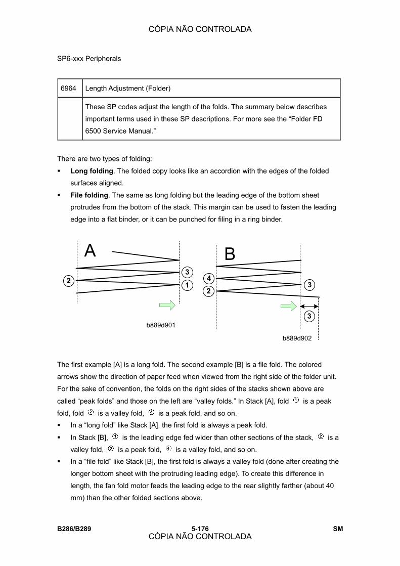
SP6-xxx Peripherals
B286/B289 5-176 SM
6964 Length Adjustment (Folder)
These SP codes adjust the length of the folds. The summary below describes
important terms used in these SP descriptions. For more see the �Folder FD
6500 Service Manual.�
There are two types of folding:
! Long folding. The folded copy looks like an accordion with the edges of the folded
surfaces aligned.
! File folding. The same as long folding but the leading edge of the bottom sheet
protrudes from the bottom of the stack. This margin can be used to fasten the leading
edge into a flat binder, or it can be punched for filing in a ring binder.
The first example [A] is a long fold. The second example [B] is a file fold. The colored
arrows show the direction of paper feed when viewed from the right side of the folder unit.
For the sake of convention, the folds on the right sides of the stacks shown above are
called �peak folds� and those on the left are �valley folds.� In Stack [A], fold is a peak
fold, fold is a valley fold, is a peak fold, and so on.
! In a �long fold� like Stack [A], the first fold is always a peak fold.
! In Stack [B], is the leading edge fed wider than other sections of the stack, is a
valley fold, is a peak fold, is a valley fold, and so on.
! In a �file fold� like Stack [B], the first fold is always a valley fold (done after creating the
longer bottom sheet with the protruding leading edge). To create this difference in
length, the fan fold motor feeds the leading edge to the rear slightly farther (about 40
mm) than the other folded sections above.
b889d901
b889d902
23
14
23
3
CÓPIA NÃO CONTROLADA
CÓPIA NÃO CONTROLADA
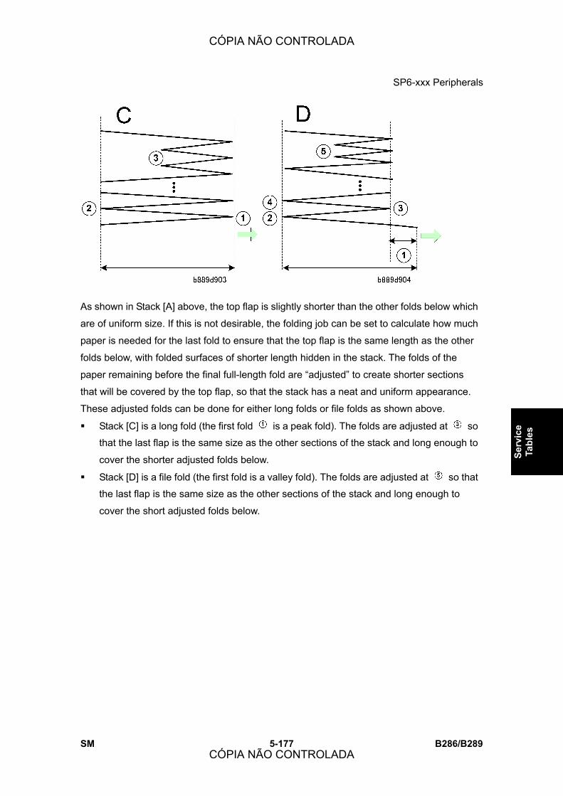
SP6-xxx Peripherals
SM 5-177 B286/B289
Serv
ice
Tabl
es
As shown in Stack [A] above, the top flap is slightly shorter than the other folds below which
are of uniform size. If this is not desirable, the folding job can be set to calculate how much
paper is needed for the last fold to ensure that the top flap is the same length as the other
folds below, with folded surfaces of shorter length hidden in the stack. The folds of the
paper remaining before the final full-length fold are �adjusted� to create shorter sections
that will be covered by the top flap, so that the stack has a neat and uniform appearance.
These adjusted folds can be done for either long folds or file folds as shown above.
! Stack [C] is a long fold (the first fold is a peak fold). The folds are adjusted at so
that the last flap is the same size as the other sections of the stack and long enough to
cover the shorter adjusted folds below.
! Stack [D] is a file fold (the first fold is a valley fold). The folds are adjusted at so that
the last flap is the same size as the other sections of the stack and long enough to
cover the short adjusted folds below.
CÓPIA NÃO CONTROLADA
CÓPIA NÃO CONTROLADA
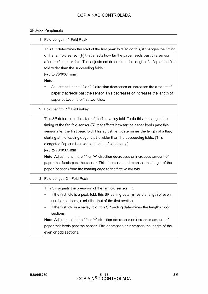
SP6-xxx Peripherals
B286/B289 5-178 SM
1 Fold Length: 1st Fold Peak
This SP determines the start of the first peak fold. To do this, it changes the timing
of the fan fold sensor (F) that affects how far the paper feeds past this sensor
after the first peak fold. This adjustment determines the length of a flap at the first
fold wider than the succeeding folds.
[-70 to 70/0/0.1 mm]
Note:
! Adjustment in the �-� or �+� direction decreases or increases the amount of
paper that feeds past the sensor. This decreases or increases the length of
paper between the first two folds.
2 Fold Length: 1st Fold Valley
This SP determines the start of the first valley fold. To do this, it changes the
timing of the fan fold sensor (R) that affects how far the paper feeds past this
sensor after the first peak fold. This adjustment determines the length of a flap,
starting at the leading edge, that is wider than the succeeding folds. (This
elongated flap can be used to bind the folded copy.)
[-70 to 70/0/0.1 mm]
Note: Adjustment in the �-� or �+� direction decreases or increases amount of
paper that feeds past the sensor. This decreases or increases the length of the
paper (section) from the leading edge to the first valley fold.
3 Fold Length: 2nd Fold Peak
This SP adjusts the operation of the fan fold sensor (F).
! If the first fold is a peak fold, this SP setting determines the length of even
number sections, excluding that of the first section.
! If the first fold is a valley fold, this SP setting determines the length of odd
sections.
Note: Adjustment in the �-� or �+� direction decreases or increases amount of
paper that feeds past the sensor. This decreases or increases the length of the
even or odd sections.
CÓPIA NÃO CONTROLADA
CÓPIA NÃO CONTROLADA

SP6-xxx Peripherals
SM 5-179 B286/B289
Serv
ice
Tabl
es
4 Fold Length: 2nd Fold Valley
This SP adjusts the operation of the fan fold sensor (R).
! If the first fold is a peak fold, this SP setting determines the length of odd
number sections.
! If the first fold is a valley fold, this SP setting determines the length of even
sections, excluding that of the first section.
Note: Adjustment in the �-� or �+� direction decreases or increases amount of
paper that feeds past the sensor. This decreases or increases the length of the
even or odd sections.
11 Margin Fold Length: 3rd Fold: A0 SEF
This SP adjusts the length of the 3rd section when folding A0 SEF paper.
[-20 to +20/-2.5/01. mm]
Note: Adjustment in the �-� or �+� direction decreases or increases the length of
the 3rd section.
12 Margin Fold Length: 5th Fold A0 SEF
This SP adjusts the length of the 5th section when folding A0 SEF paper.
[-20 to +20/-3/01. mm]
Note: Adjustment in the �-� or �+� direction decreases or increases the length of
the 5th section.
13 Margin Fold Length: 3rd Fold: A1 SEF
This SP adjusts the length of the 3rd section when folding A1 SEF paper.
[-20 to +20/-1.5/01. mm]
Note: Adjustment in the �-� or �+� direction decreases or increases the length of
the 3rd section.
14 Margin Fold Length: 3rd Fold: A2 SEF
This SP adjusts the length of the 3rd section when folding A2 SEF paper.
[-20 to +20/-6/01. mm]
Note: Adjustment in the �-� or �+� direction decreases or increases the length of
the 3rd section.
CÓPIA NÃO CONTROLADA
CÓPIA NÃO CONTROLADA
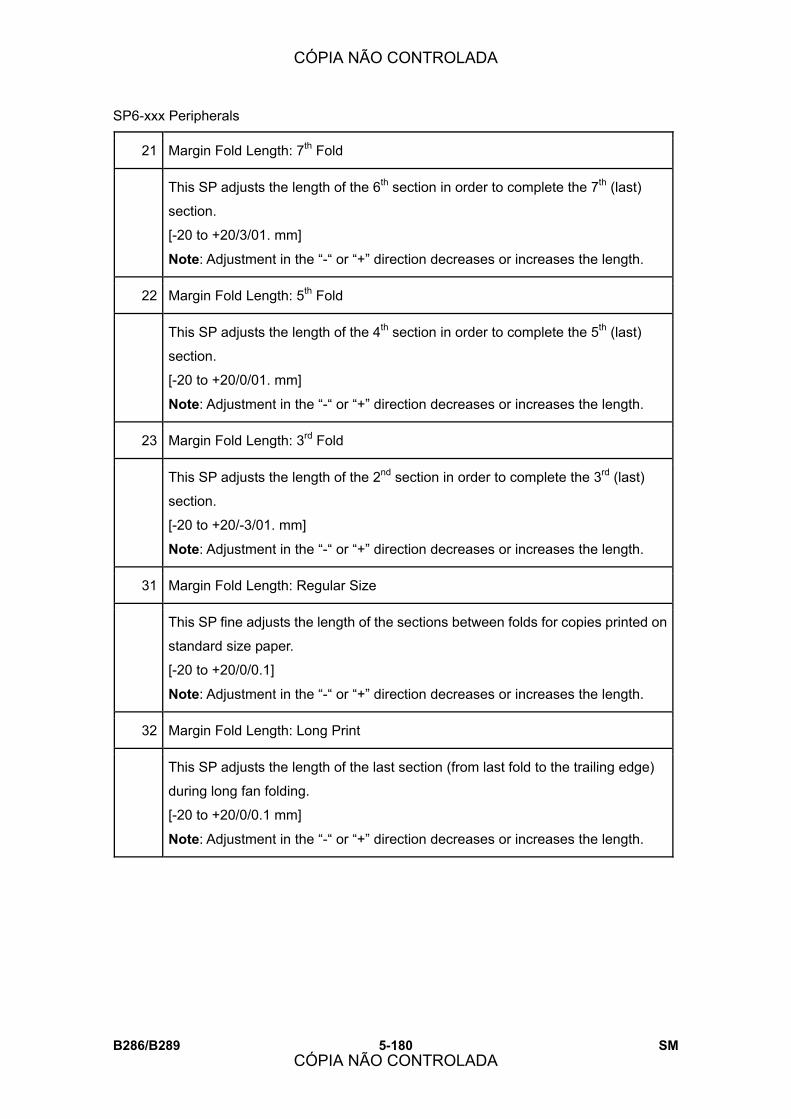
SP6-xxx Peripherals
B286/B289 5-180 SM
21 Margin Fold Length: 7th Fold
This SP adjusts the length of the 6th section in order to complete the 7th (last)
section.
[-20 to +20/3/01. mm]
Note: Adjustment in the �-� or �+� direction decreases or increases the length.
22 Margin Fold Length: 5th Fold
This SP adjusts the length of the 4th section in order to complete the 5th (last)
section.
[-20 to +20/0/01. mm]
Note: Adjustment in the �-� or �+� direction decreases or increases the length.
23 Margin Fold Length: 3rd Fold
This SP adjusts the length of the 2nd section in order to complete the 3rd (last)
section.
[-20 to +20/-3/01. mm]
Note: Adjustment in the �-� or �+� direction decreases or increases the length.
31 Margin Fold Length: Regular Size
This SP fine adjusts the length of the sections between folds for copies printed on
standard size paper.
[-20 to +20/0/0.1]
Note: Adjustment in the �-� or �+� direction decreases or increases the length.
32 Margin Fold Length: Long Print
This SP adjusts the length of the last section (from last fold to the trailing edge)
during long fan folding.
[-20 to +20/0/0.1 mm]
Note: Adjustment in the �-� or �+� direction decreases or increases the length.
CÓPIA NÃO CONTROLADA
CÓPIA NÃO CONTROLADA

SP6-xxx Peripherals
SM 5-181 B286/B289
Serv
ice
Tabl
es
41 Long Print: 1st Fold Peak: After 2nd Fold
This SP modifies the operation of the fan fold sensor (F) to determine the lengths
of the odd and even sections for long fan folding only.
! If the first fold is a peak fold, this SP setting determines the length of even
number sections, excluding the 1st section.
! If the first fold is a valley fold, this SP setting determines the length of odd
sections.
Note: Adjustment in the �-� or �+� direction decreases or increases the length.
42 Long Print: 1st Fold Valley: After 2nd Fold
This SP modifies the operation of the fan fold sensor (R) to determine the lengths
of the odd and even sections for long fan folding.
! If the first fold is a peak fold, this SP setting determines the length of odd
number sections, excluding the 1st section.
! If the first fold is a valley fold, this SP setting determines the length of even
sections.
Note: Adjustment in the �-� or �+� direction decreases or increases the length.
43 Margin Fold: 1st Fold Peak: After 4th Fold
This SP modifies the operation of the fan fold sensor (F) to determine the lengths
of the odd and even sections for long fan folding (including file flap or margin
folding).
! If the first fold is a peak fold, this SP setting determines the length even
number sections, excluding the 1st section.
! If the first fold is a valley fold, this SP setting determines the length of odd
sections.
Note: Adjustment in the �-� or �+� direction decreases or increases the length.
44 Margin Fold: 1st Fold Valley: After 2nd Fold
CÓPIA NÃO CONTROLADA
CÓPIA NÃO CONTROLADA

SP6-xxx Peripherals
B286/B289 5-182 SM
This SP modifies the operation of the fan fold sensor (R) to determine the lengths
of the odd and even sections for long fan folding) including file flap folding).
! If the first fold is a peak fold, this SP setting determines the length even
number sections.
! If the first fold is a valley fold, this SP setting determines the length of odd
sections, excluding the 1st section.
Note: Adjustment in the �-� or �+� direction decreases or increases the length.
45 Fold Length: 1st Fold Peak: A3 SEF
This SP fine adjusts the length of the sections between folds for copies printed on
A3 SEF paper.
[-20 to +20/0/0.1]
Note: Adjustment in the �-� or �+� direction decreases or increases the length.
51 Margin Fold Length: File
This SP fine adjusts the calculated length of the file flap.
[-20 to +20/0/0.1]
61 Margin Fold Length: Threshold
This SP adjusts the threshold variable that the machine uses to calculate when to
do adjusted folding.
[-70 to +70/0/0.1]
91 Regular Size Fold Switching
This SP determines whether the lengths of the sections can be adjusted for
folding standard paper sizes.
[0 to 1/0/1]
0: Adjustment allowed
1: Adjustment not allowed
6965 Pre-Fold Adjustment (Corner Folder) Not Used
CÓPIA NÃO CONTROLADA
CÓPIA NÃO CONTROLADA

SP6-xxx Peripherals
SM 5-183 B286/B289
Serv
ice
Tabl
es
6966 Fan Fold Selection: Fan Folder Standard Fold Switching
This SP determines whether fixed pattern printing only is enabled when the
Folder unit is online.
[0 to 1/0/1]
0: Disable
1: Enable fixed pattern only
6969 Bypass Feed Setting DFU
This sets the how the bypass feed sensors read paper sizes.
[0 to 1/0/1]
0: DOM, EU (Japan, Europe)
1: NA (North America)
6971 Transport Switch Adj (Cross Folder) Not Used
6972 Cross Fold Adjustment (Cross Folder) Not Used
6973 Invert/Rotate Adjustment (Cross Folder) Not Used
6974 Shift Tray Adjustment: Cross Wait Position (Cross Folder) Not Used
CÓPIA NÃO CONTROLADA
CÓPIA NÃO CONTROLADA

SP6-xxx Peripherals
B286/B289 5-184 SM
6991 Folder Counter
These SP�s display the operational counts for the functions in the fan fold, cross
punch, and transport and folding unit. This SP�s display the counts for each item
listed below in the range: 0 to 9999 9999,
1 Fan Folder Sheet Count Number of sheets through the fan folder
(with or without folding)
2 Cross Folder Sheet Count Number of sheets through the cross folder
unit (with or without folding)
3 Fan Fold Count Number of folds done by fan folder.
4 Corner Fold Count Number of folds done by corner folder.
5 Cross Fold Count Number of folds done by cross folder.
6 Punch Count (Vert) Number of vertical punches (2 holes
across direction of feed)
7 Punch Count (Horiz) Number of vertical punches (2 holes
parallel to direction of feed)
CÓPIA NÃO CONTROLADA
CÓPIA NÃO CONTROLADA
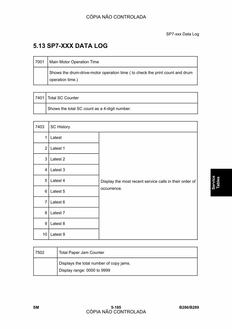
SP7-xxx Data Log
SM 5-185 B286/B289
Serv
ice
Tabl
es
5.13 SP7-XXX DATA LOG
7001 Main Motor Operation Time
Shows the drum-drive-motor operation time ( to check the print count and drum
operation time.)
7401 Total SC Counter
Shows the total SC count as a 4-digit number.
7403 SC History
1 Latest
2 Latest 1
3 Latest 2
4 Latest 3
5 Latest 4
6 Latest 5
7 Latest 6
8 Latest 7
9 Latest 8
10 Latest 9
Display the most recent service calls in their order of
occurrence.
7502 Total Paper Jam Counter
Displays the total number of copy jams.
Display range: 0000 to 9999
CÓPIA NÃO CONTROLADA
CÓPIA NÃO CONTROLADA

SP7-xxx Data Log
B286/B289 5-186 SM
7503 Total Original Jam Counter
Displays the total number of original jams.
Display range: 0000 to 9999
Paper Jam Counter by Jam Location
Displays the total number of copy jams by location.
A �Paper Late� error occurs when the paper fails to activate the sensor at
the precise time. A �Paper Lag� paper jam occurs when the paper remains
at the sensor for longer than the prescribed time.
Display range: 0000 to 9999
Main Machine
1: At Power On Main Machine (B286)
3: Tray 1: No Feed
4: Tray 2: No Feed
5: Tray 3: No Feed
8: RF Exit Sn: Not On
13: Reg Sn: Not On
16: Exit Sn: Not On
34: Bypass: No Feed
53: Tray 1: Paper Lag
54: Tray 2: Paper Lag
55: Tray 3: Paper Lag
58: RF Exit Sn: Not Off
63: Reg Sn: Not Off
7504:
66: Exit Sn: Not Off
CÓPIA NÃO CONTROLADA
CÓPIA NÃO CONTROLADA

SP7-xxx Data Log
SM 5-187 B286/B289
Serv
ice
Tabl
es
84: Bypass Sn: Not Off
Folder FD Unit (B889)
100: Folder: At Power On
130: Bypass Ent Sn: Not On
131: Bypass Relay Sn: Not Off
132: Straight Exit Sn: Not On
133: Straight Exit Sn: Not Off
134: Folder Relay Sn: Not On
135: Folder Relay Sn: Not Off
136: Corner Folder Exit Sn: Not On
137: Corner Folder Exit Sn: Not Off
138: Accordion Folder Ent Sn: Not On
139: Folder Ent Sn: Not Off
140: Front Fold Width Sn: Not On
141: Rear Fold Width Sn: Not On
142: Rear Fold Width Sn: Not Off
143: Accordion Folder Exit Sn: Not On
144: Folder Exit Sn: Not Off
145: Maximum Paper Length
146: Fold Count Limit
Cross Folder
150: Cross Folder: At Power On Not used
170: Trans Unit Ent Sn: Not On Not used
CÓPIA NÃO CONTROLADA
CÓPIA NÃO CONTROLADA

SP7-xxx Data Log
B286/B289 5-188 SM
171: Trans Unit Ent Sn: Not Off Not used
172: Punch Reg Sn (Vert): Not On Not used
173: Punch Reg Sn (Horiz): Not On Not used
174: Trans Uniti Exit Sn: Not On Not used
175: Paper Exit Sn: Not Off Not used
176: Long Paper Exit Sn: Not On Not used
177: Paper Length Sn: Not Off Not used
178: Cross Folder Ent Sn: Not On Not used
179: Cross Folder Ent Sn: Not Off Not used
180: Fold Width Sn (Upper): Not On Not used
181: Fold Width Sn (Lower): Not On Not used
182: Folder Width Sn (Up): Not Off Not used
183: Inverter Ent Sn: Not On Not used
184: Inverter Ent Sn: Not Off Not used
185: Inverter Exit Sn: Not On Not used
186: Inverter Exit Sn: Not Off Not used
187: Inverter Output Sn: Not Off Not used
188: Rotation Ent Sn: Not On Not used
189: Rotation Ent Sn: Not Off Not used
190: No Rotation Sn Not used
191: Rotation Exit Sn: Not On Not used
192: Rotation Exit Sn: Not Off Not used
193: Cross Folder Exit Sn: Not On Not used
CÓPIA NÃO CONTROLADA
CÓPIA NÃO CONTROLADA
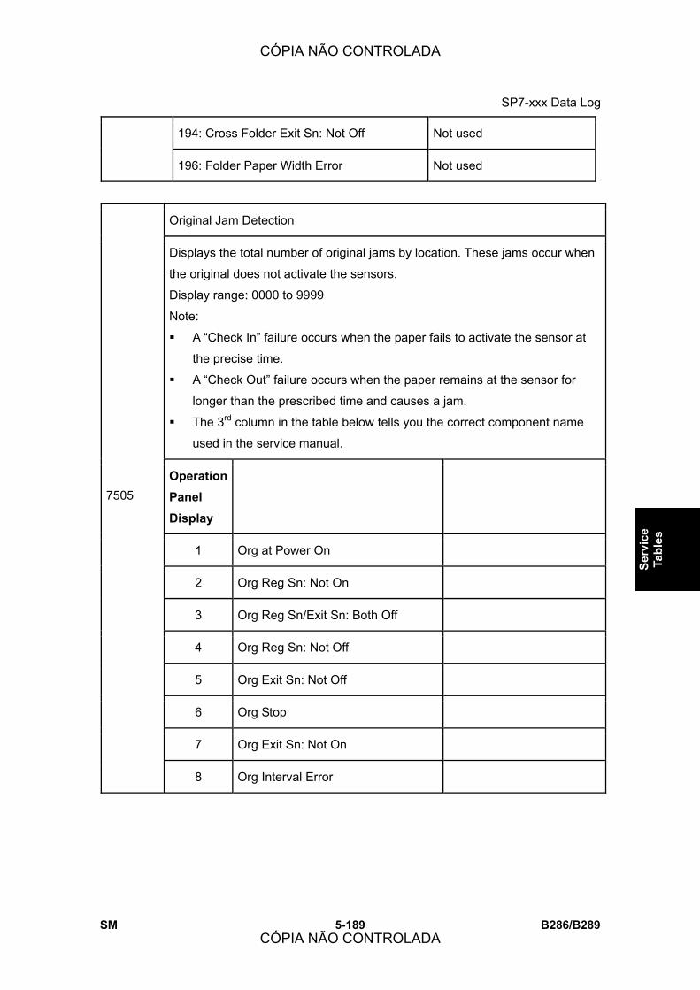
SP7-xxx Data Log
SM 5-189 B286/B289
Serv
ice
Tabl
es
194: Cross Folder Exit Sn: Not Off Not used
196: Folder Paper Width Error Not used
Original Jam Detection
Displays the total number of original jams by location. These jams occur when
the original does not activate the sensors.
Display range: 0000 to 9999
Note:
! A �Check In� failure occurs when the paper fails to activate the sensor at
the precise time.
! A �Check Out� failure occurs when the paper remains at the sensor for
longer than the prescribed time and causes a jam.
! The 3rd column in the table below tells you the correct component name
used in the service manual.
Operation Panel Display
1 Org at Power On
2 Org Reg Sn: Not On
3 Org Reg Sn/Exit Sn: Both Off
4 Org Reg Sn: Not Off
5 Org Exit Sn: Not Off
6 Org Stop
7 Org Exit Sn: Not On
7505
8 Org Interval Error
CÓPIA NÃO CONTROLADA
CÓPIA NÃO CONTROLADA
SP7-xxx Data Log
B286/B289 5-190 SM
7506 Jam Count by Paper Size
This SP displays the counts for the number of jams by paper size.
Note: In the paper size notations below, �T� means �SEF� (Short Edge Feed).
97 A0T/A1
98 A1T/A2
99 A2T/A3
100 A3T/A4
101 A4T
106 B1T/B2
107 B2T/B3
108 B3T/B4
109 B4T
225 36x48T/24x36
226 24x36T/18x24
227 18x24T/12x18
228 12x18T/9x12
229 9x127
234 34x44T/22x34
235 22x34T/17x22
236 17x22T/11x17
237 11x17T/8.5x11
238 8.5x11T
255 Others
CÓPIA NÃO CONTROLADA
CÓPIA NÃO CONTROLADA

SP7-xxx Data Log
SM 5-191 B286/B289
Serv
ice
Tabl
es
Plotter Jam History
7507
Displays the copy jam history in groups of 10, starting with the most recent 10
jams. Display contents are as follows:
CODE: SP7-505-*** number.
SIZE: Paper size code in hex. (See the table below.)
TOTAL :Total jam error count (SP7003)
DATE: Previous jam occurred
1 Latest
2 Latest 1
3 Latest 2
4 Latest 3
5 Latest 4
6 Latest 5
7 Latest 6
8 Latest 7
9 Latest 8
10 Latest 9
Sample Display:
CODE: 007
SIZE: 05h
TOTAL: 0000334
DATE: Mon Mar 15 11:44:50 2000
Original Jam History
7508
Displays the original jam history in groups of 10, starting with the most
recent 10 jams. Display contents are as follows:
CODE: SP7505-*** number.
SIZE: Paper size code in hex. (See table below.)
TOTAL: Total jam error count (SP7003)
DATE: Date the previous jam occurred
1 Latest
2 Latest 1
Sample Display:
CODE: 007
CÓPIA NÃO CONTROLADA
CÓPIA NÃO CONTROLADA
SP7-xxx Data Log
B286/B289 5-192 SM
3 Latest 2
4 Latest 3
5 Latest 4
6 Latest 5
7 Latest 6
8 Latest 7
9 Latest 8
10 Latest 9
SIZE: 05h
TOTAL: 0000334
DATE: Mon Mar 15 11:44:50 2000
Paper Size Hex Codes
These codes are displayed by SP7507 and SP7508.
Paper Size Code (hex) Paper Size Code (hex)
A4 LEF 05 B4 SEF 8D
A5 LEF 06 B5 SEF 8E
LT LEF 26 DLT SEF A0
A3 SEF 84 LG SEF A4
A4 SEF 85 LT SEF A6
A5 SEF 86 Others FF
7801 ROM Version
Displays the ROM number, firmware version numbers, and other important
information about the machine. Press ' or * to see more information.
7803 PM Counter Display
Displays the PM counter since the last PM.
CÓPIA NÃO CONTROLADA
CÓPIA NÃO CONTROLADA
SP7-xxx Data Log
SM 5-193 B286/B289
Serv
ice
Tabl
es
7804 PM Counter Reset
Resets the PM counter. To reset, press [Execute]
SC/Jam Counter Reset
7807 Resets the SC and jam counters. To reset, press [Execute]. This SP does not
reset the jam history counters: SP7507, SP7508.
MF Error Counter Japan Only 7826
Displays the number of counts requested of the card/key counter.
1 Error Total A request for the count total failed at power on. This error
will occur if the device is installed but disconnected.
2 Error Staple The request for a staple count failed at power on. This error
will occur if the device is installed but disconnected.
MF Error Counter Clear 7827
Press [Execute] to reset the values of SP7826 to �0.� Japan Only
Self-Diagnosis Result Display
7832 Opens the �Self-Diagnose Result Display� to view details about errors. Use the
keys on in the display to scroll through all the information. If no errors have
occurred, you will see �No Error.�
7833 Pixel Coverage
Displays the coverage ratio of the output (the ratio of the total pixel area of the
image data to the total printable area on the paper).
Note
! This value is not directly proportional to the amount of toner consumed.
! It is, however, one factor that affects this amount.
CÓPIA NÃO CONTROLADA
CÓPIA NÃO CONTROLADA

SP7-xxx Data Log
B286/B289 5-194 SM
! Other major factors include: the type, total image area and image density of
the original, toner concentration and developer potential.
1 Last Page 0% to 100%.
2 Accumulated Average 0% to 100%.
3 Total Toner Cartridges Used 0 to 65,535 copies
4 Previous Toner Bottle 0 to 999,999 copies
5 Toner Bottle Before Previous 0 to 999,999 copies
7834 Coverage Data Clear
These SPs clear the counters for the following items.
1 Last & Average
2 Total Toner Cartridges Used
3 Toner Cartridge Count: Last & Before Last
4 Page Counts
255 All Clear
Total Memory Size 7836
Displays the memory capacity of the controller system: �1024 MB.�
CÓPIA NÃO CONTROLADA
CÓPIA NÃO CONTROLADA
SP7-xxx Data Log
SM 5-195 B286/B289
Serv
ice
Tabl
es
7901 Assert Info.
These SP numbers display the results of the occurrence of the most recent SC
code generated by the machine.
1 File Name Module name
2 Number of Lines Lines where error occurred.
3 Location Component affected by error
7999 Engine Debug Log Switch DFU
Allows selection of the log to save with the debug log switch.
[0 to 100/0/1]
CÓPIA NÃO CONTROLADA
CÓPIA NÃO CONTROLADA
SP8-xxx Data Log 2
B286/B289 5-196 SM
5.14 SP8-XXX DATA LOG 2
Here are some Group 8 SP�s that when used in combination with others can provide useful
information.
SP Numbers What They Do
SP8211 to SP8216 The number of pages scanned to the document server.
SP8401 to SP8406 The number of pages printed from the document server
SP8691 to SP8696 The number of pages sent from the document server
Specifically, the following questions can be answered:
! How is the document server actually being used?
! What application is using the document server most frequently?
! What data in the document server is being reused?
The SP�s in this group are prefixed with a letter that indicates the mode of operation (the
mode of operation is referred to as an �application�). Before reading the Group 8 Service
Table, make sure that you understand what these prefixes mean.
Prefix What It Means
T: Total: (Grand Total). Grand total of the items counted for all
applications (C, F, P, etc.)..
C: Copy application.
P: Print application.
S: Scan application.
Totals (pages, jobs, etc.) executed for each
application when the job was not stored on the
document server.
CÓPIA NÃO CONTROLADA
CÓPIA NÃO CONTROLADA

SP8-xxx Data Log 2
SM 5-197 B286/B289
Serv
ice
Tabl
es
L: Local storage (document
server)
Totals (jobs, pages, etc.) for the document
server. The L: counters work differently case by
case. Sometimes, they count jobs/pages stored
on the document server; this can be in document
server mode (from the document server
window), or from another mode, such as from a
printer driver or by pressing the Store File button
in the Copy mode window. Sometimes, they
include occasions when the user uses a file that
is already on the document server. Each counter
will be discussed case by case.
O:
Other applications
(external network
applications, for
example)
Refers to network applications such as Web
Image Monitor. Utilities developed with the SDK
(Software Development Kit) will also be counted
with this group in the future.
The Group 8 SP codes are limited to 17 characters, forced by the necessity of displaying
them on the smaller LCD�s of copiers, printers and faxes that also use these SP�s. Read
over the list of abbreviations below and refer to it again if you see the name of an SP that
you do not understand.
Key for Abbreviations
Abbreviation What It Means
/ �By�, e.g. �T:Jobs/Apl� = Total Jobs �by� Application
> More (2> �2 or more�, 4> �4 or more�
AddBook Address Book
Apl Application
B/W Black & White
Bk Black
C Cyan
CÓPIA NÃO CONTROLADA
CÓPIA NÃO CONTROLADA

SP8-xxx Data Log 2
B286/B289 5-198 SM
Abbreviation What It Means
ColCr Color Create
ColMode Color Mode
Comb Combine
Comp Compression
Deliv Delivery
DesApl Designated Application. The application (Copy, Fax, Scan, Print)
used to store the job on the document server, for example.
Dev Counter Development Count, no. of pages developed.
Dup, Duplex Duplex, printing on both sides
Emul Emulation
FC Full Color
FIN Post-print processing, i.e. finishing (punching, stapling, etc.)
Full Bleed No Margins
GenCopy Generation Copy Mode
GPC
Get Print Counter. For jobs 10 pages or less, this counter does not
count up. For jobs larger than 10 pages, this counter counts up by
the number that is in excess of 10 (e.g., for an 11-page job, the
counter counts up 11-10 =1)
IFax Internet Fax
ImgEdt Image Edit performed on the original with the copier GUI, e.g.
border removal, adding stamps, page numbers, etc.
K Black (YMCK)
LS Local Storage. Refers to the document server.
LSize Large (paper) Size
CÓPIA NÃO CONTROLADA
CÓPIA NÃO CONTROLADA

SP8-xxx Data Log 2
SM 5-199 B286/B289
Serv
ice
Tabl
es
Abbreviation What It Means
Mag Magnification
MC One color (monochrome)
NRS
New Remote Service, which allows a service center to monitor
machines remotely. �NRS� is used overseas, �CSS� is used in
Japan.
Org Original for scanning
OrgJam Original Jam
Palm 2
Print Job Manager/Desktop Editor: A pair of utilities that allows print
jobs to be distributed evenly among the printers on the network,
and allows files to moved around, combined, and converted to
different formats.
PC Personal Computer
PGS
Pages. A page is the total scanned sursection of the original.
Duplex pages count as two pages, and A3 simplex count as two
pages if the A3/DLT counter SP is switched ON.
PJob Print Jobs
Ppr Paper
PrtJam Printer (plotter) Jam
PrtPGS Print Pages
Rez Resolution
SC Service Code (Error SC code displayed)
Scn Scan
Sim, Simplex Simplex, printing on 1 side.
CÓPIA NÃO CONTROLADA
CÓPIA NÃO CONTROLADA

SP8-xxx Data Log 2
B286/B289 5-200 SM
S- to -Email Scan- to -E-mail
SMC SMC report printed with SP5990. All of the Group 8 counters are
recorded in the SMC report.
Svr Server
tonEnd toner End
tonSave toner Save
TXJob Send, Transmission
YMC Yellow, Magenta, Cyan
YMCK Yellow, Magenta, Cyan, BlacK
All of the Group 8 SP�s are reset with SP5 801 1 Memory All Clear,
or the counter reset SP7 808.
8001 T:Total Jobs
8002 C:Total Jobs
8004 P:Total Jobs
8005 S:Total Jobs
8006 L:Total Jobs
These SP�s count the number of times each
application is used to do a job.
[0 to 9999999/ 0 / 1]
Note: The L: counter is the total number of times
the other applications are used to send a job to
the document server, plus the number of times a
file already on the document server is used.
! These SP�s reveal the number of times an application is used, not the number of pages
processed.
! When an application is opened for image input or output, this counts as one job.
! Interrupted jobs (paper jams, etc.) are counted, even though they do not finish.
! Only jobs executed by the operator are counted. Jobs executed by the operator
engineer using the SP modes are not counted.
! When using secure printing (when a password is required to start the print job), the job
is counted at the time when either �Delete Data� or �Specify Output� is specified.
! When a copy job on the document server is printed, SP8022 also increments, and
when a print job stored on the document server is printed, SP8024 also increments.
CÓPIA NÃO CONTROLADA
CÓPIA NÃO CONTROLADA

SP8-xxx Data Log 2
SM 5-201 B286/B289
Serv
ice
Tabl
es
! When an original is both copied and stored on the document server, the C: and L:
counters both increment.
! When a print job is stored on the document server, only the L: counter increments.
! When the user presses the Document Server but to n to store the job on the document
server, only the L: counter increments.
! When the user enters document server mode and prints data s to red on the document
server, only the L: counter increments.
! When an image received from Palm 2 is received and stored, the L: counter
increments.
! When the operator prints a report (user code list, for example), the O: counter
increments.
8011 T:Jobs/LS
8012 C:Jobs/LS
8014 P:Jobs/LS
8015 S:Jobs/LS
8016 L:Jobs/LS
8017 O:Jobs/LS
These SP�s count the number of jobs stored to
the document server by each application, to
reveal how local storage is being used for input.
[0 to 9999999/ 0 / 1]
The L: counter counts the number of jobs stored
from within the document server mode screen at
the operation panel.
! When a scan job is sent to the document server, the S: counter increments. When you
enter document server mode and then scan an original, the L: counter increments.
! When a print job is sent to the document server, the P: counter increments.
! When a network application sends data to the document server, the O: counter
increments.
! When an image from Palm 2 is stored on the document server, the O: counter
increments.
CÓPIA NÃO CONTROLADA
CÓPIA NÃO CONTROLADA

SP8-xxx Data Log 2
B286/B289 5-202 SM
8021 T:Pjob/LS
8022 C:Pjob/LS
8024 P:Pjob/LS
8025 S:Pjob/LS
8026 L:Pjob/LS
8027 O:Pjob/LS
These SP�s reveal how files printed from the
document server were s to red on the document
server originally.
[0 to 9999999/ 0 / 1]
The L: counter counts the number of jobs stored
from within the document server mode screen at
the operation panel.
! When a copy job stored on the document server is printed with another application, the
C: counter increments.
! When an application like DeskTopBinder merges a copy job that was stored on the
document server with a print job that was stored on the document server, the C: and P:
counters both increment.
! When a job already on the document server is printed with another application, the L:
counter increments.
! When a scanner job stored on the document server is printed with another application,
the S: counter increments. If the original was scanned from within document server
mode, then the L: counter increments.
! When images stored on the document server by a network application (including Palm
2), are printed with another application, the O: counter increments.
! When a copy job stored on the document server is printed with a network application
(Web Image Monitor, for example), the C: counter increments.
8031 T:Pjob/DesApl
8032 C:Pjob/DesApl
8034 P:Pjob/DesApl
8035 S:Pjob/DesApl
8036 L:Pjob/DesApl
8037 O:Pjob/DesApl
These SP�s reveal what applications were used
to output documents from the document server.
[0 to 9999999/ 0 / 1]
The L: counter counts the number of jobs printed
from within the document server mode screen at
the operation panel.
CÓPIA NÃO CONTROLADA
CÓPIA NÃO CONTROLADA

SP8-xxx Data Log 2
SM 5-203 B286/B289
Serv
ice
Tabl
es
! When documents already stored on the document server are printed, the count for the
application that started the print job is incremented.
! When the print job is started from a network application (Desktop Binder, Web Image
Monitor, etc.) the L: counter increments.
8041 T:TX Jobs/LS
8042 C:TX Jobs/LS
8044 P:TX Jobs/LS
8045 S:TX Jobs/LS
8046 L:TX Jobs/LS
8047 O:TX Jobs/LS
These SP�s count the applications that stored
files on the document server that were later
accessed for transmission over the telephone
line or over a network (attached to an e-mail).
[0 to 9999999/ 0 / 1]
Note:
! Jobs merged for sending are counted
separately.
! The L: counter counts the number of jobs
scanned from within the document server
mode screen at the operation panel.
! When a stored copy job is sent from the document server, the C: counter increments.
! When images stored on the document server by a network application or Palm2 are
sent as an e-mail, the O: counter increments.
8051 T:TX Jobs/DesApl
8052 C:TX Jobs/DesApl
8054 P:TX Jobs/DesApl
8055 S:TX Jobs/DesApl
8056 L:TX Jobs/DesApl
8057 O:TX Jobs/DesApl
These SP�s count the applications used to
send files from the document server over the
telephone line or over a network (attached to
an e-mail. Jobs merged for sending are
counted separately.
[0 to 9999999/ 0 / 1]
The L: counter counts the number of jobs
sent from within the document server mode
screen at the operation panel.
! If the send is started from Desktop Binder or Web Image Monitor, for example, then the
O: counter increments.
CÓPIA NÃO CONTROLADA
CÓPIA NÃO CONTROLADA
SP8-xxx Data Log 2
B286/B289 5-204 SM
T:FIN Jobs [0 to 9999999/ 0 / 1]
8061 These SP�s total the finishing methods. The finishing method is specified by the
application.
C:FIN Jobs [0 to 9999999/ 0 / 1]
8062 These SP�s total finishing methods for copy jobs only. The finishing method is
specified by the application.
P:FIN Jobs [0 to 9999999/ 0 / 1]
8064 These SP�s total finishing methods for print jobs only. The finishing method is
specified by the application.
S:FIN Jobs [0 to 9999999/ 0 / 1]
8065 These SP�s total finishing methods for scan jobs only. The finishing method is
specified by the application.
Note: Finishing features for scan jobs are not available at this time.
L:FIN Jobs [0 to 9999999/ 0 / 1]
8066 These SP�s total finishing methods for jobs output from within the document
server mode screen at the operation panel. The finishing method is specified
from the print window within document server mode.
O:FIN Jobs Not Used [0 to 9999999/ 0 / 1]
8067 These SP�s total finishing methods for jobs executed by an external
application, over the network. The finishing method is specified by the
application.
806x 1 Sort
Number of jobs started in Sort mode. When a stored copy job is
set for Sort and then stored on the document server, the L:
counter increments. (See SP8066 1)
806x 2 Stack Number of jobs started in Sort mode.
806x 3 Staple Number of jobs started in Staple mode.
806x 4 Booklet Number of jobs started in Booklet mode. If the machine is in
staple mode, the Staple counter also increments.
CÓPIA NÃO CONTROLADA
CÓPIA NÃO CONTROLADA
SP8-xxx Data Log 2
SM 5-205 B286/B289
Serv
ice
Tabl
es
806x 5 Z-Fold Number of jobs started In any mode other than the Booklet mode
and set for folding (Z-fold).
806x 6 Punch Number of jobs started in Punch mode. When Punch is set for a
print job, the P: counter increments. (See SP8064 6.)
806x 7 Other Reserved. Not used.
T:Jobs/PGS [0 to 9999999/ 0 / 1]
8071 These SP�s count the number of jobs broken down by the number of pages
in the job, regardless of which application was used.
C:Jobs/PGS [0 to 9999999/ 0 / 1]
8072 These SP�s count and calculate the number of copy jobs by size based on
the number of pages in the job.
P:Jobs/PGS [0 to 9999999/ 0 / 1]
8074 These SP�s count and calculate the number of print jobs by size based on
the number of pages in the job.
S:Jobs/PGS [0 to 9999999/ 0 / 1]
8075 These SP�s count and calculate the number of scan jobs by size based on
the number of pages in the job.
L:Jobs/PGS [0 to 9999999/ 0 / 1]
8076 These SP�s count and calculate the number of jobs printed from within the
document server mode window at the operation panel, by the number of
pages in the job.
O:Jobs/PGS [0 to 9999999/ 0 / 1]
8077 These SP�s count and calculate the number of �Other� application jobs (Web
Image Monitor, Palm 2, etc.) by size based on the number of pages in the
job.
CÓPIA NÃO CONTROLADA
CÓPIA NÃO CONTROLADA
SP8-xxx Data Log 2
B286/B289 5-206 SM
807x 1 1 Page 807x 8 21 to 50 Pages
807x 2 2 Pages 807x 9 51 to 100 Pages
807x 3 3 Pages 807x 10 101 to 300 Pages
807x 4 4 Pages 807x 11 301 to 500 Pages
807x 5 5 Pages 807x 12 501 to 700 Pages
807x 6 6 to ~ Pages 807x 13 701 to 1000 Pages
807x 7 11 ~ 20 Pages 807x 14 1001 to Pages
Example: When a copy job stored on the document server is printed in document server
mode, the appropriate L: counter (SP8076 0xx) increments.
! Interrupted jobs (paper jam, etc.) are counted, even though they do not finish.
! If a job is paused and re-started, it counts as one job.
! If the finisher runs out of staples during a print and staple job, then the job is counted at
the time the error occurs.
! For copy jobs (SP 8072) and scan jobs (SP 8075), the total is calculated by multiplying
the number of sets of copies by the number of pages scanned. (One duplex page
counts as 2.)
! The first test print and subsequent test prints to adjust settings are added to the
number of pages of the copy job (SP 8072).
! When printing the first page of a job from within the document server screen, the page
is counted.
T:S-to-Email Jobs [0 to 9999999/ 0 / 1]
8131 These SP�s count the total number of jobs scanned and attached to an
e-mail, regardless of whether the document server was used or not.
S:S-to-Email Jobs
8135 These SP�s count the number of jobs scanned and attached to an e-mail,
without storing the original on the document server.
CÓPIA NÃO CONTROLADA
CÓPIA NÃO CONTROLADA

SP8-xxx Data Log 2
SM 5-207 B286/B289
Serv
ice
Tabl
es
! These counters count jobs, not pages.
! If the job is stored on the document server, after the job is stored it is determined to be
color or black-and-white then counted.
! If the job is cancelled during scanning, or if the job is cancelled while the document is
waiting to be sent, the job is not counted.
! If the job is cancelled during sending, it may or may not be counted, depending on
what stage of the process had been reached when the job was cancelled.
! If several jobs are combined for sending to the Scan Router, Scan- to -Email, or Scan-
to -PC, or if one job is sent to more than one destination. each send is counted
separately. For example, if the same document is sent by Scan- to -Email as well as
Scan- to -PC, then it is counted twice (once for Scan- to -Email and once for Scan- to
-PC).
T:Deliv Jobs/Svr [0 to 9999999/ 0 / 1]
8141 These SP�s count the total number of jobs scanned and sent to a Scan
Router server.
S:Deliv Jobs/Svr
8145 These SP�s count the number of jobs scanned and sent to a Scan Router
server.
! These counters count jobs, not pages.
! The jobs are counted even though the arrival and reception of the jobs at the Scan
Router server cannot be confirmed.
! If even one color image is mixed with black-and-white images, then the job is counted
as a �Color� job.
! If the job is cancelled during scanning, or if the job is cancelled while the document is
waiting to be delivered, the job is not counted.
! If the job is cancelled during sending, it may or may not be counted, depending on
what stage of the process had been reached when the job was cancelled.
! Even if several files are combined for sending, the transmission counts as one job.
CÓPIA NÃO CONTROLADA
CÓPIA NÃO CONTROLADA

SP8-xxx Data Log 2
B286/B289 5-208 SM
T:Deliv Jobs/PC [0 to 9999999/ 0 / 1]
8151 These SP�s count the total number of jobs scanned and sent to a folder on
a PC (Scan- to -PC).
Note: At the present time, 8151 and 8155 perform identical counts.
S:Deliv Jobs/PC
8155 These SP�s count the total number of jobs scanned and sent with Scan- to
-PC.
! These counters count jobs, not pages.
! If the job is cancelled during scanning, it is not counted.
! If the job is cancelled while it is waiting to be sent, the job is not counted.
! If the job is cancelled during sending, it may or may not be counted, depending on
what stage of the process had been reached when the job was cancelled.
! Even if several files are combined for sending, the transmission counts as one job.
8191 T:Total Scan PGS
8192 C:Total Scan PGS
8195 S:Total Scan PGS
8196 L:Total Scan PGS
These SP�s count the pages scanned by each
application that uses the scanner to scan images.
[0 to 9999999/ 0 / 1]
! SP 8191 to 8196 count the number of scanned sides of pages, not the number of
physical pages.
! These counters do not count reading user stamp data, or reading color charts to adjust
color.
! Previews done with a scanner driver are not counted.
! A count is done only after all images of a job have been scanned.
! Scans made in SP mode are not counted.
CÓPIA NÃO CONTROLADA
CÓPIA NÃO CONTROLADA

SP8-xxx Data Log 2
SM 5-209 B286/B289
Serv
ice
Tabl
es
Examples
! If 3 B5 pages and 1 A3 page are scanned with the scanner application but not stored,
the S: count is 4.
! If both sides of 3 A4 sheets are copied and stored to the document server using the
Store File button in the Copy mode window, the C: count is 6 and the L: count is 6.
! If both sides of 3 A4 sheets are copied but not stored, the C: count is 6.
! If you enter document server mode then scan 6 pages, the L: count is 6.
8211 T:Scan PGS/LS
8212 C:Scan PGS/LS
8215 S:Scan PGS/LS
8216 L:Scan PGS/LS
These SP�s count the number of pages scanned in to
the document server .
[0 to 9999999/ 0 / 1]
The L: counter counts the number of pages stored
from within the document server mode screen at the
operation panel, and with the Store File but to n from
within the Copy mode screen
! Reading user stamp data is not counted.
! If a job is cancelled, the pages output as far as the cancellation are counted.
! If the scanner application scans and stores 3 B5 sheets and 1 A4 sheet, the S: count is
4.
! If pages are copied but not stored on the document server, these counters do not
change.
! If both sides of 3 A4 sheets are copied and stored to the document server, the C: count
is 6 and the L: count is 6.
! If you enter document server mode then scan 6 pages, the L: count is 6.
CÓPIA NÃO CONTROLADA
CÓPIA NÃO CONTROLADA
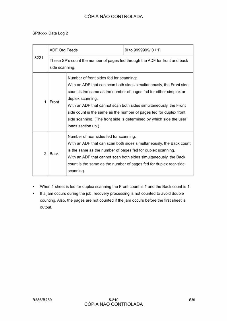
SP8-xxx Data Log 2
B286/B289 5-210 SM
ADF Org Feeds [0 to 9999999/ 0 / 1]
8221 These SP�s count the number of pages fed through the ADF for front and back
side scanning.
1 Front
Number of front sides fed for scanning:
With an ADF that can scan both sides simultaneously, the Front side
count is the same as the number of pages fed for either simplex or
duplex scanning.
With an ADF that cannot scan both sides simultaneously, the Front
side count is the same as the number of pages fed for duplex front
side scanning. (The front side is determined by which side the user
loads section up.)
2 Back
Number of rear sides fed for scanning:
With an ADF that can scan both sides simultaneously, the Back count
is the same as the number of pages fed for duplex scanning.
With an ADF that cannot scan both sides simultaneously, the Back
count is the same as the number of pages fed for duplex rear-side
scanning.
! When 1 sheet is fed for duplex scanning the Front count is 1 and the Back count is 1.
! If a jam occurs during the job, recovery processing is not counted to avoid double
counting. Also, the pages are not counted if the jam occurs before the first sheet is
output.
CÓPIA NÃO CONTROLADA
CÓPIA NÃO CONTROLADA
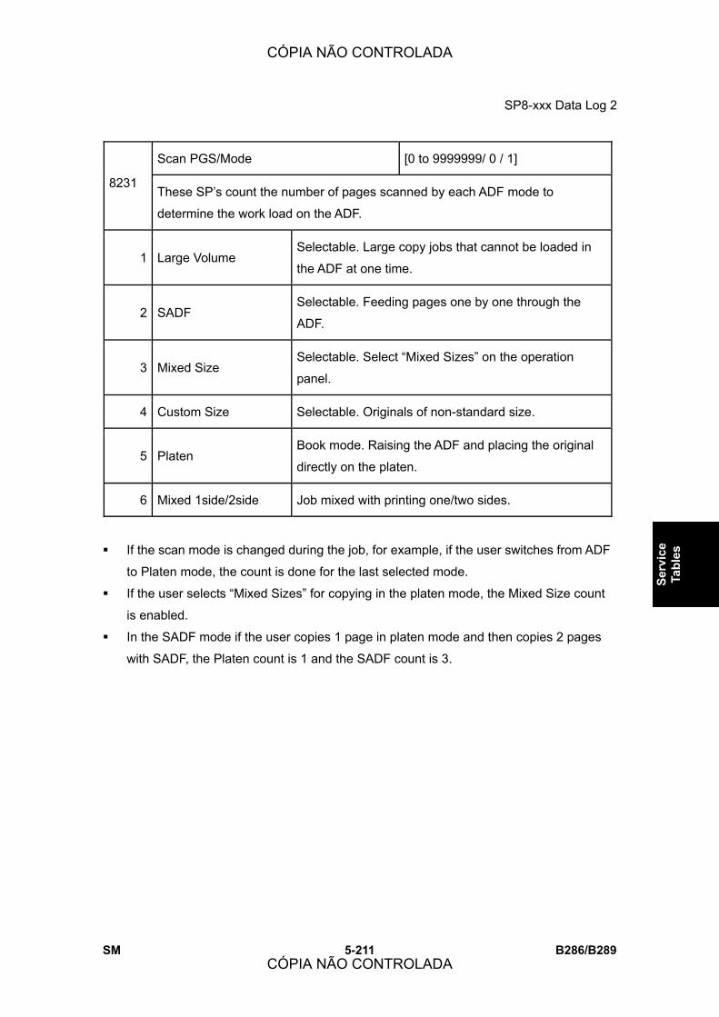
SP8-xxx Data Log 2
SM 5-211 B286/B289
Serv
ice
Tabl
es
Scan PGS/Mode [0 to 9999999/ 0 / 1]
8231 These SP�s count the number of pages scanned by each ADF mode to
determine the work load on the ADF.
1 Large Volume Selectable. Large copy jobs that cannot be loaded in
the ADF at one time.
2 SADF Selectable. Feeding pages one by one through the
ADF.
3 Mixed Size Selectable. Select �Mixed Sizes� on the operation
panel.
4 Custom Size Selectable. Originals of non-standard size.
5 Platen Book mode. Raising the ADF and placing the original
directly on the platen.
6 Mixed 1side/2side Job mixed with printing one/two sides.
! If the scan mode is changed during the job, for example, if the user switches from ADF
to Platen mode, the count is done for the last selected mode.
! If the user selects �Mixed Sizes� for copying in the platen mode, the Mixed Size count
is enabled.
! In the SADF mode if the user copies 1 page in platen mode and then copies 2 pages
with SADF, the Platen count is 1 and the SADF count is 3.
CÓPIA NÃO CONTROLADA
CÓPIA NÃO CONTROLADA

SP8-xxx Data Log 2
B286/B289 5-212 SM
T:Scan PGS/Org [0 to 9999999/ 0 / 1]
8241 These SP�s count the total number of scanned pages by original type for all
jobs, regardless of which application was used.
C:Scan PGS/Org [0 to 9999999/ 0 / 1]
8242 These SP�s count the number of pages scanned by original type for Copy
jobs.
S:Scan PGS/Org [0 to 9999999/ 0 / 1]
8245 These SP�s count the number of pages scanned by original type for Scan
jobs.
L:Scan PGS/Org [0 to 9999999/ 0 / 1]
8246 These SP�s count the number of pages scanned and stored from within the
document server mode screen at the operation panel, and with the Store File
button from within the Copy mode screen
8241 8242 8245 8246
824x 1: Text Yes Yes Yes Yes
824x 2: Text/Photo Yes Yes Yes Yes
824x 3: Photo Yes Yes Yes Yes
824x 4: GenCopy, Pale Yes Yes Yes Yes
824x 5: Map Yes Yes Yes Yes
824x 11: Other Yes Yes Yes Yes
! If the scan mode is changed during the job, for example, if the user switches from ADF
to Platen mode, the count is done for the last selected mode.
CÓPIA NÃO CONTROLADA
CÓPIA NÃO CONTROLADA

SP8-xxx Data Log 2
SM 5-213 B286/B289
Serv
ice
Tabl
es
8251 T:Scan PGS/ImgEdt
8252 C:Scan PGS/ImgEdt
8254 P:Scan PGS/ImgEdt
8256 L:Scan PGS/ImgEdt
8257 O:Scan PGS/ImgEdt
These SP�s show how many times Image Edit
features have been selected at the operation panel
for each application. Some examples of these
editing features are:
Erase> Border
Erase> Center
Image Repeat
Centering
Positive/Negative
[0 to 9999999/ 0 / 1]
Note: The count totals the number of times the edit
features have been used. A detailed breakdown of
exactly which features have been used is not given.
! The L: counter counts the number of pages stored from within the document server
mode screen at the operation panel, and with the Store File button from within the
Copy mode screen.
8281 T:Scan PGS/TWAIN
8285 S:Scan PGS/TWAIN
These SP�s count the number of pages scanned
using a TWAIN driver. These counters reveal
how the TWAIN driver is used for delivery
functions.
[0 to 9999999/ 0 / 1]
Note: At the present time, these counters
perform identical counts.
8291 T:Scan PGS/Stamp
8295 S:Scan PGS/Stamp
These SP�s count the number of pages stamped
with the stamp in the ADF unit.
[0 to 9999999/ 0 / 1]
CÓPIA NÃO CONTROLADA
CÓPIA NÃO CONTROLADA
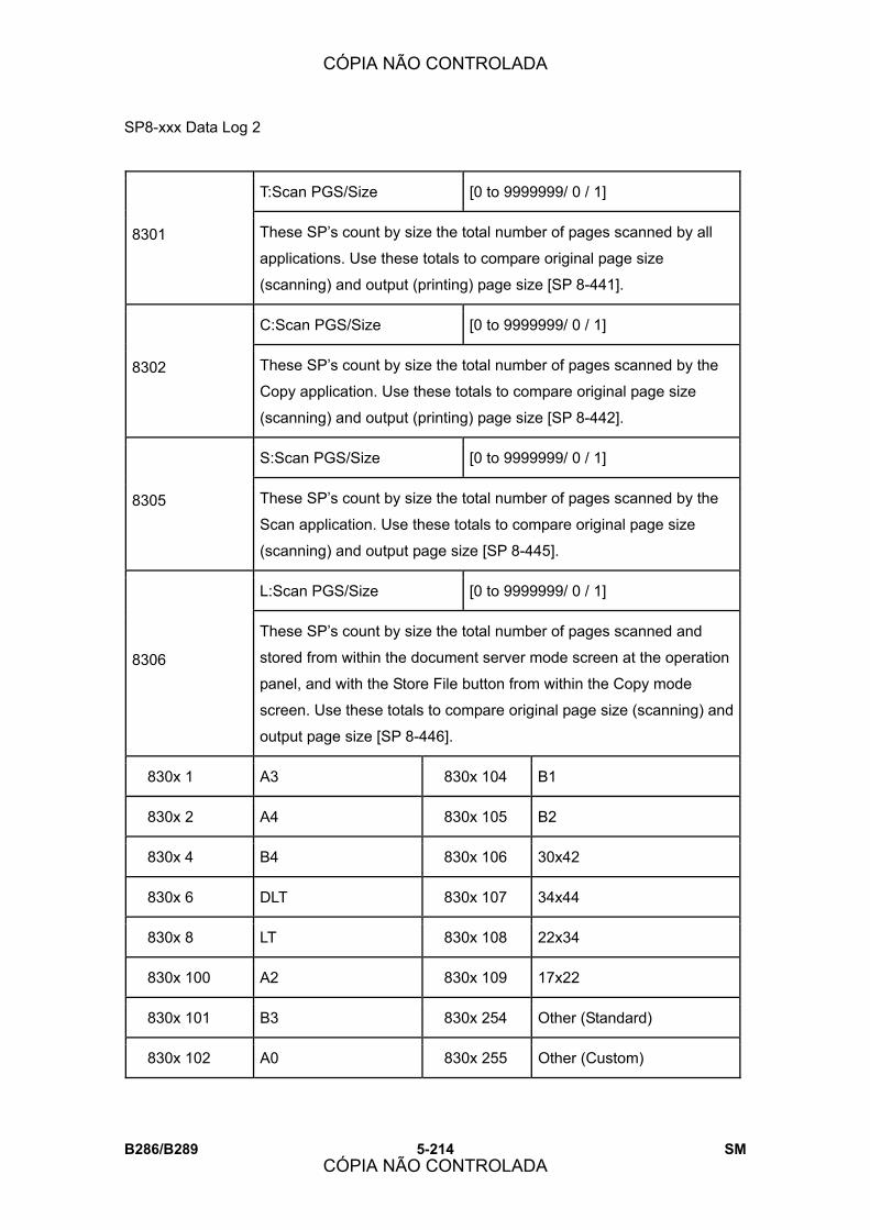
SP8-xxx Data Log 2
B286/B289 5-214 SM
T:Scan PGS/Size [0 to 9999999/ 0 / 1]
8301 These SP�s count by size the total number of pages scanned by all
applications. Use these totals to compare original page size
(scanning) and output (printing) page size [SP 8-441].
C:Scan PGS/Size [0 to 9999999/ 0 / 1]
8302 These SP�s count by size the total number of pages scanned by the
Copy application. Use these totals to compare original page size
(scanning) and output (printing) page size [SP 8-442].
S:Scan PGS/Size [0 to 9999999/ 0 / 1]
8305 These SP�s count by size the total number of pages scanned by the
Scan application. Use these totals to compare original page size
(scanning) and output page size [SP 8-445].
L:Scan PGS/Size [0 to 9999999/ 0 / 1]
8306
These SP�s count by size the total number of pages scanned and
stored from within the document server mode screen at the operation
panel, and with the Store File button from within the Copy mode
screen. Use these totals to compare original page size (scanning) and
output page size [SP 8-446].
830x 1 A3 830x 104 B1
830x 2 A4 830x 105 B2
830x 4 B4 830x 106 30x42
830x 6 DLT 830x 107 34x44
830x 8 LT 830x 108 22x34
830x 100 A2 830x 109 17x22
830x 101 B3 830x 254 Other (Standard)
830x 102 A0 830x 255 Other (Custom)
CÓPIA NÃO CONTROLADA
CÓPIA NÃO CONTROLADA

SP8-xxx Data Log 2
SM 5-215 B286/B289
Serv
ice
Tabl
es
830x 103 A1
T:Scan PGS/Rez [0 to 9999999/ 0 / 1]
8311 These SP�s count by resolution setting the total number of pages scanned
by applications that can specify resolution settings.
S:Scan PGS/Rez [0 to 9999999/ 0 / 1]
8315 These SP�s count by resolution setting the total number of pages scanned
by applications that can specify resolution settings.
Note: At the present time, 8311 and 8315 perform identical counts.
831x 1 1200dpi ~
831x 2 600dpi ~ 1199dpi
831x 3 400dpi ~ 599dpi
831x 4 200dpi ~ 399dpi
831x 5 ~ 199dpi
! Copy resolution settings are fixed so they are not counted.
! The Fax application does not allow finely-adjusted resolution settings so no count is
done for the Fax application.
CÓPIA NÃO CONTROLADA
CÓPIA NÃO CONTROLADA

SP8-xxx Data Log 2
B286/B289 5-216 SM
8381 T:Total PrtPGS
8382 C:Total PrtPGS
8384 P:Total PrtPGS
8385 S:Total PrtPGS
8386 L:Total PrtPGS
8387 O:Total PrtPGS
These SP�s count the number of pages printed by
the operator. The counter for the application used
for storing the pages increments.
[0 to 99 999 999/ 0 / 1]
The L: counter counts the number of pages stored
from within the document server mode screen at
the operation panel. Pages stored with the Store
File button from within the Copy mode screen go to
the C: counter.
838x 1 Field Number Total number of copies (regardless of size)
838x 2 Length (High) Total length
838x 3 Length (Low) Total length
838x 4 Area (High) Total area coverage
838x 5 Area (Low) Total area coverage
Note:
! The values for �Length� are displayed in mm. If a �Length� reading is
�42126� this is 42,126 mm (42.126 m).
! The values for �Area� are displayed as mm2. If an �Area� reading is
�33213257� this is 33,213,257 mm2 (33,213.257 m2).
! The counts for the �Length� and �Area� start with �Low.� Once the
count exceeds the width of the field on the display the �Low� field will
reset to �0� and the count overflows to the �High� SP codes. (This is
necessary because the fields of the �Low� SP codes are limited to 8
digits and not wide enough to display the full reading for a reading
larger than 8 digits.)
! Always check the �Low� SP first. If the �Low� display is zero, check the
�High� field.
! When the length count reaches �99,999,999� in the �Low� field (8
digits), for example, after the next copy the count will show �1� in the
�High� field and �00 000 000� in the �Low.� Multiply the �1� in the �High�
field by: 1) 108� (100,000,000 mm), 2) 105 (100, 000 m) or 3) 102 (100
kilometers) to determine the accurate count.
CÓPIA NÃO CONTROLADA
CÓPIA NÃO CONTROLADA

SP8-xxx Data Log 2
SM 5-217 B286/B289
Serv
ice
Tabl
es
! When several documents are merged for a print job, the number of pages stored are
counted for the application that stored them.
! These counters are used primarily to calculate charges on use of the machine, so the
following pages are not counted as printed pages:
! Blank pages in a duplex printing job.
! Blank pages inserted as document covers, chapter title sheets, and slip sheets.
! Reports printed to confirm counts.
! All reports done in the service mode (service summaries, engine maintenance reports,
etc.)
! Test prints for machine image adjustment.
! Error notification reports.
! Partially printed pages as the result of a jam.
8401 T:PrtPGS/LS
8402 C:PrtPGS/LS
8404 P:PrtPGS/LS
8405 S:PrtPGS/LS
8406 L:PrtPGS/LS
These SP�s count the number of pages printed from the
document server. The counter for the application used to
print the pages is incremented.
The L: counter counts the number of jobs stored from
within the document server mode screen at the operation
panel.
[0 to 9999999/ 0 / 1]
! Print jobs done with Web Image Monitor and Desktop Binder are added to the L: count.
! Fax jobs done with Web Image Monitor and Desktop Binder are added to the F: count.
8411 Prints/Duplex
This SP counts the amount of paper (front/back counted as
1 page) used for duplex printing. Last pages printed only on
one side are not counted.
[0 to 9999999/ 0 / 1]
CÓPIA NÃO CONTROLADA
CÓPIA NÃO CONTROLADA

SP8-xxx Data Log 2
B286/B289 5-218 SM
T:PrtPGS/Dup Comb [0 to 9999999/ 0 / 1]
8421 These SP�s count by binding and combine, and n-Up settings the number
of pages processed for printing. This is the total for all applications.
C:PrtPGS/Dup Comb [0 to 9999999/ 0 / 1]
8422 These SP�s count by binding and combine, and n-Up settings the number
of pages processed for printing by the application.
P:PrtPGS/Dup Comb [0 to 9999999/ 0 / 1]
8424 These SP�s count by binding and combine, and n-Up settings the number
of pages processed for printing by the printer application.
S:PrtPGS/Dup Comb [0 to 9999999/ 0 / 1]
8425 These SP�s count by binding and combine, and n-Up settings the number
of pages processed for printing by the scanner application.
L:PrtPGS/Dup Comb [0 to 9999999/ 0 / 1]
8426 These SP�s count by binding and combine, and n-Up settings the number
of pages processed for printing from within the document server mode
window at the operation panel.
O:PrtPGS/Dup Comb [0 to 9999999/ 0 / 1]
8427 These SP�s count by binding and combine, and n-Up settings the number
of pages processed for printing by Other applications
842x 1 Simplex> Duplex
842x 2 Duplex> Duplex
842x 3 Book> Duplex
842x 4 Simplex Combine
842x 5 Duplex Combine
842x 6 2> 2 pages on 1 side (2-Up)
CÓPIA NÃO CONTROLADA
CÓPIA NÃO CONTROLADA

SP8-xxx Data Log 2
SM 5-219 B286/B289
Serv
ice
Tabl
es
842x 7 4> 4 pages on 1 side (4-Up)
842x 8 6> 6 pages on 1 side (6-Up)
842x 9 8> 8pages on 1 side (8-Up)
842x 10 9> 9 pages on 1 side (9-Up)
842x 11 16> 16 pages on 1 side (16-Up)
842x 12 Booklet
842x 13 Magazine
! These counts (SP8421 to SP8427) are especially useful for operators who need to
improve their compliance with ISO standards for the reduction of paper consumption.
! Pages that are only partially printed with the n-Up functions are counted as 1 page.
! Here is a summary of how the counters work for Booklet and Magazine modes:
Booklet Magazine
Original Pages Count Original Pages Count
1 1 1 1
2 2 2 2
3 2 3 2
4 2 4 2
5 3 5 4
6 4 6 4
7 4 7 4
8 4 8 4
CÓPIA NÃO CONTROLADA
CÓPIA NÃO CONTROLADA
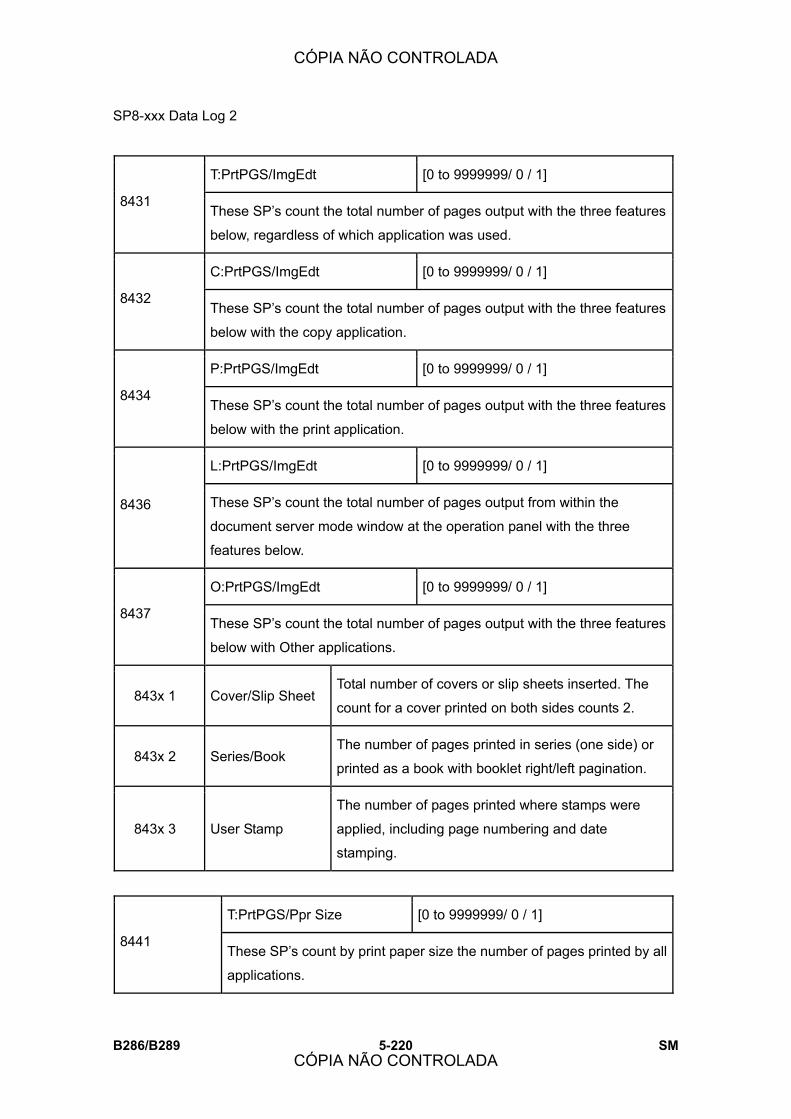
SP8-xxx Data Log 2
B286/B289 5-220 SM
T:PrtPGS/ImgEdt [0 to 9999999/ 0 / 1]
8431 These SP�s count the total number of pages output with the three features
below, regardless of which application was used.
C:PrtPGS/ImgEdt [0 to 9999999/ 0 / 1]
8432 These SP�s count the total number of pages output with the three features
below with the copy application.
P:PrtPGS/ImgEdt [0 to 9999999/ 0 / 1]
8434 These SP�s count the total number of pages output with the three features
below with the print application.
L:PrtPGS/ImgEdt [0 to 9999999/ 0 / 1]
8436 These SP�s count the total number of pages output from within the
document server mode window at the operation panel with the three
features below.
O:PrtPGS/ImgEdt [0 to 9999999/ 0 / 1]
8437 These SP�s count the total number of pages output with the three features
below with Other applications.
843x 1 Cover/Slip Sheet Total number of covers or slip sheets inserted. The
count for a cover printed on both sides counts 2.
843x 2 Series/Book The number of pages printed in series (one side) or
printed as a book with booklet right/left pagination.
843x 3 User Stamp
The number of pages printed where stamps were
applied, including page numbering and date
stamping.
T:PrtPGS/Ppr Size [0 to 9999999/ 0 / 1]
8441 These SP�s count by print paper size the number of pages printed by all
applications.
CÓPIA NÃO CONTROLADA
CÓPIA NÃO CONTROLADA

SP8-xxx Data Log 2
SM 5-221 B286/B289
Serv
ice
Tabl
es
C:PrtPGS/Ppr Size [0 to 9999999/ 0 / 1]
8442 These SP�s count by print paper size the number of pages printed by
the copy application.
P:PrtPGS/Ppr Size [0 to 9999999/ 0 / 1]
8444 These SP�s count by print paper size the number of pages printed by
the printer application.
S:PrtPGS/Ppr Size [0 to 9999999/ 0 / 1]
8445 These SP�s count by print paper size the number of pages printed by
the scanner application.
L:PrtPGS/Ppr Size [0 to 9999999/ 0 / 1]
8446 These SP�s count by print paper size the number of pages printed from
within the document server mode window at the operation panel.
O:PrtPGS/Ppr Size [0 to 9999999/ 0 / 1]
8447 These SP�s count by print paper size the number of pages printed by
Other applications.
844x 1 A3 844x 240 841 mm Custom:-A0
844x 2 A4 844x 241 594 mm Custom
844x 4 B4 844x 242 420 mm Custom
844x 6 DLT 844x 243 297 mm Custom
844x 8 LT 844x 244 210 mm Custom
844x 100 A2 844x 245 728 mm Custom
844x 101 B3 844x 246 515 mm Custom
844x 102 A0 844x 247 364 mm Custom
844x 103 A1 844x 248 257 mm Custom
844x 104 B1 844x 249 30/34/36 inch Custom
CÓPIA NÃO CONTROLADA
CÓPIA NÃO CONTROLADA
SP8-xxx Data Log 2
B286/B289 5-222 SM
844x 105 B2 844x 250 22 inch Custom
844x 106 30x42 844x 251 17 inch Custom
844x 107 34x44 844x 252 11 inch Custom
844x 108 22x34 844x 253 8.5 inch Custom
844x 109 17x22 844x 254 Other (Standard)
844x 239 841 mm Custom: A0- 844x 255 Other (Custom)
! These counters do not distinguish between LEF and SEF.
PrtPGS/Ppr Tray [0 to 9999999/ 0 / 1] 8451
These SP�s count the number of sheets fed from each paper feed station.
1 Bypass Bypass Table
2 Tray 1 Copier
3 Tray 2 Copier
4 Tray 3 Paper Tray Unit (Option)
5 Tray 4 Paper Tray Unit (Option)
6 Tray 5 LCT (Option)
7 Tray 6
8 Tray 7
9 Tray 8
10 Tray 9
Currently not used.
CÓPIA NÃO CONTROLADA
CÓPIA NÃO CONTROLADA
SP8-xxx Data Log 2
SM 5-223 B286/B289
Serv
ice
Tabl
es
T:PrtPGS/Ppr Type [0 to 9999999/ 0 / 1]
8461
These SP�s count by paper type the number pages printed by all
applications.
These counters are not the same as the PM counter. The PM counter is
based on feed timing to accurately measure the service life of the feed
rollers. However, these counts are based on output timing.
Blank sheets (covers, chapter covers, slip sheets) are also counted.
During duplex printing, pages printed on both sides count as 1, and a page
printed on one side counts as 1.
C:PrtPGS/Ppr Type [0 to 9999999/ 0 / 1]
8462 These SP�s count by paper type the number pages printed by the copy
application.
P:PrtPGS/Ppr Type [0 to 9999999/ 0 / 1]
8464 These SP�s count by paper type the number pages printed by the printer
application.
L:PrtPGS/Ppr Type [0 to 9999999/ 0 / 1]
8466 These SP�s count by paper type the number pages printed from within the
document server mode window at the operation panel.
846x 1 Normal
846x 2 Recycled
846x 3 Special
846x 4 Thick
846x 5 Normal (Back)
846x 6 Thick (Back)
846x 7 OHP
846x 8 Other
CÓPIA NÃO CONTROLADA
CÓPIA NÃO CONTROLADA

SP8-xxx Data Log 2
B286/B289 5-224 SM
PrtPGS/Mag [0 to 9999999/ 0 / 1] 8471
These SP�s count by magnification rate the number of pages printed.
1 ~49%
2 50%~99%
3 100%
4 101%~200%
5 201%~
! Counts are done for magnification adjusted for pages, not only on the operation panel
but performed remotely with an external network application capable of performing
magnification adjustment as well.
! Magnification adjustments done with printer drivers with PC applications such as Excel
are also counted.
! Magnification adjustments done for adjustments after they have been stored on the
document server are not counted.
! Magnification adjustments performed automatically during Auto Reduce/Enlarge
copying are counted.
! The magnification rates of blank cover sheets, slip sheets, etc. are automatically
assigned a rate of 100%.
8481 T:PrtPGS/ TonSave
8484 P:PrtPGS/TonSave
These SP�s count the number of pages printed with the toner Save feature
switched on.
Note: These SP�s return the same results as this SP is limited to the Print
application.
[0 to 9999999/ 0 / 1]
CÓPIA NÃO CONTROLADA
CÓPIA NÃO CONTROLADA

SP8-xxx Data Log 2
SM 5-225 B286/B289
Serv
ice
Tabl
es
T:PrtPGS/Emul [0 to 9999999/ 0 / 1]
8511 These SP�s count by printer emulation mode the total number of pages
printed.
P:PrtPGS/Emul [0 to 9999999/ 0 / 1]
8514 These SP�s count by printer emulation mode the total number of pages
printed.
851x 1 RPCS
851x 2 RPDL
851x 3 PS3
851x 4 R98
851x 5 R16
851x 6 GL/GL2
851x 7 R55
851x 8 RTIFF
851x 9 PDF
851x 10 PCL5e/5c
851x 11 PCL XL
851x 12 IPDL-C
851x 13 BM-Links Japan Only
851x 14 Other
! SP8511 and SP8514 return the same results as they are both limited to the Print
application.
! Print jobs output to the document server are not counted.
CÓPIA NÃO CONTROLADA
CÓPIA NÃO CONTROLADA

SP8-xxx Data Log 2
B286/B289 5-226 SM
T:PrtPGS/FIN [0 to 9999999/ 0 / 1] 8521
These SP�s count by finishing mode the total number of pages printed by
all applications.
C:PrtPGS/FIN [0 to 9999999/ 0 / 1] 8522
These SP�s count by finishing mode the total number of pages printed by
the Copy application.
P:PrtPGS/FIN [0 to 9999999/ 0 / 1] 8524
These SP�s count by finishing mode the total number of pages printed by
the Print application.
S:PrtPGS/FIN [0 to 9999999/ 0 / 1] 8525
These SP�s count by finishing mode the total number of pages printed by
the Scanner application.
L:PrtPGS/FIN [0 to 9999999/ 0 / 1] 8526
These SP�s count by finishing mode the total number of pages printed from
within the document server mode window at the operation panel.
852x 1 Sort
852x 2 Stack
852x 3 Staple
852x 4 Booklet
852x 5 Z-Fold
852x 6 Punch
852x 7 Other
Note:
! If stapling is selected for finishing and the stack is too large for stapling, the unstapled
pages are still counted.
! The counts for staple finishing are based on output to the staple tray, so jam
recoveries are counted.
CÓPIA NÃO CONTROLADA
CÓPIA NÃO CONTROLADA

SP8-xxx Data Log 2
SM 5-227 B286/B289
Serv
ice
Tabl
es
8531 Staples This SP counts the amount of staples used by the machine.
[0 to 9999999/ 0 / 1]
T:Counter [0 to 9999999/ 0 / 1]
8581
These SP�s count the total output broken down by color output, regardless
of the application used. In addition to being displayed in the SMC Report,
these counters are also displayed in the User tools display on the copy
machine.
Note: This SP is expanded for color MFP and color LP machines. For this
machine, the count is done for black only.
O:Counter [0 to 9999999/ 0 / 1]
8591 These SP�s count the totals for A3/DLT paper use, number of duplex pages
printed, and the number of staples used. These totals are for Other (O:)
applications only.
CÓPIA NÃO CONTROLADA
CÓPIA NÃO CONTROLADA
SP8-xxx Data Log 2
B286/B289 5-228 SM
T:S-to-Email PGS [0 to 9999999/ 0 / 1]
8651 These SP�s count by color mode the total number of pages attached to an
e-mail for both the Scan and document server applications.
Note: This SP is expanded for color MFP and color LP machines. For this
machine, the count is done for black only.
S:S-to-Email PGS [0 to 9999999/ 0 / 1]
8655 These SP�s count by color mode the total number of pages attached to an
e-mail for the Scan application only.
Note: This SP is expanded for color MFP and color LP machines. For this
machine, the count is done for black only.
! The count for B/W pages is done after the document is stored on the HDD. If the job is
cancelled before it is stored, the pages are not counted.
! If Scan- to -Email is used to send a 10-page document to 5 addresses, the count is 10
(the pages are sent to the same SMTP server together).
! If Scan- to -PC is used to send a 10-page document to 5 folders, the count is 50 (the
document is sent to each destination of the SMB/FTP server).
! Due to restrictions on some devices, if Scan- to -Email is used to send a 10-page
document to a large number of destinations, the count may be divided and counted
separately. For example, if a 10-page document is sent to 200 addresses, the count is
10 for the first 100 destinations and the count is also 10 for the second 100
destinations, for a total of 20.).
CÓPIA NÃO CONTROLADA
CÓPIA NÃO CONTROLADA

SP8-xxx Data Log 2
SM 5-229 B286/B289
Serv
ice
Tabl
es
T:Deliv PGS/PC [0 to 9999999/ 0 / 1]
8671 These SP�s count by color mode the total number of pages sent to a folder
on a PC (Scan- to -PC) with the Scan and LS applications.
Note: This SP is expanded for color MFP and color LP machines. For this
machine, the count is done for black only.
S:Deliv PGS/PC [0 to 9999999/ 0 / 1]
8675 These SP�s count by color mode the total number of pages sent with Scan-
to -PC with the Scan application.
Note: This SP is expanded for color MFP and color LP machines. For this
machine, the count is done for black only.
8691 T:TX PGS/LS
8692 C:TX PGS/LS
8694 P:TX PGS/LS
8695 S:TX PGS/LS
8696 L:TX PGS/LS
These SP�s count the number of pages sent from the
document server. The counter for the application that
was used to store the pages is incremented.
[0 to 9999999/ 0 / 1]
The L: counter counts the number of pages stored
from within the document server mode screen at the
operation panel.
! Print jobs done with Web Image Monitor and Desk TopBinder are added to the count.
! If several documents are merged for sending, the number of pages s to red are
counted for the application that stored them.
! When several documents are sent by a Fax broadcast, the F: count is done for the
number of pages sent to each destination.
CÓPIA NÃO CONTROLADA
CÓPIA NÃO CONTROLADA

SP8-xxx Data Log 2
B286/B289 5-230 SM
TX PGS/Port [0 to 9999999/ 0 / 1]
8701 These SP�s count the number of pages sent by the physical port used to
send them. For example, if a 3-page original is sent to 4 destinations via
ISDN G4, the count for ISDN (G3, G4) is 12.
1 PSTN-1
2 PSTN-2
3 PSTN-3
4 ISDN (G3,G4)
5 Network
T:Scan PGS/Comp [0 to 9999999/ 1]
8 711 These SP�s count the number of compressed pages scanned in to the
document server, counted by the formats listed below.
1 JPEG/JPEG2000
2 TIFF (Multi/Single)
3 PDF
4 Other
5 PDF Comp
CÓPIA NÃO CONTROLADA
CÓPIA NÃO CONTROLADA
SP8-xxx Data Log 2
SM 5-231 B286/B289
Serv
ice
Tabl
es
S:Scan PGS/Comp
8715 These SP�s count the number of compressed pages scanned by the scan
application, counted by the formats listed below.
1 JPEG/JPEG2000 [0 to 9999999/ 1]
2 TIFF (Multi/Single)
3 PDF
4 Other
5 PDF Comp
RX PGS/Port
8741 These SP�s count the number of pages received by the physical port used to
receive them.
[0 to 9999999/ 0 / 1]
1 PSTN-1
2 PSTN-2
3 PSTN-3
4 ISDN (G3,G4)
5 Network
Dev Counter
8771
These SP�s count the frequency of use (number of rotations of the
development rollers) for black and other color toners.
Note: For machines that do not support color, the Black toner count is the
same as the total count.
[0 to 9999999/ 0 / 1]
CÓPIA NÃO CONTROLADA
CÓPIA NÃO CONTROLADA

SP8-xxx Data Log 2
B286/B289 5-232 SM
Pixel Coverage Ratio
8781 This SP displays the number of toner bottles used. The count is done based
on the equivalent of 1,000 pages per bottle.
8791 LS Memory Remain
This SP displays the percent of space available on the document server
for storing documents.
[0 to 100/ 0 / 1]
Toner Remain
8801
This SP displays the percent of toner remaining for each color. This SP
allows the user to check the toner supply at any time.
Note: This method of measuring remaining toner supply (1% steps) is
more precise better than other machines in the market that can only
measure increments of 10 (10% steps).
[0 to 100/ 0 / 1]
Cover Cnt: 0-10%
8851 These SP�s count the percentage of toner dot coverage.
[0 to 9999999]
11 0~2%
21 3~4%
31 5~7%
41 8~10%
CÓPIA NÃO CONTROLADA
CÓPIA NÃO CONTROLADA

SP8-xxx Data Log 2
SM 5-233 B286/B289
Serv
ice
Tabl
es
Cvr Cnt: 11-20%
8861 This SP counts the number of copies in the toner dot coverage range
11-20%
[0 to 9999999]
Cvr Cnt: 21-30%
8871 This SP counts the number of copies in the toner dot coverage range
21-30%
[0 to 9999999]
Cvr Cnt: 31%~
8881 This SP counts the number of copies in the toner dot coverage range 31%
and over.
[0 to 9999999]
8891 Page/Toner Bottle Previous cartridge
8901 Page/Toner_Prev1 Previous but 1
8911 Page/Toner_Prev2 Previous but 2
Counts that record number
of pages per toner cartridge.
Cvr Cnt Total
8921 These SP�s display the percent and number of pages for black toner
coverage.
1 Coverage (%): BK
11 Coverage (/P):BK
CÓPIA NÃO CONTROLADA
CÓPIA NÃO CONTROLADA

SP8-xxx Data Log 2
B286/B289 5-234 SM
Machine Status
8941 These SP�s count the amount of time the machine spends in each operation
mode. These SP�s are useful for operators who need to investigate machine
operation for improvement in their compliance with ISO Standards.
[0 to 9999999/ 0 / 1]
1 Operation Time
Engine operation time. Does not include time while
controller is saving data to HDD (while engine is not
operating).
2 Standby Time
Engine not operating. Includes time while controller
saves data to HDD. Does not include time spent in
Energy Save, Low Power, or Off modes.
3 Energy Save Time Includes time while the machine is performing
background printing.
4 Low Power Time
Includes time in Energy Save mode with Engine on.
Includes time while machine is performing
background printing.
5 Off Mode Time
Includes time while machine is performing
background printing. Does not include time machine
remains powered off with the power switches.
6 SC Total down time due to SC errors.
7 PrtJam Total down time due to paper jams during printing.
8 OrgJam Total down time due to original jams during
scanning.
9 Supply PM Unit End Total down time due to toner end.
CÓPIA NÃO CONTROLADA
CÓPIA NÃO CONTROLADA
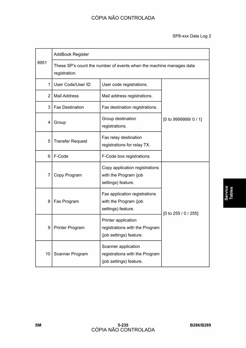
SP8-xxx Data Log 2
SM 5-235 B286/B289
Serv
ice
Tabl
es
AddBook Register
8951 These SP�s count the number of events when the machine manages data
registration.
1 User Code/User ID User code registrations.
2 Mail Address Mail address registrations.
3 Fax Destination Fax destination registrations.
4 Group Group destination
registrations.
5 Transfer Request Fax relay destination
registrations for relay TX.
6 F-Code F-Code box registrations.
[0 to 9999999/ 0 / 1]
7 Copy Program
Copy application registrations
with the Program (job
settings) feature.
8 Fax Program
Fax application registrations
with the Program (job
settings) feature.
9 Printer Program
Printer application
registrations with the Program
(job settings) feature.
10 Scanner Program
Scanner application
registrations with the Program
(job settings) feature.
[0 to 255 / 0 / 255]
CÓPIA NÃO CONTROLADA
CÓPIA NÃO CONTROLADA

SP8-xxx Data Log 2
B286/B289 5-236 SM
Admin. Counter List
8999 This SP provides a central point for display of important information for the
system administrator.
1 Total Print total (copies and prints)
3 Copy: BW Copy totals (not print jobs)
7 Printer: BW Print totals (not copy jobs)
15 Coverage: BW(%) Total coverage (copies/prints)
17 Coverage: BW Print Page (%) Total coverage (print jobs only)
102 Transmission Total: BW Jobs sent to document server,
scan-to-email.
105 Scanner Transmission: BW Jobs scanned to document server,
scan-to-email.
CÓPIA NÃO CONTROLADA
CÓPIA NÃO CONTROLADA

DETAILS
CÓPIA NÃO CONTROLADA
CÓPIA NÃO CONTROLADA

CÓPIA NÃO CONTROLADA
CÓPIA NÃO CONTROLADA

Overview
SM 6-1 B286/B289
Det
ails
6. DETAILS
6.1 OVERVIEW
6.1.1 MACHINE GENERAL LAYOUT
1. Image Writing Unit Uses an LPH (LED Print Head)
2. Scanner Unit Uses a CIS (Contact Image Sensor) unit for scanning. The
CIS is made of 5 sensor arrays connected at four joints.
CÓPIA NÃO CONTROLADA
CÓPIA NÃO CONTROLADA

Overview
B286/B289 6-2 SM
The CIS scans the face-down original from below.
3. Cleaning Unit A counter blade cleans the drum.
4. Fusing Unit
The hot roller contains one halogen lamp. The machine
uses the applicable fusing temperature for the paper size
and paper type that the user input at the operation panel.
5. OPC Drum
The components around the OPC drum do the charging,
image writing, development, transfer, separation, cleaning,
and quenching.
6. Manual Feed Table The user can feed paper from the manual feed table (this
is also referred to as the bypass tray).
7. Roll Feeder Paper also feeds from the optional roll feeder with one or
two paper rolls installed.
8. Paper Cassette Cut sheets are also supplied from the optional paper
cassette.
9. Development Unit Toner transfers from a magnetic roller to the OPC drum.
An ID sensor controls the toner concentration.
CÓPIA NÃO CONTROLADA
CÓPIA NÃO CONTROLADA

Overview
SM 6-3 B286/B289
Det
ails
6.1.2 MECHANICAL COMPONENT LAYOUT
CÓPIA NÃO CONTROLADA
CÓPIA NÃO CONTROLADA

Overview
B286/B289 6-4 SM
1. Original Table 16. T&S Corona Unit
2. Original Feed Rollers 17. Roll 2 Holders
3. OPC Drum 18. Roll 2 Paper Feed Rollers
4. Charge Corona Unit 19. Lower Output Guide
5. Original Exit Roller 20. Lower Output Stacker
6. Upper Output Stacker 21. Roll 1 Holder
7. Original Upper Exit Guides 22. Paper Cassette
8. Cleaning Unit 23. Paper Cassette Feed Roller
9. Upper Exit Rollers 24. Paper Cassette Grip Rollers
10. Original Exit Guides (Straight-Through) 25. Roll 1 Paper Feed Rollers
11. Paper Exit Junction Gate 26. Cutter
12. Fusing Exit Rollers 27. Roll/Cassette Exit Rollers
13. Fusing Cleaning Roller 28. Registration Rollers
14. Hot Roller 29. Manual Feed Table (Bypass)
15. Pressure Roller
CÓPIA NÃO CONTROLADA
CÓPIA NÃO CONTROLADA
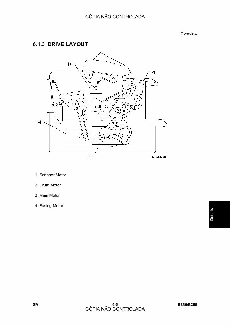
Overview
SM 6-5 B286/B289
Det
ails
6.1.3 DRIVE LAYOUT
1. Scanner Motor
2. Drum Motor
3. Main Motor
4. Fusing Motor
CÓPIA NÃO CONTROLADA
CÓPIA NÃO CONTROLADA

Overview
B286/B289 6-6 SM
6.1.4 ORIGINAL/COPY PAPER PATHS
1. Manual Feed (Bypass) Path
2. Original Path (Upper) Upper output stacker installed.
3. Original Path (Straight-Through) Upper output stacker removed.
4. Paper Path (Upper) Normal (Default)
5. Paper Path (Rear) Selectable *1
6. Paper Path (Paper Cassette)
7. Paper Path (Rolls) B851 (1 Roll), B852 (2 Rolls)
CÓPIA NÃO CONTROLADA
CÓPIA NÃO CONTROLADA
Overview
SM 6-7 B286/B289
Det
ails
*1: The position of the copy-exit selection lever on the rear top edge of the machine
controls where the copy feeds out.
Lever UP Lever DOWN
The operator touches �Upper� or �Lower�
under �Copy Output Location� on the
display to select the exit shown in the
illustration above:
! Upper: Copy feeds out at �2.�
! Lower: Copy feeds out at �4�
�Lower� is selected for the �Copy Output
Location,� so the copy always feeds out at
�4� in the illustration above.
�Upper� cannot be selected. If the operator
selects �Upper,� a message will prompt the
operator that the output destination cannot
be selected.
! For normal operation, the copy exit selection lever must be up, so that the operator
always has the option of selecting either �Upper� or �Lower� for copy exit.
CÓPIA NÃO CONTROLADA
CÓPIA NÃO CONTROLADA

Scanner
B286/B289 6-8 SM
6.2 SCANNER
6.2.1 OVERVIEW
Only one original can be placed face-down on the original table.
Original set sensor [A]: Detects the leading edge of the original. Then the machine stops
original feed for 1 second (Delay 1). This gives the user time to put the paper straight. This
sensor also functions as a width sensor, with the original width sensors (not shown) below
the original feed table.
! Delay 1 can be adjusted. User Tools > System Settings > General Features >
Original Feed Delay 1.
Original feed roller [B]: Feeds the original to the registration sensor [C].
Registration sensor [C]: When this detects the leading edge of the original, the machine
stops original feed for 1 second (Delay 2). This gives the user time to check that the original
is straight. If the original is not straight, the user can push the �Scanner Stop� button to stop
original feed, remove the original, and try again.
! Delay 2 can be adjusted. User Tools > System Settings > General Features >
Original Feed Delay 2.
CIS (Contact Image Sensor) [D]: Scans the original from below.
Original exit sensor [E]: Detects the leading and trailing edge of the original to make sure
that there is no jam.
CÓPIA NÃO CONTROLADA
CÓPIA NÃO CONTROLADA

Scanner
SM 6-9 B286/B289
Det
ails
Original exit rollers [F]: Feed the original out while the scanned image is processed
Upper output tray [G]: Receives the original after scanning. Long originals will curl in the
tray.
! If the original output trays are removed, the original feeds in a straight path, out of
the rear of the machine. The original feed path through the machine is the same.
! The user should remove the original output trays when scanning thick originals so
the original will feed straight out.
Scanner motor [H]: Controls the original feed roller and original exit roller. (See section
6.2.4 �Original Drive Mechanism.�)
6.2.2 SCANNER LAYOUT
[A]: Original Width Sensors. Detect the width of the original.
[B]: Original Set Sensor. Detects when the original is put on the original feed table.
[C]: Original Feed Roller. Feeds the original to the original registration sensor.
[D]: Original Registration Sensor. Detects the leading edge of the original and stops feed
temporarily for the user to align the original manually.
[E]: CIS. Scans the original and sends the image data to the VDB.
[F]: Original Exit Sensor. Detects the leading and trailing edge of the original for job timing.
[G]: Original Exit Roller. Feeds the original out of the machine.
CÓPIA NÃO CONTROLADA
CÓPIA NÃO CONTROLADA
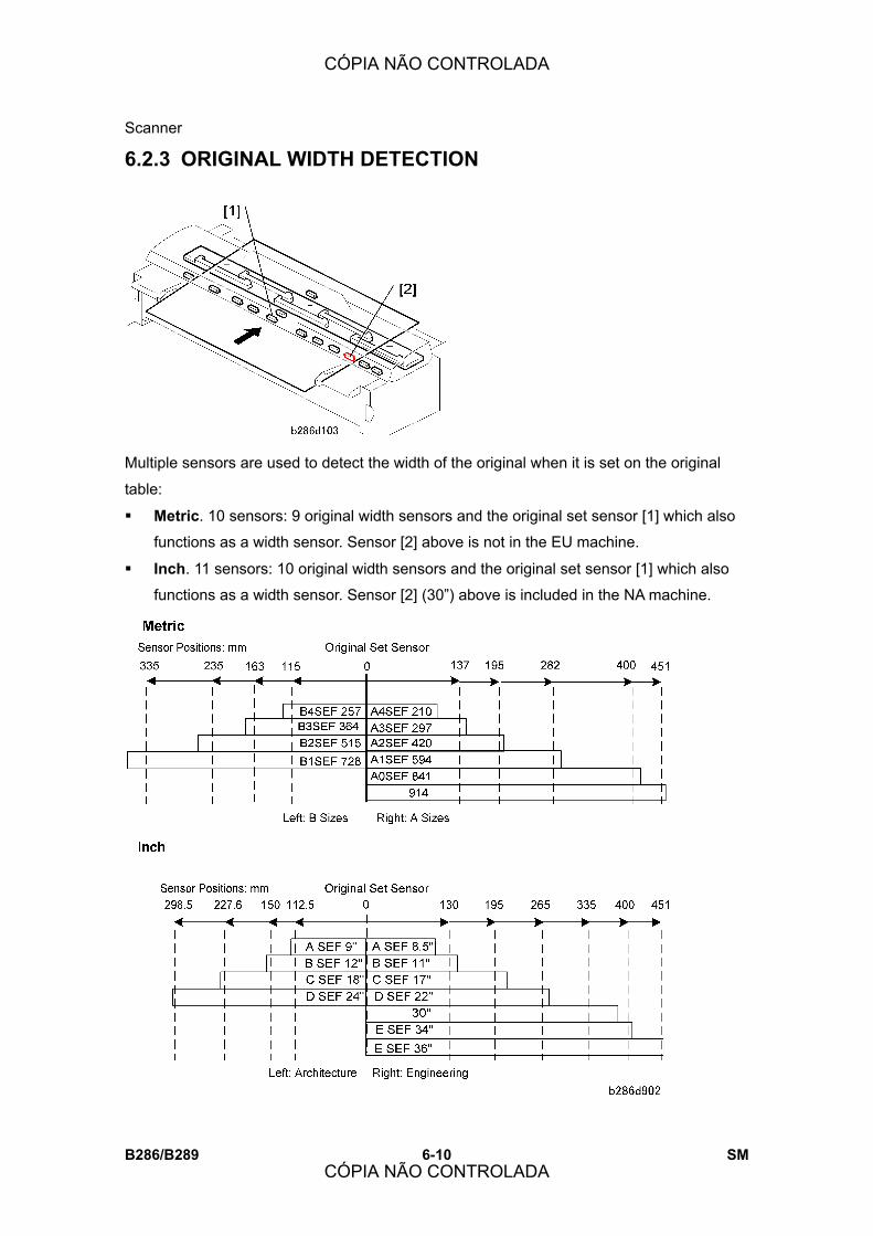
Scanner
B286/B289 6-10 SM
6.2.3 ORIGINAL WIDTH DETECTION
Multiple sensors are used to detect the width of the original when it is set on the original
table:
! Metric. 10 sensors: 9 original width sensors and the original set sensor [1] which also
functions as a width sensor. Sensor [2] above is not in the EU machine.
! Inch. 11 sensors: 10 original width sensors and the original set sensor [1] which also
functions as a width sensor. Sensor [2] (30�) above is included in the NA machine.
CÓPIA NÃO CONTROLADA
CÓPIA NÃO CONTROLADA

Scanner
SM 6-11 B286/B289
Det
ails
The sensors on the left detect B series (Metric) or Architecture (USA) sizes. The sensors
on the right detect A series (Metric) or Engineering (USA) sizes.
The original set sensor detects A4 or 8 ½� �A� size SEF originals. The original width
sensors detect the larger sizes.
6.2.4 ORIGINAL DRIVE MECHANISM
The scanner motor [A] (a stepper motor) and timing belt [B] control the original feed rollers
[C] and original exit rollers [D]. The signal from the original set sensor controls the on/off
timing.
6.2.5 ORIGINAL FEED SPEED
The speed of the original is faster if the magnification ratio is lower.
CÓPIA NÃO CONTROLADA
CÓPIA NÃO CONTROLADA

Scanner
B286/B289 6-12 SM
6.2.6 SCANNING MECHANISM
CIS Structure
This machine uses a contact image sensor [A] (!: Digital Processes � Image Processing
� Black and White CIS Systems).
The scanning unit is below the original feed path. The CIS scans black and white originals
a maximum of 926.5 mm (361/2 inches) wide at 600 dpi.
The CIS unit is made of 5 sections connected at four joints [B]. If you look from above, the
CIS sections are numbered from left to right as CIS-1 to CIS-5.
CÓPIA NÃO CONTROLADA
CÓPIA NÃO CONTROLADA
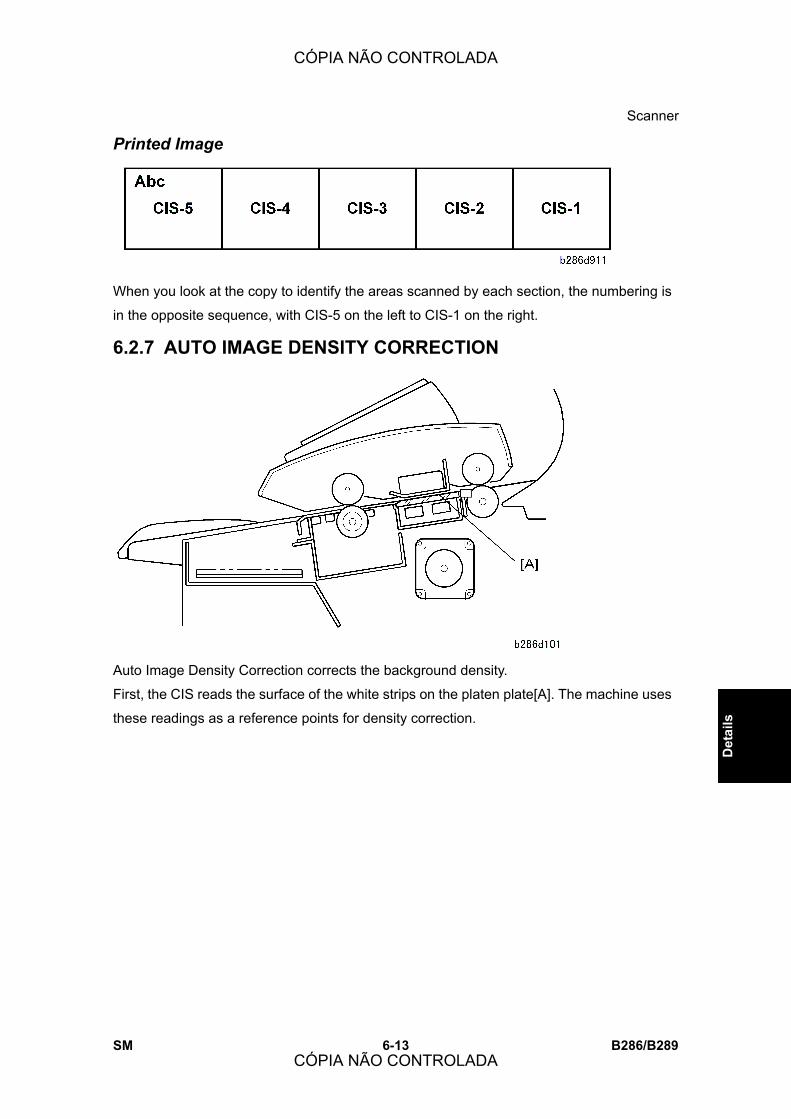
Scanner
SM 6-13 B286/B289
Det
ails
Printed Image
When you look at the copy to identify the areas scanned by each section, the numbering is
in the opposite sequence, with CIS-5 on the left to CIS-1 on the right.
6.2.7 AUTO IMAGE DENSITY CORRECTION
Auto Image Density Correction corrects the background density.
First, the CIS reads the surface of the white strips on the platen plate[A]. The machine uses
these readings as a reference points for density correction.
CÓPIA NÃO CONTROLADA
CÓPIA NÃO CONTROLADA
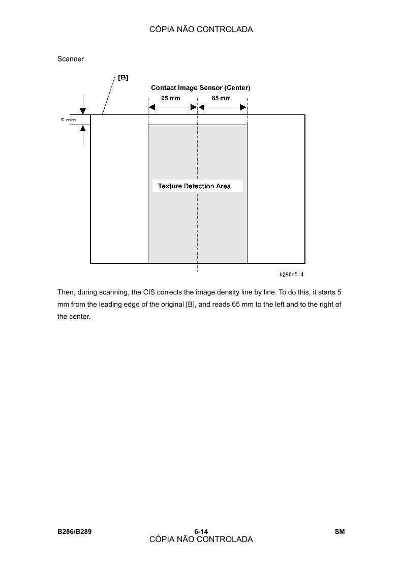
Scanner
B286/B289 6-14 SM
Then, during scanning, the CIS corrects the image density line by line. To do this, it starts 5
mm from the leading edge of the original [B], and reads 65 mm to the left and to the right of
the center.
CÓPIA NÃO CONTROLADA
CÓPIA NÃO CONTROLADA

Image Processing
SM 6-15 B286/B289
Det
ails
6.3 IMAGE PROCESSING
6.3.1 GENERAL IMAGE PROCESSING FLOWCHART
Image processing is done for all seven original image modes on the IPU which handles
data compression and decompression.
CÓPIA NÃO CONTROLADA
CÓPIA NÃO CONTROLADA

Image Processing
B286/B289 6-16 SM
6.3.2 ORIGINAL MODES
Overview Here is a summary of the seven original modes that the operator can select on the
operation panel before scanning the original.
Mode Function
Drawing
Best reproduction of detailed diagrams, specially for drawings with many
thin lines. When Drawing is selected, the auto density feature (ADS) is
automatically switched on.
Note: This selection can be used to sharpen text.
Text
Best reproduction of text and sharp lines. Text mode does not detect
differences between areas of the page that contain text, graphics, or
photographs; all the page is processed as a text original. When this mode is
selected, the auto image density feature (ADS) is automatically switched
on.
Text/Photo
The 2-level error diffusion used in this mode gives the best reproduction for
originals with text and photos on the same page. Grayscales are more
accurate than those achieved with Text mode. When this mode is selected,
the auto image density feature (ADS) is automatically switched on.
Photo
The 2-value dither processing used in this mode removes jagged edges on
photo originals. Gives the best reproduction for copied photographs. When
this mode is selected, the auto image density feature (ADS) is automatically
switched off.
Background
Lines
Ignores blue or green lines in the original. For example, the blue grid
squares of graph paper, or the markings with a dropout blue pencil do not
appear in copies. When this mode is selected, the auto density feature
(ADS) is automatically switched on.
Note: Some blue or green lines may not drop out if they are very thick or of
high density.
Patched
Original
Prevents background from appearing in copies of originals where the
textures of the backgrounds differ. For example, this mode will even out the
backgrounds and eliminate the shadows and lines on page or sheets
CÓPIA NÃO CONTROLADA
CÓPIA NÃO CONTROLADA

Image Processing
SM 6-17 B286/B289
Det
ails
Mode Function
pasted up for design layout. When this mode is selected, the auto image
density feature (ADS) is automatically switched off.
Generation
Copy
Almost the same as the Text mode, but tries to decrease the thickness of
thick characters, repair thin or broken lines of originals, ignore the
background, and erase independent dots that are frequently in copies of
originals which are 2nd, 3rd, etc. generation copies themselves. When this
mode is selected, the auto image density feature (ADS) is automatically
switched off.
Drawing Mode
CÓPIA NÃO CONTROLADA
CÓPIA NÃO CONTROLADA

Image Processing
B286/B289 6-18 SM
Text Mode
CÓPIA NÃO CONTROLADA
CÓPIA NÃO CONTROLADA
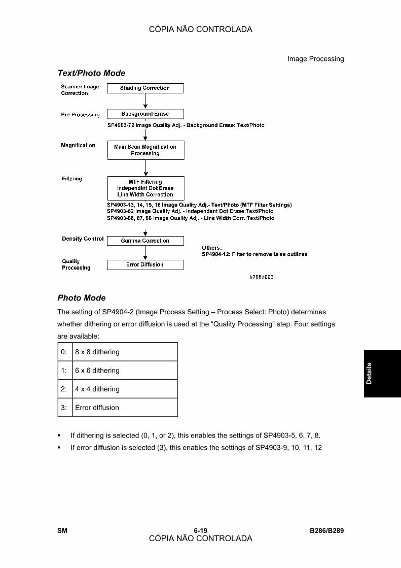
Image Processing
SM 6-19 B286/B289
Det
ails
Text/Photo Mode
Photo Mode The setting of SP4904-2 (Image Process Setting � Process Select: Photo) determines
whether dithering or error diffusion is used at the �Quality Processing� step. Four settings
are available:
0: 8 x 8 dithering
1: 6 x 6 dithering
2: 4 x 4 dithering
3: Error diffusion
! If dithering is selected (0, 1, or 2), this enables the settings of SP4903-5, 6, 7, 8.
! If error diffusion is selected (3), this enables the settings of SP4903-9, 10, 11, 12
CÓPIA NÃO CONTROLADA
CÓPIA NÃO CONTROLADA
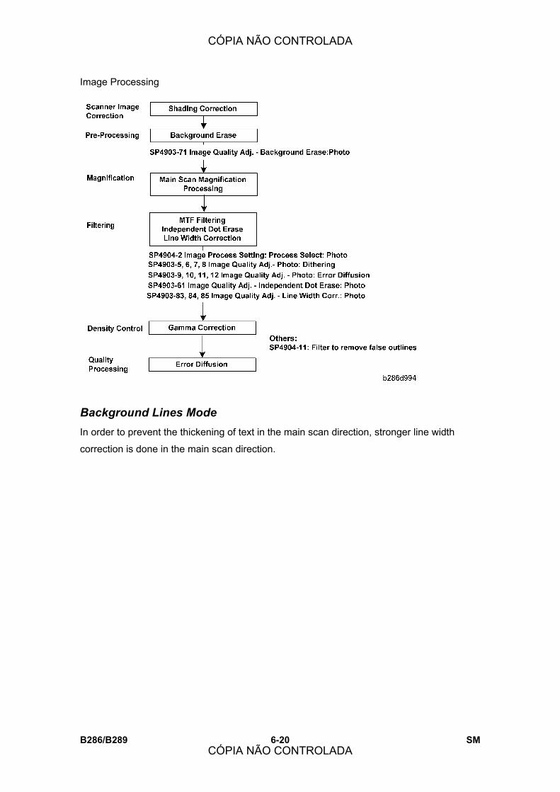
Image Processing
B286/B289 6-20 SM
Background Lines Mode In order to prevent the thickening of text in the main scan direction, stronger line width
correction is done in the main scan direction.
CÓPIA NÃO CONTROLADA
CÓPIA NÃO CONTROLADA
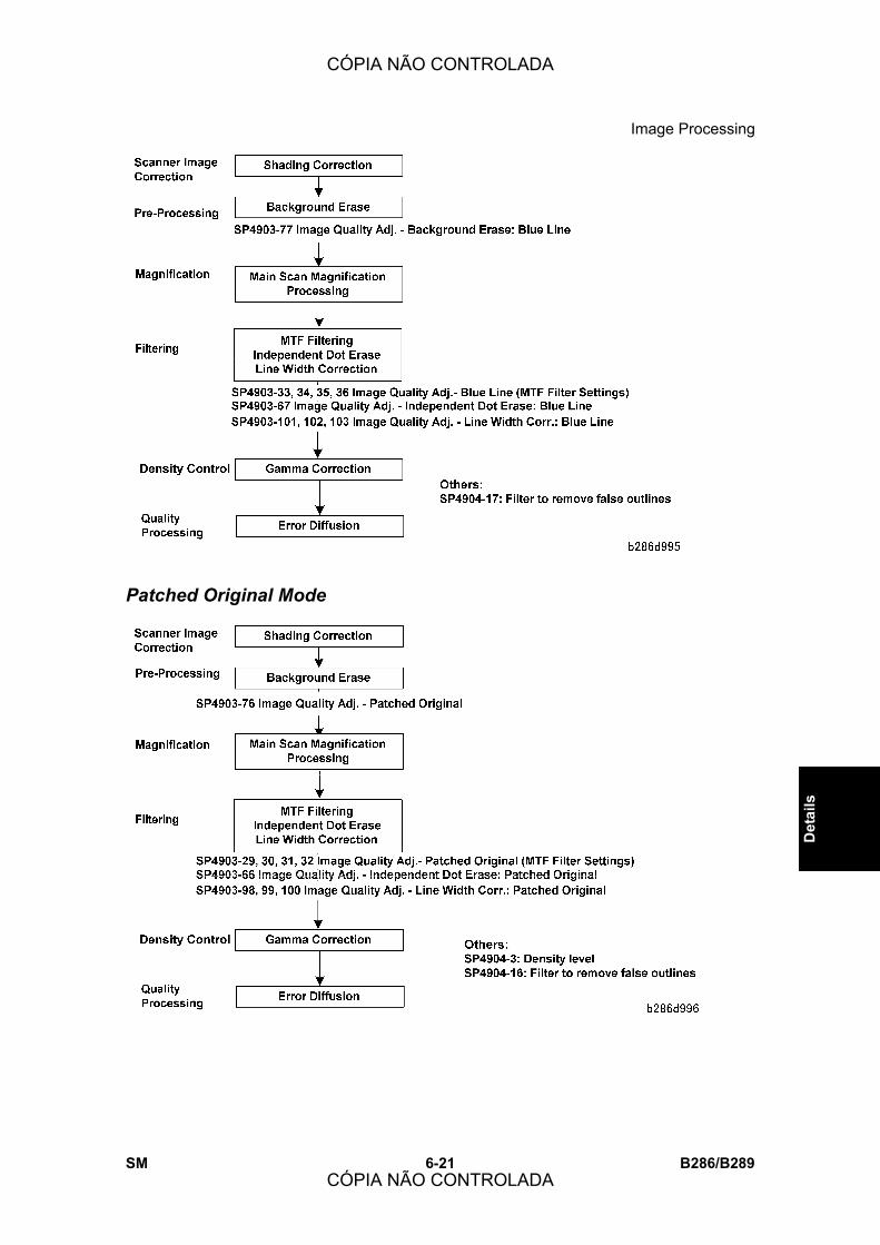
Image Processing
SM 6-21 B286/B289
Det
ails
Patched Original Mode
CÓPIA NÃO CONTROLADA
CÓPIA NÃO CONTROLADA

Image Processing
B286/B289 6-22 SM
Generation Mode
CÓPIA NÃO CONTROLADA
CÓPIA NÃO CONTROLADA
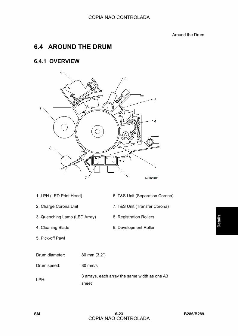
Around the Drum
SM 6-23 B286/B289
Det
ails
6.4 AROUND THE DRUM
6.4.1 OVERVIEW
1. LPH (LED Print Head) 6. T&S Unit (Separation Corona)
2. Charge Corona Unit 7. T&S Unit (Transfer Corona)
3. Quenching Lamp (LED Array) 8. Registration Rollers
4. Cleaning Blade 9. Development Roller
5. Pick-off Pawl
Drum diameter: 80 mm (3.2�)
Drum speed: 80 mm/s
LPH: 3 arrays, each array the same width as one A3
sheet
CÓPIA NÃO CONTROLADA
CÓPIA NÃO CONTROLADA

Around the Drum
B286/B289 6-24 SM
6.4.2 DRUM DRIVE
The drum motor [A] controls:
! Timing gears [B]
! Timing belt and wheel [C]
This turns the OPC drum [D].
Gear [E] (meshed with the OPC drum) turns the cleaning unit auger [F].
When paper feed starts:
! The drum motor switches on and turns the drum forward.
! While the drum turns forward, the LPH writes the ID sensor pattern on the drum, then
the drum turns forward 250 mm more.
! The ID sensor reads the pattern (Vsp) and the surface of the drum (Vsg) to find
Vsp/Vsg for toner density control.
The drum motor turns the drum in the opposite direction at the end of each job for 0.3 s.
This removes paper dust (caused when the paper roll is cut) from the cleaning blade.
CÓPIA NÃO CONTROLADA
CÓPIA NÃO CONTROLADA

Around the Drum
SM 6-25 B286/B289
Det
ails
6.4.3 CHARGE CORONA UNIT
The charge corona unit [A], above the OPC drum, uses the Scorotron (Negative) Charge
Method (! Photocopying Processes � Charge � Corona Charge)
There is one gold-plated charge wire behind some grid wires. The grid wires make sure
that the charge on the OPC drum is constant.
Charges used for this machine:
! Grid: -825 V
! Drum surface: -850 V
! Corona wire: About 1200 μA
CÓPIA NÃO CONTROLADA
CÓPIA NÃO CONTROLADA

Around the Drum
B286/B289 6-26 SM
6.4.4 CORONA WIRE CLEANING
The corona wire is cleaned immediately after the main power switch or operation power
switch is switched on, if these two conditions occur at the same time:
! 600 m of paper fed through the machine since the last wire cleaning
! The temperature of the hot roller is less than 50°C (122°F)).
The interval between automatic wire cleaning (Default: 600 m) can be adjusted with
SP2804. This SP can also be set to clean the corona wire immediately after the machine is
switched on.
The wire cleaner motor [A] controls the cleaning pad [B].
When the cleaning pad gets to the left side (as shown above), the motor changes direction
and pulls the cleaning pad back to the home position on the right.
If the cleaning pad is not at the home position immediately after the main power is switched
on, the cleaning pad goes back to home position.
The actuator [C] for the wire cleaner sensor [D] turns while the cleaner moves. The signals
from this sensor tell the machine when the cleaning pad moves. If the wire cleaner stops
before it gets to the end, or if stops too long at the far left position, the wire cleaner sensor
detects an error.
CÓPIA NÃO CONTROLADA
CÓPIA NÃO CONTROLADA

Around the Drum
SM 6-27 B286/B289
Det
ails
6.4.5 DRUM CLEANING
This machine uses a counter blade system to clean toner from the surface of the drum.
(! Photocopying Processes � Cleaning � Counter Blade)
The cleaning blade [A] is opposite to the direction that the drum turns.
The counter blade has a lever [B] on the bottom side of the upper unit.
! Set [B] to the right: The blade touches the drum for normal operation.
! Set [B] to the left: The blade is away from the drum.
This lever must be set to the left at the following times:
! Before you remove the OPC drum
! Before you move the machine a long distance
! If you will move the machine to a different location on the same floor, then it is not
necessary to move the lever to the left.
CÓPIA NÃO CONTROLADA
CÓPIA NÃO CONTROLADA
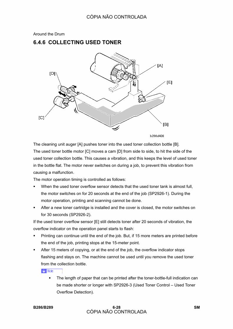
Around the Drum
B286/B289 6-28 SM
6.4.6 COLLECTING USED TONER
The cleaning unit auger [A] pushes toner into the used toner collection bottle [B].
The used toner bottle motor [C] moves a cam [D] from side to side, to hit the side of the
used toner collection bottle. This causes a vibration, and this keeps the level of used toner
in the bottle flat. The motor never switches on during a job, to prevent this vibration from
causing a malfunction.
The motor operation timing is controlled as follows:
! When the used toner overflow sensor detects that the used toner tank is almost full,
the motor switches on for 20 seconds at the end of the job (SP2926-1). During the
motor operation, printing and scanning cannot be done.
! After a new toner cartridge is installed and the cover is closed, the motor switches on
for 30 seconds (SP2926-2).
If the used toner overflow sensor [E] still detects toner after 20 seconds of vibration, the
overflow indicator on the operation panel starts to flash:
! Printing can continue until the end of the job. But, if 15 more meters are printed before
the end of the job, printing stops at the 15-meter point.
! After 15 meters of copying, or at the end of the job, the overflow indicator stops
flashing and stays on. The machine cannot be used until you remove the used toner
from the collection bottle.
! The length of paper that can be printed after the toner-bottle-full indication can
be made shorter or longer with SP2926-3 (Used Toner Control � Used Toner
Overflow Detection).
CÓPIA NÃO CONTROLADA
CÓPIA NÃO CONTROLADA
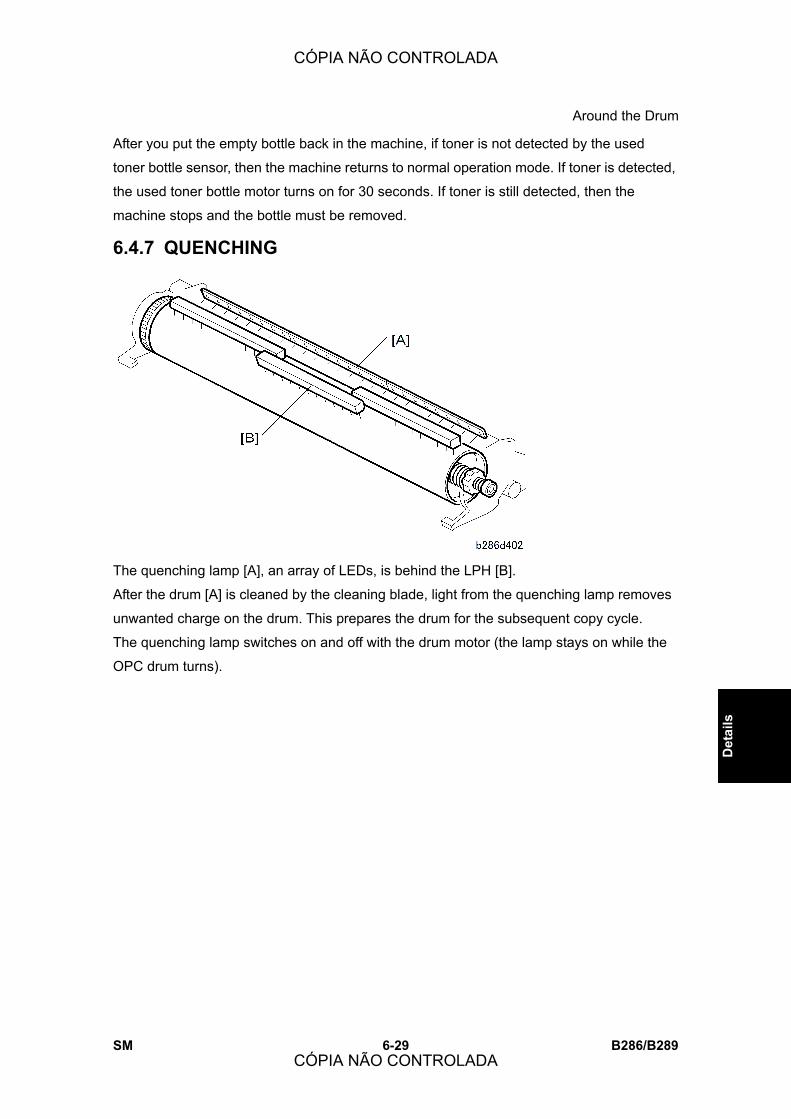
Around the Drum
SM 6-29 B286/B289
Det
ails
After you put the empty bottle back in the machine, if toner is not detected by the used
toner bottle sensor, then the machine returns to normal operation mode. If toner is detected,
the used toner bottle motor turns on for 30 seconds. If toner is still detected, then the
machine stops and the bottle must be removed.
6.4.7 QUENCHING
The quenching lamp [A], an array of LEDs, is behind the LPH [B].
After the drum [A] is cleaned by the cleaning blade, light from the quenching lamp removes
unwanted charge on the drum. This prepares the drum for the subsequent copy cycle.
The quenching lamp switches on and off with the drum motor (the lamp stays on while the
OPC drum turns).
CÓPIA NÃO CONTROLADA
CÓPIA NÃO CONTROLADA
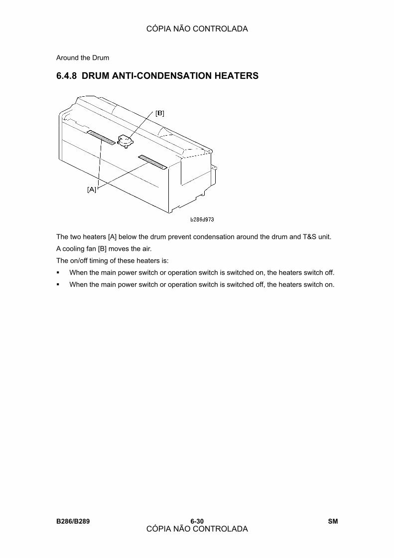
Around the Drum
B286/B289 6-30 SM
6.4.8 DRUM ANTI-CONDENSATION HEATERS
The two heaters [A] below the drum prevent condensation around the drum and T&S unit.
A cooling fan [B] moves the air.
The on/off timing of these heaters is:
! When the main power switch or operation switch is switched on, the heaters switch off.
! When the main power switch or operation switch is switched off, the heaters switch on.
CÓPIA NÃO CONTROLADA
CÓPIA NÃO CONTROLADA

Image Writing
SM 6-31 B286/B289
Det
ails
6.5 IMAGE WRITING
This machine uses an LPH (LED Print Head) [A] that sends light directly to the OPC drum
to make a latent image.
The A0-size 600-dpi print head is an array of connected self-focusing lenses [B] above an
LED array [C] and drive board [D], and attached to a heat sink [E].
! The maximum printing width of the print head is 914 mm (36�).
The LPH has three sections: LPH 1, LPH 2, and LPH 3. The two joints between the
sections are identified as �LPH 1-2� and �LPH-2-3� (see above).
CÓPIA NÃO CONTROLADA
CÓPIA NÃO CONTROLADA
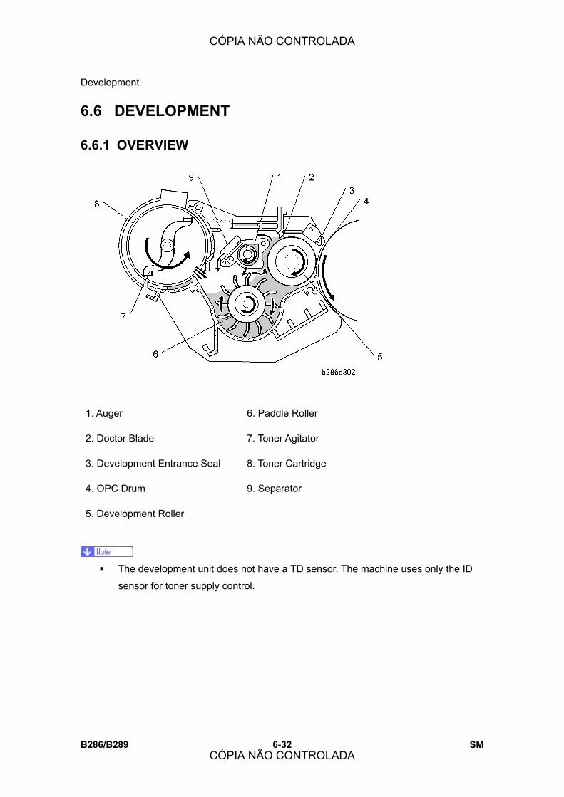
Development
B286/B289 6-32 SM
6.6 DEVELOPMENT
6.6.1 OVERVIEW
1. Auger 6. Paddle Roller
2. Doctor Blade 7. Toner Agitator
3. Development Entrance Seal 8. Toner Cartridge
4. OPC Drum 9. Separator
5. Development Roller
! The development unit does not have a TD sensor. The machine uses only the ID
sensor for toner supply control.
CÓPIA NÃO CONTROLADA
CÓPIA NÃO CONTROLADA

Development
SM 6-33 B286/B289
Det
ails
6.6.2 DEVELOPMENT DRIVE MECHANISM
[A]: Timing belt (from the main motor)
[B]: Gear train
[C]: Paddle roller
[D]: Mixing auger
[E]: Development roller
[F]: Gear
[G]: Toner supply clutch
[H]: Toner agitator shaft (controlled by the toner supply clutch)
The toner supply clutch engages only when toner density control switches on the clutch to
supply toner from the toner cartridge.
The main motor:
! Switches on 1.25 s after the drum motor switches on.
! Turns the development roller at 60 mm/s, to be the same speed as the drum.
! Stops 83 ms (approx. 5 mm turned) after the ID sensor pattern is written during the
initial rotation of the drum motor.
CÓPIA NÃO CONTROLADA
CÓPIA NÃO CONTROLADA

Development
B286/B289 6-34 SM
6.6.3 TONER SUPPLY MECHANISM
This machine uses dual-component development with toner concentration control. The
toner agitator [A] turns in the center of the toner cartridge to move toner to the paddle roller
[B] in the development unit. Toner then goes to the development roller [C] and the drum
[D].To control the quantity of toner that is supplied to the development unit, the machine
switches the toner supply clutch on and off. The output from the ID sensor controls the
clutch on/off timing. This development unit does not have a TD sensor.
CÓPIA NÃO CONTROLADA
CÓPIA NÃO CONTROLADA

Development
SM 6-35 B286/B289
Det
ails
6.6.4 DEVELOPER CROSS-MIXING
(! Photocopying Processes � Development � Crossmixing)
[A]: Doctor blade
[B]: Development roller
[C]: Backspill plate
[D]: Paddle roller
[E]: Auger inlet
[F]: Mixing auger
[G]: Paddle roller inlet
CÓPIA NÃO CONTROLADA
CÓPIA NÃO CONTROLADA

Development
B286/B289 6-36 SM
6.6.5 DEVELOPMENT BIAS
The CGB power pack [A] applies a negative bias (-650V) to the development roller [B],
slightly higher than the remaining charge on the drum.
The development bias during copying is set by SP 2201-1 (Development Bias Adjustment �
Image Area).
CÓPIA NÃO CONTROLADA
CÓPIA NÃO CONTROLADA

Development
SM 6-37 B286/B289
Det
ails
6.6.6 ID SENSOR
The ID sensor [A] regularly reads two areas of the drum:
! Bare surface of the drum. The ID sensor measures the reflectivity of the bare drum,
converts this reading to a voltage, and stores this value (Vsg) in NVRAM.
! ID sensor pattern. The LPH writes an ID sensor pattern on the drum. The ID sensor
reads the density of this pattern, converts it to a voltage, and stores this value (Vsp) in
NVRAM.
The machine makes an ID sensor pattern to read Vsp after each copy.
But, the machine reads Vsg only one time. This is done during machine warm-up (see the
next section).
CÓPIA NÃO CONTROLADA
CÓPIA NÃO CONTROLADA

Development
B286/B289 6-38 SM
6.6.7 WARMUP CONTROL (VSG CORRECTION)
In order to prevent the occurrence of dirty background on the first copy after the machine
warms up, the value of Vsg is checked after the upper unit is closed and after the machine
is turned on (or returns from low power mode).
After Closing the Upper Unit The machine measures Vsg after the upper unit is closed, and recalibrates the ID sensor if
necessary.
! If the machine detects Vsg < 2.5 V twice, the machine issues SC401 (ID Sensor Vsg
Error.
! If the machine detects Vsg > 2.5 V, it will perform adjustments or issue SC401 as
shown below, based on the value of the Vsg reading. (See the �ID Sensor
Recalibration Table� below.)
After Power On
If the fusing temperature is below 50°C (122°F) after the machine is powered on (or returns
from the low power mode), the machine measures Vsg. The machine compares this Vsg
reading with the PWM value that was stored when the ID sensor was initialized, in order to
determine if the current Vsg value is correct.
! If the machine detects Vsg < 2.5 V twice, the machine issues SC401 (ID Sensor Vsg
Error.
! If the machine detects Vsg > 2.5 V, it will perform adjustments or issue SC401 as
shown below, based on the value of the Vsg reading.
ID Sensor Recalibration
Readings (V) How the ID Sensor is Recalibrated
Vsg < 3.9 PWM value +0.5%
Vsg = 3.9 to 4.10 ID sensor is re-calibrated automatically with the stored
PWM value.
Vsg = 4.1 to 4.2 PWM value -0.2%
Vsg = 4.2 to 4.5 PWM value -0.5%
Vsg = 4.5 to 4.8 PWM value -1.0%
Vsg > 4.8 SC401 occurs (ID Sensor Vsg Error). For more details see
section 4.2 �SC Code Descriptions.�
CÓPIA NÃO CONTROLADA
CÓPIA NÃO CONTROLADA
Development
SM 6-39 B286/B289
Det
ails
! If SP2804 is set to clean the charge corona wire during warm-up, Vsp/Vsg is
measured after the wire is cleaned.
! The machine measures Vsg after the machine is powered on or returns from the
low power mode, if SP2924 is set to �0� or �1.� (The default is �0�, which means
that the machine measures Vsg after power on when the fusing temperature is
below 50°C.) For more, refer to �Service Tables.�
! If the machine is switched off and on after the warm-up sequence when Vsg is less
than 2.5V, the warm-up sequence is done, and the setting of SP2924 (Warm-up
Control) is ignored.
6.6.8 TONER DENSITY CONTROL
Overview This machine uses an ID sensor to control:
! Toner density
! Toner near end detection
! Toner end detection
The machine uses the ratio of Vsg/Vsp to find the quantity of toner that must be supplied to
the drum.
To supply toner, the machine switches on the toner supply clutch to feed toner from the
toner cartridge to the development unit.
SP3103 (ID Sensor Output Display) shows the most recent values of Vsg and Vsp that
were stored in the NVRAM (Range: 0.00 ∼ 5.00 V).
Supply Modes There are two supply modes
! Detect Supply Mode
! Fixed Supply Mode
During normal operation, the machine uses detect supply mode.
Detect supply mode has two sub-modes (referred to as �tables�).
! Main table: Used during copying
! Length table: The machine switches to this table during copying if the length of the
copy becomes more than 1189 mm (46.8�).
If an ID sensor problem occurs during the job, the machine stops the end of the job. The
machine does not go into fixed supply mode automatically. The technician must repair the
machine. If the machine cannot be repaired, the technician must put the machine into fixed
supply mode with SP 2208-3.
CÓPIA NÃO CONTROLADA
CÓPIA NÃO CONTROLADA

Development
B286/B289 6-40 SM
In fixed supply mode, the machine supplies a set quantity of toner per page.
After the technician repairs the machine, the machine must be put back in detect supply
mode with SP 2208-3.
Detect Supply Mode � Main Table - The machine uses this table from the start of the page until the length of the printed page
gets to 1189 mm (46.8�).
The machine uses these two parameters to control the rate of toner supply:
! Vsg/Vsp
! The toner supply level set with SP2208-1
Toner Supply Level (SP 2208 001) Vsp/Vsg
L M H HH
Less than 10% None None None None
10% to 12% 15% 20% 30% 40%
More than 12% 40% 50% 60% 70%
Toner Near-End 100% 100% 100% 100%
� Length Table - If the page becomes longer than 1189 mm (46.8�), the machine changes to the Length
Table for the remaining part of the page.
But, if no toner was supplied before the start of the copy job, the quantity of toner was
sufficient at that time. Because of this, the machine does not change to the Length Table.
The Length Table ignores the Vsp/Vsg ratio. Toner is supplied at a set rate. This rate is
controlled by the toner supply level set with SP 2208-1.
Length Table
CÓPIA NÃO CONTROLADA
CÓPIA NÃO CONTROLADA
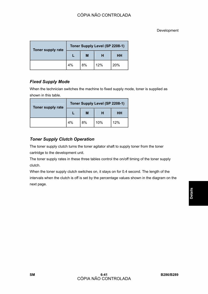
Development
SM 6-41 B286/B289
Det
ails
Toner Supply Level (SP 2208-1) Toner supply rate
L M H HH
4% 8% 12% 20%
Fixed Supply Mode When the technician switches the machine to fixed supply mode, toner is supplied as
shown in this table.
Toner Supply Level (SP 2208-1) Toner supply rate
L M H HH
4% 8% 10% 12%
Toner Supply Clutch Operation The toner supply clutch turns the toner agitator shaft to supply toner from the toner
cartridge to the development unit.
The toner supply rates in these three tables control the on/off timing of the toner supply
clutch.
When the toner supply clutch switches on, it stays on for 0.4 second. The length of the
intervals when the clutch is off is set by the percentage values shown in the diagram on the
next page.
CÓPIA NÃO CONTROLADA
CÓPIA NÃO CONTROLADA
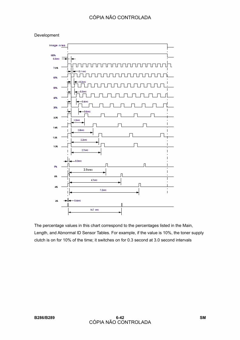
Development
B286/B289 6-42 SM
The percentage values in this chart correspond to the percentages listed in the Main,
Length, and Abnormal ID Sensor Tables. For example, if the value is 10%, the toner supply
clutch is on for 10% of the time; it switches on for 0.3 second at 3.0 second intervals
CÓPIA NÃO CONTROLADA
CÓPIA NÃO CONTROLADA
Development
SM 6-43 B286/B289
Det
ails
6.6.9 TONER END/NEAR-END DETECTION
The machine compares Vsp/Vsg with two SP settings to find when the toner cartridge is
almost empty (Toner Near End) or fully empty (Toner End).
! SP2927-1: Toner near-end
! SP2927-3: Toner end
Toner Near End When Vsp/Vsg is larger than SP2927-1 three times in sequence, the machine shows a
toner near-end indication. The default is 0.145. If the setting is higher, the quantity of toner
in the cartridge becomes less before toner near-end occurs. This can cause paler images
at the end of the toner cartridge�s life. When toner near-end occurs, the toner near-end
indicator lights on the operation panel.
Toner End When Vsp/Vsg is larger than the setting for SP2927-3 (Default: 0.165) three pages in a row,
the machine prints one more page and then stops immediately.
When toner end occurs, the toner end indicator lights on the operation panel and copying
stops. The machine cannot be used until:
! A new toner cartridge is installed.
! The machine recovers from toner end.
Toner End Recovery The flow chart on the next page shows the recovery sequence when a new toner cartridge
is installed after toner end occurs. After toner end occurs, toner end recovery starts if you
open and close the toner hopper cover.
The machine makes an ID sensor pattern to detect if a supply of toner is available. If
Vsp/Vsg is less than Vref, then the machine detects recovery from toner end, and goes out
from the toner end condition. If Vsp/Vsg is more than Vref 5 times, then the machine stays
in the toner end condition, and it cannot be used. In some conditions, the machine recovers
from toner end if you switch the machine off and on.
CÓPIA NÃO CONTROLADA
CÓPIA NÃO CONTROLADA
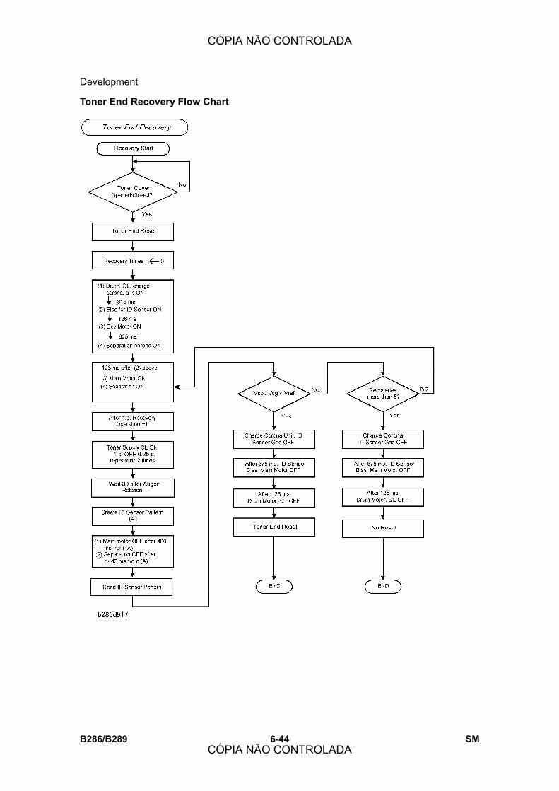
Development
B286/B289 6-44 SM
Toner End Recovery Flow Chart
CÓPIA NÃO CONTROLADA
CÓPIA NÃO CONTROLADA
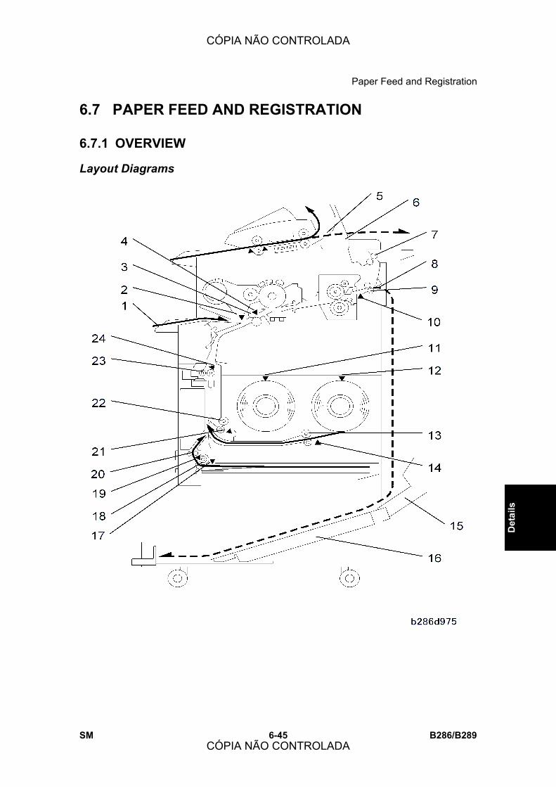
Paper Feed and Registration
SM 6-45 B286/B289
Det
ails
6.7 PAPER FEED AND REGISTRATION
6.7.1 OVERVIEW
Layout Diagrams
CÓPIA NÃO CONTROLADA
CÓPIA NÃO CONTROLADA

Paper Feed and Registration
B286/B289 6-46 SM
1. Manual Feed Table (Bypass) 13. Feed Rollers (Roll 2)
2. Paper Set Sensor 14. Roll 2 Paper End Sensor
3. Registration Rollers 15. Lower Output Tray
4. Registration Sensor 16. Lower Output Stacker
5. Upper Exit 17. Paper Cassette Paper End Sensor
6. Paper Junction Gate 18. Paper Cassette Feed Roller
7. Upper Exit Rollers 19. Relay Sensor (Cut Sheet)
8. Rear Exit 20. Grip Rollers
9. Fusing Exit Rollers 21. Roll 1 Paper End Sensor
10. Exit Sensor 22. Feed Rollers (Roll 1)
11. Roll 1 End Sensor 23. RF Exit Rollers
12. Roll 2 End Sensor 24. RF Exit Sensor
CÓPIA NÃO CONTROLADA
CÓPIA NÃO CONTROLADA

Paper Feed and Registration
SM 6-47 B286/B289
Det
ails
This diagram shows all the rollers and sensors used during paper transport. The diagram is
not in scale.
Feed Station Overview The machine can feed paper from the manual feed table or the optional roll feeder. With all
options installed, there are four paper feed sources:
! Manual Feed Table (bypass tray)
! Roll 1: Front roll in the Roll Feeder (Roll Feeder B851 has the front roll only)
! Roll 2: Rear roll in the Roll Feeder (Roll Feeder B852 has the front and rear rolls).
! Paper Cassette (installed in the bottom of the Roll Feeder)
The user sets one of these paper feed sources at the operation panel.
When the machine detects the original, the feed motor and the registration motor start, and
paper feed starts. The paper goes into the machine from the paper supply source, goes
through the RF exit rollers, and then to the registration rollers.
The registration rollers stop temporarily for paper skew correction, and then start again to
feed the paper to the drum.
CÓPIA NÃO CONTROLADA
CÓPIA NÃO CONTROLADA
Paper Feed and Registration
B286/B289 6-48 SM
Manual Feed Table The manual feed table (bypass tray) is the main station for paper supply for this machine.
(The roll feeder and paper cassette are options.) Because of this, the manual feed table is
not a �bypass� tray, although the name for the manual feed table is �bypass tray� in the
User Tools menus.
The manual feed table feeds one pre-cut sheet.
Roll Feeder The cutter cuts the paper after the machine feeds the specified paper length. The RF exit
sensor monitors paper feed.
The start time of the cutter is controlled by the cutting mode set by the user at the operation
panel:
! Preset 1. Cuts a preset SEF length. The size of the original is ignored.
! Preset 2. Cuts a preset LEF length. The size of the original is ignored.
! Synchro. Cuts the copy paper to the same length as the original.
! Variable. Cuts the copy to the length that was input at the operation panel.
After the last cut of a job, the feed roller changes direction and feeds the leading edge of
the paper to its home position. This makes sure that the paper path is not blocked when
paper feed starts for the next job.
Paper Cassette The optional universal-type paper cassette, installed in the bottom of the roll feeder, feeds
cut sheets.
Paper Width and Type Settings After a roll is installed, the width of the paper and the type of paper must be set. For more,
see section 1.2 �Main Machine Installation (B286).�
CÓPIA NÃO CONTROLADA
CÓPIA NÃO CONTROLADA

Paper Feed and Registration
SM 6-49 B286/B289
Det
ails
6.7.2 MANUAL FEED MECHANISM
The user puts a cut sheet [A] on the manual feed table (also known as the bypass tray).
The paper set sensor [B] detects the leading edge of the sheet. This switches on the drum
motor, main motor, and registration clutch.
The registration clutch engages the registration roller [C] which feeds the sheet.
The registration sensor [D] detects the edge of the sheet and the registration clutch
switches off for 2 seconds. This gives the user time to adjust the position of the paper to
make it straight.
The 2-second interval can be adjusted with SP1911 (By-Pass Feed Start Timing Adj.).
CÓPIA NÃO CONTROLADA
CÓPIA NÃO CONTROLADA
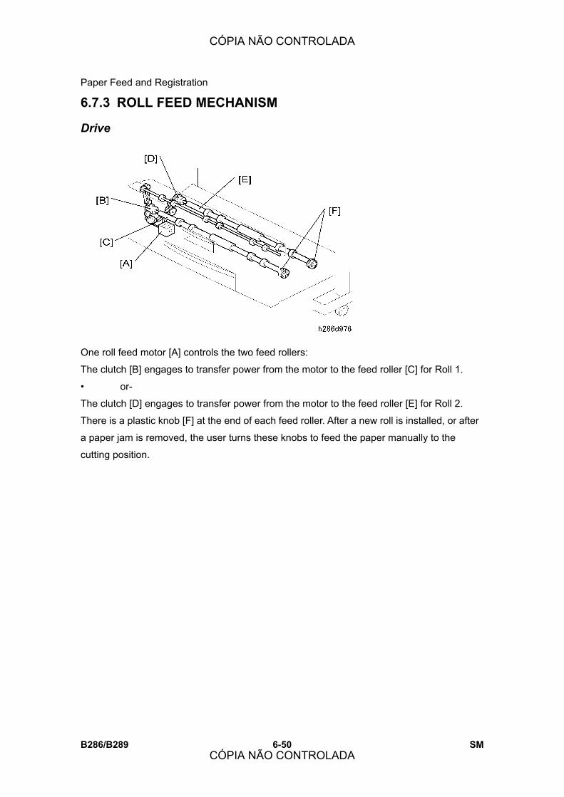
Paper Feed and Registration
B286/B289 6-50 SM
6.7.3 ROLL FEED MECHANISM
Drive
One roll feed motor [A] controls the two feed rollers:
The clutch [B] engages to transfer power from the motor to the feed roller [C] for Roll 1.
� or-
The clutch [D] engages to transfer power from the motor to the feed roller [E] for Roll 2.
There is a plastic knob [F] at the end of each feed roller. After a new roll is installed, or after
a paper jam is removed, the user turns these knobs to feed the paper manually to the
cutting position.
CÓPIA NÃO CONTROLADA
CÓPIA NÃO CONTROLADA

Paper Feed and Registration
SM 6-51 B286/B289
Det
ails
Roll Pre-feeding
Check Before Pre-Feeding
The machine does a pre-feed control check:
! Immediately after the main power switch or operation switch is switched on.
! Immediately after the roll feeder drawer is closed.
! At the end of a copy job.
During the pre-feed check, the cutter moves to home position:
! The machine checks if the left or right cutter HP switch is ON.
! If the two cutter sensors are OFF, the machine moves the cutter to the left home
position. This makes sure that the spring-loaded paper holder opens to let paper feed.
(See section 6.7.5 �Roll Paper Cutting Mechanism.�)
The machine pre-feeds paper from each roll after the pre-feed check completes without
error. Pre-feeding is done for Roll 1 first.
CÓPIA NÃO CONTROLADA
CÓPIA NÃO CONTROLADA
Paper Feed and Registration
B286/B289 6-52 SM
Roll 1 Pre-Feeding
! Roll feed clutch 1 engages and turns the Roll 1 feed roller.
! The leading edge of the sheet feeds past the RF exit sensor [A].
! Feed stops.
! The roll feed motor pulls back the leading edge of the sheet until it is 55 mm below the
cutter. Then it stops. This is the pre-feed position [B] for Roll 1.
Roll 2 Pre-Feeding
! The machine pre-feeds the sheet from Roll 2.
! The roll feed motor pulls back the leading edge of the sheet until it is 60 mm below the
cutter and then stops. This is the pre-feed position [C] for Roll 2.
The two sheets stay at their pre-feed positions for the start of the next copy job. There are
no rollers in this part of the paper path. As a result, when the two rolls are at the pre-feed
positions, one can easily feed, and the other does not move.
CÓPIA NÃO CONTROLADA
CÓPIA NÃO CONTROLADA

Paper Feed and Registration
SM 6-53 B286/B289
Det
ails
Roll Paper Feed
Roll paper feed starts from the pre-feed position.
! The roll feed motor engages roll feed clutch 1 and turns the feed rollers [1].
! The RF exit rollers [2] feed the paper past the roll exit sensor [3] to the registration
roller. The RF exit sensor checks that the leading and trailing edges of the sheet go by
at the correct time.
! The registration sensor [4] stops the registration roller [5] to correct skew. Then, the
registration roller feeds the paper to the drum [6] and through the T&S unit [7].
! The cutter [8] cuts the paper at the length specified for the job. (See section 6.7.5 �Roll
Paper Cutting Mechanism.�)
! The rollers in the fusing unit [9] feed the sheet to the exit rollers [10].
! The exit sensor [11] checks that the leading and trailing edges of the sheet go by at the
correct time.
! The exit rollers feed the sheet to the paper junction gate [12].
! The paper junction gate sends the paper to the upper exit rollers [13] or sends it out the
rear [14] of the machine. (see section 6.10.2 �Switching the Paper Exit.�)
CÓPIA NÃO CONTROLADA
CÓPIA NÃO CONTROLADA

Paper Feed and Registration
B286/B289 6-54 SM
6.7.4 ROLL FEEDER PAPER HOLDERS
The racks [A] hold the rolls that are adjustable. This lets the user install paper rolls of
different widths.
A roll stopper [B] is put in each end of a roll. The roll lever [C] locks the stoppers in their
position after they are put in the ends of a roll. The roll is put on the rack with each stopper
locked in its position.
CÓPIA NÃO CONTROLADA
CÓPIA NÃO CONTROLADA
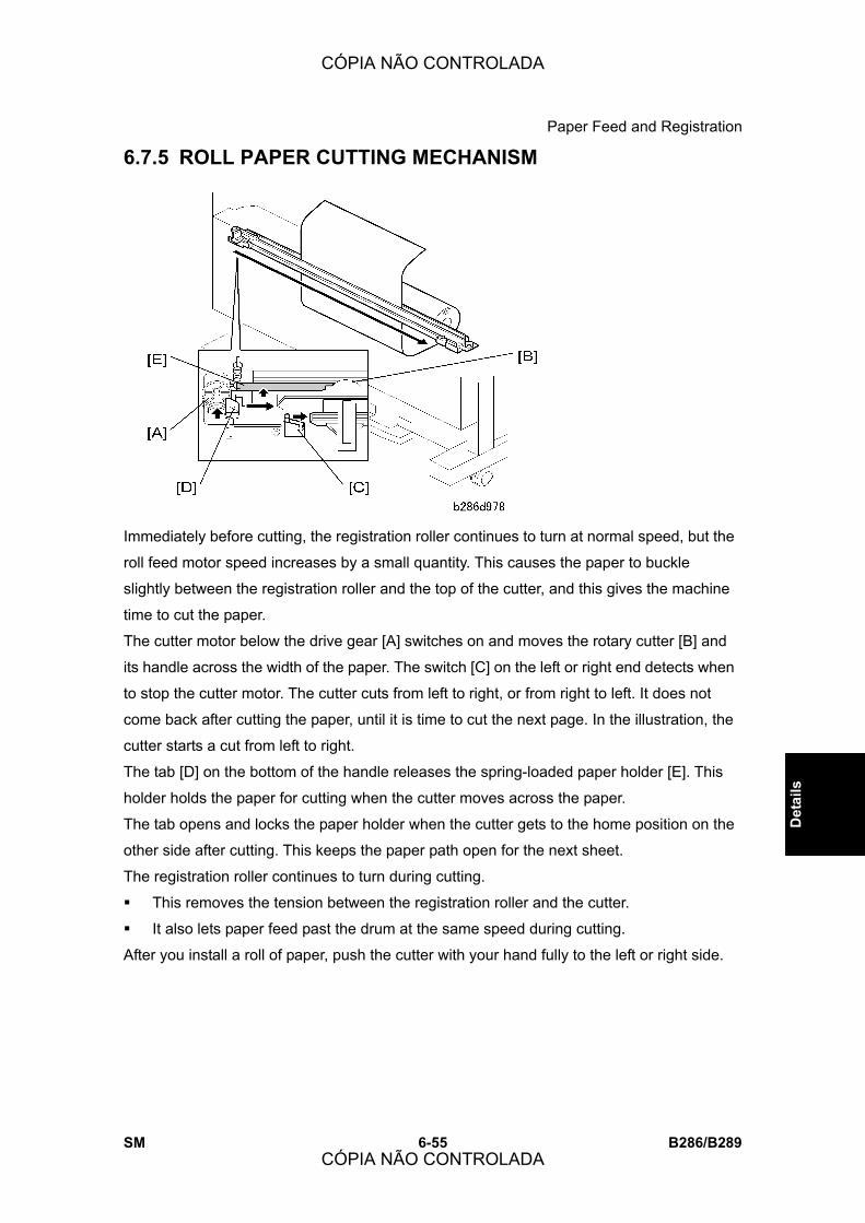
Paper Feed and Registration
SM 6-55 B286/B289
Det
ails
6.7.5 ROLL PAPER CUTTING MECHANISM
Immediately before cutting, the registration roller continues to turn at normal speed, but the
roll feed motor speed increases by a small quantity. This causes the paper to buckle
slightly between the registration roller and the top of the cutter, and this gives the machine
time to cut the paper.
The cutter motor below the drive gear [A] switches on and moves the rotary cutter [B] and
its handle across the width of the paper. The switch [C] on the left or right end detects when
to stop the cutter motor. The cutter cuts from left to right, or from right to left. It does not
come back after cutting the paper, until it is time to cut the next page. In the illustration, the
cutter starts a cut from left to right.
The tab [D] on the bottom of the handle releases the spring-loaded paper holder [E]. This
holder holds the paper for cutting when the cutter moves across the paper.
The tab opens and locks the paper holder when the cutter gets to the home position on the
other side after cutting. This keeps the paper path open for the next sheet.
The registration roller continues to turn during cutting.
! This removes the tension between the registration roller and the cutter.
! It also lets paper feed past the drum at the same speed during cutting.
After you install a roll of paper, push the cutter with your hand fully to the left or right side.
CÓPIA NÃO CONTROLADA
CÓPIA NÃO CONTROLADA

Paper Feed and Registration
B286/B289 6-56 SM
6.7.6 ROLL END DETECTION
To detect roll end, these two reflective photo-sensors detect the black core of an empty roll:
! Roll end sensor 1 [A], above Roll 1
! Roll end sensor 2 [B], above Roll 2
CÓPIA NÃO CONTROLADA
CÓPIA NÃO CONTROLADA

Paper Feed and Registration
SM 6-57 B286/B289
Det
ails
Also, two other sensors detect roll end if the core of the paper roll is a color other than
black:
! Roll end sensor 3 (EXP) [C] detects the trailing edge of the roll when roll 1 has no more
paper.
! Roll end sensor 4 (EXP) [D] detects the trailing edge of the roll when roll 2 has no more
paper.
The machine also detects roll end if the RF exit sensor [E] does not detect a leading edge
after paper feed starts.
! If the leading edge of the sheet does not get to the paper exit sensor from Roll 1 in 3.2
seconds or less, the machine detects paper end (or roll not installed).
! If the leading edge of the sheet does not get to the paper exit sensor from Roll 2 in 6.7
seconds or less, the machine detects paper end (or roll not installed).
CÓPIA NÃO CONTROLADA
CÓPIA NÃO CONTROLADA

Paper Feed and Registration
B286/B289 6-58 SM
6.7.7 PAPER CASSETTE MECHANISM
Support arms [A] on each side of the paper cassette go in grooves on each side when the
paper cassette is set in the roll feeder.
The grooves lift the supports and pull the springs attached to the bottom plate [B] of the
paper cassette. This gives sufficient tension to keep the stack of paper on the bottom plate
at the correct height for paper feed.
The cassette feed motor turns the cassette feed roller [C] to feed paper from the top of the
stack.
A friction pad [D] below the feed roller gives sufficient friction to stop sheets from double
feeding.
The grip rollers [E] (also driven by the cassette feed motor), pull the paper into the paper
feed path and feed it up to the RF exit rollers.
CÓPIA NÃO CONTROLADA
CÓPIA NÃO CONTROLADA

Paper Feed and Registration
SM 6-59 B286/B289
Det
ails
6.7.8 PAPER CASSETTE FEED
Cassette Paper Path
Paper feeds from the paper cassette when the copy job starts.
The cassette feed motor [A] switches on, and the cassette feed clutch [B] engages to turn
the cassette feed roller [C] and the grip rollers [D].
The cassette relay sensor [E]:
! Detects the leading edge of the sheet.
! Switches off the cassette feed clutch.
! The grip rollers [D] continue to turn, and they feed the paper into the same paper path
used by roll feed.
! The cassette relay sensor also detects paper jams.
! After the cassette feed clutch switches off, the cassette feed roller continues to
touch the paper. But, the pressure is very weak. Because of this, the grip rollers
can pull the paper out easily.
After the grip rollers pull the paper out of the paper cassette, the transport sequence is the
same as the roll paper path (the paper is not cut). Refer to the previous page.
The cassette set sensor [F] detects paper after the paper cassette is pulled out or is not
correctly locked in its position.
CÓPIA NÃO CONTROLADA
CÓPIA NÃO CONTROLADA

Paper Feed and Registration
B286/B289 6-60 SM
Paper Cassette Pre-Feeding Paper does not pre-feed from the cassette before the copy job starts. The machine
pre-feeds paper from the cassette only between pages of multi-page copy jobs.
There are two pre-feed positions for the leading edge of cut sheets after the first sheet of a
multi-page copy job. The length of the paper in the cassette controls the pre-feed position.
! Pre-feed position 1 [A] is 234.8 mm below the RF exit sensor [B]. This is for cut sheets
18.7 inches (457.2 mm) long. (This is the maximum length for the paper cassette.)
! Pre-feed position 2 [C] is 184.4 mm below the RF exit sensor. This is for cut sheets
less than 18.7 inches long.
Position 1 (lower than Position 2) is used for longer paper. This prevents overlap between
the leading edge of a sheet and the trailing edge of the sheet before it.
CÓPIA NÃO CONTROLADA
CÓPIA NÃO CONTROLADA

Paper Feed and Registration
SM 6-61 B286/B289
Det
ails
6.7.9 PAPER CASSETTE PAPER END DETECTION
The paper end sensor [A] is above the paper cassette.
The feeler [B] falls through a hole in the cassette plate after the last sheet feeds from the
cassette. The actuator [C] moves forward away from the sensor and the machine detects
paper end.
The cassette sensor [D] detects when the paper cassette is set and locked in its position.
CÓPIA NÃO CONTROLADA
CÓPIA NÃO CONTROLADA
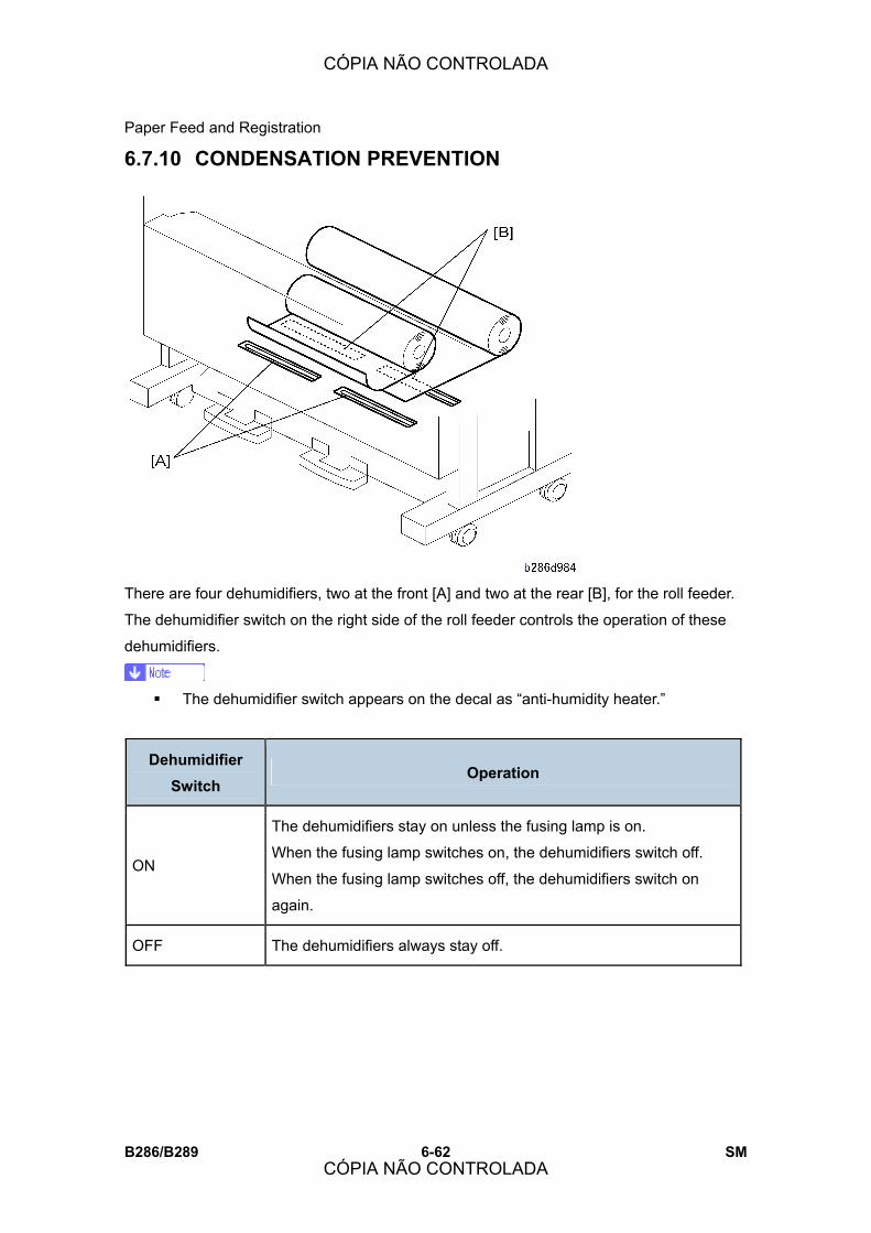
Paper Feed and Registration
B286/B289 6-62 SM
6.7.10 CONDENSATION PREVENTION
There are four dehumidifiers, two at the front [A] and two at the rear [B], for the roll feeder.
The dehumidifier switch on the right side of the roll feeder controls the operation of these
dehumidifiers.
! The dehumidifier switch appears on the decal as �anti-humidity heater.�
Dehumidifier Switch
Operation
ON
The dehumidifiers stay on unless the fusing lamp is on.
When the fusing lamp switches on, the dehumidifiers switch off.
When the fusing lamp switches off, the dehumidifiers switch on
again.
OFF The dehumidifiers always stay off.
CÓPIA NÃO CONTROLADA
CÓPIA NÃO CONTROLADA

Paper Feed and Registration
SM 6-63 B286/B289
Det
ails
6.7.11 PAPER REGISTRATION
The main motor [A] and registration clutch [B] control the registration roller [C].
The registration clutch switches off temporarily for roll paper or cut sheets from the paper
cassette.
! When paper is fed from the roll feeder or paper cassette, the paper buckles paper
against the roller to remove skew.
! When paper is fed from the manual feed table, feed stops for 2 seconds to let the user
correct the paper position, to prevent skew (see section 6.7.2 �Manual Feed
Mechanism�). The 2-second interval can be adjusted with SP1911 (By-Pass Feed Start
Timing Adj.).
Then the registration clutch switches on again to feed the paper to the drum.
CÓPIA NÃO CONTROLADA
CÓPIA NÃO CONTROLADA

Image Transfer and Separation
B286/B289 6-64 SM
6.8 IMAGE TRANSFER AND SEPARATION
6.8.1 OVERVIEW
The T&S unit contains two parts:
[A] Transfer corona unit
[B] Separation corona unit
Transfer Corona Unit Uses a tungsten wire (diameter 80 μm) 9.6 mm below the drum. This wire applies approx.
60 μA to transfer toner from the drum to the paper.
Transfer method: Scorotron charger
Entrance guides:
2 Guide plates: The first is a conductive mylar and guide plate, and
the second is a conductive mylar and leaf spring. They are 0.85 mm
above the drum.
CÓPIA NÃO CONTROLADA
CÓPIA NÃO CONTROLADA

Image Transfer and Separation
SM 6-65 B286/B289
Det
ails
Separation Corona Unit Applies approx. ac 280 μA and dc �25 μA to pull the paper off the drum.
Separation method: Wide angle AC Scorotron charger
Backup separation: Pick-off pawl, pick-off pawl solenoid
6.8.2 PICK-OFF PAWL OPERATION
The pick-off pawls separate paper from the drum if the separation corona does not
separate the paper fully.
The pick-off pawl solenoid [A] moves the pick-off pawls [B] until they touch the drum.
When the leading edge of the paper on the drum goes into the separation corona unit, the
solenoid switches on. About 198 mm (7.8�) of the paper touches the drum. The pick-off
pawl shaft starts to turn, and the pawls on the shaft are held against the drum by a spring.
CÓPIA NÃO CONTROLADA
CÓPIA NÃO CONTROLADA

Fusing Unit
B286/B289 6-66 SM
6.9 FUSING UNIT
6.9.1 OVERVIEW
1. Hot Roller 8. Pressure Release Lever
2. Fusing Cleaning Roller 9. Pressure Roller
3. Hot Roller Strippers 10. Entrance Spurs
4. Fusing Exit Rollers 11. Fusing Lamp
5. Fusing Exit Sensor 12. Thermostats
6. Pressure Roller Strippers 13. Hot Roller Thermistor
7. Pressure Roller Thermistors (Center, End)
The hot roller wall thickness is 1.3 mm. As a result, warm-up time is short (less than 120 s
from 23°C).
CÓPIA NÃO CONTROLADA
CÓPIA NÃO CONTROLADA

Fusing Unit
SM 6-67 B286/B289
Det
ails
6.9.2 PAPER FEED THROUGH THE FUSING UNIT
After separation from the drum:
! The paper feeds to the transport plate [1].
! The 5 sets of spurs [2] at the entrance hold the paper against the transport plate
! The heat and pressure of the hot roller [3] against the pressure roller [4] fuse the image
to the paper.
! The fusing lamp [5] in the center of the hot roller is pre-heated to the correct
temperature. (It switches on and off to keep the rollers at the correct operating
temperature.)
! The hot roller strippers [6] pull the copy off the hot roller.
! The fusing exit sensor [7] detects the leading edge and trailing edge of the sheet, and
checks the timing to detect paper jams.
! The fusing exit rollers [8] feed the paper out of the fusing unit.
CÓPIA NÃO CONTROLADA
CÓPIA NÃO CONTROLADA

Fusing Unit
B286/B289 6-68 SM
6.9.3 FUSING PRESSURE CONTROL MECHANISM
The spring-loaded pressure levers [A] are attached to the pressure roller shaft [B].
The pressure of the springs pushes the pressure roller [C] (a silicone-rubber roller) against
the hot roller [D].
To adjust the position of the pressure spring [E], change the position of the lower
attachment point:
! Center: Standard tension (60 N on each spring), standard pressure.
! Left: Less tension, less pressure. Set to this position to decrease wrinkling
! Right: More tension, more pressure. Can make better fusing with thick paper.
! Wrinkling occurs more frequently for some types of media (plain, translucent, film,
thick paper).
CÓPIA NÃO CONTROLADA
CÓPIA NÃO CONTROLADA

Fusing Unit
SM 6-69 B286/B289
Det
ails
6.9.4 HOT ROLLER THERMISTORS AND THERMOSTATS
Three thermistors monitor the temperature of the hot roller and pressure roller:
! Thermistor [A] monitors the temperature of the hot roller.
! Two thermistors [B] monitor the temperature of the pressure roller. One thermistor is at
the center of the pressure roller and the other is near the end of the pressure roller.
Thermostat [C] (199°C) and thermostat [D] (200°C) give emergency heat protection. If one
of the thermistors breaks, one of the thermostats will cut power to the fusing lamp. Also,
interlock switches cut power to the fusing circuit when a cover is opened.
6.9.5 TEMPERATURE CONTROL
Paper Thickness Setting To achieve and maintain optimum fusing, the operator must select on the operation panel
the proper setting for the thickness of the paper. This ensures that the machine sets and
maintains the correct target temperatures for the hot roller and pressure roller during the
job.
! Strict control of the fusing temperature is necessary to prevent wrinkling that can
occur at high temperatures with different types of paper.
Changing the paper thickness default setting can improve results if copy images are
blurred or wrinkled. The paper thickness default setting screen can be opened by the
operator with the User Tool:
[User Tools] > �System Settings� > �Tray Paper Settings� > �Paper Thickness� > �Paper
Tray� or �Bypass.�
CÓPIA NÃO CONTROLADA
CÓPIA NÃO CONTROLADA
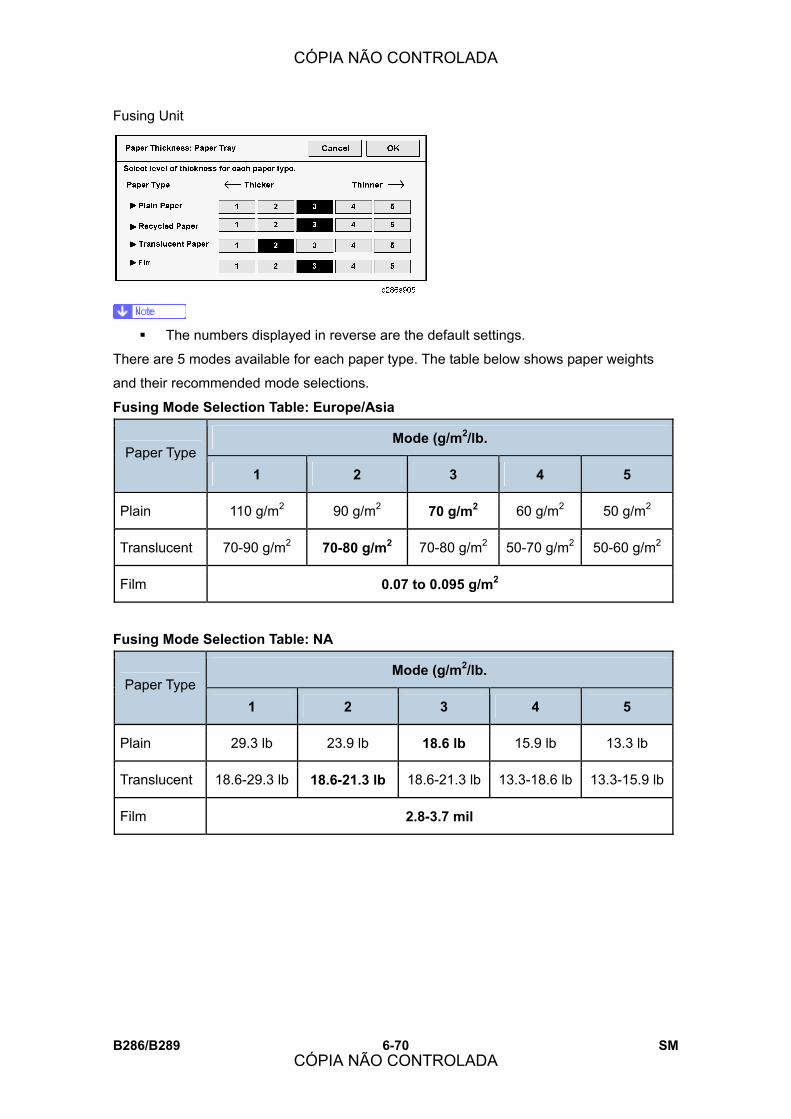
Fusing Unit
B286/B289 6-70 SM
! The numbers displayed in reverse are the default settings.
There are 5 modes available for each paper type. The table below shows paper weights
and their recommended mode selections.
Fusing Mode Selection Table: Europe/Asia
Mode (g/m2/lb. Paper Type
1 2 3 4 5
Plain 110 g/m2 90 g/m2 70 g/m2 60 g/m2 50 g/m2
Translucent 70-90 g/m2 70-80 g/m2 70-80 g/m2 50-70 g/m2 50-60 g/m2
Film 0.07 to 0.095 g/m2
Fusing Mode Selection Table: NA
Mode (g/m2/lb. Paper Type
1 2 3 4 5
Plain 29.3 lb 23.9 lb 18.6 lb 15.9 lb 13.3 lb
Translucent 18.6-29.3 lb 18.6-21.3 lb 18.6-21.3 lb 13.3-18.6 lb 13.3-15.9 lb
Film 2.8-3.7 mil
CÓPIA NÃO CONTROLADA
CÓPIA NÃO CONTROLADA
Fusing Unit
SM 6-71 B286/B289
Det
ails
Important Points and Recommendations
! When plain paper is used in a low temperature environment (10°C (50°F), 15% rh),
change the thickness level from 3 > 2.
! If wrinkling occurs on translucent paper with Mode 2 selected, select Mode 1.
! Fusing conditions can be affected by low temperature, humidity, the length of the print
job, continuous printing, etc. To improve toner fusing, shift the mode selections down: 3
> 2 > 1.
! To eliminate wrinkling or blurred images, shift the mode selection up: 3 > 4 > 5.
! If the selection is changed from Mode 1 or 2 for translucent paper to another setting
(plain, film), the machine may take longer (up to 2 min.) to reach the copy ready
temperature.
! During long print jobs, the interval between copies may increase. This slows down
printing. The machine does this automatically (CPM down) to maintain the correct
fusing temperature.
Zero-Cross Control Test Before the machine switches on the fusing lamp, the zero-cross control test determines
whether the power supply is 50 Hz or 60 Hz.
If the frequency does not fall in the necessary range after 10 attempts, then:
! If the frequency is too low, SC547 (Zero-Cross Signal Errors) occurs.
! If the frequency is too high, SC557 (Applied Zero Cross Waveform Over) occurs.
! After power is switched on, if there are no zero-cross interrupt signals for more than 3
seconds with the power relay on (other than when the upper unit is open), then SC547
occurs.
If the upper unit or exit unit is open at power on, the test is not done until after the upper
unit or exit unit is closed.
Switching on the Fusing Lamp Power When the fusing lamp is switched on, the applied voltage is added in steps. This �soft start�
prevents problems that can be caused by voltages that fluctuate rapidly.
CÓPIA NÃO CONTROLADA
CÓPIA NÃO CONTROLADA
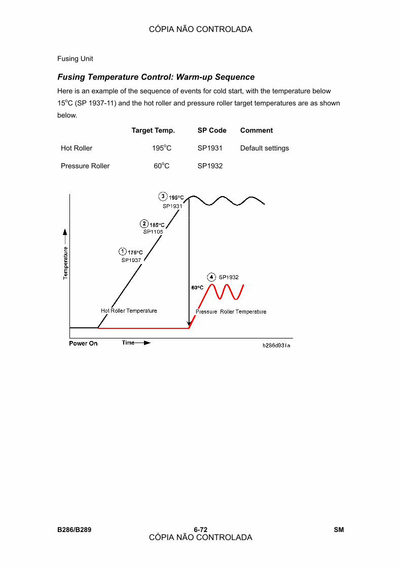
Fusing Unit
B286/B289 6-72 SM
Fusing Temperature Control: Warm-up Sequence Here is an example of the sequence of events for cold start, with the temperature below
15oC (SP 1937-11) and the hot roller and pressure roller target temperatures are as shown
below.
Target Temp. SP Code Comment
Hot Roller 195oC SP1931
Pressure Roller 60oC SP1932
Default settings
CÓPIA NÃO CONTROLADA
CÓPIA NÃO CONTROLADA
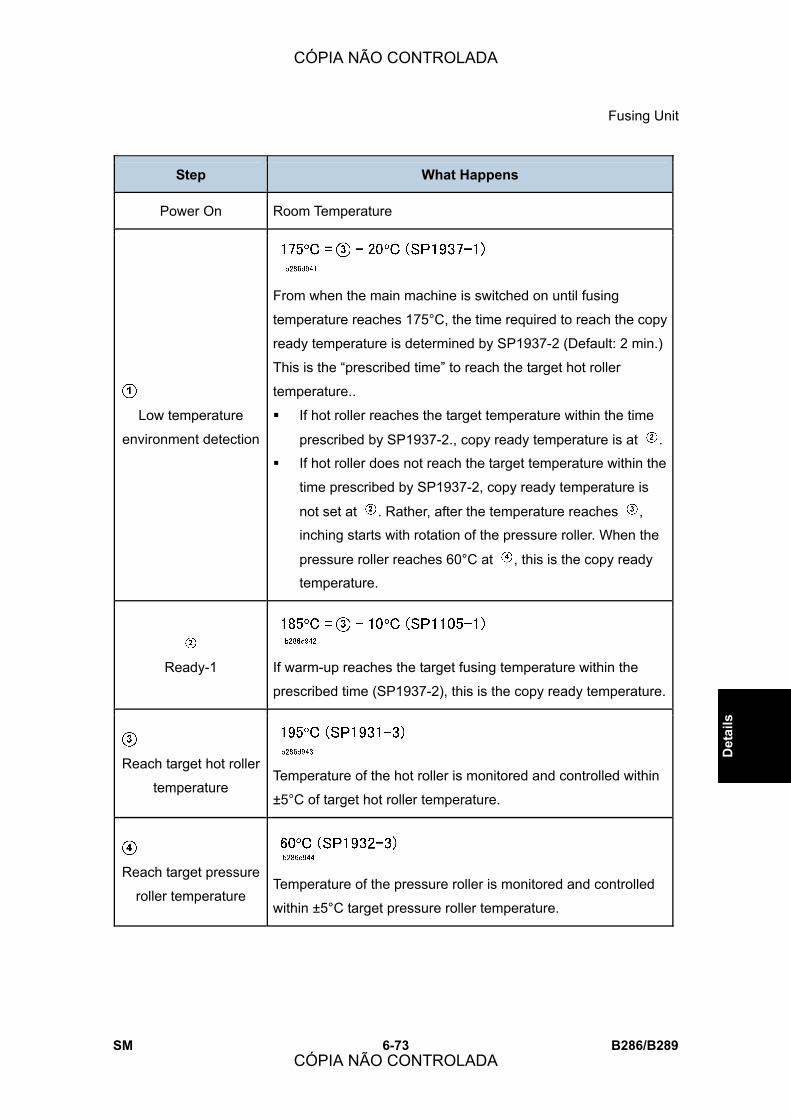
Fusing Unit
SM 6-73 B286/B289
Det
ails
Step What Happens
Power On Room Temperature
Low temperature
environment detection
From when the main machine is switched on until fusing
temperature reaches 175°C, the time required to reach the copy
ready temperature is determined by SP1937-2 (Default: 2 min.)
This is the �prescribed time� to reach the target hot roller
temperature..
! If hot roller reaches the target temperature within the time
prescribed by SP1937-2., copy ready temperature is at .
! If hot roller does not reach the target temperature within the
time prescribed by SP1937-2, copy ready temperature is
not set at . Rather, after the temperature reaches ,
inching starts with rotation of the pressure roller. When the
pressure roller reaches 60°C at , this is the copy ready
temperature.
Ready-1
If warm-up reaches the target fusing temperature within the
prescribed time (SP1937-2), this is the copy ready temperature.
Reach target hot roller
temperature
Temperature of the hot roller is monitored and controlled within
±5°C of target hot roller temperature.
Reach target pressure
roller temperature
Temperature of the pressure roller is monitored and controlled
within ±5°C target pressure roller temperature.
CÓPIA NÃO CONTROLADA
CÓPIA NÃO CONTROLADA

Fusing Unit
B286/B289 6-74 SM
Note:
If the target pressure roller temperature is set for 65°C, inching with rotation of the pressure
roller and hot roller starts, then the copy ready temperature is set when both temperatures
at and are reached.
! Inching Start Temperature = SP1937-3
! Pressure roller target temperature for inching control: SP1948
Fusing Temperature Control: Temperature Feedback During Copying This machine uses the feedback of the hot roller thermistor and two pressure roller
thermistors, one at the center and one at the end of the pressure roller, to control the fusing
temperature. The SP codes settings shown in the tables and illustrations below determine
how fusing temperature is controlled for the paper thickness modes (Mode 1 to 5) for each
type of paper.
Here is a quick summary of the SP codes that are used to maintain optimum fusing
temperature.
! These SP codes are set at the factory and normally should not require adjustment
in the field.
1931 Target Temp: Hot Roller Sets the target temperature of the hot roller.
1932 Target Temp: Press Roller Sets the target temperature of the pressure
roller
1934 Lower Limit Temp: Hot Roller
Sets the minimum difference in temperature
allowed between the actual temperature and
the target temperature of the hot roller
1935 Pressure FB Control Steps
Changes the stepped adjustments of SP1932
(Target Temp: Pressure Roller) by using the
sum of the settings of SP1932 (Target Temp:
Pressure Roller) +SP1935 (Press FB Control
Steps).
1941 Press FB Ctrl Switch by Temp
Diff
Sets the temperature differential that
determines when the machine switches to the
supplement mode for pressure roller feedback
control. (See description below.)
CÓPIA NÃO CONTROLADA
CÓPIA NÃO CONTROLADA
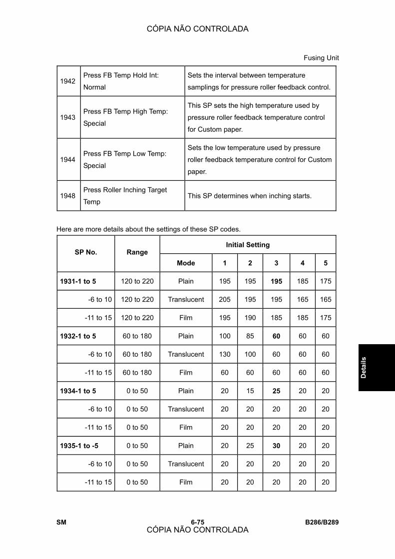
Fusing Unit
SM 6-75 B286/B289
Det
ails
1942 Press FB Temp Hold Int:
Normal
Sets the interval between temperature
samplings for pressure roller feedback control.
1943 Press FB Temp High Temp:
Special
This SP sets the high temperature used by
pressure roller feedback temperature control
for Custom paper.
1944 Press FB Temp Low Temp:
Special
Sets the low temperature used by pressure
roller feedback temperature control for Custom
paper.
1948 Press Roller Inching Target
Temp This SP determines when inching starts.
Here are more details about the settings of these SP codes.
Initial Setting SP No. Range
Mode 1 2 3 4 5
1931-1 to 5 120 to 220 Plain 195 195 195 185 175
-6 to 10 120 to 220 Translucent 205 195 195 165 165
-11 to 15 120 to 220 Film 195 190 185 185 175
1932-1 to 5 60 to 180 Plain 100 85 60 60 60
-6 to 10 60 to 180 Translucent 130 100 60 60 60
-11 to 15 60 to 180 Film 60 60 60 60 60
1934-1 to 5 0 to 50 Plain 20 15 25 20 20
-6 to 10 0 to 50 Translucent 20 20 20 20 20
-11 to 15 0 to 50 Film 20 20 20 20 20
1935-1 to -5 0 to 50 Plain 20 25 30 20 20
-6 to 10 0 to 50 Translucent 20 20 20 20 20
-11 to 15 0 to 50 Film 20 20 20 20 20
CÓPIA NÃO CONTROLADA
CÓPIA NÃO CONTROLADA
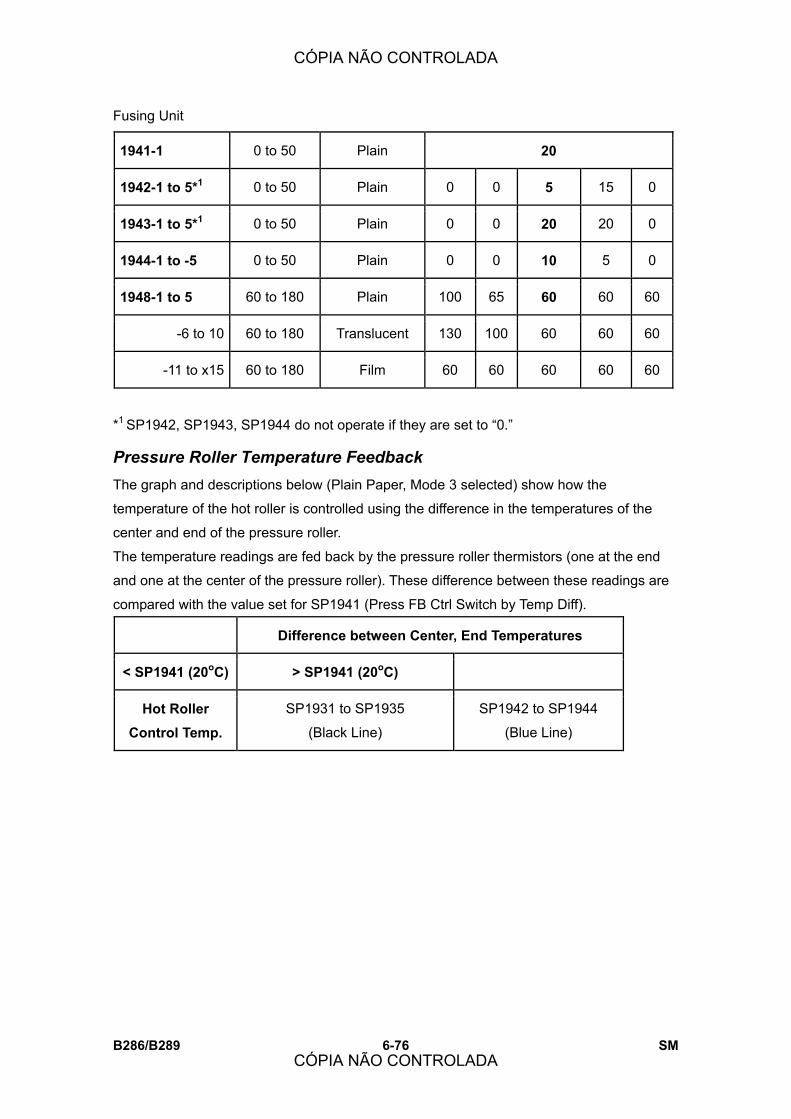
Fusing Unit
B286/B289 6-76 SM
1941-1 0 to 50 Plain 20
1942-1 to 5*1 0 to 50 Plain 0 0 5 15 0
1943-1 to 5*1 0 to 50 Plain 0 0 20 20 0
1944-1 to -5 0 to 50 Plain 0 0 10 5 0
1948-1 to 5 60 to 180 Plain 100 65 60 60 60
-6 to 10 60 to 180 Translucent 130 100 60 60 60
-11 to x15 60 to 180 Film 60 60 60 60 60
*1 SP1942, SP1943, SP1944 do not operate if they are set to �0.�
Pressure Roller Temperature Feedback The graph and descriptions below (Plain Paper, Mode 3 selected) show how the
temperature of the hot roller is controlled using the difference in the temperatures of the
center and end of the pressure roller.
The temperature readings are fed back by the pressure roller thermistors (one at the end
and one at the center of the pressure roller). These difference between these readings are
compared with the value set for SP1941 (Press FB Ctrl Switch by Temp Diff).
Difference between Center, End Temperatures
< SP1941 (20oC) > SP1941 (20oC)
Hot Roller Control Temp.
SP1931 to SP1935
(Black Line)
SP1942 to SP1944
(Blue Line)
CÓPIA NÃO CONTROLADA
CÓPIA NÃO CONTROLADA
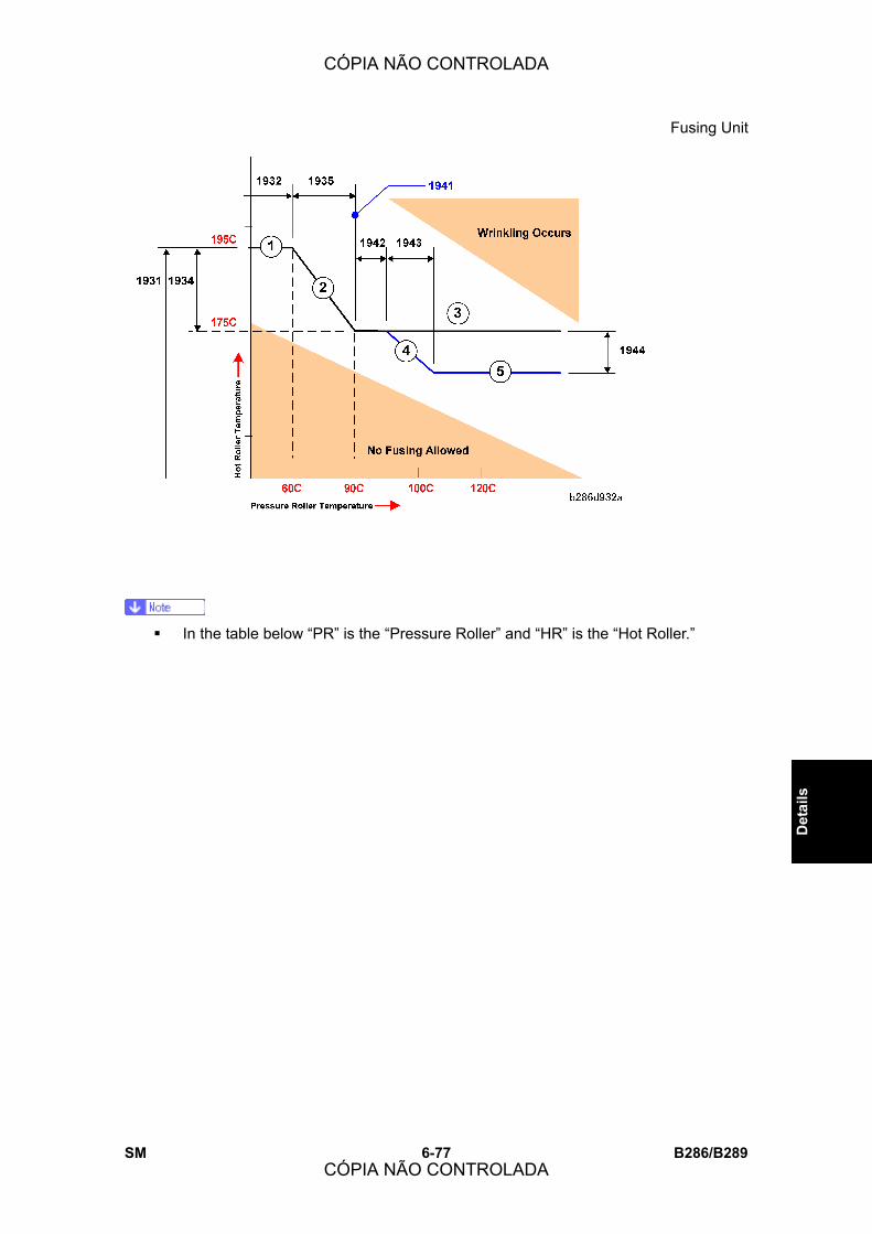
Fusing Unit
SM 6-77 B286/B289
Det
ails
! In the table below �PR� is the �Pressure Roller� and �HR� is the �Hot Roller.�
CÓPIA NÃO CONTROLADA
CÓPIA NÃO CONTROLADA

Fusing Unit
B286/B289 6-78 SM
PR
(°C) HR
(°C) Controlling SP Codes
60 195 HR:SP1931
PR:SP1932
61-90 194-175 < SP1941(20°C)
> 96 175
HR:SP1931-SP1934
PR:SP1932+SP1935
< 60 195 HR:SP1931
PR:SP1932
61-90 194-175 HR:SP1931-SP1934
PR:SP1932+SP1935
91-95 175
PR:SP1942 (91°C to 95°C)
HR:SP1931-SP1934
PR:SP1932+SP1935
96-120 174-165
> SP1941 (20°C)
< 121 165
HR:SP1931+(SP1934+SP1944)
PR:SP1932+(SP1935+SP1943)
CÓPIA NÃO CONTROLADA
CÓPIA NÃO CONTROLADA
Fusing Unit
SM 6-79 B286/B289
Det
ails
Fusing Temperature Control: Inching The default setting for this machine is for inching control to always remain on.
! This inching control on/off setting (controlled by SP9952) should never be
switched off.
During inching control:
! When the temperature of the hot roller falls to 20°C (SP1937-3) below its target
temperature, the fusing motor switches on and idling starts.
! When the pressure roller reaches its target temperature, the fusing motor switches off
and idling stops.
! The target temperature of the pressure roller is controlled by the settings of
SP1932 (Target Temperature: Pressure Roller) for each paper type.
Fusing Temperature Control: CPM Down During a long copy job on narrow width paper, the difference in the temperatures between
the center and end of the pressure roller increases. The temperature at the center
decreases and the temperatures at the ends increase. In order to prevent this, CPM down
control automatically adjusts the timing of paper feed. This increases the length of the
interval between sheets in the paper path.
A longer interval between sheets creates a short delay between feeds to the fusing unit.
This extra time allows slightly more time so that the temperature of the hot roller and
pressure roller can rise.
! The operation of CPM down is controlled by SP1940-1 (CPM Down Setting). This SP
code should remain on.
! For more about adjusting these settings see the description of SP1940 in �Service
Tables.�
CÓPIA NÃO CONTROLADA
CÓPIA NÃO CONTROLADA

Fusing Unit
B286/B289 6-80 SM
6.9.6 HOT ROLLER CLEANING
The cleaning roller [B] (parallel to the hot roller) always touches the hot roller [A] with a low
pressure. The cleaning roller has a layer of material that is soaked with silicone oil. Each
time the fusing motor switches on, it reverses for 400 ms (at line speed 30 mm/s) to clean
the hot roller.
CÓPIA NÃO CONTROLADA
CÓPIA NÃO CONTROLADA

Fusing Unit
SM 6-81 B286/B289
Det
ails
6.9.7 FUSING UNIT DRIVE MECHANISM
The fusing motor [A] (a stepper motor) controls the gears and timing belt [B] that turn the
hot roller [C]
The pressure of the hot roller against the pressure roller [D] and cleaning roller [E] turns
these rollers in the opposite direction.
An idle gear [F] turns the gears and timing belt [G]. These gears and belts turn the fusing
exit roller [H] and upper exit rollers [I] in the same direction as the hot roller.
The speed of the fusing motor is controlled by:
! The paper feed source set by the user (manual feed table, roll feeder paper, and
cassette).
! The type of paper set for the paper feed source: plain (not displayed), recycled,
translucent, or film, (This is done with the User Tool: System Settings > Paper Type
Settings > Paper Type).
! The width of the paper in the feed source that is used. (The width in each feed source
is set with the User Tool 1 System Setting > 1 General Features > Tray Paper Size.
The feed source for the job is set at the operation panel.)
CÓPIA NÃO CONTROLADA
CÓPIA NÃO CONTROLADA
Fusing Unit
B286/B289 6-82 SM
6.9.8 WRINKLE PREVENTION
Motor Speed Control During normal operation, the hot roller [A] (controlled by the fusing motor) is slightly faster
than the registration rollers [B] (controlled by the main motor).
This stretches the paper between the registration rollers and the fusing unit to keep the
paper from wrinkling inside the fusing unit.
Inching Control This machine also has an inching control feature that controls the temperature of the
pressure roller to prevent wrinkling. (See Section 6.9.5 �Temperature Control.�)
CÓPIA NÃO CONTROLADA
CÓPIA NÃO CONTROLADA

Paper Exit
SM 6-83 B286/B289
Det
ails
6.10 PAPER EXIT
6.10.1 OVERVIEW
The fusing exit rollers [5] send the paper to the paper junction gate [3].
Upper Exit When the paper junction gate [3] is closed:
! The gate sends the paper to the upper exit rollers [2].
! The upper exit rollers feed the paper out of the upper paper exit [1] to a wire guide on
top of the machine. The user can remove this wire guide.
! The wire guide holds the paper against the rear side of the original output tray.
CÓPIA NÃO CONTROLADA
CÓPIA NÃO CONTROLADA

Paper Exit
B286/B289 6-84 SM
Rear Exit When the paper junction gate is open:
! The gate sends the paper to the rear paper exit [4].
! The paper moves past mylars attached on the rear of the machine.
! The paper falls into the lower output tray [7] and then stops in the lower output stacker
[8].
Jam Detection The exit sensor [6] detects paper jams.
6.10.2 SWITCHING THE PAPER EXIT
Upper Exit When the �Upper� (Copy Output Location) indicator on the operation panel is ON and the
copy exit lever [1] is UP:
! The paper junction gate solenoid [2] stays off.
! The fusing exit rollers [3] send the paper to the paper junction gate [4].
! The closed junction gate sends the paper to the upper exit rollers [5].
! The upper exit rollers feed the paper out of the upper exit [6].
CÓPIA NÃO CONTROLADA
CÓPIA NÃO CONTROLADA

Paper Exit
SM 6-85 B286/B289
Det
ails
Rear Exit
Copy Exit Lever Up (�Upper� and �Lower� Selection Allowed) With the copy exit lever up, the operator has the option of selecting �Upper� or �Lower�
under �Copy Output Location� on the operation panel display. (�Upper� is the default
selection.)
With �Upper� selected, the copy exits to the top of the main machine.
If the operator selects �Lower� with the copy exit lever [1] up:
! The paper exit selection sensor [2] detects the lever in the up position.
! The solenoid [3] switches on and opens the paper junction gate [4].
! The fusing exit rollers [5] send the paper past the paper junction gate to the rear paper
exit [6].
CÓPIA NÃO CONTROLADA
CÓPIA NÃO CONTROLADA

Paper Exit
B286/B289 6-86 SM
Copy Exit Lever Down (�Upper� Selection Not Allowed) ! The paper exit selection sensor [3] detects the lever in the �Lower� (down) position.
! The operator must select �Lower� under �Copy Output Location� on the operation panel
display. If the operator selects �Upper� with the lever down, the machine will display a
message:
Cannot output to the selected location
Switch copy exit switching lever or paper output location
! After the operator selects �Lower�, the operation sequence is the same as that
described above (with the lever up and �Lower� selected).
Keep the copy exit selection lever in the vertical position for normal operation. This allows
the operator to select the copy output destination on the operation panel.
6.10.3 PAPER EXIT DRIVE
See Section 6.9.7 �Fusing Unit Drive Mechanism.�
CÓPIA NÃO CONTROLADA
CÓPIA NÃO CONTROLADA
Electrical Components
SM 6-87 B286/B289
Det
ails
6.11 ELECTRICAL COMPONENTS
6.11.1 OVERVIEW
Overall System The illustration below shows the configuration of the system components.
⇒
Rev. 10/2007
CÓPIA NÃO CONTROLADA
CÓPIA NÃO CONTROLADA

Electrical Components
B286/B289 6-88 SM
[A] Printer components:
1. Motors 4. Thermistors
2. Sensors 5. Solenoids: Separation, Paper Exit
3. Fan Motors 6. Clutches:
Here is a brief description of functions of the important boards:
MCU (Main Control Unit). This is the engine control board. The MCU manages:
! Base engine control, scanning control, image processing control, image writing control.
! Basic I/O function control for the power packs, motors, sensors, solenoids, clutches,
and fusing.
! Power supply to scanner components (sensors, motors).
SIB (Scanner Interface Board). Controls the operation of the CIS elements (x5) and does
the sub scan correction to compensate for their staggered arrangement. Also manages the
A/D conversion of the scanned image data.
IPU (Image Processing Unit). Provided with five RI1001A_BGA components that do
every type of processing of the image data received from the SIB. LUPUS contains the
Rapi I/F functions. Also manages sending and receiving image data between itself and the
GW controller board.
MB (Mother Board). Provides important relay functions 1) for the Rapi Bus I/F between the
IPU, GW controller, file format converter, and VLB, and 2) for machine power supply.
VDB (Video Drive Board). Controls operation of the LPH (LED Print Head), including the
conversion of video sent to the LPH.
GW controller (Type-Bz2). Performs overall control of all multi-function peripheral (MFP)
devices.
CÓPIA NÃO CONTROLADA
CÓPIA NÃO CONTROLADA

Electrical Components
SM 6-89 B286/B289
Det
ails
IPU Board Details
Image data scanned by the CIS elements is converted from analog to digital data by the
SIB and then sent to the IPU for processing.
CÓPIA NÃO CONTROLADA
CÓPIA NÃO CONTROLADA
Electrical Components
B286/B289 6-90 SM
6.11.2 DESCRIPTION OF ELECTRICAL COMPONENTS
NUMBER NAME DESCRIPTION
CIS
CIS1 - 5 CIS 1 - 5 (Contact Image
Sensor)
Transfer the image signals from the CIS LEDs
to the SIB.
Lamp
L1 Fusing Lamp One fusing lamp (1100 W) in the hot roller.
LPH
LPH1-3 LPH1-3 (LED Print Head) Each section writes a part of the image on the
PCB drum. The VDB controls the LPH units.
Magnetic Clutches
MC1 Cassette Feed Clutch
This transfers power from the cassette feed
motor to the feed and grip rollers in the
cassette.
MC2 Paper Registration Clutch
This controls the registration roller. It switches
off for a short time to stop the registration roller
to correct skew in the paper feed path.
MC3 Roll Feed Clutch 1 This transfers power from the roll feed motor
to roll 1 in the roll feeder.
MC4 Roll Feed Clutch 2 This transfers power from the roll feed motor
to roll 2 in the roll feeder.
MC5 Toner Supply Clutch This controls the toner supply mechanism.
Motors
M1 Cassette Feed Motor This stepper motor controls the paper feed
roller in the paper cassette.
M2 Cooling Fan Motor This is an exhaust fan for the area around the
drum.
CÓPIA NÃO CONTROLADA
CÓPIA NÃO CONTROLADA

Electrical Components
SM 6-91 B286/B289
Det
ails
NUMBER NAME DESCRIPTION
M3 Cutter Motor This controls the cutter in the roll feeder.
M4 Drum Motor This controls the OPC drum.
M5 Fusing Motor This controls the hot roller, fusing exit rollers,
and upper exit rollers.
M6 Main Motor
This controls the registration roller,
development unit, and the agitator in the toner
cartridge.
M7 PCB Cooling Fan Motor 1 Cools the IPU, MCU and controller board.
M8 PCB Cooling Fan Motor 2 Cools the IPU, MCU and controller board.
M9 Roll Feed Motor This controls the feed rollers for roll 1 and roll
2 in the roll feeder.
M10 Scanner Motor This controls the original feed rollers and
original exit rollers.
M11 Used Toner Bottle Motor This controls the mechanism that keeps the
level of used toner in the bottle flat.
M12 Wire Cleaner Motor This moves the corona wire cleaner to the left
and right to clean the charge corona wire.
PCBs
PCB1 IPU (Image Processing
Unit)
This processes image data from the CIS
(Contact Image Sensor), and sends it to the
VDB (Video Drive Board) and LPH (LED Print
Heads). The IPU also controls the HDD unit
and the PC interfaces.
PCB2 MCU (Main Control Unit)
This is the machine�s main board. It contains
the SCU (Scanner Control Unit) and ECU
(Engine Control Unit). These units control all
parts of the machine, and this includes the
print engine, scanner, and image processing.
CÓPIA NÃO CONTROLADA
CÓPIA NÃO CONTROLADA

Electrical Components
B286/B289 6-92 SM
NUMBER NAME DESCRIPTION
PCB3 Operation Panel
This contains the operation keys, touch-panel
LCD, and the LEDs. It is controlled by the
MCU.
PCB4 PSU (Power Supply Unit) This supplies dc power for the machine,
heaters, and dehumidifiers in the roll feeder.
PCB5 RFDB (Roll Feed Drive
Board)
This is attached to the optional roll feeder. It
controls the components of the roll feeder
(motor, clutches, sensors, and switches).
PCB6 SFDB (Sheet Feed Drive
Board)
This is attached to the optional paper cassette.
It controls the components of the paper
cassette (motor, clutches, sensors, and
switches).
PCB7 SIB (Scanner Interface
Board)
This controls the scanner, and is an interface
board for the IPU and MCU.
PCB8 Mother Board
Interfaces with the controller, IPU, and
optional devices such as interface board for
the printer controller.
PCB9 VDB (Video Drive Board) This controls the image signals that are sent to
the LPH (LED Print Head).
PCB10 Controller Board
Controls the memory and all peripheral
devices. The GW architecture allows the
board to control all applications (copying,
printing, and scanning).
PCB11 Interface Board
Option. This relay board must be installed with
the external printer controller for interface
between the server PC and the copier.
PCB12 File Format Converter
(MLB) Option.
CÓPIA NÃO CONTROLADA
CÓPIA NÃO CONTROLADA

Electrical Components
SM 6-93 B286/B289
Det
ails
NUMBER NAME DESCRIPTION
Power Packs
PP1 CGB Power Pack
High voltage power supply for the charge
corona wire ©, development bias (B), and
charge corona grid (G).
PP2 T&S Power Pack
High voltage power supply for the transfer
corona wire (T) and the separation corona
wire (S) in the T&S (Transfer and Separation)
unit.
QL
QL1 - 3
Quenching Lamp 1 � 3
(1: Left, 2: Center, 3:
Right)
This removes remaining electrical charge on
the drum immediately after cleaning.
Sensors
S1 Cassette End Sensor This sensor is above the paper cassette. It
detects paper end after the last sheet feeds.
S2 Cassette Set Sensor This detects when the cassette is set and
locked in its place.
S3 Exit Cover Sensor This detects if the exit cover on the rear of the
machine is open or closed.
S4 Fusing Exit Sensor
This sensor is in front of the fusing exit rollers.
It switches on when the leading edge of the
copy leaves the fusing unit.
S5 ID Sensor
The machine uses this sensor to control toner
supply, toner near-end, and toner end. There
is no toner density sensor in this machine.
S6 Original Exit Sensor This detects the original when it feeds out of
the scanner.
CÓPIA NÃO CONTROLADA
CÓPIA NÃO CONTROLADA
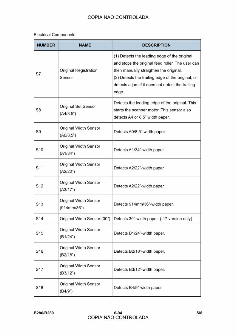
Electrical Components
B286/B289 6-94 SM
NUMBER NAME DESCRIPTION
S7 Original Registration
Sensor
(1) Detects the leading edge of the original
and stops the original feed roller. The user can
then manually straighten the original.
(2) Detects the trailing edge of the original, or
detects a jam if it does not detect the trailing
edge.
S8 Original Set Sensor
(A4/8.5�)
Detects the leading edge of the original. This
starts the scanner motor. This sensor also
detects A4 or 8.5� width paper.
S9 Original Width Sensor
(A0/8.5�) Detects A0/8.5�-width paper.
S10 Original Width Sensor
(A1/34�) Detects A1/34�-width paper.
S11 Original Width Sensor
(A2/22�) Detects A2/22�-width paper.
S12 Original Width Sensor
(A3/17�) Detects A2/22�-width paper.
S13 Original Width Sensor
(914mm/36�) Detects 914mm/36�-width paper.
S14 Original Width Sensor (30�) Detects 30�-width paper. (-17 version only)
S15 Original Width Sensor
(B1/24�) Detects B1/24�-width paper.
S16 Original Width Sensor
(B2/18�) Detects B2/18�-width paper.
S17 Original Width Sensor
(B3/12�) Detects B3/12�-width paper.
S18 Original Width Sensor
(B4/9�) Detects B4/9�-width paper.
CÓPIA NÃO CONTROLADA
CÓPIA NÃO CONTROLADA
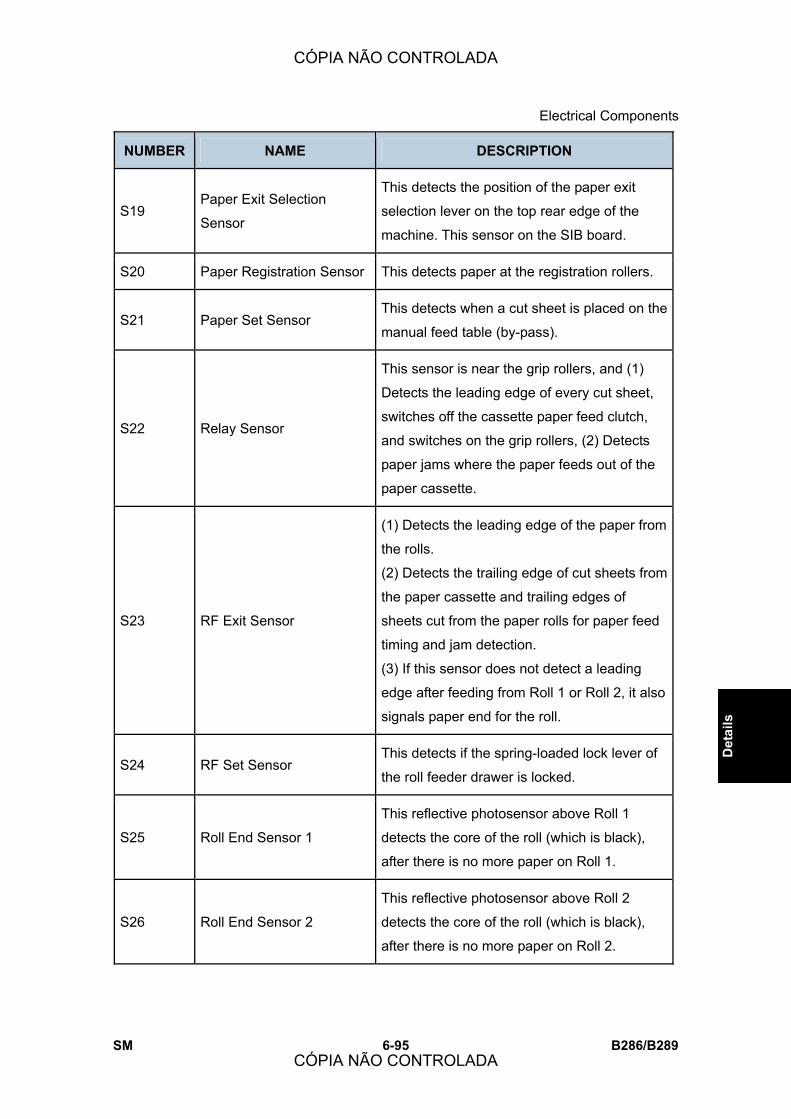
Electrical Components
SM 6-95 B286/B289
Det
ails
NUMBER NAME DESCRIPTION
S19 Paper Exit Selection
Sensor
This detects the position of the paper exit
selection lever on the top rear edge of the
machine. This sensor on the SIB board.
S20 Paper Registration Sensor This detects paper at the registration rollers.
S21 Paper Set Sensor This detects when a cut sheet is placed on the
manual feed table (by-pass).
S22 Relay Sensor
This sensor is near the grip rollers, and (1)
Detects the leading edge of every cut sheet,
switches off the cassette paper feed clutch,
and switches on the grip rollers, (2) Detects
paper jams where the paper feeds out of the
paper cassette.
S23 RF Exit Sensor
(1) Detects the leading edge of the paper from
the rolls.
(2) Detects the trailing edge of cut sheets from
the paper cassette and trailing edges of
sheets cut from the paper rolls for paper feed
timing and jam detection.
(3) If this sensor does not detect a leading
edge after feeding from Roll 1 or Roll 2, it also
signals paper end for the roll.
S24 RF Set Sensor This detects if the spring-loaded lock lever of
the roll feeder drawer is locked.
S25 Roll End Sensor 1
This reflective photosensor above Roll 1
detects the core of the roll (which is black),
after there is no more paper on Roll 1.
S26 Roll End Sensor 2
This reflective photosensor above Roll 2
detects the core of the roll (which is black),
after there is no more paper on Roll 2.
CÓPIA NÃO CONTROLADA
CÓPIA NÃO CONTROLADA
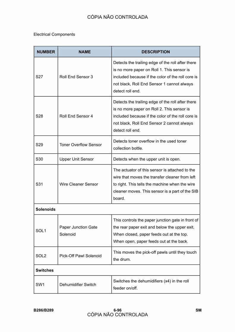
Electrical Components
B286/B289 6-96 SM
NUMBER NAME DESCRIPTION
S27 Roll End Sensor 3
Detects the trailing edge of the roll after there
is no more paper on Roll 1. This sensor is
included because if the color of the roll core is
not black, Roll End Sensor 1 cannot always
detect roll end.
S28 Roll End Sensor 4
Detects the trailing edge of the roll after there
is no more paper on Roll 2. This sensor is
included because if the color of the roll core is
not black, Roll End Sensor 2 cannot always
detect roll end.
S29 Toner Overflow Sensor Detects toner overflow in the used toner
collection bottle.
S30 Upper Unit Sensor Detects when the upper unit is open.
S31 Wire Cleaner Sensor
The actuator of this sensor is attached to the
wire that moves the transfer cleaner from left
to right. This tells the machine when the wire
cleaner moves. This sensor is a part of the SIB
board.
Solenoids
SOL1 Paper Junction Gate
Solenoid
This controls the paper junction gate in front of
the rear paper exit and below the upper exit.
When closed, paper feeds out at the top.
When open, paper feeds out at the back.
SOL2 Pick-Off Pawl Solenoid This moves the pick-off pawls until they touch
the drum.
Switches
SW1 Dehumidifier Switch Switches the dehumidifiers (x4) in the roll
feeder on/off.
CÓPIA NÃO CONTROLADA
CÓPIA NÃO CONTROLADA
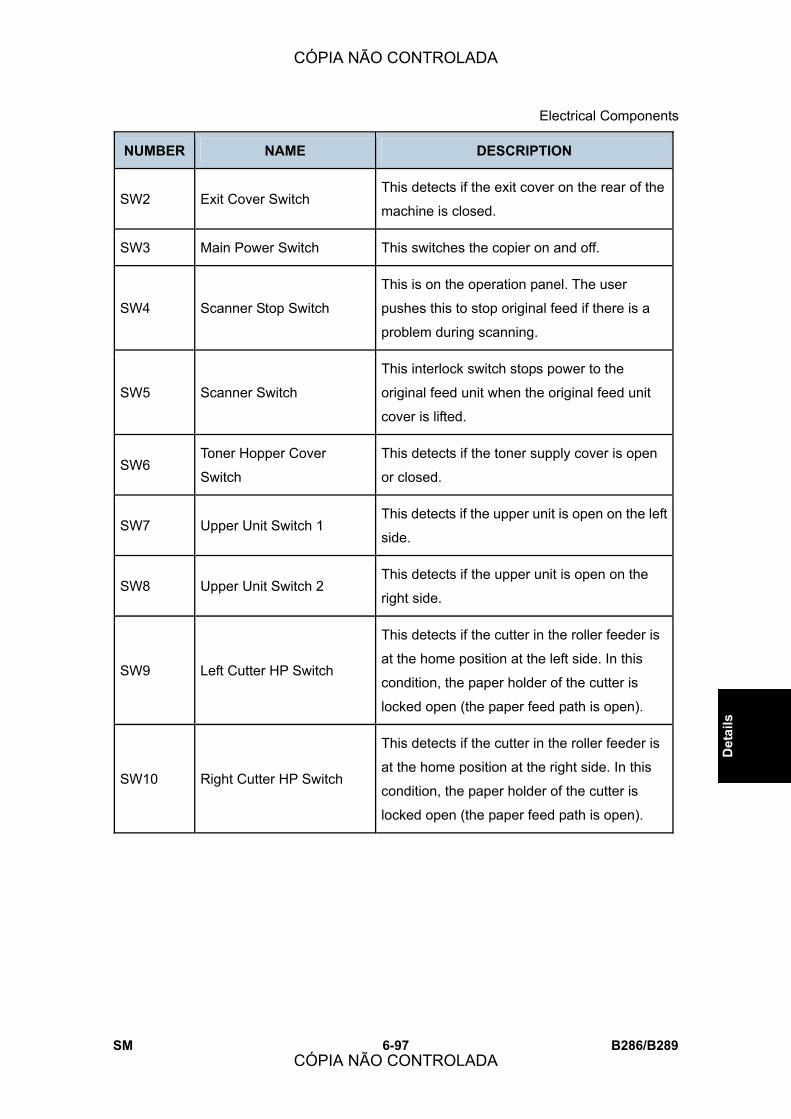
Electrical Components
SM 6-97 B286/B289
Det
ails
NUMBER NAME DESCRIPTION
SW2 Exit Cover Switch This detects if the exit cover on the rear of the
machine is closed.
SW3 Main Power Switch This switches the copier on and off.
SW4 Scanner Stop Switch
This is on the operation panel. The user
pushes this to stop original feed if there is a
problem during scanning.
SW5 Scanner Switch
This interlock switch stops power to the
original feed unit when the original feed unit
cover is lifted.
SW6 Toner Hopper Cover
Switch
This detects if the toner supply cover is open
or closed.
SW7 Upper Unit Switch 1 This detects if the upper unit is open on the left
side.
SW8 Upper Unit Switch 2 This detects if the upper unit is open on the
right side.
SW9 Left Cutter HP Switch
This detects if the cutter in the roller feeder is
at the home position at the left side. In this
condition, the paper holder of the cutter is
locked open (the paper feed path is open).
SW10 Right Cutter HP Switch
This detects if the cutter in the roller feeder is
at the home position at the right side. In this
condition, the paper holder of the cutter is
locked open (the paper feed path is open).
CÓPIA NÃO CONTROLADA
CÓPIA NÃO CONTROLADA
Electrical Components
B286/B289 6-98 SM
NUMBER NAME DESCRIPTION
SW11 Exit Unit Switch
Detects whether the fusing unit cover is open
or closed. SC559 is issued after 3 consecutive
jams occur in the fusing unit.
Note: SC559 is not issued unless SP1159 is
switched on (Default: �0� off).
The fusing unit cover must always be opened
and closed after this SC occurs to restore the
machine to full operation. This ensures that
the operator has opened and closed the cover
to check for paper and/or paper scraps around
the hot roller. Loose paper around the hot
roller is a fire hazard.
Others
CO1 Recycle Counter
A mechanical counter that measures the total
length in meters of paper that the machine
feeds. It starts from the first copy.
H1 Dehumidifier 1
(Front/Right)
H2 Dehumidifier 2 (Front/Left)
H3 Dehumidifier 3 (Rear/Right)
H4 Dehumidifier 4 (Rear/Left)
One of four dehumidifiers that keeps the roll
feeder drawer free of moisture.
H5 Anti-Condensation Heater
(Left)
H6 Anti-Condensation Heater
(Right)
These are below the OPC drum. They keep
the copier free of moisture, which could cause
problems with paper feed and fusing.
HDD1 HDD
TH1 Hot Roller Thermistor The CPU uses this thermistor to monitor the
temperature of the hot roller.
CÓPIA NÃO CONTROLADA
CÓPIA NÃO CONTROLADA

Electrical Components
SM 6-99 B286/B289
Det
ails
NUMBER NAME DESCRIPTION
TH2 Pressure Roller Thermistor
1 (Edge)
TH3
Pressure Roller Thermistor
2
(Center)
The CPU uses this thermistor to monitor the
temperature of the pressure roller.
TS1 Thermostat 1 (Center)
199°C. This safety device prevents
overheating if the temperature control circuit
fails.
TS2 Thermostat 2 (End)
200°C. This safety device prevents
overheating if the temperature control circuit
fails.
CB1 Circuit Breaker
Breaks the main power supply to the machine
if there is an overload or short circuit. Located
on the back of the machine, this switch is set
manually. This breaker switch must be at the
down position for the machine to operate. For
more, see section 1.2.3 �Main Machine Final
Installation.�
CÓPIA NÃO CONTROLADA
CÓPIA NÃO CONTROLADA
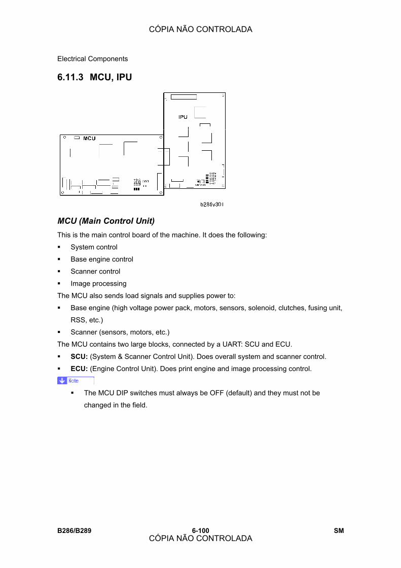
Electrical Components
B286/B289 6-100 SM
6.11.3 MCU, IPU
MCU (Main Control Unit) This is the main control board of the machine. It does the following:
! System control
! Base engine control
! Scanner control
! Image processing
The MCU also sends load signals and supplies power to:
! Base engine (high voltage power pack, motors, sensors, solenoid, clutches, fusing unit,
RSS, etc.)
! Scanner (sensors, motors, etc.)
The MCU contains two large blocks, connected by a UART: SCU and ECU.
! SCU: (System & Scanner Control Unit). Does overall system and scanner control.
! ECU: (Engine Control Unit). Does print engine and image processing control.
! The MCU DIP switches must always be OFF (default) and they must not be
changed in the field.
CÓPIA NÃO CONTROLADA
CÓPIA NÃO CONTROLADA
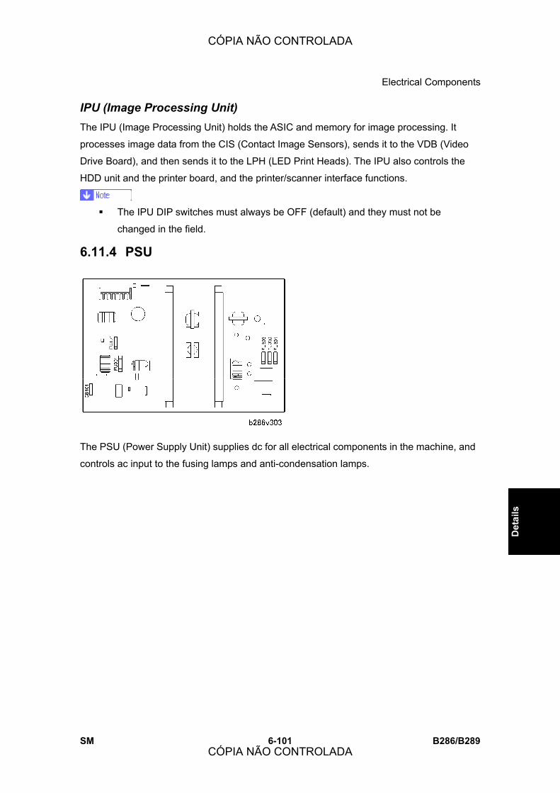
Electrical Components
SM 6-101 B286/B289
Det
ails
IPU (Image Processing Unit) The IPU (Image Processing Unit) holds the ASIC and memory for image processing. It
processes image data from the CIS (Contact Image Sensors), sends it to the VDB (Video
Drive Board), and then sends it to the LPH (LED Print Heads). The IPU also controls the
HDD unit and the printer board, and the printer/scanner interface functions.
! The IPU DIP switches must always be OFF (default) and they must not be
changed in the field.
6.11.4 PSU
The PSU (Power Supply Unit) supplies dc for all electrical components in the machine, and
controls ac input to the fusing lamps and anti-condensation lamps.
CÓPIA NÃO CONTROLADA
CÓPIA NÃO CONTROLADA
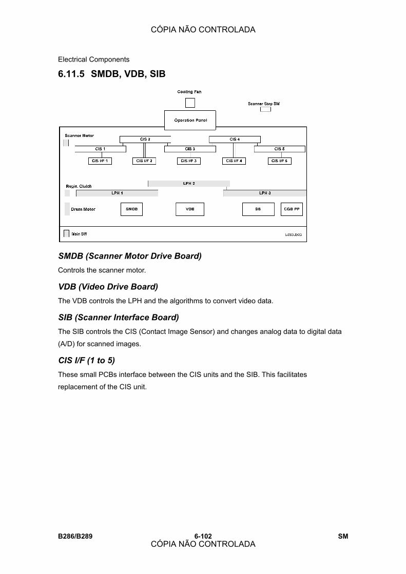
Electrical Components
B286/B289 6-102 SM
6.11.5 SMDB, VDB, SIB
SMDB (Scanner Motor Drive Board) Controls the scanner motor.
VDB (Video Drive Board) The VDB controls the LPH and the algorithms to convert video data.
SIB (Scanner Interface Board) The SIB controls the CIS (Contact Image Sensor) and changes analog data to digital data
(A/D) for scanned images.
CIS I/F (1 to 5) These small PCBs interface between the CIS units and the SIB. This facilitates
replacement of the CIS unit.
CÓPIA NÃO CONTROLADA
CÓPIA NÃO CONTROLADA

Electrical Components
SM 6-103 B286/B289
Det
ails
6.11.6 RFDB, SFDB
The RFDB and SFDB are on the bottom plate of the drawer in the optional roll sheet feeder.
RFDB (Roll Feed Drive Board) The RFDB, on the floor panel of the roll feeder, controls the motors, solenoids, and
clutches for the two paper rolls in the roll sheet feeder.
SFDB (Sheet Feed Drive Board) The SFDB, on the left side of the paper cassette unit, controls the paper feed mechanisms
for the optional paper cassette.
CÓPIA NÃO CONTROLADA
CÓPIA NÃO CONTROLADA
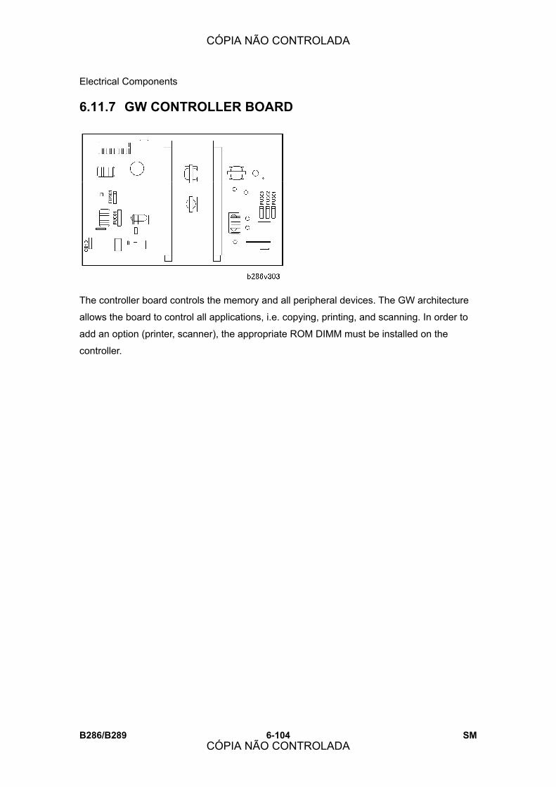
Electrical Components
B286/B289 6-104 SM
6.11.7 GW CONTROLLER BOARD
The controller board controls the memory and all peripheral devices. The GW architecture
allows the board to control all applications, i.e. copying, printing, and scanning. In order to
add an option (printer, scanner), the appropriate ROM DIMM must be installed on the
controller.
CÓPIA NÃO CONTROLADA
CÓPIA NÃO CONTROLADA
SPECIFICATIONS
CÓPIA NÃO CONTROLADA
CÓPIA NÃO CONTROLADA

CÓPIA NÃO CONTROLADA
CÓPIA NÃO CONTROLADA

Main Machine (B286/B289)
SM 7-1 B286/B289
Spec
ifica
tions
7. SPECIFICATIONS
7.1 MAIN MACHINE (B286/B289)
Configuration: Desktop
Copy Process: Dry electrostatic transfer system
Originals: Sheet
Original Image Size (W x L): Maximum: 914 x 15,000 mm (36” x 590”)
Minimum: 210 x 210 mm (8.5” x 8.5”)
Maximum length copying (15 m) is limited to
wide paper.
Copies at maximum length must be done one at
a time (multiple copies are not allowed).
Max Original Width: 960 mm (37.7”)
Original Weight
18 ∼ 135 g/m²
35 μm ∼ 1.0 mm
Note: Less than 70 μm must be used with carrier
sheet.
Copy Paper Size (W x L):
Maximum:
Manual feed: 914 x 2,000 mm (36” x 78”)
Roll Feed: 914 x 15,000 mm (36” x 590”)
Paper Cassette: 297 x 420mm (12” x 18”)
Minimum: Manual Feed: 210 x 257 mm (8½” x 10”)
Roll Feed: 210 x 280 mm (8½” x 11”)
Paper Cassette: 210 x 297 mm (8½” x 11”)
Copy Paper Weight
52.3 ∼ 110 g/m² (13.9 ∼ 29.3 lb)
68 ∼ 148 μm (Plain paper, Translucent)
3 ∼ 4 mils (Film)
Copying Speed (cpm: B286: 2 cpm (A0/E SEF), 4 cpm (A1/D LEF)
⇒
Rev. 10/2007
CÓPIA NÃO CONTROLADA
CÓPIA NÃO CONTROLADA
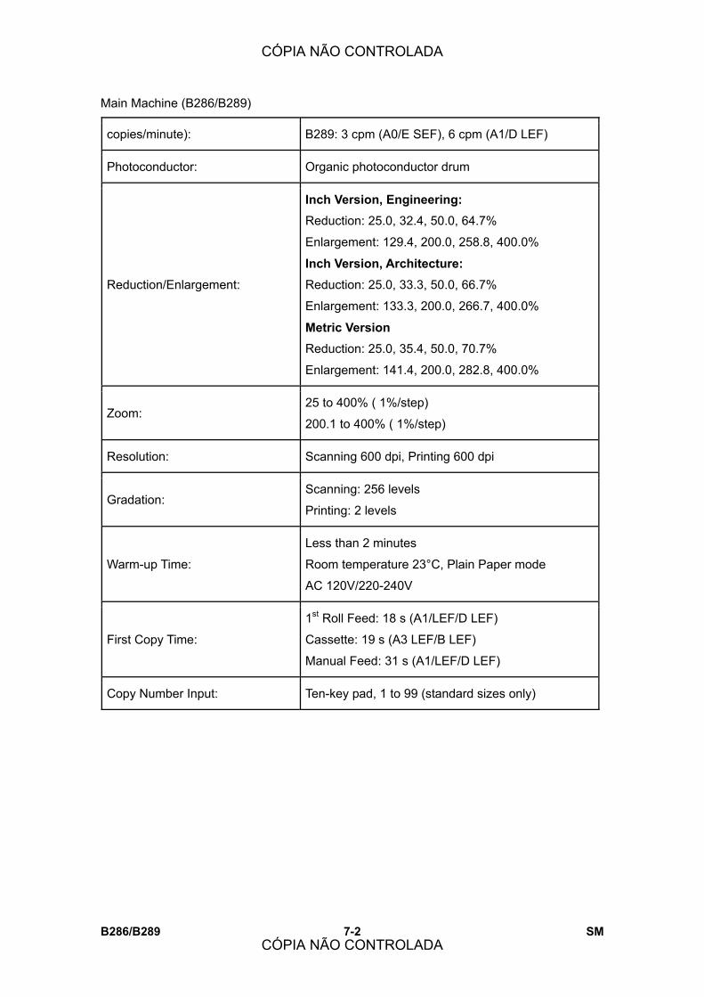
Main Machine (B286/B289)
B286/B289 7-2 SM
copies/minute): B289: 3 cpm (A0/E SEF), 6 cpm (A1/D LEF)
Photoconductor: Organic photoconductor drum
Reduction/Enlargement:
Inch Version, Engineering: Reduction: 25.0, 32.4, 50.0, 64.7%
Enlargement: 129.4, 200.0, 258.8, 400.0%
Inch Version, Architecture: Reduction: 25.0, 33.3, 50.0, 66.7%
Enlargement: 133.3, 200.0, 266.7, 400.0%
Metric Version
Reduction: 25.0, 35.4, 50.0, 70.7%
Enlargement: 141.4, 200.0, 282.8, 400.0%
Zoom: 25 to 400% ( 1%/step)
200.1 to 400% ( 1%/step)
Resolution: Scanning 600 dpi, Printing 600 dpi
Gradation: Scanning: 256 levels
Printing: 2 levels
Warm-up Time:
Less than 2 minutes
Room temperature 23°C, Plain Paper mode
AC 120V/220-240V
First Copy Time:
1st Roll Feed: 18 s (A1/LEF/D LEF)
Cassette: 19 s (A3 LEF/B LEF)
Manual Feed: 31 s (A1/LEF/D LEF)
Copy Number Input: Ten-key pad, 1 to 99 (standard sizes only)
CÓPIA NÃO CONTROLADA
CÓPIA NÃO CONTROLADA

Main Machine (B286/B289)
SM 7-3 B286/B289
Spec
ifica
tions
Copy Paper Capacity:
Bypass Feed: 1 sheet
Roll Feed: Max. Diameter: 175 mm (6.9�)
Max. Length: 150 m (16.4 yd)
Roll Core Diameter: 76.4 ±0.25 mm (about 3�)
Paper Cassette: 250 sheets
Output Tray Capacity:
Upper Output Stocker Plain paper: 50 sheets (maximum A1/D LEF)
Translucent: 10 sheets (maximum A1/D LEF)
Roll Feeder or Table
Plain paper: 40 sheets (A1/D or A0/E)
Translucent: 1 sheet
Original Stacker 1 original
Memory Capacity: DDR-DIMM: 1 GB (512 MB x 2)
HDD: More than 80
Toner Replenishment: Cartridge exchange (800 g/cartridge)
Toner Yield: 2,200 copies
(A1 LEF, 6% full black, 1 to 99 copying, Text mode)
Power Source:
-17 Version: AC 120V, 60 Hz, 15 A or more
-21, -27 Version: AC 220-240 V, 50/60 Hz, 10 A or
more
CÓPIA NÃO CONTROLADA
CÓPIA NÃO CONTROLADA

Main Machine (B286/B289)
B286/B289 7-4 SM
AC120V Version
B286 B289
Warm-up 1.4 kW
Ready*2 0.090 kW
During Copying 0.94 kW 0.96 kW
Maximum 1.5 kW
AC220-240V Version
B286 B289
Warm-up 1.4 kW
Ready*2 0.110 kW
During Copying 0.92 kW 0.94 kW
Power Consumption*1
Maximum 1.5 kW
*¹ Full System: Main Machine with Roll Feeder (2 rolls), Paper Cassette, Interface PCB,
USB Host Interface Unit and Gigabit Ethernet Board.
*² Ready: Dehumidifiers switched off.
Noise Emission:
The measurements were made in accordance with
ISO 7779 at the operator position
Sound Power Level, Full System
Stand-by: 40.0 dB (A)
Copying: 68.0 dB (A)
Copying (from memory): 68.0 dB (A)
Max. Power Consumption: North America: Less than 1.44 kW
Europe/Asia: Less than 1.5 kW
Dimensions (w x d x h): 1,080 x 637 x 580 mm (43� x 25� x 23�)
CÓPIA NÃO CONTROLADA
CÓPIA NÃO CONTROLADA

Main Machine (B286/B289)
SM 7-5 B286/B289
Spec
ifica
tions
Weight: Less than 107 kg (235.9 lb)
Optional Equipment: Roll Feeder Type 240A/B (B851/B852)
Paper Cassette Type 240 (B853)
Table Type 240 (B854)
Original Hanger (D311)
Rear Stacker (D312)
Interface PCB Type 240 (D329)
Printer Option Type W3600 (D320)
Scanner Option Type W3600 (D321)
VM Card Type E (D338)
Printer Controller RW3600 (D344)
Roll Holder Type A (B394)
Data Overwrite Security Unit Type D (B73518)
IEEE802.11b Interface Unit Type H (G813)
USB Host Interface Unit Type 7300 (G819)
Gigabit Ethernet Board Type A (G874)
File Format Converter (B609-04)
⇒
Rev. 10/2007
CÓPIA NÃO CONTROLADA
CÓPIA NÃO CONTROLADA
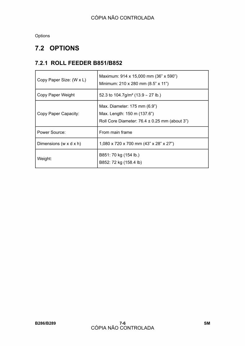
Options
B286/B289 7-6 SM
7.2 OPTIONS
7.2.1 ROLL FEEDER B851/B852
Copy Paper Size: (W x L) Maximum: 914 x 15,000 mm (36� x 590�)
Minimum: 210 x 280 mm (8.5� x 11�)
Copy Paper Weight 52.3 to 104.7g/m² (13.9 ∼ 27 lb.)
Copy Paper Capacity:
Max. Diameter: 175 mm (6.9�)
Max. Length: 150 m (137.6�)
Roll Core Diameter: 76.4 ± 0.25 mm (about 3�)
Power Source: From main frame
Dimensions (w x d x h) 1,080 x 720 x 700 mm (43� x 28� x 27�)
Weight: B851: 70 kg (154 lb.)
B852: 72 kg (158.4 lb)
CÓPIA NÃO CONTROLADA
CÓPIA NÃO CONTROLADA

Options
SM 7-7 B286/B289
Spec
ifica
tions
7.2.2 PAPER CASSETTE B853
Type Universal Cassette (installed in Roll Feeder B641/B642)
Paper Separation Friction Pad
Paper Capacity: 250 sheets
Copy Paper Size A3 SEF, A4 SEF, B4 SEF
LT SEF, LG SEF, DLT SEF, 8.5 x 13 SEF, 12 x 18 SEF
Copy Paper Weight 64 to105 g/m2 (17 to 28 lb)
Power Source From Roll Feeder
Weight 6 kg (13.2 lb)
CÓPIA NÃO CONTROLADA
CÓPIA NÃO CONTROLADA

Main Machine Configuration
B286/B289 7-8 SM
7.3 MAIN MACHINE CONFIGURATION
No. Item Machine Code
1 Main Machine B286
2 Interface PCB Type 3600 D329
3 Table Type 240 B854
4 Roll Feeder Type 240A/B B851/B852
5 Rear Stacker (Option for copies) D312
6 Original Hanger (Option for originals) D311
7 Paper Cassette Type 240 B853
8 Roll Holder Type A B394
CÓPIA NÃO CONTROLADA
CÓPIA NÃO CONTROLADA