Relatório Final de Instrumentação para o Ensino Dilatação...
24
1 Relatório Final de Instrumentação para o Ensino Dilatação Térmica e Termostato UNICAMP – Instituto de Física Gleb Wataghin Data: 12/06/2005 Autor: Fernando Rafael Reichert Orientador: Francisco das Chagas Marques 1. OBJETIVO O objetivo do projeto é expor um fenômeno de dilatação térmica, no qual dois materiais rigidamente afixados são forçados a se curvarem devido a diferentes coeficientes de dilatação térmica. O experimento descreve a base de funcionamento de um termostato, utilizado em vários dispositivos de nosso cotidiano, como ferro de passar e geladeira. Esse experimento pode então ser utilizado como demonstração qualitativa do fenômeno de dilatação térmica em salas de aula do ensino médio. 2. INTRODUÇÃO O experimento trata do fenômeno de dilatação térmica de sólidos e fenômenos que decorrem com variações deste comportamento de material para material, como o termostato. O experimento consiste em manter materiais diferentes rigidamente ligados e de diferentes coeficientes de expansão térmica. Deste modo, quando submetidos a uma variação de temperatura, são forçados a se curvar, pois não se dilatam igualmente. Este comportamento pode ser utilizado para estabelecer ou interromper um circuito elétrico (base de funcionamento de um termostato). O fenômeno é ilustrado na figura 1. 19-
Transcript of Relatório Final de Instrumentação para o Ensino Dilatação...

1
Relatório Final de Instrumentação para o Ensino Dilatação Térmica e Termostato
UNICAMP – Instituto de Física Gleb Wataghin
Data: 12/06/2005
Autor: Fernando Rafael Reichert
Orientador: Francisco das Chagas Marques
1. OBJETIVO
O objetivo do projeto é expor um fenômeno de dilatação térmica, no qual dois materiais rigidamente afixados são forçados a se curvarem devido a diferentes coeficientes de dilatação térmica. O experimento descreve a base de funcionamento de um termostato, utilizado em vários dispositivos de nosso cotidiano, como ferro de passar e geladeira. Esse experimento pode então ser utilizado como demonstração qualitativa do fenômeno de dilatação térmica em salas de aula do ensino médio.
2. INTRODUÇÃO
O experimento trata do fenômeno de dilatação térmica de sólidos e fenômenos que decorrem com variações deste comportamento de material para material, como o termostato.
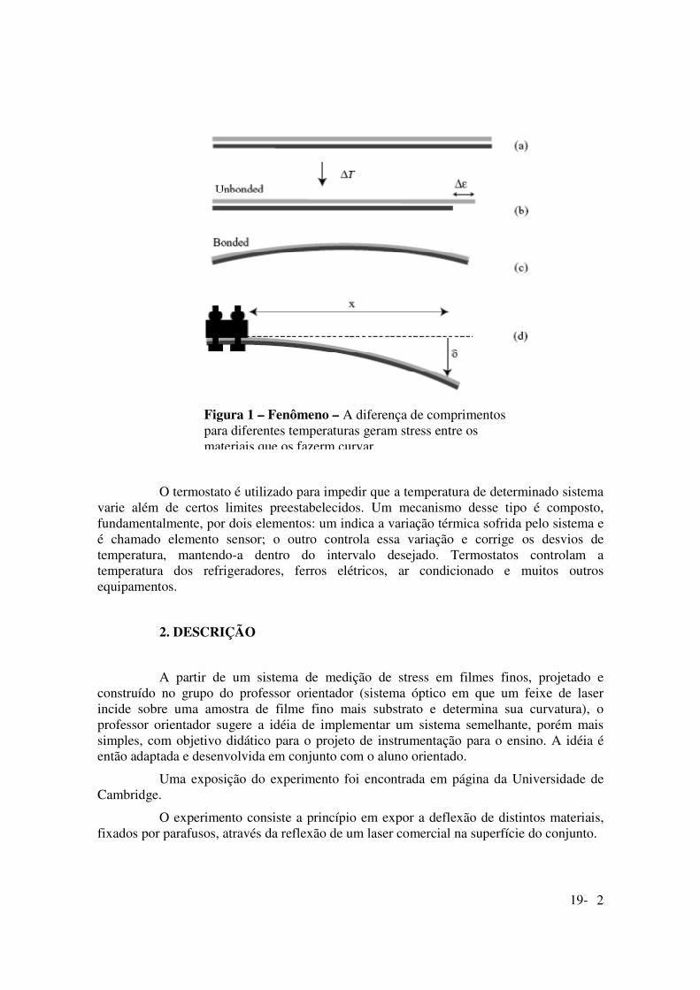
O experimento consiste em manter materiais diferentes rigidamente ligados e de diferentes coeficientes de expansão térmica. Deste modo, quando submetidos a uma variação de temperatura, são forçados a se curvar, pois não se dilatam igualmente. Este comportamento pode ser utilizado para estabelecer ou interromper um circuito elétrico (base de funcionamento de um termostato). O fenômeno é ilustrado na figura 1.
19-
2
O termostato é utilizado para impedir que a temperatura de determinado sistema varie além de certos limites preestabelecidos. Um mecanismo desse tipo é composto, fundamentalmente, por dois elementos: um indica a variação térmica sofrida pelo sistema e é chamado elemento sensor; o outro controla essa variação e corrige os desvios de temperatura, mantendo-a dentro do intervalo desejado. Termostatos controlam a temperatura dos refrigeradores, ferros elétricos, ar condicionado e muitos outros equipamentos.
2. DESCRIÇÃO
A partir de um sistema de medição de stress em filmes finos, projetado e construído no grupo do professor orientador (sistema óptico em que um feixe de laser incide sobre uma amostra de filme fino mais substrato e determina sua curvatura), o professor orientador sugere a idéia de implementar um sistema semelhante, porém mais simples, com objetivo didático para o projeto de instrumentação para o ensino. A idéia é então adaptada e desenvolvida em conjunto com o aluno orientado.
Uma exposição do experimento foi encontrada em página da Universidade de Cambridge.
O experimento consiste a princípio em expor a deflexão de distintos materiais, fixados por parafusos, através da reflexão de um laser comercial na superfície do conjunto.
Figura 1 – Fenômeno – A diferença de comprimentos para diferentes temperaturas geram stress entre os materiais que os fazerm curvar.
19-

3
Para aquecer o sistema será utilizado uma lâmpada dicróica, a qual possui a vantagem de não possuir inércia à dissipação como o caso de um contato metálico. Assim é buscado um experimento factível em tempo reduzido.
Diferentes materiais podem ser utilizados (material A e B da figura 2), preferencialmente materiais com coeficientes de dilatação térmica bastante distintos, o que implica em um ângulo de deflexão de maior percepção.
3. MATERIAIS UTILIZADOS:
A lâmpada dicróica obtida possui potência de 500W, tensão de 120V e, portanto uma corrente aproximada de 4,2A. Os contatos elétricos e fiação devem suportar, portanto essa corrente-potência.
Devido à alta temperatura atingida pela lâmpada, para proteção do observador e para possibilitar a observação do feixe de laser, a lâmpada foi instalada dentro de uma caixa metálica. Os cuidados a serem tomados são não olhar diretamente para a lâmpada e manter a caixa a uma temperatura abaixo de 350°C.
Escolhemos como bimetais uma lâmina de ferro (15x2x0.03)cm e outra de alumínio (15x2x0.05)cm, devido à disponibilidade e às características termo-mecânicas (módulo de young e coeficiente de dilatação térmico), as quais foram afixadas por rebite nas quatro pontas.
A montagem experimental é exposta nas figuras 2 (esquerda) e 3 (direita):
Para a exposição será necessário tomada 110V.
19-

4
4. MÉTODO:
Quando o equilíbrio térmico é alcançado, a curvatura resultante κ, (recíproco do
raio de curvatura) é relacionado ao ângulo de curvatura θ e distância x (fig. 3).
A curvatura pode então ser obtida das relações geométricas abaixo:
yx=)cos(θ
Ry
sen2
)( =θ x
sen )2( θκ =
A curvatura κ também pode ser obtida através de de propriedades e dimensões dos materiais, através da relação abaixo:
Onde EA e EB são os módulos de Young, hA e hB são as espessuras dos mesmos
e ∆ε a diferença de comprimento (fig. 1), dada por:
TBA ∆−=∆ )( ααε
Onde α são as constantes de dilatação térmica dos materiais e ∆T a variação da temperatura, tomando como base temperatura ambiente (temperatura em que os materiais foram unidos).
O módulo de Young pode ser entendido como a facilidade com a qual o material se curva, ou seja, o stress apresentado sob uma determinada tensão.
Figura 4 – Ângulo de deflexão – A curvatura é obtida através do ângulo de deflexão e do comprimento do material (aproximado por x).
y
19-

5
εσ=E
Onde σ é o stress e ε a tensão.
4.1 – Termostato Relacionando as curvaturas obtidas pelos dois métodos, podemos determinar a
temperatura que as lâminas se encontram. Caso queiramos que o termostato acione à temperatura T, um contato deve ser instalado à uma distância δ(T) da posição original, dada pela relação abaixo:
yT
sen)(
)(δθ =
)(2
)(2
Tsen
Tκ
θδ =
Obtemos, portanto, uma relação entre a temperatura do material e δ, permitindo assim, a montagem de um termostato.
4.2 – Deflexão em função da temperatura
Sabendo os valores dos módulos de Young dos materiais (Alumínio = 29 /1069 mN⋅ e ferro = 29 /10190 mN⋅ ), dos coeficientes de dilatação linear (Alumínio =
( ) 161025 −− °⋅ C e ferro = ( ) 161012 −− °⋅ C ), as espessuras (Alumínio = 0,5 mm e ferro =
0,3mm).
É possível então obter um valor teórico para a curvatura:
T∆⋅⋅= −2104375,2κ
Através do aparato experimental montado podemos verificar a validade deste modelo.
5. RESULTADOS
Como podemos ver nas figura 2 e 3, foram obtidos as normais à lâmina bimetálica para duas temperaturas diferentes.
Supondo que a lâmina seja reta à temperatura ambiente, ou seja, curvatura nula, o sistema apresentará a estrutura da figura 5.
19-
6
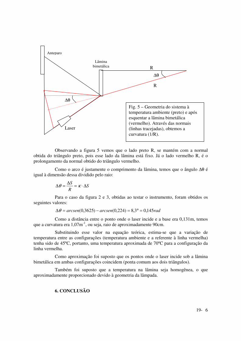
Observando a figura 5 vemos que o lado preto R, se mantém com a normal
obtida do triângulo preto, pois esse lado da lâmina está fixo. Já o lado vermelho R, é o prolongamento da normal obtido do triângulo vermelho.
Como o arco é justamente o comprimento da lâmina, temos que o ângulo ∆θ é igual à dimensão dessa dividido pelo raio:
SRS ∆⋅=∆=∆ κθ
Para o caso da figura 2 e 3, obtidas ao testar o instrumento, foram obtidos os seguintes valores:
radarcsenarcsen 145,03,8)224,0()3625,0( =°=−=∆θ
Como a distância entre o ponto onde o laser incide e a base era 0,131m, temos que a curvatura era 1,07m-1, ou seja, raio de aproximadamente 90cm.
Substituindo esse valor na equação teórica, estima-se que a variação de temperatura entre as configurações (temperatura ambiente e a referente à linha vermelha) tenha sido de 45ºC, portanto, uma temperatura aproximada de 70ºC para a configuração da linha vermelha.
Como aproximação foi suposto que os pontos onde o laser incide sob a lâmina bimetálica em ambas configurações coincidem (ponta comum aos dois triângulos).
Também foi suposto que a temperatura na lâmina seja homogênea, o que aproximadamente proporcionado devido à geometria da lâmpada.
6. CONCLUSÃO
Lâmina bimetálica
R
R
∆θ
∆θ
Fig. 5 – Geometria do sistema à temperatura ambiente (preto) e após esquentar a lâmina bimetálica (vermelho). Através das normais (linhas tracejadas), obtemos a curvatura (1/R).
Laser
Anteparo
19-

7
Através do modelo teórico foi possível estimar a temperatura de uma lâmina bimetálica em função do raio de curvatura medido experimentalmente.
O princípio de funcionamento de um termostato foi exposto. Através desse buscamos tornar acessível a exposição de conceitos básicos de materiais, como módulo de Young e de coeficiente de dilatação térmica.
Também é possível através do experimento expor conceitos de ótica e de geometria.
O resultado é uma exposição envolvendo diversos conceitos físicos e matemáticos, aplicável tanto à cursos de ensino médio, como à laboratórios básicos da graduação.
6. REFERÊNCIAS:
Sala de física: http://geocities.yahoo.com.br/saladefisica7/funciona/termostato.htm
Sala de Física Como Funciona
TERMOSTATO
A função do termostato é impedir que a temperatura de determinado sistema varie além de certos limites preestabelecidos. Um mecanismo desse tipo é composto, fundamentalmente, por dois elementos: um indica a variação térmica sofrida pelo sistema e é chamado elemento sensor; o outro controla essa variação e corrige os desvios de temperatura, mantendo-a dentro do intervalo desejado. Termostatos controlam a temperatura dos refrigeradores, ferros elétricos, ar condicionado e muitos outros equipamentos.
19-
8
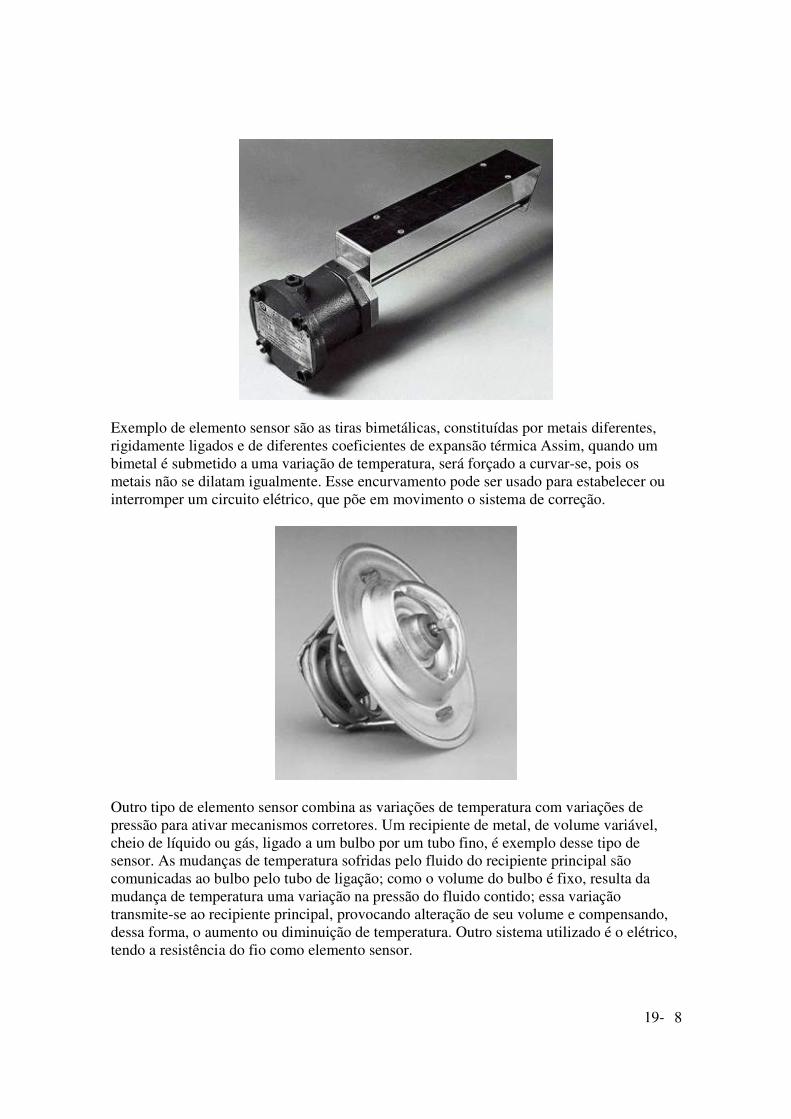
Exemplo de elemento sensor são as tiras bimetálicas, constituídas por metais diferentes, rigidamente ligados e de diferentes coeficientes de expansão térmica Assim, quando um bimetal é submetido a uma variação de temperatura, será forçado a curvar-se, pois os metais não se dilatam igualmente. Esse encurvamento pode ser usado para estabelecer ou interromper um circuito elétrico, que põe em movimento o sistema de correção.
Outro tipo de elemento sensor combina as variações de temperatura com variações de pressão para ativar mecanismos corretores. Um recipiente de metal, de volume variável, cheio de líquido ou gás, ligado a um bulbo por um tubo fino, é exemplo desse tipo de sensor. As mudanças de temperatura sofridas pelo fluido do recipiente principal são comunicadas ao bulbo pelo tubo de ligação; como o volume do bulbo é fixo, resulta da mudança de temperatura uma variação na pressão do fluido contido; essa variação transmite-se ao recipiente principal, provocando alteração de seu volume e compensando, dessa forma, o aumento ou diminuição de temperatura. Outro sistema utilizado é o elétrico, tendo a resistência do fio como elemento sensor.
19-

9
http://br.geocities.com/saladefisica
ÍNDICE COMO FUNCIONA
ÍNDICE GERAL Texas A&M University Kingsville http://physics.tamuk.edu/~suson/html/1401/thermal.html
Thermal Expansion Lets consider a solid bar that is initially at thermal equilibrium with the outside air. Now place a burner under the solid and see what happens. We would observe that the length would change in a manner proportional to the change in temperature and to the initial length. This can be written mathematically as ∆L = α L0 ∆T (75) The constant α, which characterizes the thermal expansion properties of a specific material, is called the coefficient of linear expansion. It should be noted that (75) is only an approximate relationship. It varies somewhat depending on the initial temperature and the size of the temperature change.
Thermal Stress Now consider what happens if we take an object and clamp it so that its length is fixed. As it heats up, it will generate a tensile or compressive stress in the material. In order to determine the amount of stress created, notice that (75) can be rearranged to read
∆L/L0 = α ∆T
19-

10
This would be the fractional change in length if the object were allowed to change. Recall that the Young's modulus was defined to be
or
Since the object is not being allowed to expand, the sum of the thermal expansion and the tensile strain must be zero
α∆T + F/AY = 0
or
F/A = -αY∆T (77) Example: What is the magnitude of the stress generated in a piece of steel for a change of 1C°?
University of Cambridge http://www.doitpoms.ac.uk/tlplib/thermal-expansion/printall.php
DoITPoMS Teaching and Learning Packages
19-

11
Thermal expansion and the bi-material strip
Note: DoITPoMS Teaching and Learning Packages are intended to be used interactively at a computer! This one-page print-friendly version of the TLP is provided for convenience, but does not display all the content of the TLP. For example, any video clips and answers to questions are missing. The formatting (page breaks, etc) of the printed version is unpredictable and highly dependent on your browser.
The bi-material strip When a component made up of two different materials bonded together is heated or cooled, a misfit is generated between the new dimensions each would adopt if they were isolated. This mismatch can set up stresses and associated distortions. On the other hand, the effect can be exploited by using such a couple to detect or measure temperature changes. An example of such a sensor is the simple bimetallic strip, which has long been used in thermostats and other thermal devices.
As shown in the following diagram, if unbonded the free lengths of each material would be different after a temperature change. When bonded, however, the difference in unconstrained lengths gives rise to internal stresses within the strip, causing it to bend.
The bimaterial strip: (a) Two strips of equal initial length undergo (b) a temperature change ∆T, such that the relative difference in their unconstrained lengths is ∆ε (= ∆α ∆T). (c) Since the two strips are in fact bonded together, the resulting internal stresses generate a uniform curvature. (d) Clamping a bimaterial strip, to allow measurement of the deflection and hence the curvature.
19-

12
When thermal equilibrium is reached, the resulting curvature, κ, (reciprocal of the radius of curvature) is related to the displacement, δ, and the distance, x, along the strip at which the displacement is being measured by the relationship
(3)
This can be derived using the geometrical construction shown below.
Geometry for derivation of equation (3)
i.e.
The curvature is also related to the material properties and dimensions through the equation
(4)
where EA, EB are the Young's Moduli, and hA, hB the thicknesses of the two materials A and B. The misfit strain, ∆ε, is given by
19-

13
∆ε = (αA - αB)∆T (5)
where aA and aB are the thermal expansivities of the constituents. Derivation of equation (4) is not particularly complex, but need not concern us (see Clyne T W, Key Engineering Materials, vol.116/117 (1996) p.307-330). It is based on the balancing of the bending moment generated by the misfit strain against the opposing moment offered by the beam.
It can be seen that the curvature depends, not just on the expansivity mismatch and temperature change, but also on the relative stiffness and thickness of the two materials. If the two strips are of equal thickness (h), and the stiffness ratio is termed E*, the equation can be re-written
(6)
It can be seen that there is a scale effect - i.e. the curvature will be greater when the strips are thinner. Furthermore, a glance at the denominator shows that the curvature will be small if one of the materials has a much greater stiffness than the other.
Assuming the α values for steel and aluminium given in the properties table to be correct, it is possible to use eqns. (3), (5) and (6) to estimate the value of ∆T corresponding to a measured curvature of the steel - Al strip and hence estimate the boiling temperature of liquid nitrogen.
Definition of Young's Modulus For solids that obey Hooke's Law:
Young's Modulus (E) is the ratio of tensile stress (σ) to tensile strain (ε) in a specimen subject to uniaxial tension.
This definition then begs for definitions of the terms within it.
For a force tending to elongate a specimen, the tensile stress is the ratio of the *force* (F) applied in a particular direction in the specimen to the cross-sectional area (A) of the specimen in a plane normal to the direction of the applied force.
19-

14
(* Strictly speaking, to achieve equilibrium this has to be a pair of equal and opposite forces acting along that direction.)
[If the direction of application of the force is reversed so that the force tends to shorten the sample, the stress is called "compressive".]
If an increment in the tensile stress applied to a specimen of length (l) produces an increment in length (δl) parallel to the direction of application of the stress, the increment in tensile strain (δε) is given by
and the "true" or "logarithmic" tensile strain (ε) is given by
For small strains it is often sufficient to approximate the true strain by the "nominal" or "engineering" strain (e)
Uniaxial tension means that the only externally applied forces acting on the specimen are a pair of equal and opposite forces acting along a line.
Beam deflection during cantilever bending
The beam curvature, κ, is approximately equal to the curvature of the line traced by the neutral axis, d2y/dx2 (see diagram below), so that
where M is the bending moment, E is the Young's modulus and I is the second moment of area. Applying this to the end-loaded cantilever beam, and taking the moment as positive when it generates a displacement in the downward direction (+ive y)
where F is the load applied at the end of the beam.
19-

15
Approximation involved in equating beam curvature to the curvature of the neutral axis (Click on image for larger version)
The deflection is found by integrating this expression, using boundary conditions to establish the integration constants
The deflections along the length of the beam, and specifically at the loaded end, are thus given by
19-

16
Mechanical and thermal properties of some engineering materials
Material Young's modulus
(GPa)
Density (Mg m-3)
Thermal expansivity
(K-1 x 10⁻⁶)
Thermal conductivity
(W m-1 K-1) Mild Steel 208 7.8 15 60 Aluminium 70 2.8 23 230 Titanium 115 4.5 9.5 22 Copper 117 8.9 17 390 Thermoplastic (e.g. Nylon 6)
~2 1.1 ~90 0.2
Thermoset (e.g. Epoxy resin)
~3 1.3 ~60 0.1
Alumina 300 3.9 8 30
Mechanical and thermal properties of some engineering materials
Academic consultant: Bill Clyne Content development: Sam Burke, Dave Hudson Photography and video: Brian Barber and Carol Best Web development: Sam Burke and Dave Hudson
DoITPoMS is funded by the Higher Education Funding Council for England (HEFCE) and the Department for Employment and Learning (DEL) under the Fund for the Development of Teaching and Learning (FDTL). © University of Cambridge DoITPoMS, Department of Materials Science and Metallurgy, University of Cambridge Information provided by [email protected]. This is a print-friendly version of the TLP at: http://www.doitpoms.ac.uk/tlplib/thermal-expansion
Feira de Ciências http://www.feiradeciencias.com.br/sala08/08_35.asp
Termômetro bimetálico
19-

17
Prof. Luiz Ferraz Netto [email protected]
Comecemos pelo bimetal, que consiste numa chapa composta de duas folhas de metais diferentes passadas no laminador a temperatura bastante elevada que faz com que elas adiram fortemente uma à outra. Às vezes, ao invés da técnica do laminador, as duas folhas são justapostas e soldadas à ponto.
As lâminas de bimetal são fabricadas para diversos fins; por exemplo: para unir, a resistência mecânica de uma folha, com a elevada resistência à corrosão de outra; ou mesmo para aproveitar os efeitos dos diferentes coeficientes de dilatação térmica; esse último é o que nos interessa no momento. De fato, se unirmos duas lâminas metálicas que têm coeficientes de dilatação lineares αααα1111,α,α,α,α2222 muito diferente, a deformação provocada pelos diferentes alongamentos, ou contrações, das partes sob a ação de uma variação de temperatura, pode ser usada para diversas aplicações.
Para tais aplicações a forma mais usual do bimetal é a lâmina bimetálica, constituída de duas tiras finas de diferentes metais, que se faz aderir face a face com um processo de laminação ou de compressão. À certa temperatura (de repouso) as duas tiras têm o mesmo comprimento e a lâmina se apresenta plana, posição (1) na ilustração.
Um aumento de temperatura provoca nela a uniforme flexão no sentido do comprimento de modo que o metal A, menos sensível às variações térmicas, permanece no interior da concavidade (posição 2), ou seja, na face côncava. Uma diminuição de temperatura provoca a deformação inversa (posição 3) ficando o material A (menor coeficiente de dilatação linear) na face convexa.
Os materiais usados correntemente são ligas de ferro e níquel cujos coeficientes de dilatação linear dependem fortemente da porcentagem de níquel; se esta porcentagem é de 36% obtém-se a liga invar que possui um αααα extremamente pequeno (daí seu nome, invariável). O latão e o invar constituem um bom par para a lâmina bimetálica. Para uma lâmina como a da ilustração acima pode-se assumir h como a medida da deformação provocada por uma variação de temperatura ∆θ∆θ∆θ∆θ em relação à de repouso: em primeira aproximação a deformação é dada por:
h = (2L2/s).∆α∆α∆α∆α.∆θ∆θ∆θ∆θ
19-

18
onde L é o comprimento natural da lâmina, s é sua espessura e ∆α∆α∆α∆α representa a diferença entre os coeficientes de dilatação linear dos dois materiais. Para uma lâmina ferro-invar com L = 30 mm, s = 0,5 mm e para ∆θ∆θ∆θ∆θ = 1 oC, resulta h ~ 0,04 mm.
As dimensões das lâminas bimetálicas dependem das características de robustez, de sensibilidade e de rapidez requeridas para as suas diversas aplicações; a espessura é geralmente compreendida entre 0,05 a 5 mm. Nos dispositivos com lâmina bimetálica uma extremidade da lâmina é mantida fixa e é usado o deslocamento da extremidade livre para efetuar alguma ação. Tal deslocamento, eventualmente ampliado, pode ser transmitido a um indicador móvel sobre uma escala graduada: o dispositivo, uma vez calibrado, constitui um termômetro bimetálico (muito comum em tampas de fornos dos fogões a gás).
Mais freqüente é o uso de lâminas bimetálicas em aparelhos que efetuam automaticamente a abertura e o fechamento de um circuito elétrico onde a comutação pode ocorrer para valores preestabelecidos de temperatura. Eis uma ilustração didática para um alarme contra incêndio:
Aplicações típicas e muito difundidas são constituídas pelos interruptores de pulsação automática (intermitentes) nos quais o ligar e desligar de uma ou mais lâmpadas são comandados por uma lâmina bimetálica aquecida por um um resistor de resistência R em série com a lâmpada. Os termo-reguladores ou termostatos e os interruptores automáticos de sobrecarga funcionam sob este princípio básico das lâminas bimetálicas (abaixo, à direita). Nas decorações de árvores de natal mediante pequenas lâmpadas, uma das lâmpadas usa o próprio calor dissipado em seu funcionamento para acionar um interruptor bimetálico, em série (abaixo, à esquerda).
19-
19
Wikipedia, the free encyclopedia
http://en.wikipedia.org
Bi-metal
From Wikipedia, the free encyclopedia. (Redirected from Bimetal)
This page concerns the temperature-sensitive mechanical device. For bi-metal electrical devices see thermocouple and Peltier-Seebeck effect. For metals composed of a mixture of two or more metallic elements see alloy.
Contents 1 Fundamentals 2 Applications
2.1 Thermostats 2.2 Thermometers [edit]
Fundamentals A bi-metallic strip is used to convert a temperature change into mechanical displacement.
The strip consists of two layers, usually iron and copper. The two layers are joined together to form the strip.
Owing to the difference in the constants of expansion of the two materials, a flat strip will bend one way (toward the iron part) if heated, and in the opposite direction if cooled below its normal temperature.
In some applications the bi-metal strip is used in the flat form. In others, it is wrapped into a coil, which gives greater sensitivity in a compact space.
[edit]
Applications [edit]
19-

20
Thermostats
In regulating thermostats that operate over a wide range of temperatures the bi-metal strip is mechanically fixed and attached to an electrical power source while the other (moving) end carries an electrical contact. In adjustable thermostats another contact is positioned with a regulating knob or lever. The position so set controls the regulated temperature, called the set point.
Some thermostats use a mercury switch connected to both electrical leads. The angle of the entire mechanism is adjustable to control the set point of the thermostat.
Depending upon the application, a higher temperature may open a contact (as in a heater control) or it may close a contact (as in a refrigerator or air conditioner.
The electrical contacts may control the power directly (as in a household iron) or indirectly, switching electrical power through a relay or the supply of natural gas or fuel oil through an electrically operated valve. In some natural gas heaters the power may be provided with a thermocouple that is heated by a pilot light (a small, continuously burning flame). In devices without pilot lights for ignition (as in most modern gas clothes dryers and some natural gas heaters and decorative fireplaces) the power for the contacts is provided by reduced household electrical power that operates a relay controlling an electronic ignitor, either a resistance heater or an electrically powered spark generating device.
For an illustration of a bi-metal element in a simple thermostat, see the thermostat entry.
[edit]
Thermometers
A direct indicating dial thermometer (such as a patio thermometer or a meat thermometer) uses a bi-metallic strip wrapped into a coil, as does a common household thermostat. One end of the coil is fixed to the chassis of the device and the other is connected to an indicating needle.
Retrieved from "http://en.wikipedia.org/wiki/Bi-metal"
Young's modulus
From Wikipedia, the free encyclopedia.
In solid mechanics, Young's modulus (also known as the modulus of elasticity or elastic modulus) is a measure of the stiffness of a given material. It is defined as the limit for small strains of the rate of change of stress with strain. This can be experimentally determined from the slope of a stress-strain curve created during tensile tests conducted on
19-
21
a sample of the material. Young's modulus is named after Thomas Young the English physicist, physician, and Egyptologist.
Contents 1 Units 2 Usage
2.1 Linear vs Non-linear 2.2 Directional Materials
3 Calculation
3.1 Tension 3.2 Elastic potential energy
4 Approximate values 5 See also [edit]
Units The SI unit of modulus of elasticity is the pascal. However, given the large values typical of many common materials, figures are often quoted in megapascals or gigapascals for convenience.
The modulus of elasticity can also be measured in other units of pressure, for example pounds per square inch (psi).
[edit]
Usage The Young's modulus allows the behavior of a material under load to be calculated. For instance, it can be used to predict the amount a wire will extend under tension, or to predict the load at which a thin column will buckle under compression. Some calculations also require the use of other material properties, such as the shear modulus, density, or Poisson's ratio.
[edit]
Linear vs Non-linear
For many materials, Young's modulus is a constant over a range of strains. Such materials are called linear, and are said to obey Hooke's law. Examples of linear materials include steel, carbon fiber, and glass. Rubber is a non-linear material.
19-

22
[edit]
Directional Materials
Most metals and ceramics, along with many other materials, are uniform - their mechanical properties are the same in all directions.
However, this is not always the case. Some materials, particularly those which are composites of two or more ingredients have a "grain" or similar mechanical structure. As a result, they have different mechanical properties when load is applied in different directions. For example, carbon fiber is much stiffer (higher Young's Modulus) when loaded parallel to the fibers (along the grain). Other such materials include wood and reinforced concrete.
[edit]
Calculation The modulus of elasticity, �, can be calculated by dividing the stress by the strain, i.e.
where (in SI units)
� is the modulus of elasticity, measured in pascals
F is the force, measured in newtons
A is the cross-sectional area through which the force is applied, measured in square metres
x is the extension, measured in metres
l is the natural length, measured in metres
[edit]
Tension
The modulus of elasticity of a material can be used to calculate the tension force it exerts under a specific extension.
19-

23
where
T is the tension, measured in newtons
[edit]
Elastic potential energy
The elastic potential energy stored is given by the integral of this expression with respect to x, i.e. energy stored E is given by:
���������
���� ����
�������
where
E is the elastic potential energy, measured in joules
[edit]
Approximate values Note that Young's Modulus can vary considerably depending on the exact composition of the material. For example, the value for most metals can vary by 5% or more, depending on the precise composition of the alloy and any heat treatment applied during manufacture. As such, many of the values here are very approximate.
Approximate Young's Moduli of Various Solids
Material Young's modulus (E) in GPa
Young's modulus (E) in PSI
Rubber (small strain) 0.01-0.1 1,500-15,000
Polystyrene 3-3.5 435,000-505,000
Nylon 2-4 290,000-580,000
Oak wood (along grain) 11 1,600,000
High-strength concrete (under compression) 30 4,350,000
Magnesium metal 45 6,500,000
Glass 50-90 7,250,000-13,000,000
19-

24
Aluminium alloys 69 10,000,000
Brasses and bronzes 103-124 17,000,000
Titanium (Ti) 105-120 15,000,000-17,500,000
Carbon fiber reinforced plastic (unidirectional, along grain) 150 21,800,000
Wrought iron and steel 190-210 30,000,000
Tungsten (W) 400-410 58,000,000-59,500,000
Silicon carbide (SiC) 450 65,000,000
Tungsten carbide (WC) 450-650 65,000,000-94,000,000
Diamond 1,050-1,200 150,000,000-175,000,000
[edit]
See also • Deformation • Stress • Strain • Tensile_strength • Yield_strength • Toughness • Hardness
19-