Prédio Metálico - 1 Steel_Structure
87
Advanced Application 1 Steel Structure
-
Upload
vinicius-rebuli -
Category
Documents
-
view
61 -
download
0
Transcript of Prédio Metálico - 1 Steel_Structure
Advanced Application 1
Steel Structure

Application 1. Steel Structure
1
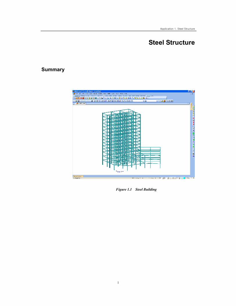
Steel Structure
Summary
Figure 1.1 Steel Building
Application 1. Steel Structure
2
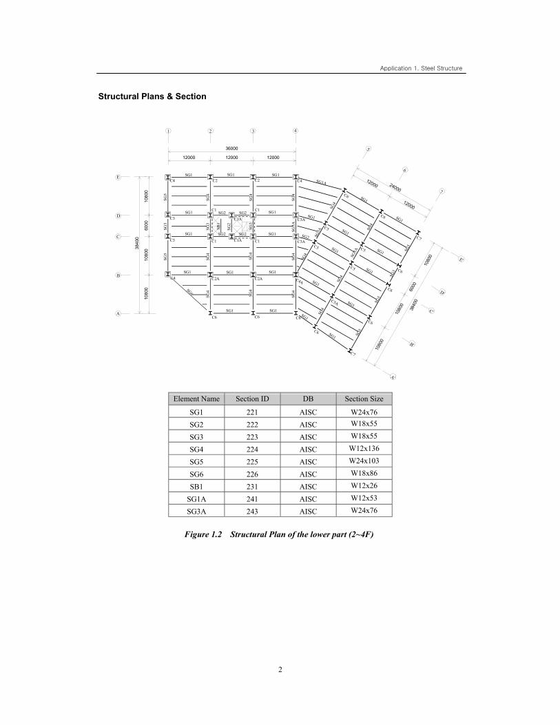
Structural Plans & Section
Element Name Section ID DB Section Size
SG1 221 AISC W24x76 SG2 222 AISC W18x55
SG3 223 AISC W18x55
SG4 224 AISC W12x136
SG5 225 AISC W24x103
SG6 226 AISC W18x86
SB1 231 AISC W12x26
SG1A 241 AISC W12x53
SG3A 243 AISC W24x76
Figure 1.2 Structural Plan of the lower part (2~4F)
SG2
SG2
1 2 3 4
1080
010
800
12000
6000
12000 12000
5
6
7
12000
12000
1080
0
1080
0
B'
C'
D'
E'
A'
1080
0
1080
0
B
C
D
E
A
SG2
C4
C4
C3
C3
C2 C2 C4
C3A
C3A
C1 C1
C1 C1
C1A
C1A
C2A C2A
C6 C6 C6
C4A
C5
C5
C6
C6
C7
C5
C5
C6
C6
C5A
C6
C6
C7
SG6
SG1 SG1 SG1
SG1 SG1 SG1
SG1
SG1
SG1
SG1A
SG1
SG2
SG1
SG1
SG
5 S
G5
SG
4 S
G4
SG
4 S
G4
SG
4 S
G4
SG
3
SG1
SG1 SG1
SG
4
SG
4
SG
4
SG1
SG
3
SG
3
SG2
SB
1
SG
2
SG
3A
SG3
A
SG4
SG4
SG4
SG5
SG4
SG5
SG4
SG5
SG3
A
SG3
SG1
SG1 SG1
SG1
SG1
SG1
SG1
36000
3840
0
6000
3840
0
24000
Application 1. Steel Structure
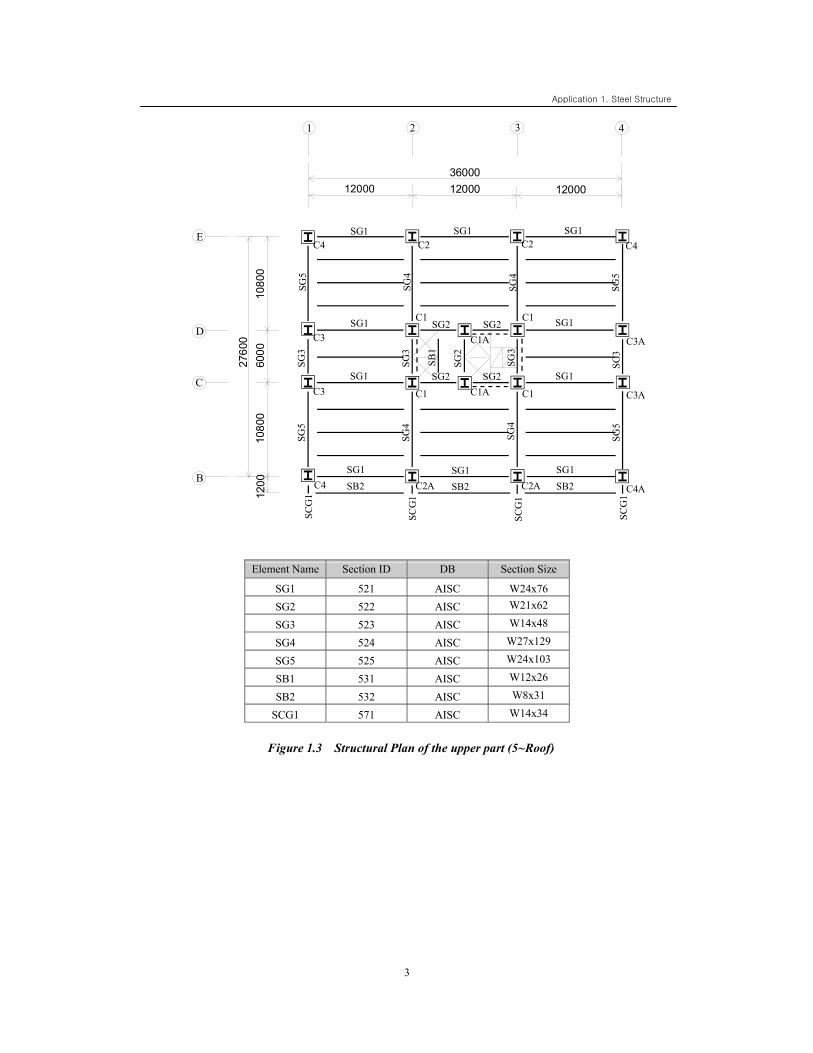
3
Element Name Section ID DB Section Size
SG1 521 AISC W24x76 SG2 522 AISC W21x62
SG3 523 AISC W14x48
SG4 524 AISC W27x129
SG5 525 AISC W24x103
SB1 531 AISC W12x26
SB2 532 AISC W8x31
SCG1 571 AISC W14x34
Figure 1.3 Structural Plan of the upper part (5~Roof)
SG2
SG2
1 2 3 4
1200
1080
0
12000
6000
12000 12000
1080
0
SG2
C4
C4
C3
C3
C2 C2 C4
C3A
C3A
C1 C1
C1 C1
C1A
C1A
C2A C2A
SG1 SG1 SG1
SG1
SG1
SG
5 S
G5
SG
4 S
G4
SG
4 S
G4
SG
5 S
G5
SG
3
SG1
SG1 SG1
SG1
SG
3
SG
3
SG2
SB
1
SG
2
SG
3
SG1 SB2 SB2 SB2 C4A
SC
G1
SC
G1
SC
G1
SCG
1
36000
2760
0
B
C
D
E
Application 1. Steel Structure
4
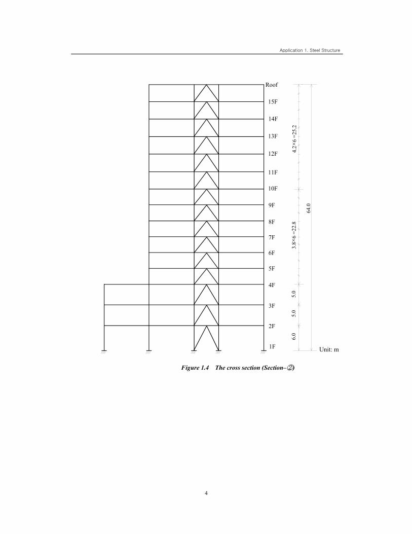
Figure 1.4 The cross section (Section–②)
3.8 ×
6 =2
2.8
5.0
5.0
6.0
단위 : m1F
2F
3F
4F
5F
6F
7F
8F
9F
10F
11F
12F
13F
14F
15F
Roof
4.2×
6 =2
5.2
64.0
Unit: m
Application 1. Steel Structure
5
Applied Codes
Applied Load / UBC(1997) Steel Design Code / AISC-LRFD2K SRC Design Code / SSRC79
Used Materials
Beam, Brace: A36
Column: A572-50 Concrete Grade C4000
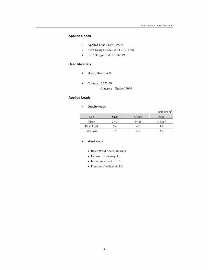
Applied Loads
Gravity loads
unit: kN/m2
Use Shop Office Roof
Floor 2∼3 4∼15 4, Roof Dead Load 3.6 4.2 5.1 Live Load 3.9 2.5 2.0
Wind loads
• Basic Wind Speed: 80 mph • Exposure Category: C • Importance Factor: 1.0 • Pressure Coefficient: 1.3
Application 1. Steel Structure
6
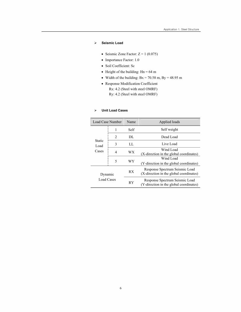
Seismic Load
• Seismic Zone Factor: Z = 1 (0.075) • Importance Factor: 1.0 • Soil Coefficient: Sc • Height of the building: Hn = 64 m • Width of the building: Bx = 70.58 m, By = 48.95 m • Response Modification Coefficient
Rx: 4.2 (Steel with steel OMRF) Ry: 4.2 (Steel with steel OMRF)
Unit Load Cases
Load Case Number Name Applied loads
1 Self Self weight
2 DL Dead Load
3 LL Live Load
4 WX Wind Load (X-direction in the global coordinates)
Static Load Cases
5 WY Wind Load
(Y-direction in the global coordinates)
RX Response Spectrum Seismic Load
(X-direction in the global coordinates) Dynamic Load Cases
RY Response Spectrum Seismic Load
(Y-direction in the global coordinates)
7
Structural Modeling
Initial Window & Unit System Setting
File / New Project
File / Save (Steel)
Tools / Unit System
Length > m ; Force > N
Tools / Customize / Toolbars
Joint On/Off > Node (on), Element (on), Property (on)
(Refer to Figure 1.5)
Point Grid (off), Point Grid Snap (off), Line Grid Snap (off)
Application 1. Steel Structure
8
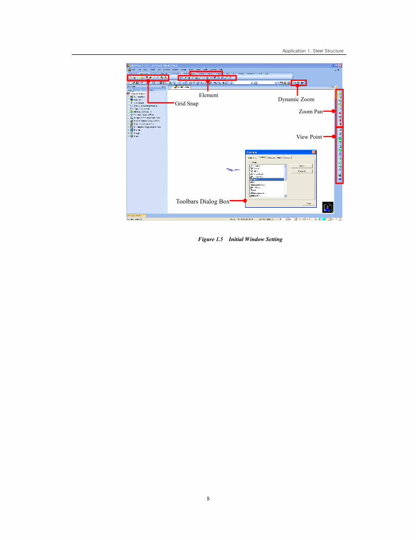
Figure 1.5 Initial Window Setting
Toolbars Dialog Box
Zoom Pan
View Point
Dynamic Zoom
Toolbars Dialog Box
Element Grid Snap
9
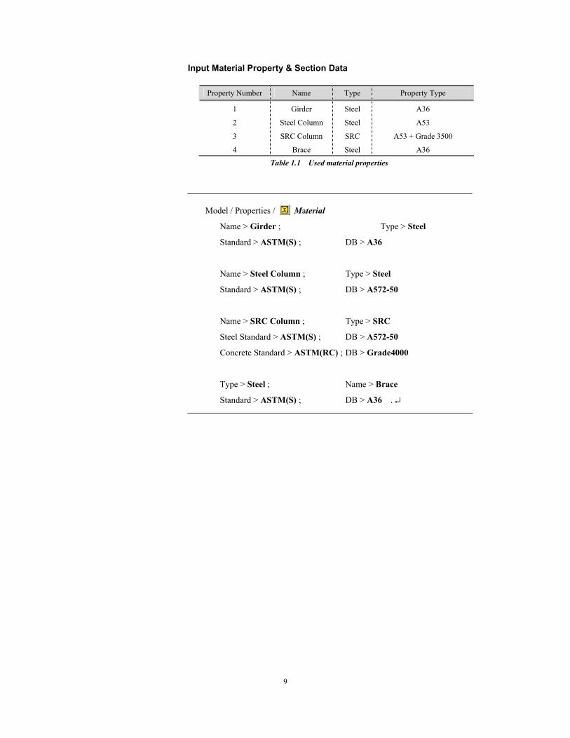
Input Material Property & Section Data
Property Number Name Type Property Type
1 Girder Steel A36
2 Steel Column Steel A53
3 SRC Column SRC A53 + Grade 3500
4 Brace Steel A36
Table 1.1 Used material properties
Model / Properties / Material
Name > Girder ; Type > Steel
Standard > ASTM(S) ; DB > A36
Name > Steel Column ; Type > Steel
Standard > ASTM(S) ; DB > A572-50
Name > SRC Column ; Type > SRC
Steel Standard > ASTM(S) ; DB > A572-50
Concrete Standard > ASTM(RC) ; DB > Grade4000
Type > Steel ; Name > Brace
Standard > ASTM(S) ; DB > A36 . ↵
Application 1. Steel Structure
10
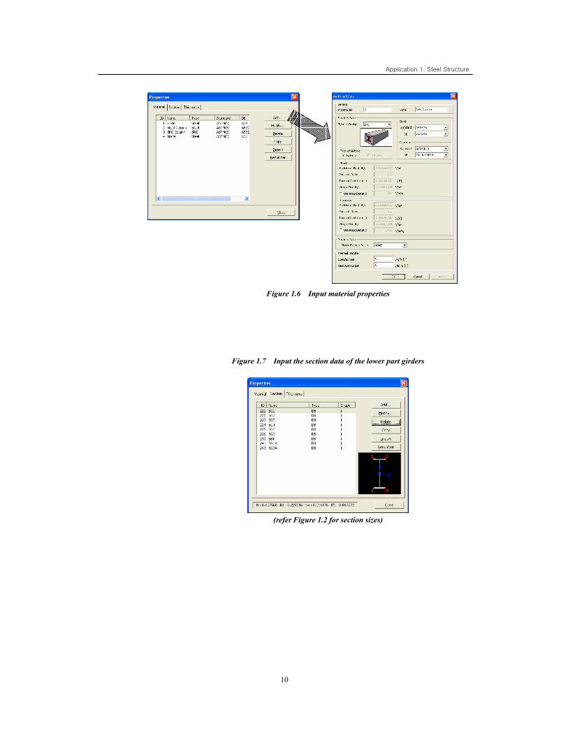
Figure 1.6 Input material properties
Figure 1.7 Input the section data of the lower part girders
(refer Figure 1.2 for section sizes)
11
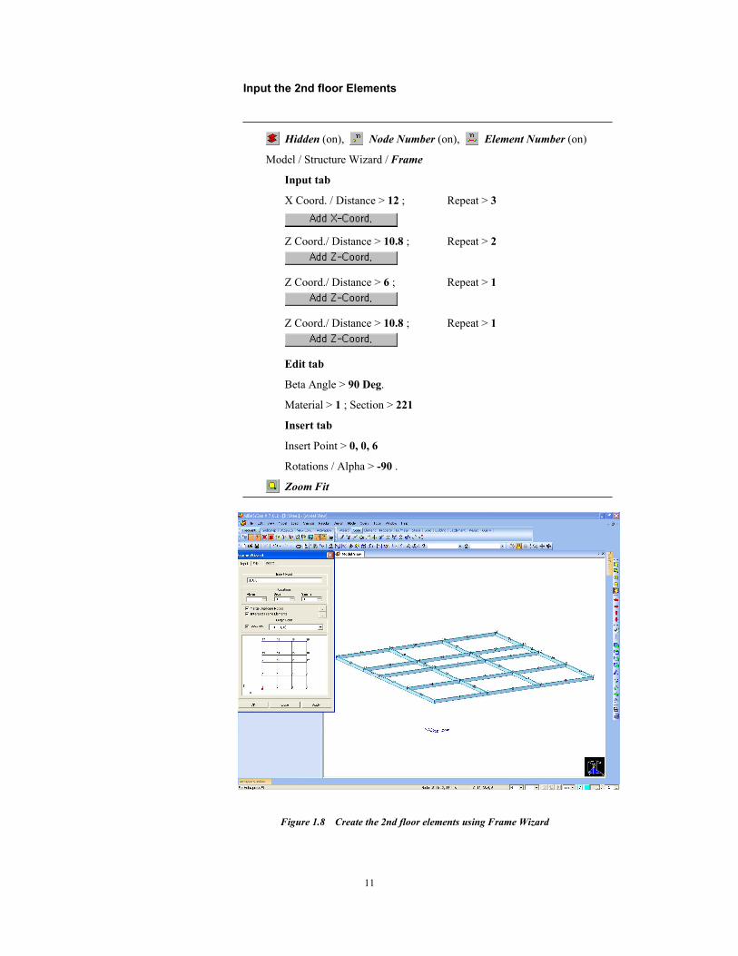
Input the 2nd floor Elements
Hidden (on), Node Number (on), Element Number (on)
Model / Structure Wizard / Frame
Input tab
X Coord. / Distance > 12 ; Repeat > 3
Z Coord./ Distance > 10.8 ; Repeat > 2
Z Coord./ Distance > 6 ; Repeat > 1
Z Coord./ Distance > 10.8 ; Repeat > 1
Edit tab
Beta Angle > 90 Deg.
Material > 1 ; Section > 221
Insert tab
Insert Point > 0, 0, 6
Rotations / Alpha > -90 .
Zoom Fit
Figure 1.8 Create the 2nd floor elements using Frame Wizard
Application 1. Steel Structure
12
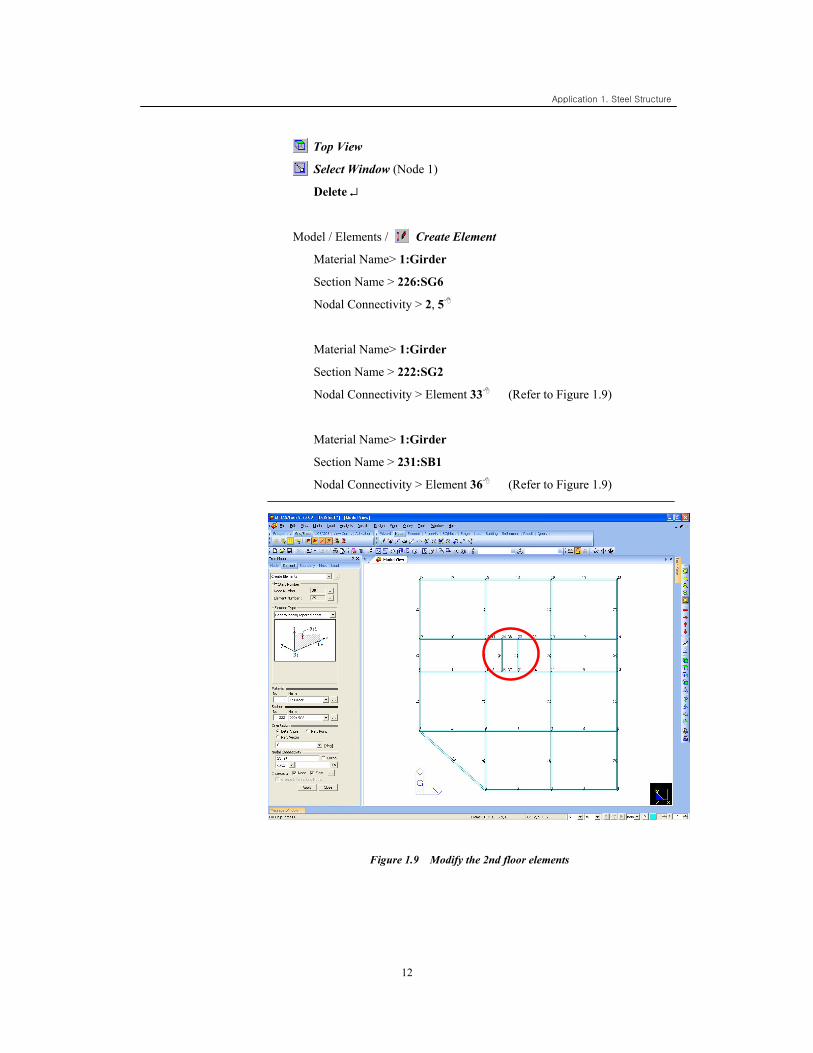
Top View
Select Window (Node 1)
Delete ↵
Model / Elements / Create Element
Material Name> 1:Girder
Section Name > 226:SG6
Nodal Connectivity > 2, 5
Material Name> 1:Girder
Section Name > 222:SG2
Nodal Connectivity > Element 33 (Refer to Figure 1.9)
Material Name> 1:Girder
Section Name > 231:SB1
Nodal Connectivity > Element 36 (Refer to Figure 1.9)
Figure 1.9 Modify the 2nd floor elements
13
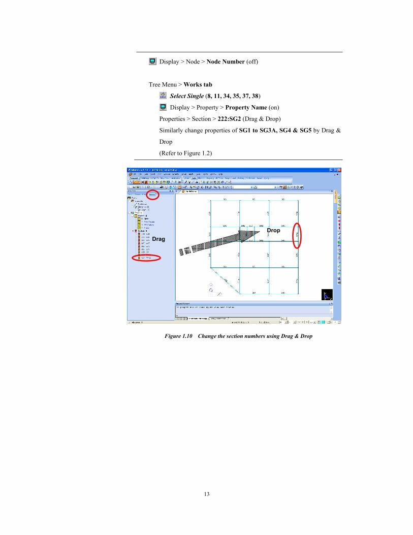
Display > Node > Node Number (off)
Tree Menu > Works tab
Select Single (8, 11, 34, 35, 37, 38)
Display > Property > Property Name (on)
Properties > Section > 222:SG2 (Drag & Drop)
Similarly change properties of SG1 to SG3A, SG4 & SG5 by Drag &
Drop
(Refer to Figure 1.2)
Figure 1.10 Change the section numbers using Drag & Drop
Drag Drop
Application 1. Steel Structure
14
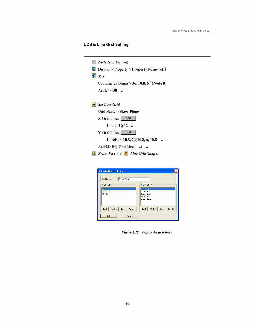
UCS & Line Grid Setting
Node Number (on)
Display > Property > Property Name (off)
X-Y
Coordinates Origin > 36, 10.8, 6 (Node 8)
Angle > -30 ↵
Set Line Grid
Grid Name > Skew Plane
X-Grid Lines
Line > 2@12 . ↵
Y-Grid Lines
Levels > -10.8, [email protected], 6, 10.8 ↵
Add/Modify Grid Lines ↵ ↵
Zoom Fit (on), Line Grid Snap (on)
Figure 1.12 Define the grid lines
15
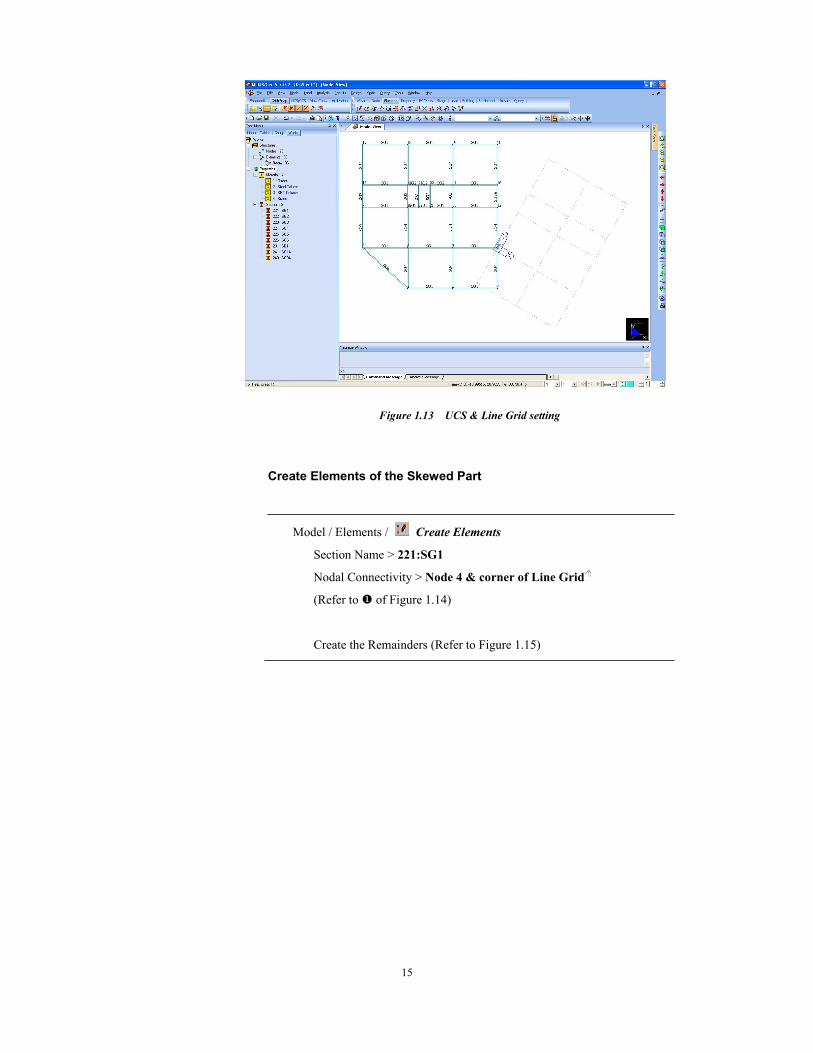
Figure 1.13 UCS & Line Grid setting
Create Elements of the Skewed Part
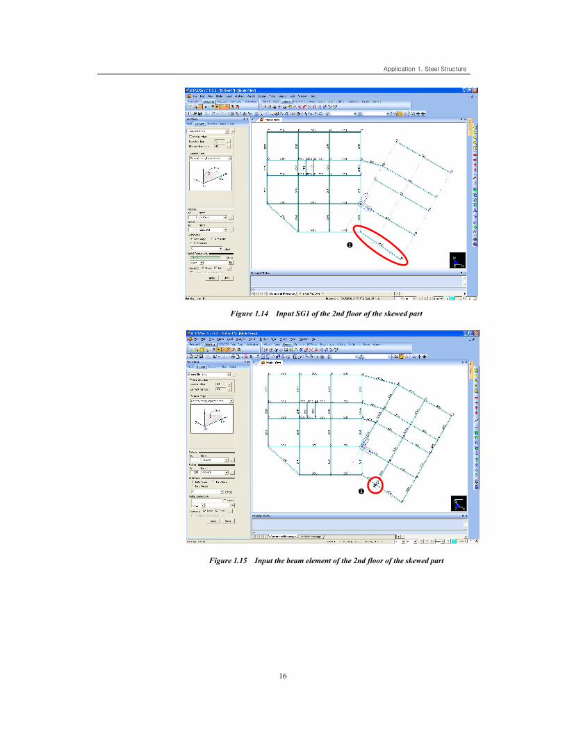
Model / Elements / Create Elements
Section Name > 221:SG1
Nodal Connectivity > Node 4 & corner of Line Grid
(Refer to of Figure 1.14)
Create the Remainders (Refer to Figure 1.15)
Application 1. Steel Structure
16
Figure 1.14 Input SG1 of the 2nd floor of the skewed part
Figure 1.15 Input the beam element of the 2nd floor of the skewed part
17
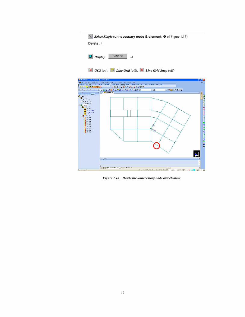
Select Single (unnecessary node & element; of Figure 1.15)
Delete ↵
Display ↵
GCS (on), Line Grid (off), Line Grid Snap (off)
Figure 1.16 Delete the unnecessary node and element
Application 1. Steel Structure
18
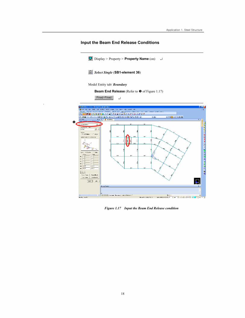
Input the Beam End Release Conditions
Display > Property > Property Name (on) ↵
Select Single (SB1-element 36)
Model Entity tab/ Boundary
Beam End Release (Refer to of Figure 1.17)
↵ .
Figure 1.17 Input the Beam End Release condition
19
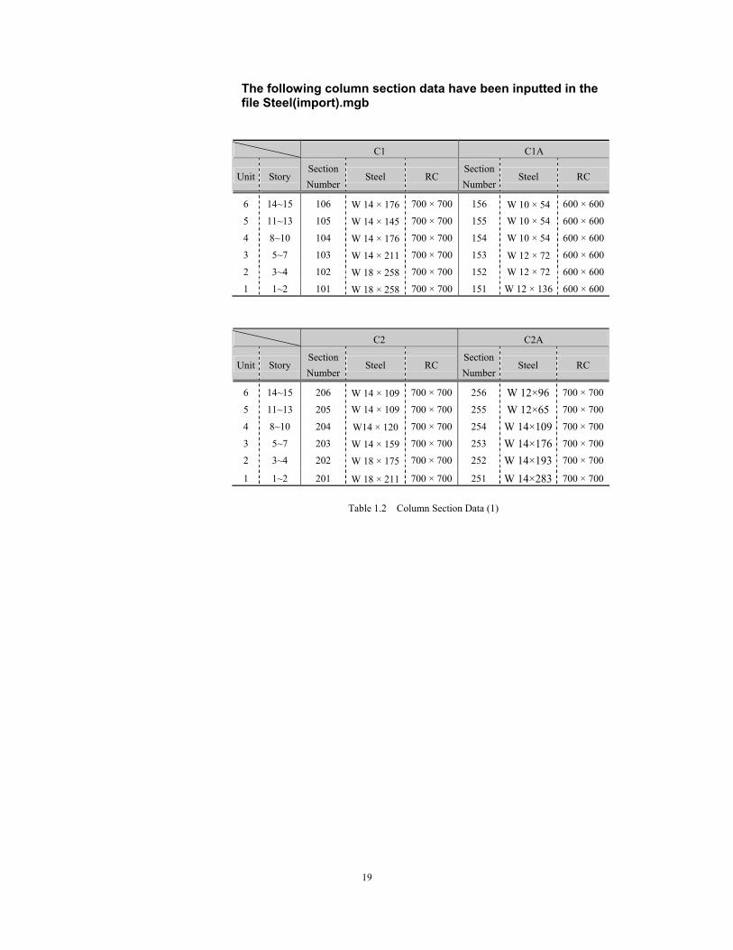
The following column section data have been inputted in the file Steel(import).mgb
C1 C1A
Unit Story Section Number
Steel RC Section Number
Steel RC
6 14~15 106 W 14 × 176 700 × 700 156 W 10 × 54 600 × 600
5 11~13 105 W 14 × 145 700 × 700 155 W 10 × 54 600 × 600
4 8~10 104 W 14 × 176 700 × 700 154 W 10 × 54 600 × 600
3 5~7 103 W 14 × 211 700 × 700 153 W 12 × 72 600 × 600
2 3~4 102 W 18 × 258 700 × 700 152 W 12 × 72 600 × 600
1 1~2 101 W 18 × 258 700 × 700 151 W 12 × 136 600 × 600
C2 C2A
Unit Story Section Number
Steel RC Section Number
Steel RC
6 14~15 206 W 14 × 109 700 × 700 256 W 12×96 700 × 700
5 11~13 205 W 14 × 109 700 × 700 255 W 12×65 700 × 700
4 8~10 204 W14 × 120 700 × 700 254 W 14×109 700 × 700
3 5~7 203 W 14 × 159 700 × 700 253 W 14×176 700 × 700
2 3~4 202 W 18 × 175 700 × 700 252 W 14×193 700 × 700
1 1~2 201 W 18 × 211 700 × 700 251 W 14×283 700 × 700
Table 1.2 Column Section Data (1)
Application 1. Steel Structure
20
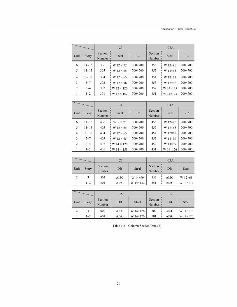
C3 C3A
Unit Story Section Number
Steel RC Section Number
Steel RC
6 14~15 306 W 12 × 72 700×700 356 W 12×96 700×700
5 11~13 305 W 12 × 65 700×700 355 W 12×65 700×700
4 8~10 304 W 12 × 65 700×700 354 W 12×65 700×700
3 5~7 303 W 12 × 96 700×700 353 W 12×96 700×700
2 3~4 302 W 12 × 120 700×700 352 W 14×145 700×700
1 1~2 301 W 12 × 152 700×700 351 W 14×193 700×700
C4 C4A
Unit Story Section Number
Steel RC Section Number
Steel RC
6 14~15 406 W12 × 96 700×700 456 W 12×96 700×700
5 11~13 405 W 12 × 65 700×700 455 W 12×65 700×700
4 8~10 404 W 12 × 65 700×700 454 W 12×65 700×700
3 5~7 403 W 12 × 65 700×700 453 W 14×99 700×700
2 3~4 402 W 14 × 120 700×700 452 W 14×99 700×700
1 1~2 401 W 14 × 159 700×700 451 W 14×176 700×700
C5 C5A
Unit Story Section Number
DB Steel Section Number
DB Steel
2 3 502 AISC W 14×99 552 AISC W 12×65 1 1~2 501 AISC W 14×132 551 AISC W 14×132
C6 C7
Unit Story Section Number
DB Steel Section Number
DB Steel
2 3 602 AISC W 14×176 702 AISC W 14×1761 1~2 601 AISC W 14×176 701 AISC W 14×176
Table 1.2 Column Section Data (2)
21
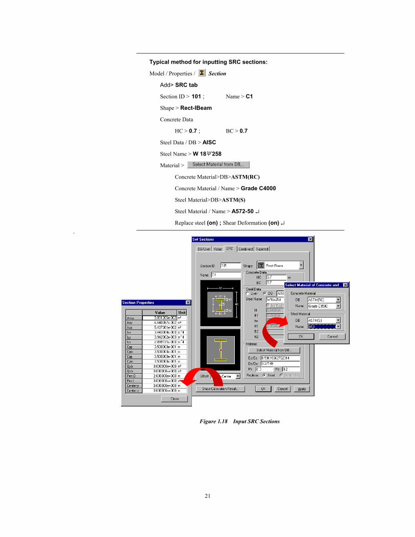
Typical method for inputting SRC sections:
Model / Properties / Section
Add> SRC tab
Section ID > 101 ; Name > C1
Shape > Rect-IBeam
Concrete Data
HC > 0.7 ; BC > 0.7
Steel Data / DB > AISC
Steel Name > W 18×258
Material >
Concrete Material>DB>ASTM(RC)
Concrete Material / Name > Grade C4000
Steel Material>DB>ASTM(S)
Steel Material / Name > A572-50 ↵
Replace steel (on) ; Shear Deformation (on) ↵ .
Figure 1.18 Input SRC Sections
Application 1. Steel Structure
22
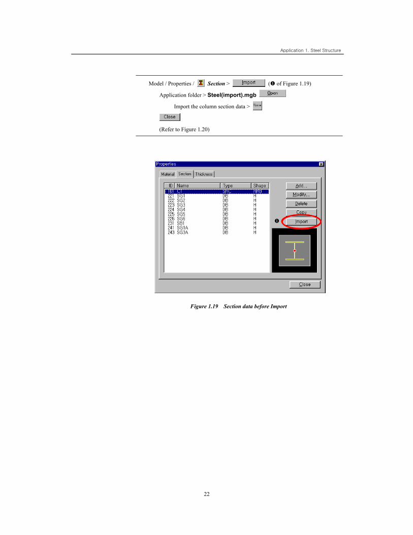
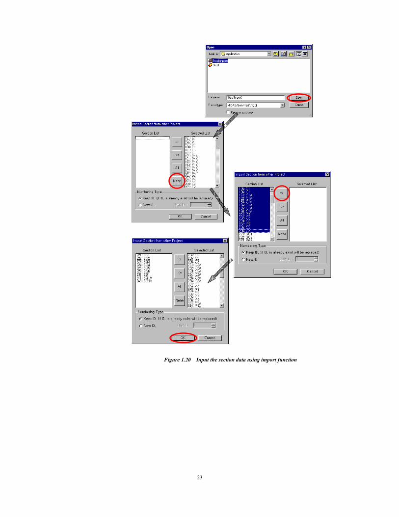
Model / Properties / Section > ( of Figure 1.19)
Application folder > Steel(import).mgb
Import the column section data >
(Refer to Figure 1.20)
Figure 1.19 Section data before Import
23
Figure 1.20 Input the section data using import function
Application 1. Steel Structure
24
Input Columns
Redraw
Node Number (on)
Display > Property > Property Name (off) ↵
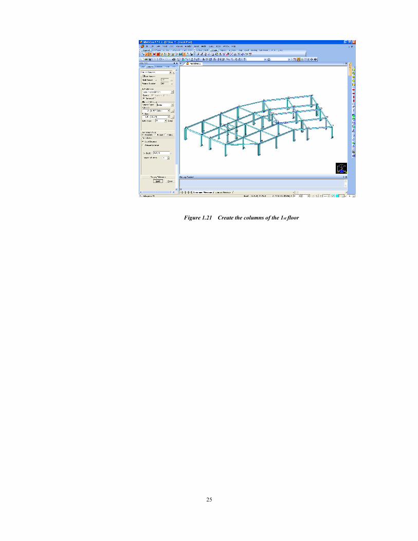
Iso View, Rotate Dynamic Zoom Fit (Refer to Figure 1.21)
Select All
Unselect Window (Node 23, 24)
Model / Elements / Extrude Elements
Extrude Type > Node → Line Element
Reverse I-J (on) ; Element Type > Beam
Material > 3 : SRC Column ; Section > 101 : C1
Generation Type > Translate ; Translate > Equal Distance
Beta angle > 0 ; Number of Times > 1
dx, dy, dz > 0, 0, -6 ↵
Display > Element > Local Direction (on) ↵
Display > Element > Local Direction (off) ↵
25
Figure 1.21 Create the columns of the 1st floor
Application 1. Steel Structure
26
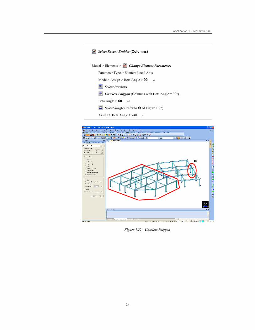
Select Recent Entities (Columns)
Model > Elements > Change Element Parameters
Parameter Type > Element Local Axis
Mode > Assign > Beta Angle > 90 ↵
Select Previous
Unselect Polygon (Columns with Beta Angle = 90°)
Beta Angle > 60 ↵
Select Single (Refer to of Figure 1.22)
Assign > Beta Angle > -30 ↵
Figure 1.22 Unselect Polygon
27
Status bar > Filter > z (Columns)
Select All
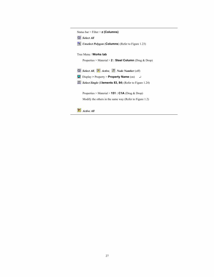
Unselect Polygon (Columns) (Refer to Figure 1.23)
Tree Menu / Works tab
Properties > Material > 2 : Steel Column (Drag & Drop)
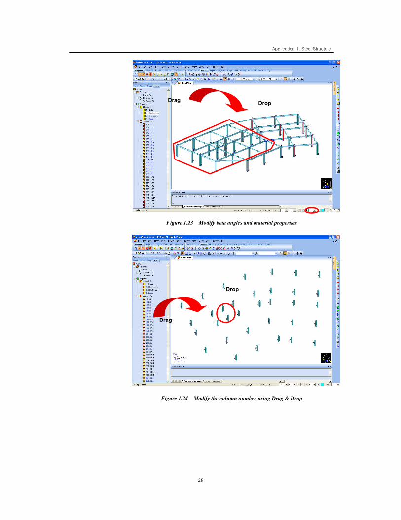
Select All, Active, Node Number (off)
Display > Property > Property Name (on) ↵
Select Single (Elements 83, 84) (Refer to Figure 1.24)
Properties > Material > 151 : C1A (Drag & Drop)
Modify the others in the same way (Refer to Figure 1.2)
Active All
Application 1. Steel Structure
28
Figure 1.23 Modify beta angles and material properties
Figure 1.24 Modify the column number using Drag & Drop
Drag Drop
Drop
Drag
29
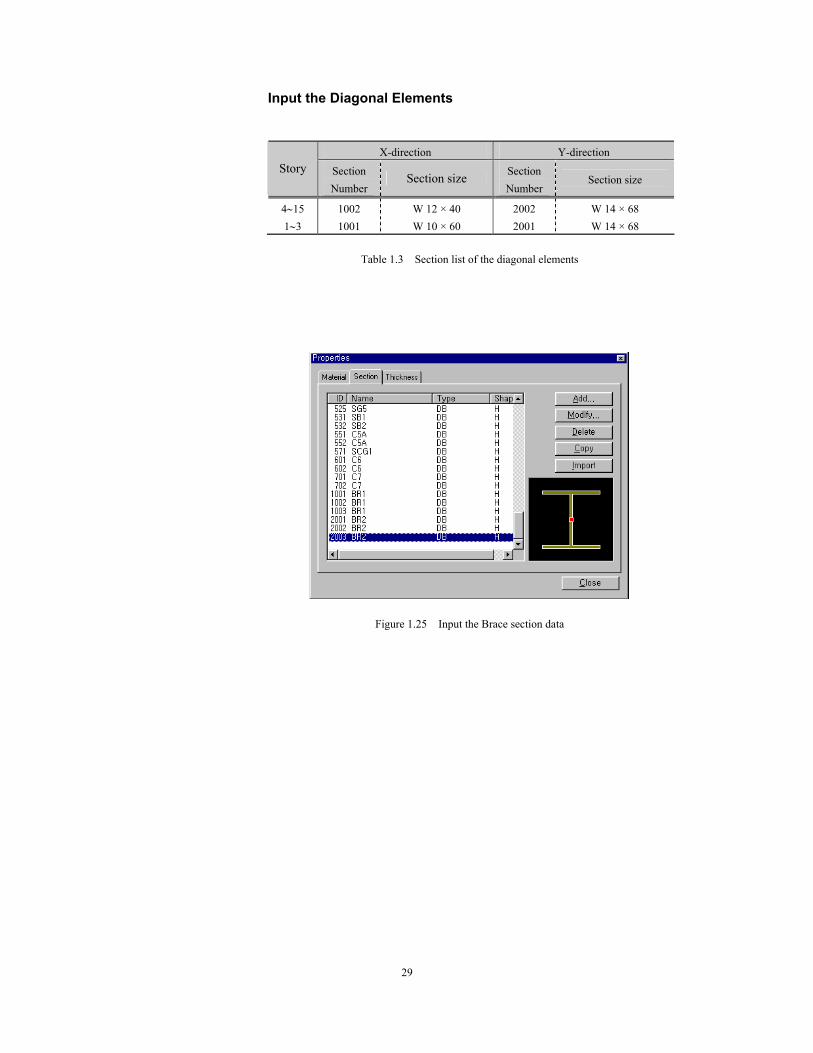
Input the Diagonal Elements
X-direction Y-direction Story Section
Number Section size Section
Number Section size
4∼15 1002 W 12 × 40 2002 W 14 × 68 1∼3 1001 W 10 × 60 2001 W 14 × 68
Table 1.3 Section list of the diagonal elements
Figure 1.25 Input the Brace section data
Application 1. Steel Structure
30
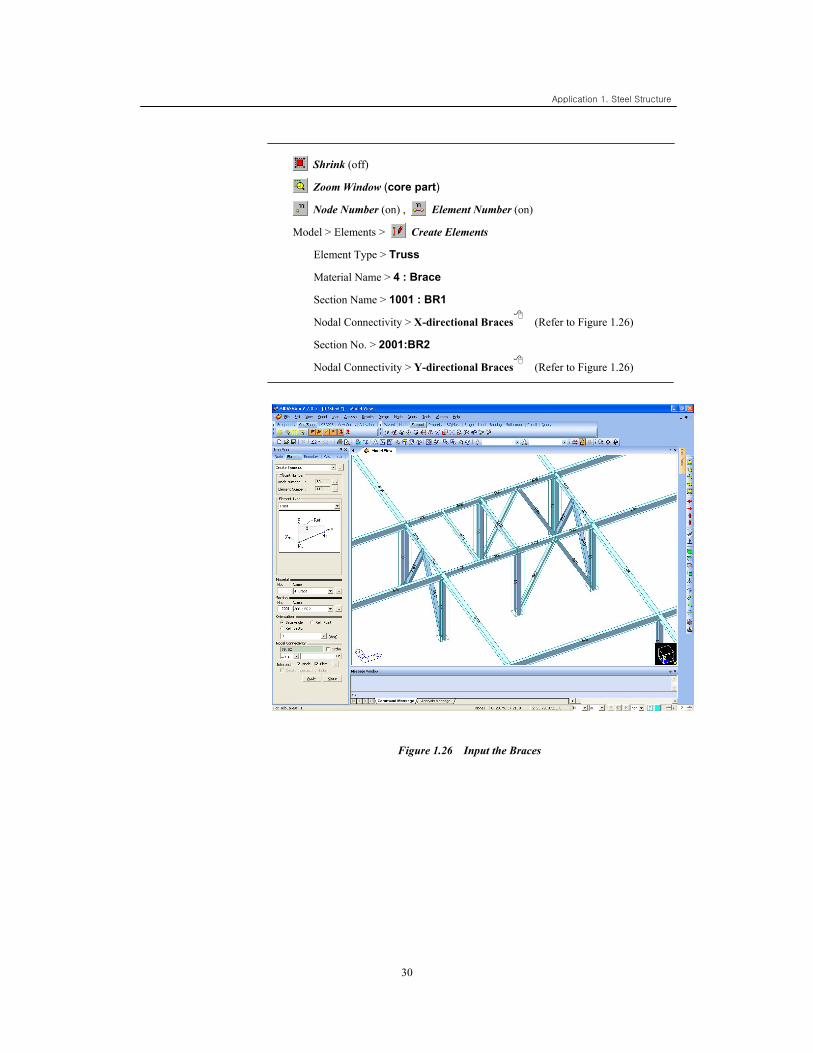
Shrink (off)
Zoom Window (core part)
Node Number (on) , Element Number (on)
Model > Elements > Create Elements
Element Type > Truss
Material Name > 4 : Brace
Section Name > 1001 : BR1
Nodal Connectivity > X-directional Braces (Refer to Figure 1.26)
Section No. > 2001:BR2
Nodal Connectivity > Y-directional Braces (Refer to Figure 1.26)
Figure 1.26 Input the Braces
31
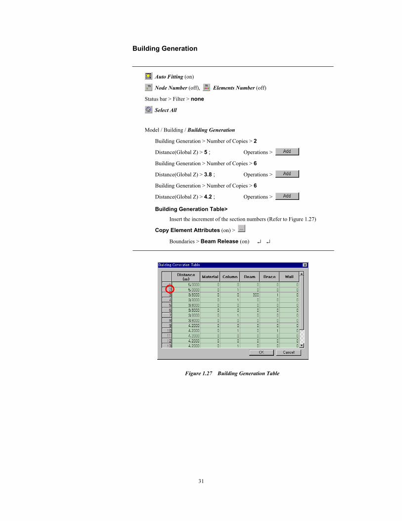
Building Generation
Auto Fitting (on)
Node Number (off), Elements Number (off)
Status bar > Filter > none
Select All
Model / Building / Building Generation
Building Generation > Number of Copies > 2
Distance(Global Z) > 5 ; Operations >
Building Generation > Number of Copies > 6
Distance(Global Z) > 3.8 ; Operations >
Building Generation > Number of Copies > 6
Distance(Global Z) > 4.2 ; Operations >
Building Generation Table>
Insert the increment of the section numbers (Refer to Figure 1.27)
Copy Element Attributes (on) >
Boundaries > Beam Release (on) ↵ ↵
Figure 1.27 Building Generation Table
Application 1. Steel Structure
32
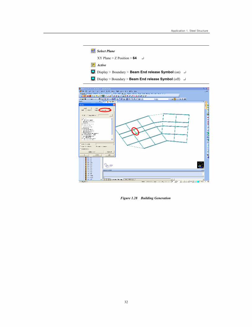
Select Plane
XY Plane > Z Position > 64 ↵
Active
Display > Boundary > Beam End release Symbol (on) ↵
Display > Boundary > Beam End release Symbol (off) ↵
Figure 1.28 Building Generation
33
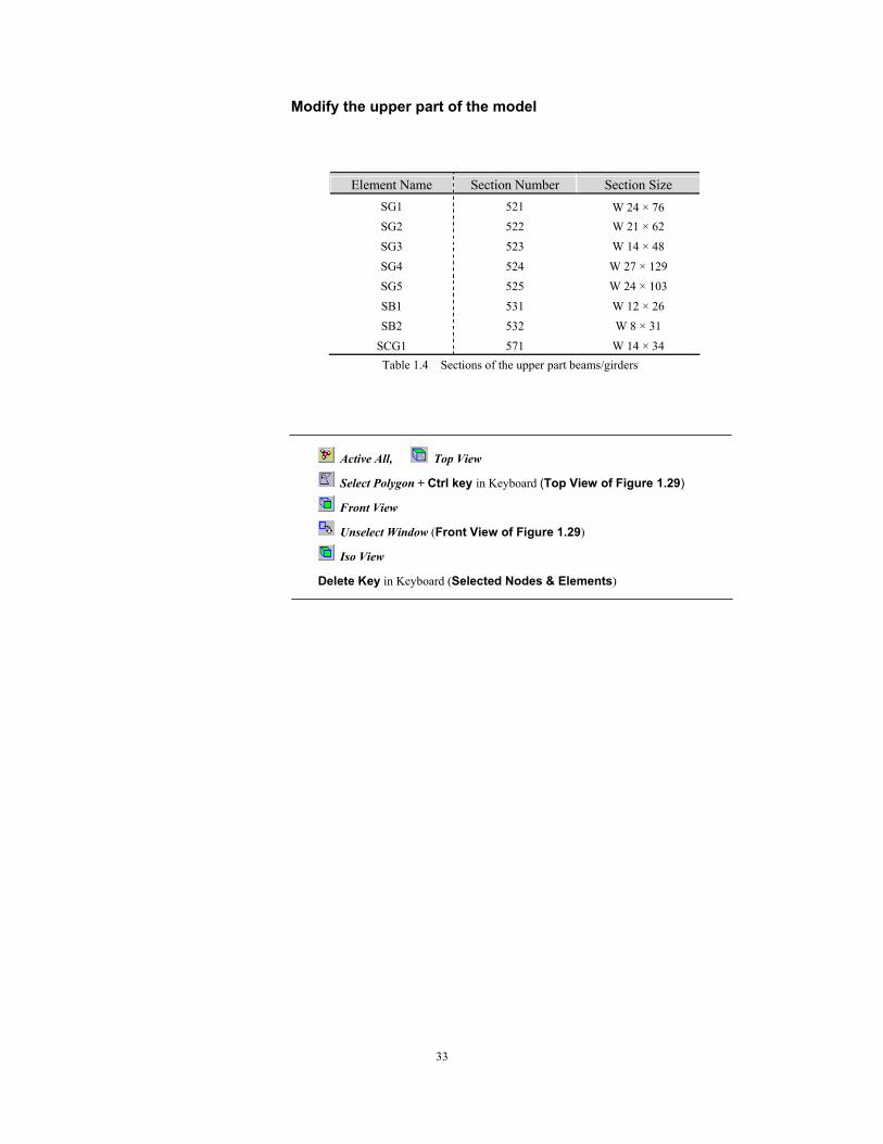
Modify the upper part of the model
Element Name Section Number Section Size SG1 521 W 24 × 76 SG2 522 W 21 × 62 SG3 523 W 14 × 48 SG4 524 W 27 × 129 SG5 525 W 24 × 103 SB1 531 W 12 × 26 SB2 532 W 8 × 31
SCG1 571 W 14 × 34 Table 1.4 Sections of the upper part beams/girders
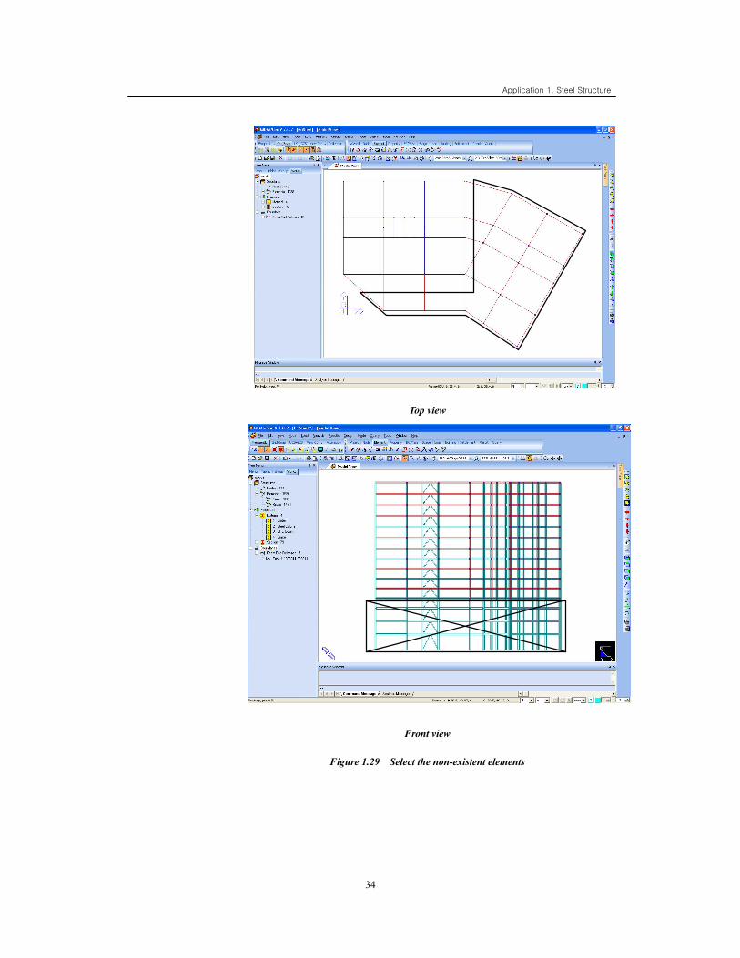
Active All, Top View
Select Polygon + Ctrl key in Keyboard (Top View of Figure 1.29)
Front View
Unselect Window (Front View of Figure 1.29)
Iso View
Delete Key in Keyboard (Selected Nodes & Elements)
Application 1. Steel Structure
34
Top view
Front view
Figure 1.29 Select the non-existent elements
35
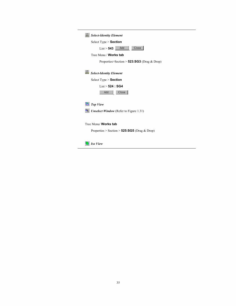
Select-Identity Element
Select Type > Section
List > 543 ,
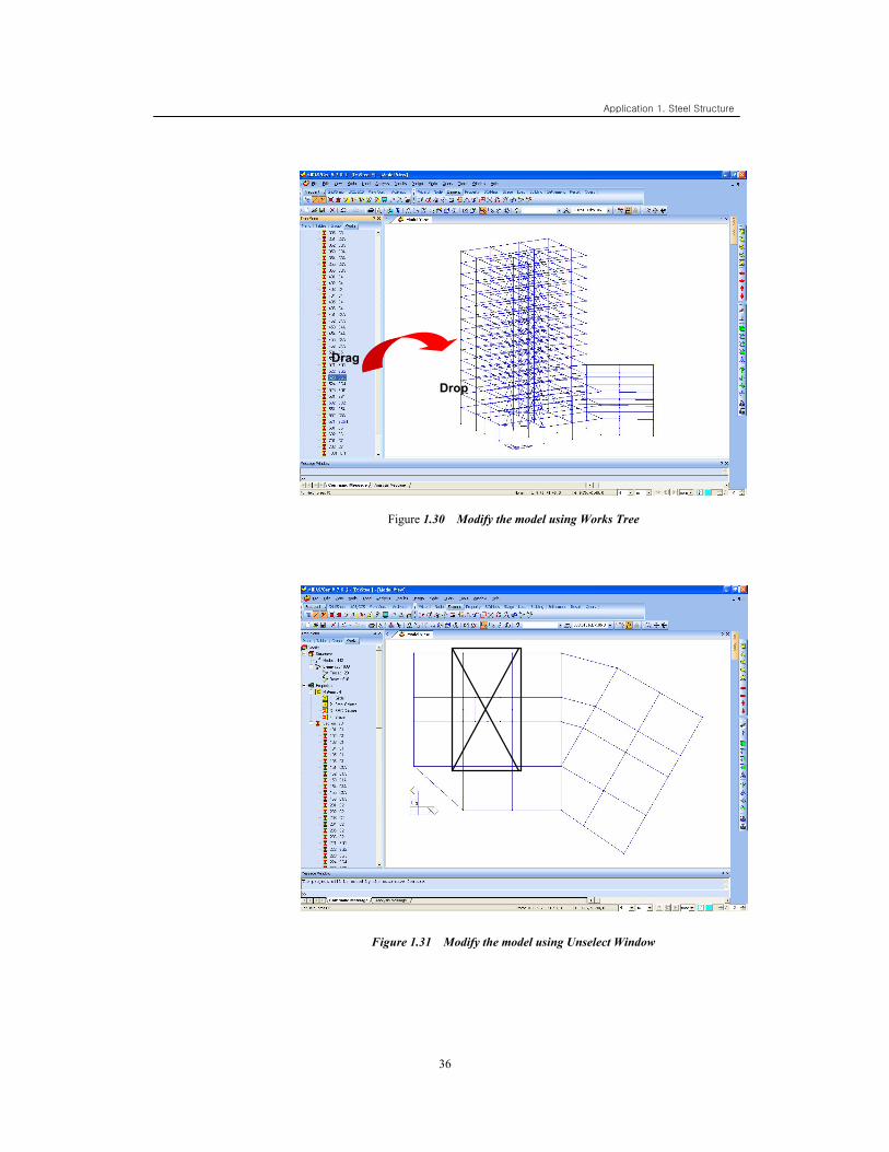
Tree Menu / Works tab
Properties>Section > 523:SG3 (Drag & Drop)
Select-Identity Element
Select Type > Section
List > 524 : SG4
,
Top View
Unselect Window (Refer to Figure 1.31)
Tree Menu/ Works tab
Properties > Section > 525:SG5 (Drag & Drop)
Iso View
Application 1. Steel Structure
36
Figure 1.30 Modify the model using Works Tree
Figure 1.31 Modify the model using Unselect Window
Drag
Drop
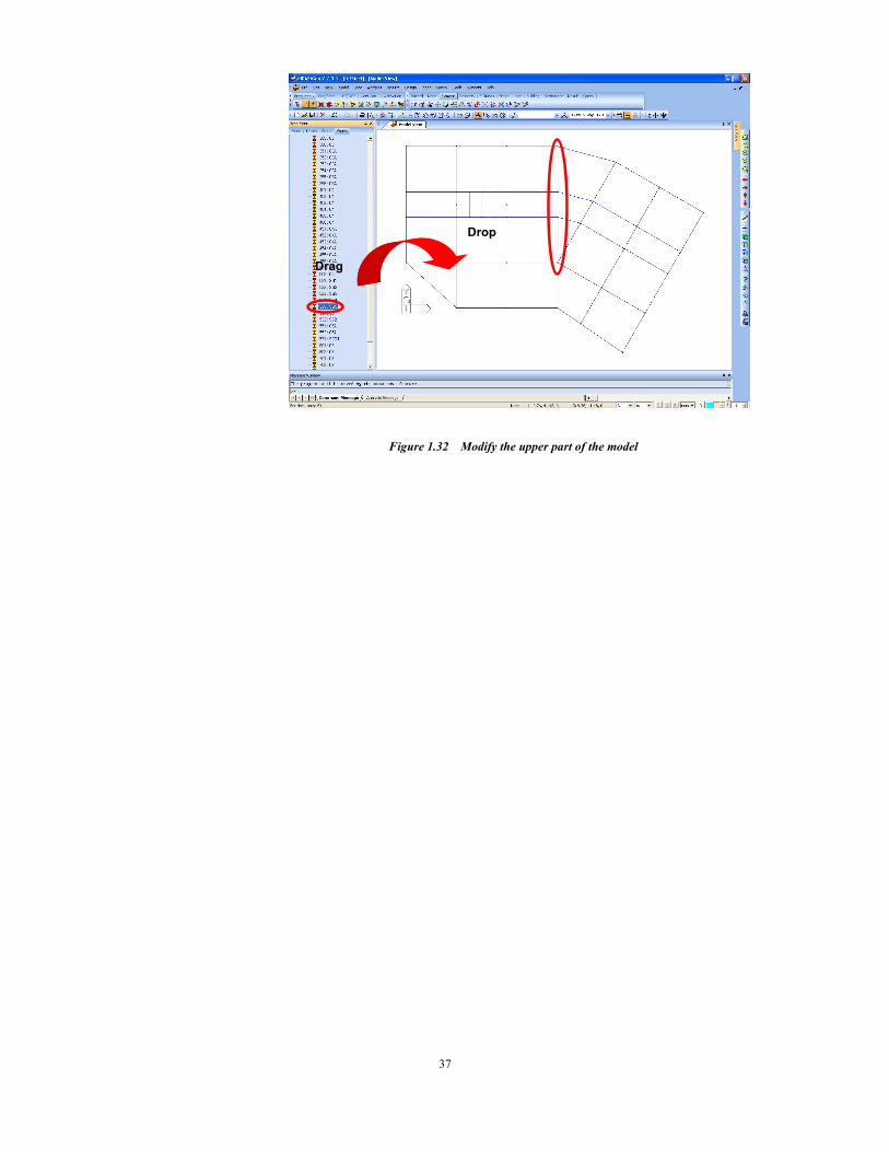
37
Figure 1.32 Modify the upper part of the model
Drag
Drop
Application 1. Steel Structure
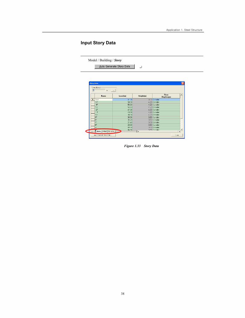
38
Input Story Data
Model / Building / Story
↵
Figure 1.33 Story Data
39
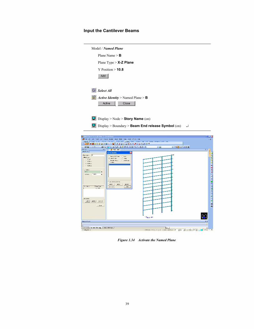
Input the Cantilever Beams
Model / Named Plane
Plane Name > B
Plane Type > X-Z Plane
Y Position > 10.8
Select All
Active Identity > Named Plane > B
,
Display > Node > Story Name (on)
Display > Boundary > Beam End release Symbol (on) ↵
Figure 1.34 Activate the Named Plane
Application 1. Steel Structure
40
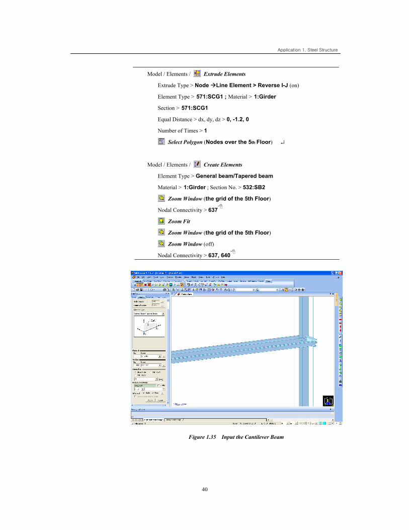
Model / Elements / Extrude Elements
Extrude Type > Node Line Element > Reverse I-J (on)
Element Type > 571:SCG1 ; Material > 1:Girder
Section > 571:SCG1
Equal Distance > dx, dy, dz > 0, -1.2, 0
Number of Times > 1
Select Polygon (Nodes over the 5th Floor) ↵
Model / Elements / Create Elements
Element Type > General beam/Tapered beam
Material > 1:Girder ; Section No. > 532:SB2
Zoom Window (the grid of the 5th Floor)
Nodal Connectivity > 637
Zoom Fit
Zoom Window (the grid of the 5th Floor)
Zoom Window (off)
Nodal Connectivity > 637, 640
Figure 1.35 Input the Cantilever Beam
41
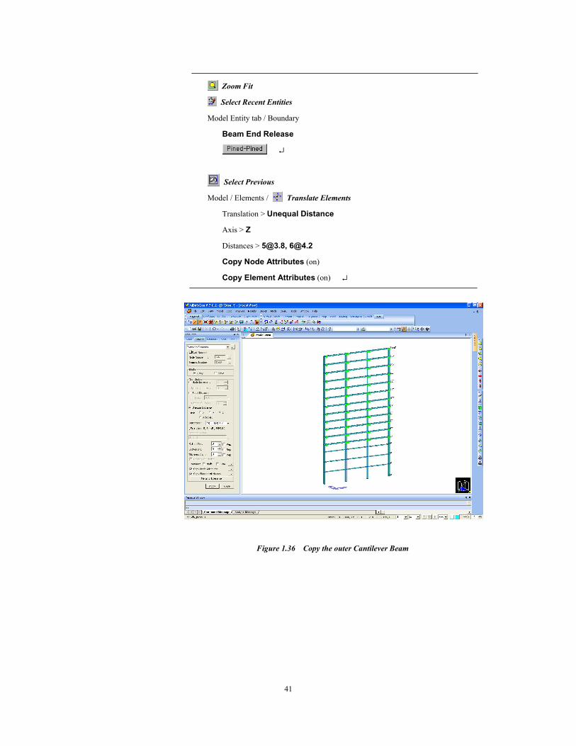
Zoom Fit
Select Recent Entities
Model Entity tab / Boundary
Beam End Release
↵
Select Previous
Model / Elements / Translate Elements
Translation > Unequal Distance
Axis > Z
Distances > [email protected], [email protected]
Copy Node Attributes (on)
Copy Element Attributes (on) ↵
Figure 1.36 Copy the outer Cantilever Beam
Application 1. Steel Structure
42
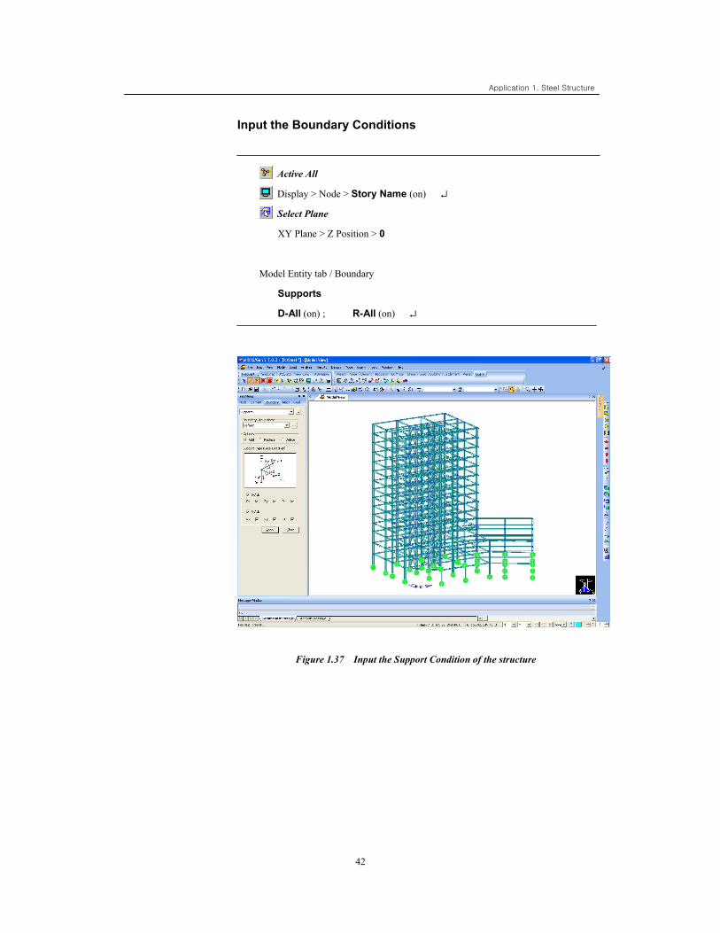
Input the Boundary Conditions
Active All
Display > Node > Story Name (on) ↵
Select Plane
XY Plane > Z Position > 0
Model Entity tab / Boundary
Supports
D-All (on) ; R-All (on) ↵
Figure 1.37 Input the Support Condition of the structure
Application 1. Steel Structure
43
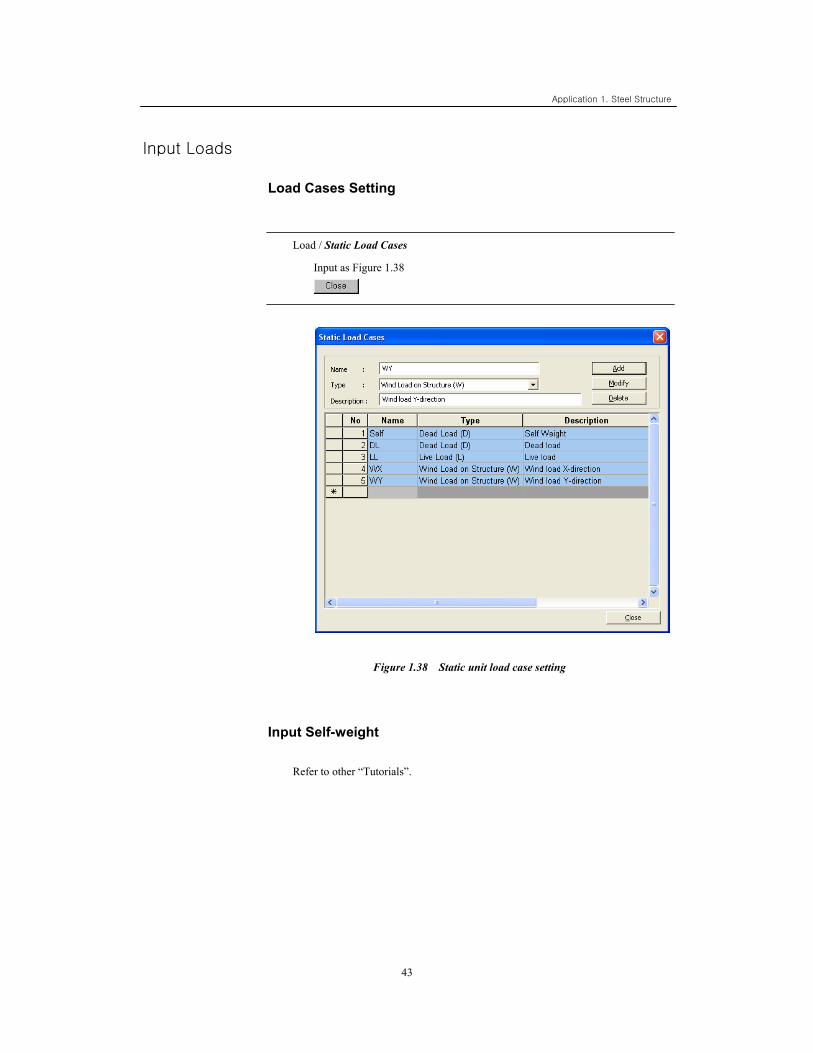
Input Loads
Load Cases Setting
Load / Static Load Cases
Input as Figure 1.38
Figure 1.38 Static unit load case setting
Input Self-weight
Refer to other “Tutorials”.
Application 1. Steel Structure
44
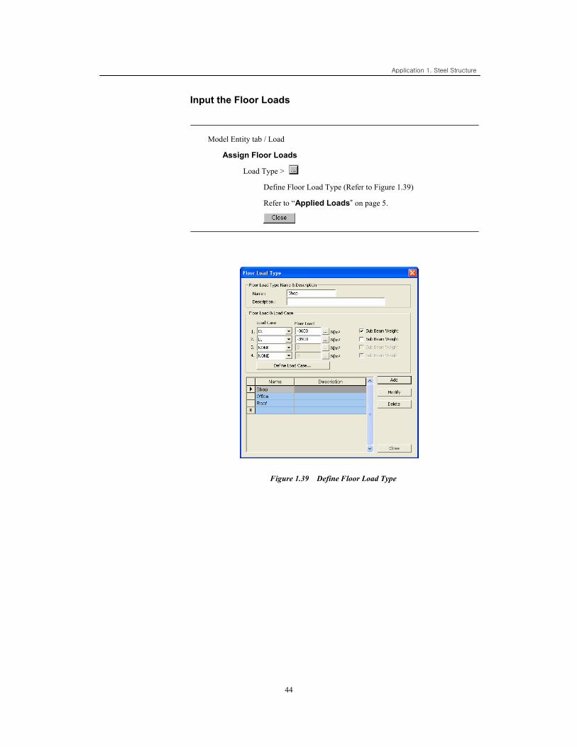
Input the Floor Loads
Model Entity tab / Load
Assign Floor Loads
Load Type >
Define Floor Load Type (Refer to Figure 1.39)
Refer to “Applied Loads” on page 5.
Figure 1.39 Define Floor Load Type
Application 1. Steel Structure
45
Active Identity
Story > 2F +Below (on)
,
Node Number (on)
Hidden (off)
Angle View
Horizontal > 50 ; Vertical > 60 ↵
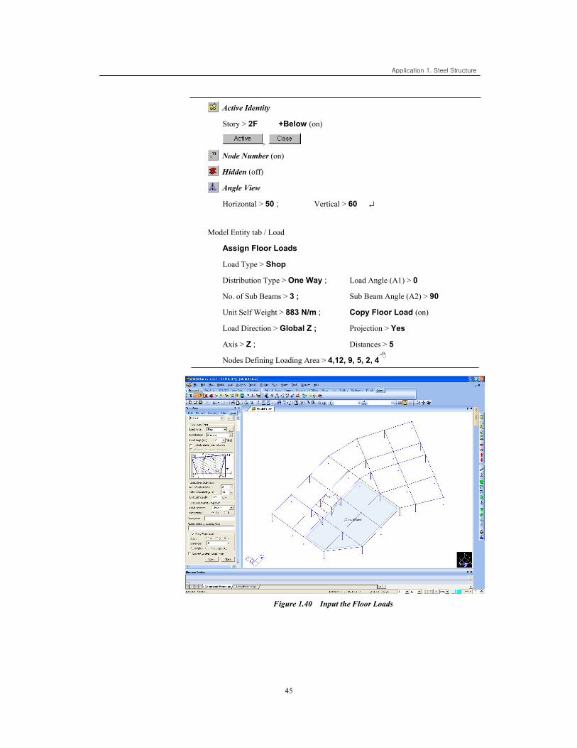
Model Entity tab / Load
Assign Floor Loads
Load Type > Shop
Distribution Type > One Way ; Load Angle (A1) > 0
No. of Sub Beams > 3 ; Sub Beam Angle (A2) > 90
Unit Self Weight > 883 N/m ; Copy Floor Load (on)
Load Direction > Global Z ; Projection > Yes
Axis > Z ; Distances > 5
Nodes Defining Loading Area > 4,12, 9, 5, 2, 4
Figure 1.40 Input the Floor Loads
Application 1. Steel Structure
46
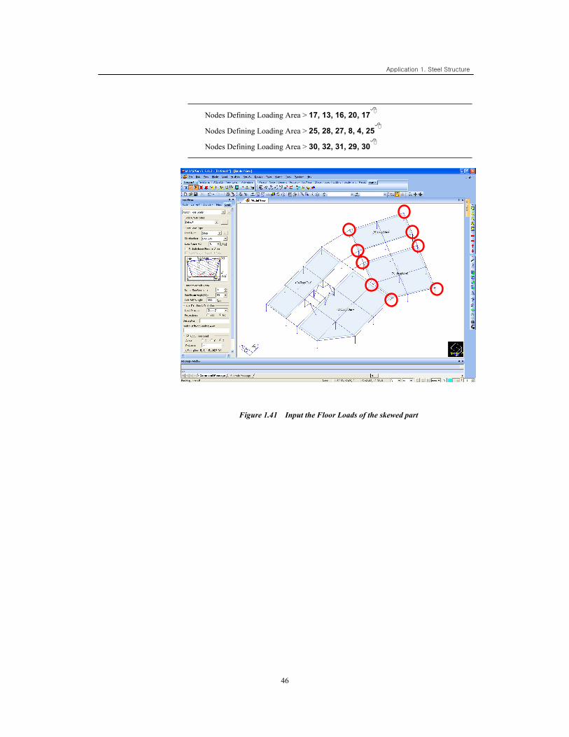
Nodes Defining Loading Area > 17, 13, 16, 20, 17
Nodes Defining Loading Area > 25, 28, 27, 8, 4, 25
Nodes Defining Loading Area > 30, 32, 31, 29, 30
Figure 1.41 Input the Floor Loads of the skewed part
Application 1. Steel Structure
47
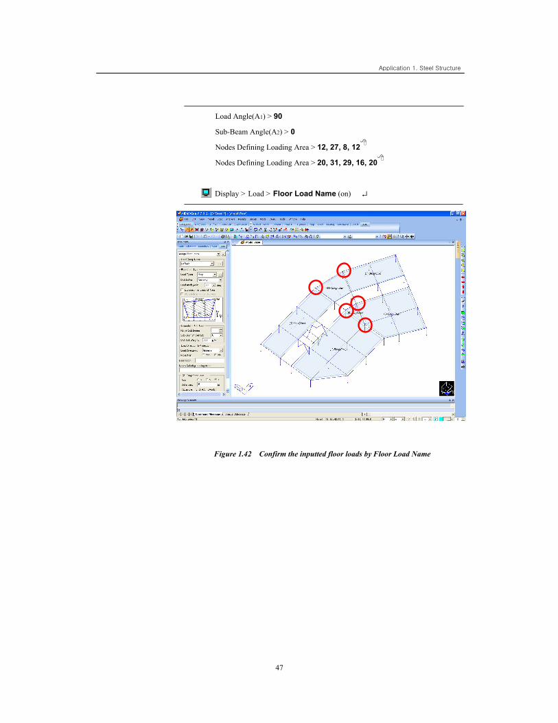
Load Angle(A1) > 90
Sub-Beam Angle(A2) > 0
Nodes Defining Loading Area > 12, 27, 8, 12
Nodes Defining Loading Area > 20, 31, 29, 16, 20
Display > Load > Floor Load Name (on) ↵
Figure 1.42 Confirm the inputted floor loads by Floor Load Name
Application 1. Steel Structure
48
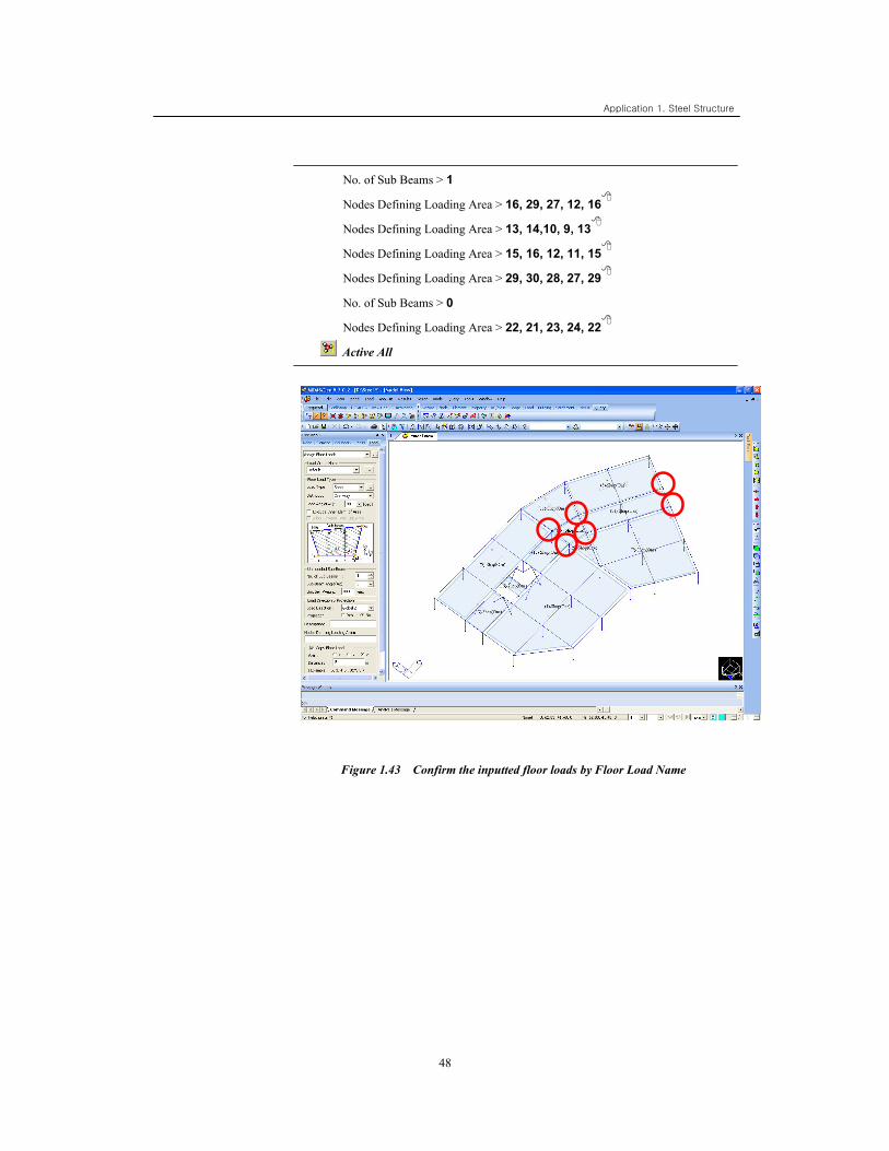
No. of Sub Beams > 1
Nodes Defining Loading Area > 16, 29, 27, 12, 16
Nodes Defining Loading Area > 13, 14,10, 9, 13
Nodes Defining Loading Area > 15, 16, 12, 11, 15
Nodes Defining Loading Area > 29, 30, 28, 27, 29
No. of Sub Beams > 0
Nodes Defining Loading Area > 22, 21, 23, 24, 22
Active All
Figure 1.43 Confirm the inputted floor loads by Floor Load Name
Application 1. Steel Structure
49
Active Identity
Story > 4F +Below (on)
,
Display > Load > Floor Load Name (off) ↵
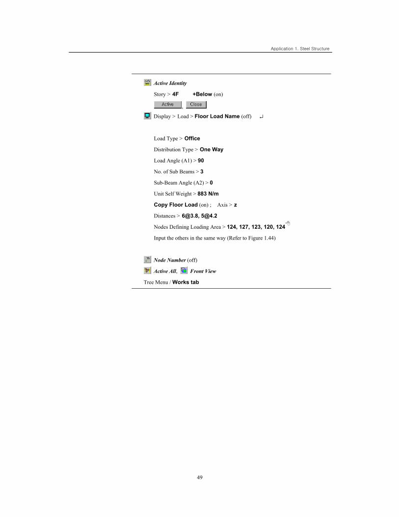
Load Type > Office
Distribution Type > One Way
Load Angle (A1) > 90
No. of Sub Beams > 3
Sub-Beam Angle (A2) > 0
Unit Self Weight > 883 N/m
Copy Floor Load (on) ; Axis > z
Distances > [email protected], [email protected]
Nodes Defining Loading Area > 124, 127, 123, 120, 124
Input the others in the same way (Refer to Figure 1.44)
Node Number (off)
Active All, Front View
Tree Menu / Works tab
Application 1. Steel Structure
50
Figure 1.44 Loading Plan of the upper part over the 4th floor
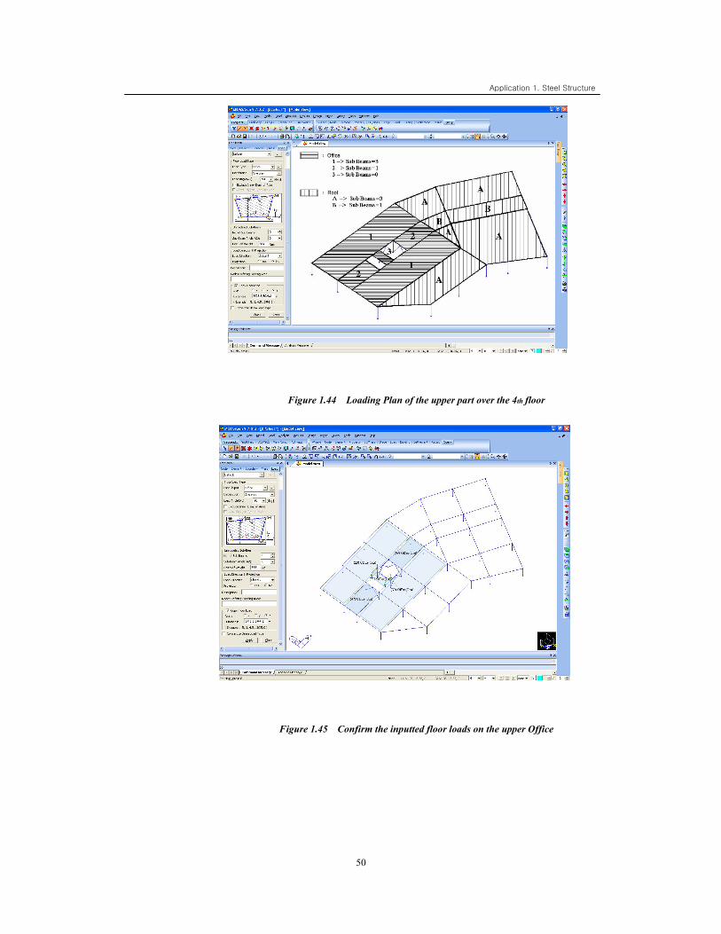
Figure 1.45 Confirm the inputted floor loads on the upper Office
Application 1. Steel Structure
51
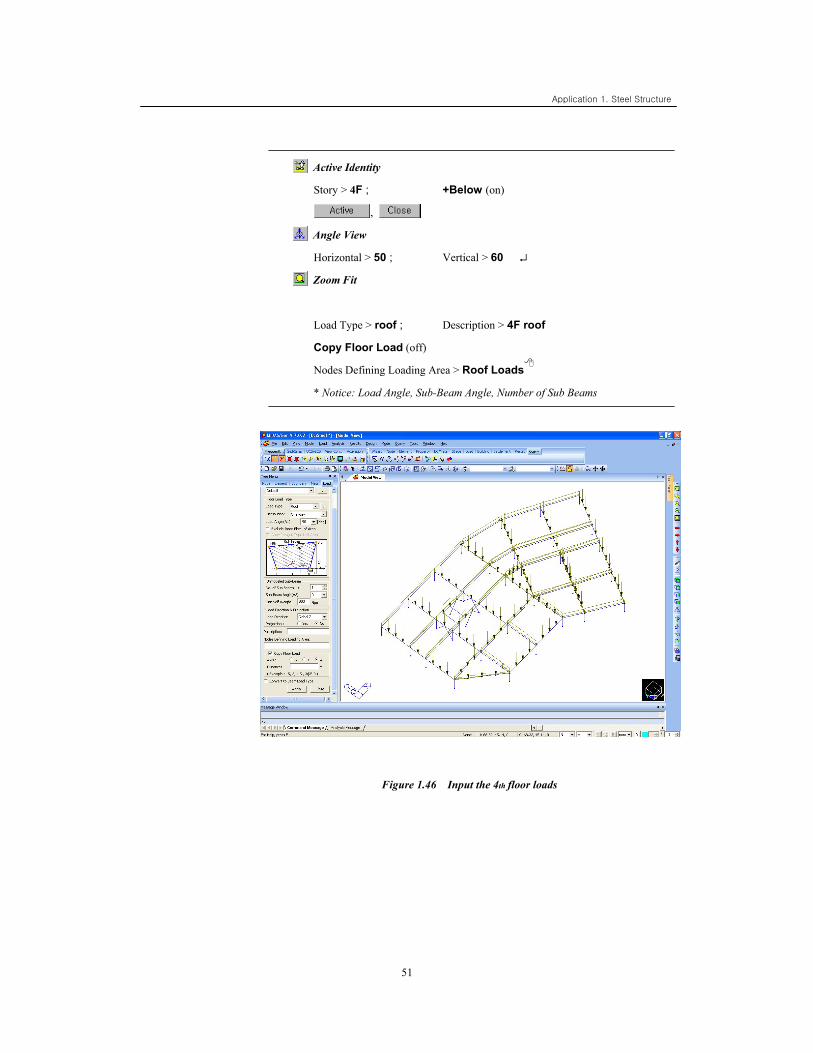
Active Identity
Story > 4F ; +Below (on)
,
Angle View
Horizontal > 50 ; Vertical > 60 ↵
Zoom Fit
Load Type > roof ; Description > 4F roof
Copy Floor Load (off)
Nodes Defining Loading Area > Roof Loads
* Notice: Load Angle, Sub-Beam Angle, Number of Sub Beams
Figure 1.46 Input the 4th floor loads
Application 1. Steel Structure
52
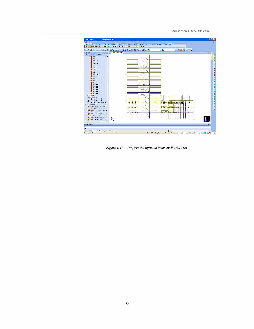
Figure 1.47 Confirm the inputted loads by Works Tree
Application 1. Steel Structure
53
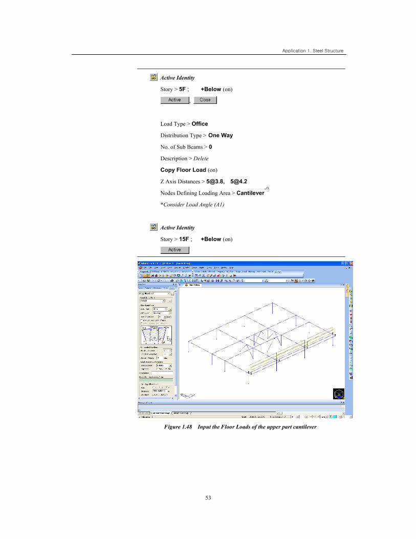
Active Identity
Story > 5F ; +Below (on)
,
Load Type > Office
Distribution Type > One Way
No. of Sub Beams > 0
Description > Delete
Copy Floor Load (on)
Z Axis Distances > [email protected], [email protected]
Nodes Defining Loading Area > Cantilever
*Consider Load Angle (A1)
Active Identity
Story > 15F ; +Below (on)
Figure 1.48 Input the Floor Loads of the upper part cantilever
Application 1. Steel Structure
54
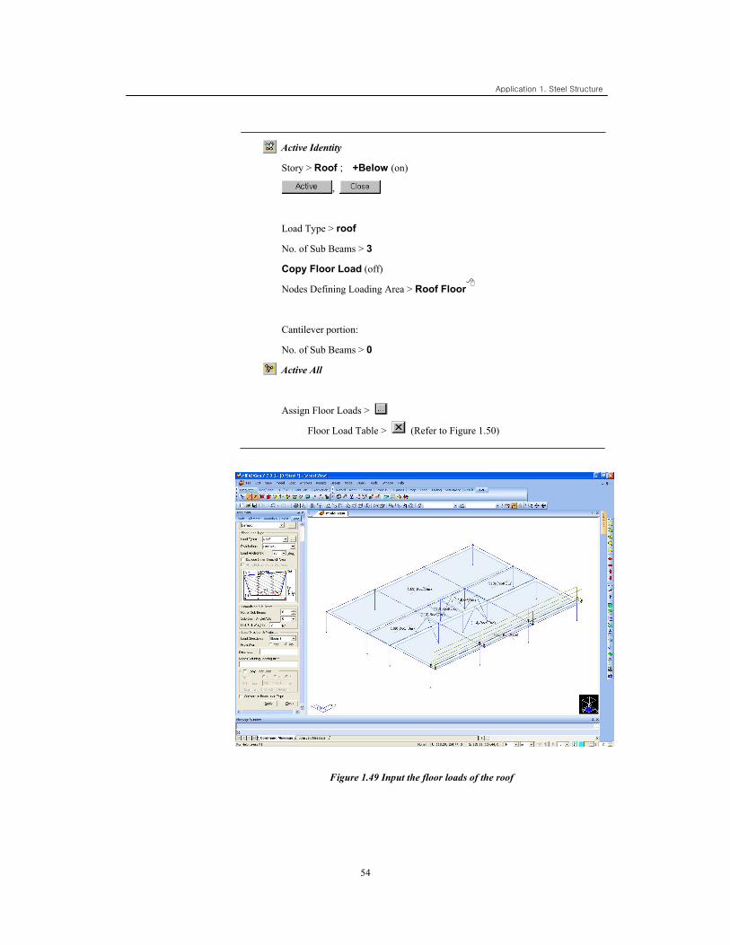
Active Identity
Story > Roof ; +Below (on)
,
Load Type > roof
No. of Sub Beams > 3
Copy Floor Load (off)
Nodes Defining Loading Area > Roof Floor
Cantilever portion:
No. of Sub Beams > 0
Active All
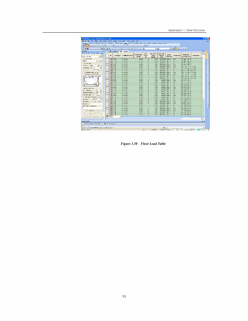
Assign Floor Loads >
Floor Load Table > (Refer to Figure 1.50)
Figure 1.49 Input the floor loads of the roof
Application 1. Steel Structure
55
Figure 1.50 Floor Load Table
Application 1. Steel Structure
56
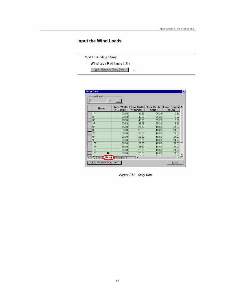
Input the Wind Loads
Model / Building / Story
Wind tab ( of Figure 1.51)
↵
Figure 1.51 Story Data
Application 1. Steel Structure
57
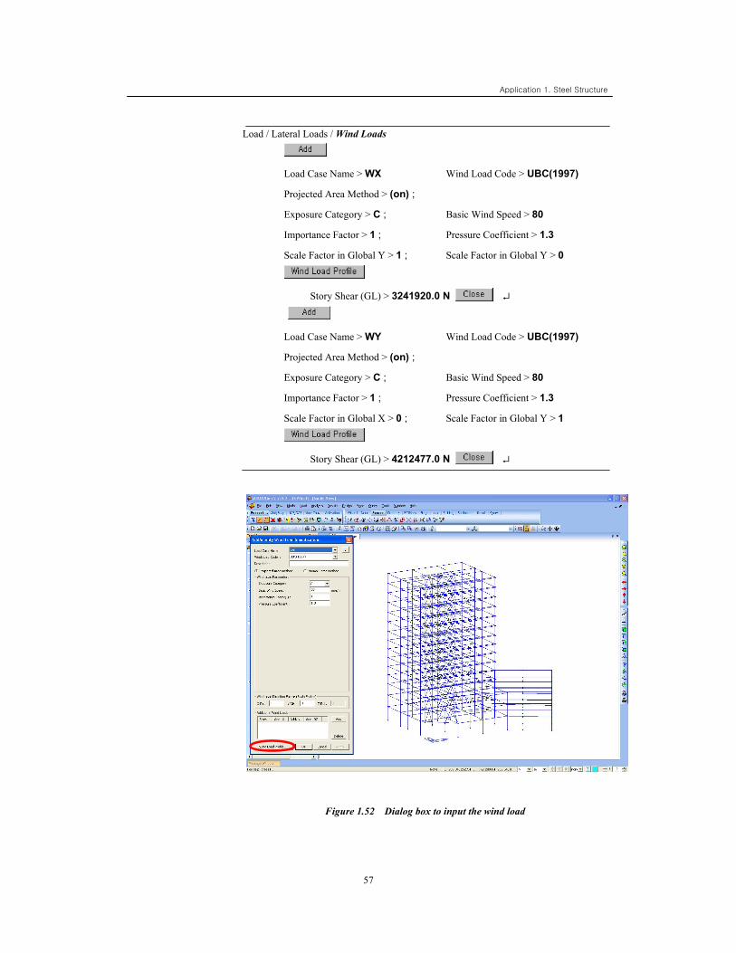
Load / Lateral Loads / Wind Loads
Load Case Name > WX Wind Load Code > UBC(1997)
Projected Area Method > (on) ;
Exposure Category > C ; Basic Wind Speed > 80
Importance Factor > 1 ; Pressure Coefficient > 1.3
Scale Factor in Global Y > 1 ; Scale Factor in Global Y > 0
Story Shear (GL) > 3241920.0 N ↵
Load Case Name > WY Wind Load Code > UBC(1997)
Projected Area Method > (on) ;
Exposure Category > C ; Basic Wind Speed > 80
Importance Factor > 1 ; Pressure Coefficient > 1.3
Scale Factor in Global X > 0 ; Scale Factor in Global Y > 1
Story Shear (GL) > 4212477.0 N ↵
Figure 1.52 Dialog box to input the wind load
Application 1. Steel Structure
58
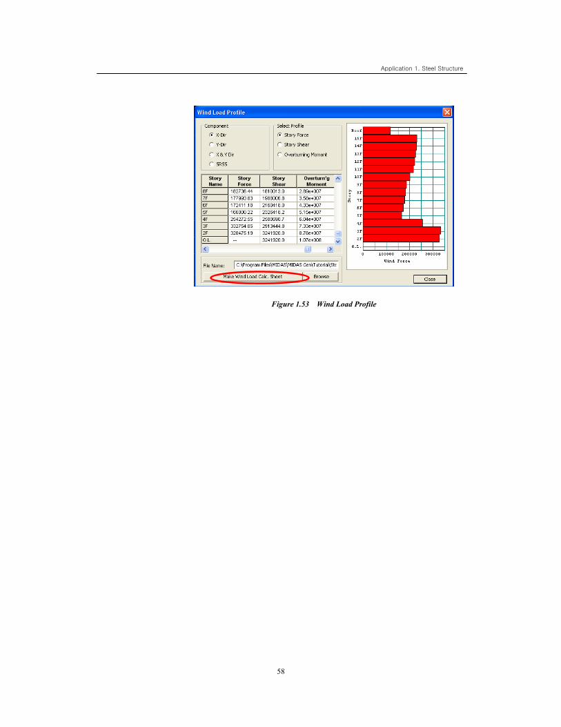
Figure 1.53 Wind Load Profile
Application 1. Steel Structure
59
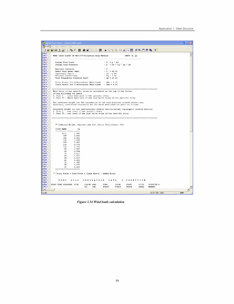
Figure 1.54 Wind loads calculation
Application 1. Steel Structure
60
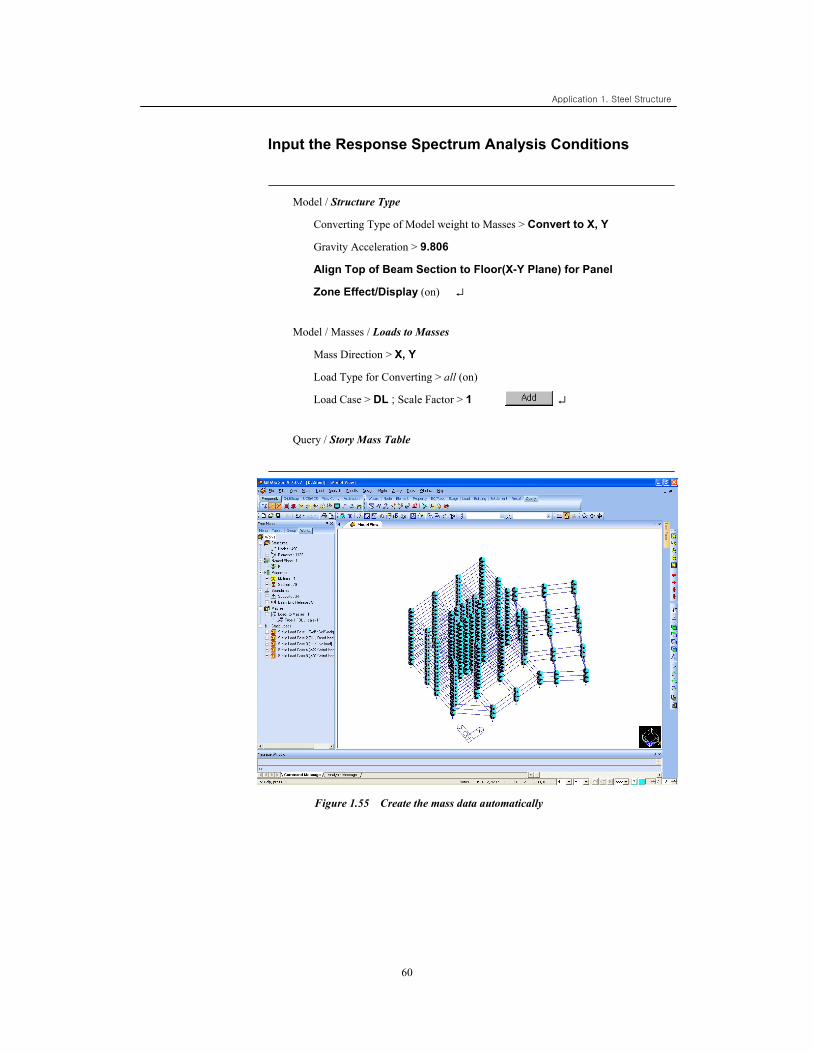
Input the Response Spectrum Analysis Conditions
Model / Structure Type
Converting Type of Model weight to Masses > Convert to X, Y
Gravity Acceleration > 9.806
Align Top of Beam Section to Floor(X-Y Plane) for Panel
Zone Effect/Display (on) ↵
Model / Masses / Loads to Masses
Mass Direction > X, Y
Load Type for Converting > all (on)
Load Case > DL ; Scale Factor > 1 ↵
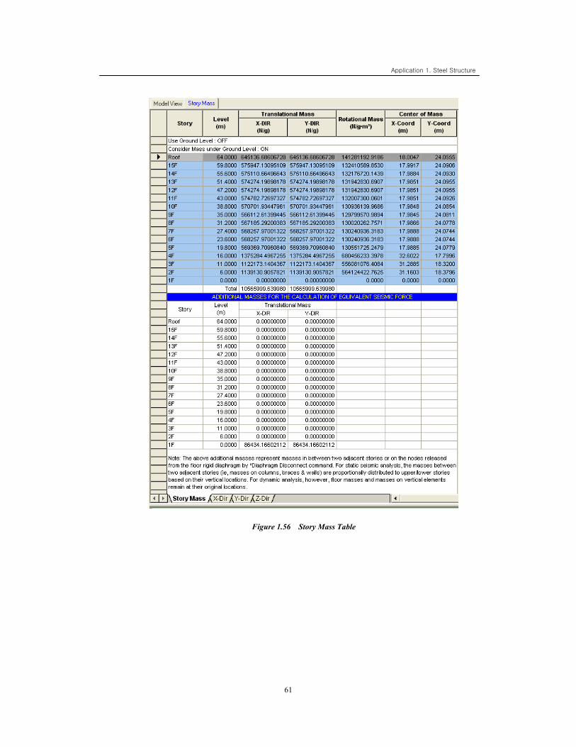
Query / Story Mass Table
Figure 1.55 Create the mass data automatically
Application 1. Steel Structure
61
Figure 1.56 Story Mass Table
Application 1. Steel Structure
62
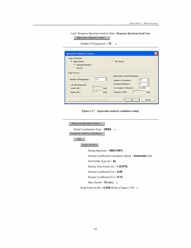
Load / Response Spectrum Analysis Data / Response Spectrum Load Case
Number of Frequencies > 15 ↵
Figure 1.57 Eigenvalue analysis conditions setting
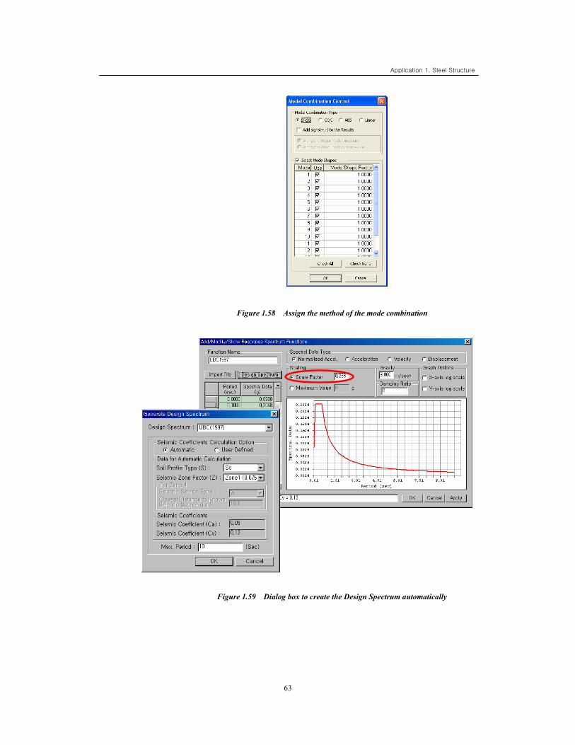
Modal Combination Type > SRSS ↵
Design Spectrum > UBC(1997)
Seismic Coefficients Calculation Option > Automatic (on)
Soil Profile Type (S) > Sc
Seismic Zone Factor (Z) > 1 (0.075)
Seismic Coefficient (Ca) > 0.09
Seismic Coefficient (Cv) > 0.13
Max. Period > 10 (sec) ↵
Scale Factor (IE/R) > 0.238 (Refer to Figure 1.59) ↵
Application 1. Steel Structure
63
Figure 1.58 Assign the method of the mode combination
Figure 1.59 Dialog box to create the Design Spectrum automatically
Application 1. Steel Structure
64
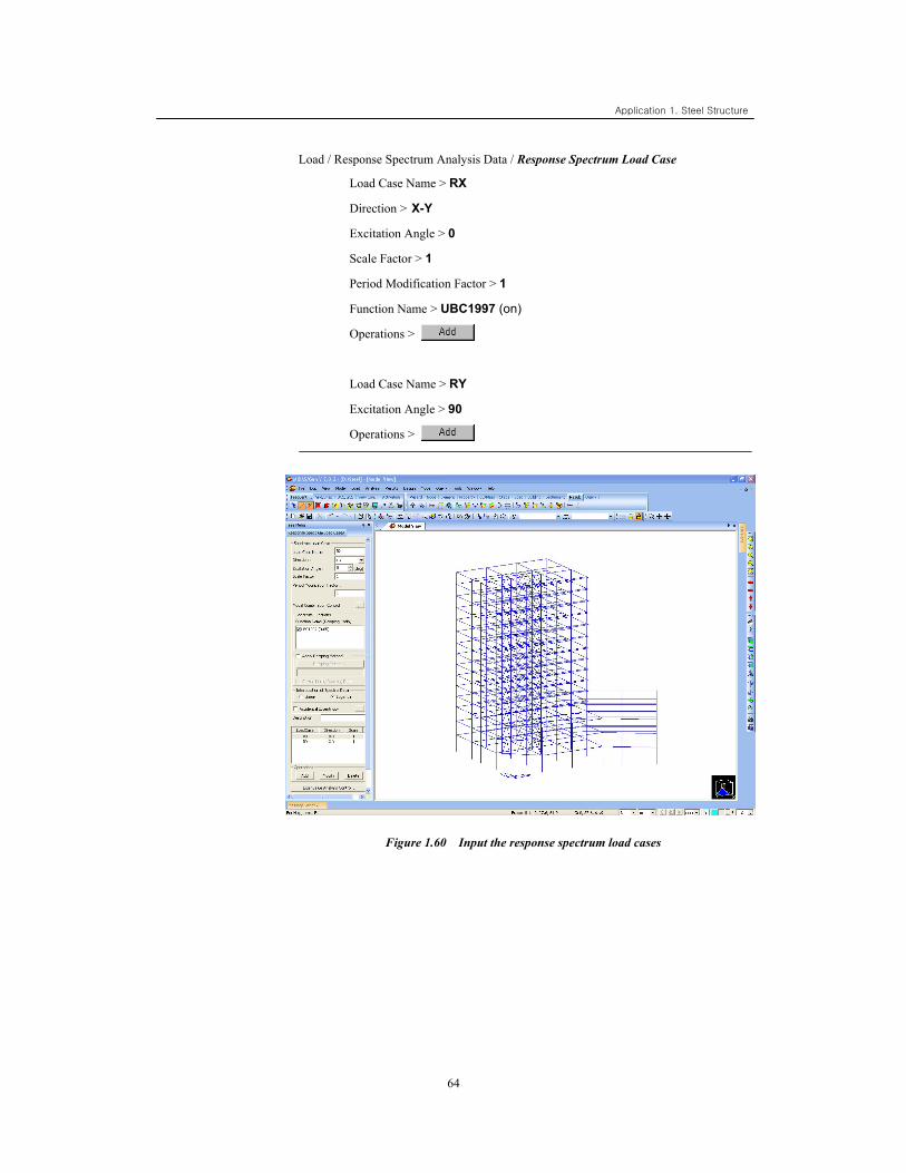
Load / Response Spectrum Analysis Data / Response Spectrum Load Case
Load Case Name > RX
Direction > X-Y
Excitation Angle > 0
Scale Factor > 1
Period Modification Factor > 1
Function Name > UBC1997 (on)
Operations >
Load Case Name > RY
Excitation Angle > 90
Operations >
Figure 1.60 Input the response spectrum load cases
65
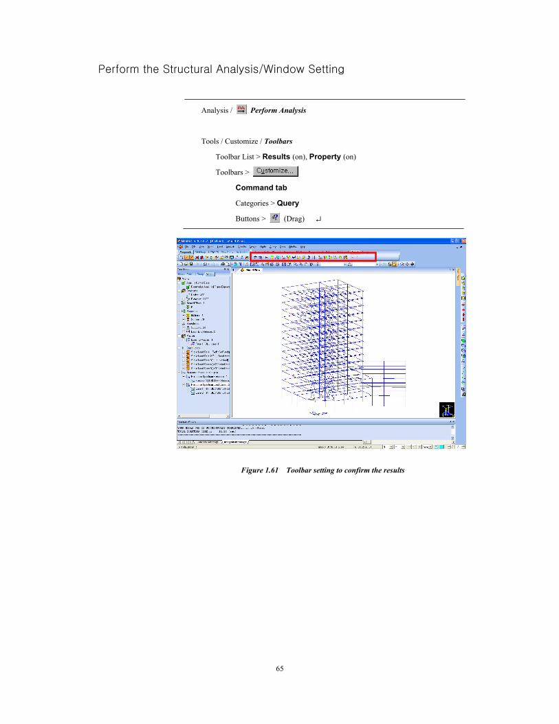
Perform the Structural Analysis/Window Setting
Analysis / Perform Analysis
Tools / Customize / Toolbars
Toolbar List > Results (on), Property (on)
Toolbars >
Command tab
Categories > Query
Buttons > (Drag) ↵
Figure 1.61 Toolbar setting to confirm the results
Application 1. Steel Structure
66
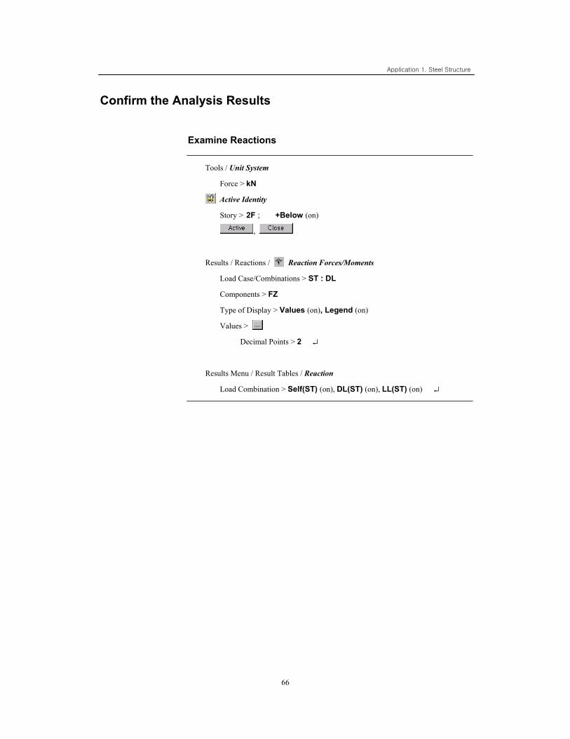
Confirm the Analysis Results
Examine Reactions
Tools / Unit System
Force > kN
Active Identity
Story > 2F ; +Below (on)
,
Results / Reactions / Reaction Forces/Moments
Load Case/Combinations > ST : DL
Components > FZ
Type of Display > Values (on), Legend (on)
Values >
Decimal Points > 2 ↵
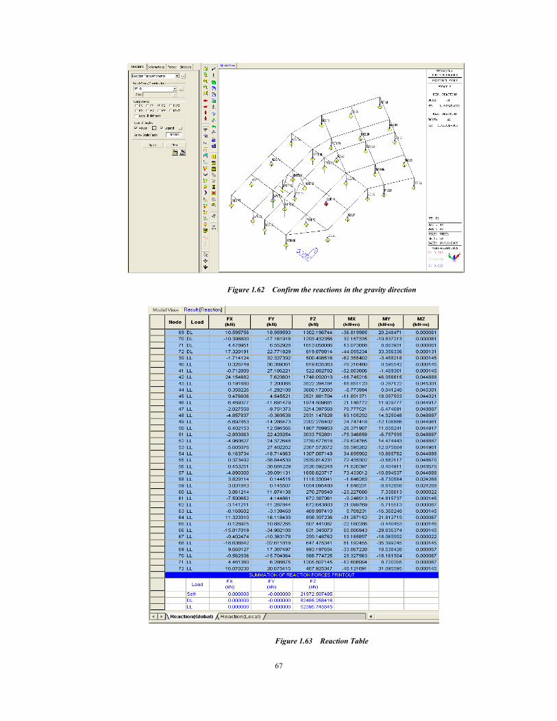
Results Menu / Result Tables / Reaction
Load Combination > Self(ST) (on), DL(ST) (on), LL(ST) (on) ↵
67
Figure 1.62 Confirm the reactions in the gravity direction
Figure 1.63 Reaction Table
Application 1. Steel Structure
68
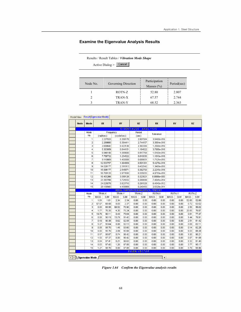
Examine the Eigenvalue Analysis Results
Results / Result Tables / Vibration Mode Shape
Active Dialog >
Node No. Governing Direction Participation Masses (%)
Period(sec)
1 ROTN-Z 52.80 2.807 2 TRAN-X 67.57 2.744 3 TRAN-Y 68.52 2.363
Figure 1.64 Confirm the Eigenvalue analysis results
69
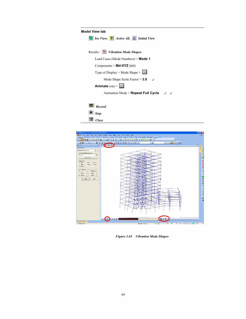
Model View tab
Iso View, Active All, Initial View
Results / Vibration Mode Shapes
Load Cases (Mode Numbers) > Mode 1
Components > Md-XYZ (on)
Type of Display > Mode Shape >
Mode Shape Scale Factor > 3.0 ↵
Animate (on) >
Animation Mode > Repeat Full Cycle ↵ ↵
Record
Stop
Close
Figure 1.65 Vibration Mode Shapes
Application 1. Steel Structure
70
Steel Member Design
Applied Design Code: AISC-LRFD2K
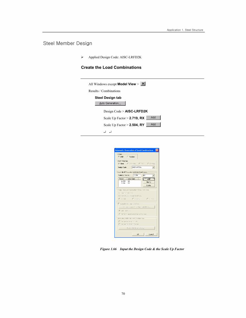
Create the Load Combinations
All Windows except Model View >
Results / Combinations
Steel Design tab
Design Code > AISC-LRFD2K
Scale Up Factor > 2.719, RX
Scale Up Factor > 2.504, RY
↵ ↵
Figure 1.66 Input the Design Code & the Scale Up Factor
71
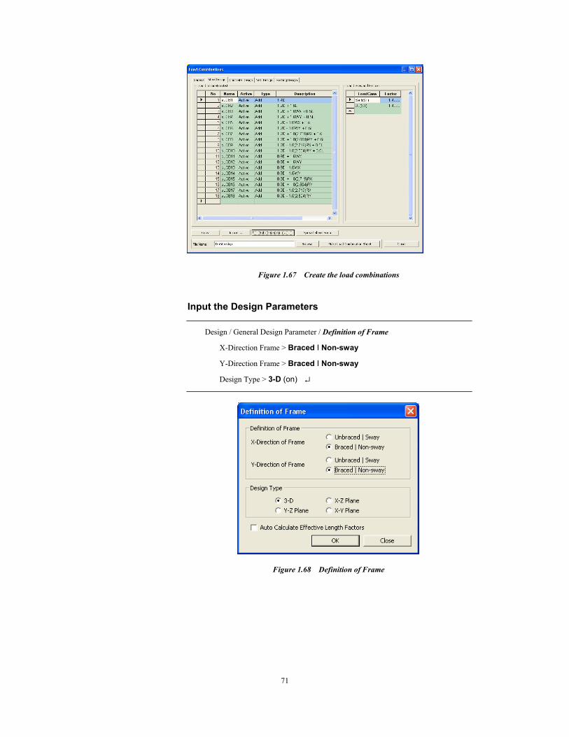
Figure 1.67 Create the load combinations
Input the Design Parameters
Design / General Design Parameter / Definition of Frame
X-Direction Frame > Braced I Non-sway
Y-Direction Frame > Braced I Non-sway
Design Type > 3-D (on) ↵
Figure 1.68 Definition of Frame
Application 1. Steel Structure
72
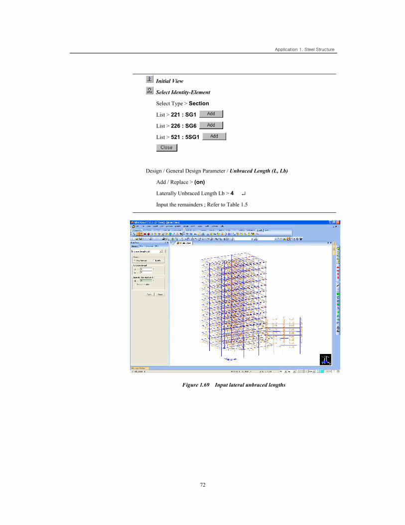
Initial View
Select Identity-Element
Select Type > Section
List > 221 : SG1
List > 226 : SG6
List > 521 : 5SG1
Design / General Design Parameter / Unbraced Length (L, Lb)
Add / Replace > (on)
Laterally Unbraced Length Lb > 4 ↵
Input the remainders ; Refer to Table 1.5
Figure 1.69 Input lateral unbraced lengths
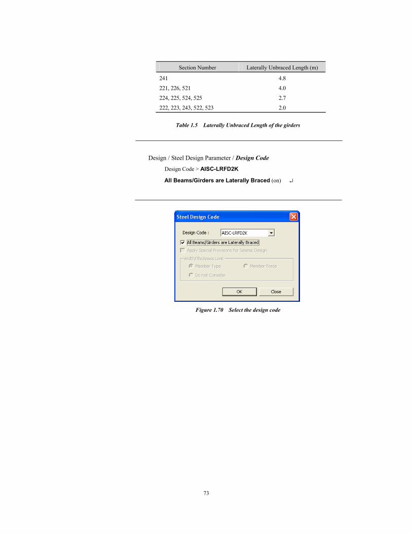
73
Section Number Laterally Unbraced Length (m)
241 4.8
221, 226, 521 4.0
224, 225, 524, 525 2.7
222, 223, 243, 522, 523 2.0
Table 1.5 Laterally Unbraced Length of the girders
Design / Steel Design Parameter / Design Code
Design Code > AISC-LRFD2K
All Beams/Girders are Laterally Braced (on) ↵
Figure 1.70 Select the design code
Application 1. Steel Structure
74
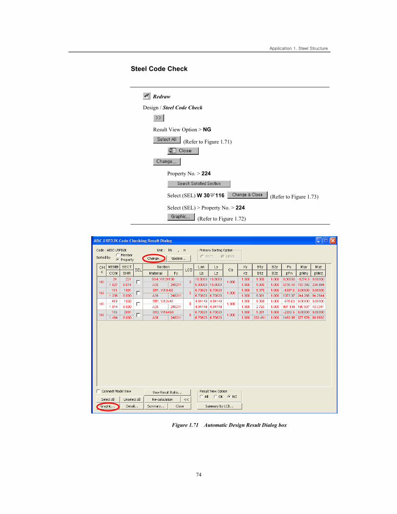
Steel Code Check
Redraw
Design / Steel Code Check
Result View Option > NG
(Refer to Figure 1.71)
Property No. > 224
Select (SEL) W 30×116 (Refer to Figure 1.73)
Select (SEL) > Property No. > 224
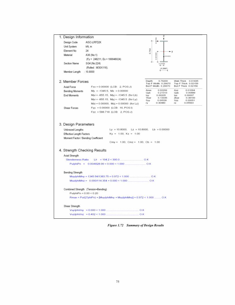
(Refer to Figure 1.72)
Figure 1.71 Automatic Design Result Dialog box
75
Figure 1.72 Summary of Design Results
Application 1. Steel Structure
76
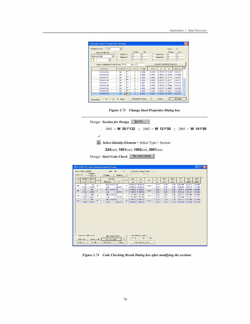
Figure 1.73 Change Steel Properties Dialog box
Design / Section for Design
1001 > W 30×132 ; 1002 > W 12×50 ; 2001 > W 14×90
↵
Select Identity-Element > Select Type > Section
224(on), 1001(on), 1002(on), 2001(on)
Design / Steel Code Check
Figure 1.74 Code Checking Result Dialog box after modifying the sections
77
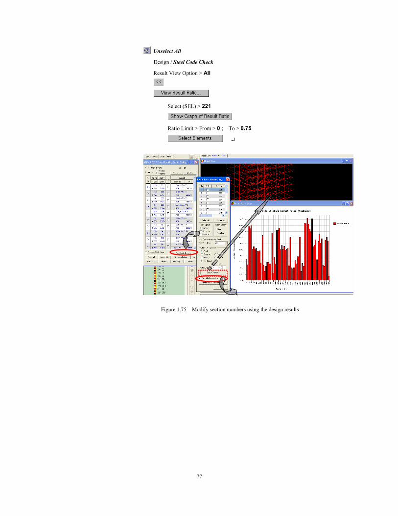
Unselect All
Design / Steel Code Check
Result View Option > All
Select (SEL) > 221
Ratio Limit > From > 0 ; To > 0.75
↵
Figure 1.75 Modify section numbers using the design results
Application 1. Steel Structure
78
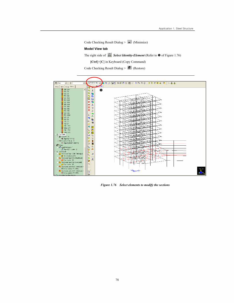
Code Checking Result Dialog > (Minimize)
Model View tab
The right side of Select Identity-Element (Refer to of Figure 1.76)
[Ctrl]+[C] in Keyboard (Copy Command)
Code Checking Result Dialog > (Restore)
Figure 1.76 Select elements to modify the sections
79
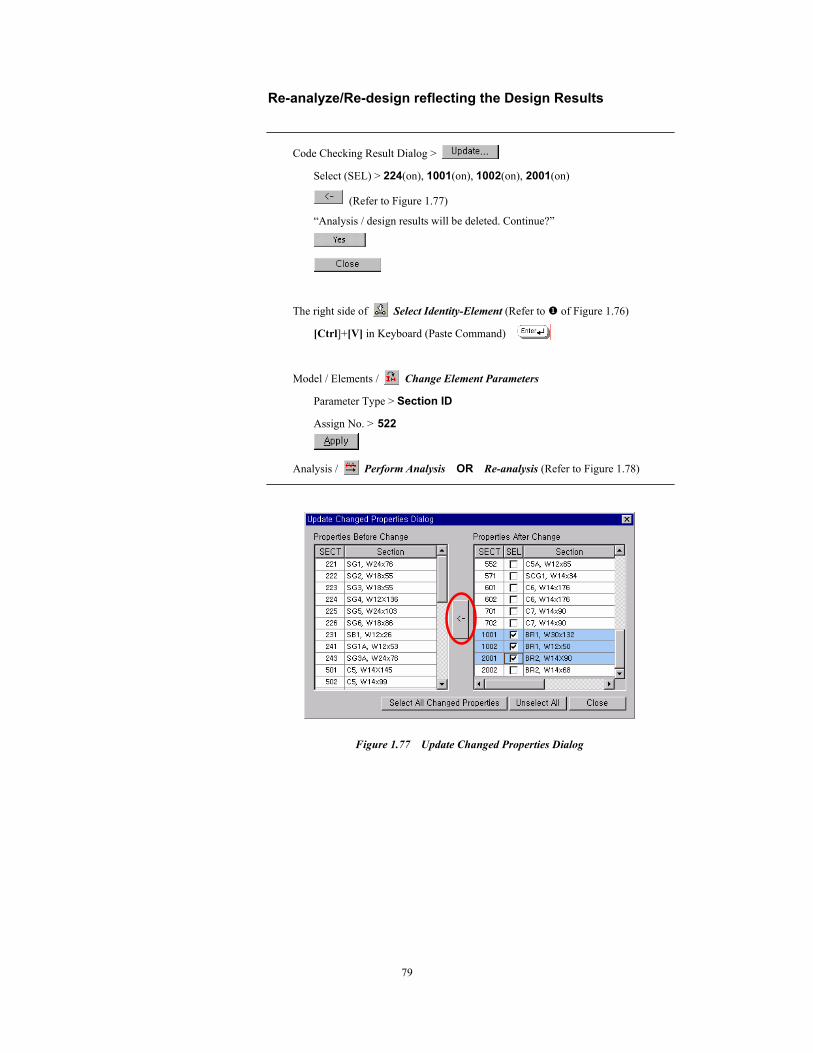
Re-analyze/Re-design reflecting the Design Results
Code Checking Result Dialog >
Select (SEL) > 224(on), 1001(on), 1002(on), 2001(on)
(Refer to Figure 1.77)
“Analysis / design results will be deleted. Continue?”
The right side of Select Identity-Element (Refer to of Figure 1.76)
[Ctrl]+[V] in Keyboard (Paste Command)
Model / Elements / Change Element Parameters
Parameter Type > Section ID
Assign No. > 522
Analysis / Perform Analysis OR Re-analysis (Refer to Figure 1.78)
Figure 1.77 Update Changed Properties Dialog
Application 1. Steel Structure
80
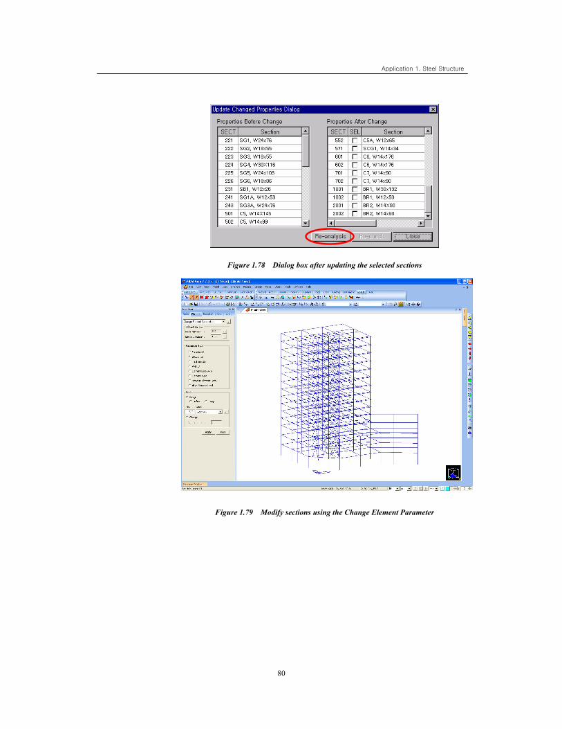
Figure 1.78 Dialog box after updating the selected sections
Figure 1.79 Modify sections using the Change Element Parameter
81
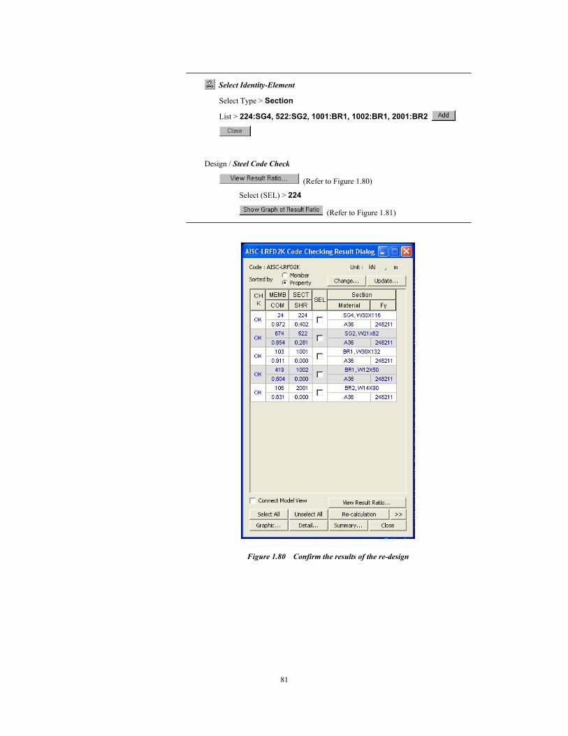
Select Identity-Element
Select Type > Section
List > 224:SG4, 522:SG2, 1001:BR1, 1002:BR1, 2001:BR2
Design / Steel Code Check
(Refer to Figure 1.80)
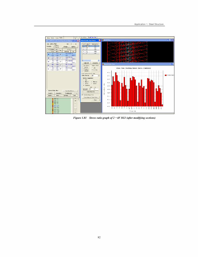
Select (SEL) > 224
(Refer to Figure 1.81)
Figure 1.80 Confirm the results of the re-design
Application 1. Steel Structure
82
Figure 1.81 Stress ratio graph of 2∼4F SG1 (after modifying sections)
83
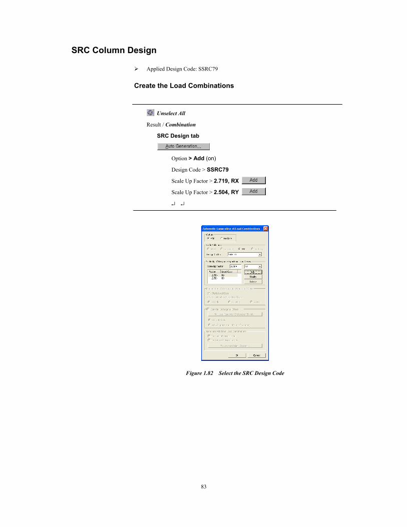
SRC Column Design
Applied Design Code: SSRC79 Create the Load Combinations
Unselect All
Result / Combination
SRC Design tab
Option > Add (on)
Design Code > SSRC79
Scale Up Factor > 2.719, RX
Scale Up Factor > 2.504, RY
↵ ↵
Figure 1.82 Select the SRC Design Code
Application 1. Steel Structure
84
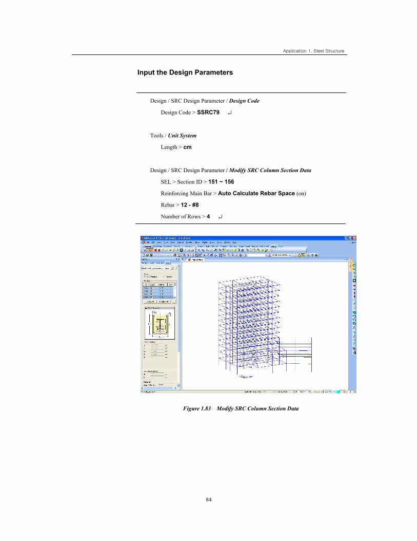
Input the Design Parameters
Design / SRC Design Parameter / Design Code
Design Code > SSRC79 ↵
Tools / Unit System
Length > cm
Design / SRC Design Parameter / Modify SRC Column Section Data
SEL > Section ID > 151 ~ 156
Reinforcing Main Bar > Auto Calculate Rebar Space (on)
Rebar > 12 - #8
Number of Rows > 4 ↵
Figure 1.83 Modify SRC Column Section Data
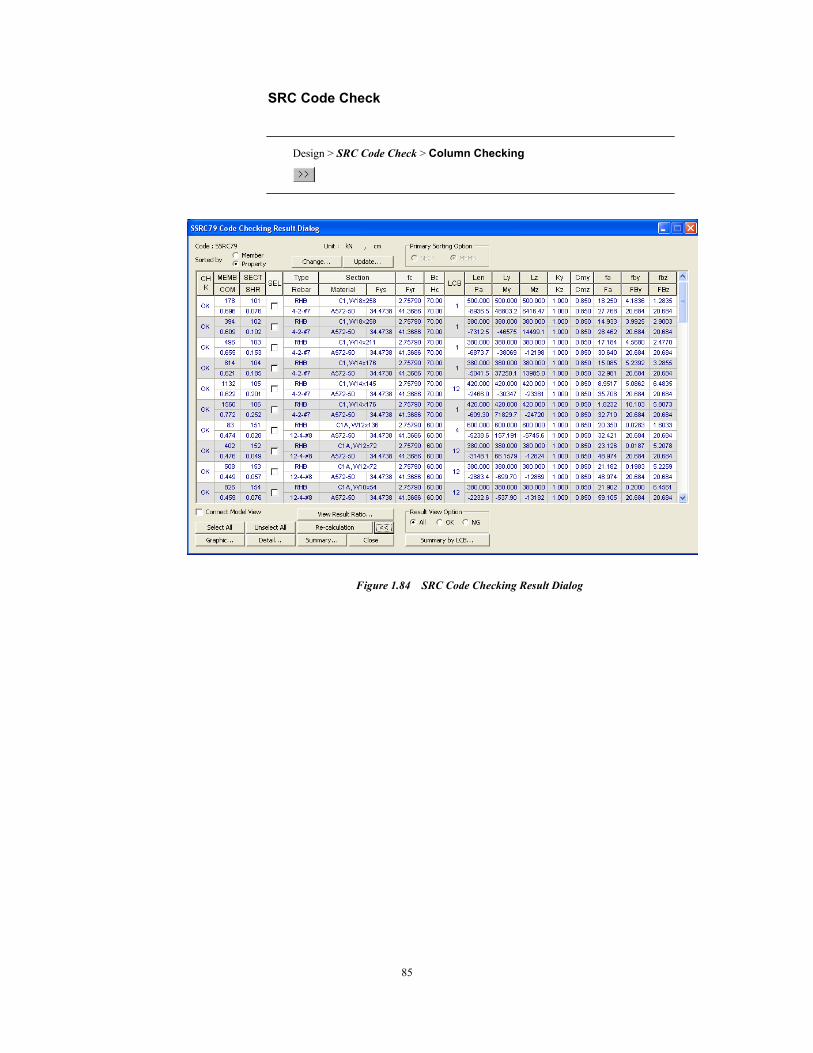
85
SRC Code Check
Design > SRC Code Check > Column Checking
Figure 1.84 SRC Code Checking Result Dialog