Parker Catálogo de Válvulas Proporcionales
62
Catalog HY15-3502/US Proportional Valves Contents Parker Hannifin Corporation Hydraulic Cartridge Systems C h e c k V a l v e s S h u t t l e V a l v e s L o a d / M o t o r C o n t r o l s F l o w C o n t r o l s P r e s s u r e C o n t r o l s L o g i c E l e m e n t s D i r e c t i o n a l C o n t r o l s M a n u a l V a l v e s P r o p o r t i o n a l V a l v e s C o i l s & E l e c t r o n i c s T e c h n i c a l D a t a SH CV LM FC PC LE DC MV SV PV CE BC TD B o d i e s & C a v i t i e s S o l e n o i d V a l v e s SERIES CAVITY DESCRIPTION FLOW PRESSURE PAGE NO. LPM/GPM BAR/PSI PRESSURE RELIEVING AP01B2YP . ....... 2G ... ............ Increase Pressure/Increase Current .............. 5.3/1.4 ...... 350/5000 .............. PV7-PV8 AP02B2YP ........ C08-2 .......... Increase Press ure/Increase Current ..............5.3/1.4 ...... 350/5000 ....... ..... PV9-PV10 AP04G2YP ........ C10-2 .......... Increase Pressure/Increase Current ................45/12 ...... 350/5000 .......... PV11-PV12 AP01B2YR ........ 2G ............... Decrease Pressure/Increase Current .............5.3/1.4 ...... 350/5000 .......... PV13-PV14 AP02B2YR ........ C08-2 .......... Decrease Pressure/Increase Current .............5.3/1.4 ...... 350/5000 .......... PV15-PV16 AP04G2YR ....... C10-2 .......... Decrease Pressure/Increase Current ...............95/25 ...... 350/5000 .......... PV17-PV18 PRESSURE REDUCING GP01 30 ........... 54-1 ..... ....... Pressure Reducing Valve ................................ 1.9/.5 ...... 210/3000 .......... PV19-PV20 GTP02 34 .. ....... C08-3 .......... Pressure Re ducing Valve ...... ............................19/5 ...... 210/3000 .......... PV21-PV22 GTP04 34 ......... 3X ........... .... Press ure Reducing Valve .......... ................ ........30 /8 ...... 210/3000 .......... PV23-PV24 FLOW CONTROLS, 2-Way DF122C ............. C12-2 .......... Flow Control, N.C. ...... ..................................... 53/14 ...... 210/3000 .......... PV25-PV26 DF161C ............. C16-2 .......... Flow Control, N.C. .........................................150/40 ...... 210/3000 . ......... PV27-PV28 DF201C ............. C20-2 .......... Flow Control, N.C. ....... ..................................325/60 ...... 210/3000 . ......... PV29-PV30 HP02C ........... ... 2X .............. . Flow Control, N.C. ................... ................ ..........23/6 ...... 210/3000 .......... PV31-PV32 JP02C ...............C0 8-3 .......... Flow Control, N.C. ............................................. 23/6 ...... 210/3000 .......... PV33-PV34 HP04C .... .......... C10-2 .......... Flow Control, N.C. ........... ...............................36/9.5 ...... 210/3000 .......... PV35-PV36 JP04C 21 .......... 3X ........ ....... Flow Control, N.C. ............. ................ .............36/9.5 ...... 210/3000 ........ .. PV37-PV38 DFA125C21* .... C12-3L ........ Flow Control, N .C. ........................................56.8/15 ...... 210/3000 .......... PV39-PV40 *The DFA125C21 will be available January 1, 2011. HP02P .............. 2X .............. . Flow Control, N.O. ........ ..................................... 19/5 ...... 210/3000 .......... PV41-PV42 JP02P ...............C0 8-3 .......... Flow Control, N.O. ................................ .............19/5 ...... 210/3000 .......... PV43-PV44 HP04P .............. C10-2 .......... Flow Control, N.O. .............................................30/8 ...... 210/3000 .......... PV45-PV46 JP04P ............... 3X ......... ...... Flow Control, N.O. ... ................................ .......36 /9.5 ...... 210/3000 ......... . PV47-PV48 DF122N ............ C12-2 .......... Flow Control, N.O. ...........................................5 3/14 ...... 210/3000 .......... PV49-PV50 FLOW CONTROLS, 3-WAY JP04C 31 .......... 4C ..... .......... Priority F low Control, N.C.................................. 30/8 ...... 210/3000 ...... .... PV51-PV52 DFA125C31 .. .... C12-4L ........ Priority Flow Control, N.C. ................ ............56.8/15 ...... 210/3000 .......... PV53-PV54 DIRECTIONAL CONTROL GP02 51 ........... C08-4 .......... 4 Way , 3 Pos - Closed Center ................ .........21/5.5 ...... 350/5000 .......... PV55-PV56 GP02 53 ........... C08-4 .......... 4 Way, 3 Pos - Float Center ............................17/4.5 ...... 350/5000 .......... PV57-PV58 DSP105C1 ........ C10-4 .......... 4 Way, 3 Pos - Closed Center .........................32 /8.5 ...... 210/3000 .......... PV59-PV61 DSP105C4 ........ C10-4 .......... 4 Way, 3 Pos - Float Center ... ................. ........32 /8.5 ...... 210/3000 ......... . PV59-PV61
-
Upload
juan-ignacio-dvalle-iii -
Category
Documents
-
view
223 -
download
1
Transcript of Parker Catálogo de Válvulas Proporcionales

8/16/2019 Parker Catálogo de Válvulas Proporcionales
http://slidepdf.com/reader/full/parker-catalogo-de-valvulas-proporcionales 1/62
Catalog HY15-3502/US
Proportional ValvesContents
Parker Hannifin Corporation
Hydraulic Cartridge Systems
SERIES CAVITY DESCRIPTION FLOW PRESSURE PAGE NO.LPM/GPM BAR/PSI
PRESSURE RELIEVING
AP01B2YP ........ 2G ............... Increase Pressure/Increase Current ..............5.3/1.4 ...... 350/5000 ..............PV7-PV8
AP02B2YP ........ C08-2 .......... Increase Pressure/Increase Current ..............5.3/1.4 ...... 350/5000 ............ PV9-PV10
AP04G2YP ........ C10-2 .......... Increase Pressure/Increase Current ................45/12 ...... 350/5000 .......... PV11-PV12
AP01B2YR ........ 2G ............... Decrease Pressure/Increase Current .............5.3/1.4 ...... 350/5000 .......... PV13-PV14
AP02B2YR ........ C08-2 .......... Decrease Pressure/Increase Current .............5.3/1.4 ...... 350/5000 .......... PV15-PV16
AP04G2YR ....... C10-2 .......... Decrease Pressure/Increase Current ...............95/25 ...... 350/5000 .......... PV17-PV18
PRESSURE REDUCING
GP01 30 ...........54-1 ............ Pressure Reducing Valve ................................1.9/.5 ...... 210/3000 ..........PV19-PV20
GTP02 34 ......... C08-3 .......... Pressure Reducing Valve ..................................19/5 ...... 210/3000 .......... PV21-PV22
GTP04 34 .........3X ............... Pressure Reducing Valve ..................................30/8 ...... 210/3000 ..........PV23-PV24
FLOW CONTROLS, 2-Way
DF122C.............C12-2 .......... Flow Control, N.C. ...........................................53/14 ......210/3000 .......... PV25-PV26
DF161C.............C16-2 .......... Flow Control, N.C. .........................................150/40 ...... 210/3000 .......... PV27-PV28
DF201C.............C20-2 .......... Flow Control, N.C. .........................................325/60 ...... 210/3000 .......... PV29-PV30
HP02C .............. 2X ............... Flow Control, N.C. .............................................23/6 ...... 210/3000 ..........PV31-PV32
JP02C ...............C08-3 .......... Flow Control, N.C. .............................................23/6 ......210/3000 .......... PV33-PV34
HP04C ..............C10-2 .......... Flow Control, N.C. ..........................................36/9.5 ...... 210/3000 .......... PV35-PV36
JP04C 21 ..........3X ............... Flow Control, N.C. ..........................................36/9.5 ...... 210/3000 .......... PV37-PV38DFA125C21* ....C12-3L ........ Flow Control, N.C. ........................................56.8/15 ...... 210/3000 .......... PV39-PV40
*The DFA125C21 will be available January 1, 2011.
HP02P .............. 2X ............... Flow Control, N.O. .............................................19/5 ...... 210/3000 ..........PV41-PV42
JP02P ...............C08-3 .......... Flow Control, N.O. .............................................19/5 ...... 210/3000 .......... PV43-PV44
HP04P .............. C10-2 .......... Flow Control, N.O. .............................................30/8 ...... 210/3000 .......... PV45-PV46
JP04P ............... 3X ............... Flow Control, N.O. ..........................................36/9.5 ...... 210/3000 .......... PV47-PV48
DF122N ............ C12-2 .......... Flow Control, N.O. ...........................................53/14 ...... 210/3000 .......... PV49-PV50
FLOW CONTROLS, 3-WAY
JP04C 31 ..........4C ............... Priority Flow Control, N.C. ................................. 30/8 ...... 210/3000 .......... PV51-PV52
DFA125C31 ...... C12-4L ........ Priority Flow Control, N.C. ............................56.8/15 ...... 210/3000 .......... PV53-PV54
DIRECTIONAL CONTROL
GP02 51 ........... C08-4 .......... 4 Way, 3 Pos - Closed Center .........................21/5.5 ...... 350/5000 ..........PV55-PV56
GP02 53 ........... C08-4 .......... 4 Way, 3 Pos - Float Center ............................17/4.5 ...... 350/5000 ..........PV57-PV58
DSP105C1 ........ C10-4 .......... 4 Way, 3 Pos - Closed Center .........................32/8.5 ...... 210/3000 .......... PV59-PV61
DSP105C4 ........ C10-4 .......... 4 Way, 3 Pos - Float Center ............................32/8.5 ...... 210/3000 .......... PV59-PV61

8/16/2019 Parker Catálogo de Válvulas Proporcionales
http://slidepdf.com/reader/full/parker-catalogo-de-valvulas-proporcionales 2/62
PV1
Proportional Control ValvesCatalog HY15-3502/US
Technical Tips
Parker Hannifin Corporation
Hydraulic Cartridge Systems
C h e c k
V a l v e s
S h u t t l e
V a l v
e s
L o a d / M o t o r
C o n t r o l s
F l o w
C o n t r o l s
P r e s
s u r e
C o n
t r o l s
L o g i c
E l e me n t s
D i r e c t i o n a l
C o n t r o l s
M a n u a l
V a l v e s
S o l e n o i d
V a l v e s
P r o p o r t i o n a l
V a l v e s
C o i l s &
E l e c t r o n i c s
B o d i e s &
C a v i t i e s
T e c h n i c a l
D a t a
SH
CV
LM
FC
PC
LE
DC
MV
SV
PV
CE
BC
TD
INTRODUCTIONThis technical tips section is designed to help familiarize you with the Parker line of Proportional Valves. In thissection we present common options, technical terms, as well as a brief synopsis of the operation and applications
of the various products offered in this section. The intent of this section is to help you in selecting the bestproducts for your application.
Seals: The majority of the products are available inNitrile or Fluorocarbon Seals. The Winner’s Circle
products feature a standard 4301 Polyurethane“D”-Ring. The “D”-Ring eliminates the need for backuprings. You should match the seal compatibility to the
temperature and fluid being used in your application.
Overrides: Overrides are standard on many of theParker proportional valves. The override is generally a
push type that is flush with the end of the tube. Consultthe individual catalog pages for more details.
TECHNICAL TERMSTo help in applying our proportional valve line ofproduct, we have listed some technical terms below,
as well as some helpful hints in applying our valves.
Ohm’s Law: Electrical current is generated as a resultof the relationship between input voltage and the
resistance to the flow of electrical current. It isrepresented in equation form by I = V/R (or V=IR),
where I is current, V is voltage and R is resistance.This is an important relationship to remember whendealing with any electrically operated valves.
Proportional valves allow varying control of flow orpressure, dependant on the current signal provided.As coils heat up, their resistance rises. This means a
higher voltage must be available to maintain the same
amount of pressure or flow. Thus, the applicationneeds to be designed such that the full on position isabout 70% of the initial current draw. On the individualcatalog pages a maximum control current is specified
to help in applying our proportional valves.
PWM: Pulse Width Modulation (PWM) is the preferredsignal for controlling electrical current. PWM is on / off
voltage in a square wave form. The percent “on” timeor duty cycle provides the average voltage. The valve
driver adjusts the duty cycle to obtain current control.We recommend valve drivers with current control foroptimum performance. PWM signals also usually
provide dither for the proportional valve. Dither is a
small back and forth movement of the valve spoolaround its set position. This rapid movement reduces
the friction of the valve and leads to faster, moreaccurate response.
PWM Frequency: The frequency of a PWM signal isthe rate at which the signal is turned on and off.
Parker’s analog proportional valves are designed towork with low frequency responses between 100-400Hz. The performance curves on our catalog pages
were performed with a PWM signal at 200 Hz.
Hysteresis: Due to various factors, the performanceof a proportional valve will show a slightly differentperformance when the current signal is increasing than
it will when the signal is being decreased. This
difference is usually expressed as a percentage of
total input change and is referred to as the hysteresisof the valve.
Deadband: Cracking or deadband refers to the
amount of the control signal that is needed to produceany movement of the spool. Thus, a 20% deadbandmeans that 20% of the control signal is needed before
the spool will move.
COMMON OPTIONSAs you will see, Parker offers a variety of Proportional Valve products. As such, some of the options mentioned
below may not be available on all valves. Consult the model coding and dimensions for each valve for specifics.
Here are some of the common options available.

8/16/2019 Parker Catálogo de Válvulas Proporcionales
http://slidepdf.com/reader/full/parker-catalogo-de-valvulas-proporcionales 3/62
PV2
Catalog HY15-3502/US
Proportional Control ValvesTechnical Tips
Parker Hannifin Corporation
Hydraulic Cartridge Systems
PRODUCT TYPES / APPLICATIONSProportional valves are nothing more than electrically adjustable hydraulic valves. They give the operator nearlyinfinite adjustment control and flexibility. Parker Hannifin offers various types of proportional flow control, pressure
reducing, and relief valves.
Proportional Flow Control Valve
Proportional flow control valves provide pseudo pressure compensation and are used on systems requiringvariable electronic control of flow. They allow the operator to vary the control signal to accelerate or decelerate an
actuator. A compensator valve can be added to the circuit for enhanced compensation. Some typical applicationswould include the hoist control for a lift, or the speed control for a winch circuit. Parker offers both normally closedand normally open versions of proportional flow controls.
Normally Closed
Proportional Flow Control
OPERATION - With the solenoid
coil de-energized, the spool is held ina closed position by the spring force. When the
solenoid coil is energized, the amperage of the
signal moves the spool into an open position.The spool is held in this position by a balance between spring force and electrical force. As the current increases,
the spools opens further; allowing more flow. As the current decreases, the spool begins closing; allowing less
flow. Pseudo compensation is obtained by the pressure drop across the orifices in the spool.
Normally Open
Proportional Flow Control
OPERATION - With the solenoidcoil de-energized, the spool is held inan open position by spring force; allowing full flow
to pass. As the solenoid coil is energized, the spoolbegins to move away from a full open position;
allowing less flow to pass. Once a full electronic signal is given, the spool is held in a closed position; allowing noflow to pass. As the electronic signal is then reduced, the spool begins to open; allowing flow to pass again. Once
a constant electronic signal is given, the spool is held in that position by a balance between electronic force andspring force. Pseudo compensation is obtained by the pressure drop across the orifices in the spool.
Normally Closed Proportional Needle Valve
The proportional needle valvesare electronic controlled variable
needle valves. They are designedspecifically for bleed off or unloading
circuits as back pressure will affect performance.
OPERATION - With the solenoid de-energized, the main
poppet is held in the closed position by spring force. Whenthe solenoid is energized, the sensing spool moves into a partially open position relative to the percentage of
rated current flowing through the coil. This action allows the main poppet to move away from the valve seat to adegree that corresponds to sensing spool position. The valve will maintain a fixed amount of opening as long asthe electrical current remains constant and will vary proportionally with an increase or decrease in current.
In(1)
Out (2)
Inlet (2)
Outlet(1)
(3)(2)
Port (1)Is Not Used

8/16/2019 Parker Catálogo de Válvulas Proporcionales
http://slidepdf.com/reader/full/parker-catalogo-de-valvulas-proporcionales 4/62

8/16/2019 Parker Catálogo de Válvulas Proporcionales
http://slidepdf.com/reader/full/parker-catalogo-de-valvulas-proporcionales 5/62
PV4
Catalog HY15-3502/US
Proportional Control ValvesTechnical Tips
Parker Hannifin Corporation
Hydraulic Cartridge Systems
Normally Closed Proportional Pressure Reducing / Relieving Valve Normally Closed Proportional Pressure Reducing/Relieving Valves are used to electronically reduce the inlet pres-
sure to one leg of a hydraulic circuit. In addition these valves act as a relief valve, relieving any shocks or surgesthat occur between its regulating port and the actuator. Parker offers direct acting and pilot operated versions of
this valve. The direct acting valves are faster responding and generally have lower hysteresis, but are limited tosmaller reduced pressures (generally below 800 psi depending on the valve.) Pilot operated are generally sloweron response due to the two stage performance, but can have a reduced pressure as high as 3000 psi.
Direct Acting
OPERATION - With the solenoid
coil de-energized, the spool is heldin a closed position by spring force.In this mode, the regulated pressure port is open to tank
and the pressure inlet port is blocked. As an electronicsignal is applied to the solenoid coil, the spool will begin
to travel to a position where the pressure inlet port is connected to the regulated pressure port. At this point,reduced pressure becomes a function of the voltage signal. As long as the electronic signal is constant, thereduced pressure at the regulated pressure port will remain fixed regardless of any changes in inlet flow or inlet
pressure. As the electronic signal increases or decreases, the reduced pressure at the regulated port will change
with respect to the change in electronic signal. Once a full signal is given, the reduced pressure of the regulatedpressure port will be at the maximum reduced pressure for that valve.
Pilot Operated
OPERATION - With the solenoidcoil de-energized, the pilot dart isheld open by the spring force. This
allows the main spool to close and restricts flow fromgoing from the inlet (2) port to the regulated port (1).
As the electronic signal is applied to the coil, the pilot dartis moved towards the pilot seat restricting pilot flow. This
restriction raises the effective pressure inside the chamber between the spool and the pilot seat, allowing thespool to travel away from the pilot seat to a position where the pressure at inlet (2) is connected to the regulatedpressure port (1). At this point, reduced pressure becomes a function of the electronic signal. As long as the
electronic signal is constant, the reduced pressure at the regulated pressure port (2) will remain fixed regardlessof any changes in inlet flow or inlet pressure. As the electronic signal increases or decreases, the reduced
pressure at port (1) will change with respect to the change in the electronic signal.
Reg.(1)
(3) TankPressure (2)
Reg.(1)
(3) TankIn (2)

8/16/2019 Parker Catálogo de Válvulas Proporcionales
http://slidepdf.com/reader/full/parker-catalogo-de-valvulas-proporcionales 6/62
PV5
Proportional Control ValvesCatalog HY15-3502/US
Technical Tips
Parker Hannifin Corporation
Hydraulic Cartridge Systems
C h e c k
V a l v e s
S h u t t l e
V a l v
e s
L o a d / M o t o r
C o n t r o l s
F l o w
C o n t r o l s
P r e s
s u r e
C o n
t r o l s
L o g i c
E l e me n t s
D i r e c t i o n a l
C o n t r o l s
M a n u a l
V a l v e s
S o l e n o i d
V a l v e s
P r o p o r t i o n a l
V a l v e s
C o i l s &
E l e c t r o n i c s
B o d i e s &
C a v i t i e s
T e c h n i c a l
D a t a
SH
CV
LM
FC
PC
LE
DC
MV
SV
PV
CE
BC
TD
Normally Closed Proportional Relief Valve
Normally closed proportional reliefvalves are used to electronically
control the system pressure.These valves are ideal for circuitswith varying system pressures
demands. A small flow pilot versionof the normally closed proportional relief is also offered for
piloting a larger logic element or vented relief valve. The normallyclosed relief defaults to a maximum pressure setting (i.e. 3000 psi) when there is no current applied.
OPERATION - With the solenoid coil de-energized, the pilot dart is held closed by the spring. As current is appliedto the coil, the pilot dart is moved creating less restriction of the pilot flow. As this restriction is reduced with the
increasing current, the pressure setting also decreases. Once a constant electronic signal is given, the pilot dart isheld in a given position, holding the pressure setting. This is maintained by the balance between the electronic
spring force and the inlet pressure.
Normally Open
Proportional Relief Valve Normally open proportional relief
valves are used to electronically
control the system pressure.These valves are ideal for circuitswith varying system pressure
demands. A small flow pilot versionof the normally open proportional relief is also offered
for piloting a larger logic element or vented relief valve. The normally open relief defaults to minimum systempressure (i.e. 150 psi) when there is no current applied. Normally closed versions are also available upon request.
OPERATION - With the solenoid coil de-energized, the pilot dart is held open by the spring. This allows the mainspool to open at minimum pressure 10.4 Bar (150 psi). As current is applied to the coil, the pilot dart is moved
towards the pilot seat restricting pilot flow. This restriction raises the effective pressure setting of the valve. Oncea constant electronic signal is given, the pilot dart is held in a given position, holding the pressure setting. This is
maintained by a balance between electronic spring force and inlet pressure. As the electronic signal is reduced,the pilot dart is moved away from the pilot seat. This lowers the effective pressure setting of the valve.
(1)
(2)
(1)

8/16/2019 Parker Catálogo de Válvulas Proporcionales
http://slidepdf.com/reader/full/parker-catalogo-de-valvulas-proporcionales 7/62

8/16/2019 Parker Catálogo de Válvulas Proporcionales
http://slidepdf.com/reader/full/parker-catalogo-de-valvulas-proporcionales 8/62
Catalog HY15-3502/US
Parker Hannifin Corporation
Hydraulic Cartridge Systems
C h e c k
V a l v e s
S h u t t l e
V a l v
e s
L o a d / M o t o r
C o n t r o l s
F l o w
C o n t r o l s
P r e s
s u r e
C o n
t r o l s
L o g i c
E l e me n t s
D i r e c t i o n a l
C o n t r o l s
M a n u a l
V a l v e s
S o l e n o i d
V a l v e s
P r o p o r t i o n a l
V a l v e s
C o i l s &
E l e c t r o n i c s
B o d i e s &
C a v i t i e s
T e c h n i c a l
D a t a
SH
CV
LM
FC
PC
LE
DC
MV
SV
PV
CE
BC
TD
PV7
Proportional Relief ValveSeries AP01B2YP 07C, 14C, 21C, 35CTechnical Information
Specifications
Rated Flow 07C 5.3 LPM (1.4 GPM)(At 70 PSI ∆∆∆∆∆P) 14C 3.4 LPM (0.9 GPM)
21C 3.0 LPM (0.8 GPM)35C 1.3 LPM (.35 GPM)
Max. Pressure At 07C 70 Bar (1000 PSI)Port 1 @ 75% 14C 140 Bar (2000 PSI)Input Current 21C 210 Bar (3000 PSI)
35C 350 Bar (5000 PSI)
Hysteresis @ 5%
200 Hz PWM
Cracking 07C .07 Bar (1 PSI)Pressure 14C .14 Bar (2 PSI)
21C .21 Bar (3 PSI)35C .35 Bar (4 PSI)
Cartridge Material All parts steel. All operatingparts hardened steel.
Operating Temp. -40°C to +93.3°C (Nitrile)Range/Seals (-40°F to +200°F)
-31.7°C to +121.1°C (Fluorocarbon)(-25°F to +250°F)
Fluid Mineral-based or synthetic withCompatibility/ lubricating properties at viscositiesViscosity of 45 to 2000 SSU (6 to 420 cSt)
Filtration ISO Code 16/13,SAE Class 4 or better
Approx. Weight .06 kg (.14 lbs.)
Cavity 2G(See BC Section for more details)
General Description
Proportional Relief Valve. Increasing Pressure With
Increasing Current. For additional information seeTechnical Tips on pages PV1-PV6.
Features• Analog Proportional Relief Valve regulates pressure
proportionally to the solenoid current
• Direct acting poppet design
• One piece cartridge housing ensures internalconcentricity
• Coil: Waterproof, hermetically sealed, requires noO’Rings; Symmetrical coil can be reversed withoutaffecting performance.
Performance Curves
PWM Current Regulator Recommended
(1) (2)(1)
(2)
Hydraulic Oil 150 SSU @ 100°F (32 cSt)
0
1000
5000 345
205
274
137
68
Pressure3000
4000
PSI Bar
2000
Current (%)
6020 400
80 100
Pressure vs. Input Signal (Current)
-07
-14
-21
-35Measured at coil stabilizedtemperature and nominal flow
Flow (Q)
3.8
1.0
4.5
1.2
0.8
0.2
1.5
0.4
2.3
0.6
3.0
0.8
LPM
GPM0
5.3
1.4
0
80
40
8.6
5.7
2.0
120
200 14.3
11.4160
PSI Bar
PressureDrop
(
P)
-35
-14
-21
-07
Measured atDe-energized coil
Hydraulic Oil 150 SSU @ 100°F (32 cSt)
Pressure Drop vs. Flow

8/16/2019 Parker Catálogo de Válvulas Proporcionales
http://slidepdf.com/reader/full/parker-catalogo-de-valvulas-proporcionales 9/62
Catalog HY15-3502/US
Parker Hannifin Corporation
Hydraulic Cartridge Systems
Proportional Relief ValveSeries AP01B2YP 07C, 14C, 21C, 35C
PV8
Technical Information
Seals CoilType
CoilTermination
Code Coil Voltage
Omit Without Coil
D012 12 VDC
D024 24 VDC
Code Seals / Kit No.
N Nitrile / Buna-N (Std.)(SK30129N-1)
V Fluorocarbon / (SK30129V-1)
E Ethylene Propylene
CoilVoltage
AP01B2YP
08 SizeProportionalRelief Valve
Style
Dimensions Millimeters (Inches)
Ordering Information
THIRD-ANGLEPROJECTION
Code Style (MaximumRelief Pressure)
07C 70 Bar (1000 PSI)
14C 140 Bar (2000 PSI)
21C 210 Bar (3000 PSI)
35C 350 Bar (5000 PSI)
Code Porting
324 1/4″ SAE
325 1/4″ BSP
Body MaterialPorting
Code Body Material
A Aluminum
S Steel
Line Body
LB10
Order Bodies Separately
Code Coil Type
Omit Without Coil
SP Super Coil - 19 Watts
62.7(2.47)
19.8(0.78)
33.8(1.33)
X X V D C
X X W
C C X
X X X
H
MA DE I N U. S .A .
P A T .X X X X X X X
75.7(2.98)
17.9(0.70)
5/8 Hex.4.1 Nm
(3 lb. ft.)Torque
5/8-18 UNF
3/4 Hex.24 Nm (18 lb. ft.)Torque
12.7(0.50)
(1)
(2)
39.6(1.56)
See Super Coil1/2" I.D.Information ForTerminal Connectors
Code Coil Termination
Omit Without Coil
D DIN Plug Face
A Amp Jr. Timer*
L Dual Lead Wire*
LS Sealed Lead Wire*
H Molded Deutsch*
See Super Coil 1/2 ″ ″ ″ ″ ″ I.D.*DC Only
NOTE: Requires 2G Cavity
Custom pressure setting available.Consult factory.

8/16/2019 Parker Catálogo de Válvulas Proporcionales
http://slidepdf.com/reader/full/parker-catalogo-de-valvulas-proporcionales 10/62
Catalog HY15-3502/US
Parker Hannifin Corporation
Hydraulic Cartridge Systems
C h e c k
V a l v e s
S h u t t l e
V a l v
e s
L o a d / M o t o r
C o n t r o l s
F l o w
C o n t r o l s
P r e s
s u r e
C o n
t r o l s
L o g i c
E l e me n t s
D i r e c t i o n a l
C o n t r o l s
M a n u a l
V a l v e s
S o l e n o i d
V a l v e s
P r o p o r t i o n a l
V a l v e s
C o i l s &
E l e c t r o n i c s
B o d i e s &
C a v i t i e s
T e c h n i c a l
D a t a
SH
CV
LM
FC
PC
LE
DC
MV
SV
PV
CE
BC
TD
PV9
Proportional Relief ValveSeries AP02B2YP 07C, 14C, 21C, 35CTechnical Information
Specifications
Rated Flow 07C 5.3 LPM (1.4 GPM)(At 70 PSI ∆∆∆∆∆P) 14C 3.4 LPM (0.9 GPM)
21C 3.0 LPM (0.8 GPM)35C 1.3 LPM (.35 GPM)
Max. Pressure At 07C 70 Bar (1000 PSI)Port 1 @ 75% 14C 140 Bar (2000 PSI)Input Current 21C 210 Bar (3000 PSI)
35C 350 Bar (5000 PSI)
Hysteresis @ 5%
200 Hz PWM
Cracking 07C .07 Bar (1 PSI)Pressure 14C .14 Bar (2 PSI)
21C .21 Bar (3 PSI)35C .35 Bar (4 PSI)
Cartridge Material All parts steel. All operatingparts hardened steel.
Operating Temp. -40°C to +93.3°C (Nitrile)Range/Seals (-40°F to +200°F)
-31.7°C to +121.1°C (Fluorocarbon)(-25°F to +250°F)
Fluid Mineral-based or synthetic withCompatibility/ lubricating properties at viscositiesViscosity of 45 to 2000 SSU (6 to 420 cSt)
Filtration ISO Code 16/13,SAE Class 4 or better
Approx. Weight .06 kg (.14 lbs.)
Cavity C08-2(See BC Section for more details)
General Description
Proportional Relief Valve. Increasing Pressure With
Increasing Current. For additional information seeTechnical Tips on pages PV1-PV6.
Features
• Analog Proportional Relief Valve regulates pressureproportionally to the solenoid current
• Direct acting poppet design
• One piece cartridge housing ensures internalconcentricity
• Coil: Waterproof, hermetically sealed, requires noO’Rings; Symmetrical coil can be reversed withoutaffecting performance.
NOTE: This valve will be available January 1, 2011.
Performance Curves
PWM Current Regulator Recommended
(1) (2)
(2)
(1)
Hydraulic Oil 150 SSU @ 100°F (32 cSt)
0
1000
5000 345
205
274
137
68
Pressure3000
4000
PSI Bar
2000
Current (%)
6020 400
80 100
Pressure vs. Input Signal (Current)
-07
-14
-21
-35Measured at coil stabilizedtemperature and nominal flow
Flow (Q)
3.8
1.0
4.5
1.2
0.8
0.2
1.5
0.4
2.3
0.6
3.0
0.8
LPM
GPM0
5.3
1.4
0
80
40
8.6
5.7
2.0
120
200 14.3
11.4160
PSI Bar
PressureDrop
(
P)
-35
-14
-21
-07
Measured atDe-energized coil
Hydraulic Oil 150 SSU @ 100°F (32 cSt)
Pressure Drop vs. Flow
8/16/2019 Parker Catálogo de Válvulas Proporcionales
http://slidepdf.com/reader/full/parker-catalogo-de-valvulas-proporcionales 11/62
Catalog HY15-3502/US
Parker Hannifin Corporation
Hydraulic Cartridge Systems
Proportional Relief ValveSeries AP02B2YP 07C, 14C, 21C, 35C
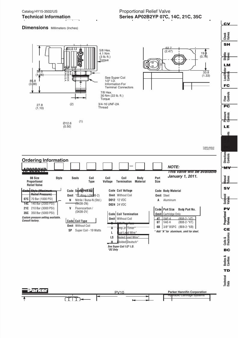
PV10
Technical Information
Seals CoilType
CoilTermination
Code Coil Voltage
Omit Without Coil
D012 12 VDC
D024 24 VDC
Code Seals / Kit No.
Omit “D”-Ring / (SK08-2)
N Nitrile / Buna-N (Std.)(SK08-2N)
V Fluorocarbon / (SK08-2V)
CoilVoltage
AP02B2YP
08 SizeProportionalRelief Valve
Style
Dimensions Millimeters (Inches)
Ordering Information
THIRD-ANGLEPROJECTION
Code Style (MaximumRelief Pressure)
07C 70 Bar (1000 PSI)
14C 140 Bar (2000 PSI)
21C 210 Bar (3000 PSI)
35C 350 Bar (5000 PSI)
Code Coil Type
Omit Without Coil
SP Super Coil - 19 Watts
Code Coil Termination
Omit Without Coil
D DIN Plug Face
A Amp Jr. Timer*
L Dual Lead Wire*
LS Sealed Lead Wire*H Molded Deutsch*
See Super Coil 1/2 ″ ″ ″ ″ ″ I.D.*DC Only
62.7(2.47)
19.8(0.78)
33.8(1.33)
X X V D C
X X W
C C X
X X X
H
MA DE I N U. S .A .
P A T .X X X X X X X
85.8(3.38)
27.8(1.10)
5/8 Hex.4.1 Nm(3 lb. ft.)
Torque
3/4-16 UNF-2AThread
7/8 Hex.30 Nm (22 lb. ft.)Torque
Ø12.6(0.50)
(1)
(2)
39.5(1.56)
See Super Coil1/2" I.D.Information ForTerminal Connectors
BodyMaterial
PortSize
Code Port Size Body Part No.
Omit Cartridge Only
4T SAE-4 (B08-2-*4T)6T SAE-6 (B08-2-*6T)
6B 3/8″ BSPG (B08-2-*6B)
* Add “A” for aluminum, omit for steel.
Code Body Material
Omit Steel
A Aluminum
Custom pressure setting available.Consult factory.
NOTE: This valve will be available
January 1, 2011.

8/16/2019 Parker Catálogo de Válvulas Proporcionales
http://slidepdf.com/reader/full/parker-catalogo-de-valvulas-proporcionales 12/62
Catalog HY15-3502/US
Parker Hannifin Corporation
Hydraulic Cartridge Systems
C h e c k
V a l v e s
S h u t t l e
V a l v
e s
L o a d / M o t o r
C o n t r o l s
F l o w
C o n t r o l s
P r e s
s u r e
C o n
t r o l s
L o g i c
E l e me n t s
D i r e c t i o n a l
C o n t r o l s
M a n u a l
V a l v e s
S o l e n o i d
V a l v e s
P r o p o r t i o n a l
V a l v e s
C o i l s &
E l e c t r o n i c s
B o d i e s &
C a v i t i e s
T e c h n i c a l
D a t a
SH
CV
LM
FC
PC
LE
DC
MV
SV
PV
CE
BC
TD
PV11
Proportional Relief ValveSeries AP04G2YP 10C, 21C, 35CTechnical Information
SpecificationsRated Flow 95 LPM (25 GPM)(At 300 PSI ∆∆∆∆∆P)When Coil is FullyDe-Energized
Factory Set Relief 10C 103 Bar (1500 PSI)Pressure When 21C 210 Bar (3000 PSI)Coil De-Energized 35C 350 Bar (5000 PSI)Measured at45 LPM (12 GPM)
Hysteresis @ < 7%250 Hz PWM of Maximum Pressure Setting
Response Time At To Unload 10ms75% of Nominal To LoadVoltage Change 10C 45 ms(Measured To 90% 21C 60 msof Press. Change) 35C 80 ms
Cartridge Material All parts steel. All operatingparts hardened steel.
Operating Temp. -40°C to +93.3°C (Nitrile)Range/Seals (-40°F to +200°F)
-31.7°C to +121.1°C (Fluorocarbon)(-25°F to +250°F)
Fluid Mineral-based or synthetic withCompatibility/ lubricating properties at viscositiesViscosity of 45 to 2000 SSU (6 to 420 cSt)
Filtration ISO Code 16/13,SAE Class 4 or better
Approx. Weight .14 kg (.31 lbs.)
Cavity C10-2(See BC Section for more details)
General Description
Proportional Relief Valve. Increasing Pressure With
Increasing Current. For additional information seeTechnical Tips on pages PV1-PV6.
Features
•Pilot operated spool-type design fits industry commoncavity (10-2)
• Relieving pressure output is proportional to DC currentinput
• Precise setting of factory preset pressure in energizedmode
• One piece cartridge housing ensures internalconcentricity
• Coil: Waterproof, hermetically sealed, requires noO’Rings; Symmetrical coil can be reversed withoutaffecting performance.
Performance Curves
PWM Current Regulator Recommended
(1) (2)
(1)
(2)
Flow (Q)
76
20
19
5
38
10
57
15
LPM
GPM0
95
25
0
2000
1000
300
205
137
68
21
3000
5000 345
2744000
PSI Bar
PressureDrop
(
P)
Hydraulic Oil 150 SSU @ 100°F (32 cSt)
Relief Performance
-35
-21
-10
Coil De-Energized
Coil Fully Energized
Hydraulic Oil 150 SSU @ 100°F (32 cSt)
0
1000
5000 345
205
274
137
68
Pressure3000
4000
PSI Bar
2000
Current, Amp
.30
.15
12V
24V
.60
.300
.90
.45
1.20
.60
Pressure vs. Input Current
-35
-21
-10
Measured at coil stabilizedtemperature and nominal flow

8/16/2019 Parker Catálogo de Válvulas Proporcionales
http://slidepdf.com/reader/full/parker-catalogo-de-valvulas-proporcionales 13/62
Catalog HY15-3502/US
Parker Hannifin Corporation
Hydraulic Cartridge Systems
Proportional Relief ValveSeries AP04G2YP 10C, 21C, 35C
PV12
Technical Information
Seals CoilType
CoilTermination
Code Seals / Kit. No.
N Nitrile / Buna-N (Std.)(SK30503N-1)
V Fluorocarbon / (SK30503V-1)
CoilVoltage
AP04G2YP
10 SizeProportionalRelief Valve
Style
Dimensions Millimeters (Inches)
Ordering Information
THIRD-ANGLEPROJECTION
Code Style (MaximumRelief Pressure)
10C 104 Bar (1500 PSI)
21C 210 Bar (3000 PSI)
35C 350 Bar (5000 PSI)
62.7(2.47)
19.8(0.78)
33.8(1.33)
7/8-14 UNF
15.8(0.62)
(1)
(2)
X X V D C
X X W
C C X
X X X
H
MA DE I N U. S .A .
P A T .X X X X X X X
97.6(3.84)
31.8(1.25)
10.0(0.40)
39.6(1.56)
5/8 Hex.4.1 Nm
(3 lb. ft.)Torque
1 Hex.34 Nm (25 lb. ft.)Torque
See Super Coil1/2" I.D.Information ForTerminal Connectors
BodyMaterial
PortSize
* Add “A” for aluminum, omit for steel.† Steel body only.
Code Port Size Body Part No.
Omit Cartridge Only
4P 1/4″ NPTF (B10-2-*4P)6P 3/8″ NPTF (B10-2-*6P)8P 1/2″ NPTF (B10-2-*8P)
6T SAE-6 (B10-2-*6T)8T SAE-8 (B10-2-*8T)
T8T SAE-8 (B10-2-T8T)†6B 3/8″ BSPG (B10-2-*6B)
Code Body Material
Omit Steel
A Aluminum
Custom pressure setting available.Consult factory.
Code Coil Voltage
Omit Without Coil
D012 12 VDC
D024 24 VDC
Code Coil Type
Omit Without Coil
SP Super Coil - 19 Watts
Code Coil Termination
Omit Without Coil
D DIN Plug Face
A Amp Jr. Timer*
L Dual Lead Wire*
LS Sealed Lead Wire*
H Molded Deutsch*
See Super Coil 1/2 ″ ″ ″ ″ ″ I.D.*DC Only

8/16/2019 Parker Catálogo de Válvulas Proporcionales
http://slidepdf.com/reader/full/parker-catalogo-de-valvulas-proporcionales 14/62
Catalog HY15-3502/US
Parker Hannifin Corporation
Hydraulic Cartridge Systems
C h e c k
V a l v e s
S h u t t l e
V a l v
e s
L o a d / M o t o r
C o n t r o l s
F l o w
C o n t r o l s
P r e s
s u r e
C o n
t r o l s
L o g i c
E l e me n t s
D i r e c t i o n a l
C o n t r o l s
M a n u a l
V a l v e s
S o l e n o i d
V a l v e s
P r o p o r t i o n a l
V a l v e s
C o i l s &
E l e c t r o n i c s
B o d i e s &
C a v i t i e s
T e c h n i c a l
D a t a
SH
CV
LM
FC
PC
LE
DC
MV
SV
PV
CE
BC
TD
PV13
Proportional Relief ValveSeries AP01B2YR 07A, 14A, 21A, 35ATechnical Information
Specifications
Rated Flow 07A 5.3 LPM (1.4 GPM)(At 70 PSI ∆∆∆∆∆P) 14A 3.4 LPM (0.9 GPM)
21A 3.0 LPM (0.8 GPM)35A 1.9 LPM (0.5 GPM)
Factory Set Relief 07A 70 Bar (1000 PSI)Pressure When 14A 140 Bar (2000 PSI)De-Energized 21A 210 Bar (3000 PSI)(±5% -Std. 35A 350 Bar (5000 PSI)±2% - Low
Variation)
Hysteresis @ < 10%200 Hz PWM
Cartridge Material All parts steel. All operatingparts hardened steel.
Operating Temp. -40°C to +93.3°C (Nitrile)Range/Seals (-40°F to +200°F)
-31.7°C to +121.1°C (Fluorocarbon)(-25°F to +250°F)
Fluid Mineral-based or synthetic withCompatibility/ lubricating properties at viscosities
Viscosity of 45 to 2000 SSU (6 to 420 cSt)
Filtration ISO Code 16/13,SAE Class 4 or better
Approx. Weight .09 kg (.19 lbs.)
Cavity 2G(See BC Section for more details)
General Description
Proportional Relief Valve. Decreasing Pressure With
Increasing Current. For additional information seeTechnical Tips on pages PV1-PV6.
Features• Analog Proportional Relief Valve regulates pressure
proportionally to the input solenoid current
• Direct acting poppet design
• One piece cartridge housing ensures internalconcentricity
• Coil: Waterproof, hermetically sealed, requires noO’Rings; Symmetrical coil can be reversed withoutaffecting performance.
Performance Curves
PWM Current Regulator Recommended
(1) (2)
(1)
(2)
Flow (Q)
2.84
.75
.95
.25
1.89
.50
LPM
GPM0
3.78
1.00
0
1000
137
68
2000
4000
5000
6000
274
345
414
2053000
PSI Bar
ReliefPressure
Hydraulic Oil 150 SSU @ 100°F (32 cSt)
Relief Performance
-21A
-14A
-07A
-35A
Hydraulic Oil 150 SSU @ 100°F (32 cSt)
0
4000
5000
274
345
137
205
68
Pressure
2000
3000
PSI Bar
1000
Input Current (%)
6020 400
80 100
Pressure vs. Input Current
Measured at coil stabilizedtemperature and nominal flow

8/16/2019 Parker Catálogo de Válvulas Proporcionales
http://slidepdf.com/reader/full/parker-catalogo-de-valvulas-proporcionales 15/62
Catalog HY15-3502/US
Parker Hannifin Corporation
Hydraulic Cartridge Systems
Proportional Relief ValveSeries AP01B2YR 07A, 14A, 21A, 35A
PV14
Technical Information
Seals CoilType
CoilTermination
Code Seals / Kit. No.
N Nitrile / Buna-N (Std.)(SK30129N-1)
V Fluorocarbon / (SK30129V-1)
E Ethylene Propylene
CoilVoltage
AP01B2YR
08 SizeProportionalRelief Valve
Style
Dimensions Millimeters (Inches)
Ordering Information
THIRD-ANGLEPROJECTION
Code Style (MaximumRelief Pressure)
07AL 70 Bar (1000 PSI)
14AL 140 Bar (2000 PSI)
21AL 210 Bar (3000 PSI)
35AL 350 Bar (5000 PSI)
Code Porting
324 1/4″ SAE
325 1/4″ BSP
Body MaterialPorting
Code Body Material
A Aluminum
S Steel
Line Body
LB10
Order Bodies Separately
22.0(0.86)
66.5(2.62)
36.0(1.43)
X X V D C
X X W
C A X
X X X
H
P A T .X X X X X X X
MA DE I N U. S .A .
5/8-18 UNF
12.7(0.50)
(2)
(1)
84.0(3.32)
26.0(1.02)
50.0(1.97)
25.4 Dia(1.00)Finger TightTorque
3/4 Hex.15 Nm (11 lb. ft.)Torque
See Super Coil5/8" I.D.Information ForTerminal Connectors
Code Coil Voltage
Omit Without Coil
D012 12 VDC
D024 24 VDC
Code Coil Type
Omit Without Coil
SP Super Coil - 28 Watts
Code Coil Termination
Omit Without Coil
D DIN Plug Face
A Amp Jr. Timer*
L Dual Lead Wire*
LS Sealed Lead Wire*
H Molded Deutsch*
See Super Coil 5/8 ″ ″ ″ ″ ″ I.D.*DC Only
NOTE: Requires 2G Cavity
Custom pressure setting available.Consult factory.

8/16/2019 Parker Catálogo de Válvulas Proporcionales
http://slidepdf.com/reader/full/parker-catalogo-de-valvulas-proporcionales 16/62
Catalog HY15-3502/US
Parker Hannifin Corporation
Hydraulic Cartridge Systems
C h e c k
V a l v e s
S h u t t l e
V a l v
e s
L o a d / M o t o r
C o n t r o l s
F l o w
C o n t r o l s
P r e s
s u r e
C o n
t r o l s
L o g i c
E l e me n t s
D i r e c t i o n a l
C o n t r o l s
M a n u a l
V a l v e s
S o l e n o i d
V a l v e s
P r o p o r t i o n a l
V a l v e s
C o i l s &
E l e c t r o n i c s
B o d i e s &
C a v i t i e s
T e c h n i c a l
D a t a
SH
CV
LM
FC
PC
LE
DC
MV
SV
PV
CE
BC
TD
PV15
Proportional Relief ValveSeries AP02B2YR 07A, 14A, 21A, 35ATechnical Information
Specifications
Rated Flow 07A 5.3 LPM (1.4 GPM)(At 70 PSI ∆∆∆∆∆P) 14A 3.4 LPM (0.9 GPM)
21A 3.0 LPM (0.8 GPM)35A 1.9 LPM (0.5 GPM)
Factory Set Relief 07A 70 Bar (1000 PSI)Pressure When 14A 140 Bar (2000 PSI)De-Energized 21A 210 Bar (3000 PSI)(±5% -Std. 35A 350 Bar (5000 PSI)±2% - Low
Variation)
Hysteresis @ < 10%200 Hz PWM
Cartridge Material All parts steel. All operatingparts hardened steel.
Operating Temp. -40°C to +93.3°C (Nitrile)Range/Seals (-40°F to +200°F)
-31.7°C to +121.1°C (Fluorocarbon)(-25°F to +250°F)
Fluid Mineral-based or synthetic withCompatibility/ lubricating properties at viscosities
Viscosity of 45 to 2000 SSU (6 to 420 cSt)
Filtration ISO Code 16/13,SAE Class 4 or better
Approx. Weight .09 kg (.19 lbs.)
Cavity C08-2(See BC Section for more details)
General Description
Proportional Relief Valve. Decreasing Pressure With
Increasing Current. For additional information seeTechnical Tips on pages PV1-PV6.
Features• Analog Proportional Relief Valve regulates pressure
proportionally to the input solenoid current
• Direct acting poppet design
• One piece cartridge housing ensures internalconcentricity
• Coil: Waterproof, hermetically sealed, requires noO’Rings; Symmetrical coil can be reversed withoutaffecting performance.
Performance Curves
PWM Current Regulator Recommended
(1) (2)
Flow (Q)
2.84
.75
.95
.25
1.89
.50
LPM
GPM0
3.78
1.00
0
1000
137
68
2000
4000
5000
6000
274
345
414
2053000
PSI Bar
ReliefPressure
Hydraulic Oil 150 SSU @ 100°F (32 cSt)
Relief Performance
-21A
-14A
-07A
-35A
Hydraulic Oil 150 SSU @ 100°F (32 cSt)
0
4000
5000
274
345
137
205
68
Press
ure
2000
3000
PSI Bar
1000
Input Current (%)
6020 400
80 100
Pressure vs. Input Current
Measured at coil stabilizedtemperature and nominal flow
(1)
(2)

8/16/2019 Parker Catálogo de Válvulas Proporcionales
http://slidepdf.com/reader/full/parker-catalogo-de-valvulas-proporcionales 17/62
Catalog HY15-3502/US
Parker Hannifin Corporation
Hydraulic Cartridge Systems
Proportional Relief ValveSeries AP02B2YR 07A, 14A, 21A, 35A
PV16
Technical Information
Seals CoilType
CoilTermination
Code Seals / Kit. No.
N Nitrile / Buna-N (Std.)
(SK30006N-1)V Fluorocarbon /
(SK30006V-1)
E Ethylene Propylene
CoilVoltage
AP02B2YR
08 SizeProportionalRelief Valve
Style
Dimensions Millimeters (Inches)
Ordering Information
THIRD-ANGLEPROJECTION
Code Style (MaximumRelief Pressure)
07AL 70 Bar (1000 PSI)
14AL 140 Bar (2000 PSI)
21AL 210 Bar (3000 PSI)
35AL 350 Bar (5000 PSI)
BodyMaterial
PortSize
Code Port Size Body Part No.
Omit Cartridge Only
4P 1/4″ NPTF (B08-2-*4P)6P 3/8″ NPTF (B08-2-*6P)
4T SAE-4 (B08-2-*4T)6T SAE-6 (B08-2-*6T)
6B 3/8″ BSPG (B08-2-*6B)
* Add “A” for aluminum, omit for steel.
Code Body Material
Omit Steel
A Aluminum
Code Coil Voltage
Omit Without Coil
D012 12 VDC
D024 24 VDC
Code Coil Type
Omit Without Coil
SP Super Coil - 28 Watts
Code Coil Termination
Omit Without Coil
D DIN Plug Face
A Amp Jr. Timer*
L Dual Lead Wire*
LS Sealed Lead Wire*
H Molded Deutsch*
See Super Coil 5/8 ″ ″ ″ ″ ″ I.D.*DC Only
22.0
(0.86)
66.5(2.62)
36.0(1.43)
X X V D C
X X W
C A X
X X X
H
P A T .X X X X X X X
MA DE I N U. S .A .
3/4 Hex.15 Nm (11 lb. ft.)Torque
(2)
(1)
93.3(3.67)
34.2(1.35)
50.0(1.97)
25.4 Dia(1.00)
Finger TightTorque
3/4-16 UNF
See Super Coil5/8" I.D.Information ForTerminal Connectors
Custom pressure setting available.Consult factory.

8/16/2019 Parker Catálogo de Válvulas Proporcionales
http://slidepdf.com/reader/full/parker-catalogo-de-valvulas-proporcionales 18/62
Catalog HY15-3502/US
Parker Hannifin Corporation
Hydraulic Cartridge Systems
C h e c k
V a l v e s
S h u t t l e
V a l v
e s
L o a d / M o t o r
C o n t r o l s
F l o w
C o n t r o l s
P r e s
s u r e
C o n
t r o l s
L o g i c
E l e me n t s
D i r e c t i o n a l
C o n t r o l s
M a n u a l
V a l v e s
S o l e n o i d
V a l v e s
P r o p o r t i o n a l
V a l v e s
C o i l s &
E l e c t r o n i c s
B o d i e s &
C a v i t i e s
T e c h n i c a l
D a t a
SH
CV
LM
FC
PC
LE
DC
MV
SV
PV
CE
BC
TD
PV17
Proportional Relief ValveSeries AP04G2YR 10C, 21C, 35CTechnical Information
SpecificationsRated Flow 95 LPM (25 GPM)(At 300 PSI ∆∆∆∆∆P)When Coil is FullyEnergized
Factory Set Relief 10C 103 Bar (1500 PSI)Pressure When 21C 210 Bar (3000 PSI)Coil De-Energized 35C 350 Bar (5000 PSI)Measured at45 LPM (12 GPM)
Hysteresis @ < 7%250 Hz PWM of Maximum Pressure Setting
Response Time At To Unload 45ms75% of Nominal To Load 25msVoltage Change(Measured To 90%of Press. Change)
Cartridge Material All parts steel. All operatingparts hardened steel.
Operating Temp. -40°C to +93.3°C (Nitrile)Range/Seals (-40°F to +200°F)
-31.7°C to +121.1°C (Fluorocarbon)(-25°F to +250°F)
Fluid Mineral-based or synthetic withCompatibility/ lubricating properties at viscositiesViscosity of 45 to 2000 SSU (6 to 420 cSt)
Filtration ISO Code 16/13,SAE Class 4 or better
Approx. Weight .14 kg (.30 lbs.)
Cavity C10-2(See BC Section for more details)
General Description
Proportional Relief Valve. Decreasing Pressure With
Increasing Current. For additional information seeTechnical Tips on pages PV1-PV6.
Features• Pilot operated spool-type design
• Precise setting of factory preset pressure in de-energizedmode
• One piece cartridge housing ensures internalconcentricity
• Coil: Waterproof, hermetically sealed, requires noO’Rings; Symmetrical coil can be reversed withoutaffecting performance.
Performance Curves
PWM Current Regulator Recommended
(1) (2)
(1)
(2)
Flow (Q)
76
20
19
5
38
10
57
15
LPM
GPM0
95
25
0
2000
1000
300
205
137
68
21
3000
5000 345
2744000
PSI Bar
R
eliefPressure
Hydraulic Oil 150 SSU @ 100°F (32 cSt)
Relief Performance
-35
-21
-10
Coil Fully Energized
Coil De-Energized
-35
-21
-10
Hydraulic Oil 150 SSU @ 100°F (32 cSt)
0
1000
5000 345
205
274
137
68
Pressure3000
4000
PSI Bar
2000
Input Current (%)
19 380
57 75
Pressure vs. Input Current

8/16/2019 Parker Catálogo de Válvulas Proporcionales
http://slidepdf.com/reader/full/parker-catalogo-de-valvulas-proporcionales 19/62
Catalog HY15-3502/US
Parker Hannifin Corporation
Hydraulic Cartridge Systems
Proportional Relief ValveSeries AP04G2YR 10C, 21C, 35C
PV18
Technical Information
Seals CoilType
CoilTermination
Code Seals / Kit. No.
N Nitrile / Buna-N (Std.)(SK30503N-1)
V Fluorocarbon / (SK30503V-1)
CoilVoltage
AP04G2YR
10 SizeProportionalRelief Valve
Style
Dimensions Millimeters (Inches)
Ordering Information
THIRD-ANGLEPROJECTION
Code Style (MaximumRelief Pressure)
10C 104 Bar (1500 PSI)
21C 210 Bar (3000 PSI)
35C 350 Bar (5000 PSI)
62.7(2.47)
19.8(0.78)
33.8(1.33)
7/8-14 UNF
15.8(0.62)
(1)
(2)
X X V D C
X X W
C C X
X X X
H
MA DE I N U. S .A .
P A T .X X X X X X X
89.7(3.53)
31.8(1.25)
10.0(0.40)
39.6(1.56)
3/4 Hex.4.1 Nm(3 lb. ft.)
Torque
1 Hex.34 Nm (25 lb. ft.)Torque
See Super Coil1/2" I.D.Information ForTerminal Connectors
BodyMaterial
PortSize
* Add “A” for aluminum, omit for steel.† Steel body only.
Code Port Size Body Part No.
Omit Cartridge Only
4P 1/4″ NPTF (B10-2-*4P)6P 3/8″ NPTF (B10-2-*6P)8P 1/2″ NPTF (B10-2-*8P)
6T SAE-6 (B10-2-*6T)8T SAE-8 (B10-2-*8T)
T8T SAE-8 (B10-2-T8T)†6B 3/8″ BSPG (B10-2-*6B)
Code Body Material
Omit Steel
A Aluminum
Code Coil Voltage
Omit Without Coil
D012 12 VDC
D024 24 VDC
Code Coil Type
Omit Without Coil
SP Super Coil - 19 Watts
Code Coil Termination
Omit Without Coil
D DIN Plug Face
A Amp Jr. Timer*
L Dual Lead Wire*
LS Sealed Lead Wire*
H Molded Deutsch*
See Super Coil 1/2 ″ ″ ″ ″ ″ I.D.*DC Only
Custom pressure setting available.Consult factory.
8/16/2019 Parker Catálogo de Válvulas Proporcionales
http://slidepdf.com/reader/full/parker-catalogo-de-valvulas-proporcionales 20/62
Catalog HY15-3502/US
Parker Hannifin Corporation
Hydraulic Cartridge Systems
C h e c k
V a l v e s
S h u t t l e
V a l v
e s
L o a d / M o t o r
C o n t r o l s
F l o w
C o n t r o l s
P r e s
s u r e
C o n
t r o l s
L o g i c
E l e me n t s
D i r e c t i o n a l
C o n t r o l s
M a n u a l
V a l v e s
S o l e n o i d
V a l v e s
P r o p o r t i o n a l
V a l v e s
C o i l s &
E l e c t r o n i c s
B o d i e s &
C a v i t i e s
T e c h n i c a l
D a t a
SH
CV
LM
FC
PC
LE
DC
MV
SV
PV
CE
BC
TD
PV19
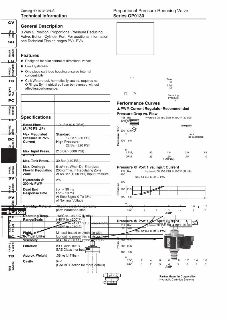
Proportional Pressure Reducing ValveSeries GP0130Technical Information
Specifications
Rated Flow 1.9 LPM (0.5 GPM)(At 70 PSI ∆∆∆∆∆P)
Max. Regulated StandardPressure @ 75% 17 Bar (250 PSI)Current High Pressure
22 Bar (320 PSI)
Max. Input Press. 210 Bar (3000 PSI)At Port 1
Max. Tank Press. 30 Bar (440 PSI)
Max. Drainage 5 cc/min. When De-EnergizedFlow In Regulating 200 cc/min. In Regulating ZoneZone At 68 Bar (1000 PSI) Input Pressure
Hysteresis @ 2%200 Hz PWM
Dead End t on = 30 msResponse Time t off = 10 ms
At Step Signal 0 To 75%of Nominal Voltage
Cartridge Material All parts steel. All operatingparts hardened steel.
Operating Temp. -40°C to +93.3°C (Nitrile)Range/Seals (-40°F to +200°F)
-31.7°C to +121.1°C (Fluorocarbon)(-25°F to +250°F)
Fluid Mineral-based or synthetic withCompatibility/ lubricating properties at viscositiesViscosity of 45 to 2000 SSU (6 to 420 cSt)
Filtration ISO Code 16/13,SAE Class 4 or better
Approx. Weight .08 kg (.17 lbs.)
Cavity 54-1(See BC Section for more details)
General Description
3 Way, 2 Position, Proportional Pressure Reducing
Valve. Bottom Cylinder Port. For additional informationsee Technical Tips on pages PV1-PV6.
Features• Designed for pilot control of directional valves
• Low Hysteresis
• One piece cartridge housing ensures internalconcentricity
• Coil: Waterproof, hermetically sealed, requires noO’Rings; Symmetrical coil can be reversed withoutaffecting performance.
Performance Curves
PWM Current Regulator Recommended
0
Pressure
100
500 34.0
20.5
27.4
13.6
6.8
300
400
PSI Bar
200
AMP
.2
.1
12V
24V
.4
.2
.6
.3
.8
.4
1.0
.50
1.2
.6
1.4
.7
1.6
.8
Hydraulic Oil 150 SSU @ 100°F (32 cSt)
Pressure @ Port 1 vs. Input Current
With 'SP' Coil @ 120 Hz PWM
0
Pressure
100
400 27.4
13.6
20.5
6.8
200
300
PSI Bar
AMP
.2
.1
12V
24V
.4
.2
.6
.3
.8
.40
1.0
.5
1.2
.6
Hydraulic Oil 150 SSU @ 100°F (32 cSt)Pressure @ Port 1 vs. Input Current
With 'SS' Coil @ 120 Hz PWM
Flow (Q)
2.9
.75
.95
.25
1.9
.50
LPM
GPM0
3.8
1.0
0
200
100
13.6
6.8
300 20.5PSI Bar
PressureDrop
Hydraulic Oil 150 SSU @ 100°F (32 cSt)
Pressure Drop vs. Flow
2 to 1Energized
1 to 3De-Eenergized
ReducingPressure
(1)
Inlet(2)
Tank(3)
(3) (2)
(1)

8/16/2019 Parker Catálogo de Válvulas Proporcionales
http://slidepdf.com/reader/full/parker-catalogo-de-valvulas-proporcionales 21/62
Catalog HY15-3502/US
Parker Hannifin Corporation
Hydraulic Cartridge Systems
Proportional Pressure Reducing ValveSeries GP0130
PV20
Technical Information
FilterScreen
OverrideOption
CoilType
CoilTermination
Code Filter Screen
Omit Not Required
F 60 Mesh Screen onInlet Port
CoilVoltage
GP01
08 SizeProportional
Valve
Style
Code Override Option
Omit If No M.O.
1 Manual Override
Dimensions Millimeters (Inches)
Ordering Information
THIRD-ANGLEPROJECTION
Code Style
30 Standard (‘SS’ Coil)
30 High Pressure(‘SP’ Coil)
Code Porting
591 1/4″ SAE
Body MaterialPorting
Code Body Material
A Aluminum
S Steel
Line Body
LB10
Order Bodies Separately
30
Code Seals / Kit No.
N Nitrile / Buna-N (Std.)(SK30122N-1)
V Fluorocarbon / (SK30122V-1)
Seals
62.7(2.47)
19.8(0.78)
33.8(1.33)
ManualOverride
M18X1.5
11.9(0.47)
(1)
(2)
(3)
X X V D C
X X W
C C X
X X X
H
MA DE I N U. S .A .
P A T .X X X X X X X
85.5(3.36)
27.8
(1.09)
5.6(0.22)
39.6(1.56)
9.70(0.38)
12.4(0.49)
FingerTightTorque
13/16 Hex.27 Nm (20 lb. ft.)Torque
See Super Coil1/2" I.D.Information ForTerminal Connectors
Code Coil Type
Omit Without Coil
SS Super Coil - 14 Watts
SP Super Coil - 19 Watts
Code Coil Voltage
Omit Without Coil
D012 12 VDC
D024 24 VDC
Code Coil Termination
Omit Without Coil
D DIN Plug Face
A Amp Jr. Timer*
L Dual Lead Wire*
LS Sealed Lead Wire*
H Molded Deutsch*
See Super Coil 1/2 ″ ″ ″ ″ ″ I.D.*DC Only
NOTE: Requires 54-1 Cavity

8/16/2019 Parker Catálogo de Válvulas Proporcionales
http://slidepdf.com/reader/full/parker-catalogo-de-valvulas-proporcionales 22/62
Catalog HY15-3502/US
Parker Hannifin Corporation
Hydraulic Cartridge Systems
C h e c k
V a l v e s
S h u t t l e
V a l v
e s
L o a d / M o t o r
C o n t r o l s
F l o w
C o n t r o l s
P r e s
s u r e
C o n
t r o l s
L o g i c
E l e me n t s
D i r e c t i o n a l
C o n t r o l s
M a n u a l
V a l v e s
S o l e n o i d
V a l v e s
P r o p o r t i o n a l
V a l v e s
C o i l s &
E l e c t r o n i c s
B o d i e s &
C a v i t i e s
T e c h n i c a l
D a t a
SH
CV
LM
FC
PC
LE
DC
MV
SV
PV
CE
BC
TD
PV21
Proportional Pressure Reducing ValveSeries GTP0234Technical Information
SpecificationsRated Flow 19 LPM (5 GPM)(At 70 PSI ∆∆∆∆∆P)
Max. Regulated 02 12/17 Bar (180/240 PSI)Pressure @ 75% 03 19/26 Bar (270/375 PSI)Current 05 31/40 Bar (450/580 PSI)(Using ‘SP’ Coil) 06 41/51 Bar (600/740 PSI)
09 65/79 Bar (940/1140 PSI)18 114/145 Bar (1650/2100 PSI)
Max. Input Press. 210 Bar (3000 PSI)At Port 3
Max. Drainage 100 cc/min. When De-EnergizedFlow In Regulating 750 cc/min. In Regulating Zone
Zone At 21 Bar (300 PSI) Input Pressure
Hysteresis @ 3.5%100 Hz PWM
Dead End 10 ms At Step SignalResponse Time 0 To 75% of Nominal Voltage
Cartridge Material All parts steel. All operatingparts hardened steel.
Operating Temp. -40°C to +93.3°C (Nitrile)Range/Seals (-40°F to +200°F)
-31.7°C to +121.1°C (Fluorocarbon)(-25°F to +250°F)
Fluid Mineral-based or synthetic with
Compatibility/ lubricating properties at viscositiesViscosity of 45 to 2000 SSU (6 to 420 cSt)
Filtration ISO Code 16/13,SAE Class 4 or better
Approx. Weight .08 kg (.17 lbs.)
Cavity C08-3(See BC Section for more details)
General Description
3 Way, 2 Position, Proportional Pressure Reducing
Valve. Side Cylinder Port. For additional informationsee Technical Tips on pages PV1-PV6.
Features• Minimal Hysteresis
• One piece cartridge housing ensures internalconcentricity
• Coil: Waterproof, hermetically sealed, requires noO’Rings; Symmetrical coil can be reversed withoutaffecting performance.
• Nonmagnetic spool and housing assembly
Performance Curves
PWM Current Regulator Recommended
(1) (3)
(2)
Tank(1)
ReducingPressure
(2)
Inlet(3)
2 to 1
3 to 2
Flow (Q)
15.2
4
3.8
1
7.6
2
11.4
3
LPM
GPM0
18.9
5
0
100
150
50
7.0
10.5
3.5
200 14.0PSI Bar
PressureDrop
Hydraulic Oil 150 SSU @ 100°F (32 cSt)
Pressure Drop vs. Flow
0
ControlPressure
100
600 41.4
20.7
27.4
34.5
13.8
6.9
300
400
500
PSI Bar
200
Current Amps
0.1
0.2
24V
12V
0.2
0.4
0.3
0.6
0.4
0.80
0.5
1.0
0.6
1.2
0.7
1.4
Hydraulic Oil 150 SSU @ 100°F (32 cSt)
Pressure @ Port 2 vs. Input Current
GTP0234 06
GTP0234 03
GTP0234 02
With 'SP' Coil @ 100 Hz PWM

8/16/2019 Parker Catálogo de Válvulas Proporcionales
http://slidepdf.com/reader/full/parker-catalogo-de-valvulas-proporcionales 23/62
Catalog HY15-3502/US
Parker Hannifin Corporation
Hydraulic Cartridge Systems
Proportional Pressure Reducing ValveSeries GTP0234
PV22
Technical Information
FilterScreen
OverrideOption
CoilType
CoilTermination
Code Filter Screen
1 60 Mesh Screen onInlet Port
CoilVoltage
GTP0234
08 SizeProportional
Valve
Style
Code Override Option
0 Not Required5 Detented M.O.
Dimensions Millimeters (Inches)
Ordering Information
THIRD-ANGLEPROJECTION
Code Style (Maximum RegulatedPressure Range - SP COIL)
02 12/17 Bar (180/240 PSI)
03 19/26 Bar (270/375 PSI)
05 31/40 Bar (450/580 PSI)
06 41/51 Bar (600/740 PSI)
09 65/79 Bar (940/1140 PSI)
18 114/145 Bar (1650/2100 PSI)
Code Seals / Kit No.
N Nitrile / Buna-N (Std.)(SK30081N-1)
V Fluorocarbon / (SK30081V-1)
Seals
1
62.7(2.47)
19.8(0.78)
33.8(1.33)
Manual Override(Infinite Control)
3/4-16 UNF
14.2(0.56)
(1)
(2)
(3)
X X V D C
X X W
C C X
X X X
H
MA DE I N U. S .A .
P A T .X X X X X X X
93.75(3.69)
40.21
(1.58)
5.59(0.22)
39.6(1.56)
13.21(0.52)
3/4 Hex.4.1 Nm(3 lb. ft.)Torque
7/8 Hex.27 Nm (20 lb. ft.)Torque
See Super Coil1/2" I.D.Information ForTerminal Connectors
PortSizeBodyMaterial
* Add “A” for aluminum, omit for steel.
Code Port Size Body Part No.
Omit Cartridge Only
4P 1/4″ NPTF (B08-3-*4P)
4T SAE-4 (B08-3-*4T)6T SAE-6 (B08-3-*6T)
6B 3/8″ BSPG (B08-3-*6B)
Code Body Material
Omit Steel
A Aluminum
Code Coil Voltage
Omit Without Coil
D012 12 VDC
D024 24 VDC
Code Coil Termination
Omit Without Coil
D DIN Plug Face
A Amp Jr. Timer*
L Dual Lead Wire*
LS Sealed Lead Wire*H Molded Deutsch*
See Super Coil 1/2 ″ ″ ″ ″ ″ I.D.*DC Only
Code Coil Type
Omit Without Coil
SS Super Coil - 14 Watts
SP Super Coil - 19 Watts

8/16/2019 Parker Catálogo de Válvulas Proporcionales
http://slidepdf.com/reader/full/parker-catalogo-de-valvulas-proporcionales 24/62
Catalog HY15-3502/US
Parker Hannifin Corporation
Hydraulic Cartridge Systems
C h e c k
V a l v e s
S h u t t l e
V a l v
e s
L o a d / M o t o r
C o n t r o l s
F l o w
C o n t r o l s
P r e s
s u r e
C o n
t r o l s
L o g i c
E l e me n t s
D i r e c t i o n a l
C o n t r o l s
M a n u a l
V a l v e s
S o l e n o i d
V a l v e s
P r o p o r t i o n a l
V a l v e s
C o i l s &
E l e c t r o n i c s
B o d i e s &
C a v i t i e s
T e c h n i c a l
D a t a
SH
CV
LM
FC
PC
LE
DC
MV
SV
PV
CE
BC
TD
PV23
Proportional Pressure Reducing ValveSeries GTP0434Technical Information
Specifications
Rated Flow 30 LPM (8 GPM)(At 70 PSI ∆∆∆∆∆P)
Max. Regulated 02 14/17 Bar (200/240 PSI)Pressure @ 75% 03 21/27 Bar (300/390 PSI)Current 05 29/38 Bar (420/550 PSI)(Using ‘SP’ Coil) 09 56/74 Bar (810/1080 PSI)
Max. Input Press. 210 Bar (3000 PSI)At Port 3
Max. Drainage 25 cc/min. When De-Energized
Flow In Regulating 800 cc/min. In Regulating ZoneZone At 21 Bar (300 PSI) Input Pressure
Hysteresis @ 3.5%200 Hz PWM
Dead End 40 ms At Step SignalResponse Time 0 To 75% of Nominal Voltage
Cartridge Material All parts steel. All operatingparts hardened steel.
Operating Temp. -40°C to +93.3°C (Nitrile)Range/Seals (-40°F to +200°F)
-31.7°C to +121.1°C (Fluorocarbon)(-25°F to +250°F)
Fluid Mineral-based or synthetic withCompatibility/ lubricating properties at viscositiesViscosity of 45 to 2000 SSU (6 to 420 cSt)
Filtration ISO Code 16/13,SAE Class 4 or better
Approx. Weight .13 kg (.28 lbs.)
Cavity 3X(See BC Section for more details)
General Description
3 Way, 2 Position, Proportional Pressure Reducing
Valve. Side Cylinder Port. For additional informationsee Technical Tips on pages PV1-PV6.
Features• Minimal Hysteresis
• One piece cartridge housing ensures internalconcentricity
• Coil: Waterproof, hermetically sealed, requires noO’Rings; Symmetrical coil can be reversed withoutaffecting performance.
• Nonmagnetic spool and housing assembly
Performance Curves
PWM Current Regulator Recommended
(1) (3)
(2)
Tank(1)
ReducingPressure
(2)
Inlet(3)
2 to 1
3 to 2
Flow (Q)
30.4
8
7.6
2
15.2
4
22.7
6
LPM
GPM0
37.8
10
0
100
150
50
7.0
10.5
3.5P
ressureDrop
200 14.0PSI Bar Hydraulic Oil 150 SSU @ 100°F (32 cSt)
Pressure Drop vs. Flow
0
ControlPres
sure
200
1000 69.0
41.4
55.2
27.6
13.8
600
800
PSI Bar
400
Current Amps
0.13
0.25
24V
12V
0.25
0.50
0.38
0.75
0.50
1.000
0.63
1.25
0.75
1.50
0.88
1.75
Hydraulic Oil 150 SSU @ 100°F (32 cSt)
Pressure @ Port 2 vs. Input Current
With 'SP' Coil @ 100 Hz PWMGTP04 3409
GTP04 3405
GTP04 3403
GTP04 3402

8/16/2019 Parker Catálogo de Válvulas Proporcionales
http://slidepdf.com/reader/full/parker-catalogo-de-valvulas-proporcionales 25/62
Catalog HY15-3502/US
Parker Hannifin Corporation
Hydraulic Cartridge Systems
Proportional Pressure Reducing ValveSeries GTP0434
PV24
Technical Information
FilterScreen
OverrideOption
CoilType
CoilTermination
Code Filter Screen
1 60 Mesh Screen onInlet Port
CoilVoltage
GTP0434
10 SizeProportional
Valve
Style
Code Override Option
0 Not Required
5 Detented M.O.
Dimensions Millimeters (Inches)
Ordering Information
THIRD-ANGLEPROJECTION
Code Style (Maximum RegulatedPressure Range - SP Coil)
02 14/17 Bar (200/240 PSI)
03 21/27 Bar (300/390 PSI)
05 29/38 Bar (420/550 PSI)
09 56/74 Bar (810/1080 PSI)
Code Porting
553 1/2″ SAE
554 3/8″ BSP
Body MaterialPorting
Code Body Material
A Aluminum
S Steel
Line Body
LB10
Order Bodies Separately
Code Seals / Kit No.
N Nitrile / Buna-N (Std.)(SK30081N-1)
V Fluorocarbon / (SK30081V-1)
Seals
1
Contact factory for other regulated pressure to 124 Bar (1800 PSI)
22.0(0.86)
66.5(2.62)
36.0(1.43)
X X V D C
X X W
C A X
X X X
H
P A T .X X X X X X X
MA DE I N U. S .A .
7/8-14 UNF
17.4(0.69)
(2)
(3)
(1)
112.8(4.44)
48.87(1.92)
5.54(0.22)
50.0(1.97)
13.21(0.52)
Manual Override(Infinite Control)
3/4 Hex.
4.1 Nm(3 lb. ft.)Torque
1 Hex.30 Nm (22 lb. ft.)Torque
See Super Coil5/8" I.D.Information ForTerminal Connectors
Code Coil Voltage
Omit Without Coil
D012 12 VDC
D024 24 VDC
Code Coil Type
Omit Without Coil
SS Super Coil - 18 Watts
SP Super Coil - 28 Watts
Code Coil Termination
Omit Without Coil
D DIN Plug Face
A Amp Jr. Timer*
L Dual Lead Wire*
LS Sealed Lead Wire*H Molded Deutsch*
See Super Coil 5/8 ″ ″ ″ ″ ″ I.D.*DC Only
NOTE: Requires 3X Cavity

8/16/2019 Parker Catálogo de Válvulas Proporcionales
http://slidepdf.com/reader/full/parker-catalogo-de-valvulas-proporcionales 26/62
Catalog HY15-3502/US
Parker Hannifin Corporation
Hydraulic Cartridge Systems
C h e c k
V a l v e s
S h u t t l e
V a l v
e s
L o a d / M o t o r
C o n t r o l s
F l o w
C o n t r o l s
P r e s
s u r e
C o n
t r o l s
L o g i c
E l e me n t s
D i r e c t i o n a l
C o n t r o l s
M a n u a l
V a l v e s
S o l e n o i d
V a l v e s
P r o p o r t i o n a l
V a l v e s
C o i l s &
E l e c t r o n i c s
B o d i e s &
C a v i t i e s
T e c h n i c a l
D a t a
SH
CV
LM
FC
PC
LE
DC
MV
SV
PV
CE
BC
TD
PV25
N.C. Proportional Flow Control ValveSeries DF122CTechnical Information
Performance Curves
General Description
Normally Closed Proportional Flow Control Valve.
For additional information see Technical Tipson pages PV1-PV6.
Features On-off type solenoids
• Low hysteresis
• PWM signal preferred
• Manual override standard
• All external parts zinc plated
Specifications
Rated Flow 53 LPM (14 GPM)Valve Fully Open
Maximum Inlet 210 Bar (3000 PSI)Pressure
Hysteresis 4%@ 200 Hz PWM
Cracking 20% - 30% of Input Signal(Dead band)
Frequency 100 - 400 Hz (200 Hz Preferred)
Maximum Control 12 VDC 24VDCCurrent 2.45A 1.23A
Cartridge Material All parts steel. All operatingparts hardened steel.
Operating Temp. -40°C to +93.3°C (Nitrile)Range/Seals (-40°F to +200°F)
-31.7°C to +121.1°C (Fluorocarbon)(-25°F to +250°F)
Fluid Mineral-based or synthetic withCompatibility/ lubricating properties at viscositiesViscosity of 45 to 2000 SSU (6 to 420 cSt)
Filtration ISO Code 16/13,
SAE Class 4 or better
Approx. Weight .32 kg (0.7 lbs.)
Cavity C12-2(See BC Section for more details)
Form Tool Rougher NoneFinisher NFT12-2F
(1)
(2)
Out(1)
In(2)
Hydraulic Oil 150 SSU @ 100°F (32 cSt)
Flow (Q)
19
5
38
10
LPM
GPM
057
15
76
20
Pressure Drop vs. Flow @ 100% Control Current
0
300 20.7
13.8
6.9
200
PSI Bar
100
PressureDrop(
P)
Hydraulic Oil 150 SSU @ 100°F (32 cSt)
Inlet Pressure
69
1000
Bar
PSI0
138
2000
207
3000
Flow vs. Inlet Pressure @ 100% Control Current
0
10
30 114
76
38
20
GPM LPM
Flow
(Q)
Hydraulic Oil 150 SSU @ 100°F (32 cSt)
0
15 57
19
38
Flow
(Q)
GPM LPM
5
10
Percent of Maximum Control Current
7525 500
100
Flow vs. Input Signal (Current)

8/16/2019 Parker Catálogo de Válvulas Proporcionales
http://slidepdf.com/reader/full/parker-catalogo-de-valvulas-proporcionales 27/62
Catalog HY15-3502/US
Parker Hannifin Corporation
Hydraulic Cartridge Systems
N.C. Proportional Flow Control ValveSeries DF122C
PV26
Technical Information
Dimensions Millimeters (Inches)
Ordering Information
THIRD-ANGLEPROJECTION
Seals CoilVoltage
CoilWattage
CoilTermination
BodyMaterial
PortSize
Code Coil Voltage
Omit Cartridge without Coil
D012 12 VDC
D024 24 VDC
Code Override Options
Omit Push Type withExtended Rod
Code Port Size Body Part No.
12P 3/4″ NTPF (B12-2-*12P)
8T SAE - 8 (B12-2-*8T)12T SAE - 12 (B12-2-*12T)
* Add “A” for aluminum, omit for steel.
Code Coil Termination
Omit Cartridge without Coil
D DIN
P Dual Spade
W Dual Wire
Code Coil Wattage
Omit Cartridgewithout Coil
H High Watt
Code Body Material
Omit Steel
A Aluminum
See DS Coil 1 ″ ″ ″ ″ ″ I.D.
DF122C14
12 Size NormallyClosed ProportionalFlow Control Valve
OverrideOptions
Code Seals / Kit. No.
Omit Nitrile / (SK12-2)
V Fluorocarbon / (SK12-2V)
60.0(2.35)
(1)
(2)
48.0(1.90)
FingerTight
Torque
17(.66)
Ø 22.2(.87)
1-1/16 - 12 UNF-2A
Thread
See DS Coil 1" I.D.Information ForTerminal Connectors
161.0(6.33)
41.3(1.63)
56.0(2.20)
1-1/4" Hex.29 Nm (21 lb. ft.)Torque

8/16/2019 Parker Catálogo de Válvulas Proporcionales
http://slidepdf.com/reader/full/parker-catalogo-de-valvulas-proporcionales 28/62

8/16/2019 Parker Catálogo de Válvulas Proporcionales
http://slidepdf.com/reader/full/parker-catalogo-de-valvulas-proporcionales 29/62
Catalog HY15-3502/US
Parker Hannifin Corporation
Hydraulic Cartridge Systems
N.C. Proportional Needle ValveSeries DF161C
PV28
Technical Information
Dimensions Millimeters (Inches)
Ordering Information
THIRD-ANGLEPROJECTION
Seals CoilVoltage
CoilTermination
BodyMaterial
PortSize
Code Coil Voltage
Omit Cartridge without Coil
D012 12 VDC
D024 24 VDC
Code Seals / Kit. No.
Omit Nitrile / (SK16-2)
V Fluorocarbon / (SK16-2V)
Code Port Size Body Part No.
12P 3/4″ NTPF (B16-2-*12P)16P 1″ NTPF (B16-2-*16P)
8T SAE - 8 (B16-2-*8T)12T SAE - 12 (B16-2-*12T)16T SAE - 16 (B16-2-*16T)
12B 3/4″ BSPG (B16-2-12B)†16B 1″ BSPG (B16-2-*16B)
* Add “A” for aluminum, omit for steel.† Steel body only.
Code Coil Termination
Omit Cartridge without Coil
D DIN
P Dual Spade
W Dual Wire
Code Body Material
Omit Steel
A Aluminum
See DS Coil 1 ″ ″ ″ ″ ″ I.D
DF161C40
16 Size NormallyClosed ProportionalFlow Control Valve
48.1(1.90)
59.8(2.35)
Outlet(1)
Inlet(2)
56.0(2.20)
44.4(1.75)
Ø 28.5(1.12)
136.8(5.38)
See DS Coil 1" I.D.Information ForTerminal Connectors
1-5/16 - 12 UN-2AThread
4.1 Nm(3 lb. ft.)Torque
1-1/2" Hex.54 Nm (40 lb. ft.)Torque

8/16/2019 Parker Catálogo de Válvulas Proporcionales
http://slidepdf.com/reader/full/parker-catalogo-de-valvulas-proporcionales 30/62
Catalog HY15-3502/US
Parker Hannifin Corporation
Hydraulic Cartridge Systems
C h e c k
V a l v e s
S h u t t l e
V a l v
e s
L o a d / M o t o r
C o n t r o l s
F l o w
C o n t r o l s
P r e s
s u r e
C o n
t r o l s
L o g i c
E l e me n t s
D i r e c t i o n a l
C o n t r o l s
M a n u a l
V a l v e s
S o l e n o i d
V a l v e s
P r o p o r t i o n a l
V a l v e s
C o i l s &
E l e c t r o n i c s
B o d i e s &
C a v i t i e s
T e c h n i c a l
D a t a
SH
CV
LM
FC
PC
LE
DC
MV
SV
PV
CE
BC
TD
PV29
N.C. Proportional Needle ValveSeries DF201CTechnical Information
Performance Curves
General Description
Normally Closed Proportional Needle Valve. This valve
is designed specifically for bleed off or unloadingcircuits. Back pressure will affect performance. Foradditional information see Technical Tips on pages
PV1-PV6.
Features
On-off type solenoids
• Low hysteresis
• PWM signal preferred
• All external parts zinc plated
Specifications
Rated Flow Low Watt 180 LPM (48 GPM)Valve Fully Open High Watt 227 LPM (60 GPM)
Maximum Inlet 210 Bar (3000 PSI)Pressure
Leakage at 125 cc/min. (7.6 in3 /min.)150 SSU (32 cSt)
Hysteresis 4%@ 200 Hz PWM
Cracking 20% - 30% of Input Signal
(Dead band)
Frequency 100 - 400 Hz (200 Hz Preferred)
Maximum Control 12 VDC 24VDCCurrent Low Watt 1.75A .91A
High Watt 2.45A 1.23A
Cartridge Material All parts steel. All operatingparts hardened steel.
Operating Temp. -40°C to +93.3°C (Nitrile)Range/Seals (-40°F to +200°F)
-31.7°C to +121.1°C (Fluorocarbon)(-25°F to +250°F)
Fluid Mineral-based or synthetic with
Compatibility/ lubricating properties at viscositiesViscosity of 45 to 2000 SSU (6 to 420 cSt)
Filtration ISO Code 16/13,SAE Class 4 or better
Approx. Weight .34 kg (0.75 lbs.)
Cavity C20-2(See BC Section for more details)
Form Tool Rougher NoneFinisher NFT20-2F
Flow vs. Input Signal (Current)Hydraulic Oil 150 SSU @ 100°F (32 cSt)
0
10
20
60 227
150
189
113
38
75
Flow
(Q)
40
50
GPM LPM
30
Current in Amps
2.0.5 1.0 1.5A 0 2.5 3.0
HighWatt @207 Bar(3000 PSI)LowWatt @
207 Bar (3000 PSI)
LowWatt @34.5 Bar (500 PSI)
HighWatt @34.5 Bar (500 PSI)
LowWatt
HighWatt
Hydraulic Oil 150 SSU @ 100°F (32 cSt)
Flow (Q)
189
50
38
10
113
30
151
40
76
20
LPM
GPM0
227
60
Pressure Drop vs. Flow @ 100% Current
0
100
500
400
36.2
29.0
21.7
14.5
7.2
300
PSI Bar
200
Pres
sureDrop(
P)
(2)
(1)
Inlet(2)
Outlet(1)

8/16/2019 Parker Catálogo de Válvulas Proporcionales
http://slidepdf.com/reader/full/parker-catalogo-de-valvulas-proporcionales 31/62
Catalog HY15-3502/US
Parker Hannifin Corporation
Hydraulic Cartridge Systems
N.C. Proportional Needle ValveSeries DF201C
PV30
Technical Information
Dimensions Millimeters (Inches)
Ordering Information
THIRD-ANGLEPROJECTION
Seals CoilVoltage
CoilWattage
CoilTermination
BodyMaterial
PortSize
Code Coil Voltage
Omit Cartridge without Coil
D012 12 VDC
D024 24 VDC
Code Seals / Kit. No.
Omit Nitrile / (SK20-2)
V Fluorocarbon / (SK20-2V)
Code Port Size Body Part No.
20T SAE - 20 (B20-2-*20T)
20B 1-1/4″ BSPG (B20-2-*20B)
* Add “A” for aluminum, omit for steel.
Code Coil Termination
Omit Cartridge without Coil
D DIN
P Dual Spade
W Dual Wire
Code Coil Wattage
Omit Cartridgewithout Coil
L Low Watt
H High Watt
Code Body Material
Omit Steel
A Aluminum
See DS Coil 1 ″ ″ ″ ″ ″ I.D.
DF201C60
20 Size NormallyClosed ProportionalFlow Control Valve
Inlet(2)
Outlet(1)
60.5(2.38)
48.3(1.90)
56.0(2.20)
See DS Coil 1" I.D.
Information ForTerminal Connectors
142.2(5.60)
55.1(2.17)
Ø 36.8(1.45)
1 5/8-12 UN-2AThread
4.1 Nm(3 lb. ft.)Torque
1-7/8" Hex.113 Nm (83 lb. ft.)Torque

8/16/2019 Parker Catálogo de Válvulas Proporcionales
http://slidepdf.com/reader/full/parker-catalogo-de-valvulas-proporcionales 32/62
Catalog HY15-3502/US
Parker Hannifin Corporation
Hydraulic Cartridge Systems
C h e c k
V a l v e s
S h u t t l e
V a l v
e s
L o a d / M o t o r
C o n t r o l s
F l o w
C o n t r o l s
P r e s
s u r e
C o n
t r o l s
L o g i c
E l e me n t s
D i r e c t i o n a l
C o n t r o l s
M a n u a l
V a l v e s
S o l e n o i d
V a l v e s
P r o p o r t i o n a l
V a l v e s
C o i l s &
E l e c t r o n i c s
B o d i e s &
C a v i t i e s
T e c h n i c a l
D a t a
SH
CV
LM
FC
PC
LE
DC
MV
SV
PV
CE
BC
TD
PV31
Proportional Flow Regulator ValveSeries HP02C 21Technical Information
Specifications
Rated Flow @ Standard (‘SS’ Coil)210 Bar (3000 PSI) 2 to 1 13.3 LPM (3.5 GPM)
1 to 2 9.5 LPM (2.5 GPM)High Flow (‘SP’ Coil)2 to 1 22.8 LPM (6.0 GPM)1 to 2 15.0 LPM (4.0 GPM)
Preferable Input Port 1Port For BestHysteresis
Hysteresis @ <10%100 Hz PWM
Cracking Pressure 25% of Input Current
Variation of Flow Standard Model@ 35% of Rated Up To ±20% Of Rated FlowCurrent & Constant Model “L”∆∆∆∆∆P Maintained By ±7% Of Rated FlowPressureCompensator
Cartridge Material All parts steel. All operatingparts hardened steel.
Operating Temp. -40°C to +93.3°C (Nitrile)Range/Seals (-40°F to +200°F)
-31.7°C to +121.1°C (Fluorocarbon)(-25°F to +250°F)
Fluid Mineral-based or synthetic withCompatibility/ lubricating properties at viscositiesViscosity of 45 to 2000 SSU (6 to 420 cSt)
Filtration ISO Code 16/13,SAE Class 4 or better
Approx. Weight .08 kg (.17 lbs.)
Cavity 2X(See BC Section for more details)
General Description
2 Way, Normally Closed, Proportional Flow Regulator
Valve. Partially Pressure Compensated. For additionalinformation see Technical Tips on pages PV1-PV6.
Features
•Analog Proportional Partially Pressure CompensatedFlow Regulator regulates flow proportionally to the inputsolenoid current.
• A low cost valve designed to be used in applicationswhere fine pressure compensation is not required.
• One piece cartridge housing ensures internalconcentricity
• Coil: Waterproof, hermetically sealed, requires noO’Rings; Symmetrical coil can be reversed withoutaffecting performance.
• Nonmagnetic spool and housing assembly
• Factory-adjusted low variation option (Model “L”) isavailable for applications where low variation of flow fromvalve to valve is essential at a given current or when an
external pressure compensator is used.
Performance Curves
PWM Current Regulator Recommended
Pressure
35
500
Bar
PSI
70
1000
105
15000
140
2000
175
2500
210
3000
0
F l o w 15.2
22.8
7.6
4
6
2
8 30.4GPM LPM Hydraulic Oil 150 SSU @ 100°F (32 cSt)
Flow Regulation (Measured at 75% of Rated Current)
2 to 1 ('SP' Coil)
1 to 2 ('SP' Coil)
2 to 1 ('SS' Coil)
1 to 2 ('SS' Coil)
Input Current (%)
8020 40 600
1000
4 15.2
2 7.6
6 22.8GPM LPM
F l o w
Hydraulic Oil 150 SSU @ 100°F (32 cSt)
Flow vs. Input Current
2 to 1 ('SP' Coil)
1 to 2 ('SP' Coil)
2 to 1 ('SS' Coil)
1 to 2 ('SS' Coil)
(2)
(1)
(1)
(2)

8/16/2019 Parker Catálogo de Válvulas Proporcionales
http://slidepdf.com/reader/full/parker-catalogo-de-valvulas-proporcionales 33/62
Catalog HY15-3502/US
Parker Hannifin Corporation
Hydraulic Cartridge Systems
Proportional Flow Regulator ValveSeries HP02C 21
PV32
Technical Information
FilterScreen
OverrideOption
CoilType
CoilTermination
Code Filter Screen
0 Not Available
CoilVoltage
HP02C
08 SizeProportional
Valve
Style
Code Override Option
0 Not Required
5 Detented M.O.(Infinite Control)
Dimensions Millimeters (Inches)
Ordering Information
THIRD-ANGLEPROJECTION
Code Style (MaximumRegulated Flow)
21 Standard (‘SS’ Coil)13.3 LPM (3.5 GPM)
21 High Flow (‘SP’ Coil)22.8 LPM (6.0 GPM)
Code Porting
513 3/8″ SAE
515 1/4″ BSP
Body MaterialPorting
Code Body Material
A Aluminum
S Steel
Line Body
LB10
Order Bodies Separately
Code Seals / Kit No.
N Nitrile / Buna-N (Std.)(SK30076N-1)
V Fluorocarbon / (SK30076V-1)
Seals
21
FlowVariation
Code Flow Variation
Omit Standard Up to ±20%of Rated Flow
L Low Variation(±7% of Rated Flow)
62.7(2.47)
19.8(0.78)
33.8(1.33)
Manual Override(Infinite Control)
3/4-16 UNF
15.9(0.63)
(1)
(2)
X X V D C
X X W
C C X
X X X
H
MA DE I N U. S .A .
P A T .X X X X X X X
82.04(3.23)
28.5
(1.12)
5.59(0.22)
39.6(1.56)
13.21(0.52)
3/4 Hex.4.1 Nm(3 lb. ft.)Torque
7/8 Hex.20 Nm (27 lb. ft.)Torque
See Super Coil1/2" I.D.Information ForTerminal Connectors
Code Coil Voltage
Omit Without Coil
D012 12 VDC
D024 24 VDC
Code Coil Type
Omit Without Coil
SS Super Coil - 14 Watts
SP Super Coil - 19 Watts
Code Coil Termination
Omit Without Coil
D DIN Plug Face
A Amp Jr. Timer*
L Dual Lead Wire*
LS Sealed Lead Wire*H Molded Deutsch*
See Super Coil 1/2 ″ ″ ″ ″ ″ I.D.*DC Only
NOTE: Requires 2X Cavity

8/16/2019 Parker Catálogo de Válvulas Proporcionales
http://slidepdf.com/reader/full/parker-catalogo-de-valvulas-proporcionales 34/62
Catalog HY15-3502/US
Parker Hannifin Corporation
Hydraulic Cartridge Systems
C h e c k
V a l v e s
S h u t t l e
V a l v
e s
L o a d / M o t o r
C o n t r o l s
F l o w
C o n t r o l s
P r e s
s u r e
C o n
t r o l s
L o g i c
E l e me n t s
D i r e c t i o n a l
C o n t r o l s
M a n u a l
V a l v e s
S o l e n o i d
V a l v e s
P r o p o r t i o n a l
V a l v e s
C o i l s &
E l e c t r o n i c s
B o d i e s &
C a v i t i e s
T e c h n i c a l
D a t a
SH
CV
LM
FC
PC
LE
DC
MV
SV
PV
CE
BC
TD
PV33
Proportional Flow Regulator ValveSeries JP02C 20, 21Technical Information
SpecificationsRated Flow 20 7.5 LPM (2 GPM)
Low Flow (‘SS’ Coil)21 15 LPM (4 GPM)
Standard (‘SS’ Coil)21 23 LPM (6 GPM)
High Flow (‘SP’ Coil)
Maximum Input 210 Bar (3000 PSI)Pressure At Port 2
Minimum Pressure 20 6.9 Bar (150 PSI) Low FlowDifferential 21 13.8 Bar (200 PSI) Standard
21 20.7 Bar (300 PSI) High Flow
Maximum Internal 570 cc (35 cu. in.)
Leakage @ 210 Bar (3000 PSI)
Hysteresis @ <10% (Low Flow and Standard)100 Hz PWM <3% (High Flow)
Cracking Pressure 25% of Input Signal
Variation of Flow Standard Model@ 35% of Rated Up To ±20% Of Rated FlowCurrent Model “L”
±7% Of Rated Flow
Cartridge Material All parts steel. All operatingparts hardened steel.
Operating Temp. -40°C to +93.3°C (Nitrile)Range/Seals (-40°F to +200°F)
-31.7°C to +121.1°C (Fluorocarbon)(-25°F to +250°F)
Fluid Mineral-based or synthetic withCompatibility/ lubricating properties at viscositiesViscosity of 45 to 2000 SSU (6 to 420 cSt)
Filtration ISO Code 16/13,SAE Class 4 or better
Approx. Weight .08 kg (.17 lbs.)
Cavity C08-3(See BC Section for more details)
General Description
2 Way, Normally Closed, Proportional Flow Regulator
Valve. Pressure Compensated. For additional informa-tion see Technical Tips on pages PV1-PV6.
Features
• One piece cartridge housing ensures internalconcentricity
• Coil: Waterproof, hermetically sealed, requires noO’Rings; Symmetrical coil can be reversed withoutaffecting performance.
• Nonmagnetic spool and housing assembly
• Factory-adjusted low variation option (Model “L”) isavailable for applications where low variation of flow fromvalve to valve is essential at a given current.
Performance CurvesPWM Current Regulator Recommended
(3)
(2)
Port (1)Is Not Used(3)
(2)
Flow
3.8
1
LPM
GPM
7.5
2
11.4
3
15.2
40
18.9
5
22.8
6
0
P r e s s u r e
100
13.8
20.7
6.9
200
300
PSI Bar Hydraulic Oil 150 SSU @ 100°F (32 cSt)Pressure Drop vs. Flow
JP02C 20('SS' Coil)
JP02C 21('SS' Coil)
JP02C 21('SP' Coil)
Measured when valve is fully open@ 75% of rated current
0
F l o w
2
15.2
22.8
7.6
4
6
GPM LPM
Pressure
35
500
Bar
PSI
70
1000
105
1500
140
20000
175
2500
210
3000
Hydraulic Oil 150 SSU @ 100°F (32 cSt)
Flow Regulation (Measured 75% of Rated Current)
JP02C 21 ('SP' Coil)
JP02C 21 ('SS' Coil)
JP02C 20 ('SS' Coil)
Input Current (%)
8020 40 600
1000
4
2
15.2
7.6
6 22.8GPM LPM
F l o w
Hydraulic Oil 150 SSU @ 100°F (32 cSt)
Flow vs. Input Current
JP02C 20('SS' Coil)
JP02C 21 ('SP' Coil)
JP02C 21('SS' Coil)

8/16/2019 Parker Catálogo de Válvulas Proporcionales
http://slidepdf.com/reader/full/parker-catalogo-de-valvulas-proporcionales 35/62
Catalog HY15-3502/US
Parker Hannifin Corporation
Hydraulic Cartridge Systems
Proportional Flow Regulator ValveSeries JP02C 20, 21
PV34
Technical Information
FilterScreen
OverrideOption
CoilType
CoilTermination
Code Filter Screen
0 Not Available
1 60 Mesh Screen onPort 2
CoilVoltage
JP02C
08 SizeProportional
Valve
Style
Code Override Option
0 Not Required
5 Detented M.O.(Infinite Control)
Dimensions Millimeters (Inches)
Ordering Information
THIRD-ANGLEPROJECTION
Code Style (MaximumRegulated Flow)
20 Low Flow (‘SS’ Coil)7.5 LPM (2 GPM)
21 Standard (‘SS’ Coil)15 LPM (4 GPM)
21 High Flow (‘SP’ Coil)23 LPM (6 GPM)
Code Seals / Kit No.
N Nitrile / Buna-N (Std.)(SK30105N-1)
V Fluorocarbon / (SK30105V-1)
Seals FlowVariation
Code Flow Variation
Omit Standard Up to ±20%of Rated Flow
L Low Variation(±7% of Rated Flow)
62.7(2.47)
19.8(0.78)
33.8(1.33)
Manual Override(Infinite Control)
3/4-16 UNF
14.2(0.56)
(3)
(2)
X X V D C
X X W
C C X
X X X
H
MA DE I N U. S .A .
P A T .X X X X X X X
96.04(3.78)
42.5(1.67)
5.54(0.22)
39.6(1.56)
13.21(0.52)
3/4 Hex.4.1 Nm(3 lb. ft.)Torque
7/8 Hex.27 Nm (20 lb. ft.)Torque
See Super Coil1/2" I.D.Information ForTerminal Connectors
PortSize
BodyMaterial
* Add “A” for aluminum, omit for steel.
Code Port Size Body Part No.
Omit Cartridge Only
4P 1/4″ NPTF (B08-3-*4P)
4T SAE-4 (B08-3-*4T)6T SAE-6 (B08-3-*6T)
6B 3/8″ BSPG (B08-3-*6B)
Code Body Material
Omit Steel
A Aluminum
Code Coil Voltage
Omit Without Coil
D012 12 VDC
D024 24 VDC
Code Coil Termination
Omit Without Coil
D DIN Plug Face
A Amp Jr. Timer*
L Dual Lead Wire*
LS Sealed Lead Wire*
H Molded Deutsch*
See Super Coil 1/2 ″ ″ ″ ″ ″ I.D.*DC Only
Code Coil Type
Omit Without CoilSS Super Coil - 14 Watts
SP Super Coil - 19 Watts

8/16/2019 Parker Catálogo de Válvulas Proporcionales
http://slidepdf.com/reader/full/parker-catalogo-de-valvulas-proporcionales 36/62
Catalog HY15-3502/US
Parker Hannifin Corporation
Hydraulic Cartridge Systems
C h e c k
V a l v e s
S h u t t l e
V a l v
e s
L o a d / M o t o r
C o n t r o l s
F l o w
C o n t r o l s
P r e s
s u r e
C o n
t r o l s
L o g i c
E l e me n t s
D i r e c t i o n a l
C o n t r o l s
M a n u a l
V a l v e s
S o l e n o i d
V a l v e s
P r o p o r t i o n a l
V a l v e s
C o i l s &
E l e c t r o n i c s
B o d i e s &
C a v i t i e s
T e c h n i c a l
D a t a
SH
CV
LM
FC
PC
LE
DC
MV
SV
PV
CE
BC
TD
PV35
Proportional Flow Regulator ValveSeries HP04C 21Technical Information
Specifications
Rated Flow Standard (‘SS’ Coil)2 to 1 @ 30 LPM (8 GPM)210 Bar (3000 PSI) High Flow (‘SP’ Coil)
36 LPM (9.5 GPM)
Preferable Input Port 1Port For BestHysteresis
Hysteresis @ <10%
100 Hz PWMCracking Pressure 21% of Rated Current (Standard)
17% of Rated Current (High Flow)
Variation of Flow Standard Model@ 35% of Rated Up To ±5% Of Rated FlowCurrent & Constant Model “L”∆∆∆∆∆P Maintained By ±2% Of Rated FlowPressureCompensator
Cartridge Material All parts steel. All operatingparts hardened steel.
Operating Temp. -40°C to +93.3°C (Nitrile)Range/Seals (-40°F to +200°F)
-31.7°C to +121.1°C (Fluorocarbon)(-25°F to +250°F)
Fluid Mineral-based or synthetic withCompatibility/ lubricating properties at viscositiesViscosity of 45 to 2000 SSU (6 to 420 cSt)
Filtration ISO Code 16/13,SAE Class 4 or better
Approx. Weight .12 kg (.26 lbs.)
Cavity C10-2(See BC Section for more details)
General Description
2 Way, Normally Closed, Proportional Flow Regulator
Valve. Partially Pressure Compensated. For additionalinformation see Technical Tips on pages PV1-PV6.
Features
•Analog Proportional Partially Pressure CompensatedFlow Regulator regulates flow proportionally to the inputsolenoid current.
• A low cost valve designed to be used in applicationswhere fine pressure compensation is not required.
• One piece cartridge housing ensures internalconcentricity
• Coil: Waterproof, hermetically sealed, requires noO’Rings; Symmetrical coil can be reversed withoutaffecting performance.
• Nonmagnetic spool and housing assembly
• Factory-adjusted low variation option (Model “L”) isavailable for applications where low variation of flow fromvalve to valve is essential at a given current or when anexternal pressure compensator is used.
Performance Curves
PWM Current Regulator Recommended
'SP' Coil
'SS' Coil
Input Current (%)
8020 40 600
1000
12 45.6
4
8
15.2
30.4
16 60.8GPM LPM
F l o w
Hydraulic Oil 150 SSU @ 100°F (32 cSt)
Flow vs. Input Current
Pressure
35
500
Bar
PSI
70
1000
105
15000
140
2000
175
2500
210
3000
0
F l o w
30.4
45.6
15.2
8
12
4
16 60.8GPM LPM Hydraulic Oil 150 SSU @ 100°F (32 cSt)
Flow Regulation
2 to 1
1 to 2
Measured 75% of ratedcurrent with 'SP' Coil
(2)
(1)
(1)
(2)

8/16/2019 Parker Catálogo de Válvulas Proporcionales
http://slidepdf.com/reader/full/parker-catalogo-de-valvulas-proporcionales 37/62
Catalog HY15-3502/US
Parker Hannifin Corporation
Hydraulic Cartridge Systems
Proportional Flow Regulator ValveSeries HP04C 21
PV36
Technical Information
FilterScreen
OverrideOption
CoilType
CoilTermination
Code Filter Screen
0 Not Available
CoilVoltage
HP04C
10 SizeProportional
Valve
Style
Code Override Option
0 Not Required
5 Detented M.O.(Infinite Control)
Dimensions Millimeters (Inches)
Ordering Information
THIRD-ANGLEPROJECTION
Code Style (MaximumRegulated Flow)
21 Standard (‘SS’ Coil)30 LPM (8 GPM)
21 High Flow (‘SP’ Coil)36 LPM (9.5 GPM)
Code Seals / Kit No.
N Nitrile / Buna-N (Std.)(SK30503N-1)
V Fluorocarbon / (SK30503V-1)
Seals
21
OpeningPoint
Variation
Code Flow Variation
Omit Standard Up to ±5%of Current
L Low Variation(±2% of Current Flow)
22.0(0.86)
66.5(2.62)
36.0(1.43)
X X V D C
X X W
C A X
X X X
H
P A T .X X X X X X X
MA DE I N U. S .A .
7/8-14 UNF
15.8(0.62)
(2)
(1)
96.5(3.80)
33.3(1.31)
5.60(0.22)
50.0(1.97)
13.72(0.54)
7.88(0.31)
4.0(0.16)
Manual Override(Infinite Control)
Stroke
3/4 Hex.4.1 Nm(3 lb. ft.)Torque
1 Hex.30 Nm (22 lb. ft.)Torque
See Super Coil5/8" I.D.Information ForTerminal Connectors
BodyMaterial
PortSize
* Add “A” for aluminum, omit for steel.† Steel body only.
Code Port Size Body Part No.
Omit Cartridge Only
4P 1/4″ NPTF (B10-2-*4P)6P 3/8″ NPTF (B10-2-*6P)8P 1/2″ NPTF (B10-2-*8P)
6T SAE-6 (B10-2-*6T)8T SAE-8 (B10-2-*8T)
T8T SAE-8 (B10-2-T8T)†6B 3/8″ BSPG (B10-2-*6B)
Code Body Material
Omit Steel
A Aluminum
Code Coil Voltage
Omit Without Coil
D012 12 VDC
D024 24 VDC
Code Coil Termination
Omit Without Coil
D DIN Plug Face
A Amp Jr. Timer*
L Dual Lead Wire*
LS Sealed Lead Wire*H Molded Deutsch*
See Super Coil 5/8 ″ ″ ″ ″ ″ I.D.*DC Only
Code Coil Type
Omit Without Coil
SS Super Coil - 18 Watts
SP Super Coil - 28 Watts

8/16/2019 Parker Catálogo de Válvulas Proporcionales
http://slidepdf.com/reader/full/parker-catalogo-de-valvulas-proporcionales 38/62
Catalog HY15-3502/US
Parker Hannifin Corporation
Hydraulic Cartridge Systems
C h e c k
V a l v e s
S h u t t l e
V a l v
e s
L o a d / M o t o r
C o n t r o l s
F l o w
C o n t r o l s
P r e s
s u r e
C o n
t r o l s
L o g i c
E l e me n t s
D i r e c t i o n a l
C o n t r o l s
M a n u a l
V a l v e s
S o l e n o i d
V a l v e s
P r o p o r t i o n a l
V a l v e s
C o i l s &
E l e c t r o n i c s
B o d i e s &
C a v i t i e s
T e c h n i c a l
D a t a
SH
CV
LM
FC
PC
LE
DC
MV
SV
PV
CE
BC
TD
PV37
Proportional Flow Regulator ValveSeries JP04C 21Technical Information
Specifications
Rated Flow 21 30 LPM (8 GPM)Standard (‘SS’ Coil)
21 36 LPM (9.5 GPM)High Flow (‘SP’ Coil)
Maximum Input 210 Bar (3000 PSI)Pressure At Port 2
Minimum Pressure 21 13.8 Bar (200 PSI) StandardDifferential 21 20.7 Bar (300 PSI) High Flow
Maximum Internal 780 cc (46 cu. in.)
Leakage @ 210 Bar (3000 PSI)
Hysteresis @ 7%100 Hz PWM
Cracking Pressure 25% of Input Signal
Variation of Flow Standard Model@ 35% of Rated Up To ±20% Of Rated FlowCurrent Model “L”
±7% Of Rated Flow
Cartridge Material All parts steel. All operatingparts hardened steel.
Operating Temp. -40°C to +93.3°C (Nitrile)Range/Seals (-40°F to +200°F)
-31.7°C to +121.1°C (Fluorocarbon)(-25°F to +250°F)
Fluid Mineral-based or synthetic withCompatibility/ lubricating properties at viscositiesViscosity of 45 to 2000 SSU (6 to 420 cSt)
Filtration ISO Code 16/13,SAE Class 4 or better
Approx. Weight .13 kg (.28 lbs.)
Cavity 3X(See BC Section for more details)
General Description
2 Way, Normally Closed, Proportional Flow Regulator
Valve. Pressure Compensated. For additional informa-tion see Technical Tips on pages PV1-PV6.
Features• One piece cartridge housing ensures internal
concentricity
• Coil: Waterproof, hermetically sealed, requires noO’Rings; Symmetrical coil can be reversed withoutaffecting performance.
• Nonmagnetic spool and housing assembly
• Factory-adjusted low variation option (Model “L”) isavailable for applications where low variation of flow fromvalve to valve is essential at a given current.
Performance CurvesPWM Current Regulator Recommended
(3)
(2)
(3)
(2)
Port (1)Is Not Used
Flow
7.6
2
LPM
GPM
15.2
4
22.7
6
30.4
80
37.8
10
45.0
12
0
P r e s s u r e
100
13.8
20.7
6.9
200
300
PSI Bar Hydraulic Oil 150 SSU @ 100°F (32 cSt)
Pressure Drop vs. Flow
'SS' Coil
'SP'Coil
Measured when valve is fully open@ 75% of rated current
"SS" Coil
"SP" Coil
Input Current (%)
8020 40 600
1000
8
4
30.3
15.1
12 45.4GPM LPM
F l o w
Hydraulic Oil 150 SSU @ 100°F (32 cSt)
Flow vs. Input Signal
0
F l o w
4
30.3
45.4
15.1
8
12
GPM LPM
Pressure
35
500
Bar
PSI
70
1000
105
1500
140
20000
175
2500
210
3000
Hydraulic Oil 150 SSU @ 100°F (32 cSt)
Flow Regulation (Measured 75% of Rated Current)
JP04C 21 ("SP" Coil)
JP04C 21 ("SS" Coil)

8/16/2019 Parker Catálogo de Válvulas Proporcionales
http://slidepdf.com/reader/full/parker-catalogo-de-valvulas-proporcionales 39/62
Catalog HY15-3502/US
Parker Hannifin Corporation
Hydraulic Cartridge Systems
Proportional Flow Regulator ValveSeries JP04C 21
PV38
Technical Information
FilterScreen
OverrideOption
CoilType
CoilTermination
Code Filter Screen
0 Not Required
1 60 Mesh Screen onPort 2
CoilVoltage
JP04C
10 SizeProportional
Valve
Style
Code Override Option
0 Not Required
5 Detented M.O.(Infinite Control)
Dimensions Millimeters (Inches)
Ordering Information
THIRD-ANGLEPROJECTION
Code Style (MaximumRegulated Flow)
21 Standard (‘SS’ Coil)30 LPM (8 GPM)
21 High Flow (‘SP’ Coil)36 LPM 9.5 GPM)
Code Porting
553 1/2″ SAE
554 3/8″ BSP
Body MaterialPorting
Code Body Material
A Aluminum
S Steel
Line Body
LB10
Order Bodies Separately
Code Seals / Kit No.
N Nitrile / Buna-N (Std.)(SK30106N-1)
V Fluorocarbon / (SK30106V-1)
Seals FlowVariation
Code Flow Variation
Omit Standard Up to ±20%of Rated Flow
L Low Variation(±7% of Rated Flow)
21
22.0(0.86)
66.5(2.62)
36.0(1.43)
X X V D C
X X W
C A X
X X X
H
P A T .X X X X X X X
MA DE I N U. S .A .
7/8-14 UNF
17.4(0.68)
(2)
(3)
115.7(4.55)
51.79(2.04)
5.51(0.22)
50.0(1.97)
13.21(0.52)
Manual Override(Infinite Control)
3/4 Hex.
4.1 Nm(3 lb. ft.)Torque
1 Hex.30 Nm (22 lb. ft.)Torque
See Super Coil5/8" I.D.Information ForTerminal Connectors
Code Coil Voltage
Omit Without Coil
D012 12 VDC
D024 24 VDC
Code Coil Type
Omit Without Coil
SS Super Coil - 18 Watts
SP Super Coil - 28 Watts
Code Coil Termination
Omit Without Coil
D DIN Plug Face
A Amp Jr. Timer*
L Dual Lead Wire*
LS Sealed Lead Wire*
H Molded Deutsch*
See Super Coil 5/8 ″ ″ ″ ″ ″ I.D.*DC Only
NOTE: Requires 3X Cavity

8/16/2019 Parker Catálogo de Válvulas Proporcionales
http://slidepdf.com/reader/full/parker-catalogo-de-valvulas-proporcionales 40/62
Catalog HY15-3502/US
Parker Hannifin Corporation
Hydraulic Cartridge Systems
C h e c k
V a l v e s
S h u t t l e
V a l v
e s
L o a d / M o t o r
C o n t r o l s
F l o w
C o n t r o l s
P r e s
s u r e
C o n
t r o l s
L o g i c
E l e me n t s
D i r e c t i o n a l
C o n t r o l s
M a n u a l
V a l v e s
S o l e n o i d
V a l v e s
P r o p o r t i o n a l
V a l v e s
C o i l s &
E l e c t r o n i c s
B o d i e s &
C a v i t i e s
T e c h n i c a l
D a t a
SH
CV
LM
FC
PC
LE
DC
MV
SV
PV
CE
BC
TD
PV39
Proportional Flow Regulator ValveSeries DFA125C21Technical Information
Specifications
Rated Flow @ 75% 56.8 LPM (15 GPM)of Rated Current Requires (‘SP’ Coil)
Maximum Input 210 Bar (3000 PSI)Pressure At Port 2
Minimum Pressure 20.7 Bar (300 PSI)Differential
Maximum Internal 568 cc (35 cu. in.)Leakage @ 210 Bar (3000 PSI)
Hysteresis @ >15%100 Hz PWM
Cartridge Material All parts steel. All operatingparts hardened steel.
Operating Temp. -40°C to +93.3°C (Nitrile)Range/Seals (-40°F to +200°F)
-31.7°C to +121.1°C (Fluorocarbon)(-25°F to +250°F)
Fluid Mineral-based or synthetic withCompatibility/ lubricating properties at viscositiesViscosity of 45 to 2000 SSU (6 to 420 cSt)
Filtration ISO Code 16/13,SAE Class 4 or better
Approx. Weight .40 kg (.89 lbs.)
Cavity C12-3L(See BC Section for more details)
General Description
2 Way, Normally Closed, Proportional Flow Regulator
Valve. Pressure Compensated. For additional informa-tion see Technical Tips on pages PV1-PV6.
Features• One piece cartridge housing ensures internal
concentricity
• Coil: Waterproof, hermetically sealed, requires noO’Rings; Symmetrical coil can be reversed withoutaffecting performance.
NOTE:
This valve will be available January 1, 2011.
Performance Curves
PWM Current Regulator Recommended
(3)
(2) (3)
(2)
Port (1)Is Not Used
Input Current (%)
25 500
75
Hydraulic Oil 150 SSU @ 100°F (32 cSt)
0
3
6
34.2
45.6
57.0
76.0
11.4
22.8
9
12
15
20GPM LPM
Flow
Flow vs. Input Current
Hydraulic Oil 150 SSU @ 100°F (32 cSt)
0
100
13.9
6.9
200
PSI Bar
PressureDifferential
Pressure Drop vs. Flow (Through cartridge only)
Flow (Q)
30.4
8
15.2
4
LPM
GPM0
45.5
12
60.8
16
2-3 ENERGIZED@ 75% of Rated Current
Load Pressure
Bar
PSI
70
10000
140
2000
210
3000
Hydraulic Oil 150 SSU @ 100°F (32 cSt)
0
12
15
3
6
9
45.6
57.0
11.4
22.8
34.2
20 76.0GPM LPM
Flow
Pressure Compensation of Regulated Flow

8/16/2019 Parker Catálogo de Válvulas Proporcionales
http://slidepdf.com/reader/full/parker-catalogo-de-valvulas-proporcionales 41/62
Catalog HY15-3502/US
Parker Hannifin Corporation
Hydraulic Cartridge Systems
Proportional Flow Regulator ValveSeries DFA125C21
PV40
Technical Information
OverrideOption
CoilType
CoilTermination
CoilVoltage
DFA125C
12 SizeProportional
Valve
Style
Code Override Option
Omit Not Available
S Standard M.O.(Infinite Control)
Dimensions Millimeters (Inches)
Ordering Information
THIRD-ANGLEPROJECTION
Code Style (MaximumRegulated Flow)
21 High Flow (‘SP’ Coil)56.8 LPM (15 GPM)
Code Port Size
12T SAE - 12
BodyMaterial
3-WayLong Cavity
Code Body Material
A Aluminum
12 Size
B12
Order Bodies Separately
Code Seals / Kit No.
N Nitrile / Buna-N (Std.)(SK12-3LN)
V Fluorocarbon / (SK12-3LV)
Seals
21
Code Coil Type
Omit Without Coil
SP Super Coil - 28 Watts
Code Coil Voltage
Omit Without Coil
D012 12 VDC
D024 24 VDC
Code Coil Termination
Omit Without Coil
D DIN Plug Face
A Amp Jr. Timer*
S Dual Spade*
L Dual Lead Wire*
LS Sealed Lead Wire*
H Molded Deutsch*See Super Coil 5/8 ″ ″ ″ ″″ I.D.*DC Only
Port Size
3L A 12T
S
66.5(2.62)
22.0(0.86)
36.0(1.43)
XXVDC
XXW
CAX
XXX
H
PAT.XXXXXXX
MADEINU.S.A.
(1)
(3)
(2)
1-1/16-12UN-2AThread
Manual Override(Infinite Control)
15.7 (0.62)
8.7(0.34)
2.5(0.10)
50.0(1.97)
175.8(6.92)
76.2(3.00)
22.2(0.87)
99.5(3.92)
4.8(0.19)
19.1(0.75)
Finger Tight to
4.1 Nm (3 lb.ft.)Max.
1-1/4" Hex.74 Nm (55 lb. ft.)Torque
See Super Coil5/8" I.D.Information ForTerminal Connectors
NOTE: This valve will be available
January 1, 2011.

8/16/2019 Parker Catálogo de Válvulas Proporcionales
http://slidepdf.com/reader/full/parker-catalogo-de-valvulas-proporcionales 42/62
Catalog HY15-3502/US
Parker Hannifin Corporation
Hydraulic Cartridge Systems
C h e c k
V a l v e s
S h u t t l e
V a l v
e s
L o a d / M o t o r
C o n t r o l s
F l o w
C o n t r o l s
P r e s
s u r e
C o n
t r o l s
L o g i c
E l e me n t s
D i r e c t i o n a l
C o n t r o l s
M a n u a l
V a l v e s
S o l e n o i d
V a l v e s
P r o p o r t i o n a l
V a l v e s
C o i l s &
E l e c t r o n i c s
B o d i e s &
C a v i t i e s
T e c h n i c a l
D a t a
SH
CV
LM
FC
PC
LE
DC
MV
SV
PV
CE
BC
TD
PV41
Proportional Flow Regulator ValveSeries HP02P 21Technical Information
Specifications
Rated Flow @ 2 to 1 19 LPM (5 GPM)210 Bar (3000 PSI)
Preferable Input Port 1Port For BestHysteresis
Hysteresis @ <10%100 Hz PWM
Variation of Flow Standard Model@ 35% of Rated Up To ±20% Of Rated FlowCurrent & Constant Model “L”∆∆∆∆∆P Maintained By ±7% Of Rated FlowPressureCompensator
Cartridge Material All parts steel. All operatingparts hardened steel.
Operating Temp. -40°C to +93.3°C (Nitrile)Range/Seals (-40°F to +200°F)
-31.7°C to +121.1°C (Fluorocarbon)(-25°F to +250°F)
Fluid Mineral-based or synthetic withCompatibility/ lubricating properties at viscosities
Viscosity of 45 to 2000 SSU (6 to 420 cSt)
Filtration ISO Code 16/13,SAE Class 4 or better
Approx. Weight .08 kg (.17 lbs.)
Cavity 2X(See BC Section for more details)
General Description
2 Way, Normally Open, Proportional Flow Regulator
Valve. Partially Pressure Compensated. For additionalinformation see Technical Tips on pages PV1-PV6.
Features
•Analog Proportional Partially Pressure CompensatedFlow Regulator regulates flow proportionally to the inputsolenoid current
• The valve is designed to be used in applications wherefine pressure compensation is not required and aneconomical solution is important
• One piece cartridge housing ensures internalconcentricity
• Coil: Waterproof, hermetically sealed, requires noO’Rings; Symmetrical coil can be reversed withoutaffecting performance.
• Nonmagnetic spool and housing assembly
• Factory-adjusted low variation option (Model “L”) isavailable for applications where low variation of flow from
valve to valve is essential at a given current or when anexternal pressure compensator is used.
Performance Curves
PWM Current Regulator Recommended
(2)
(1)
(1)
(2)
2 to 1
1 to 2
Pressure
35
500
Bar
PSI
70
1000
105
15000
140
2000
175
2500
210
3000
0
F l o w 15.2
22.8
7.6
4
6
2
8 30.4GPM LPM Hydraulic Oil 150 SSU @ 100°F (32 cSt)
Flow Regulation (Measured at De-Energized Coil)
Input Current (%)
8020 40 600
1000
4 15.2
2 7.6
6 22.8GPM LPM
F l o w
Hydraulic Oil 150 SSU @ 100°F (32 cSt)
Flow vs. Input Current
2 to 1 OR 1 to 2

8/16/2019 Parker Catálogo de Válvulas Proporcionales
http://slidepdf.com/reader/full/parker-catalogo-de-valvulas-proporcionales 43/62
Catalog HY15-3502/US
Parker Hannifin Corporation
Hydraulic Cartridge Systems
Proportional Flow Regulator ValveSeries HP02P 21
PV42
Technical Information
FilterScreen
OverrideOption
CoilType
CoilTermination
Code Filter Screen
0 Not Available
CoilVoltage
HP02P
08 SizeProportional
Valve
Style
Code Override Option
0 Not Required
5 Detented M.O.(Infinite Control)
Dimensions Millimeters (Inches)
Ordering Information
THIRD-ANGLEPROJECTION
Code Style (MaximumRegulated Flow)
21 High Flow (‘SP’ Coil)19 LPM (5 GPM)
Code Porting
513 3/8″ SAE
515 1/4″ BSP
Body MaterialPorting
Code Body Material
A Aluminum
S Steel
Line Body
LB10
Order Bodies Separately
Code Seals / Kit No.
N Nitrile / Buna-N (Std.)(SK30076N-1)
V Fluorocarbon / (SK30076V-1)
Seals
21
FlowVariation
Code Flow Variation
Omit Standard Up to ±20%of Rated Flow
L Low Variation(±7% of Rated Flow)
62.7(2.47)
19.8(0.78)
33.8(1.33)
Manual Override(Infinite Control)
3/4-16 UNF
15.9(0.63)
(1)
(2)
X X V D C
X X W
C C X
X X X
H
MA DE I N U. S .A .
P A T .X X X X X X X
82.04(3.23)
28.5
(1.12)
5.59(0.22)
39.6(1.56)
13.21(0.52)
3/4 Hex.4.1 Nm(3 lb. ft.)Torque
7/8 Hex.27 Nm (20 lb. ft.)Torque
See Super Coil1/2" I.D.Information ForTerminal Connectors
Code Coil Voltage
Omit Without Coil
D012 12 VDC
D024 24 VDC
Code Coil Type
Omit Without Coil
SP Super Coil - 19 Watts
Code Coil Termination
Omit Without Coil
D DIN Plug Face
A Amp Jr. Timer*
L Dual Lead Wire*
LS Sealed Lead Wire*H Molded Deutsch*
See Super Coil 1/2 ″ ″ ″ ″ ″ I.D.*DC Only
NOTE: Requires 2X Cavity

8/16/2019 Parker Catálogo de Válvulas Proporcionales
http://slidepdf.com/reader/full/parker-catalogo-de-valvulas-proporcionales 44/62
Catalog HY15-3502/US
Parker Hannifin Corporation
Hydraulic Cartridge Systems
C h e c k
V a l v e s
S h u t t l e
V a l v
e s
L o a d / M o t o r
C o n t r o l s
F l o w
C o n t r o l s
P r e s
s u r e
C o n
t r o l s
L o g i c
E l e me n t s
D i r e c t i o n a l
C o n t r o l s
M a n u a l
V a l v e s
S o l e n o i d
V a l v e s
P r o p o r t i o n a l
V a l v e s
C o i l s &
E l e c t r o n i c s
B o d i e s &
C a v i t i e s
T e c h n i c a l
D a t a
SH
CV
LM
FC
PC
LE
DC
MV
SV
PV
CE
BC
TD
PV43
Proportional Flow Regulator ValveSeries JP02P 20, 21Technical Information
Specifications
Rated Flow 20 9.5 LPM (2.5 GPM)Standard (‘SS’ Coil)
21 19 LPM (5 GPM)High Flow (‘SP’ Coil)
Maximum Input 210 Bar (3000 PSI)Pressure At Port 2
Minimum Pressure 20 6.9 Bar (150 PSI) StandardDifferential 21 20.7 Bar (300 PSI) High Flow
Maximum Internal 570 cc (35 cu. in.)
Leakage @ 210 Bar (3000 PSI)
Hysteresis @ <3%100 Hz PWM
Variation of Flow Standard Model@ 35% of Rated Up To ±20% Of Rated FlowCurrent Model “L”
±7% Of Rated Flow
Cartridge Material All parts steel. All operatingparts hardened steel.
Operating Temp. -40°C to +93.3°C (Nitrile)Range/Seals (-40°F to +200°F)
-31.7°C to +121.1°C (Fluorocarbon)(-25°F to +250°F)
Fluid Mineral-based or synthetic withCompatibility/ lubricating properties at viscositiesViscosity of 45 to 2000 SSU (6 to 420 cSt)
Filtration ISO Code 16/13,SAE Class 4 or better
Approx. Weight .08 kg (.17 lbs.)
Cavity C08-3(See BC Section for more details)
General Description
2 Way, Normally Open, Proportional Flow Regulator
Valve. Pressure Compensated. For additional informa-tion see Technical Tips on pages PV1-PV6.
Features• One piece cartridge housing ensures internal
concentricity
• Coil: Waterproof, hermetically sealed, requires noO’Rings; Symmetrical coil can be reversed withoutaffecting performance.
• Nonmagnetic spool and housing assembly
• Factory-adjusted low variation option (Model “L”) isavailable for applications where low variation of flow fromvalve to valve is essential at a given current.
Performance CurvesPWM Current Regulator Recommended
(3)
(2)
(3)
(2)
Port (1)Is Not Used
JP02P 20
JP02P 21
0
F l o w
2
15.2
22.8
7.6
4
6
GPM LPM
Pressure
35
500
Bar
PSI
70
1000
105
1500
140
20000
175
2500
210
3000
Hydraulic Oil 150 SSU @ 100°F (32 cSt)
Flow Regulation (Measured 75% of Rated Current)
JP02P 20
JP02P 21
Input Current (%)
8020 40 600
1000
4
2
15.2
7.6
6 22.8GPM LPM
F l o w
Hydraulic Oil 150 SSU @ 100°F (32 cSt)
Flow vs. Input Current
Flow
3.8
1
LPM
GPM
7.5
2
11.4
3
15.2
40
18.9
5
22.8
6
0
P r e s s u r e
100
13.8
20.7
6.9
200
300
PSI Bar Hydraulic Oil 150 SSU @ 100°F (32 cSt)Pressure Drop vs. Flow
JP02P 20
Measured atde-energized coil
JP02P 21

8/16/2019 Parker Catálogo de Válvulas Proporcionales
http://slidepdf.com/reader/full/parker-catalogo-de-valvulas-proporcionales 45/62
Catalog HY15-3502/US
Parker Hannifin Corporation
Hydraulic Cartridge Systems
Proportional Flow Regulator ValveSeries JP02P 20, 21
PV44
Technical Information
Filter
Screen
Override
Option
Coil
Type
Coil
Termination
Code Filter Screen0 Not Required
1 60 Mesh Screen onPort 2
Coil
Voltage
JP02P
08 Size
ProportionalValve
Style
Code Override Option
0 Not Required
5 Detented M.O.(Infinite Control)
Dimensions Millimeters (Inches)
Ordering Information
THIRD-ANGLEPROJECTION
Code Style (MaximumRegulated Flow)
20 Standard (‘SS’ Coil)9.5 LPM (2.5 GPM)
21 High Flow (‘SP’ Coil)19 LPM (5 GPM)
Code Seals / Kit No.
N Nitrile / Buna-N (Std.)(SK30105N-1)
V Fluorocarbon / (SK30105V-1)
Seals Flow
Variation
Code Flow Variation
Omit Standard Up to ±20%of Rated Flow
L Low Variation(±7% of Rated Flow)
62.7(2.47)
19.8(0.78)
33.8(1.33)
Manual Override(Infinite Control)
3/4-16 UNF
14.2(0.56)
(3)
(2)
X X V D C
X X W
C C X
X X X
H
MA DE I N U. S .A .
P A T .X X X X X X X
96.04(3.78)
42.5
(1.67)
5.54(0.22)
39.6(1.56)
13.21(0.52)
3/4 Hex.4.1 Nm(3 lb. ft.)Torque
7/8 Hex.27 Nm (20 lb. ft.)Torque
See Super Coil1/2" I.D.Information ForTerminal Connectors
PortSize
BodyMaterial
* Add “A” for aluminum, omit for steel.
Code Port Size Body Part No.
Omit Cartridge Only
4P 1/4″ NPTF (B08-3-*4P)
4T SAE-4 (B08-3-*4T)6T SAE-6 (B08-3-*6T)
6B 3/8″ BSPG (B08-3-*6B)
Code Body Material
Omit Steel
A Aluminum
Code Coil TypeOmit Without Coil
SS Super Coil - 14 Watts
SP Super Coil - 19 Watts
Code Coil Voltage
Omit Without Coil
D012 12 VDC
D024 24 VDC
Code Coil Termination
Omit Without Coil
D DIN Plug Face
A Amp Jr. Timer*
L Dual Lead Wire*
LS Sealed Lead Wire*
H Molded Deutsch*See Super Coil 1/2 ″ ″ ″ ″ ″ I.D.*DC Only

8/16/2019 Parker Catálogo de Válvulas Proporcionales
http://slidepdf.com/reader/full/parker-catalogo-de-valvulas-proporcionales 46/62
Catalog HY15-3502/US
Parker Hannifin Corporation
Hydraulic Cartridge Systems
C h e c k
V a l v e s
S h u t t l e
V a l v
e s
L o a d / M o t o r
C o n t r o l s
F l o w
C o n t r o l s
P r e s
s u r e
C o n
t r o l s
L o g i c
E l e me n t s
D i r e c t i o n a l
C o n t r o l s
M a n u a l
V a l v e s
S o l e n o i d
V a l v e s
P r o p o r t i o n a l
V a l v e s
C o i l s &
E l e c t r o n i c s
B o d i e s &
C a v i t i e s
T e c h n i c a l
D a t a
SH
CV
LM
FC
PC
LE
DC
MV
SV
PV
CE
BC
TD
PV45
Proportional Flow Regulator ValveSeries HP04P 21Technical Information
Specifications
Rated Flow @ 23 LPM (6 GPM)210 Bar (3000 PSI)
Hysteresis @ <10%100 Hz PWM
Closing Point 65% of Rated Current
Variation of Standard ModelClosing Point Up To ±5% Of Rated Current
Model “L”±2% Of Rated Current
Cartridge Material All parts steel. All operatingparts hardened steel.
Operating Temp. -40°C to +93.3°C (Nitrile)Range/Seals (-40°F to +200°F)
-31.7°C to +121.1°C (Fluorocarbon)(-25°F to +250°F)
Fluid Mineral-based or synthetic with
Compatibility/ lubricating properties at viscositiesViscosity of 45 to 2000 SSU (6 to 420 cSt)
Filtration ISO Code 16/13,SAE Class 4 or better
Approx. Weight .12 kg (.26 lbs.)
Cavity C10-2(See BC Section for more details)
General Description
2 Way, Normally Open, Proportional Flow Regulator
Valve. Partially Pressure Compensated. For additionalinformation see Technical Tips on pages PV1-PV6.
Features
•Analog Proportional Partially Pressure CompensatedFlow Regulator regulates flow proportionally to the inputsolenoid current
• The valve is designed to be used in applications wherefine pressure compensation is not required and anexonomical solution is important
• One piece cartridge housing ensures internalconcentricity
• Coil: Waterproof, hermetically sealed, requires noO’Rings; Symmetrical coil can be reversed withoutaffecting performance.
• Nonmagnetic spool and housing assembly
• Factory-adjusted low variation option (Model “L”) isavailable for applications where low variation of flow fromvalve to valve is essential at a given current or when anexternal pressure compensator is used.
Performance Curves
PWM Current Regulator Recommended
(2)
(1)
(1)
(2)
Input Current (%)
8020 40 600
1000
4
8
15.2
30.4
12 45.5GPM LPM
F l o w
Hydraulic Oil 150 SSU @ 100°F (32 cSt)
Flow vs. Input Current
Pressure Differential
42
600
Bar
PSI
84
12000
126
1800
168
2400
210
3000
0
F l o w
30.4
15.2
8
4
12 45.5GPM LPM Hydraulic Oil 150 SSU @ 100°F (32 cSt)
Flow Regulation
Measured at de-energized coil

8/16/2019 Parker Catálogo de Válvulas Proporcionales
http://slidepdf.com/reader/full/parker-catalogo-de-valvulas-proporcionales 47/62
Catalog HY15-3502/US
Parker Hannifin Corporation
Hydraulic Cartridge Systems
Proportional Flow Regulator ValveSeries HP04P 21
PV46
Technical Information
FilterScreen
OverrideOption
CoilType
CoilTermination
Code Filter Screen
0 Not Available
CoilVoltage
HP04P
10 SizeProportional
Valve
Style
Code Override Option
0 Not Required
5 Detented M.O.(Infinite Control)
Dimensions Millimeters (Inches)
Ordering Information
THIRD-ANGLEPROJECTION
Code Style (MaximumRegulated Flow)
21 High Flow (‘SP’ Coil)30 LPM (8 GPM)
Code Seals / Kit No.
N Nitrile / Buna-N (Std.)(SK30503N-1)
V Fluorocarbon / (SK30503V-1)
Seals
21
OpeningPoint
Variation
Code Flow Variation
Omit Standard Up to ±5%of Current Flow
L Low Variation(±2% of Current Flow)
22.0(0.86)
66.5(2.62)
36.0(1.43)
X X V D C
X X W
C A X
X X X
H
P A T .X X X X X X X
MA DE I N U. S .A .
7/8-14 UNF
15.8(0.62)
(2)
(1)
97.3(3.83)
5.59(0.22)
50.0(1.97)
13.21(0.52)
8.38(0.33)
Manual Override(Infinite Control)
3/4 Hex.4.1 Nm(3 lb. ft.)Torque
1 Hex.30 Nm (22 lb. ft.)Torque
See Super Coil5/8" I.D.Information ForTerminal Connectors
BodyMaterial
PortSize
* Add “A” for aluminum, omit for steel.† Steel body only.
Code Port Size Body Part No.
Omit Cartridge Only
4P 1/4″ NPTF (B10-2-*4P)6P 3/8″ NPTF (B10-2-*6P)8P 1/2″ NPTF (B10-2-*8P)
6T SAE-6 (B10-2-*6T)8T SAE-8 (B10-2-*8T)
T8T SAE-8 (B10-2-T8T)†6B 3/8″ BSPG (B10-2-*6B)
Code Body Material
Omit Steel
A Aluminum
Code Coil Voltage
Omit Without Coil
D012 12 VDC
D024 24 VDC
Code Coil Type
Omit Without Coil
SP Super Coil - 28 Watts
Code Coil Termination
Omit Without Coil
D DIN Plug Face
A Amp Jr. Timer*
L Dual Lead Wire*
LS Sealed Lead Wire*H Molded Deutsch*
See Super Coil 5/8 ″ ″ ″ ″ ″ I.D.*DC Only

8/16/2019 Parker Catálogo de Válvulas Proporcionales
http://slidepdf.com/reader/full/parker-catalogo-de-valvulas-proporcionales 48/62
Catalog HY15-3502/US
Parker Hannifin Corporation
Hydraulic Cartridge Systems
C h e c k
V a l v e s
S h u t t l e
V a l v
e s
L o a d / M o t o r
C o n t r o l s
F l o w
C o n t r o l s
P r e s
s u r e
C o n
t r o l s
L o g i c
E l e me n t s
D i r e c t i o n a l
C o n t r o l s
M a n u a l
V a l v e s
S o l e n o i d
V a l v e s
P r o p o r t i o n a l
V a l v e s
C o i l s &
E l e c t r o n i c s
B o d i e s &
C a v i t i e s
T e c h n i c a l
D a t a
SH
CV
LM
FC
PC
LE
DC
MV
SV
PV
CE
BC
TD
PV47
Proportional Flow Regulator ValveSeries JP04P 21Technical Information
Specifications
Rated Flow 36 LPM (9.5 GPM)High Flow (‘SP’ Coil)
Maximum Input 210 Bar (3000 PSI)Pressure At Port 2
Minimum Pressure 14 Bar (200 PSI)Differential
Maximum Internal 780 cc (46 cu. in.)Leakage @ 210 Bar (3000 PSI)
Hysteresis @ 7%100 Hz PWM
Variation of Flow Standard Model@ 35% of Rated Up To ±20% Of Rated FlowCurrent Model “L”
±7% Of Rated Flow
Cartridge Material All parts steel. All operatingparts hardened steel.
Operating Temp. -40°C to +93.3°C (Nitrile)Range/Seals (-40°F to +200°F)
-31.7°C to +121.1°C (Fluorocarbon)(-25°F to +250°F)
Fluid Mineral-based or synthetic with
Compatibility/ lubricating properties at viscositiesViscosity of 45 to 2000 SSU (6 to 420 cSt)
Filtration ISO Code 16/13,SAE Class 4 or better
Approx. Weight .13 kg (.28 lbs.)
Cavity 3X(See BC Section for more details)
General Description
2 Way, Normally Open, Proportional Flow Regulator
Valve. Pressure Compensated. For additional informa-tion see Technical Tips on pages PV1-PV6.
Features• One piece cartridge housing ensures internal
concentricity
• Coil: Waterproof, hermetically sealed, requires noO’Rings; Symmetrical coil can be reversed withoutaffecting performance.
• Nonmagnetic spool and housing assembly
• Factory-adjusted low variation option (Model “L”) isavailable for applications where low variation of flow fromvalve to valve is essential at a given current.
Performance CurvesPWM Current Regulator Recommended
(3)
(2)
(3)
(2)
Port (1)Is Not Used
0
F l o w
3
22.7
34.2
11.4
6
9
GPM LPM
Pressure
35
500
Bar
PSI
70
1000
105
1500
140
20000
175
2500
210
3000
Hydraulic Oil 150 SSU @ 100°F (32 cSt)
Flow Regulation
Flow
7.6
2
LPM
GPM
15.2
4
22.7
6
30.4
80
37.8
10
45.0
12
0
P r e s s u r e
100
13.8
20.7
6.9
200
300
PSI Bar Hydraulic Oil 150 SSU @ 100°F (32 cSt)Pressure Drop vs. Flow
Measured atde-energized coil
Input Current (%)
8020 40 600
1000
6
3
22.7
11.4
9 34.2GPM LPM
F l o w
Hydraulic Oil 150 SSU @ 100°F (32 cSt)
Flow vs. Input Current

8/16/2019 Parker Catálogo de Válvulas Proporcionales
http://slidepdf.com/reader/full/parker-catalogo-de-valvulas-proporcionales 49/62
Catalog HY15-3502/US
Parker Hannifin Corporation
Hydraulic Cartridge Systems
Proportional Flow Regulator ValveSeries JP04P 21
PV48
Technical Information
FilterScreen
OverrideOption
CoilType
CoilTermination
Code Filter Screen
0 Not Required
1 60 Mesh Screen onPort 2
CoilVoltage
JP04P
10 SizeProportional
Valve
Style
Code Override Option
0 Not Required
5 Detented M.O.(Infinite Control)
Dimensions Millimeters (Inches)
Ordering Information
THIRD-ANGLEPROJECTION
Code Style (MaximumRegulated Flow)
21 High Flow (‘SP’ Coil)36 LPM 9.5 GPM)
Code Porting
553 1/2″ SAE
554 3/8″ BSP
Body MaterialPorting
Code Body Material
A Aluminum
S Steel
Line Body
LB10
Order Bodies Separately
Code Seals / Kit No.
N Nitrile / Buna-N (Std.)(SK30106N-1)
V Fluorocarbon / (SK30106V-1)
Seals FlowVariation
Code Flow Variation
Omit Standard Up to ±20%of Rated Flow
L Low Variation(±7% of Rated Flow)
21
22.0(0.86)
66.5(2.62)
36.0(1.43)
X X V D C
X X W
C A X
X X X
H
P A T .X X X X X X X
MA DE I N U. S .A .
7/8-14 UNF
17.4(0.68)
(2)
(3)
115.7(4.55)
51.79(2.04)
5.51(0.22)
50.0(1.97)
13.21(0.52)
Manual Override(Infinite Control)
3/4 Hex.
4.1 Nm(3 lb. ft.)Torque
1 Hex.30 Nm (22 lb. ft.)Torque
See Super Coil5/8" I.D.Information ForTerminal Connectors
Code Coil Voltage
Omit Without Coil
D012 12 VDC
D024 24 VDC
Code Coil Type
Omit Without Coil
SP Super Coil - 28 Watts
Code Coil Termination
Omit Without Coil
D DIN Plug Face
A Amp Jr. Timer*
L Dual Lead Wire*
LS Sealed Lead Wire*
H Molded Deutsch*
See Super Coil 5/8 ″ ″ ″ ″ ″ I.D.*DC Only
NOTE: Requires 3X Cavity

8/16/2019 Parker Catálogo de Válvulas Proporcionales
http://slidepdf.com/reader/full/parker-catalogo-de-valvulas-proporcionales 50/62
Catalog HY15-3502/US
Parker Hannifin Corporation
Hydraulic Cartridge Systems
C h e c k
V a l v e s
S h u t t l e
V a l v
e s
L o a d / M o t o r
C o n t r o l s
F l o w
C o n t r o l s
P r e s
s u r e
C o n
t r o l s
L o g i c
E l e me n t s
D i r e c t i o n a l
C o n t r o l s
M a n u a l
V a l v e s
S o l e n o i d
V a l v e s
P r o p o r t i o n a l
V a l v e s
C o i l s &
E l e c t r o n i c s
B o d i e s &
C a v i t i e s
T e c h n i c a l
D a t a
SH
CV
LM
FC
PC
LE
DC
MV
SV
PV
CE
BC
TD
PV49
N.O. Proportional Flow Control ValveSeries DF122NTechnical Information
Performance Curves
General Description
Normally Open Proportional Flow Control Valve.
For additional information see Technical Tipson pages PV1-PV6.
Features On-off type solenoids
• Low hysteresis
• PWM signal preferred
• Manual override standard
• All external parts zinc plated
Specifications
Rated Flow 53 LPM (14 GPM)Valve Fully Open
Maximum Inlet 210 Bar (3000 PSI)Pressure
Hysteresis 4%@ 200 Hz PWM
Frequency 100 - 400 Hz (200 Hz Preferred)
Maximum Control 12 VDC 24VDCCurrent 2.45A 1.23A
Cartridge Material All parts steel. All operatingparts hardened steel.
Operating Temp. -40°C to +93.3°C (Nitrile)Range/Seals (-40°F to +200°F)
-31.7°C to +121.1°C (Fluorocarbon)(-25°F to +250°F)
Fluid Mineral-based or synthetic withCompatibility/ lubricating properties at viscositiesViscosity of 45 to 2000 SSU (6 to 420 cSt)
Filtration ISO Code 16/13,SAE Class 4 or better
Approx. Weight .32 kg (0.7 lbs.)
Cavity C12-2(See BC Section for more details)
Form Tool Rougher NoneFinisher NFT12-2F
Note: 4.1 Bar (60psi) is required at port 1 to fully return Manualoverride.
Hydraulic Oil 150 SSU @ 100°F (32 cSt)
Flow (Q)
19
5
38
10
LPM
GPM0
57
15
76
20
Pressure Drop vs. Flow @ No Current
0
300 20.7
13.8
6.9
200
PSI Bar
100
PressureDrop(
P)
Hydraulic Oil 150 SSU @ 100°F (32 cSt)
Inlet Pressure
69
1000
Bar
PSI0
138
2000
207
3000
Flow vs. Inlet Pressure @ No Current
0
10
30 114
76
38
20
GPM LPM
Flow
(Q)
Hydraulic Oil 150 SSU @ 100°F (32 cSt)
0
15 57
19
38
Flow
(Q)
GPM LPM
5
10
Percent of Maximum Control Current
7525 500
100
Flow vs. Input Signal (Current)
(1)
(2)
In(1)
Out(2)

8/16/2019 Parker Catálogo de Válvulas Proporcionales
http://slidepdf.com/reader/full/parker-catalogo-de-valvulas-proporcionales 51/62
Catalog HY15-3502/US
Parker Hannifin Corporation
Hydraulic Cartridge Systems
N.O. Proportional Flow Control ValveSeries DF122N
PV50
Technical Information
Dimensions Millimeters (Inches)
Ordering Information
THIRD-ANGLEPROJECTION
Seals CoilVoltage
CoilWattage
CoilTermination
BodyMaterial
PortSize
Code Coil Voltage
Omit Cartridge without Coil
D012 12 VDC
D024 24 VDCCode Seals / Kit. No.
Omit Nitrile / (SK12-2)
V Fluorocarbon / (SK12-2V)
Code Port Size Body Part No.
12P 3/4″ NTPF (B12-2-*12P)
8T SAE - 8 (B12-2-*8T)12T SAE - 12 (B12-2-*12T)
* Add “A” for aluminum, omit for steel.
Code Coil Termination
Omit Cartridge without Coil
D DIN
P Dual Spade
W Dual Wire
Code Coil Wattage
Omit Cartridgewithout Coil
H High Watt
Code Body Material
Omit Steel
A Aluminum
See DS Coil 1 ″ ″ ″ ″ ″ I.D.
DF122N14
12 Size NormallyOpen ProportionalFlow Control Valve
OverrideOptions
Code Override Options
Omit Push Type withExtenden Rod
60.0(2.35)
(1)
(2)
48.0(1.90)
FingerTight
Torque
17(.66)
Ø 22.2(.87)
1-1/16 - 12 UNF-2A
Thread
See DS Coil 1" I.D.Information ForTerminal Connectors
161.0(6.33)
41.3(1.63)
56.0(2.20)
1-1/4" Hex.29 Nm (21 lb. ft.)Torque

8/16/2019 Parker Catálogo de Válvulas Proporcionales
http://slidepdf.com/reader/full/parker-catalogo-de-valvulas-proporcionales 52/62
Catalog HY15-3502/US
Parker Hannifin Corporation
Hydraulic Cartridge Systems
C h e c k
V a l v e s
S h u t t l e
V a l v
e s
L o a d / M o t o r
C o n t r o l s
F l o w
C o n t r o l s
P r e s
s u r e
C o n
t r o l s
L o g i c
E l e me n t s
D i r e c t i o n a l
C o n t r o l s
M a n u a l
V a l v e s
S o l e n o i d
V a l v e s
P r o p o r t i o n a l
V a l v e s
C o i l s &
E l e c t r o n i c s
B o d i e s &
C a v i t i e s
T e c h n i c a l
D a t a
SH
CV
LM
FC
PC
LE
DC
MV
SV
PV
CE
BC
TD
PV51
Proportional Flow Regulator ValveSeries JP04C 31Technical Information
Specifications
Rated Inlet Flow 60 LPM (16 GPM)
Rated Regulated 31 26 LPM (7 GPM)Flow Standard (‘SS’ Coil)
31 30 LPM (8 GPM)High Flow (‘SP’ Coil)
Maximum Input 210 Bar (3000 PSI)Pressure At Port 3
Minimum Pressure 31 13.8 Bar (200 PSI) StandardDifferential 31 20.7 Bar (300 PSI) High Flow
Maximum Internal 780 cc (46 cu. in.)Leakage @ 210 Bar (3000 PSI)
Hysteresis @ 7%100 Hz PWM
Opening Point Standard21% of Nominal AmperageHigh Flow17% of Nominal Amperage
Variation of Standard ModelOpening Point Up To ±50% Of Amperage
Model “L”±20% Of Amperage
Cartridge Material All parts steel. All operatingparts hardened steel.
Operating Temp. -40°C to +93.3°C (Nitrile)
Range/Seals (-40°F to +200°F)-31.7°C to +121.1°C (Fluorocarbon)(-25°F to +250°F)
Fluid Mineral-based or synthetic withCompatibility/ lubricating properties at viscositiesViscosity of 45 to 2000 SSU (6 to 420 cSt)
Filtration ISO Code 16/13,SAE Class 4 or better
Approx. Weight .14 kg (.31 lbs.)
Cavity 4C(See BC Section for more details)
General Description
3 Way, Normally Closed, Proportional Flow Regulator
Valve. Pressure Compensated. For additional informa-tion see Technical Tips on pages PV1-PV6.
Features
• Analog proportional pressure compensated flow controlvalve regulates flow proportionally to the input solenoidcurrent
• One piece cartridge housing ensures internalconcentricity
• Coil: Waterproof, hermetically sealed, requires noO’Rings; Symmetrical coil can be reversed withoutaffecting performance.
• Nonmagnetic spool and housing assembly
• Factory-adjusted low variation option (Model “L”) isavailable for applications where low variation of flow fromvalve to valve is essential at a given current.
Performance Curves
PWM Current Regulator Recommended
(4) (2)
(3)
(1)
*
*Always connect Port (1) toPort (4) through .039" orifice.
Not Used(1)
Bypass(2)
Inlet(3)
Reg.(4)
*
0
P r e s s u r e
100
13.9
20.7
6.9
200
300PSI Bar Hydraulic Oil 150 SSU @ 100°F (32 cSt)
Pressure Drop vs. Flow at Coil Fully Energized
7.5
2
LPM
GPM
15.2
4
22.8
6
30.4
80
37.8
10
45.5
12Flow
Input Current (%)
25 50 750
100
Hydraulic Oil 150 SSU @ 100°F (32 cSt)
0
2
22.8
38.0
7.6
6
10GPM LPM
F l o w
Regulated Flow vs. Input Current Stabilized
Pressure
140
2000
140
2000
210
3000
Bar
PSI
70
1000
0
0
70
1000
210
3000
Hydraulic Oil 150 SSU @ 100°F (32 cSt)
Regulated Load HigherThan By-Pass
By-Pass Load HigherThan Regulated
0
6
8
2
4
22.7
30.4
7.6
15.2
10 38.0GPM LPM
F l o w
Pressure Compensation of Regulated Flow (Port 4)

8/16/2019 Parker Catálogo de Válvulas Proporcionales
http://slidepdf.com/reader/full/parker-catalogo-de-valvulas-proporcionales 53/62
Catalog HY15-3502/US
Parker Hannifin Corporation
Hydraulic Cartridge Systems
Proportional Flow Regulator ValveSeries JP04C 31
PV52
Technical Information
Filter
Screen
Override
Option
Coil
Type
Coil
Termination
Code Filter Screen
0 Not Available
Coil
Voltage
JP04C
10 Size
ProportionalValve
Style
Code Override Option
0 Not Required
5 Screw Adjust
Dimensions Millimeters (Inches)
Ordering Information
THIRD-ANGLEPROJECTION
Code Style (MaximumRegulated Flow)
31 Standard (‘SS’ Coil)26 LPM (7 GPM)
31 High Flow (‘SP’ Coil)30 LPM (8 GPM)
Code Porting
562 1/2″ SAE
563 3/8″ BSP
Body MaterialPorting
Code Body Material
A Aluminum
S Steel
Line Body
LB10
Order Bodies Separately
Code Seals / Kit No.
N Nitrile / Buna-N (Std.)(SK30082N-1)
V Fluorocarbon / (SK30082V-1)
Seals Flow
Variation
Code Flow Variation
Omit Standard Up to ±50%of Opening Amps
L Low Variation (±20%of Opening Amps)
31
66.5(2.62)
22.0(0.86)
36.0
(1.43)
XXVDC
XXW
CAX
XXX
H
PAT.XXXXXXX
MADEINU.S.A.
15.9(0.62)
(1)
Ext.Pilot
Reg. (4)
In (3)
Byp. (2)
7/8-14 UNF
Manual Override(Infinite Control)(Screw Adjust)
13.21(0.52)
8.38(0.33)
50.0(1.97)
133.4(5.25)
5.59(0.22)
3/4 Hex.4.1 Nm
(3 lb. ft.)Torque
1 Hex.30 Nm (22 lb. ft.)Torque
See Super Coil5/8" I.D.Information ForTerminal Connectors
Code Coil Type
Omit Without Coil
SS Super Coil - 18 Watts
SP Super Coil - 28 Watts
Code Coil Voltage
Omit Without Coil
D012 12 VDC
D024 24 VDC
Code Coil Termination
Omit Without Coil
D DIN Plug Face
A Amp Jr. Timer*
L Dual Lead Wire*
LS Sealed Lead Wire*
H Molded Deutsch*See Super Coil 5/8 ″ ″ ″ ″″ I.D.*DC Only
NOTE: Requires 4C Cavity
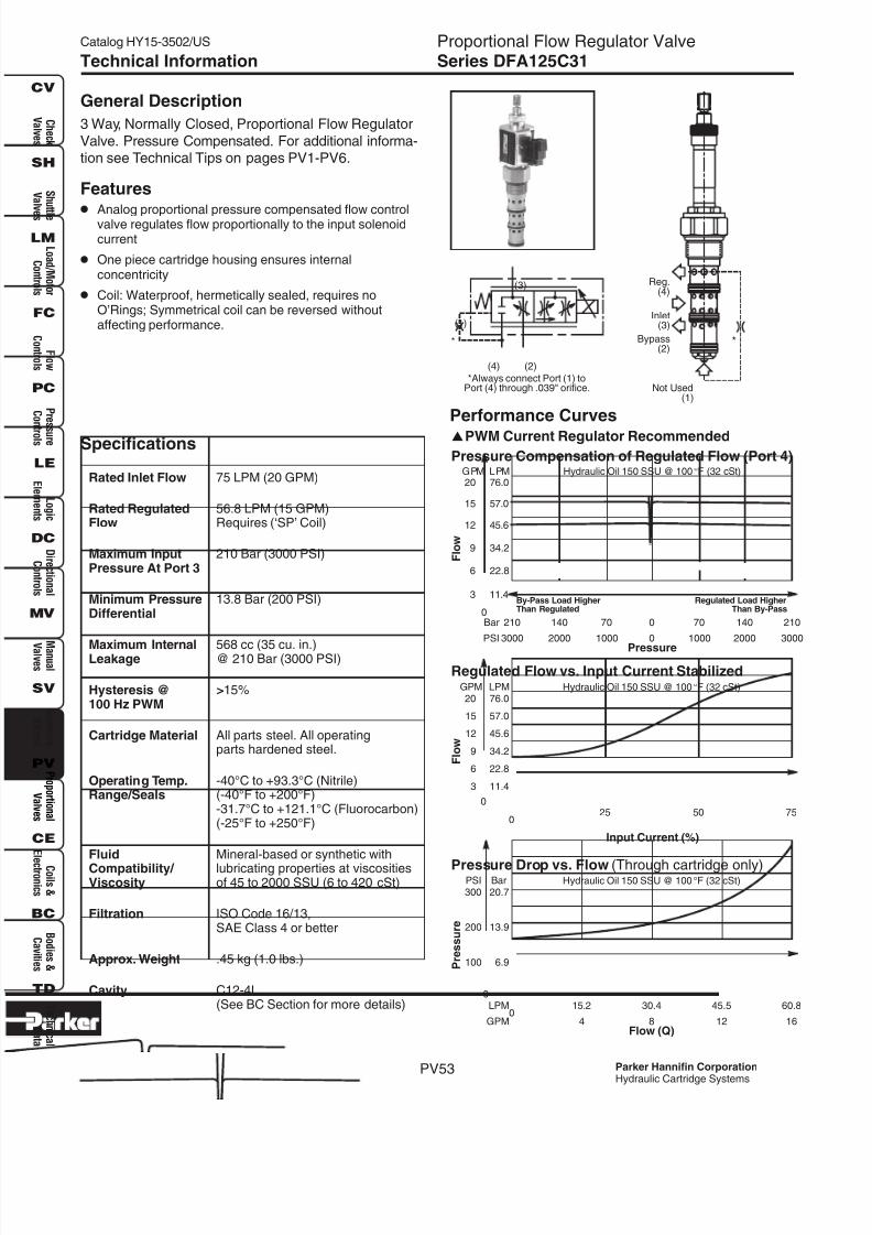
8/16/2019 Parker Catálogo de Válvulas Proporcionales
http://slidepdf.com/reader/full/parker-catalogo-de-valvulas-proporcionales 54/62
Catalog HY15-3502/US
Parker Hannifin Corporation
Hydraulic Cartridge Systems
C h e c k
V a l v e s
S h u t t l e
V a l v
e s
L o a d / M o t o r
C o n t r o l s
F l o w
C o n t r o l s
P r e s
s u r e
C o n
t r o l s
L o g i c
E l e me n t s
D i r e c t i o n a l
C o n t r o l s
M a n u a l
V a l v e s
S o l e n o i d
V a l v e s
P r o p o r t i o n a l
V a l v e s
C o i l s &
E l e c t r o n i c s
B o d i e s &
C a v i t i e s
T e c h n i c a l
D a t a
SH
CV
LM
FC
PC
LE
DC
MV
SV
PV
CE
BC
TD
PV53
Proportional Flow Regulator ValveSeries DFA125C31Technical Information
Specifications
Rated Inlet Flow 75 LPM (20 GPM)
Rated Regulated 56.8 LPM (15 GPM)Flow Requires (‘SP’ Coil)
Maximum Input 210 Bar (3000 PSI)Pressure At Port 3
Minimum Pressure 13.8 Bar (200 PSI)Differential
Maximum Internal 568 cc (35 cu. in.)Leakage @ 210 Bar (3000 PSI)
Hysteresis @ >15%100 Hz PWM
Cartridge Material All parts steel. All operatingparts hardened steel.
Operating Temp. -40°C to +93.3°C (Nitrile)Range/Seals (-40°F to +200°F)
-31.7°C to +121.1°C (Fluorocarbon)(-25°F to +250°F)
Fluid Mineral-based or synthetic with
Compatibility/ lubricating properties at viscositiesViscosity of 45 to 2000 SSU (6 to 420 cSt)
Filtration ISO Code 16/13,SAE Class 4 or better
Approx. Weight .45 kg (1.0 lbs.)
Cavity C12-4L(See BC Section for more details)
General Description
3 Way, Normally Closed, Proportional Flow Regulator
Valve. Pressure Compensated. For additional informa-tion see Technical Tips on pages PV1-PV6.
Features
• Analog proportional pressure compensated flow controlvalve regulates flow proportionally to the input solenoidcurrent
• One piece cartridge housing ensures internalconcentricity
• Coil: Waterproof, hermetically sealed, requires noO’Rings; Symmetrical coil can be reversed withoutaffecting performance.
Performance Curves
PWM Current Regulator Recommended
(4) (2)
(3)
(1)
*
*Always connect Port (1) toPort (4) through .039" orifice. Not Used
(1)
Bypass(2)
Inlet(3)
Reg.(4)
*
Input Current (%)
25 500
75
Hydraulic Oil 150 SSU @ 100°F (32 cSt)
0
3
6
34.2
45.6
57.0
76.0
11.4
22.8
9
12
15
20GPM LPM
F l o w
Regulated Flow vs. Input Current Stabilized
Hydraulic Oil 150 SSU @ 100°F (32 cSt)
0
100
13.9
20.7
6.9
200
300PSI Bar
P r e s s u r e
Pressure Drop vs. Flow (Through cartridge only)
Flow (Q)
30.4
8
15.2
4
LPM
GPM0
45.5
12
60.8
16
Pressure
140
2000
140
2000
210
3000
Bar
PSI
70
1000
0
0
70
1000
210
3000
Hydraulic Oil 150 SSU @ 100°F (32 cSt)
0
12
15
3
6
9
45.6
57.0
11.4
22.8
34.2
20 76.0GPM LPM
F l o w
Pressure Compensation of Regulated Flow (Port 4)
Regulated Load HigherThan By-Pass
By-Pass Load HigherThan Regulated
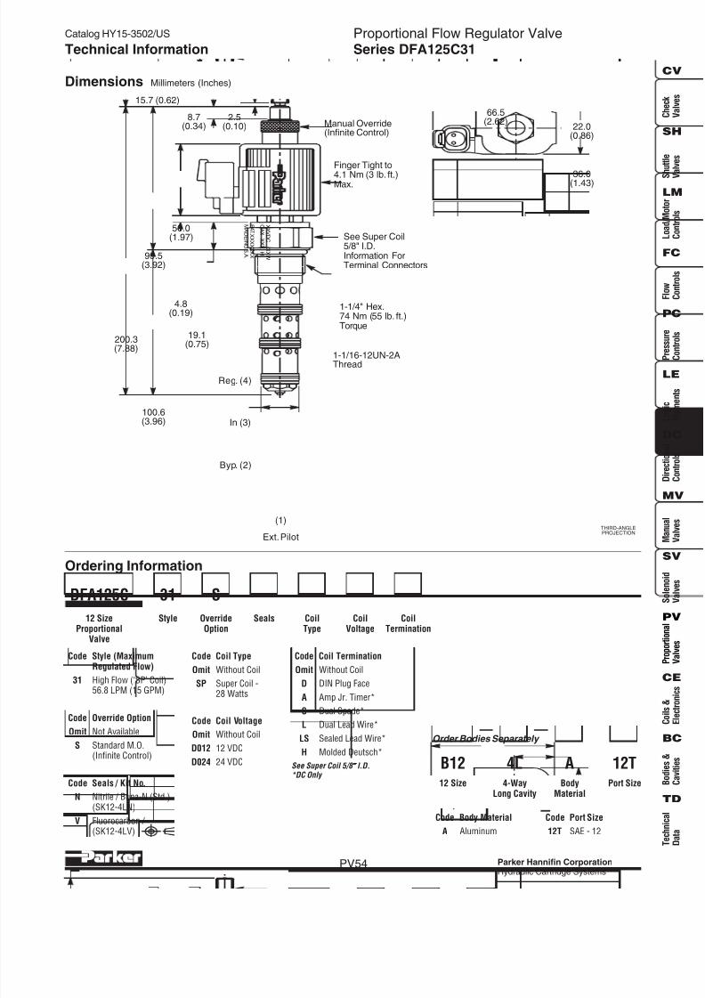
8/16/2019 Parker Catálogo de Válvulas Proporcionales
http://slidepdf.com/reader/full/parker-catalogo-de-valvulas-proporcionales 55/62
Catalog HY15-3502/US
Parker Hannifin Corporation
Hydraulic Cartridge Systems
Proportional Flow Regulator ValveSeries DFA125C31
PV54
Technical Information
OverrideOption
CoilType
CoilTermination
CoilVoltage
DFA125C
12 SizeProportional
Valve
Style
Code Override Option
Omit Not Available
S Standard M.O.(Infinite Control)
Dimensions Millimeters (Inches)
Ordering Information
THIRD-ANGLEPROJECTION
Code Style (MaximumRegulated Flow)
31 High Flow (‘SP’ Coil)56.8 LPM (15 GPM)
Code Port Size
12T SAE - 12
BodyMaterial
4-WayLong Cavity
Code Body Material
A Aluminum
12 Size
B12
Order Bodies Separately
Code Seals / Kit No.
N Nitrile / Buna-N (Std.)(SK12-4LN)
V Fluorocarbon / (SK12-4LV)
Seals
31
Code Coil Type
Omit Without Coil
SP Super Coil -28 Watts
Code Coil Voltage
Omit Without Coil
D012 12 VDC
D024 24 VDC
Code Coil Termination
Omit Without Coil
D DIN Plug Face
A Amp Jr. Timer*S Dual Spade*
L Dual Lead Wire*
LS Sealed Lead Wire*
H Molded Deutsch*
See Super Coil 5/8 ″ ″ ″ ″ ″ I.D.*DC Only
Port Size
4L A 12T
S
66.5(2.62)
22.0(0.86)
36.0(1.43)
XXVDC
XXW
CAX
XXX
H
PAT.XXXXXXX
MADEINU.S.A.
(1)Ext.Pilot
Reg. (4)
In (3)
Byp. (2)
1-1/16-12UN-2AThread
Manual Override(Infinite Control)
15.7 (0.62)
8.7(0.34)
2.5(0.10)
50.0(1.97)
200.3
(7.88)
100.6(3.96)
99.5(3.92)
4.8(0.19)
19.1(0.75)
Finger Tight to
4.1 Nm (3 lb. ft.)Max.
1-1/4" Hex.74 Nm (55 lb. ft.)Torque
See Super Coil5/8" I.D.Information ForTerminal Connectors

8/16/2019 Parker Catálogo de Válvulas Proporcionales
http://slidepdf.com/reader/full/parker-catalogo-de-valvulas-proporcionales 56/62
Catalog HY15-3502/US
Parker Hannifin Corporation
Hydraulic Cartridge Systems
C h e c k
V a l v e s
S h u t t l e
V a l v
e s
L o a d / M o t o r
C o n t r o l s
F l o w
C o n t r o l s
P r e s
s u r e
C o n
t r o l s
L o g i c
E l e me n t s
D i r e c t i o n a l
C o n t r o l s
M a n u a l
V a l v e s
S o l e n o i d
V a l v e s
P r o p o r t i o n a l
V a l v e s
C o i l s &
E l e c t r o n i c s
B o d i e s &
C a v i t i e s
T e c h n i c a l
D a t a
SH
CV
LM
FC
PC
LE
DC
MV
SV
PV
CE
BC
TD
PV55
Proportional Directional Control ValveSeries GP02 51, 51L, 52Technical Information
Specifications
Operating Ports 2, 3 and 4Pressure 350 Bar (5000 PSI)
Port 1210 Bar (3000 PSI)
Hysteresis @ <6%100 Hz PWM
Cracking Flow 25% to 30% of Input Signal
Variation of Flow ±15% @ 75% of Nominal Currentand Constant ∆P Maintained byPressure Compensator
Port to Port 10 cu. in. @ 3000 PSILeakage
Step Response On 50 msTime at 75% of Off 40 msAmps
Cartridge Material All parts steel. All operatingparts hardened steel.
Operating Temp. -40°C to +93.3°C (Nitrile)
Range/Seals (-40°F to +200°F)-31.7°C to +121.1°C (Fluorocarbon)(-25°F to +250°F)
Fluid Mineral-based or synthetic withCompatibility/ lubricating properties at viscositiesViscosity of 45 to 2000 SSU (6 to 420 cSt)
Filtration ISO Code 16/13,SAE Class 4 or better
Approx. Weight .15 kg (.34 lbs.)
Cavity C08-4
General Description4 Way, 3 Position, Proportional Directional ControlValve. Closed Center Spool. For additional information
see Technical Tips on pages PV1-PV6.
Features• One piece cartridge housing ensures internal
concentricity• Coil: Waterproof, hermetically sealed, requires no
O’Rings; Symmetrical coil can be reversed withoutaffecting performance.
Performance CurvesPWM Current Regulator Recommended
Typical Performance
RATED FLOW AT 75%OF NOMINAL CURRENTLPM - (GPM)
‘b’SOLENOID
PULLP to B, A to T
‘a’SOLENOID
PUSHP to A, B to T
PUSH PULL
Compensator∆∆∆∆∆P
Bar (PSI)
SPOOLTYPE AND
FLOW
51LLow Flow
51Standard
52High Flow
SUPERCOIL TYPE
5.3 - (1.4) 5.3 - (1.4) SP SP 10 (150)
3.4 - (0.9) 3.4 - (0.9) SS SS 5 (75)
13.3 - (3.5) 17 - (4.5) SP SP 15 (220)
11.4 - (3.0) 15.2 - (4.0) SS SS 15 (220)
21 - (5.5) 17 - (4.5) SP SP 20 (290)
17.4 - (4.5) 13 - (3.5) SP SP 15 (220)
(3)
(2)
(4)
(1)
(1)
(2)
(3)
(4)
0
3
1
11.4
3.8
5 19.0GPM LPM
F l o w
0CurrentAmps
.15
.3025%
.30
.6050%
.30
.6050%
.45
.9075%
.45
.9075%
.601.20
100%
.601.20
100%
24V12V
.15
.3025%
51L With 5 Bar, 75 PSI Compensator51 With 15 Bar, 220 PSI Compensator and SS Coil
51L
51
51L
51
PULL 'b'PUSH 'a'
Hydraulic Oil 150 SSU @ 100°F (32 cSt)
Pressure
70
1000
Bar
PSI
140
2000
210
30000
280
4000
350
5000
0
F l o w
1
7.6
11.4
15.2
3.8
2
3
4GPM LPM Hydraulic Oil 150 SSU @ 100°F (32 cSt)
Flow vs. Load
P to A, B toT
P to B, A toT P to B,A to T
P to A, B toT
Pressure Not CompensatedCompensatedWith Hydrostat P = 250 psi
0
F l o w
2
15.2
22.8
7.6
4
6
GPM LPM
52 With 20 Bar, 290 PSI Compensator and SP Coil
0CurrentAmps
.20
.4025%
.20
.4025%
.40
.8050%
.40
.8050%
.601.2075%
.601.2075%
.801.60
100%
.801.60
100%
24V12V
52 52
PUSH 'a' PULL 'b'
Hydraulic Oil 150 SSU @ 100°F (32 cSt)

8/16/2019 Parker Catálogo de Válvulas Proporcionales
http://slidepdf.com/reader/full/parker-catalogo-de-valvulas-proporcionales 57/62
Catalog HY15-3502/US
Parker Hannifin Corporation
Hydraulic Cartridge Systems
Proportional Directional Control ValveSeries GP02 51, 51L, 52
PV56
Technical Information
SealsOverrideOption
CoilType
CoilTermination
CoilVoltage
GP0208 Size
ProportionalValve
Style
Code Override Option
Omit Not Required
1 Manual Override
2 Detented M.O.
Dimensions Millimeters (Inches)
Ordering Information
THIRD-ANGLEPROJECTION
Code Style - Closed Center(Flow Pressure andPerformance)
51 Standard
51L Low Flow
52 High Flow
Code Seals / Kit No.
N Nitrile / Buna-N (Std.)(SK30078N-1)
V Fluorocarbon / (SK30078V-1)
M.O. Option(Unlatch andPull or Push)
LatchingSleeve
27.0(1.08)
6.0(.25) Stroke
62.7(2.47)
19.8(0.78)
33.8(1.33)
12.7(0.50)
53.0(2.10)
(1)
(2)
(3)
(4)
39.6(1.56)
39.6(1.56)
94.0(3.71)
X X V D
C
X X W
C C X
X X X
H
MA DE I N U. S .A .
P A T .X
X X X X X X
b
a
3/4 Hex.4.1 Nm(3 lb. ft.)Torque
7/8 Hex.30 Nm (22 lb. ft.)Torque
See Super Coil1/2" I.D.Information ForTerminal Connectors
SampleApplication Circuit(Closed Center)
3(P)
2(A)
1(T)
4(B)
13
2
3
2
1
Compensator(R04H3)
PortSize
BodyMaterial
* Add “A” for aluminum, omit for steel.
Code Port Size Body Part No.
Omit Cartridge Only
4T SAE-4 (B08-4-*4T)6T SAE-6 (B08-4-*6T)
6B 3/8″ BSPG (B08-4-*6B)
Code Body Material
Omit Steel
A Aluminum
Code Coil Voltage
Omit Without Coil
D012 12 VDC
D024 24 VDC
Code Coil Type
Omit Without Coil
SS Super Coil - 14 Watts
SP Super Coil - 19 Watts
Code Coil Termination
Omit Without Coil
D DIN Plug Face
A Amp Jr. Timer*
L Dual Lead Wire*LS Sealed Lead Wire*
H Molded Deutsch*
See Super Coil 1/2 ″ ″ ″ ″ ″ I.D.*DC Only

8/16/2019 Parker Catálogo de Válvulas Proporcionales
http://slidepdf.com/reader/full/parker-catalogo-de-valvulas-proporcionales 58/62
Catalog HY15-3502/US
Parker Hannifin Corporation
Hydraulic Cartridge Systems
C h e c k
V a l v e s
S h u t t l e
V a l v
e s
L o a d / M o t o r
C o n t r o l s
F l o w
C o n t r o l s
P r e s
s u r e
C o n
t r o l s
L o g i c
E l e me n t s
D i r e c t i o n a l
C o n t r o l s
M a n u a l
V a l v e s
S o l e n o i d
V a l v e s
P r o p o r t i o n a l
V a l v e s
C o i l s &
E l e c t r o n i c s
B o d i e s &
C a v i t i e s
T e c h n i c a l
D a t a
SH
CV
LM
FC
PC
LE
DC
MV
SV
PV
CE
BC
TD
PV57
Proportional Directional Control ValveSeries GP02 53, 53L, 54Technical Information
Specifications
Operating Ports 2, 3 and 4Pressure 350 Bar (5000 PSI)
Port 1210 Bar (3000 PSI)
Hysteresis @ <6%100 Hz PWM
Cracking Flow 25% to 30% of Input Signal
Variation of Flow ±15% @ 75% of Nominal Currentand Constant ∆P Maintained byPressure Compensator
Port to Port 10 cu. in. @ 3000 PSILeakage
Step Response On 50 msTime at 75% of Off 40 msAmps
Cartridge Material All parts steel. All operatingparts hardened steel.
Operating Temp. -40°C to +93.3°C (Nitrile)
Range/Seals (-40°F to +200°F)-31.7°C to +121.1°C (Fluorocarbon)(-25°F to +250°F)
Fluid Mineral-based or synthetic withCompatibility/ lubricating properties at viscositiesViscosity of 45 to 2000 SSU (6 to 420 cSt)
Filtration ISO Code 16/13,SAE Class 4 or better
Approx. Weight .15 kg (.34 lbs.)
Cavity C08-4
General Description4 Way, 3 Position, Proportional Directional ControlValve. Floating Center Spool. For additional information
see Technical Tips on pages PV1-PV6.
Features• One piece cartridge housing ensures internal
concentricity• Coil: Waterproof, hermetically sealed, requires no
O’Rings; Symmetrical coil can be reversed withoutaffecting performance.
Performance Curves
PWM Current Regulator Recommended
Typical Performance
RATED FLOW AT 75%OF NOMINAL CURRENTLPM - (GPM)
‘b’SOLENOID
PULLP to B, A to T
‘a’SOLENOID
PUSHP to A, B to T
PUSH PULL
Compensator∆∆∆∆∆P
Bar (PSI)
SPOOLTYPE AND
FLOW
53LLow Flow
53Standard
54High Flow
SUPERCOIL TYPE
5.3 - (1.4) 5 - (1.4) SP SP 10 (150)
4 - (1.0) 4 - (1.0) SS SS 5 (75)
14 - (3.8) 15 - (4.0) SP SP 10 (150)
9 - (2.5) 10 - (2.7) SS SS 5 (75)
17 - (4.5) 19 - (5.0) SP SP 20 (290)
15 - (4.0) 15 - (4.0) SS SS 15 (220)
(3)
(2)
(4)
(1)
(1)
(2)
(3)
(4)
53L
53
53L
53
PULL 'b'PUSH 'a'
0
3
1
11.4
3.8
5 19.0GPM LPM
F l o w
0CurrentAmps
.15
.3025%
.30
.6050%
.30
.6050%
.45
.9075%
.45
.9075%
.601.20
100%
.601.20
100%
24V12V
.15
.3025%
53 and 53L With 5 Bar, 75 PSICompensator and SS Coil
Hydraulic Oil 150 SSU @ 100°F (32 cSt)
5454
PUSH 'a' PULL 'b'
0
F l o w
2
15.2
22.8
7.6
4
6
GPM LPM
54 With 20 Bar, 290 PSI Compensator and SP Coil
0CurrentAmps
.20
.4025%
.20
.4025%
.40
.8050%
.40
.8050%
.601.2075%
.601.2075%
.801.60
100%
.801.60
100%
24V12V
Hydraulic Oil 150 SSU @ 100°F (32 cSt)
Pressure
70
1000
Bar
PSI
140
2000
210
30000
280
4000
350
5000
0
F l o w
1
7.6
11.4
15.2
3.8
2
3
4GPM LPM Hydraulic Oil 150 SSU @ 100°F (32 cSt)
Flow vs. Load
P to A,B to T
P to B, A toT P to B, A toT
P to A, B toT
Pressure Not CompensatedCompensated With Hydrostat P = 250 psi

8/16/2019 Parker Catálogo de Válvulas Proporcionales
http://slidepdf.com/reader/full/parker-catalogo-de-valvulas-proporcionales 59/62
Catalog HY15-3502/US
Parker Hannifin Corporation
Hydraulic Cartridge Systems
Proportional Directional Control ValveSeries GP02 53, 53L, 54
PV58
Technical Information
SealsOverrideOption
CoilType
CoilTermination
CoilVoltage
GP0208 Size
ProportionalValve
Style
Code Override Option
Omit Not Required
1 Manual Override
2 Detented M.O.
Dimensions Millimeters (Inches)
Ordering Information
THIRD-ANGLEPROJECTION
Code Style - Floating Center(Flow Pressure andPerformance)
53 Standard
53L Low Flow
54 High Flow
Code Seals / Kit No.
N Nitrile / Buna-N (Std.)(SK30078N-1)
V Fluorocarbon / (SK30078V-1)
M.O. Option(Unlatch andPull or Push)
LatchingSleeve
27.0(1.08)
6.0(.25) Stroke
62.7(2.47)
19.8(0.78)
33.8(1.33)
12.7(0.50)
53.0(2.10)
(1)
(2)
(3)
(4)
39.6(1.56)
39.6(1.56)
94.0(3.71)
X X V D
C
X X W
C C X
X X X
H
MA DE I N U. S .A .
P A T .X
X X X X X X
b
a
3/4 Hex.4.1 Nm(3 lb. ft.)Torque
7/8 Hex.30 Nm (22 lb. ft.)Torque
See Super Coil1/2" I.D.Information ForTerminal Connectors
SampleApplication Circuit(Floating Center)
3(P)
2(A)
1(T)
4(B)
13
2
3
2
1
Compensator(R04H3)
PortSize
BodyMaterial
* Add “A” for aluminum, omit for steel.
Code Port Size Body Part No.
Omit Cartridge Only
4T SAE-4 (B08-4-*4T)6T SAE-6 (B08-4-*6T)
6B 3/8″ BSPG (B08-4-*6B)
Code Body Material
Omit Steel
A Aluminum
Code Coil Voltage
Omit Without Coil
D012 12 VDC
D024 24 VDC
Code Coil Type
Omit Without Coil
SS Super Coil - 14 Watts
SP Super Coil - 19 Watts
Code Coil Termination
Omit Without Coil
D DIN Plug Face
A Amp Jr. Timer*
L Dual Lead Wire*LS Sealed Lead Wire*
H Molded Deutsch*
See Super Coil 1/2 ″ ″ ″ ″ ″ I.D.*DC Only

8/16/2019 Parker Catálogo de Válvulas Proporcionales
http://slidepdf.com/reader/full/parker-catalogo-de-valvulas-proporcionales 60/62
Catalog HY15-3502/US
Parker Hannifin Corporation
Hydraulic Cartridge Systems
C h e c k
V a l v e s
S h u t t l e
V a l v
e s
L o a d / M o t o r
C o n t r o l s
F l o w
C o n t r o l s
P r e s
s u r e
C o n
t r o l s
L o g i c
E l e me n t s
D i r e c t i o n a l
C o n t r o l s
M a n u a l
V a l v e s
S o l e n o i d
V a l v e s
P r o p o r t i o n a l
V a l v e s
C o i l s &
E l e c t r o n i c s
B o d i e s &
C a v i t i e s
T e c h n i c a l
D a t a
SH
CV
LM
FC
PC
LE
DC
MV
SV
PV
CE
BC
TD
PV59
Proportional Directional Control ValveSeries DSP105C1, C4Technical Information
Specifications
Operating 210 Bar (3000 PSI)Pressure
Hysteresis @ <6%100 Hz PWM
Cracking Flow 25% to 30% of Input Signal
Variation of Flow ±15% @ 75% of Nominal Currentand Constant ∆P Maintained byPressure Compensator
Port to Port 10 cu. in. @ 3000 PSILeakage
Step Response On 50 msTime at 75% of Off 40 msAmps
Cartridge Material All parts steel. All operatingparts hardened steel.
Operating Temp. -45°C to +93.3°C (“D”-Ring)Range/Seals (-50°F to +200°F)
-31.7°C to +121.1°C (Fluorocarbon)(-25°F to +250°F)
Fluid Mineral-based or synthetic withCompatibility/ lubricating properties at viscositiesViscostiy of 45 to 2000 SSU (6 to 420 cSt)
Filtration ISO Code 16/13,SAE Class 4 or better
Approx. Weight .28 kg (.57 lbs.)
Cavity C10-4
General Description4 Way, 3 Position, Proportional Directional ControlValve. Closed Center or Floating Center Spool. For
additional information see Technical Tips on pagesPV1-PV6.
Features• One piece cartridge housing ensures internal
concentricity
• Coil: Waterproof, hermetically sealed, requires noO’Rings; Symmetrical coil can be reversed withoutaffecting performance.
• All external parts zinc plated
Sample Application Circuit
3(P)
2(A)
1(T)
4(B)
13
2
3
2
1
Compensator(R04H3-15.0)
100 PSI CheckValveis recommended inTank Line
100 PSI CheckValveis recommended inTank Line
3(P)
2(A)
1(T)
4(B)
13
2
3
2
1
Compensator(R04H3-15.0)
(1)
(2)
(3)
(4)
CLOSED CENTER
FLOATING CENTER
(1)
(2)
(3)
(4)
(1)
(3)
(2)
(4)
Closed Center
Floating Center
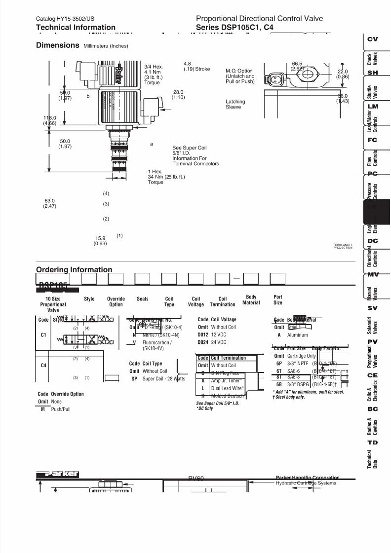
8/16/2019 Parker Catálogo de Válvulas Proporcionales
http://slidepdf.com/reader/full/parker-catalogo-de-valvulas-proporcionales 61/62
Catalog HY15-3502/US
Parker Hannifin Corporation
Hydraulic Cartridge Systems
Proportional Directional Control ValveSeries DSP105C1, C4
PV60
Technical Information
SealsOverrideOption
CoilType
CoilTermination
CoilVoltage
DSP10510 Size
ProportionalValve
Style
Code Override Option
Omit None
M Push/Pull
Dimensions Millimeters (Inches)
Ordering Information
THIRD-ANGLEPROJECTION
Code Style
C1
C4
Code Seals / Kit No.
Omit “D”-Ring / (SK10-4)
N Nitrile / (SK10-4N)
V Fluorocarbon / (SK10-4V)
M.O. Option(Unlatch andPull or Push)
LatchingSleeve
28.0
(1.10)
4.8(.19) Stroke
36.0(1.43)
22.0(0.86)
66.5(2.62)
50.0(1.97)
50.0(1.97)
15.9(0.63)
63.0(2.47)
(1)
(2)
(3)
(4)
118.0(4.66)
b
a
X X
V D C
X X W
C A
X X X X
H
P A T .X X X X X X X
MA
DE I N U. S .A .
3/4 Hex.4.1 Nm(3 lb. ft.)Torque
1 Hex.34 Nm (25 lb. ft.)Torque
See Super Coil5/8" I.D.Information ForTerminal Connectors
PortSize
BodyMaterial
* Add “A” for aluminum, omit for steel.† Steel body only.
Code Port Size Body Part No.
Omit Cartridge Only
6P 3/8″ NPTF (B10-4-*6P)
6T SAE-6 (B10-4-*6T)8T SAE-8 (B10-4-*8T)
6B 3/8″ BSPG (B10-4-6B)†
Code Body Material
Omit Steel
A Aluminum
Code Coil Voltage
Omit Without Coil
D012 12 VDC
D024 24 VDC
Code Coil Type
Omit Without Coil
SP Super Coil - 28 Watts
Code Coil Termination
Omit Without Coil
D DIN Plug Face
A Amp Jr. Timer*
L Dual Lead Wire*H Molded Deutsch*
See Super Coil 5/8 ″ ″ ″ ″ ″ I.D.*DC Only
(2)
(3)
(4)
(1)
(2)
(3)
(4)
(1)

8/16/2019 Parker Catálogo de Válvulas Proporcionales
http://slidepdf.com/reader/full/parker-catalogo-de-valvulas-proporcionales 62/62
Catalog HY15-3502/US
C h e c k
V a l v e s
S h u t t l e
V a l v
e s
L o a d / M o t o r
C o n t r o l s
F l o w
C o n t r o l s
P r e s
s u r e
C o n
t r o l s
L o g i c
E l e me n t s
D i r e c t i o n a l
C o n t r o l s
M a n u a l
V a l v e s
S o l e n o i d
V a l v e s
P r o p o r t i o n a l
V a l v e s
C o i l s &
E l e c t r o n i c s
SH
CV
LM
FC
PC
LE
DC
MV
SV
PV
CE
BC
Proportional Directional Control ValveSeries DSP105C1, C4
PWM Current Regulator Recommended
Performance Curves
Pressure Compensation Push CoilInlet toWork Port
0
2
4
6
8
7.6
15.2
22.8
30.4GPM LPM
Flow
Hydraulic Oil 150 SSU @ 100°F (32 cSt)
Pressure (PSI)
138
2000
172
2500
69
1000
34
500
103
1500
Bar
PSI0
207
3000
53 With 15 Bar, 220 PSI Compensator and SP Coil
0
2
4
6
8
7.6
15.2
22.8
30.4GPM LPM
Flow
Hydraulic Oil 150 SSU @ 100°F (32 cSt)
Current (Amps)
0.5 1.0-0.5-1.0-1.5 0 1.5
DSP105C4
51 With 15 Bar, 220 PSI Compensator and SP Coil
0
2
4
6
8
7.6
15.2
22.8
30.4GPM LPM
Flow
Hydraulic Oil 150 SSU @ 100°F (32 cSt)
Current (Amps)
0.6 1.2-0.6-1.2-1.8 0 1.8
DSP105C1
ssureDrop(P)
300 21
14
17
10
200
250
PSI Bar
150
51 Spool Port 3 to 4
Hydraulic Oil 150 SSU @ 100°F (32 cSt)
PullPush
Pressure Compensation Pull CoilInlet toWork Port
0
2
4
6
8
7.6
15.2
22.8
30.4
10 38.0GPM LPM
Flow
Hydraulic Oil 150 SSU @ 100°F (32 cSt)
Pressure (PSI)
138
2000
172
2500
69
1000
34
500
103
1500
Bar
PSI0
207
3000