Mnual Compressor Parafuso 06NA
33
GTS104 Compressor Application Guide
-
Upload
deco-dluxe -
Category
Documents
-
view
381 -
download
50
description
Manual do compressor Parafuso 06NA
Transcript of Mnual Compressor Parafuso 06NA

GTS104 Compressor Application Guide

ii
Table of Contents
1. Introduction ...................................................................................................................11.1 Scope ......................................................................................................................11.2 Compressor Offerings.............................................................................................11.3 Standard Features....................................................................................................1
1.3.1 Discharge Check Valve....................................................................................11.3.2 Discharge Muffler ............................................................................................11.3.3 Pressure Relief Valve.......................................................................................11.3.4 Oil Filter...........................................................................................................11.3.5 Oil Supply Solenoid Valve ..............................................................................11.3.6 Suction & Economizer Screens .......................................................................11.3.7 Unloading System............................................................................................11.3.8 Reversible Terminal Box .................................................................................2
1.4 Model Number Significance Chart .........................................................................22. Refrigerants and Lubricants ..........................................................................................3
2.1. Approved Refrigerants............................................................................................32.2. Approved Lubricants ..............................................................................................3
3. Environmental and Installation Considerations ............................................................33.1 Operating Ambient .................................................................................................33.2. Salt-Spray Requirements ........................................................................................3
4. Operating Limits & Controls.........................................................................................44.1 Operating Envelope ................................................................................................44.2 Temperature Limits ................................................................................................54.3 Unloader Operation ................................................................................................54.4 Oil Supply Control..................................................................................................6
4.4.1 Oil Pressure Requirements...............................................................................74.4.2 Pre-Lube Pump & Oil Solenoid Valve Control ...............................................8
4.5 Compressor Rotation Control.................................................................................95. Recommended Control Strategies ...............................................................................10
5.1 Head Pressure Control ..........................................................................................105.2 Suction Pressure Control ......................................................................................105.3 Economizer Pressure / Flow Control....................................................................105.4 Discharge Gas Temperature Control ....................................................................105.5 Suction Gas Temperature Control ........................................................................115.6 Economizer Return Gas Control...........................................................................115.7 Oil Temperature Control ......................................................................................11
5.7.1 On-cycle Control............................................................................................115.7.2 Off-cycle Control ...........................................................................................11
5.8 Motor Winding Temperature Control...................................................................116. Vortex Oil Separators..................................................................................................13

iii
6.1 Discharge Line Sizing...........................................................................................136.2 System Oil Charge................................................................................................136.3 External Oil Sump ................................................................................................136.4 Vortex Oil Separator Hardware ............................................................................13
7. Compressor Accessories .............................................................................................147.1 Oil Level Switch ...................................................................................................147.2 Oil Sump Heater ...................................................................................................147.3 Oil Cooler .............................................................................................................147.4 Integral Oil Filter ..................................................................................................14
7.4.1 Filter Change-Out Schedule...........................................................................147.4.2 Filter Change-Out Procedure .........................................................................15
7.5 Flanges, O-Rings, & Inlet Screens........................................................................157.6 Solenoid Coils ......................................................................................................157.7 Mating Electrical Connections .............................................................................167.8 Oil Supply Solenoid Valve ...................................................................................167.9 Unloader Solenoid Valves ....................................................................................167.10 Compressor Protection Module ............................................................................167.11 External Muffler ...................................................................................................16
8. Code Agency Certification ..........................................................................................178.1 Electrical Connection Requirements ....................................................................17
8.1.1 Power Connections ........................................................................................178.1.2 Wye-Delta Starting ........................................................................................188.1.3 Terminal Box .................................................................................................18
8.2 Pressure Requirements .........................................................................................188.2.1 Hydrostatic Design Pressures.........................................................................188.2.2 Pressure Relief Valve.....................................................................................18
9. Packaging and Storage Requirements......................................................................199.1. Packaging..............................................................................................................199.2. Shipping................................................................................................................199.3. Storage ..................................................................................................................19
10. Compressor Electrical Data .....................................................................................2010.1 Allowable Voltage Ranges ...................................................................................2010.2 Electrical Data ......................................................................................................2010.3 Motor Winding Thermistor ..................................................................................28
11. Required Safety Protection ......................................................................................29
GTS104 Compressor Application Guide 1 Rev. 3.3
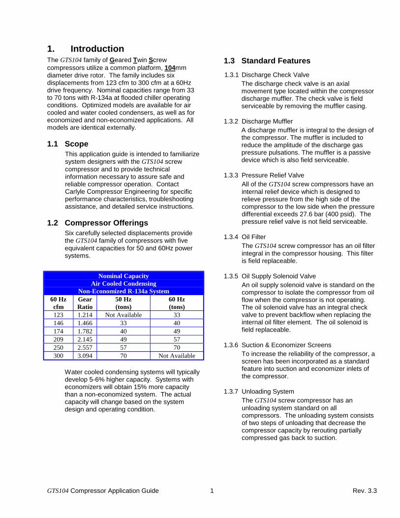
1. IntroductionThe GTS104 family of Geared Twin Screwcompressors utilize a common platform, 104mmdiameter drive rotor. The family includes sixdisplacements from 123 cfm to 300 cfm at a 60Hzdrive frequency. Nominal capacities range from 33to 70 tons with R-134a at flooded chiller operatingconditions. Optimized models are available for aircooled and water cooled condensers, as well as foreconomized and non-economized applications. Allmodels are identical externally.
1.1 ScopeThis application guide is intended to familiarizesystem designers with the GTS104 screwcompressor and to provide technicalinformation necessary to assure safe andreliable compressor operation. ContactCarlyle Compressor Engineering for specificperformance characteristics, troubleshootingassistance, and detailed service instructions.
1.2 Compressor OfferingsSix carefully selected displacements providethe GTS104 family of compressors with fiveequivalent capacities for 50 and 60Hz powersystems.
Nominal CapacityAir Cooled Condensing
Non-Economized R-134a System60 Hzcfm
GearRatio
50 Hz(tons)
60 Hz(tons)
123 1.214 Not Available 33146 1.466 33 40174 1.782 40 49209 2.145 49 57250 2.557 57 70300 3.094 70 Not Available
Water cooled condensing systems will typicallydevelop 5-6% higher capacity. Systems witheconomizers will obtain 15% more capacitythan a non-economized system. The actualcapacity will change based on the systemdesign and operating condition.
1.3 Standard Features
1.3.1 Discharge Check ValveThe discharge check valve is an axialmovement type located within the compressordischarge muffler. The check valve is fieldserviceable by removing the muffler casing.
1.3.2 Discharge MufflerA discharge muffler is integral to the design ofthe compressor. The muffler is included toreduce the amplitude of the discharge gaspressure pulsations. The muffler is a passivedevice which is also field serviceable.
1.3.3 Pressure Relief ValveAll of the GTS104 screw compressors have aninternal relief device which is designed torelieve pressure from the high side of thecompressor to the low side when the pressuredifferential exceeds 27.6 bar (400 psid). Thepressure relief valve is not field serviceable.
1.3.4 Oil FilterThe GTS104 screw compressor has an oil filterintegral in the compressor housing. This filteris field replaceable.
1.3.5 Oil Supply Solenoid ValveAn oil supply solenoid valve is standard on thecompressor to isolate the compressor from oilflow when the compressor is not operating.The oil solenoid valve has an integral checkvalve to prevent backflow when replacing theinternal oil filter element. The oil solenoid isfield replaceable.
1.3.6 Suction & Economizer ScreensTo increase the reliability of the compressor, ascreen has been incorporated as a standardfeature into suction and economizer inlets ofthe compressor.
1.3.7 Unloading SystemThe GTS104 screw compressor has anunloading system standard on allcompressors. The unloading system consistsof two steps of unloading that decrease thecompressor capacity by rerouting partiallycompressed gas back to suction.

GTS104 Compressor Application Guide 2 Rev. 3.3
1.3.8 Reversible Terminal BoxThe terminal box on the GTS104 compressor is180° reversible. This allows the power wiringto enter the box from either over the gearcover or over the motor casing. Thecompressor certified drawings show thestandard orientation of the box.
1.4 Model Number Significance Chart
Digit 1 2 3 4 5 6 7 8 9 10 11 12
| | | | | | | |0 6 N A 1 1 2 3 S 6 E A
Model Designation Number Packaging06N - GTS104 Compressor A - Standard Packaging
B - Service PackagingApplicationA - Air Cooled CondensingW - Water Cooled Condensing Motor Cooling
E - EconomizedN - Non-Economized
Digit #5 (Liquid Cooled)1 – No Significance2 – No Significance
Drive FrequencyNominal Displacement @ 60 Hz 5 - 50 Hz Only123 - 123 cfm 6 - 60 Hz Only146 - 146 cfm 7 - 50/60 Hz174 - 174 cfm209 - 209 cfm Electrical Characteristics (V/φφφφ/Hz)250 - 250 cfm S - 460-3-60 400-3-50300 - 300 cfm T - 575-3-60 ---
U - --- 230-3-50W - 380-3-60 346-3-50X - 208/230-3-60 200-3-50Z - 200-3-60 ---
See Section 10.2 for valid model number configurations.

GTS104 Compressor Application Guide 3 Rev. 3.3
2. Refrigerants andLubricants
2.1. Approved RefrigerantsThe GTS104 screw compressor is specificallydesigned for use in R-134a systems only.
2.2. Approved LubricantsThe GTS104 screw compressor is approved foruse with the following lubricants:
Carrier Material Spec PP47-32
Approved Lubricant Castrol SW220
Viscosity Grade ISO 220
Carrier RCD Part #1 gallon P903-12015 gallon P903-1205
On occasion it may be necessary to use anassembly grease to retain an o-ring within itsgroove. The GTS104 screw compressor isapproved for use with the following assemblygrease:
Carrier Material Spec PP80-29
Approved Lubricant Castrol Synplex GP2
3. Environmental andInstallation Considerations
3.1 Operating AmbientThe screw compressor is designed to operate inthe following ambient temperature ranges:
Non-Operating -40°C(-40.0°F) to 82°C (180°F)
Operating -32°C(-25.6°F) to 55°C (131°F)
3.2. Salt-Spray RequirementsThe compressor and its accessories have beentested through 500 hours of salt-spray incompliance with ASTM specification B-117,(Carrier Engineering Requirement R-203).

GTS104 Compressor Application Guide 4 Rev. 3.3
4. Operating Limits & Controls
4.1 Operating EnvelopeThe following R-134a operating envelopes,Figures 4.1-1 and 4.1-2, show where thecompressor can be operated in both direct
expansion and flooded applications. Theenvelopes differ for the unique designconfiguration of the compressor. The fourth digitof the model number dictates the operatingenvelope.
Pressure limits are described in Section 8.
Figure 4.1-1 06NA CompressorAir-Cooled Condensing Operating Envelope
Figure 4.1-2 06NW CompressorWater-Cooled Condensing Operating Envelope
75
75
65
65
55
55
45
45
35
35
25
25
15
15
-30
-30
-20
-20
-10
-10
0
0
10
10
20
20
Saturated Suction Temperature (deg C)
Saturated Suction Temperature (deg C)
DischargeTemperatureLimit for 1/3Load State
DischargeTemperatureLimit for 1/3Load State
DischargeTemperatureLimit for 2/3Load State
DischargeTemperatureLimit for FullLoad State
DischargeTemperatureLimit for 1/3Load State
DischargeTemperatureLimit for FullLoad State

GTS104 Compressor Application Guide 5 Rev. 3.3
4.2 Temperature LimitsThe following table is intended to show the rangeof control points allowable for the compressoroperating on R-134a and Castrol SW-220 oil.
Section 5 lists different methods to control theoperating pressures and temperatures, andSection 11 provides a complete list of therequired safety protection.
4.3 Unloader OperationAll GTS104 compressors come equipped withunloaders for three stages of operation -nominally 1/3, 2/3 and full load. The actualcapacity reduction will depend on the systemoperating condition and rebalancecharacteristics.
Two solenoid actuated poppet-style unloadersaccomplish unloading. These poppet valveseither block or allow communication of a portionof the compression chamber with the suctionplenum. The poppets are situated to permit gasto escape from the compression chamber just asit begins to decrease in volume and thusminimize any compression work being done onthe gas.
The power head of the unloader pistons is atsuction pressure in the de-energized, unloaded,state. Discharge pressure is applied to thepower head to close the poppet valve when thesolenoid is energized.
The compressor will start with minimum powerdraw in the fully unloaded (1/3 load) state - bothsolenoids de-energized. There is no minimumor maximum time limit immediately after startupfor which the compressor must operate in theunloaded state. However, it is recommendedthat the compressor be operated at 1/3 load for30 seconds just prior to shutdown. This will
ensure the compressor is fully unloaded on thesubsequent start.
If additional capacity is required, one or both ofthe unloader solenoids can be energized. Thecompressor is fully loaded when both solenoidsare in the energized state. It is more efficient toobtain the 2/3 capacity step by having the highstage solenoid (the one located closer to thedischarge end of the compressor) energized,and the low stage solenoid de-energized. If thecontrol solenoids are reversed, the compressorwill operate at approximately 1/2 full capacity butnearly full power.
Table 4.3-1 shows the proper control states forthe unloader system.
Table 4.3-1Unloader System Control States
Full Load 2/3 Step 1/3 Step ***
TypicalCapacity 100% 70% 45%
TypicalPower 100% 85% 65%
HighStage
SolenoidEnergized Energized De-Energized
LowStage
SolenoidEnergized De-Energized De-Energized
*** This is the required start-up position ofthe unloaders.
Note: The solenoid coils used to control theunloaders are specified in Section 7.
For a given operating condition, compressordischarge temperatures will be higher with thecompressor running in an unloaded state than itwould be for the fully loaded state. The operatinglimits described for full load operation must alsobe considered when operating in an unloadedstate. The compressor can operate in theunloaded state over the entire operatingenvelope. Standard troubleshooting proceduresshould be followed in the event that a protectivelimit is exceeded.
Minimum Maximum
Discharge Gas11°C (20°F)superheat 99°C (210°F)
Economizer GasSaturated Liquid 5°C (10°F)
superheat
Suction GasSaturated
VaporSee Section 5.5
Oil Supply atCompressor
SeeSection 5.7 99°C (210°F)
Motor WindingsNominal Running No limit 93°C (200°F)Must Not Exceed No limit 118°C (244°F)
GTS104 Compressor Application Guide 6 Rev. 3.3
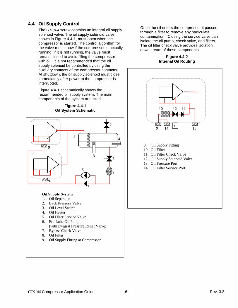
4.4 Oil Supply ControlThe GTS104 screw contains an integral oil supplysolenoid valve. The oil supply solenoid valve,shown in Figure 4.4-1, must open when thecompressor is started. The control algorithm forthe valve must know if the compressor is actuallyrunning. If it is not running, the valve mustremain closed to avoid filling the compressorwith oil. It is not recommended that the oilsupply solenoid be controlled by using theauxiliary contacts of the compressor contactor.At shutdown, the oil supply solenoid must closeimmediately after power to the compressor isinterrupted.
Figure 4.4-1 schematically shows therecommended oil supply system. The maincomponents of the system are listed.
Figure 4.4-1Oil System Schematic
Oil Supply System1. Oil Separator2. Back Pressure Valve3. Oil Level Switch4. Oil Heater5. Oil Filter Service Valve6. Pre-Lube Oil Pump
(with Integral Pressure Relief Valve)7. Bypass Check Valve8. Oil Filter9. Oil Supply Fitting at Compressor
Once the oil enters the compressor it passesthrough a filter to remove any particulatecontamination. Closing the service valve canisolate the oil pump, check valve, and filters.The oil filter check valve provides isolationdownstream of these components.
Figure 4.4-2Internal Oil Routing
9 Oil Supply Fitting10. Oil Filter11. Oil Filter Check Valve12. Oil Supply Solenoid Valve13. Oil Pressure Port14. Oil Filter Service Port
9
9
1
6
7
8
5
4
3
2149
10 12 11
13s
GTS104 Compressor Application Guide 7 Rev. 3.3
4.4.1 Oil Pressure RequirementsThere are two minimum oil pressure criteria thatmust be met for the GTS104 compressor.
The first criteria is that the pressuredifferential between the oil galley pressureand the economizer pressure must satisfythe appropriate limit:
For 06NA compressors:
Poil Pecon− ≥
0.7bar
10psidfor all Ps
For 06NW compressors:
Poil Pecon− ≥
× +×
≤≤
≥≥
0.7bar
10psid
0.1613 Ps 0.300
0.1613 Ps + 4.355
1.0bar
15psid
for Ps 2.3 bar
for Ps 35 psia
for 2.3 < Ps < 4.5 bar
for 35 < Ps < 66 psia
for Ps 4.5 bar
for Ps 66 psia
At low pressure differential operatingconditions special system controls arerequired to maintain adequate oil supply tothe compressor. A backpressure valve isshown in Figure 4.4-1 for this purpose.
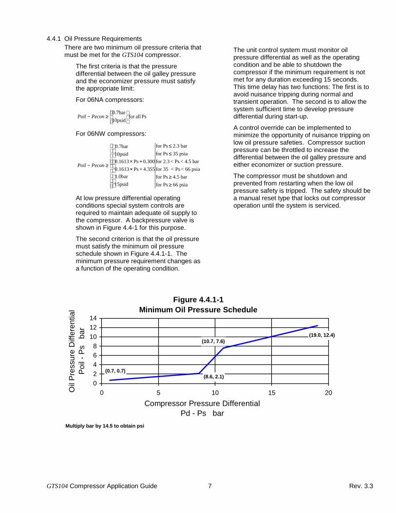
The second criterion is that the oil pressuremust satisfy the minimum oil pressureschedule shown in Figure 4.4.1-1. Theminimum pressure requirement changes asa function of the operating condition.
The unit control system must monitor oilpressure differential as well as the operatingcondition and be able to shutdown thecompressor if the minimum requirement is notmet for any duration exceeding 15 seconds.This time delay has two functions: The first is toavoid nuisance tripping during normal andtransient operation. The second is to allow thesystem sufficient time to develop pressuredifferential during start-up.
A control override can be implemented tominimize the opportunity of nuisance tripping onlow oil pressure safeties. Compressor suctionpressure can be throttled to increase thedifferential between the oil galley pressure andeither economizer or suction pressure.
The compressor must be shutdown andprevented from restarting when the low oilpressure safety is tripped. The safety should bea manual reset type that locks out compressoroperation until the system is serviced.
Figure 4.4.1-1Minimum Oil Pressure Schedule
(0.7, 0.7)(8.6, 2.1)
(10.7, 7.6)(19.0, 12.4)
02468
101214
0 5 10 15 20
Compressor Pressure DifferentialPd - Ps bar
Oil
Pre
ssur
eD
iffer
entia
lP
oil-
Ps
bar
Multiply bar by 14.5 to obtain psi

GTS104 Compressor Application Guide 8 Rev. 3.3
4.4.2 Pre-Lube Pump & Oil Solenoid Valve ControlA pre-lube oil pump is required in the oil circuit toprovide lubrication to the bearings prior to start-up ofthe compressor.
A pre-lube cycle must be initiated each time acompressor is started. Figure 4.4.2-1 shows therecommended pre-lube cycle control sequence to befollowed when starting a compressor.
Figure 4.4.2-1Pre-Lube Cycle Flowchart
Capaci tyContro l
Reques tsCompresso r
Start
Open Oi l Solenoid Valve
IsOi l Pressure >
P ref_1 + Target?
N o
Has 15 secondse lapsed?
N o Loop runsevery second
At tempt = 1?
Yes
Set At tempt = 2Set Target = 0.04 bar
Yes
N o
Set AlarmFlag
LockoutCompresso r
Wai t 5seconds
Star t Compressor
Wai t 15seconds
Turn Of f Pump
Successfu lStar tup
Comple te
Read Refe renceOi l Pressure, Pref_1
Set Attempt = 1Set Target = 0.10 bar
Turn on Oi l Pump,Wai t 20 seconds
(40 sec @ low ambient)
Read Second Refe rencePressure, Pref_2
IsPref_2 >
Pref_1 + 0.17 bar?
Yes
Wai t 5seconds
Oil Solenoid isFai led Open,
Abor t Pre-LubeCycle, Set Alarm
YesN o
Turn on Oi l Pump,Wai t 10 seconds
Turn Of f PumpClose Oi l Solenoid
Mult iply bar by14.5 to obtain psi

GTS104 Compressor Application Guide 9 Rev. 3.3
4.5 Compressor Rotation ControlCorrect compressor rotation is one of the mostcritical application considerations. Poweredreverse rotation, even for a very short duration,can seriously affect the reliability of thecompressor.
The reverse rotation protection scheme mustbe capable of determining the direction ofrotation and stopping the compressor within300 milliseconds.
Reverse rotation is most likely to occurwhenever the wiring to the compressor terminalsis disturbed.
To minimize the opportunity for reverse rotation,Carlyle recommends the following procedures:
1) During factory run test of the chiller, a low-pressure switch should be temporarilyinstalled as a hard safety on the high-pressure port of the compressor. Thepurpose of this switch is to protect thecompressor against any wiring errors at thecompressor terminal pins. The electricalcontacts of the switch should be wiredbetween the CPM and the compressor high-pressure switch. This switch should remainin place for the duration of the run test. Atthe end of the run test the switch should beremoved so that it could be used on the nextchiller/compressor to be tested.
2) For service replacement compressors, asimilar protection system is recommended.All service compressors should have a low-pressure switch included with thecompressor. The chiller service literatureshould make reference to this switch andprovide instructions on how to temporarilyinstall the low-pressure switch into the safetychain for the compressor. Each servicecompressor should be supplied withInstallation Instructions documenting theprocedure for installing and using the switch.The switch should remain in place until thecompressor has been started and directionof rotation has been verified, at this point theswitch should be removed and discarded.
The switch that has been selected for detectingreverse rotation is specified on CarrierPurchased Part Specification HK01CB001. Thisswitch opens the contacts when the pressurefalls below 50.8mm (2 inches) of vacuum. Theswitch is a manual reset type that can be resetafter the pressure has once again risen above1.7 bar (25 psia). It is critical that the switch be amanual reset type to preclude the compressorfrom short cycling in the reverse direction. Thisswitch is also used on the GTS74 screwcompressor to detect reverse rotation.
GTS104 Compressor Application Guide 10 Rev. 3.3
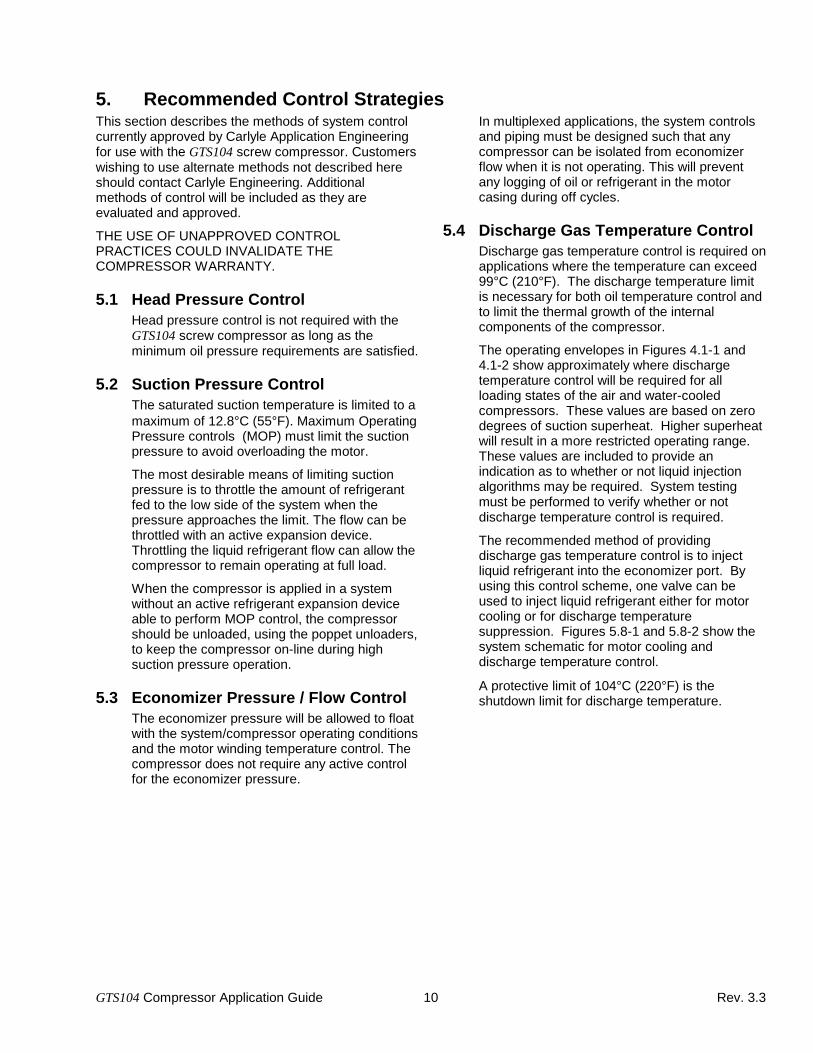
5. Recommended Control StrategiesThis section describes the methods of system controlcurrently approved by Carlyle Application Engineeringfor use with the GTS104 screw compressor. Customerswishing to use alternate methods not described hereshould contact Carlyle Engineering. Additionalmethods of control will be included as they areevaluated and approved.
THE USE OF UNAPPROVED CONTROLPRACTICES COULD INVALIDATE THECOMPRESSOR WARRANTY.
5.1 Head Pressure ControlHead pressure control is not required with theGTS104 screw compressor as long as theminimum oil pressure requirements are satisfied.
5.2 Suction Pressure ControlThe saturated suction temperature is limited to amaximum of 12.8°C (55°F). Maximum OperatingPressure controls (MOP) must limit the suctionpressure to avoid overloading the motor.
The most desirable means of limiting suctionpressure is to throttle the amount of refrigerantfed to the low side of the system when thepressure approaches the limit. The flow can bethrottled with an active expansion device.Throttling the liquid refrigerant flow can allow thecompressor to remain operating at full load.
When the compressor is applied in a systemwithout an active refrigerant expansion deviceable to perform MOP control, the compressorshould be unloaded, using the poppet unloaders,to keep the compressor on-line during highsuction pressure operation.
5.3 Economizer Pressure / Flow ControlThe economizer pressure will be allowed to floatwith the system/compressor operating conditionsand the motor winding temperature control. Thecompressor does not require any active controlfor the economizer pressure.
In multiplexed applications, the system controlsand piping must be designed such that anycompressor can be isolated from economizerflow when it is not operating. This will preventany logging of oil or refrigerant in the motorcasing during off cycles.
5.4 Discharge Gas Temperature ControlDischarge gas temperature control is required onapplications where the temperature can exceed99°C (210°F). The discharge temperature limitis necessary for both oil temperature control andto limit the thermal growth of the internalcomponents of the compressor.
The operating envelopes in Figures 4.1-1 and4.1-2 show approximately where dischargetemperature control will be required for allloading states of the air and water-cooledcompressors. These values are based on zerodegrees of suction superheat. Higher superheatwill result in a more restricted operating range.These values are included to provide anindication as to whether or not liquid injectionalgorithms may be required. System testingmust be performed to verify whether or notdischarge temperature control is required.
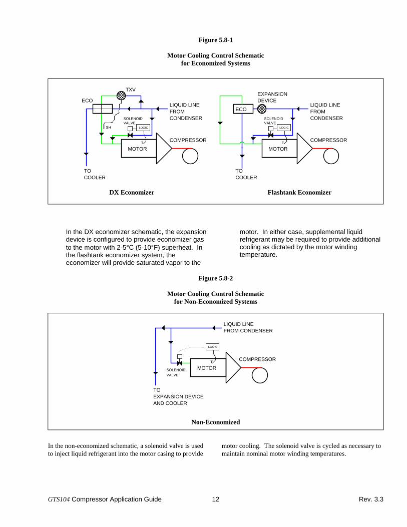
The recommended method of providingdischarge gas temperature control is to injectliquid refrigerant into the economizer port. Byusing this control scheme, one valve can beused to inject liquid refrigerant either for motorcooling or for discharge temperaturesuppression. Figures 5.8-1 and 5.8-2 show thesystem schematic for motor cooling anddischarge temperature control.
A protective limit of 104°C (220°F) is theshutdown limit for discharge temperature.

GTS104 Compressor Application Guide 11 Rev. 3.3
5.5 Suction Gas Temperature ControlControl of the return gas temperature for theGTS104 screw compressor is no different thanother compressors, screw or reciprocating. Theapplication of screw compressors is much moreforgiving in the area of liquid floodback to thecompressor.
As specified in the temperature limits in Section4.2, continuous floodback to the compressorshould be avoided since it can lead tomechanical damage. The return gastemperature can be allowed to float over a widerange as long as the discharge gas temperaturelimit is not exceeded.
The conventional means of suction gastemperature control, thermostatic and electronicexpansion devices for example, are approved byCarlyle Engineering as acceptable methods ofcontrol.
In flooded applications, liquid level in the coolerwill determine the return gas temperature. Floatactuated valves are acceptable means of coolerlevel control.
5.6 Economizer Return Gas ControlThe economizer gas is used to cool thecompressor motor. The temperature/quality ofthe economizer return gas must be controlled inorder to maintain the proper motor windingtemperature as described in Section 5.8.
5.7 Oil Temperature ControlOil temperature control is critical in order tomaintain adequate lubricant viscosity. The rollingelement bearings in the GTS104 screwcompressor require a minimum oil viscosity of6 cSt. An oil cooler is required on applicationswhere the oil viscosity falls below this limit.Section 7.3 describes the requirements for oilcoolers.
5.7.1 On-cycle ControlSystems that use the recommended oil andsatisfy the discharge gas temperature limits willnot require oil temperature control.
5.7.2 Off-cycle ControlDuring periods when the compressor is notrunning, system design precautions shouldpreclude the possibility of liquid refrigerantaccumulating in the oil separator. This can beaccomplished by heating the oil reservoir to driverefrigerant out of the oil, and by piping therefrigerant lines such that liquid cannot freelydrain from the condenser back to the oilseparator. In applications where refrigerant canfreely drain back to the oil reservoir, theminimum oil temperature should be maintained17°C (30°F) above ambient temperature.
5.8 Motor Winding Temperature ControlThe maximum continuous operating motorwinding temperature is 93°C (200°F).Economizer return gas with low superheat[approximately 5°C (10°F)] should providesufficient cooling for most compressors at mostoperating conditions. At more severe operatingconditions, the refrigerant entering the motor willhave to run "wet", either saturated or atwo-phase quality.
Figure 5.8-1 shows a refrigerant flow schematicfor a single compressor system with aneconomizer and supplemental liquid injection.Figure 5.8-2 shows the recommended motorcooling scheme for non-economized systems.
The unit control system should contain a controlalgorithm that monitors the motor windingtemperature, and modulates the liquid refrigerantflow as necessary to maintain acceptable motortemperatures.
The motor winding temperature is measured viaa thermistor embedded directly in the motorwindings. Section 10 provides details of thethermistor.
A protective limit of 118°C (245°F) is theshutdown limit for the motor windingtemperature.
GTS104 Compressor Application Guide 12 Rev. 3.3
Figure 5.8-1
Motor Cooling Control Schematicfor Economized Systems
COMPRESSOR
ECO
TXV
MOTORT
SOLENOIDVALVE
SH LOGIC
CONDENSERFROM
TOCOOLER
COMPRESSOR
ECO
MOTORT
SOLENOIDVALVE
LOGIC
CONDENSERFROM
TOCOOLER
EXPANSIONDEVICE
LIQUID LINE LIQUID LINE
DX Economizer Flashtank Economizer
In the DX economizer schematic, the expansiondevice is configured to provide economizer gasto the motor with 2-5°C (5-10°F) superheat. Inthe flashtank economizer system, theeconomizer will provide saturated vapor to the
motor. In either case, supplemental liquidrefrigerant may be required to provide additionalcooling as dictated by the motor windingtemperature.
Figure 5.8-2
Motor Cooling Control Schematicfor Non-Economized Systems
COMPRESSOR
MOTORT
SOLENOIDVALVE
LOGIC
FROM CONDENSERLIQUID LINE
TO
AND COOLEREXPANSION DEVICE
Non-Economized
In the non-economized schematic, a solenoid valve is usedto inject liquid refrigerant into the motor casing to provide
motor cooling. The solenoid valve is cycled as necessary tomaintain nominal motor winding temperatures.

GTS104 Compressor Application Guide Rev. 3.313
6. Vortex Oil Separators
6.1 Discharge Line SizingThe inlet piping to the 8" vortex separator shouldbe sized to maintain sufficient velocity atminimum load conditions of the circuit. The gasvelocity at minimum load should be maintainedat 6.1 meters per second (20 fps). With this linesize, a check should be made at the full loadcondition; velocities at full load should be limitedto 22.9 meters per second (75 fps) to avoidexcessive pressure drop across the separator. Ifthe application will operate outside of theselimits, consult Carlyle Application Engineering foradditional recommendations.
6.2 System Oil ChargeOil separator performance can be significantlyimpacted by system induced transients. Thereare several minor adjustments that can be madeto the oil system to make it more robust in termsof handling these transient conditions.
Provided that the separator is installed withproperly sized lines, the most likely causes ofpoor oil separation are excessive liquid carry-over through the discharge of the compressor orexcessive oil charge in the system. Eithertransient will manifest itself in a similar manner.
The oil separator contains a baffle plate thatdivides the separation chamber from the oilstorage sump area. If the oil in the sump arearises above the level of the baffle plate theseparator will no longer be able to separateeffectively because the separated oil hasnowhere to drain. Excessive liquid carry-overfrom the compressor(s) can cause this since theliquid refrigerant will also be separated anddrained into the sump area. It will be absorbedinto the oil causing the volume of oil to expand.Likewise, if the system is over charged with oil,the volume of oil alone can cause the level torise past the baffle plate.
It is recommended that all systems using thevortex style separators install an external oilsump in conjunction with the separator.
6.3 External Oil SumpApplying the external oil sump is rather simple atnormal design and operating conditions, butrequires some caution to avoid problems. Duringtransients, any outgassed refrigerant shouldfree-vent back to the separator.
The external sump, conceptually shown below,will provide over 14 gallons of oil storagecapacity. However, filling the reservoir to thislevel would leave any free surface for refrigerantto outgas from the oil. The sump should not befilled more than 50% which leaves room for theoil level to grow during outgassing transients.
The large connection between the separator andsump allow any outgassed refrigerant in thesump to be directly vented back to the oilseparator. Figure 6.3-1 shows theseparator/sump configuration.
Figure 6.3-1
Oil Separator & Sump Schematic
Inlet
Outlet
Oil Separator
External Oil Sump
Oil Supply Drain
6.4 Vortex Oil Separator HardwareThe oil separation hardware discussedthroughout this section is available as Carlylepart numbers KH 31YA 347 and KH 31MZ 150for the separator and sump, respectively.
GTS104 Compressor Application Guide Rev. 3.314
7. Compressor Accessories
7.1 Oil Level SwitchThe recommended oil level switch is a float styleswitch. This switch is normally open when no oillevel exists. An adequate oil level is required toraise the float along the stem and close thecontacts.
Additional details on this switch are available onthe Carrier purchased part specificationsHK13ZB001 and HK13ZB002.
Fluctuations in discharge pressure of themachine can cause outgassing of refrigerantwithin the oil sump that creates foam in the oilsump. Depending on the severity of thetransient, the foam can cause a nuisance trip onlow oil level. Control system design should takethis into consideration and delay compressorshutdown until the low oil level reading can beverified. The verification time should not exceedten seconds.
7.2 Oil Sump HeaterAn oil sump heater is recommended to preventoil dilution during times when the refrigerantcircuit is not in operation. The oil heater must besized to maintain the minimum oil temperature inthe lowest allowable starting ambient. However,the watt density of the heater must not be sohigh that the local oil heating around the elementraises the oil temperature above the specifiedmaximum. See Section 4 for temperature limits.
7.3 Oil CoolerAn oil cooler is required where the oil viscositywill be less than 6 centistokes. The oil coolershould be sized to provide sufficient heatrejection to meet this viscosity requirement.Compressor oil flow rates depend on theoperating condition, but can be estimated as0.25 liters/second (4.0 gpm) for the purpose ofsizing an oil cooler.
7.4 Integral Oil FilterThe integral oil filter in the GTS104 screwcompressors is specified to provide a high levelof filtration required for long bearing life. Systemcleanliness is critical to reliable systemoperation, however, the integral oil filter shouldnot be counted on as the device which cleansout manufacturing debris.
The replacement filter element part number is:
Carlyle part number: 8TB0320Parker part number: 932777Q
An alternate filter element is:
Carrier part number: KH 39MG 001Parker part number: 931984
Both elements provide similar filtration, rated asβ3 < 20. However, it may be more difficult toremove the KH 39MG 001 element from thecompressor since it does not have a removalring.
It is recommended to change the o-ring on thecover plug any time that the filter cavity isopened. The replacement part numbers for theo-ring are:
Carrier part number: 8TB0847
The oil filter will require replacement if itbecomes plugged with dirt and othercontaminants from the system. Including acoarser filter in the oil line upstream of theintegral filter can extend the service life of theintegral oil filter. This filter should be sizedbased on the individual system requirements.
7.4.1 Filter Change-Out ScheduleThe filter should be checked after the first1000 hours of operation, and every subsequent4000 hours. The filter should be replaced atany time when the pressure differentialacross the filter exceeds 2.1 bar, (30 psid).
The pressure drop across the filter can bedetermined by measuring the pressure at thefilter service port and the oil pressure port. Thedifference in these two pressures will be thepressure drop across the filter, check valve, andsolenoid valve. The pressure drop across thecheck valve and solenoid valve is approximately0.6 bar (8 psid), which should be subtracted fromthe two oil pressure measurements to give theoil filter pressure drop. The oil filter pressuredrop should be checked after any occasion thatthe compressor is shutdown due to low oilpressure safety.
GTS104 Compressor Application Guide Rev. 3.315
7.4.2 Filter Change-Out ProcedureThe following steps outline the proper method ofchanging the integral oil filter.
1) Shutdown and lockout the compressor.
2) Close the oil filter service valve. Bleedpressure from the filter cavity through thefilter service port.
3) Remove the oil filter plug. Remove the oldoil filter using only a pulling motion; the filteris never to be turned in a counter-clockwiserotation. If twisting is necessary, it must bedone in the clockwise direction. This, alongwith the Service Instructions for oil filterreplacement, provided in the 30GX/HXservice literature, must be followed for safefilter replacement.
4) Replace the o-ring on the filter plug bysliding it over the backside of the plug.
5) Prior to installing the new oil filter, “wet” theo-ring with oil. Install the filter and replacethe plug.
6) Evacuate the filter cavity through the filterservice port. Open the filter service valve.Remove any compressor lockout devices.The compressor is ready to return tooperation.
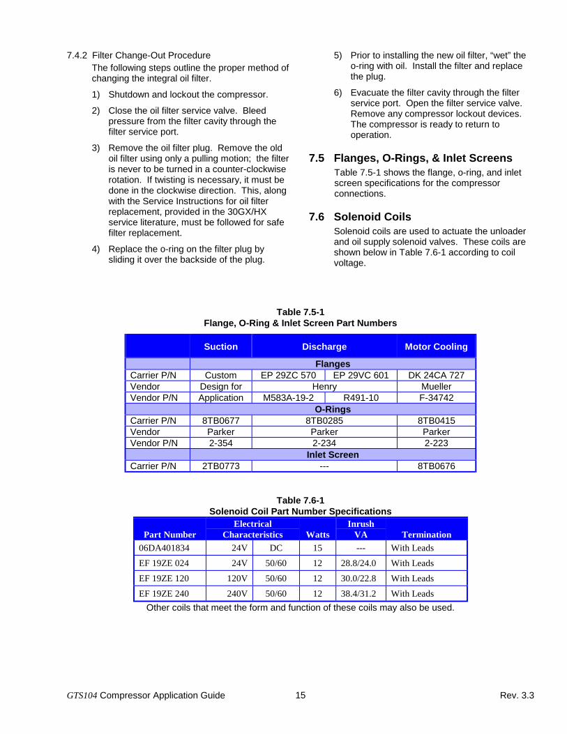
7.5 Flanges, O-Rings, & Inlet ScreensTable 7.5-1 shows the flange, o-ring, and inletscreen specifications for the compressorconnections.
7.6 Solenoid CoilsSolenoid coils are used to actuate the unloaderand oil supply solenoid valves. These coils areshown below in Table 7.6-1 according to coilvoltage.
Table 7.5-1Flange, O-Ring & Inlet Screen Part Numbers
Suction Discharge Motor Cooling
FlangesCarrier P/N Custom EP 29ZC 570 EP 29VC 601 DK 24CA 727Vendor Design for Henry MuellerVendor P/N Application M583A-19-2 R491-10 F-34742
O-RingsCarrier P/N 8TB0677 8TB0285 8TB0415Vendor Parker Parker ParkerVendor P/N 2-354 2-234 2-223
Inlet ScreenCarrier P/N 2TB0773 --- 8TB0676
Table 7.6-1Solenoid Coil Part Number Specifications
Part NumberElectrical
Characteristics WattsInrush
VA Termination06DA401834 24V DC 15 --- With Leads
EF 19ZE 024 24V 50/60 12 28.8/24.0 With Leads
EF 19ZE 120 120V 50/60 12 30.0/22.8 With Leads
EF 19ZE 240 240V 50/60 12 38.4/31.2 With Leads
Other coils that meet the form and function of these coils may also be used.
GTS104 Compressor Application Guide Rev. 3.316
7.7 Mating Electrical ConnectionsThe terminal pin connections for the GTS104compressor are M12 metric thread. Electricalhardware for making the power connections isstandard with each compressor in the JumperBar Accessory Kit, part number 0TB0673. Referto the Compressor Application Drawing,0TB0410, for torque specifications, and theproper installation of the power terminalhardware for both the Delta start-Delta runconfiguration (Across the Line), and the Wyestart-Delta Run configuration.
The motor winding thermistor connections are1/4" spade terminals.
7.8 Oil Supply Solenoid ValveThe oil supply solenoid valve is required toisolate the compressor from oil flow when thecompressor is not operating. The oil supplysolenoid valve is field replaceable; thereplacement part number is 8TB0884.
7.9 Unloader Solenoid ValvesThe unloader solenoid valves are required toactuate the poppet unloaders of the compressor.The unloader solenoid valves are fieldreplaceable; the replacement part number is8TA0049D.
7.10 Compressor Protection ModuleThe compressor protection modules (CPM) areset-up in the Carrier Purchased Parts system aspart numbers HN 67LM 100 and HN 67LM 101.
7.11 External MufflerAn external muffler is available, Carlyle partnumber 2TB0646, and can be piped into thedischarge line of the compressor that will furtherreduce the discharge gas pressure pulsationsleaving the compressor. The addition of theexternal muffler will reduce radiated noise levelsfrom other system components that can beexcited by the gas pulsations. Sound treatmentis recommended on the discharge line betweenthe compressor and the muffler.
The muffler can be included into horizontal andvertically flowing pipes, without respect to anyparticular orientation. The sound reductionmaterial in the muffler will absorb approximately2 liters (0.5 gallon) of oil that should be takeninto account when the system oil charge iscalculated. The maximum working pressure forthe muffler is 31 bar (450 psig).
GTS104 Compressor Application Guide 17 Rev. 3.3
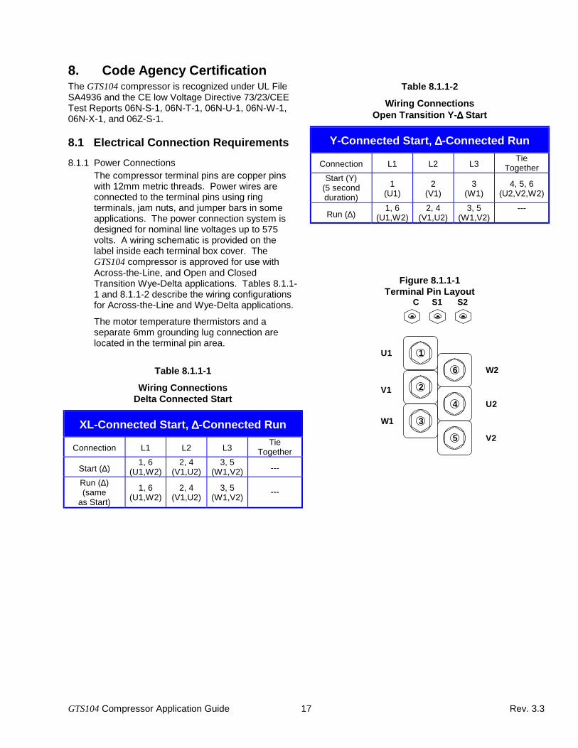
8. Code Agency CertificationThe GTS104 compressor is recognized under UL FileSA4936 and the CE low Voltage Directive 73/23/CEETest Reports 06N-S-1, 06N-T-1, 06N-U-1, 06N-W-1,06N-X-1, and 06Z-S-1.
8.1 Electrical Connection Requirements
8.1.1 Power ConnectionsThe compressor terminal pins are copper pinswith 12mm metric threads. Power wires areconnected to the terminal pins using ringterminals, jam nuts, and jumper bars in someapplications. The power connection system isdesigned for nominal line voltages up to 575volts. A wiring schematic is provided on thelabel inside each terminal box cover. TheGTS104 compressor is approved for use withAcross-the-Line, and Open and ClosedTransition Wye-Delta applications. Tables 8.1.1-1 and 8.1.1-2 describe the wiring configurationsfor Across-the-Line and Wye-Delta applications.
The motor temperature thermistors and aseparate 6mm grounding lug connection arelocated in the terminal pin area.
Table 8.1.1-1
Wiring ConnectionsDelta Connected Start
XL-Connected Start, ∆∆∆∆-Connected Run
Connection L1 L2 L3Tie
Together
Start (∆)1, 6
(U1,W2)2, 4
(V1,U2)3, 5
(W1,V2) ---
Run (∆)(same
as Start)
1, 6(U1,W2)
2, 4(V1,U2)
3, 5(W1,V2)
---
Table 8.1.1-2
Wiring ConnectionsOpen Transition Y-∆∆∆∆ Start
Y-Connected Start, ∆∆∆∆-Connected Run
Connection L1 L2 L3Tie
TogetherStart (Y)
(5 secondduration)
1(U1)
2(V1)
3(W1)
4, 5, 6(U2,V2,W2)
Run (∆)1, 6
(U1,W2)2, 4
(V1,U2)3, 5
(W1,V2)---
Figure 8.1.1-1Terminal Pin Layout
1
2
3
6
4
5
U1
V1
W1
W2
U2
V2
C S1 S2
GTS104 Compressor Application Guide 18 Rev. 3.3
8.1.2 Wye-Delta StartingThere are two critical timing parameters associatedwith starting the GTS104 compressor with an opentransition Wye-Delta starter. The first is themaximum duration of running in the wye connection.It is recommended that the duration of the wyeconnection be 5 seconds. The duration of the wyeconnection can be longer but in any case should notexceed 10 seconds. This is necessary to limit thepotential for excessive heating of the motor.The second critical timing parameter is the durationof the power interruption from when the wyeconnection is broken to when the delta connection ismade. It is recommended that the duration of thisinterruption not exceed 49 milliseconds. Starterselections should be made such that this limit is notexceeded. Longer interruption times could lead toexcessive deceleration during the power interruption.Low running speed at transition will result in inrushcurrents similar to the delta locked rotor current.
8.1.3 Terminal BoxThe terminal box is designed in accordance withUL 984, UL 1995, CSA, for the North Americanmarket, IEC 529, and EN 60204; IP 43, andIP 54 for the European market.
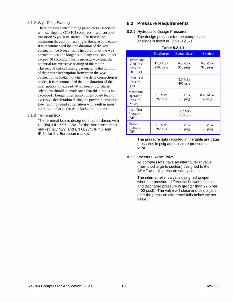
8.2 Pressure Requirements
8.2.1 Hydrostatic Design PressuresThe design pressure for the compressorcastings is listed in Table 8.2.1-1.
Table 8.2.1-1Discharge Economizer Suction
HydrostaticBurst TestPressure(BURST)
17.3 MPa2500 psig
6.9 MPa986 psig
6.9 MPa986 psig
Proof TestPressure(TP)
3.3 MPa460 psig
MaximumOperatingPressure(MOP)
2.1 MPa292 psig
1.3 MPa176 psig
0.45 MPa52 psig
Leak TestPressure(AP)
2.2 MPa310 psig
DesignPressure(DP)
2.1 MPa292 psig
1.3 MPa176 psig
1.3 MPa176 psig
The pressure data reported in the table are gagepressures in psig and absolute pressures inMPa.
8.2.2 Pressure Relief ValveAll compressors have an internal relief valve(from discharge to suction) designed to theASME and UL pressure safety codes.
The internal relief valve is designed to openwhen the pressure differential between suctionand discharge pressure is greater than 27.6 bar,(400 psid). The valve will close and seal againafter the pressure difference falls below the setvalue.

GTS104 Compressor Application Guide 19 Rev. 3.3
9. Packaging and Storage Requirements9.1. Packaging
Packaging for the GTS104 screw compressorconsists of a returnable plastic container and aplastic wood insert to position the compressorinside the container. The compressor isattached to the insert by two bolts. One boltattaches the compressor through a hole in thesuction blank-off plate, and another bolt fastensthe compressor at the end of the motor casingthrough a bracket that is attached to the motorcasing.
The bracket is a permanent part of thecompressor installed on the compressor prior tothe painting process. THIS BRACKET MUSTREMAIN ATTACHED TO THE COMPRESSOR.Failure to do so could jeopardize the corrosionresistance of the compressor.
9.2. ShippingAll compressors that are shipped within the U.S.will be unstacked (single layer). Compressorsthat are intended for international shipment maybe stacked depending upon the mode ofshipment. Any compressors that will be stackedduring shipping will require special packagingconsideration. Consult Carlyle Compressor forthese requirements.
The stacking limit for shipping is two high.
Compressor weights are shown in Table 9.2-1.
9.3. StorageThe compressor packaging allows for stackingof the compressors during storage.
The stacking limit for storage is three high.
Although the GTS104 compressors are painted inorder to meet the 500 hours salt sprayrequirements, it is preferable to store thecompressors indoors where they are shieldedfrom the weather. Outdoor storage is alsopermissible.
Table 9.2-1Compressor Weights
CompressorModel
CompressorWeight
ShippingWeight
Number lb. kg. lb. kg.
Economized06NA-123--E- 835 380 955 43506NA-146--E- 855 390 975 44506NA-174--E- 880 400 1000 45506NA-209--E- 895 405 1015 46006NA-250--E- 910 415 1030 47006NA-300--E- 920 415 1040 47506NW-146--E- 805 365 925 42006NW-174--E- 825 375 945 43006NW-209--E- 835 380 955 43506NW-250--E- 855 390 975 44506NW-300--E- 880 400 1000 455
Non-Economized06NA-123--N- 825 375 945 43006NA-146--N- 835 380 955 43506NA-174--N- 855 390 975 44506NA-209--N- 880 400 1000 45506NA-250--N- 895 405 1015 46006NA-300--N- 910 415 1030 47006NW-123--N- 795 360 915 41506NW-146--N- 795 360 915 41506NW-174--N- 805 365 925 42006NW-209--N- 825 375 945 43006NW-250--N- 835 380 955 43506NW-300--N- 855 390 975 445
The compressor weight is without packaging. The shippingweight includes the weight of the compressor, returnablepackaging, and cover plates.
GTS104 Compressor Application Guide 20 Rev. 3.3
10. Compressor Electrical Data
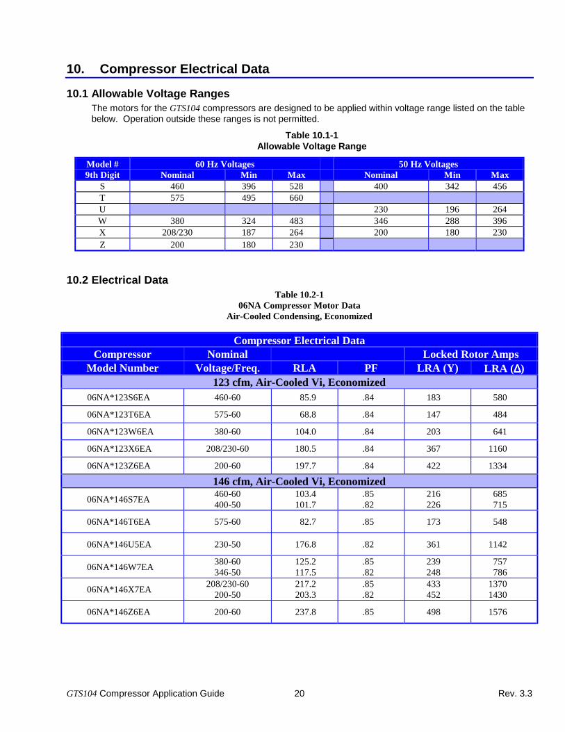
10.1 Allowable Voltage RangesThe motors for the GTS104 compressors are designed to be applied within voltage range listed on the tablebelow. Operation outside these ranges is not permitted.
Table 10.1-1Allowable Voltage Range
Model # 60 Hz Voltages 50 Hz Voltages9th Digit Nominal Min Max Nominal Min Max
S 460 396 528 400 342 456T 575 495 660U 230 196 264W 380 324 483 346 288 396X 208/230 187 264 200 180 230Z 200 180 230
10.2 Electrical DataTable 10.2-1
06NA Compressor Motor DataAir-Cooled Condensing, Economized
Compressor Electrical DataCompressor Nominal Locked Rotor Amps
Model Number Voltage/Freq. RLA PF LRA (Y) LRA (∆∆∆∆)123 cfm, Air-Cooled Vi, Economized
06NA*123S6EA 460-60 85.9 .84 183 580
06NA*123T6EA 575-60 68.8 .84 147 484
06NA*123W6EA 380-60 104.0 .84 203 641
06NA*123X6EA 208/230-60 180.5 .84 367 1160
06NA*123Z6EA 200-60 197.7 .84 422 1334
146 cfm, Air-Cooled Vi, Economized
06NA*146S7EA460-60400-50
103.4101.7
.85
.82216226
685715
06NA*146T6EA 575-60 82.7 .85 173 548
06NA*146U5EA 230-50 176.8 .82 361 1142
06NA*146W7EA380-60346-50
125.2117.5
.85
.82239248
757786
06NA*146X7EA208/230-60
200-50217.2203.3
.85
.82433452
13701430
06NA*146Z6EA 200-60 237.8 .85 498 1576

GTS104 Compressor Application Guide 21 Rev. 3.3
Compressor Nominal Locked Rotor AmpsModel Number Voltage/Freq. RLA PF LRA (Y) LRA (∆∆∆∆)
174 cfm, Air-Cooled Vi, Economized
06NA*174S7EA460-60400-50
125.0123.1
.86
.83259270
820856
06NA*174T6EA 575-60 100.0 .86 207 656
06NA*174U5EA 230-50 214.1 .83 432 1367
06NA*174W7EA380-60346-50
151.3142.3
.86
.83286297
906941
06NA*174X7EA208/230-60
200-50262.6246.2
.86
.83518541
16401711
06NA*174Z6EA 200-60 287.5 .86 596 1886
209 cfm, Air-Cooled Vi, Economized
06NA*209S7EA460-60400-50
152.0147.4
.87
.84291303
920960
06NA*209T6EA 575-60 121.6 .87 233 736
06NA*209U5EA 230-50 256.4 .84 485 1533
06NA*209W7EA380-60346-50
184.0170.4
.87
.84321334
10171056
06NA*209X7EA208/230-60
200-50319.2294.8
.87
.84581607
18401920
06NA*209Z6EA 200-60 349.6 .87 669 2116
250 cfm, Air-Cooled Vi, Economized
06NA*250S7EA460-60400-50
185.3178.8
.85
.82371387
11751226
06NA*250T6EA 575-60 148.3 .85 297 940
06NA*250U5EA 230-50 310.9 .82 619 1958
06NA*250W7EA380-60346-50
224.3206.7
.85
.82410426
12991348
06NA*250X7EA208/230-60
200-50389.3357.5
.85
.82743775
23502452
06NA*250Z6EA 200-60 426.3 .85 854 2703
300 cfm, Air-Cooled Vi, Economized
06NA*300S5EA 400-50 221.8 .86 400 1265
06NA*300U5EA 230-50 385.8 .86 638 2020
06NA*300W5EA 346-50 256.4 .86 439 1391
06NA*300X5EA 200-50 443.7 .86 799 2529

GTS104 Compressor Application Guide 22 Rev. 3.3
Table 10.2-206NW Compressor Motor Data
Water-Cooled Condensing, Economized
Compressor Electrical DataCompressor Nominal Locked Rotor Amps
Model Number Voltage/Freq. RLA PF LRA (Y) LRA (∆∆∆∆)123 cfm, Water-Cooled Vi, Economized
Model Not AvailableUse as Equal Alternate 06NW*123*6NA
123 cfm, Water-Cooled Vi, Non-Economized
146 cfm, Water-Cooled Vi, Economized
06NW*146S7EA460-60400-50
68.267.1
.86
.84128134
405423
06NW*146T6EA 575-60 54.6 .86 102 324
06NW*146U5EA 230-50 116.7 .84 213 675
06NW*146W7EA380-60346-50
82.677.6
.86
.84141147
448465
06NW*146X7EA208/230-60
200-50143.3134.2
.86
.84256267
810845
06NW*146Z6EA 200-60 156.9 .86 294 932
174 cfm, Water-Cooled Vi, Economized
06NW*174S7EA460-60400-50
83.481.5
.87
.85153160
485506
06NW*174T6EA 575-60 66.7 .87 123 388
06NW*174U5EA 230-50 141.7 .85 255 808
06NW*174W7EA380-60346-50
100.994.2
.87
.85169176
536556
06NW*174X7EA208/230-60
200-50175.1162.9
.87
.85307320
9701012
06NW*174Z6EA 200-60 191.8 .87 352 1116

GTS104 Compressor Application Guide 23 Rev. 3.3
Compressor Nominal Locked Rotor AmpsModel Number Voltage/Freq. RLA PF LRA (Y) LRA (∆∆∆∆)
209 cfm, Water-Cooled Vi, Economized
06NW*209S7EA460-60400-50
100.898.2
.88
.86183191
580605
06NW*209T6EA 575-60 80.6 .88 147 484
06NW*209U5EA 230-50 170.9 .86 305 967
06NW209W7EA380-60346-50
122.0113.6
.88
.86203210
641665
06NW*209X7EA208/230-60
200-50211.8196.5
.88
.86367382
11601210
06NW*209Z6EA 200-60 231.9 .88 422 1334
250 cfm, Water-Cooled Vi, Economized
06NW*250S7EA460-60400-50
120.7117.9
.88
.86216226
685715
06NW*250T6EA 575-60 96.6 .88 173 548
06NW*250U5EA 230-50 205.0 .86 361 1142
06NW*250W7EA380-60346-50
146.1136.6
.88
.86239248
757786
06NW*250X7EA208/230-60
200-50253.6235.7
.88
.86433452
13701430
06NW*250Z6EA 200-60 277.7 .88 498 1576
300 cfm, Water-Cooled Vi, Economized
06NW*300S5EA 400-50 143.3 .87 270 856
06NW*300U5EA 230-50 249.2 .87 432 1367
06NW*300W5EA 346-50 165.7 .87 297 941
06NW*300X5EA 200-50 286.6 .87 541 1711

GTS104 Compressor Application Guide 24 Rev. 3.3
Table 10.2-306NA Compressor Motor Data
Air-Cooled Condensing, Non-Economized
Compressor Electrical DataCompressor Nominal Locked Rotor Amps
Model Number Voltage/Freq. RLA PF LRA (Y) LRA (∆∆∆∆)123 cfm, Air-Cooled Vi, Non-Economized
06NA*123S6NA 460-60 76.5 .87 153 485
06NA*123T6NA 575-60 61.2 .87 123 388
06NA*123W6NA 380-60 92.6 .87 169 536
06NA*123X6NA 208/230-60 160.7 .87 307 970
06NA*123Z6NA 200-60 176.0 .87 352 1116
146 cfm, Air-Cooled Vi, Non-Economized
06NA*146S7NA460-60400-50
91.990.1
.87
.85183191
580605
06NA*146T6NA 575-60 73.5 .87 147 484
06NA*146U5NA 230-50 156.8 .85 305 967
06NA*146W7NA380-60346-50
111.2104.2
.87
.85203210
641665
06NA*146X7NA208/230-60
200-50192.9180.3
.87
.85367382
11601210
06NA*146Z6NA 200-60 211.3 .87 422 1334
174 cfm, Air-Cooled Vi, Non-Economized
06NA*174S7NA460-60400-50
112.2109.7
.85
.82216226
685715
06NA*174T6NA 575-60 89.7 .85 173 548
06NA*174U5NA 230-50 190.7 .82 361 1142
06NA*174W7NA380-60346-50
135.8126.8
.85
.85239248
757786
06NA*174X7NA208/230-60
200-50235.6219.3
.85
.82433452
13701430
06NA*174Z6NA 200-60 257.9 .85 498 1576

GTS104 Compressor Application Guide 25 Rev. 3.3
Compressor Nominal Locked Rotor AmpsModel Number Voltage/Freq. RLA PF LRA (Y) LRA (∆∆∆∆)
209 cfm, Air-Cooled Vi, Non-Economized
06NA*209S7NA460-60400-50
136.4132.5
.86
.83259270
820856
06NA*209T6NA 575-60 109.2 .86 207 656
06NA*209U5NA 230-50 230.5 .83 432 1367
06NA*209W7NA380-60346-50
165.2163.2
.86
.83286297
906941
06NA*209X7NA208/230-60
200-50286.6265.1
.86
.83518541
16401711
06NA*209Z6NA 200-60 313.8 .86 596 1886
250 cfm, Air-Cooled Vi, Non-Economized
06NA*250S7NA460-60400-50
166.1160.7
.87
.84291303
920960
06NA*250T6NA 575-60 132.9 .87 233 736
06NA*250U5NA 230-50 279.4 .84 485 1533
06NA*250W7NA380-60346-50
201.0185.7
.87
.84321334
10171056
06NA*250X7NA208/230-60
200-50348.9321.3
.87
.84581607
18401920
06NA*250Z6NA 200-60 382.0 .87 669 2116
300 cfm, Air-Cooled Vi, Non-Economized
06NA*300S5NA 400-50 197.5 .82 387 1226
06NA*300U5NA 230-50 343.5 .82 619 1958
06NA*300W5NA 346-50 228.4 .82 426 1348
06NA*300X5NA 200-50 395.1 .82 775 2452

GTS104 Compressor Application Guide 26 Rev. 3.3
Table 10.2-406NW Compressor Motor Data
Water-Cooled Condensing, Non-Economized
Compressor Electrical DataCompressor Nominal Locked Rotor Amps
Model Number Voltage/Freq. RLA PF LRA (Y) LRA (∆∆∆∆)123 cfm, Water-Cooled Vi, Non-Economized
06NW*123S6NA 460-60 51.8 .86 104 330
06NW*123T6NA 575-60 41.5 .86 83 264
06NW*123W6NA 380-60 62.7 .86 115 365
06NW*123X6NA 208/230-60 108.9 .86 209 660
06NW*123Z6NA 200-60 119.2 .86 240 759
146 cfm, Water-Cooled Vi, Non-Economized
06NW*146S7NA460-60400-50
62.661.6
.86
.83104109
330344
06NW*146T6NA 575-60 50.1 .86 83 264
06NW*146U5NA 230-50 107.2 .83 174 550
06NW*146W7NA380-60346-50
75.871.3
.86
.83115120
365379
06NW*146X7NA208/230-60
200-50131.5123.3
.86
.83209218
660689
06NW*146Z6NA 200-60 144.0 .86 240 759
174 cfm, Water-Cooled Vi, Non-Economized
06NW*174S7NA460-60400-50
76.474.8
.86
.84128134
405423
06NW*174T6NA 575-60 61.1 .86 102 324
06NW*174U5NA 230-50 130.1 .84 213 675
06NW*174W7NA380-60346-50
92.586.5
.86
.84141147
448465
06NW*174X7NA208/230-60
200-50160.5149.6
.86
.84256267
810845
06NW*174Z6NA 200-60 175.8 .86 294 932

GTS104 Compressor Application Guide 27 Rev. 3.3
Compressor Nominal Locked Rotor AmpsModel Number Voltage/Freq. RLA PF LRA (Y) LRA (∆∆∆∆)
209 cfm, Water-Cooled Vi, Non-Economized
06NW*209S7NA460-60400-50
92.590.2
.87
.85153160
485506
06NW*209T6NA 575-60 74.0 .87 123 388
06NW*209U5NA 230-50 156.9 .85 255 808
06NW*209W7NA380-60346-50
112.0104.3
.87
.85169176
536556
06NW*209X7NA208/230-60
200-50194.3180.5
.87
.85307320
9701012
06NW*209Z6NA 200-60 212.8 .87 352 1116
250 cfm, Water-Cooled Vi, Non-Economized
06NW*250S7NA460-60400-50
110.8108.1
.88
.86183191
580605
06NW*250T6NA 575-60 88.7 .88 147 484
06NW*250U5NA 230-50 188.1 .86 305 967
06NW*250W7NA380-60346-50
134.1125.0
.88
.86203210
641665
06NW*250X7NA208/230-60
200-50232.8216.3
.88
.86367382
11601210
06NW*250Z6NA 200-60 254.9 .88 422 1334
300 cfm, Water-Cooled Vi, Non-Economized
06NW*300S5NA 400-50 131.3 .86 226 715
06NW*300U5NA 230-50 228.4 .86 361 1142
06NW*300W5NA 346-50 151.8 .86 248 786
06NW*300X5NA 200-50 262.6 .86 452 1430
RLA Rated Load Amps is determined based on theMust Hold (MHA) and Must Trip Amp (MTA)values for the compressor. Each of theserelationships are shown in the followingequations:
RLA MTA
MTA MHA
MHA I Max LoadVoltage
= ÷= ×=
−
1 40
1 15
15
.
.
%
PF Power Factor is listed for the nominal loadcondition.
The maximum load condition for thecompressors are:
SST / SDT / SUPH / SUBC
06NA: 12.8 / 70 / 8 / 10(55 / 158 / 14 / 18)
06NW: 12.8 / 50 / 8 / 3(55 / 122 / 14 / 5)
The nominal load conditions are:
06NA: 4.7 / 53 / 0 / 14(40.5 / 128 / 0 / 25)
06NW: 4.7 / 41 / 0 / 3(40.5 / 105 / 0 / 5)

GTS104 Compressor Application Guide 28 Rev. 3.3
10.3 Motor Winding ThermistorThe motor winding thermistor is embeddeddirectly into the windings of the motor. Thethermistor is an NTC type with a standardresistance of 5000Ω at 25°C. Table 10.3-1lists the resistance versus temperaturecharacteristics.
Additional information regarding this sensor canbe obtained from Carrier drawing 32MP500354.
Table 10.3-1
Motor Temperature ThermistorTemperature vs Resistance Characteristics
TEMPERATURE RESISTANCE°°°°C ±±±±°°°°C °°°°F ΩΩΩΩ (ohms)-30 .35 -22 88480-25 .33 -13 65205-20 .30 -4 48536-15 .28 5 36476-10 .25 14 27663
-5 .23 23 211630 .20 32 163255 .20 41 12696
10 .20 50 9949.515 .20 59 7855.520 .20 68 6246.025 .20 77 5000.030 .20 86 4028.435 .20 95 3265.740 .20 104 2663.245 .20 113 2184.250 .20 122 1801.255 .20 131 1493.160 .20 140 1243.965 .20 149 1041.470 .20 158 875.875 .23 167 739.780 .26 176 627.685 .29 185 534.990 .32 194 457.795 .35 203 393.3
100 .38 212 339.3105 .41 221 293.8110 .44 230 255.3115 .47 239 222.6120 .50 248 194.8
GTS104 Compressor Application Guide 29 Rev. 3.3
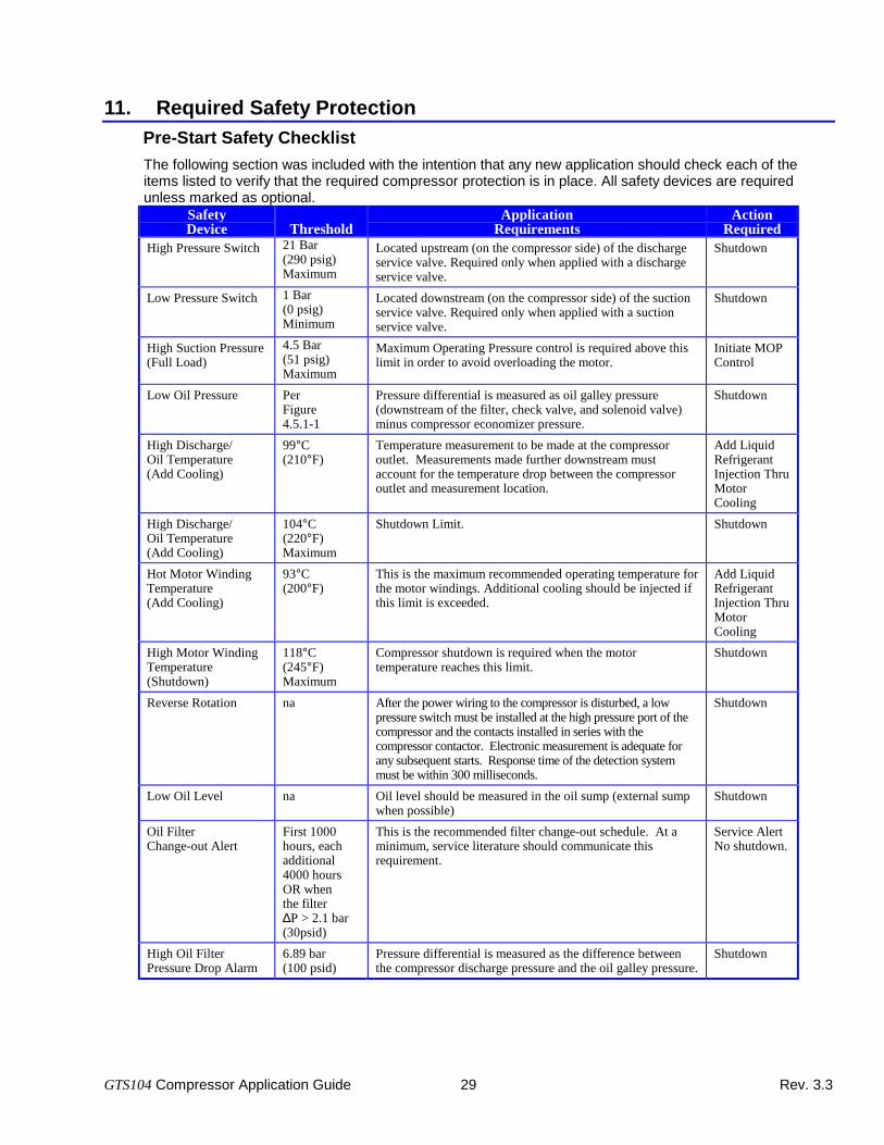
11. Required Safety ProtectionPre-Start Safety Checklist
The following section was included with the intention that any new application should check each of theitems listed to verify that the required compressor protection is in place. All safety devices are requiredunless marked as optional.
SafetyDevice Threshold
ApplicationRequirements
ActionRequired
High Pressure Switch 21 Bar(290 psig)Maximum
Located upstream (on the compressor side) of the dischargeservice valve. Required only when applied with a dischargeservice valve.
Shutdown
Low Pressure Switch 1 Bar(0 psig)Minimum
Located downstream (on the compressor side) of the suctionservice valve. Required only when applied with a suctionservice valve.
Shutdown
High Suction Pressure(Full Load)
4.5 Bar(51 psig)Maximum
Maximum Operating Pressure control is required above thislimit in order to avoid overloading the motor.
Initiate MOPControl
Low Oil Pressure PerFigure4.5.1-1
Pressure differential is measured as oil galley pressure(downstream of the filter, check valve, and solenoid valve)minus compressor economizer pressure.
Shutdown
High Discharge/Oil Temperature(Add Cooling)
99°C(210°F)
Temperature measurement to be made at the compressoroutlet. Measurements made further downstream mustaccount for the temperature drop between the compressoroutlet and measurement location.
Add LiquidRefrigerantInjection ThruMotorCooling
High Discharge/Oil Temperature(Add Cooling)
104°C(220°F)Maximum
Shutdown Limit. Shutdown
Hot Motor WindingTemperature(Add Cooling)
93°C(200°F)
This is the maximum recommended operating temperature forthe motor windings. Additional cooling should be injected ifthis limit is exceeded.
Add LiquidRefrigerantInjection ThruMotorCooling
High Motor WindingTemperature(Shutdown)
118°C(245°F)Maximum
Compressor shutdown is required when the motortemperature reaches this limit.
Shutdown
Reverse Rotation na After the power wiring to the compressor is disturbed, a lowpressure switch must be installed at the high pressure port of thecompressor and the contacts installed in series with thecompressor contactor. Electronic measurement is adequate forany subsequent starts. Response time of the detection systemmust be within 300 milliseconds.
Shutdown
Low Oil Level na Oil level should be measured in the oil sump (external sumpwhen possible)
Shutdown
Oil FilterChange-out Alert
First 1000hours, eachadditional4000 hoursOR whenthe filter∆P > 2.1 bar(30psid)
This is the recommended filter change-out schedule. At aminimum, service literature should communicate thisrequirement.
Service AlertNo shutdown.
High Oil FilterPressure Drop Alarm
6.89 bar(100 psid)
Pressure differential is measured as the difference betweenthe compressor discharge pressure and the oil galley pressure.
Shutdown

Manufacturer reserves the rightto discontinue, or change at anytime, specifications or designswithout notice and withoutincurring obligations.
Carlyle Compressor Company Carrier Corporation 10/99P.O. Box 4803, Syracuse, NY 13221Phone: In US & Mexico 1-800-GO-CARLYLE
In Canada & Puerto Rico 1-800-258-1123
Lit. No. 574-076
GTS104 Compressor Application GuideRevision 3.3