Mfc
4
170 171 TELE-audiovision International — The World‘s Largest Digital TV Trade Magazine — 11-12/2013 — www.TELE-audiovision.com www.TELE-audiovision.com — 11-12/2013 — TELE-audiovision International — 全球发行量最大的数字电视杂志 PRODUCT REPORT • Filtros HF para todos os tipos de aplicações • enorme sucesso no segmento do filtro de banda C • filtros altamente especializados para evitar a interferência WiMAX, entre outras • filtros hight-pass e filtros low-pass podem ser combinados para substituir os filtros de separação-de-frequência Filtros Feitos pela MFC Filtros de Alta-frequência
-
Upload
tele-satellite-por -
Category
Documents
-
view
250 -
download
3
description
Transcript of Mfc

170 171TELE-audiovision International — The World‘s Largest Digital TV Trade Magazine — 11-12/2013 — www.TELE-audiovision.com www.TELE-audiovision.com — 11-12/2013 — TELE-audiovision International — 全球发行量最大的数字电视杂志
PRODUCT REPORT
• Filtros HF para todos os tipos de aplicações • enorme sucesso no segmento do filtro de banda C • filtros altamente especializados para evitar a interferência WiMAX, entre outras• filtros hight-pass e filtros low-pass podem ser combinados para substituir os filtros de separação-de-frequência
Filtros Feitos pela MFC
Filtros de Alta-frequência
1
2
3
54
172 TELE-audiovision International — The World‘s Largest Digital TV Trade Magazine — 11-12/2013 — www.TELE-audiovision.com
PRODUCT REPORT High-Frequency Filters
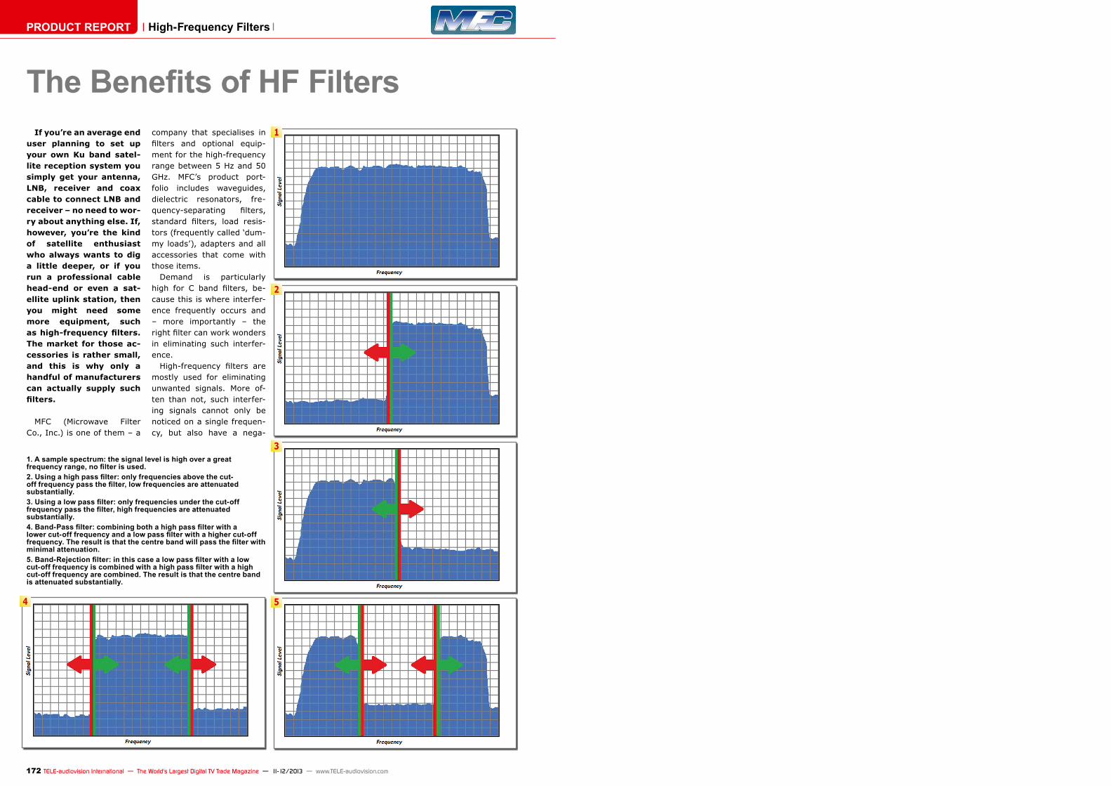
The Benefits of HF FiltersIf you’re an average end
user planning to set up your own Ku band satel-lite reception system you simply get your antenna, LNB, receiver and coax cable to connect LNB and receiver – no need to wor-ry about anything else. If, however, you’re the kind of satellite enthusiast who always wants to dig a little deeper, or if you run a professional cable head-end or even a sat-ellite uplink station, then you might need some more equipment, such as high-frequency filters. The market for those ac-cessories is rather small, and this is why only a handful of manufacturers can actually supply such filters.
MFC (Microwave Filter Co., Inc.) is one of them – a
company that specialises in filters and optional equip-ment for the high-frequency range between 5 Hz and 50 GHz. MFC’s product port-folio includes waveguides, dielectric resonators, fre-quency-separating filters, standard filters, load resis-tors (frequently called ‘dum-my loads’), adapters and all accessories that come with those items.
Demand is particularly high for C band filters, be-cause this is where interfer-ence frequently occurs and – more importantly – the right filter can work wonders in eliminating such interfer-ence.
High-frequency filters are mostly used for eliminating unwanted signals. More of-ten than not, such interfer-ing signals cannot only be noticed on a single frequen-cy, but also have a nega-
1. A sample spectrum: the signal level is high over a great frequency range, no filter is used.2. Using a high pass filter: only frequencies above the cut-off frequency pass the filter, low frequencies are attenuated substantially.3. Using a low pass filter: only frequencies under the cut-off frequency pass the filter, high frequencies are attenuated substantially.4. Band-Pass filter: combining both a high pass filter with a lower cut-off frequency and a low pass filter with a higher cut-off frequency. The result is that the centre band will pass the filter with minimal attenuation.5. Band-Rejection filter: in this case a low pass filter with a low cut-off frequency is combined with a high pass filter with a high cut-off frequency are combined. The result is that the centre band is attenuated substantially.
Model 18253 - C-Band (INSAT) Transmit Reject Filter• This TRF provides deep rejection of the transmit band with minimal effect on the receive band.• Ideal for INSAT and other Region-Specific Receive Applications• Alternate Flange Configurations are Available Upon Request
Pass band 4.5 - 4.8 GHz (C-INSAT Downlink)Insertion Loss 0.50 dB MaxVSWR 1.30:1 MaxReject Band 6.725 - 7.025 GHz (C-INSAT Uplink)Rejection 80 dB MinOperating Temperature Range -10°C to +60°CFlanges CPR229GDimensions 3.95” x 3.88” x 2.75” (100mm x 98mm x 70mm)Finish Gloss White Lacquer
Model 18323 - C-Band (INSAT) Receive Reject Filter
• Same as before but rejection of the receive (Downlink) bandPassband 6.725 - 7.025 GHzInsertion Loss 0.10 dB Approx.VSWR 1.22:1 MaxReject Band 4.5 - 4.8 GHzRejection 80 dB TypFlanges CPR137/CPR137GDimensions 5.00“ x 2.69“ x 1.94“ (127mm x 68mm x 49mm)Finish White Lacquer
Model 18506 - Multi-Purpose C-Band Transmit Filter
• This Uplink filter not only rejects the entire receive band (below 4.2 GHz), but it also rejects transmissions from other potential sources of interference etc., that RRFs do not.• Ideal for use in high-density transmit paths, like:
Wireless Services (Point-Multipoint) 4.55 - 4.9 GHzMaritime & Aeronautical Radio Navigation 4.2 - 5.6 GHzBroadcast Auxiliary Services 6.95 -7.15 GHz
• Ideal for all “standard band” C-Band Uplink Applications• Easy bolt-on installation and no power supply required
Passband 5.925 - 6.425 GHzPassband Loss 0.3 dB MaxPassband Return Loss 17.7 dB MinRejection 50 dB Min @ 5.625 GHz 40 dB Min @ 6.725 GHzPower Rating 400 WattsFlanges CPR137FDimensions 9.50” x 2.69” x 1.94” (241mm x 68mm x 49mm)Finish Gloss White Lacquer
■
■
174 175TELE-audiovision International — The World‘s Largest Digital TV Trade Magazine — 11-12/2013 — www.TELE-audiovision.com www.TELE-audiovision.com — 11-12/2013 — TELE-audiovision International — 全球发行量最大的数字电视杂志
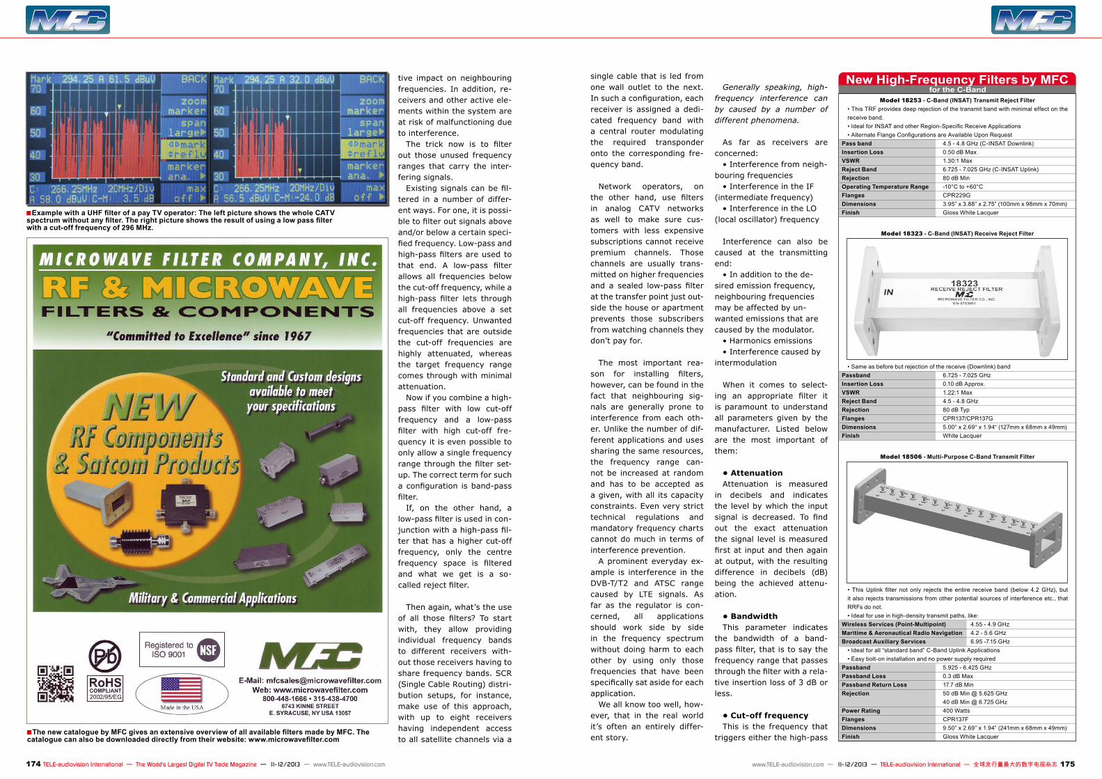
Example with a UHF filter of a pay TV operator: The left picture shows the whole CATV spectrum without any filter. The right picture shows the result of using a low pass filter with a cut-off frequency of 296 MHz.
tive impact on neighbouring frequencies. In addition, re-ceivers and other active ele-ments within the system are at risk of malfunctioning due to interference.
The trick now is to filter out those unused frequency ranges that carry the inter-fering signals.
Existing signals can be fil-tered in a number of differ-ent ways. For one, it is possi-ble to filter out signals above and/or below a certain speci-fied frequency. Low-pass and high-pass filters are used to that end. A low-pass filter allows all frequencies below the cut-off frequency, while a high-pass filter lets through all frequencies above a set cut-off frequency. Unwanted frequencies that are outside the cut-off frequencies are highly attenuated, whereas the target frequency range comes through with minimal attenuation.
Now if you combine a high-pass filter with low cut-off frequency and a low-pass filter with high cut-off fre-quency it is even possible to only allow a single frequency range through the filter set-up. The correct term for such a configuration is band-pass filter.
If, on the other hand, a low-pass filter is used in con-junction with a high-pass fil-ter that has a higher cut-off frequency, only the centre frequency space is filtered and what we get is a so-called reject filter.
Then again, what’s the use of all those filters? To start with, they allow providing individual frequency bands to different receivers with-out those receivers having to share frequency bands. SCR (Single Cable Routing) distri-bution setups, for instance, make use of this approach, with up to eight receivers having independent access to all satellite channels via a
single cable that is led from one wall outlet to the next. In such a configuration, each receiver is assigned a dedi-cated frequency band with a central router modulating the required transponder onto the corresponding fre-quency band.
Network operators, on the other hand, use filters in analog CATV networks as well to make sure cus-tomers with less expensive subscriptions cannot receive premium channels. Those channels are usually trans-mitted on higher frequencies and a sealed low-pass filter at the transfer point just out-side the house or apartment prevents those subscribers from watching channels they don’t pay for.
The most important rea-son for installing filters, however, can be found in the fact that neighbouring sig-nals are generally prone to interference from each oth-er. Unlike the number of dif-ferent applications and uses sharing the same resources, the frequency range can-not be increased at random and has to be accepted as a given, with all its capacity constraints. Even very strict technical regulations and mandatory frequency charts cannot do much in terms of interference prevention.
A prominent everyday ex-ample is interference in the DVB-T/T2 and ATSC range caused by LTE signals. As far as the regulator is con-cerned, all applications should work side by side in the frequency spectrum without doing harm to each other by using only those frequencies that have been specifically sat aside for each application.
We all know too well, how-ever, that in the real world it’s often an entirely differ-ent story.
Generally speaking, high-frequency interference can by caused by a number of different phenomena.
As far as receivers are concerned:
• Interference from neigh-bouring frequencies
• Interference in the IF (intermediate frequency)
• Interference in the LO (local oscillator) frequency
Interference can also be caused at the transmitting end:
• In addition to the de-sired emission frequency, neighbouring frequencies may be affected by un-wanted emissions that are caused by the modulator.
• Harmonics emissions• Interference caused by
intermodulation
When it comes to select-ing an appropriate filter it is paramount to understand all parameters given by the manufacturer. Listed below are the most important of them:
• AttenuationAttenuation is measured
in decibels and indicates the level by which the input signal is decreased. To find out the exact attenuation the signal level is measured first at input and then again at output, with the resulting difference in decibels (dB) being the achieved attenu-ation.
• BandwidthThis parameter indicates
the bandwidth of a band-pass filter, that is to say the frequency range that passes through the filter with a rela-tive insertion loss of 3 dB or less.
• Cut-off frequencyThis is the frequency that
triggers either the high-pass
for the C-BandNew High-Frequency Filters by MFC
The new catalogue by MFC gives an extensive overview of all available filters made by MFC. The catalogue can also be downloaded directly from their website: www.microwavefilter.com

Model 13961W-I - International (Extended) C-Band Interference Elimination Filter
• No other filter in the industry provides as much rejection of undesired signals in such a compact size.• Eliminates WiMAX, RADAR and virtually all other sources of out-of-band inter-ference• Lightweight - Aluminium Construction• Ready to install between LNB & feed horn
Pass band 3.6 - 4.2 GHzPass band Loss 0.5 dB Typ @ centre band 0.5 dB Typ roll-off @ band edgesPass band VSWR 1.5:1 TypGroup Delay Variation 8 ns MaxRejection 45 dB Typ @ 3.55 GHz / 4.25 GHz 55 dB Typ @ 3.45 GHz / 4.35 GHz 70 dB Typ @ 3.40 GHz / 4.40 GHzFlanges CPR229G (Input), CPR229F (Output)Length 5.49“ (13.9 cm)Weight 1.125 lbs. (0.51 Kg)Finish Gloss White Lacquer
176 TELE-audiovision International — The World‘s Largest Digital TV Trade Magazine — 11-12/2013 — www.TELE-audiovision.com
for the C-BandNew High-Frequency Filters by MFCfilter or low-pass filter.
• DecibelThis measuring unit gives
the relation between two signals (P1 and P2) based on the following equation:
dB = 10 Log10 (P1/P2)
• Insertion lossLike any other active or
passive element between the antenna and the receiver/transmitter the use of a fil-ter causes a certain amount of overall signal attenuation. The insertion loss parameter indicates that attenuation, which should be as low as possible (max. 3 dB).
• Phase shiftThis parameter indicates
the runtime shift of the sig-nal that is caused by the fil-ter. In general, phase shifts become more pronounced with higher frequencies, which means digital sig-nals are more affected than analog signals.
Problems in the C BandWiMAX and radar applica-
tions (weather radar, in par-ticular) are major sources of interference in the C band. For uninterrupted C band reception it can therefore be recommended to use band-pass filters that only allow the required frequency range to pass through.
As far as the C band is concerned, we have to draw a line between the standard C band and the extended C band. To complicate matters even further, some regions, such as Russia for example, use a slightly different fre-quency range for the C band.
This means that the actual frequency band defines the
filter to be used. In recent years, WiMAX (Worldwide Interoperatibility for Micro-wave Access) has become a source of much frustration. WiMAX is used for wireless Internet access in the 2300 MHz, 2500 MHz and 3500 MHz bands and as such has enormous potential for caus-ing interference in the C band.
The standard approach in such a case calls for add-ing a highly selective band-pass filter, whose frequency range corresponds to the local footprint (that is 3700-4200 MHz, 3400-4200 MHz, etc.). More recently, howev-er, WiMAX was also launched in many regions worldwide in the 3400-3800 MHz fre-quency band. The resulting in-band interference in the C band can no longer be elimi-nated with the help of con-ventional band-pass filters, since signals from WiMAX transmitters using 3700 MHz and consequently impacting the 3700-4200 MHz range, will still come through with a standard band-pass filter that allows all frequencies between 3700 and 4200 MHz to pass through. This means the interfering WiMAX sig-nal is not blocked and such a filter does not solve the problem. A special filter is required in such a scenario – one that only lets through signals on frequencies of 3750 MHz and above, for ex-ample.
Filters for such high-fre-quency applications are ex-tremely complex and a lot of expertise and experience are necessary for design-ing state-of-the-art filters. What’s more, special manu-facturing processes must be adhered to, since we’re not only talking about the odd electronic switch or circuit
here. High-frequency signals are transmitted even with-out electronic conductors in place, which is why such filters mainly consist of hol-low conductors in the form of waveguides.
When you look at one of those filters as an absolute layperson, it’s almost impos-sible to tell where and how the filter can be integrated into the existing reception system. The answer is sur-prisingly straightforward: right at the antenna between the feed horn and the LNB/LNA.
Filters of this kind are mainly produced with com-puter-assisted milling in combination with special CAM software which calcu-lates the exact milling move-ments. As far as the C band is concerned, MFC is the leading manufacturer world-
wide of filters for eliminating interference. No other com-pany even comes close to MFC and its comprehensive portfolio of filters for radar, WiMAX or any other signal causing interference.
All it takes is a look at re-cently introduced filters, which MFC has started to produce not too long ago to see what this company is made of. And of course TELE-audiovision readers can take a first-row seat when some of MFC’s major new devel-opments take centre stage below.
For filters in the C band there’s no way around MFC, a company specialising in the development and production of those special purpose fil-ters, and which therefore is in a position to offer prod-ucts with top-notch specifi-cations.
C-Band TX(MHz) RX (MHz)Standard 5850–6425 3625–4200Extended 6425–6725 3400–3625