
H345, 354, 356, 357 UM eng
20
Interface Units STC-H345 STC-H354 STC-H356 STC-H357 Technical Description Operating Instructions
Transcript of H345, 354, 356, 357 UM eng
8/6/2019 H345, 354, 356, 357 UM eng
http://slidepdf.com/reader/full/h345-354-356-357-um-eng 1/20
Interface Units
STC-H345STC-H354STC-H356STC-H357
Technical DescriptionOperating Instructions

8/6/2019 H345, 354, 356, 357 UM eng
http://slidepdf.com/reader/full/h345-354-356-357-um-eng 2/20
2
This document describes construction of the USB interface units
STC-H345, STC-H354, STC-H356, STC-H357 and their operation. The devices are necessary
for voice (or other complicated audio signal) logging, monitoring and analysis systems.
In case of any questions, please don’t hesitate to contact us: Our developers are alwaysready to assist you.
Tel: +7 (812) 325-8848
Fax: +7 (812) 327-9297
E-mail: [email protected]
Web-site: http://www.speechpro.com
We hope that you would like our product. Please note that we are always ready to
develop any customized solution for you. Any questions on our products and development
costs should be addressed to our Sales department: [email protected] ).
CopyrightCopyright © 1999-2008 by (STC Ltd.). All rights reserved.
Disclaimer
Speech Technology Center accepts no liability whatsoever for any loss or injury incurred by theowner or by any third party while using this product and its Technical Description and specificallydisclaims any warranties, merchantability or fitness for any particular purpose.
The contents of the Technical Description are subject to change without notice.
Quality management system of the Speech Technology Center has acertificate of Det Norske Veritas on adequacy of ISO 9001:2008 standard.
8/6/2019 H345, 354, 356, 357 UM eng
http://slidepdf.com/reader/full/h345-354-356-357-um-eng 3/20
Technical Description Interface Units
3
CONTENTS
1 TECHNICAL DESCRIPTION ............................................................4 1.1 Functions.............................................................................................. 4
1.2 Connectors and constructs .................................................................. 4
2 CONNECTIONS TO SIGNAL SOURCES................................................... 5
2.1 Connections of the STC-H345............................................................. 5
2.2 Connections of the STC-H354............................................................. 5
2.3 Connections of the STC-H356............................................................. 6 2.4 Connections of the STC-H357............................................................. 7
3 CONNECTION TO THE TCP/IP NET ......................................................... 7
3.1 Net settings by default ......................................................................... 7
3.2 IP addresses conflict resolution........................................................... 8
4 WORKING WITH THE DEVICE .................................................................. 8
4.1 Device information getting ................................................................... 8
4.2 Device configuring ............................................................................... 9
4.3 Software renovation ........................................................................... 12
4.4 Technical support............................................................................... 12
5 CONNECTION TO REGISTRATION SYSTEMS...................................... 12
5.1 Driver installing .................................................................................. 12
5.2 Configuration files .............................................................................. 13
5.3 Debugging log.................................................................................... 13
5.4 Control of the record channels .......................................................... 14
Appendix A CONTACTS .............................................................................. 15
Appendix B DEVICE SETTING WITH S1 AND S2 SWITCHES.................. 17
8/6/2019 H345, 354, 356, 357 UM eng
http://slidepdf.com/reader/full/h345-354-356-357-um-eng 4/20
Interface Units
4
1 TECHNICAL DESCRIPTION
1.1 FunctionsThe interface units are intended for logging data from digital subscriber lines, analog signal
sources, information flows E1 an for transmitting it in nets with TCP/IP protocols.
The devices differ in type of connected signal source:
2-channel interface unit STC-H345 provides parallel connections with digital subscriber lines in ISDN. Connections with two digital pair lines or with one four-wire line are possible.
8-channel interface unit STC-H354 provides connections with digital subscriber lines inISDN. Parallel connections with eight digital pair lines or with four four-wire lines are possible.
8-channel interface unit STC-H356 provides parallel connections with eight analog signalsources. As a source one can use analog subscriber lines FXO/FXS, line output terminals,
microphones and so on.Interface unit STC-H357 provides parallel connections with E1 information flow subscriber
lines (ISDN PRI, 30B + 2D).
Usually a matching unit is used for connecting with digital metallic circuits. Devices workwith digital subscribe lines of different PBX ((Private Branch eXchange)). List of supported PBXand connecting diagrams are in the document “Interface Units STC-H345, STC-H354, STC-H356, STC-H357. Technical Description, Operating Instructions”.
Connector RJ-45 is used for connecting to the Ethernet. Devices form 256 byte blocks and
pass them to the Ethernet according to the TCP/IP protocol. The devices perfomance ismonitoring through a web browser.
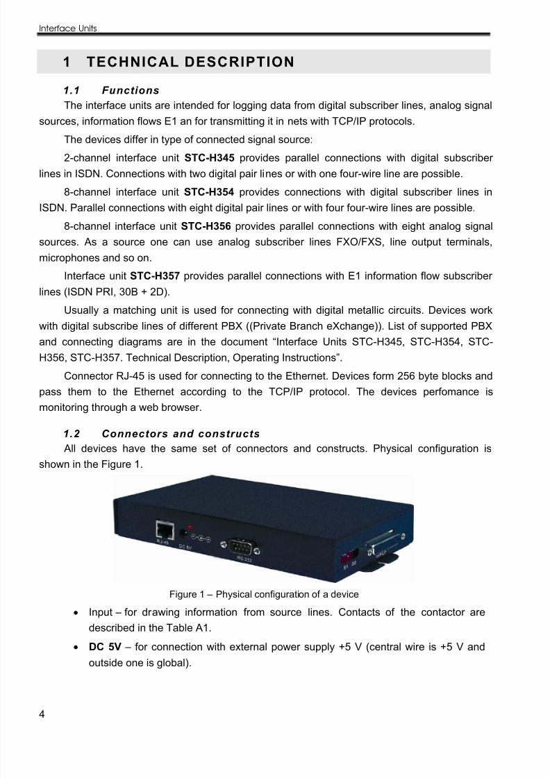
1.2 Connectors and constructsAll devices have the same set of connectors and constructs. Physical configuration is
shown in the Figure 1.
Figure 1 – Physical configuration of a device
Input – for drawing information from source lines. Contacts of the contactor aredescribed in the Table A1.
DC 5V – for connection with external power supply +5 V (central wire is +5 V andoutside one is global).
8/6/2019 H345, 354, 356, 357 UM eng
http://slidepdf.com/reader/full/h345-354-356-357-um-eng 5/20
Technical Description
5
RJ-45 – connector (8P8C) for connection with TCP\IP nets. Optional power supply(STC-H345, STC-H356, STC-H357) by PoE (Power over Ethernet) standard (IEEEStd.802.3af) or from the УАТС 48 В battery with any polarity is possible. Contacts of the contactor are described in the Table A2.
RS-232 – for connection with devices of controlled terminals (optional).
S1 and S2 – switches S1 and S2 set multiplication factor in the first and secondchannels correspondingly for digital subscriber lines. Switch positions for differenttypes of digital lines are shown in the Table B1. Dependence of the multiplicationfactor from switch position is shown in the Table B2.
Status light +5 V is at the DC 5V connector.
«Reset» button for return default net settings is on the case underside.
On the device case, there are keeper strips for bolting to a surface or installing to acabinet.
2 CONNECTIO NS TO SIGN AL SOURCES
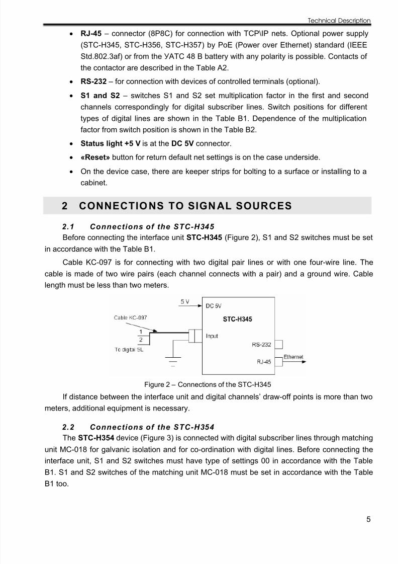
2.1 Connections of the STC-H345 Before connecting the interface unit STC-H345 (Figure 2), S1 and S2 switches must be set
in accordance with the Table B1.
Cable KC-097 is for connecting with two digital pair lines or with one four-wire line. Thecable is made of two wire pairs (each channel connects with a pair) and a ground wire. Cable
length must be less than two meters.
Figure 2 – Connections of the STC-H345
If distance between the interface unit and digital channels’ draw-off points is more than twometers, additional equipment is necessary.
2.2 Connections of the STC-H354The STC-H354 device (Figure 3) is connected with digital subscriber lines through matching
unit MC-018 for galvanic isolation and for co-ordination with digital lines. Before connecting theinterface unit, S1 and S2 switches must have type of settings 00 in accordance with the Table
B1. S1 and S2 switches of the matching unit MC-018 must be set in accordance with the TableB1 too.

8/6/2019 H345, 354, 356, 357 UM eng
http://slidepdf.com/reader/full/h345-354-356-357-um-eng 6/20
Interface Units
6
Figure 3 – Connections of the STC-Н354
Cable KM-017 connects MC-018 module with the device STC-H354. The base cable(twisted-pair) length is 5 meters and it could be lengthen up to 50 meters. If there is a need tolenghten cable up to 300 meters it is necessary to use another cable type (KM-035) and a side-mounted 5 V power supply unit for MC-018 module power supply.
Cable KC-034 connects with eight digital pair lines or with four four-wire lines. The cable ismade of eight wire pairs, each channel connects with a pair. Cable length must not be more thantwo meters.
Note. It is possible to use another types of matching units (MC-016, MC-006).
Attention! The STC-H354 device can get power supply only from 5 V power source.
2.3 Connections of the STC-H356 If the STC-H356 device is connected with analog signal sources only (telephone lines,
linear outputs and so on) the KC-037 cable is necessary for usage.For usage a microphone board with phantom 12 V power supply the KC-038 cable is
necessary (in pair, colored wire is PLUS and white one is MINUS).
For connection with eight analog and two digital pair lines the KC-036 cable is necessary.The cable is made of ten wire pairs, each channel connects with a pair. For digital channels,cable length must be less than two meters. Before connection with subscriber lines, S1 and S2switches must be set in accordance with the Table B1.
In the Figure 4 a variant of connecting the STC-H356 with 8 analog subscriber lines and 2
digital signal sources with no matching module is shown.
Figure 4 – The STC-H356 with 2 digital and 8 analog channels
8/6/2019 H345, 354, 356, 357 UM eng
http://slidepdf.com/reader/full/h345-354-356-357-um-eng 7/20
Technical Description
7
If distance between the interface unit and digital channels’ draw-off points is more than twometers, matching unit MC-006 and cables KC-039, KMC-003 are necessary. Before connectionwith subscriber lines, S1 and S2 switches must be set in accordance with the Table B1. S1 andS2 switches of the matching unit MC-018 must be set in accordance with the Table B1 demandsto type of the digital line.
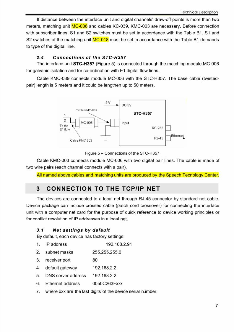
2.4 Connections of the STC-H357 The interface unit STC-H357 (Figure 5) is connected through the matching module MC-006
for galvanic isolation and for co-ordination with E1 digital flow lines.
Cable KMC-039 connects module MC-006 with the STC-H357. The base cable (twisted-pair) length is 5 meters and it could be lengthen up to 50 meters.
Figure 5 – Connections of the STC-Н357
Cable KMC-003 connects module MC-006 with two digital pair lines. The cable is made of
two wire pairs (each channel connects with a pair).All named above cables and matching units are produced by the Speech Tecnology Center.
3 CONNECTIO N TO THE TCP/IP NET
The devices are connected to a local net through RJ-45 connector by standard net cable.Device package can include crossed cable (patch cord crossover) for connecting the interfaceunit with a computer net card for the purpose of quick reference to device working principles or for conflict resolution of IP addresses in a local net.
3.1 Net set t ings by default By default, each device has factory settings:
1. IP address 192.168.2.91
2. subnet masks 255.255.255.0
3. receiver port 80
4. default gateway 192.168.2.2
5. DNS server address 192.168.2.2
6. Ethernet address 0050C263Fxxx
7. where xxx are the last digits of the device serial number.
8/6/2019 H345, 354, 356, 357 UM eng
http://slidepdf.com/reader/full/h345-354-356-357-um-eng 8/20
Interface Units
8
Default settings can be tuned. On the case underside, there is a Reset button for returndefault settings.
3.2 IP addresses conflict resolutionIf set by default IP address of the device conflicts with any other address in the net, net
parameters setting is necessary:
1. Connect the device with the computer directly.
2. Connect the device with the computer net card using crossed cable (patch cordcrossover).
3. In computer net card settings write IP address 192.168.2.1 and subnet mask255.255.255.0.
4. With the help of web browser get access to the device.
5. On the page of net settings write new IP address.
4 WORKING WITH THE DEVICE
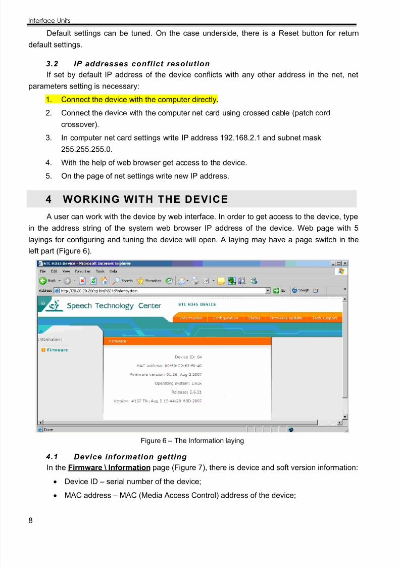
A user can work with the device by web interface. In order to get access to the device, typein the address string of the system web browser IP address of the device. Web page with 5layings for configuring and tuning the device will open. A laying may have a page switch in theleft part (Figure 6).
Figure 6 – The Information laying
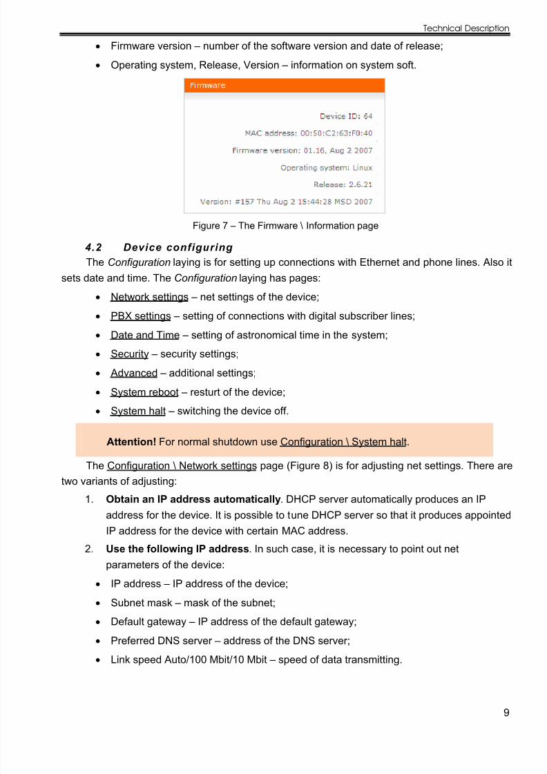
4.1 Device information getting In the Firmware \ Information page (Figure 7), there is device and soft version information:
Device ID – serial number of the device;
MAC address – MAC (Media Access Control) address of the device;
8/6/2019 H345, 354, 356, 357 UM eng
http://slidepdf.com/reader/full/h345-354-356-357-um-eng 9/20
Technical Description
9
Firmware version – number of the software version and date of release;
Operating system, Release, Version – information on system soft.
Figure 7 – The Firmware \ Information page
4.2 Device configuring
The Configuration laying is for setting up connections with Ethernet and phone lines. Also itsets date and time. The Configuration laying has pages:
Network settings – net settings of the device;
PBX settings – setting of connections with digital subscriber lines;
Date and Time – setting of astronomical time in the system;
Security – security settings;
Advanced – additional settings;
System reboot – resturt of the device;
System halt – switching the device off.
Attention! For normal shutdown use Configuration \ System halt.
The Configuration \ Network settings page (Figure 8) is for adjusting net settings. There aretwo variants of adjusting:
1. Obtain an IP address automatically . DHCP server automatically produces an IP
address for the device. It is possible to tune DHCP server so that it produces appointedIP address for the device with certain MAC address.
2. Use the following IP address . In such case, it is necessary to point out netparameters of the device:
IP address – IP address of the device;
Subnet mask – mask of the subnet;
Default gateway – IP address of the default gateway;
Preferred DNS server – address of the DNS server;
Link speed Auto/100 Mbit/10 Mbit – speed of data transmitting.
8/6/2019 H345, 354, 356, 357 UM eng
http://slidepdf.com/reader/full/h345-354-356-357-um-eng 10/20
Interface Units
10
Figure 8 – The Network settings page
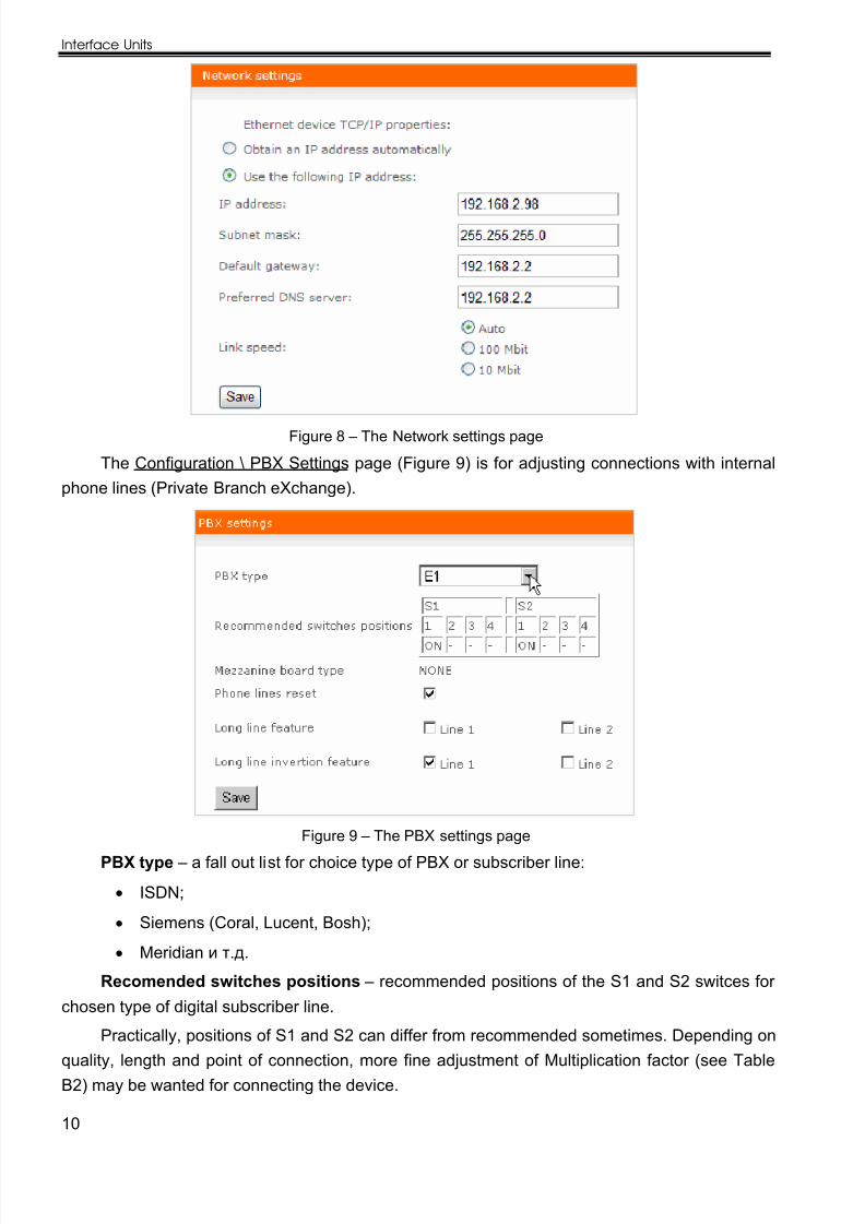
The Configuration \ PBX Settings page (Figure 9) is for adjusting connections with internalphone lines (Private Branch eXchange).
Figure 9 – The PBX settings page
PBX type – a fall out list for choice type of PBX or subscriber line:
ISDN;
Siemens (Coral, Lucent, Bosh);
Meridian и т.д.
Recomended switches positions – recommended positions of the S1 and S2 switces for
chosen type of digital subscriber line.
Practically, positions of S1 and S2 can differ from recommended sometimes. Depending onquality, length and point of connection, more fine adjustment of Multiplication factor (see TableB2) may be wanted for connecting the device.
8/6/2019 H345, 354, 356, 357 UM eng
http://slidepdf.com/reader/full/h345-354-356-357-um-eng 11/20
Technical Description
11
Mezzanine board type – type of installed additional board (The mezzanine is a subsidiaryboard mounted on the main board of the device. It is used for device enhancement – e.g. toincrease number of inputs from 2 to 8):
in the STC-H354, STC-H207 mezzanine is installed;
in the STC-H356, STC-H253 mezzanine is installed;
in the STC-H357, STC-H204 mezzanine is installed.
Phone lines reset – debugging parameter; it is recommended to switch it on in specialcases only.
Long line feature – feature of a long subscriber line. This mode is used if connection point
with a long line subscriber line is near the PBX. In this mode, the PBX signal is detecting at highthreshold value and signal of a telephone set is detecting at low threshold value. It is notrecommended to use the mode needlessly.
Long line invertion feature – feature of a long subscriber line invertion. This mode is usedif connecting point with a long subscriber line is situated in the neighbourhood with the telephoneset, far from the PBX. In this mode, the PBX signal is detecting at low threshold value and signalof a telephone set is detecting at high threshold value. Before switching to the mode, it isnecessary to switch on the Long line feature mode. It is not recommended to use the modeneedlessly.
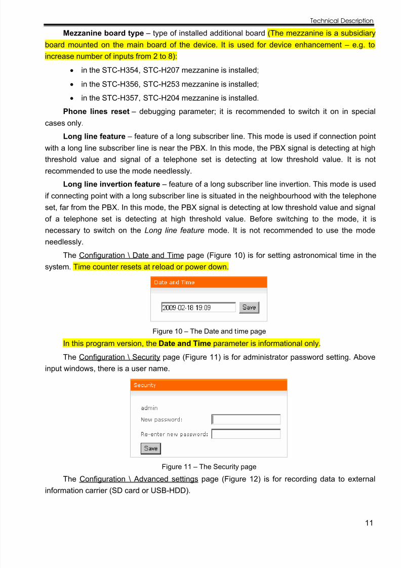
The Configuration \ Date and Time page (Figure 10) is for setting astronomical time in thesystem. Time counter resets at reload or power down.
Figure 10 – The Date and time page
In this program version, the Date and Time parameter is informational only.
The Configuration \ Security page (Figure 11) is for administrator password setting. Aboveinput windows, there is a user name.
Figure 11 – The Security page
The Configuration \ Advanced settings page (Figure 12) is for recording data to externalinformation carrier (SD card or USB-HDD).
8/6/2019 H345, 354, 356, 357 UM eng
http://slidepdf.com/reader/full/h345-354-356-357-um-eng 12/20
Interface Units
12
Figure 12 – The Advanced pageIn the current version, the Advanced page does not work.
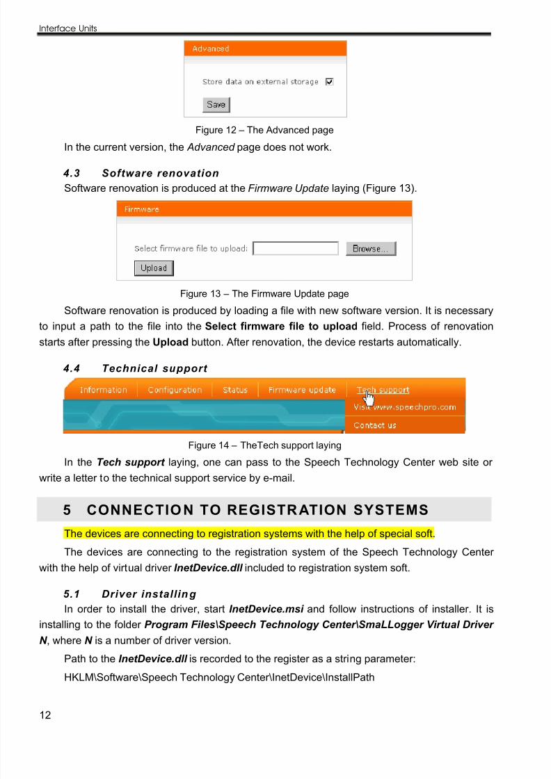
4.3 Software renovationSoftware renovation is produced at the Firmware Update laying (Figure 13).
Figure 13 – The Firmware Update page
Software renovation is produced by loading a file with new software version. It is necessaryto input a path to the file into the Select firmware file to upload field. Process of renovationstarts after pressing the Upload button. After renovation, the device restarts automatically.
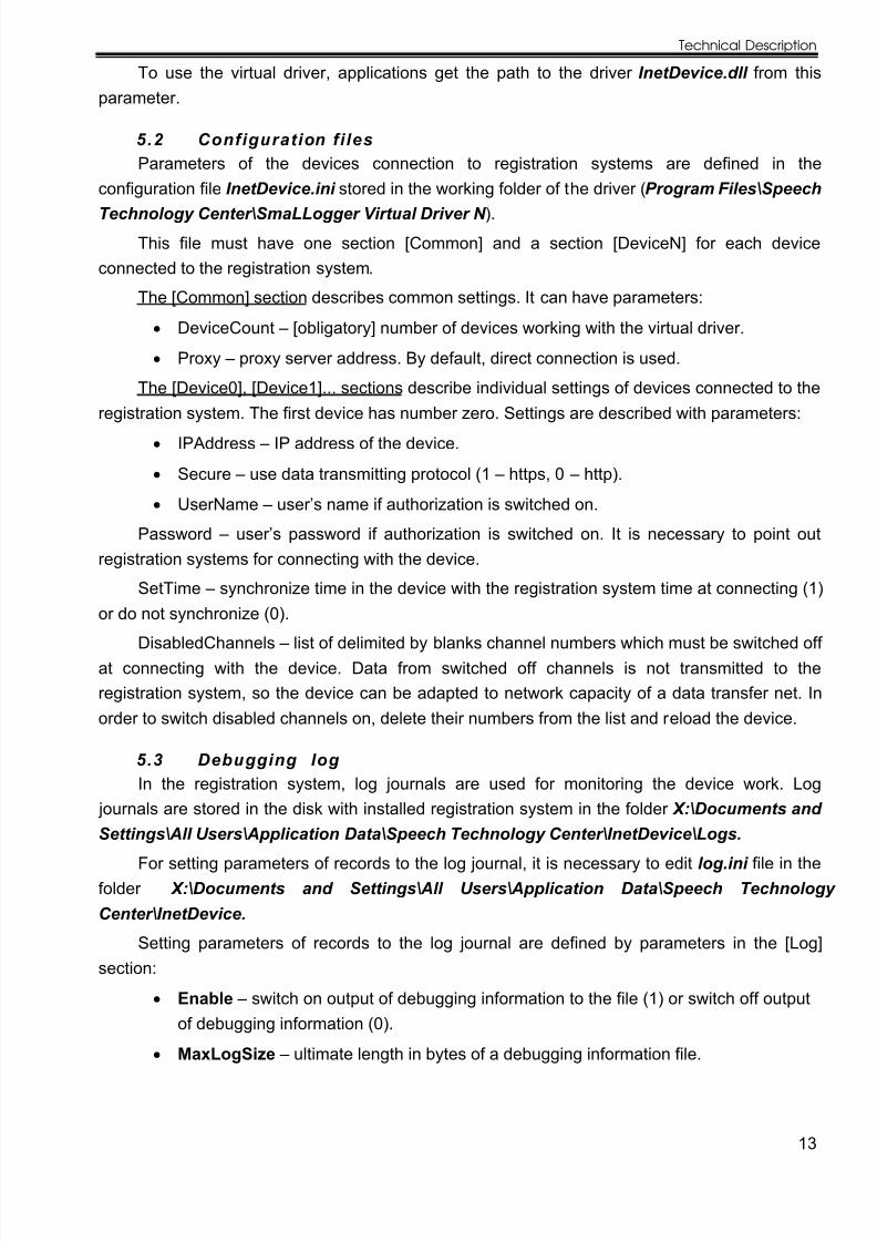
4.4 Technical support
Figure 14 – TheTech support laying
In the Tech support laying, one can pass to the Speech Technology Center web site or write a letter to the technical support service by e-mail.
5 CONNECTIO N TO REGISTR ATION SYSTEMS
The devices are connecting to registration systems with the help of special soft.
The devices are connecting to the registration system of the Speech Technology Center with the help of virtual driver InetDevice.dll included to registration system soft.
5.1 Driver installin g In order to install the driver, start InetDevice.msi and follow instructions of installer. It is
installing to the folder Program Files\Speech Technology Center\SmaLLogger Virtual Driver N , where N is a number of driver version.
Path to the InetDevice.dll is recorded to the register as a string parameter:
HKLM\Software\Speech Technology Center\InetDevice\InstallPath
8/6/2019 H345, 354, 356, 357 UM eng
http://slidepdf.com/reader/full/h345-354-356-357-um-eng 13/20
Technical Description
13
To use the virtual driver, applications get the path to the driver InetDevice.dll from thisparameter.
5.2 Configuration fi lesParameters of the devices connection to registration systems are defined in the
configuration file InetDevice.ini stored in the working folder of the driver ( Program Files\Speech
Technology Center\SmaLLogger Virtual Driver N ).
This file must have one section [Common] and a section [DeviceN] for each deviceconnected to the registration system.
The [Common] section describes common settings. It can have parameters:
DeviceCount – [obligatory] number of devices working with the virtual driver.
Proxy – proxy server address. By default, direct connection is used.
The [Device0], [Device1]... sections describe individual settings of devices connected to the
registration system. The first device has number zero. Settings are described with parameters:IPAddress – IP address of the device.
Secure – use data transmitting protocol (1 – https, 0 – http).
UserName – user’s name if authorization is switched on.
Password – user’s password if authorization is switched on. It is necessary to point outregistration systems for connecting with the device.
SetTime – synchronize time in the device with the registration system time at connecting (1)or do not synchronize (0).
DisabledChannels – list of delimited by blanks channel numbers which must be switched off at connecting with the device. Data from switched off channels is not transmitted to theregistration system, so the device can be adapted to network capacity of a data transfer net. Inorder to switch disabled channels on, delete their numbers from the list and reload the device.
5.3 Debugging log In the registration system, log journals are used for monitoring the device work. Log
journals are stored in the disk with installed registration system in the folder Х:\Documents and
Settings\All Users\Application Data\Speech Technology Center\InetDevice\Logs. For setting parameters of records to the log journal, it is necessary to edit log.ini file in the
folder X:\Documents and Settings\All Users\Application Data\Speech Technology Center\InetDevice.
Setting parameters of records to the log journal are defined by parameters in the [Log]section:
Enable – switch on output of debugging information to the file (1) or switch off outputof debugging information (0).
MaxLogSize – ultimate length in bytes of a debugging information file.

8/6/2019 H345, 354, 356, 357 UM eng
http://slidepdf.com/reader/full/h345-354-356-357-um-eng 14/20
Interface Units
14
MaxLogFiles – ultimate number of stored debugging information files. Cycle of writing is used. The oldest log journals are deleted.
5.4 Control of the record channelsAfter the device is started and authorized as a part of equipment in the registration system,
record channels of the device are controlled with GUI of the registration system (see descriptionof the used registration system).
8/6/2019 H345, 354, 356, 357 UM eng
http://slidepdf.com/reader/full/h345-354-356-357-um-eng 15/20
Technical Description
15
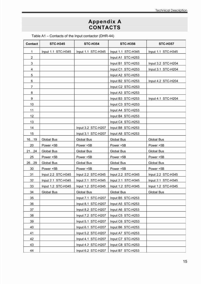
Appendix ACONTACTS
Table A1 – Contacts of the Input contactor (DHR-44)
Contact STC-Н345 STC-Н354 STC-Н356 STC-Н357
1 Input 1.1 STC-Н345 Input 1.1 STC-Н345 Input 1.1 STC-Н345 Input 1.1 STC-Н345
2 Input A1 STC-Н253
3 Input B1 STC-Н253 Input 3.2 STC-Н204
4 Input C1 STC-Н253 Input 3.1 STC-Н204
5 Input A2 STC-Н253
6 Input B2 STC-Н253 Input 4.2 STC-Н204
7 Input C2 STC-Н253
8 Input A3 STC-Н253
9 Input B3 STC-Н253 Input 4.1 STC-Н204
10 Input C3 STC-Н253
11 Input A4 STC-Н253
12 Input B4 STC-Н253
13 Input C4 STC-Н253
14 Input 3.2 STC-Н207 Input B8 STC-Н253
15 Input 3.1 STC-Н207 Input A8 STC-Н253
16…19 Global Bus Global Bus Global Bus Global Bus
20 Power +5В Power +5В Power +5В Power +5В
21…24 Global Bus Global Bus Global Bus Global Bus
25 Power +5В Power +5В Power +5В Power +5В
26…29 Global Bus Global Bus Global Bus Global Bus
30 Power +5В Power +5В Power +5В Power +5В
31 Input 2.2 STC-Н345 Input 2.2 STC-Н345 Input 2.2 STC-Н345 Input 2.2 STC-Н345
32 Input 2.1 STC-Н345 Input 2.1 STC-Н345 Input 2.1 STC-Н345 Input 2.1 STC-Н345
33 Input 1.2 STC-Н345 Input 1.2 STC-Н345 Input 1.2 STC-Н345 Input 1.2 STC-Н345
34 Global Bus Global Bus Global Bus Global Bus
35 Input 7.1 STC-Н207 Input B5 STC-Н253
36 Input 8.1 STC-Н207 Input A5 STC-Н253
37 Input 8.2 STC-Н207 Input A6 STC-Н253
38 Input 7.2 STC-Н207 Input C5 STC-Н253
39 Input 5.1 STC-Н207 Input C6 STC-Н253
40 Input 6.1 STC-Н207 Input B6 STC-Н253
41 Input 5.2 STC-Н207 Input A7 STC-Н253
42 Input 4.1 STC-Н207 Input C7 STC-Н253
43 Input 4.2 STC-Н207 Input C8 STC-Н253
44 Input 6.2 STC-Н207 Input B7 STC-Н253
8/6/2019 H345, 354, 356, 357 UM eng
http://slidepdf.com/reader/full/h345-354-356-357-um-eng 16/20
Interface Units
16
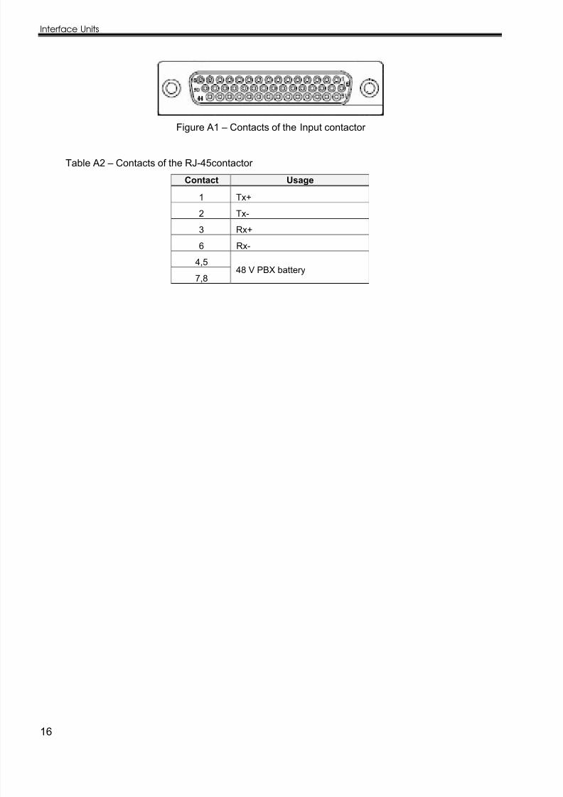
Figure A1 – Contacts of the Input contactor
Table A2 – Contacts of the RJ-45contactor
Contact Usage
1 Tx+
2 Tx-
3 Rx+
6 Rx-
4,5
7,848 V PBX battery
8/6/2019 H345, 354, 356, 357 UM eng
http://slidepdf.com/reader/full/h345-354-356-357-um-eng 17/20
Technical Description
17
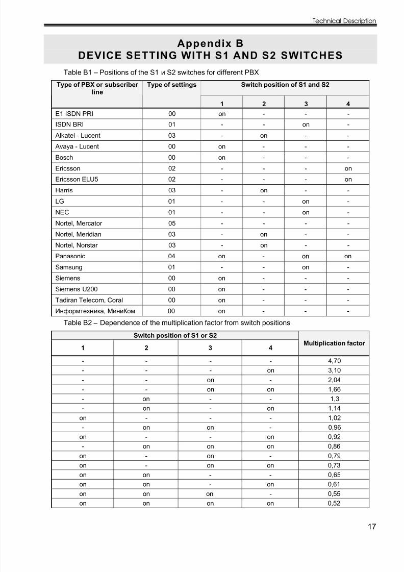
Appendix BDEVICE SETTING WITH S1 AND S2 SWITCHES
Table B1 – Positions of the S1 и S2 switches for different PBX
Switch position of S1 and S2Type of PBX or subscriber line
Type of settings
1 2 3 4E1 ISDN PRI 00 on - - -
ISDN BRI 01 - - on -
Alkatel - Lucent 03 - on - -
Avaya - Lucent 00 on - - -
Bosch 00 on - - -
Ericsson 02 - - - on
Ericsson ELU5 02 - - - on
Harris 03 - on - -LG 01 - - on -
NEC 01 - - on -
Nortel, Mercator 05 - - - -
Nortel, Meridian 03 - on - -
Nortel, Norstar 03 - on - -
Panasonic 04 on - on on
Samsung 01 - - on -
Siemens 00 on - - -
Siemens U200 00 on - - -
Tadiran Telecom, Coral 00 on - - -
Информтехника, МиниКом 00 on - - -
Table B2 – Dependence of the multiplication factor from switch positions
Switch position of S1 or S2
1 2 3 4Multiplication factor
- - - - 4,70- - - on 3,10- - on - 2,04- - on on 1,66- on - - 1,3- on - on 1,14
on - - - 1,02- on on - 0,96
on - - on 0,92- on on on 0,86
on - on - 0,79on - on on 0,73on on - - 0,65on on - on 0,61on on on - 0,55on on on on 0,52

8/6/2019 H345, 354, 356, 357 UM eng
http://slidepdf.com/reader/full/h345-354-356-357-um-eng 18/20
Interface Units
18
02-130309

8/6/2019 H345, 354, 356, 357 UM eng
http://slidepdf.com/reader/full/h345-354-356-357-um-eng 19/20

8/6/2019 H345, 354, 356, 357 UM eng
http://slidepdf.com/reader/full/h345-354-356-357-um-eng 20/20