fir REGULAMENTO BRASILEIRO DA AVIAÇÃO CIVIL
364
REGULAMENTO BRASILEIRO DA AVIAÇÃO CIVIL RBAC Nº 23 EMENDA Nº 62 Título: REQUISITOS DE AERONAVEGABILIDADE: AVIÕES CATEGORIA NORMAL, UTILIDADE, ACROBÁTICA E TRANSPORTE REGIONAL. Aprovação: Resolução nº 446, de 6 de setembro de 2017. Origem: SAR SUMÁRIO 23.00 Requisitos da adoção APÊNDICE A-I DO RBAC 23 – REPUBLICAÇÃO DO 14 CFR PART 23, EMENDA 23-62, ADOTADO PELO RBAC 23 23.00 Requisitos da adoção
Transcript of fir REGULAMENTO BRASILEIRO DA AVIAÇÃO CIVIL
fir
REGULAMENTO BRASILEIRO
DA AVIAÇÃO CIVIL RBAC Nº 23
EMENDA Nº 62
Título: REQUISITOS DE AERONAVEGABILIDADE:
AVIÕES CATEGORIA NORMAL, UTILIDADE,
ACROBÁTICA E TRANSPORTE REGIONAL. Aprovação: Resolução nº 446, de 6 de setembro de 2017. Origem: SAR
SUMÁRIO
23.00 Requisitos da adoção
APÊNDICE A-I DO RBAC 23 – REPUBLICAÇÃO DO 14 CFR PART 23, EMENDA 23-62,
ADOTADO PELO RBAC 23
23.00 Requisitos da adoção
Data da emissão: 11 de setembro de 2017 RBAC nº 23
Emenda nº 62
Origem: SAR 2/364
(a) Geral
Para concessão de certificados de tipo para aviões categoria normal, utilidade, acrobática e trans-
porte regional, será adotado integralmente, na língua inglesa, o regulamento Title 14 Code of
Federal Regulations Part 23, Emenda 23-62, efetiva em 31 de janeiro de 2012, da autoridade
de aviação civil, Federal Aviation Administration – FAA, do Department of Transportation
dos Estados Unidos da América, o qual é republicado no Apêndice A-I deste RBAC a partir do
contido no sítio de publicação do regulamento adotado em pauta: https://www.ecfr. gov.
(b) Divergência editorial
Qualquer divergência editorial contida no Apêndice A-I decorrente da republicação ali contida e
o texto oficial da FAA deverá prevalecer, mediante anuência da ANAC, o texto oficial da FAA.
(c) Republicação
Sempre que houver emenda no regulamento 14 Code of Federal Regulations Part 23, a ANAC
republicará o texto do regulamento adotado na forma do Apêndice A-I, por meio de emendas a
este RBAC.
(d) Emenda deste RBAC
Especificamente para este RBAC a indicação de sua emenda também é através da adoção da
emenda do regulamento adotado e republicado no Apêndice A-I deste RBAC, portanto seguindo
a indicação da emenda do regulamento adotado e indicado no parágrafo (a) desta seção.
APÊNDICE A-I DO RBAC 23
Data da emissão: 11 de setembro de 2017 RBAC nº 23
Emenda nº 62
Origem: SAR 3/364
REPUBLICAÇÃO DO 14 CFR PART 23, EMENDA 23-62, ADOTADO PELO RBAC 23
Title 14: Aeronautics and Space
PART 23—AIRWORTHINESS STANDARDS: NORMAL, UTILITY, ACROBATIC, AND
COMMUTER CATEGORY AIRPLANES
Special Federal Aviation Regulation No. 23
Subpart A—General
§ 23.1 Applicability.
§ 23.2 Special retroactive requirements.
§ 23.3 Airplane categories.
Subpart B—Flight
General
§ 23.21 Proof of compliance.
§ 23.23 Load distribution limits.
§ 23.25 Weight limits.
§ 23.29 Empty weight and corresponding center of gravity.
§ 23.31 Removable ballast.
§ 23.33 Propeller speed and pitch limits.
Performance
§ 23.45 General.
§ 23.49 Stalling speed.
§ 23.51 Takeoff speeds.
§ 23.53 Takeoff performance.
§ 23.55 Accelerate-stop distance.
§ 23.57 Takeoff path.
§ 23.59 Takeoff distance and takeoff run.
§ 23.61 Takeoff flight path.
§ 23.63 Climb: General.
§ 23.65 Climb: All engines operating.
§ 23.66 Takeoff climb: One-engine inoperative.
§ 23.67 Climb: One engine inoperative.
§ 23.69 Enroute climb/descent.
§ 23.71 Glide: Single-engine airplanes.
§ 23.73 Reference landing approach speed.
§ 23.75 Landing distance.
§ 23.77 Balked landing.
Flight Characteristics
§ 23.141 General.
Controllability and Maneuverability
§ 23.143 General.
§ 23.145 Longitudinal control.
§ 23.147 Directional and lateral control.

Data da emissão: 11 de setembro de 2017 RBAC nº 23
Emenda nº 62
Origem: SAR 4/364
§ 23.149 Minimum control speed.
§ 23.151 Acrobatic maneuvers.
§ 23.153 Control during landings.
§ 23.155 Elevator control force in maneuvers.
§ 23.157 Rate of roll.
Trim
§ 23.161 Trim.
Stability
§ 23.171 General.
§ 23.173 Static longitudinal stability.
§ 23.175 Demonstration of static longitudinal stability.
§ 23.177 Static directional and lateral stability.
§ 23.181 Dynamic stability.
Stalls
§ 23.201 Wings level stall.
§ 23.203 Turning flight and accelerated turning stalls.
§ 23.207 Stall warning.
Spinning
§ 23.221 Spinning.
Ground and Water Handling Characteristics
§ 23.231 Longitudinal stability and control.
§ 23.233 Directional stability and control.
§ 23.235 Operation on unpaved surfaces.
§ 23.237 Operation on water.
§ 23.239 Spray characteristics.
Miscellaneous Flight Requirements
§ 23.251 Vibration and buffeting.
§ 23.253 High speed characteristics.
§ 23.255 Out of trim characteristics.
Subpart C—Structure
General
§ 23.301 Loads.
§ 23.302 Canard or tandem wing configurations.
§ 23.303 Factor of safety.
§ 23.305 Strength and deformation.
§ 23.307 Proof of structure.
Flight Loads
§ 23.321 General.
§ 23.331 Symmetrical flight conditions.
§ 23.333 Flight envelope.

Data da emissão: 11 de setembro de 2017 RBAC nº 23
Emenda nº 62
Origem: SAR 5/364
§ 23.335 Design airspeeds.
§ 23.337 Limit maneuvering load factors.
§ 23.341 Gust loads factors.
§ 23.343 Design fuel loads.
§ 23.345 High lift devices.
§ 23.347 Unsymmetrical flight conditions.
§ 23.349 Rolling conditions.
§ 23.351 Yawing conditions.
§ 23.361 Engine torque.
§ 23.363 Side load on engine mount.
§ 23.365 Pressurized cabin loads.
§ 23.367 Unsymmetrical loads due to engine failure.
§ 23.369 Rear lift truss.
§ 23.371 Gyroscopic and aerodynamic loads.
§ 23.373 Speed control devices.
Control Surface and System Loads
§ 23.391 Control surface loads.
§ 23.393 Loads parallel to hinge line.
§ 23.395 Control system loads.
§ 23.397 Limit control forces and torques.
§ 23.399 Dual control system.
§ 23.405 Secondary control system.
§ 23.407 Trim tab effects.
§ 23.409 Tabs.
§ 23.415 Ground gust conditions.
Horizontal Stabilizing and Balancing Surfaces
§ 23.421 Balancing loads.
§ 23.423 Maneuvering loads.
§ 23.425 Gust loads.
§ 23.427 Unsymmetrical loads.
Vertical Surfaces
§ 23.441 Maneuvering loads.
§ 23.443 Gust loads.
§ 23.445 Outboard fins or winglets.
Ailerons and Special Devices
§ 23.455 Ailerons.
§ 23.459 Special devices.
Ground Loads
§ 23.471 General.
§ 23.473 Ground load conditions and assumptions.
§ 23.477 Landing gear arrangement.
§ 23.479 Level landing conditions.
§ 23.481 Tail down landing conditions.
§ 23.483 One-wheel landing conditions.
§ 23.485 Side load conditions.

Data da emissão: 11 de setembro de 2017 RBAC nº 23
Emenda nº 62
Origem: SAR 6/364
§ 23.493 Braked roll conditions.
§ 23.497 Supplementary conditions for tail wheels.
§ 23.499 Supplementary conditions for nose wheels.
§ 23.505 Supplementary conditions for skiplanes.
§ 23.507 Jacking loads.
§ 23.509 Towing loads.
§ 23.511 Ground load; unsymmetrical loads on multiple-wheel units.
Water Loads
§ 23.521 Water load conditions.
§ 23.523 Design weights and center of gravity positions.
§ 23.525 Application of loads.
§ 23.527 Hull and main float load factors.
§ 23.529 Hull and main float landing conditions.
§ 23.531 Hull and main float takeoff condition.
§ 23.533 Hull and main float bottom pressures.
§ 23.535 Auxiliary float loads.
§ 23.537 Seawing loads.
Emergency Landing Conditions
§ 23.561 General.
§ 23.562 Emergency landing dynamic conditions.
Fatigue Evaluation
§ 23.571 Metallic pressurized cabin structures.
§ 23.572 Metallic wing, empennage, and associated structures.
§ 23.573 Damage tolerance and fatigue evaluation of structure.
§ 23.574 Metallic damage tolerance and fatigue evaluation of commuter category airplanes.
§ 23.575 Inspections and other procedures.
Subpart D—Design and Construction
§ 23.601 General.
§ 23.603 Materials and workmanship.
§ 23.605 Fabrication methods.
§ 23.607 Fasteners.
§ 23.609 Protection of structure.
§ 23.611 Accessibility provisions.
§ 23.613 Material strength properties and design values.
§ 23.619 Special factors.
§ 23.621 Casting factors.
§ 23.623 Bearing factors.
§ 23.625 Fitting factors.
§ 23.627 Fatigue strength.
§ 23.629 Flutter.
Wings
§ 23.641 Proof of strength.
Control Surfaces
§ 23.651 Proof of strength.

Data da emissão: 11 de setembro de 2017 RBAC nº 23
Emenda nº 62
Origem: SAR 7/364
§ 23.655 Installation.
§ 23.657 Hinges.
§ 23.659 Mass balance.
Control Systems
§ 23.671 General.
§ 23.672 Stability augmentation and automatic and power-operated systems.
§ 23.673 Primary flight controls.
§ 23.675 Stops.
§ 23.677 Trim systems.
§ 23.679 Control system locks.
§ 23.681 Limit load static tests.
§ 23.683 Operation tests.
§ 23.685 Control system details.
§ 23.687 Spring devices.
§ 23.689 Cable systems.
§ 23.691 Artificial stall barrier system.
§ 23.693 Joints.
§ 23.697 Wing flap controls.
§ 23.699 Wing flap position indicator.
§ 23.701 Flap interconnection.
§ 23.703 Takeoff warning system.
Landing Gear
§ 23.721 General.
§ 23.723 Shock absorption tests.
§ 23.725 Limit drop tests.
§ 23.726 Ground load dynamic tests.
§ 23.727 Reserve energy absorption drop test.
§ 23.729 Landing gear extension and retraction system.
§ 23.731 Wheels.
§ 23.733 Tires.
§ 23.735 Brakes.
§ 23.737 Skis.
§ 23.745 Nose/tail wheel steering.
Floats and Hulls
§ 23.751 Main float buoyancy.
§ 23.753 Main float design.
§ 23.755 Hulls.
§ 23.757 Auxiliary floats.
Personnel and Cargo Accommodations
§ 23.771 Pilot compartment.
§ 23.773 Pilot compartment view.
§ 23.775 Windshields and windows.
§ 23.777 Cockpit controls.
§ 23.779 Motion and effect of cockpit controls.
§ 23.781 Cockpit control knob shape.
§ 23.783 Doors.

Data da emissão: 11 de setembro de 2017 RBAC nº 23
Emenda nº 62
Origem: SAR 8/364
§ 23.785 Seats, berths, litters, safety belts, and shoulder harnesses.
§ 23.787 Baggage and cargo compartments.
§ 23.791 Passenger information signs.
§ 23.803 Emergency evacuation.
§ 23.805 Flightcrew emergency exits.
§ 23.807 Emergency exits.
§ 23.811 Emergency exit marking.
§ 23.812 Emergency lighting.
§ 23.813 Emergency exit access.
§ 23.815 Width of aisle.
§ 23.831 Ventilation.
Pressurization
§ 23.841 Pressurized cabins.
§ 23.843 Pressurization tests.
Fire Protection
§ 23.851 Fire extinguishers.
§ 23.853 Passenger and crew compartment interiors.
§ 23.855 Cargo and baggage compartment fire protection.
§ 23.856 Thermal/acoustic insulation materials.
§ 23.859 Combustion heater fire protection.
§ 23.863 Flammable fluid fire protection.
§ 23.865 Fire protection of flight controls, engine mounts, and other flight structure.
Electrical Bonding and Lightning Protection
§ 23.867 Electrical bonding and protection against lightning and static electricity.
Miscellaneous
§ 23.871 Leveling means.
Subpart E—Powerplant
General
§ 23.901 Installation.
§ 23.903 Engines.
§ 23.904 Automatic power reserve system.
§ 23.905 Propellers.
§ 23.907 Propeller vibration and fatigue.
§ 23.909 Turbocharger systems.
§ 23.925 Propeller clearance.
§ 23.929 Engine installation ice protection.
§ 23.933 Reversing systems.
§ 23.934 Turbojet and turbofan engine thrust reverser systems tests.
§ 23.937 Turbopropeller-drag limiting systems.
§ 23.939 Powerplant operating characteristics.
§ 23.943 Negative acceleration.
Fuel System
§ 23.951 General.
§ 23.953 Fuel system independence.
§ 23.954 Fuel system lightning protection.

Data da emissão: 11 de setembro de 2017 RBAC nº 23
Emenda nº 62
Origem: SAR 9/364
§ 23.955 Fuel flow.
§ 23.957 Flow between interconnected tanks.
§ 23.959 Unusable fuel supply.
§ 23.961 Fuel system hot weather operation.
§ 23.963 Fuel tanks: General.
§ 23.965 Fuel tank tests.
§ 23.967 Fuel tank installation.
§ 23.969 Fuel tank expansion space.
§ 23.971 Fuel tank sump.
§ 23.973 Fuel tank filler connection.
§ 23.975 Fuel tank vents and carburetor vapor vents.
§ 23.977 Fuel tank outlet.
§ 23.979 Pressure fueling systems.
Fuel System Components
§ 23.991 Fuel pumps.
§ 23.993 Fuel system lines and fittings.
§ 23.994 Fuel system components.
§ 23.995 Fuel valves and controls.
§ 23.997 Fuel strainer or filter.
§ 23.999 Fuel system drains.
§ 23.1001 Fuel jettisoning system.
Oil System
§ 23.1011 General.
§ 23.1013 Oil tanks.
§ 23.1015 Oil tank tests.
§ 23.1017 Oil lines and fittings.
§ 23.1019 Oil strainer or filter.
§ 23.1021 Oil system drains.
§ 23.1023 Oil radiators.
§ 23.1027 Propeller feathering system.
Cooling
§ 23.1041 General.
§ 23.1043 Cooling tests.
§ 23.1045 Cooling test procedures for turbine engine powered airplanes.
§ 23.1047 Cooling test procedures for reciprocating engine powered airplanes.
Liquid Cooling
§ 23.1061 Installation.
§ 23.1063 Coolant tank tests.
Induction System
§ 23.1091 Air induction system.
§ 23.1093 Induction system icing protection.
§ 23.1095 Carburetor deicing fluid flow rate.
§ 23.1097 Carburetor deicing fluid system capacity.
§ 23.1099 Carburetor deicing fluid system detail design.
§ 23.1101 Induction air preheater design.
Data da emissão: 11 de setembro de 2017 RBAC nº 23
Emenda nº 62
Origem: SAR 10/364
§ 23.1103 Induction system ducts.
§ 23.1105 Induction system screens.
§ 23.1107 Induction system filters.
§ 23.1109 Turbocharger bleed air system.
§ 23.1111 Turbine engine bleed air system.
Exhaust System
§ 23.1121 General.
§ 23.1123 Exhaust system.
§ 23.1125 Exhaust heat exchangers.
Powerplant Controls and Accessories
§ 23.1141 Powerplant controls: General.
§ 23.1142 Auxiliary power unit controls.
§ 23.1143 Engine controls.
§ 23.1145 Ignition switches.
§ 23.1147 Mixture controls.
§ 23.1149 Propeller speed and pitch controls.
§ 23.1153 Propeller feathering controls.
§ 23.1155 Turbine engine reverse thrust and propeller pitch settings below the flight regime.
§ 23.1157 Carburetor air temperature controls.
§ 23.1163 Powerplant accessories.
§ 23.1165 Engine ignition systems.
Powerplant Fire Protection
§ 23.1181 Designated fire zones; regions included.
§ 23.1182 Nacelle areas behind firewalls.
§ 23.1183 Lines, fittings, and components.
§ 23.1189 Shutoff means.
§ 23.1191 Firewalls.
§ 23.1192 Engine accessory compartment diaphragm.
§ 23.1193 Cowling and nacelle.
§ 23.1195 Fire extinguishing systems.
§ 23.1197 Fire extinguishing agents.
§ 23.1199 Extinguishing agent containers.
§ 23.1201 Fire extinguishing systems materials.
§ 23.1203 Fire detector system.
Subpart F—Equipment
General
§ 23.1301 Function and installation.
§ 23.1303 Flight and navigation instruments.
§ 23.1305 Powerplant instruments.
§ 23.1306 Electrical and electronic system lightning protection.
§ 23.1307 Miscellaneous equipment.
§ 23.1308 High-intensity Radiated Fields (HIRF) Protection.
§ 23.1309 Equipment, systems, and installations.
§ 23.1310 Power source capacity and distribution.
Instruments: Installation

Data da emissão: 11 de setembro de 2017 RBAC nº 23
Emenda nº 62
Origem: SAR 11/364
§ 23.1311 Electronic display instrument systems.
§ 23.1321 Arrangement and visibility.
§ 23.1322 Warning, caution, and advisory lights.
§ 23.1323 Airspeed indicating system.
§ 23.1325 Static pressure system.
§ 23.1326 Pitot heat indication systems.
§ 23.1327 Magnetic direction indicator.
§ 23.1329 Automatic pilot system.
§ 23.1331 Instruments using a power source.
§ 23.1335 Flight director systems.
§ 23.1337 Powerplant instruments installation.
Electrical Systems and Equipment
§ 23.1351 General.
§ 23.1353 Storage battery design and installation.
§ 23.1357 Circuit protective devices.
§ 23.1359 Electrical system fire protection.
§ 23.1361 Master switch arrangement.
§ 23.1365 Electric cables and equipment.
§ 23.1367 Switches.
Lights
§ 23.1381 Instrument lights.
§ 23.1383 Taxi and landing lights.
§ 23.1385 Position light system installation.
§ 23.1387 Position light system dihedral angles.
§ 23.1389 Position light distribution and intensities.
§ 23.1391 Minimum intensities in the horizontal plane of position lights.
§ 23.1393 Minimum intensities in any vertical plane of position lights.
§ 23.1395 Maximum intensities in overlapping beams of position lights.
§ 23.1397 Color specifications.
§ 23.1399 Riding light.
§ 23.1401 Anticollision light system.
Safety Equipment
§ 23.1411 General.
§ 23.1415 Ditching equipment.
§ 23.1416 Pneumatic de-icer boot system.
§ 23.1419 Ice protection.
Miscellaneous Equipment
§ 23.1431 Electronic equipment.
§ 23.1435 Hydraulic systems.
§ 23.1437 Accessories for multiengine airplanes.
§ 23.1438 Pressurization and pneumatic systems.
§ 23.1441 Oxygen equipment and supply.
§ 23.1443 Minimum mass flow of supplemental oxygen.
§ 23.1445 Oxygen distribution system.
§ 23.1447 Equipment standards for oxygen dispensing units.
§ 23.1449 Means for determining use of oxygen.

Data da emissão: 11 de setembro de 2017 RBAC nº 23
Emenda nº 62
Origem: SAR 12/364
§ 23.1450 Chemical oxygen generators.
§ 23.1451 Fire protection for oxygen equipment.
§ 23.1453 Protection of oxygen equipment from rupture.
§ 23.1457 Cockpit voice recorders.
§ 23.1459 Flight data recorders.
§ 23.1461 Equipment containing high energy rotors.
Subpart G—Operating Limitations and Information
§ 23.1501 General.
§ 23.1505 Airspeed limitations.
§ 23.1507 Operating maneuvering speed.
§ 23.1511 Flap extended speed.
§ 23.1513 Minimum control speed.
§ 23.1519 Weight and center of gravity.
§ 23.1521 Powerplant limitations.
§ 23.1522 Auxiliary power unit limitations.
§ 23.1523 Minimum flight crew.
§ 23.1524 Maximum passenger seating configuration.
§ 23.1525 Kinds of operation.
§ 23.1527 Maximum operating altitude.
§ 23.1529 Instructions for Continued Airworthiness.
Markings And Placards
§ 23.1541 General.
§ 23.1543 Instrument markings: General.
§ 23.1545 Airspeed indicator.
§ 23.1547 Magnetic direction indicator.
§ 23.1549 Powerplant and auxiliary power unit instruments.
§ 23.1551 Oil quantity indicator.
§ 23.1553 Fuel quantity indicator.
§ 23.1555 Control markings.
§ 23.1557 Miscellaneous markings and placards.
§ 23.1559 Operating limitations placard.
§ 23.1561 Safety equipment.
§ 23.1563 Airspeed placards.
§ 23.1567 Flight maneuver placard.
Airplane Flight Manual and Approved Manual Material
§ 23.1581 General.
§ 23.1583 Operating limitations.
§ 23.1585 Operating procedures.
§ 23.1587 Performance information.
§ 23.1589 Loading information.
Appendix A to Part 23—Simplified Design Load Criteria
Appendix B to Part 23 [Reserved]
Appendix C to Part 23—Basic Landing Conditions
Appendix D to Part 23—Wheel Spin-Up and Spring-Back Loads
Appendix E to Part 23 [Reserved]
Appendix F to Part 23—Test Procedure
Appendix G to Part 23—Instructions for Continued Airworthiness

Data da emissão: 11 de setembro de 2017 RBAC nº 23
Emenda nº 62
Origem: SAR 13/364
Appendix H to Part 23—Installation of An Automatic Power Reserve (APR) System
Appendix I to Part 23—Seaplane Loads
Appendix J to Part 23—HIRF Environments and Equipment HIRF Test Levels
Authority: 49 U.S.C. 106(g), 40113, 44701–44702, 44704.
Source: Docket No. 4080, 29 FR 17955, Dec. 18. 1964; 30 FR 258, Jan. 9, 1965, unless otherwise
noted.
Special Federal Aviation Regulation No. 23
1. Applicability. An applicant is entitled to a type certificate in the normal category for a
reciprocating or turbopropeller multiengine powered small airplane that is to be certificated to carry
more than 10 occupants and that is intended for use in operations under Part 135 of the Federal
Aviation Regulations if he shows compliance with the applicable requirements of Part 23 of the
Federal Aviation Regulations, as supplemented or modified by the additional airworthiness
requirements of this regulation.
2. References. Unless otherwise provided, all references in this regulation to specific sections of
Part 23 of the Federal Aviation Regulations are those sections of Part 23 in effect on March 30,
1967.
Flight Requirements
3. General. Compliance must be shown with the applicable requirements of Subpart B of Part 23 of
the Federal Aviation Regulations in effect on March 30, 1967, as supplemented or modified in
sections 4 through 10 of this regulation.
Performance
4. General. (a) Unless otherwise prescribed in this regulation, compliance with each applicable
performance requirement in sections 4 through 7 of this regulation must be shown for ambient
atmospheric conditions and still air.
(b) The performance must correspond to the propulsive thrust available under the particular ambient
atmospheric conditions and the particular flight condition. The available propulsive thrust must
correspond to engine power or thrust, not exceeding the approved power or thrust less—
(1) Installation losses; and
(2) The power or equivalent thrust absorbed by the accessories and services appropriate to the
particular ambient atmospheric conditions and the particular flight condition.
(c) Unless otherwise prescribed in this regulation, the applicant must select the take-off, en route,
and landing configurations for the airplane.
(d) The airplane configuration may vary with weight, altitude, and temperature, to the extent they
are compatible with the operating procedures required by paragraph (e) of this section.
(e) Unless otherwise prescribed in this regulation, in determining the critical engine inoperative

Data da emissão: 11 de setembro de 2017 RBAC nº 23
Emenda nº 62
Origem: SAR 14/364
takeoff performance, the accelerate-stop distance, takeoff distance, changes in the airplane's
configuration, speed, power, and thrust, must be made in accordance with procedures established by
the applicant for operation in service.
(f) Procedures for the execution of balked landings must be established by the applicant and
included in the Airplane Flight Manual.
(g) The procedures established under paragraphs (e) and (f) of this section must—
(1) Be able to be consistently executed in service by a crew of average skill;
(2) Use methods or devices that are safe and reliable; and
(3) Include allowance for any time delays, in the execution of the procedures, that may reasonably
be expected in service.
5. Takeoff —(a) General. The takeoff speeds described in paragraph (b), the accelerate-stop
distance described in paragraph (c), and the takeoff distance described in paragraph (d), must be
determined for—
(1) Each weight, altitude, and ambient temperature within the operational limits selected by the
applicant;
(2) The selected configuration for takeoff;
(3) The center of gravity in the most unfavorable position;
(4) The operating engine within approved operating limitation; and
(5) Takeoff data based on smooth, dry, hard-surface runway.
(b) Takeoff speeds. (1) The decision speed V1 is the calibrated airspeed on the ground at which, as a
result of engine failure or other reasons, the pilot is assumed to have made a decision to continue or
discontinue the takeoff. The speed V1 must be selected by the applicant but may not be less than—
(i) 1.10 Vs1;
(ii) 1.10 V MC;
(iii) A speed that permits acceleration to V1 and stop in accordance with paragraph (c) allowing
credit for an overrun distance equal to that required to stop the airplane from a ground speed of 35
knots utilizing maximum braking; or
(iv) A speed at which the airplane can be rotated for takeoff and shown to be adequate to safely
continue the takeoff, using normal piloting skill, when the critical engine is suddenly made
inoperative.
(2) Other essential takeoff speeds necessary for safe operation of the airplane must be determined
and shown in the Airplane Flight Manual.
Data da emissão: 11 de setembro de 2017 RBAC nº 23
Emenda nº 62
Origem: SAR 15/364
(c) Accelerate-stop distance. (1) The accelerate-stop distance is the sum of the distances necessary
to—
(i) Accelerate the airplane from a standing start to V1; and
(ii) Decelerate the airplane from V1 to a speed not greater than 35 knots, assuming that in the case
of engine failure, failure of the critical engine is recognized by the pilot at the speed V1. The landing
gear must remain in the extended position and maximum braking may be utilized during
deceleration.
(2) Means other than wheel brakes may be used to determine the accelerate-stop distance if that
means is available with the critical engine inoperative and—
(i) Is safe and reliable;
(ii) Is used so that consistent results can be expected under normal operating conditions; and
(iii) Is such that exceptional skill is not required to control the airplane.
(d) All engines operating takeoff distance. The all engine operating takeoff distance is the
horizontal distance required to takeoff and climb to a height of 50 feet above the takeoff surface
according to procedures in FAR 23.51(a).
(e) One-engine-inoperative takeoff. The maximum weight must be determined for each altitude and
temperature within the operational limits established for the airplane, at which the airplane has
takeoff capability after failure of the critical engine at or above V 1 determined in accordance with
paragraph (b) of this section. This capability may be established—
(1) By demonstrating a measurably positive rate of climb with the airplane in the takeoff
configuration, landing gear extended; or
(2) By demonstrating the capability of maintaining flight after engine failure utilizing procedures
prescribed by the applicant.
6. Climb —(a) Landing climb: All-engines-operating. The maximum weight must be determined
with the airplane in the landing configuration, for each altitude, and ambient temperature within the
operational limits established for the airplane and with the most unfavorable center of gravity and
out-of-ground effect in free air, at which the steady gradient of climb will not be less than 3.3
percent, with:
(1) The engines at the power that is available 8 seconds after initiation of movement of the power or
thrust controls from the mimimum flight idle to the takeoff position.
(2) A climb speed not greater than the approach speed established under section 7 of this regulation
and not less than the greater of 1.05 MC or 1.10VS1.
(b) En route climb, one-engine-inoperative. (1) the maximum weight must be determined with the
airplane in the en route configuration, the critical engine inoperative, the remaining engine at not
more than maximum continuous power or thrust, and the most unfavorable center of gravity, at
Data da emissão: 11 de setembro de 2017 RBAC nº 23
Emenda nº 62
Origem: SAR 16/364
which the gradient at climb will be not less than—
(i) 1.2 percent (or a gradient equivalent to 0.20 Vso2, if greater) at 5,000 feet and an ambient
temperature of 41 °F. or
(ii) 0.6 percent (or a gradient equivalent to 0.01 Vso2, if greater) at 5,000 feet and ambient
temperature of 81 °F.
(2) The minimum climb gradient specified in subdivisions (i) and (ii) of subparagraph (1) of this
paragraph must vary linearly between 41 °F. and 81 °F. and must change at the same rate up to the
maximum operational temperature approved for the airplane.
7. Landing. The landing distance must be determined for standard atmosphere at each weight and
altitude in accordance with FAR 23.75(a), except that instead of the gliding approach specified in
FAR 23.75(a)(1), the landing may be preceded by a steady approach down to the 50-foot height at a
gradient of descent not greater than 5.2 percent (3°) at a calibrated airspeed not less than 1.3s1.
Trim
8. Trim —(a) Lateral and directional trim. The airplane must maintain lateral and directional trim in
level flight at a speed of Vh or VMO/ MMO,whichever is lower, with landing gear and wing flaps
retracted.
(b) Longitudinal trim. The airplane must maintain longitudinal trim during the following conditions,
except that it need not maintain trim at a speed greater than VMO/ MMO:
(1) In the approach conditions specified in FAR 23.161(c)(3) through (5), except that instead of the
speeds specified therein, trim must be maintained with a stick force of not more than 10 pounds
down to a speed used in showing compliance with section 7 of this regulation or 1.4 V s1whichever
is lower.
(2) In level flight at any speed from VH or VMO/ MMO, whichever is lower, to either Vx or 1.4 V s1,
with the landing gear and wing flaps retracted.
Stability
9. Static longitudinal stability. (a) In showing compliance with the provisions of FAR 23.175(b) and
with paragraph (b) of this section, the airspeed must return to within ±71/2percent of the trim speed.
(b) Cruise stability. The stick force curve must have a stable slope for a speed range of ±50 knots
from the trim speed except that the speeds need not exceed VFC/ MFC or be less than 1.4 V s1. This
speed range will be considered to begin at the outer extremes of the friction band and the stick force
may not exceed 50 pounds with—
(i) Landing gear retracted;
(ii) Wing flaps retracted;
(iii) The maximum cruising power as selected by the applicant as an operating limitation for turbine
Data da emissão: 11 de setembro de 2017 RBAC nº 23
Emenda nº 62
Origem: SAR 17/364
engines or 75 percent of maximum continuous power for reciprocating engines except that the
power need not exceed that required at VMO/ MMO:
(iv) Maximum takeoff weight; and
(v) The airplane trimmed for level flight with the power specified in subparagraph (iii) of this
paragraph.
VFC/ MFC may not be less than a speed midway between VMO/ MMO and VDF/ MDF, except that, for
altitudes where Mach number is the limiting factor, MFC need not exceed the Mach number at
which effective speed warning occurs.
(c) Climb stability. For turbopropeller powered airplanes only. In showing compliance with FAR
23.175(a), an applicant must in lieu of the power specified in FAR 23.175(a)(4), use the maximum
power or thrust selected by the applicant as an operating limitation for use during climb at the best
rate of climb speed except that the speed need not be less than 1.4 V s1.
Stalls
10. Stall warning. If artificial stall warning is required to comply with the requirements of FAR
23.207, the warning device must give clearly distinguishable indications under expected conditions
of flight. The use of a visual warning device that requires the attention of the crew within the
cockpit is not acceptable by itself.
Control Systems
11. Electric trim tabs. The airplane must meet the requirements of FAR 23.677 and in addition it
must be shown that the airplane is safely controllable and that a pilot can perform all the maneuvers
and operations necessary to effect a safe landing following any probable electric trim tab runaway
which might be reasonably expected in service allowing for appropriate time delay after pilot
recognition of the runaway. This demonstration must be conducted at the critical airplane weights
and center of gravity positions.
Instruments: Installation
12. Arrangement and visibility. Each instrument must meet the requirements of FAR 23.1321 and
in addition—
(a) Each flight, navigation, and powerplant instrument for use by any pilot must be plainly visible to
him from his station with the minimum practicable deviation from his normal position and line of
vision when he is looking forward along the flight path.
(b) The flight instruments required by FAR 23.1303 and by the applicable operating rules must be
grouped on the instrument panel and centered as nearly as practicable about the vertical plane of
each pilot's forward vision. In addition—
(1) The instrument that most effectively indicates the attitude must be on the panel in the top center
position;

Data da emissão: 11 de setembro de 2017 RBAC nº 23
Emenda nº 62
Origem: SAR 18/364
(2) The instrument that most effectively indicates airspeed must be adjacent to and directly to the
left of the instrument in the top center position;
(3) The instrument that most effectively indicates altitude must be adjacent to and directly to the
right of the instrument in the top center position; and
(4) The instrument that most effectively indicates direction of flight must be adjacent to and directly
below the instrument in the top center position.
13. Airspeed indicating system. Each airspeed indicating system must meet the requirements of
FAR 23.1323 and in addition—
(a) Airspeed indicating instruments must be of an approved type and must be calibrated to indicate
true airspeed at sea level in the standard atmosphere with a mimimum practicable instrument
calibration error when the corresponding pilot and static pressures are supplied to the instruments.
(b) The airspeed indicating system must be calibrated to determine the system error, i.e., the relation
between IAS and CAS, in flight and during the accelerate takeoff ground run. The ground run
calibration must be obtained between 0.8 of the mimimum value of V1 and 1.2 times the maximum
value of V 1, considering the approved ranges of altitude and weight. The ground run calibration
will be determined assuming an engine failure at the mimimum value of V 1.
(c) The airspeed error of the installation excluding the instrument calibration error, must not exceed
3 percent or 5 knots whichever is greater, throughout the speed range from VMO to 1.3 S1 with flaps
retracted and from 1.3VS Oto VFE with flaps in the landing position.
(d) Information showing the relationship between IAS and CAS must be shown in the Airplane
Flight Manual.
14. Static air vent system. The static air vent system must meet the requirements of FAR 23.1325.
The altimeter system calibration must be determined and shown in the Airplane Flight Manual.
Operating Limitations and Information
15. Maximum operating limit speed VMO/ MMO.Instead of establishing operating limitations based
on VME and VNO,the applicant must establish a maximum operating limit speed VMO/ MMO in
accordance with the following:
(a) The maximum operating limit speed must not exceed the design cruising speed Vc and must be
sufficiently below VD/ MD or VDF/ MDF to make it highly improbable that the latter speeds will be
inadvertently exceeded in flight.
(b) The speed Vmo must not exceed 0.8 V D/ M D or 0.8 V DF/ M DF unless flight demonstrations
involving upsets as specified by the Administrator indicates a lower speed margin will not result in
speeds exceeding V D/ M D or V DF.Atmospheric variations, horizontal gusts, and equipment errors,
and airframe production variations will be taken into account.
16. Minimum flight crew. In addition to meeting the requirements of FAR 23.1523, the applicant
must establish the minimum number and type of qualified flight crew personnel sufficient for safe
Data da emissão: 11 de setembro de 2017 RBAC nº 23
Emenda nº 62
Origem: SAR 19/364
operation of the airplane considering—
(a) Each kind of operation for which the applicant desires approval;
(b) The workload on each crewmember considering the following:
(1) Flight path control.
(2) Collision avoidance.
(3) Navigation.
(4) Communications.
(5) Operation and monitoring of all essential aircraft systems.
(6) Command decisions; and
(c) The accessibility and ease of operation of necessary controls by the appropriate crewmember
during all normal and emergency operations when at his flight station.
17. Airspeed indicator. The airspeed indicator must meet the requirements of FAR 23.1545 except
that, the airspeed notations and markings in terms of V NO and V NE must be replaced by the VMO/
MMO notations. The airspeed indicator markings must be easily read and understood by the pilot. A
placard adjacent to the airspeed indicator is an acceptable means of showing compliance with the
requirements of FAR 23.1545(c).
Airplane Flight Manual
18. General. The Airplane Flight Manual must be prepared in accordance with the requirements of
FARs 23.1583 and 23.1587, and in addition the operating limitations and performance information
set forth in sections 19 and 20 must be included.
19. Operating limitations. The Airplane Flight Manual must include the following limitations—
(a) Airspeed limitations. (1) The maximum operating limit speed VMO/ MMO and a statement that
this speed limit may not be deliberately exceeded in any regime of flight (climb, cruise, or descent)
unless a higher speed is authorized for flight test or pilot training;
(2) If an airspeed limitation is based upon compressibility effects, a statement to this effect and
information as to any symptoms, the probable behavior of the airplane, and the recommended
recovery procedures; and
(3) The airspeed limits, shown in terms of VMO/ MMO instead of VNO and VNE.
(b) Takeoff weight limitations. The maximum takeoff weight for each airport elevation, ambient
temperature, and available takeoff runway length within the range selected by the applicant. This
weight may not exceed the weight at which:
(1) The all-engine operating takeoff distance determined in accordance with section 5(d) or the
Data da emissão: 11 de setembro de 2017 RBAC nº 23
Emenda nº 62
Origem: SAR 20/364
accelerate-stop distance determined in accordance with section 5(c), which ever is greater, is equal
to the available runway length;
(2) The airplane complies with the one-engine-inoperative takeoff requirements specified in section
5(e); and
(3) The airplane complies with the one-engine-inoperative en route climb requirements specified in
section 6(b), assuming that a standard temperature lapse rate exists from the airport elevation to the
altitude of 5,000 feet, except that the weight may not exceed that corresponding to a temperature of
41 °F at 5,000 feet.
20. Performance information. The Airplane Flight Manual must contain the performance
information determined in accordance with the provisions of the performance requirements of this
regulation. The information must include the following:
(a) Sufficient information so that the take-off weight limits specified in section 19(b) can be
determined for all temperatures and altitudes within the operation limitations selected by the
applicant.
(b) The conditions under which the performance information was obtained, including the airspeed at
the 50-foot height used to determine landing distances.
(c) The performance information (determined by extrapolation and computed for the range of
weights between the maximum landing and takeoff weights) for—
(1) Climb in the landing configuration; and
(2) Landing distance.
(d) Procedure established under section 4 of this regulation related to the limitations and
information required by this section in the form of guidance material including any relevant
limitations or information.
(e) An explanation of significant or unusual flight or ground handling characteristics of the airplane.
(f) Airspeeds, as indicated airspeeds, corresponding to those determined for takeoff in accordance
with section 5(b).
21. Maximum operating altitudes. The maximum operating altitude to which operation is permitted,
as limited by flight, structural, powerplant, functional, or equipment characteristics, must be
specified in the Airplane Flight Manual.
22. Stowage provision for Airplane Flight Manual. Provision must be made for stowing the
Airplane Flight Manual in a suitable fixed container which is readily accessible to the pilot.
23. Operating procedures. Procedures for restarting turbine engines in flight (including the effects
of altitude) must be set forth in the Airplane Flight Manual.
Airframe Requirements
Data da emissão: 11 de setembro de 2017 RBAC nº 23
Emenda nº 62
Origem: SAR 21/364
flight loads
24. Engine torque. (a) Each turbopropeller engine mount and its supporting structure must be
designed for the torque effects of—
(1) The conditions set forth in FAR 23.361(a).
(2) The limit engine torque corresponding to takeoff power and propeller speed, multiplied by a
factor accounting for propeller control system malfunction, including quick feathering action,
simultaneously with 1 g level flight loads. In the absence of a rational analysis, a factor of 1.6 must
be used.
(b) The limit torque is obtained by multiplying the mean torque by a factor of 1.25.
25. Turbine engine gyroscopic loads. Each turbopropeller engine mount and its supporting structure
must be designed for the gyroscopic loads that result, with the engines at maximum continuous
r.p.m., under either—
(a) The conditions prescribed in FARs 23.351 and 23.423; or
(b) All possible combinations of the following:
(1) A yaw velocity of 2.5 radius per second.
(2) A pitch velocity of 1.0 radians per second.
(3) A normal load factor of 2.5.
(4) Maximum continuous thrust.
26. Unsymmetrical loads due to engine failure. (a) Turbopropeller powered airplanes must be
designed for the unsymmetrical loads resulting from the failure of the critical engine including the
following conditions in combination with a single malfunction of the propeller drag limiting
system, considering the probable pilot corrective action on the flight controls.
(1) At speeds between VMC and VD,the loads resulting from power failure because of fuel flow
interruption are considered to be limit loads.
(2) At speeds between VMC and VC, the loads resulting from the disconnection of the engine
compressor from the turbine or from loss of the turbine blades are considered to be ultimate loads.
(3) The time history of the thrust decay and drag buildup occurring as a result of the prescribed
engine failures must be substantiated by test or other data applicable to the particular engine-
propeller combination.
(4) The timing and magnitude of the probable pilot corrective action must be conservatively
estimated, considering the characteristics of the particular engine-propeller-airplane combination.
(b) Pilot corrective action may be assumed to be initiated at the time maximum yawing velocity is
reached, but not earlier than two seconds after the engine failure. The magnitude of the corrective

Data da emissão: 11 de setembro de 2017 RBAC nº 23
Emenda nº 62
Origem: SAR 22/364
action may be based on the control forces specified in FAR 23.397 except that lower forces may be
assumed where it is shown by analysis or test that these forces can control the yaw and roll resulting
from the prescribed engine failure conditions.
Ground Loads
27. Dual wheel landing gear units. Each dual wheel landing gear unit and its supporting structure
must be shown to comply with the following:
(a) Pivoting. The airplane must be assumed to pivot about one side of the main gear with the brakes
on that side locked. The limit vertical load factor must be 1.0 and the coefficient of friction 0.8.
This condition need apply only to the main gear and its supporting structure.
(b) Unequal tire inflation. A 60–40 percent distribution of the loads established in accordance with
FAR 23.471 through FAR 23.483 must be applied to the dual wheels.
(c) Flat tire. (1) Sixty percent of the loads specified in FAR 23.471 through FAR 23.483 must be
applied to either wheel in a unit.
(2) Sixty percent of the limit drag and side loads and 100 percent of the limit vertical load
established in accordance with FARs 23.493 and 23.485 must be applied to either wheel in a unit
except that the vertical load need not exceed the maximum vertical load in paragraph (c)(1) of this
section.
Fatigue Evaluation
28. Fatigue evaluation of wing and associated structure. Unless it is shown that the structure,
operating stress levels, materials, and expected use are comparable from a fatigue standpoint to a
similar design which has had substantial satisfactory service experience, the strength, detail design,
and the fabrication of those parts of the wing, wing carrythrough, and attaching structure whose
failure would be catastrophic must be evaluated under either—
(a) A fatigue strength investigation in which the structure is shown by analysis, tests, or both to be
able to withstand the repeated loads of variable magnitude expected in service; or
(b) A fail-safe strength investigation in which it is shown by analysis, tests, or both that catastrophic
failure of the structure is not probable after fatigue, or obvious partial failure, of a principal
structural element, and that the remaining structure is able to withstand a static ultimate load factor
of 75 percent of the critical limit load factor at V c.These loads must be multiplied by a factor of
1.15 unless the dynamic effects of failure under static load are otherwise considered.
Design and Construction
29. Flutter. For Multiengine turbopropeller powered airplanes, a dynamic evaluation must be made
and must include—
(a) The significant elastic, inertia, and aerodynamic forces associated with the rotations and
displacements of the plane of the propeller; and

Data da emissão: 11 de setembro de 2017 RBAC nº 23
Emenda nº 62
Origem: SAR 23/364
(b) Engine-propeller-nacelle stiffness and damping variations appropriate to the particular
configuration.
Landing Gear
30. Flap operated landing gear warning device. Airplanes having retractable landing gear and wing
flaps must be equipped with a warning device that functions continuously when the wing flaps are
extended to a flap position that activates the warning device to give adequate warning before
landing, using normal landing procedures, if the landing gear is not fully extended and locked.
There may not be a manual shut off for this warning device. The flap position sensing unit may be
installed at any suitable location. The system for this device may use any part of the system
(including the aural warning device) provided for other landing gear warning devices.
Personnel and Cargo Accommodations
31. Cargo and baggage compartments. Cargo and baggage compartments must be designed to meet
the requirements of FAR 23.787 (a) and (b), and in addition means must be provided to protect
passengers from injury by the contents of any cargo or baggage compartment when the ultimate
forward inertia force is 9 g.
32. Doors and exits. The airplane must meet the requirements of FAR 23.783 and FAR 23.807
(a)(3), (b), and (c), and in addition:
(a) There must be a means to lock and safeguard each external door and exit against opening in
flight either inadvertently by persons, or as a result of mechanical failure. Each external door must
be operable from both the inside and the outside.
(b) There must be means for direct visual inspection of the locking mechanism by crewmembers to
determine whether external doors and exits, for which the initial opening movement is outward, are
fully locked. In addition, there must be a visual means to signal to crewmembers when normally
used external doors are closed and fully locked.
(c) The passenger entrance door must qualify as a floor level emergency exit. Each additional
required emergency exit except floor level exits must be located over the wing or must be provided
with acceptable means to assist the occupants in descending to the ground. In addition to the
passenger entrance door:
(1) For a total seating capacity of 15 or less, an emergency exit as defined in FAR 23.807(b) is
required on each side of the cabin.
(2) For a total seating capacity of 16 through 23, three emergency exits as defined in 23.807(b) are
required with one on the same side as the door and two on the side opposite the door.
(d) An evacuation demonstration must be conducted utilizing the maximum number of occupants
for which certification is desired. It must be conducted under simulated night conditions utilizing
only the emergency exits on the most critical side of the aircraft. The participants must be
representative of average airline passengers with no prior practice or rehearsal for the
demonstration. Evacuation must be completed within 90 seconds.

Data da emissão: 11 de setembro de 2017 RBAC nº 23
Emenda nº 62
Origem: SAR 24/364
(e) Each emergency exit must be marked with the word “Exit” by a sign which has white letters 1
inch high on a red background 2 inches high, be self-illuminated or independently internally
electrically illuminated, and have a minimum luminescence (brightness) of at least 160
microlamberts. The colors may be reversed if the passenger compartment illumination is essentially
the same.
(f) Access to window type emergency exits must not be obstructed by seats or seat backs.
(g) The width of the main passenger aisle at any point between seats must equal or exceed the
values in the following table.
Total seating capacity
Minimum main passenger aisle width
Less than 25 inches from floor 25 inches and more from floor
10 through 23 9 inches 15 inches.
Miscellaneous
33. Lightning strike protection. Parts that are electrically insulated from the basic airframe must be
connected to it through lightning arrestors unless a lightning strike on the insulated part—
(a) Is improbable because of shielding by other parts; or
(b) Is not hazardous.
34. Ice protection. If certification with ice protection provisions is desired, compliance with the
following requirements must be shown:
(a) The recommended procedures for the use of the ice protection equipment must be set forth in the
Airplane Flight Manual.
(b) An analysis must be performed to establish, on the basis of the airplane's operational needs, the
adequacy of the ice protection system for the various components of the airplane. In addition, tests
of the ice protection system must be conducted to demonstrate that the airplane is capable of
operating safely in continuous maximum and intermittent maximum icing conditions as described
in FAR 25, appendix C.
(c) Compliance with all or portions of this section may be accomplished by reference, where
applicable because of similarity of the designs, to analysis and tests performed by the applicant for a
type certificated model.
35. Maintenance information. The applicant must make available to the owner at the time of
delivery of the airplane the information he considers essential for the proper maintenance of the
airplane. That information must include the following:
(a) Description of systems, including electrical, hydraulic, and fuel controls.
(b) Lubrication instructions setting forth the frequency and the lubricants and fluids which are to be
used in the various systems.

Data da emissão: 11 de setembro de 2017 RBAC nº 23
Emenda nº 62
Origem: SAR 25/364
(c) Pressures and electrical loads applicable to the various systems.
(d) Tolerances and adjustments necessary for proper functioning.
(e) Methods of leveling, raising, and towing.
(f) Methods of balancing control surfaces.
(g) Identification of primary and secondary structures.
(h) Frequency and extent of inspections necessary to the proper operation of the airplane.
(i) Special repair methods applicable to the airplane.
(j) Special inspection techniques, including those that require X-ray, ultrasonic, and magnetic
particle inspection.
(k) List of special tools.
Propulsion
general
36. Vibration characteristics. For turbopropeller powered airplanes, the engine installation must not
result in vibration characteristics of the engine exceeding those established during the type
certification of the engine.
37. In-flight restarting of engine. If the engine on turbopropeller powered airplanes cannot be
restarted at the maximum cruise altitude, a determination must be made of the altitude below which
restarts can be consistently accomplished. Restart information must be provided in the Airplane
Flight Manual.
38. Engines —(a) For turbopropeller powered airplanes. The engine installation must comply with
the following requirements:
(1) Engine isolation. The powerplants must be arranged and isolated from each other to allow
operation, in at least one configuration, so that the failure or malfunction of any engine, or of any
system that can affect the engine, will not—
(i) Prevent the continued safe operation of the remaining engines; or
(ii) Require immediate action by any crewmember for continued safe operation.
(2) Control of engine rotation. There must be a means to individually stop and restart the rotation of
any engine in flight except that engine rotation need not be stopped if continued rotation could not
jeopardize the safety of the airplane. Each component of the stopping and restarting system on the
engine side of the firewall, and that might be exposed to fire, must be at least fire resistant. If
hydraulic propeller feathering systems are used for this purpose, the feathering lines must be at least
fire resistant under the operating conditions that may be expected to exist during feathering.

Data da emissão: 11 de setembro de 2017 RBAC nº 23
Emenda nº 62
Origem: SAR 26/364
(3) Engine speed and gas temperature control devices. The powerplant systems associated with
engine control devices, systems, and instrumentation must provide reasonable assurance that those
engine operating limitations that adversely affect turbine rotor structural integrity will not be
exceeded in service.
(b) For reciprocating-engine powered airplanes. To provide engine isolation, the powerplants must
be arranged and isolated from each other to allow operation, in at least one configuration, so that the
failure or malfunction of any engine, or of any system that can affect that engine, will not—
(1) Prevent the continued safe operation of the remaining engines; or
(2) Require immediate action by any crewmember for continued safe operation.
39. Turbopropeller reversing systems. (a) Turbopropeller reversing systems intended for ground
operation must be designed so that no single failure or malfunction of the system will result in
unwanted reverse thrust under any expected operating condition. Failure of structural elements need
not be considered if the probability of this kind of failure is extremely remote.
(b) Turbopropeller reversing systems intended for in-flight use must be designed so that no unsafe
condition will result during normal operation of the system, or from any failure (or reasonably
likely combination of failures) of the reversing system, under any anticipated condition of operation
of the airplane. Failure of structural elements need not be considered if the probability of this kind
of failure is extremely remote.
(c) Compliance with this section may be shown by failure analysis, testing, or both for propeller
systems that allow propeller blades to move from the flight low-pitch position to a position that is
substantially less than that at the normal flight low-pitch stop position. The analysis may include or
be supported by the analysis made to show compliance with the type certification of the propeller
and associated installation components. Credit will be given for pertinent analysis and testing
completed by the engine and propeller manufacturers.
40. Turbopropeller drag-limiting systems. Turbopropeller drag-limiting systems must be designed
so that no single failure or malfunction of any of the systems during normal or emergency operation
results in propeller drag in excess of that for which the airplane was designed. Failure of structural
elements of the drag-limiting systems need not be considered if the probability of this kind of
failure is extremely remote.
41. Turbine engine powerplant operating characteristics. For turbopropeller powered airplanes, the
turbine engine powerplant operating characteristics must be investigated in flight to determine that
no adverse characteristics (such as stall, surge, or flameout) are present to a hazardous degree,
during normal and emergency operation within the range of operating limitations of the airplane and
of the engine.
42. Fuel flow. (a) For turbopropeller powered airplanes—
(1) The fuel system must provide for continuous supply of fuel to the engines for normal operation
without interruption due to depletion of fuel in any tank other than the main tank; and
(2) The fuel flow rate for turbopropeller engine fuel pump systems must not be less than 125
Data da emissão: 11 de setembro de 2017 RBAC nº 23
Emenda nº 62
Origem: SAR 27/364
percent of the fuel flow required to develop the standard sea level atmospheric conditions takeoff
power selected and included as an operating limitation in the Airplane Flight Manual.
(b) For reciprocating engine powered airplanes, it is acceptable for the fuel flow rate for each pump
system (main and reserve supply) to be 125 percent of the takeoff fuel consumption of the engine.
Fuel System Components
43. Fuel pumps. For turbopropeller powered airplanes, a reliable and independent power source
must be provided for each pump used with turbine engines which do not have provisions for
mechanically driving the main pumps. It must be demonstrated that the pump installations provide a
reliability and durability equivalent to that provided by FAR 23.991(a).
44. Fuel strainer or filter. For turbopropeller powered airplanes, the following apply:
(a) There must be a fuel strainer or filter between the tank outlet and the fuel metering device of the
engine. In addition, the fuel strainer or filter must be—
(1) Between the tank outlet and the engine-driven positive displacement pump inlet, if there is an
engine-driven positive displacement pump;
(2) Accessible for drainage and cleaning and, for the strainer screen, easily removable; and
(3) Mounted so that its weight is not supported by the connecting lines or by the inlet or outlet
connections of the strainer or filter itself.
(b) Unless there are means in the fuel system to prevent the accumulation of ice on the filter, there
must be means to automatically maintain the fuel flow if ice-clogging of the filter occurs; and
(c) The fuel strainer or filter must be of adequate capacity (with respect to operating limitations
established to insure proper service) and of appropriate mesh to insure proper engine operation,
with the fuel contaminated to a degree (with respect to particle size and density) that can be
reasonably expected in service. The degree of fuel filtering may not be less than that established for
the engine type certification.
45. Lightning strike protection. Protection must be provided against the ignition of flammable
vapors in the fuel vent system due to lightning strikes.
Cooling
46. Cooling test procedures for turbopropeller powered airplanes. (a) Turbopropeller powered
airplanes must be shown to comply with the requirements of FAR 23.1041 during takeoff, climb en
route, and landing stages of flight that correspond to the applicable performance requirements. The
cooling test must be conducted with the airplane in the configuration and operating under the
conditions that are critical relative to cooling during each stage of flight. For the cooling tests a
temperature is “stabilized” when its rate of change is less than 2 °F. per minute.
(b) Temperatures must be stabilized under the conditions from which entry is made into each stage
of flight being investigated unless the entry condition is not one during which component and

Data da emissão: 11 de setembro de 2017 RBAC nº 23
Emenda nº 62
Origem: SAR 28/364
engine fluid temperatures would stabilize, in which case, operation through the full entry condition
must be conducted before entry into the stage of flight being investigated in order to allow
temperatures to reach their natural levels at the time of entry. The takeoff cooling test must be
preceded by a period during which the powerplant component and engine fluid temperatures are
stabilized with the engines at ground idle.
(c) Cooling tests for each stage of flight must be continued until—
(1) The component and engine fluid temperatures stabilize;
(2) The stage of flight is completed; or
(3) An operating limitation is reached.
Induction System
47. Air induction. For turbopropeller powered airplanes—
(a) There must be means to prevent hazardous quantities of fuel leakage or overflow from drains,
vents, or other components of flammable fluid systems from entering the engine intake system; and
(b) The air inlet ducts must be located or protected so as to minimize the ingestion of foreign matter
during takeoff, landing, and taxiing.
48. Induction system icing protection. For turbopropeller powered airplanes, each turbine engine
must be able to operate throughout its flight power range without adverse effect on engine operation
or serious loss of power or thrust, under the icing conditions specified in appendix C of FAR 25. In
addition, there must be means to indicate to appropriate flight crewmembers the functioning of the
powerplant ice protection system.
49. Turbine engine bleed air systems. Turbine engine bleed air systems of turbopropeller powered
airplanes must be investigated to determine—
(a) That no hazard to the airplane will result if a duct rupture occurs. This condition must consider
that a failure of the duct can occur anywhere between the engine port and the airplane bleed service;
and
(b) That if the bleed air system is used for direct cabin pressurization, it is not possible for
hazardous contamination of the cabin air system to occur in event of lubrication system failure.
Exhaust System
50. Exhaust system drains. Turbopropeller engine exhaust systems having low spots or pockets
must incorporate drains at such locations. These drains must discharge clear of the airplane in
normal and ground attitudes to prevent the accumulation of fuel after the failure of an attempted
engine start.
Powerplant Controls and Accessories
Data da emissão: 11 de setembro de 2017 RBAC nº 23
Emenda nº 62
Origem: SAR 29/364
51. Engine controls. If throttles or power levers for turbopropeller powered airplanes are such that
any position of these controls will reduce the fuel flow to the engine(s) below that necessary for
satisfactory and safe idle operation of the engine while the airplane is in flight, a means must be
provided to prevent inadvertent movement of the control into this position. The means provided
must incorporate a positive lock or stop at this idle position and must require a separate and distinct
operation by the crew to displace the control from the normal engine operating range.
52. Reverse thrust controls. For turbopropeller powered airplanes, the propeller reverse thrust
controls must have a means to prevent their inadvertent operation. The means must have a positive
lock or stop at the idle position and must require a separate and distinct operation by the crew to
displace the control from the flight regime.
53. Engine ignition systems. Each turbopropeller airplane ignition system must be considered an
essential electrical load.
54. Powerplant accessories. The powerplant accessories must meet the requirements of FAR
23.1163, and if the continued rotation of any accessory remotely driven by the engine is hazardous
when malfunctioning occurs, there must be means to prevent rotation without interfering with the
continued operation of the engine.
Powerplant Fire Protection
55. Fire detector system. For turbopropeller powered airplanes, the following apply:
(a) There must be a means that ensures prompt detection of fire in the engine compartment. An
overtemperature switch in each engine cooling air exit is an acceptable method of meeting this
requirement.
(b) Each fire detector must be constructed and installed to withstand the vibration, inertia, and other
loads to which it may be subjected in operation.
(c) No fire detector may be affected by any oil, water, other fluids, or fumes that might be present.
(d) There must be means to allow the flight crew to check, in flight, the functioning of each fire
detector electric circuit.
(e) Wiring and other components of each fire detector system in a fire zone must be at least fire
resistant.
56. Fire protection, cowling and nacelle skin. For reciprocating engine powered airplanes, the
engine cowling must be designed and constructed so that no fire originating in the engine
compartment can enter, either through openings or by burn through, any other region where it
would create additional hazards.
57. Flammable fluid fire protection. If flammable fluids or vapors might be liberated by the leakage
of fluid systems in areas other than engine compartments, there must be means to—
(a) Prevent the ignition of those fluids or vapors by any other equipment; or
(b) Control any fire resulting from that ignition.

Data da emissão: 11 de setembro de 2017 RBAC nº 23
Emenda nº 62
Origem: SAR 30/364
Equipment
58. Powerplant instruments. (a) The following are required for turbopropeller airplanes:
(1) The instruments required by FAR 23.1305 (a)(1) through (4), (b)(2) and (4).
(2) A gas temperature indicator for each engine.
(3) Free air temperature indicator.
(4) A fuel flowmeter indicator for each engine.
(5) Oil pressure warning means for each engine.
(6) A torque indicator or adequate means for indicating power output for each engine.
(7) Fire warning indicator for each engine.
(8) A means to indicate when the propeller blade angle is below the low-pitch position
corresponding to idle operation in flight.
(9) A means to indicate the functioning of the ice protection system for each engine.
(b) For turbopropeller powered airplanes, the turbopropeller blade position indicator must begin
indicating when the blade has moved below the flight low-pitch position.
(c) The following instruments are required for reciprocating-engine powered airplanes:
(1) The instruments required by FAR 23.1305.
(2) A cylinder head temperature indicator for each engine.
(3) A manifold pressure indicator for each engine.
Systems and Equipments
general
59. Function and installation. The systems and equipment of the airplane must meet the
requirements of FAR 23.1301, and the following:
(a) Each item of additional installed equipment must—
(1) Be of a kind and design appropriate to its intended function;
(2) Be labeled as to its identification, function, or operating limitations, or any applicable
combination of these factors, unless misuse or inadvertent actuation cannot create a hazard;
(3) Be installed according to limitations specified for that equipment; and

Data da emissão: 11 de setembro de 2017 RBAC nº 23
Emenda nº 62
Origem: SAR 31/364
(4) Function properly when installed.
(b) Systems and installations must be designed to safeguard against hazards to the aircraft in the
event of their malfunction or failure.
(c) Where an installation, the functioning of which is necessary in showing compliance with the
applicable requirements, requires a power supply, such installation must be considered an essential
load on the power supply, and the power sources and the distribution system must be capable of
supplying the following power loads in probable operation combinations and for probable
durations:
(1) All essential loads after failure of any prime mover, power converter, or energy storage device.
(2) All essential loads after failure of any one engine on two-engine airplanes.
(3) In determining the probable operating combinations and durations of essential loads for the
power failure conditions described in subparagraphs (1) and (2) of this paragraph, it is permissible
to assume that the power loads are reduced in accordance with a monitoring procedure which is
consistent with safety in the types of operations authorized.
60. Ventilation. The ventilation system of the airplane must meet the requirements of FAR 23.831,
and in addition, for pressurized aircraft the ventilating air in flight crew and passenger
compartments must be free of harmful or hazardous concentrations of gases and vapors in normal
operation and in the event of reasonably probable failures or malfunctioning of the ventilating,
heating, pressurization, or other systems, and equipment. If accumulation of hazardous quantities of
smoke in the cockpit area is reasonably probable, smoke evacuation must be readily accomplished.
Electrical Systems and Equipment
61. General. The electrical systems and equipment of the airplane must meet the requirements of
FAR 23.1351, and the following:
(a) Electrical system capacity. The required generating capacity, and number and kinds of power
sources must—
(1) Be determined by an electrical load analysis, and
(2) Meet the requirements of FAR 23.1301.
(b) Generating system. The generating system includes electrical power sources, main power
busses, transmission cables, and associated control, regulation, and protective devices. It must be
designed so that—
(1) The system voltage and frequency (as applicable) at the terminals of all essential load equipment
can be maintained within the limits for which the equipment is designed, during any probable
operating conditions;
(2) System transients due to switching, fault clearing, or other causes do not make essential loads
inoperative, and do not cause a smoke or fire hazard;

Data da emissão: 11 de setembro de 2017 RBAC nº 23
Emenda nº 62
Origem: SAR 32/364
(3) There are means, accessible in flight to appropriate crewmembers, for the individual and
collective disconnection of the electrical power sources from the system; and
(4) There are means to indicate to appropriate crewmembers the generating system quantities
essential for the safe operation of the system, including the voltage and current supplied by each
generator.
62. Electrical equipment and installation. Electrical equipment controls, and wiring must be
installed so that operation of any one unit or system of units will not adversely affect the
simultaneous operation of to the safe operation.
63. Distribution system. (a) For the purpose of complying with this section, the distribution system
includes the distribution busses, their associated feeders and each control and protective device.
(b) Each system must be designed so that essential load circuits can be supplied in the event of
reasonably probable faults or open circuits, including faults in heavy current carrying cables.
(c) If two independent sources of electrical power for particular equipment or systems are required
by this regulation, their electrical energy supply must be insured by means such as duplicate
electrical equipment, throwover switching, or multichannel or loop circuits separately routed.
64. Circuit protective devices. The circuit protective devices for the electrical circuits of the airplane
must meet the requirements of FAR 23.1357, and in addition circuits for loads which are essential
to safe operation must have individual and exclusive circuit protection.
[Doc. No. 8070, 34 FR 189, Jan. 7, 1969, as amended by SFAR 23–1, 34 FR 20176, Dec. 24, 1969;
35 FR 1102, Jan. 28, 1970]
Subpart A—General
§ 23.1 Applicability.
(a) This part prescribes airworthiness standards for the issue of type certificates, and changes to
those certificates, for airplanes in the normal, utility, acrobatic, and commuter categories.
(b) Each person who applies under Part 21 for such a certificate or change must show compliance
with the applicable requirements of this part.
[Doc. No. 4080, 29 FR 17955, Dec. 18, 1964, as amended by Amdt. 23–34, 52 FR 1825, Jan. 15,
1987]
§ 23.2 Special retroactive requirements.
(a) Notwithstanding §§21.17 and 21.101 of this chapter and irrespective of the type certification
basis, each normal, utility, and acrobatic category airplane having a passenger seating configuration,
excluding pilot seats, of nine or less, manufactured after December 12, 1986, or any such foreign
airplane for entry into the United States must provide a safety belt and shoulder harness for each
forward- or aft-facing seat which will protect the occupant from serious head injury when subjected
to the inertia loads resulting from the ultimate static load factors prescribed in §23.561(b)(2) of this

Data da emissão: 11 de setembro de 2017 RBAC nº 23
Emenda nº 62
Origem: SAR 33/364
part, or which will provide the occupant protection specified in §23.562 of this part when that
section is applicable to the airplane. For other seat orientations, the seat/restraint system must be
designed to provide a level of occupant protection equivalent to that provided for forward- or aft-
facing seats with a safety belt and shoulder harness installed.
(b) Each shoulder harness installed at a flight crewmember station, as required by this section, must
allow the crewmember, when seated with the safety belt and shoulder harness fastened, to perform
all functions necessary for flight operations.
(c) For the purpose of this section, the date of manufacture is:
(1) The date the inspection acceptance records, or equivalent, reflect that the airplane is complete
and meets the FAA approved type design data; or
(2) In the case of a foreign manufactured airplane, the date the foreign civil airworthiness authority
certifies the airplane is complete and issues an original standard airworthiness certificate, or the
equivalent in that country.
[Amdt. 23–36, 53 FR 30812, Aug. 15, 1988]
23.3 Airplane categories.
(a) The normal category is limited to airplanes
that have a seating configuration, excluding
pilot seats, of nine or less, a maximum
certificated takeoff weight of 12.500 pounds
(5.670 kg) or less, and intended for
nonacrobatic operation. Nonacrobatic operation
includes:
(1) Any maneuver incident to normal flying;
(2) Stalls (except whip stalls); and
(3) Lazy eights, chandelles, and steep turns, in
which the angle of bank is not more than 60
degrees.
(b) The utility category is limited to airplanes
that have a seating configuration, excluding
pilot seats, of nine or less, a maximum
certificated takeoff weight of 12.500 pounds
(5.670 kg) or less, and intended for limited
acrobatic operation. Airplanes certificated in
the utility category may be used in any of the
operations covered under paragraph (a) of this
section and in limited acrobatic operations.
Limited acrobatic operation includes:
23.3 Categorias de aviões.
(a) A categoria normal é limitada a aviões que
possuem configuração de nove ou menos
assentos, excluindo-se os assentos para pilotos,
peso máximo de decolagem certificado de
12.500 lb (5.670 kg) ou menos e projetado para
operação não acrobática. Operação não
acrobática inclui:
(1) Qualquer manobra provável em voo
normal;
(2) Estóis (exceto estóis whip); e
(3) Oitos preguiçosos, chandelles e curvas
acentuadas em que o ângulo de inclinação
lateral não exceda 60 (sessenta) graus.
(b) A categoria utilidade é limitada a aviões
que possuem configuração de nove ou menos
assentos, excluindo-se os assentos para pilotos,
peso máximo de decolagem certificado de
12.500 lb (5.670 kg) ou menos e projetado para
operação acrobática limitada. Aviões
certificados na categoria utilidade podem ser
usados em qualquer das operações
especificadas no parágrafo (a) desta seção e em
operações acrobáticas limitadas. A operação

Data da emissão: 11 de setembro de 2017 RBAC nº 23
Emenda nº 62
Origem: SAR 34/364
(1) Spins (if approved for the particular type of
airplane); and
(2) Lazy eights, chandelles, and steep turns, or
similar maneuvers, in which the angle of bank
is more than 60 degrees but not more than 90
degrees.
(c) The acrobatic category is limited to
airplanes that have a seating configuration,
excluding pilot seats, of nine or less, a
maximum certificated takeoff weight of 12.500
pounds (5.670 kg) or less, and intended for use
without restrictions, other than those shown to
be necessary as a result of required flight tests.
(d) The commuter category is limited to
multiengine airplanes that have a seating
configuration, excluding pilot seats, of 19 or
less, and a maximum certificated takeoff
weight of 19.000 pounds (8.618 kg) or less.
The commuter category operation is limited to
any maneuver incident to normal flying, stalls
(except whip stalls), and steep turns, in which
the angle of bank is not more than 60 degrees.
(e) Except for commuter category, airplanes
may be type certificated in more than one
category if the requirements of each requested
category are met.
acrobática limitada inclui:
(1) Parafusos (se aprovado para o tipo
específico de avião); e
(2) Oitos preguiçosos, chandelles e curvas
acentuadas, ou manobras similares, em que o
ângulo de inclinação lateral é maior que 60
(sessenta) graus, mas igual ou menor que 90
(noventa) graus.
(c) A categoria acrobática é limitada a aviões
que possuem configuração de nove ou menos
assentos, excluindo-se os assentos para pilotos,
peso máximo de decolagem certificado de
12.500 lb (5.670 kg) ou menos e projetado para
uso sem restrições além daquelas
comprovadamente necessárias como resultado
de ensaios em voo requeridos.
(d) A categoria transporte regional é limitada a
aviões multimotores que possuem configuração
de 19 (dezenove) ou menos assentos,
excluindo-se os assentos para pilotos, e peso
máximo de decolagem certificado de 19.000 lb
(8.618 kg) ou menos. A operação da categoria
transporte regional é limitada a qualquer
manobra provável em voo normal, estóis
(exceto estóis whip) e curvas acentuadas em
que o ângulo de inclinação lateral não exceda
60 (sessenta) graus.
(e) Exceto para a categoria transporte regional,
aviões podem ser certificados em mais de uma
categoria se os requisitos para cada categoria
solicitada forem cumpridos.
[Doc. No. 4080, 29 FR 17955, Dec. 18, 1964, as amended by Amdt. 23-4, 32 FR 5934, Apr. 14,
1967; Amdt. 23-34, 52 FR 1825, Jan. 15, 1987; 52 FR 34745, Sept. 14, 1987; Amdt. 23-50, 61 FR
5183, Feb. 9, 1996; Amdt. 23-62, 76 FR 75753, Dec. 2, 2011]
[Resolução nº 446, de 06.09.2017]
Subpart B—Flight
General
§ 23.21 Proof of compliance.
(a) Each requirement of this subpart must be met at each appropriate combination of weight and
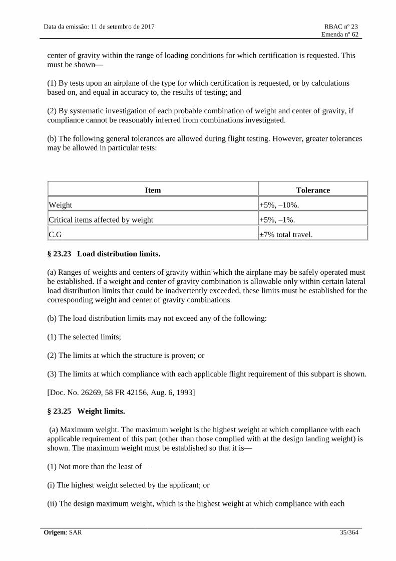
Data da emissão: 11 de setembro de 2017 RBAC nº 23
Emenda nº 62
Origem: SAR 35/364
center of gravity within the range of loading conditions for which certification is requested. This
must be shown—
(1) By tests upon an airplane of the type for which certification is requested, or by calculations
based on, and equal in accuracy to, the results of testing; and
(2) By systematic investigation of each probable combination of weight and center of gravity, if
compliance cannot be reasonably inferred from combinations investigated.
(b) The following general tolerances are allowed during flight testing. However, greater tolerances
may be allowed in particular tests:
Item Tolerance
Weight +5%, –10%.
Critical items affected by weight +5%, –1%.
C.G ±7% total travel.
§ 23.23 Load distribution limits.
(a) Ranges of weights and centers of gravity within which the airplane may be safely operated must
be established. If a weight and center of gravity combination is allowable only within certain lateral
load distribution limits that could be inadvertently exceeded, these limits must be established for the
corresponding weight and center of gravity combinations.
(b) The load distribution limits may not exceed any of the following:
(1) The selected limits;
(2) The limits at which the structure is proven; or
(3) The limits at which compliance with each applicable flight requirement of this subpart is shown.
[Doc. No. 26269, 58 FR 42156, Aug. 6, 1993]
§ 23.25 Weight limits.
(a) Maximum weight. The maximum weight is the highest weight at which compliance with each
applicable requirement of this part (other than those complied with at the design landing weight) is
shown. The maximum weight must be established so that it is—
(1) Not more than the least of—
(i) The highest weight selected by the applicant; or
(ii) The design maximum weight, which is the highest weight at which compliance with each
Data da emissão: 11 de setembro de 2017 RBAC nº 23
Emenda nº 62
Origem: SAR 36/364
applicable structural loading condition of this part (other than those complied with at the design
landing weight) is shown; or
(iii) The highest weight at which compliance with each applicable flight requirement is shown, and
(2) Not less than the weight with—
(i) Each seat occupied, assuming a weight of 170 pounds for each occupant for normal and
commuter category airplanes, and 190 pounds for utility and acrobatic category airplanes, except
that seats other than pilot seats may be placarded for a lesser weight; and
(A) Oil at full capacity, and
(B) At least enough fuel for maximum continuous power operation of at least 30 minutes for day-
VFR approved airplanes and at least 45 minutes for night-VFR and IFR approved airplanes; or
(ii) The required minimum crew, and fuel and oil to full tank capacity.
(b) Minimum weight. The minimum weight (the lowest weight at which compliance with each
applicable requirement of this part is shown) must be established so that it is not more than the sum
of—
(1) The empty weight determined under §23.29;
(2) The weight of the required minimum crew (assuming a weight of 170 pounds for each
crewmember); and
(3) The weight of—
(i) For turbojet powered airplanes, 5 percent of the total fuel capacity of that particular fuel tank
arrangement under investigation, and
(ii) For other airplanes, the fuel necessary for one-half hour of operation at maximum continuous
power.
[Doc. No. 4080, 29 FR 17955, Dec. 18, 1964, as amended by Amdt. 23–7, 34 FR 13086, Aug. 13,
1969; Amdt. 23–21, 43 FR 2317, Jan. 16, 1978; Amdt. 23–34, 52 FR 1825, Jan. 15, 1987; Amdt.
23–45, 58 FR 42156, Aug. 6, 1993; Amdt. 23–50, 61 FR 5183, Feb. 9, 1996]
§ 23.29 Empty weight and corresponding center of gravity.
(a) The empty weight and corresponding center of gravity must be determined by weighing the
airplane with—
(1) Fixed ballast;
(2) Unusable fuel determined under §23.959; and
(3) Full operating fluids, including—
Data da emissão: 11 de setembro de 2017 RBAC nº 23
Emenda nº 62
Origem: SAR 37/364
(i) Oil;
(ii) Hydraulic fluid; and
(iii) Other fluids required for normal operation of airplane systems, except potable water, lavatory
precharge water, and water intended for injection in the engines.
(b) The condition of the airplane at the time of determining empty weight must be one that is well
defined and can be easily repeated.
[Doc. No. 4080, 29 FR 17955, Dec. 18, 1964; 30 FR 258, Jan. 9, 1965, as amended by Amdt. 23–
21, 43 FR 2317, Jan. 16, 1978]
§ 23.31 Removable ballast.
Removable ballast may be used in showing compliance with the flight requirements of this subpart,
if—
(a) The place for carrying ballast is properly designed and installed, and is marked under §23.1557;
and
(b) Instructions are included in the airplane flight manual, approved manual material, or markings
and placards, for the proper placement of the removable ballast under each loading condition for
which removable ballast is necessary.
[Doc. No. 4080, 29 FR 17955, Dec. 18, 1964; 30 FR 258, Jan. 9, 1965, as amended by Amdt. 23–
13, 37 FR 20023, Sept. 23, 1972]
§ 23.33 Propeller speed and pitch limits.
(a) General. The propeller speed and pitch must be limited to values that will assure safe operation
under normal operating conditions.
(b) Propellers not controllable in flight. For each propeller whose pitch cannot be controlled in
flight—
(1) During takeoff and initial climb at the all engine(s) operating climb speed specified in §23.65,
the propeller must limit the engine r.p.m., at full throttle or at maximum allowable takeoff manifold
pressure, to a speed not greater than the maximum allowable takeoff r.p.m.; and
(2) During a closed throttle glide, at VNE, the propeller may not cause an engine speed above 110
percent of maximum continuous speed.
(c) Controllable pitch propellers without constant speed controls. Each propeller that can be
controlled in flight, but that does not have constant speed controls, must have a means to limit the
pitch range so that—
(1) The lowest possible pitch allows compliance with paragraph (b)(1) of this section; and

Data da emissão: 11 de setembro de 2017 RBAC nº 23
Emenda nº 62
Origem: SAR 38/364
(2) The highest possible pitch allows compliance with paragraph (b)(2) of this section.
(d) Controllable pitch propellers with constant speed controls. Each controllable pitch propeller
with constant speed controls must have—
(1) With the governor in operation, a means at the governor to limit the maximum engine speed to
the maximum allowable takeoff r.p.m.; and
(2) With the governor inoperative, the propeller blades at the lowest possible pitch, with takeoff
power, the airplane stationary, and no wind, either—
(i) A means to limit the maximum engine speed to 103 percent of the maximum allowable takeoff
r.p.m., or
(ii) For an engine with an approved overspeed, a means to limit the maximum engine and propeller
speed to not more than the maximum approved overspeed.
[Doc. No. 4080, 29 FR 17955, Dec. 18, 1964, as amended by Amdt. 23–45, 58 FR 42156, Aug. 6,
1993; Amdt. 23–50, 61 FR 5183, Feb. 9, 1996]
Performance
23.45 General.
(a) Unless otherwise prescribed, the
performance requirements of this part must be
met for:
(1) Still air and standard atmosphere; and
(2) Ambient atmospheric conditions, for
commuter category airplanes, for reciprocating
engine-powered airplanes of more than 6.000
pounds (2.722 kg) maximum weight, and for
turbine engine-powered airplanes.
(b) Performance data must be determined over
not less than the following ranges of
conditions:
(1) Airport altitudes from sea level to 10.000
feet; and
(2) For reciprocating engine-powered airplanes
of 6.000 pounds (2.722 kg), or less, maximum
weight, temperature from standard to 30 °C
above standard; or
(3) For reciprocating engine-powered airplanes
of more than 6.000 pounds (2.722 kg)
23.45 Geral.
(a) A menos que prescrito de outra forma, os
requisitos de desempenho desta parte devem
ser cumpridos para:
(1) Ar calmo e atmosfera padrão; e
(2) Condições atmosféricas ambiente, para
aviões da categoria transporte regional, para
aviões com motores convencionais com mais
de 6.000 libras (2.722 kg) de peso máximo e
para aviões propulsados por motores a turbina.
(b) Os dados de desempenho devem ser
determinados numa faixa de condições não
menos abrangente que:
(1) Altitude dos aeródromos do nível do mar
até 10.000 pés; e
(2) Para aviões propulsados por motores
convencionais com peso de 6.000 libras (2.722
kg) ou menos, no peso máximo, numa faixa de
temperaturas variando do padrão até 30 °C
acima do padrão; ou
(3) Para aviões propulsados por motores

Data da emissão: 11 de setembro de 2017 RBAC nº 23
Emenda nº 62
Origem: SAR 39/364
maximum weight and turbine engine-powered
airplanes, temperature from standard to 30 °C
above standard, or the maximum ambient
atmospheric temperature at which compliance
with the cooling provisions of sections 23.1041
to 23.1047 is shown, if lower.
(c) Performance data must be determined with
the cowl flaps or other means for controlling
the engine cooling air supply in the position
used in the cooling tests required by sections
23.1041 to 23.1047.
(d) The available propulsive thrust must
correspond to engine power, not exceeding the
approved power, less:
(1) Installation losses; and
(2) The power absorbed by the accessories and
services appropriate to the particular ambient
atmospheric conditions and the particular flight
condition.
(e) The performance, as affected by engine
power or thrust, must be based on a relative
humidity:
(1) Of 80 percent at and below standard
temperature; and
(2) From 80 percent, at the standard
temperature, varying linearly down to 34
percent at the standard temperature plus 50 °F
(10ºC).
(f) Unless otherwise prescribed, in determining
the takeoff and landing distances, changes in
the airplane's configuration, speed, and power
must be made in accordance with procedures
established by the applicant for operation in
service. These procedures must be able to be
executed consistently by pilots of average skill
in atmospheric conditions reasonably expected
to be encountered in service.
(g) The following, as applicable, must be
determined on a smooth, dry, hard-surfaced
convencionais com peso máximo maior que
6.000 libras (2.722 kg) ou propulsados por
motores à turbina, em temperaturas varrendo
do padrão até 30 °C acima do padrão ou na
máxima temperatura atmosférica ambiente, na
qual é mostrada a conformidade com as
provisões de refrigeração das seções 23.1041 à
23.1047, se mais baixa.
(c) Os dados de desempenho devem ser
determinados com a portinhola de refrigeração
ou outros meios para controlar o suprimento de
ar para refrigeração do motor na posição usada
nos testes de refrigeração requeridos nas seções
23.1041 à 23.1047.
(d) A tração propulsora disponível deve
corresponder à potência do motor, não
excedendo à potência aprovada, menos:
(1) As perdas de instalação; e
(2) A potência absorvida pelos acessórios e os
serviços apropriados para as condições
particulares de ambiente atmosférico e para a
condição particular de voo.
(e) O desempenho, na parte afetada pela
potência ou tração do motor, deve ser baseado
na umidade relativa:
(1) De 80 por cento, na temperatura padrão ou
abaixo dela; e
(2) A partir de 80 por cento, na temperatura
padrão, variando linearmente até 34 por cento
na temperatura padrão mais 50 °F (10 ºC).
(f) A menos que seja prescrito de outra
maneira, na determinação das distâncias para
decolagem e pouso, mudanças na configuração
do avião, velocidade e potência devem ser
feitas de acordo com os procedimentos
operacionais estabelecidos pelo requerente para
operação em serviço. Estes procedimentos
devem ser possíveis de serem executados,
consistentemente, por pilotos de habilidade
mediana e em condições atmosféricas,
razoavelmente esperadas de serem encontradas

Data da emissão: 11 de setembro de 2017 RBAC nº 23
Emenda nº 62
Origem: SAR 40/364
runway—
(1) Takeoff distance of paragraph 23.53(b);
(2) Accelerate-stop distance of section 23.55;
(3) Takeoff distance and takeoff run of section
23.59; and
(4) Landing distance of section 23.75.
Note: The effect on these distances of operation
on other types of surfaces (for example, grass,
gravel) when dry, may be determined or
derived and these surfaces listed in the
Airplane Flight Manual in accordance with
paragraph 23.1583(p).
(h) For multiengine jets weighing over 6.000
pounds (2.722 kg) in the normal, utility, and
acrobatic category and commuter category
airplanes, the following also apply:
(1) Unless otherwise prescribed, the applicant
must select the takeoff, enroute, approach, and
landing configurations for the airplane.
(2) The airplane configuration may vary with
weight, altitude, and temperature, to the extent
that they are compatible with the operating
procedures required by paragraph (h)(3) of this
section.
(3) Unless otherwise prescribed, in determining
the critical-engine-inoperative takeoff
performance, takeoff flight path, and
accelerate-stop distance, changes in the
airplane's configuration, speed, and power must
be made in accordance with procedures
established by the applicant for operation in
service.
(4) Procedures for the execution of
discontinued approaches and balked landings
associated with the conditions prescribed in
paragraphs 23.67(d)(4) and 23.77(c) must be
established.
(5) The procedures established under
em serviço.
(g) Os seguintes dados, quando aplicáveis,
devem ser determinados em uma pista lisa,
seca e superfície dura:
(1) Distância de decolagem do parágrafo
23.53(b);
(2) Distância de aceleração e parada da seção
23.55;
(3) Distância de decolagem e corrida de
decolagem da seção 23.59; e
(4) Distância de pouso da seção 23.75.
Nota: O efeito nestas distâncias em operações
em outros tipos de superfície (por exemplo,
grama, cascalho), quando secas, pode ser
determinado ou derivado e estas superfícies
listadas no manual de voo aprovado de acordo
com parágrafo 23.1583(p).
(h) Para jatos multimotores pesando acima de
6,000 libras (2.722 kg) das categorias normal,
utilidade, e acrobática e aviões da categoria
transporte regional, também se aplica o
seguinte:
(1) A menos que seja prescrito de outra
maneira, o requerente deve indicar as
configurações dos aviões para decolagem,
cruzeiro, aproximação e pouso.
(2) A configuração do avião pode variar com o
peso, altitude e temperatura, desde que elas
sejam compatíveis com os procedimentos
operacionais requeridos pelo parágrafo (h)(3)
desta seção.
(3) A menos que seja prescrito de outra
maneira, na determinação do desempenho de
decolagem com motor crítico inoperante,
trajetória de voo na decolagem e distância de
aceleração e parada, mudanças na configuração
do avião, velocidade e potência devem ser
feitas de acordo com os procedimentos
estabelecidos pelo requerente para a operação

Data da emissão: 11 de setembro de 2017 RBAC nº 23
Emenda nº 62
Origem: SAR 41/364
paragraphs (h)(3) and (h)(4) of this section
must:
(i) Be able to be consistently executed by a
crew of average skill in atmospheric conditions
reasonably expected to be encountered in
service;
(ii) Use methods or devices that are safe and
reliable; and
(iii) Include allowance for any reasonably
expected time delays in the execution of the
procedures.
em serviço.
(4) Devem ser estabelecidos procedimentos
para a execução de aproximações
descontinuadas e arremetidas no pouso,
associadas com as condições prescritas nos
parágrafos 23.67(d)(4) e 23.77(c).
(5) Os procedimentos estabelecidos sob os
parágrafos (h)(3) e (h)(4) desta seção devem:
(i) Ser capazes de, consistentemente, serem
executados por um tripulante de habilidade
mediana e em uma condição atmosférica
razoavelmente esperada de se encontrar em
serviço;
(ii) Usar métodos ou dispositivos que sejam
seguros e confiáveis; e
(iii) Incluir tolerância para qualquer atraso de
tempo razoável esperado na execução dos
procedimentos.
[Doc. No. 27807, 61 FR 5184, Feb. 9, 1996, as amended by Amdt. 23-62, 76 FR 75753, Dec. 2,
2011]
[Resolução nº 446, de 06.09.2017]
23.49 Stalling speed.
(a) VS0 (maximum landing flap configuration)
and VS1 are the stalling speeds or the minimum
steady flight speeds, in knots (CAS), at which
the airplane is controllable with:
(1) For reciprocating engine-powered airplanes,
the engine(s) idling, the throttle(s) closed or at
not more than the power necessary for zero
thrust at a speed not more than 110 percent of
the stalling speed;
(2) For turbine engine-powered airplanes, the
propulsive thrust not greater than zero at the
stalling speed, or, if the resultant thrust has no
appreciable effect on the stalling speed, with
engine(s) idling and throttle(s) closed;
23.49 Velocidade de estol.
(a) VS0 (configuração com máximos flapes de
pouso) e VS1 são as velocidades de estol ou
velocidades mínimas de voo estabilizado, em
nós (CAS), nas quais o avião é controlável
com:
(1) Para aviões propelidos por motores
convencionais, o(s) motor(es) em marcha lenta,
a(s) manete(s) de potência fechada(s) ou em
não mais do que a potência necessária para
tração zero a uma velocidade não superior a
110 por cento da velocidade de estol;
(2) Para aviões propelidos por motores à
turbina, o empuxo não maior que zero na
velocidade de estol, ou, se o empuxo resultante
não tiver efeito apreciável na velocidade de
estol, com o(s) motor(es) em marcha lenta e

Data da emissão: 11 de setembro de 2017 RBAC nº 23
Emenda nº 62
Origem: SAR 42/364
(3) The propeller(s) in the takeoff position;
(4) The airplane in the condition existing in the
test, in which VS0 and VS1 are being used;
(5) The center of gravity in the position that
results in the highest value of VS0 and VS1; and
(6) The weight used when VS0 and VS1 are
being used as a factor to determine compliance
with a required performance standard.
(b) VS0 and VS1 must be determined by flight
tests, using the procedure and meeting the
flight characteristics specified in section
23.201.
(c) Except as provided in paragraph (d) of this
section, VS0 at maximum weight may not
exceed 61 knots (31,4 m/s) for:
(1) Single-engine airplanes; and
(2) Multiengine airplanes of 6.000 pounds
(2.722 kg) or less maximum weight that cannot
meet the minimum rate of climb specified in
paragraph 23.67(a) (1) with the critical engine
inoperative.
(d) All single-engine airplanes, and those
multiengine airplanes of 6.000 pounds (2.722
kg) or less maximum weight with a VS0 of
more than 61 knots that do not meet the
requirements of paragraph 23.67(a)(1), must
comply with paragraph 23.562(d).
a(s) manete(s) de potência fechada(s);
(3) A(s) hélice(s) na posição de decolagem;
(4) O avião na condição existente no ensaio, no
qual a VS0 e VS1 estão sendo usadas;
(5) O centro de gravidade na posição que
resulta no maior valor da VS0 e VS1; e
(6) O peso utilizado quando a VS0 e VS1 estão
sendo usadas como um fator para determinar
cumprimento com uma norma de desempenho
requerida.
(b) VS0 e VS1 devem ser determinadas por
ensaios em voo, usando o procedimento e
satisfazendo as características de voo
especificados na seção 23.201.
(c) Exceto como previsto no parágrafo (d) desta
seção, a VS0 no peso máximo não pode exceder
61 nós (31,4 m/s) para:
(1) Aviões monomotores; e
(2) Aviões multimotores de 6.000 libras (2.722
kg) ou menos de peso máximo que não
conseguem cumprir a razão mínima de subida
especificada no parágrafo 23.67(a)(1) com o
motor crítico inoperante.
(d) Todos os aviões monomotores, e aqueles
aviões multimotores de 6.000 libras (2.722 kg)
ou menos de peso máximo com uma VS0 de
mais que 61 nós (31,4 m/s) que não cumprem
os requisitos do parágrafo 23.67(a)(1), devem
cumprir com o parágrafo 23.562(d).
[Doc. No. 27807, 61 FR 5184, Feb. 9, 1996, as amended by Amdt. 23-62, 76 FR 75753, Dec. 2,
2011]
[Resolução nº 446, de 06.09.2017]
23.51 Takeoff speeds.
(a) For normal, utility, and acrobatic category
airplanes, rotation speed, VR, is the speed at
which the pilot makes a control input, with the
23.51 Velocidades de decolagem.
(a) Para aviões das categorias normal, utilidade
e acrobática, a velocidade de rotação, VR, é a
velocidade na qual o piloto executa um

Data da emissão: 11 de setembro de 2017 RBAC nº 23
Emenda nº 62
Origem: SAR 43/364
intention of lifting the airplane out of contact
with the runway or water surface.
(1) For multiengine landplanes, VR, must not
be less than the greater of 1,05 VMC; or 1,10
VS1;
(2) For single-engine landplanes, VR, must not
be less than VS1; and
(3) For seaplanes and amphibians taking off
from water, VR, may be any speed that is
shown to be safe under all reasonably expected
conditions, including turbulence and complete
failure of the critical engine.
(b) For normal, utility, and acrobatic category
airplanes, the speed at 50 feet (15,24 m) above
the takeoff surface level must not be less than:
(1) For multiengine airplanes, the highest of:
(i) A speed that is shown to be safe for
continued flight (or emergency landing, if
applicable) under all reasonably expected
conditions, including turbulence and complete
failure of the critical engine;
(ii) 1,10 VMC; or
(iii) 1,20 VS1.
(2) For single-engine airplanes, the higher of:
(i) A speed that is shown to be safe under all
reasonably expected conditions, including
turbulence and complete engine failure; or
(ii) 1,20 VS1.
(c) For normal, utility, and acrobatic category
multiengine jets of more than 6.000 pounds
(2.722 kg) maximum weight and commuter
category airplanes, the following apply:
(1) V1 must be established in relation to VEF as
follows:
(i) VEF is the calibrated airspeed at which the
comando nos controles com a intenção de
levantar o avião do contato com a pista ou
superfície da água.
(1) Para aviões terrestres multimotores, a VR
não pode ser menor que o maior entre 1,05 VMC
ou 1,10 VS1;
(2) Para aviões terrestres monomotores, a VR,
não pode ser inferior a VS1; e
(3) Para hidroaviões e aviões anfíbios
decolando da água, a VR, pode ser qualquer
velocidade que seja demonstrada segura sob
todas as condições razoavelmente esperadas,
incluindo turbulência e falha completa do
motor crítico.
(b) Para aviões das categorias normal, utilidade
e acrobática, a velocidade a 50 pés (15,24 m)
acima do nível da superfície de decolagem não
pode ser inferior a:
(1) Para aviões multimotores, o maior entre:
(i) Uma velocidade que seja demonstrada
segura para a continuidade do voo (ou pouso de
emergência, se aplicável), sob todas as
condições razoavelmente esperadas, incluindo
turbulência e falha completa do motor crítico;
(ii) 1,10 VMC, ou
(iii) 1,20 VS1.
(2) Para aviões monomotores, o maior entre:
(i) Uma velocidade que seja demonstrada
segura sob todas as condições razoavelmente
esperadas, incluindo turbulência e falha
completa de motor; ou
(ii) 1,20 VS1.
(c) Para aviões a jato multimotores com peso
máximo superior a 6.000 libras (2.722 kg) das
categorias normal, utilidade e acrobática, e para
aviões das categorias transporte regional,

Data da emissão: 11 de setembro de 2017 RBAC nº 23
Emenda nº 62
Origem: SAR 44/364
critical engine is assumed to fail. VEF must be
selected by the applicant but must not be less
than 1,05 VMC determined under paragraph
23.149(b) or, at the option of the applicant, not
less than VMCG determined under paragraph
23.149(f).
(ii) The takeoff decision speed, V1, is the
calibrated airspeed on the ground at which, as a
result of engine failure or other reasons, the
pilot is assumed to have made a decision to
continue or discontinue the takeoff. The takeoff
decision speed, V1, must be selected by the
applicant but must not be less than VEF plus the
speed gained with the critical engine
inoperative during the time interval between
the instant at which the critical engine is failed
and the instant at which the pilot recognizes
and reacts to the engine failure, as indicated by
the pilot's application of the first retarding
means during the accelerate-stop determination
of paragraph 23.55.
(2) The rotation speed, VR, in terms of
calibrated airspeed, must be selected by the
applicant and must not be less than the greatest
of the following:
(i) V1;
(ii) 1,05 VMC determined under paragraph
23.149(b);
(iii) 1,10 VS1; or
(iv) The speed that allows attaining the initial
climb-out speed, V2, before reaching a height
of 35 feet (10,67 m) above the takeoff surface
in accordance with paragraph 23.57(c)(2).
(3) For any given set of conditions, such as
weight, altitude, temperature, and
configuration, a single value of VR must be
used to show compliance with both the one-
engine-inoperative takeoff and all-engines-
operating takeoff requirements.
(4) The takeoff safety speed, V2, in terms of
calibrated airspeed, must be selected by the
aplica-se o seguinte:
(1) A V1 deve ser estabelecida em relação à
VEF como segue:
(i) VEF é a velocidade calibrada na qual é
assumida a falha do motor crítico. A VEF deve
ser selecionada pelo requerente, mas não pode
ser inferior a 1,05 VMC determinada conforme o
parágrafo 23.149(b) ou, por opção do
requerente, não inferior a VMCG determinada
conforme o parágrafo 23.149(f).
(ii) A velocidade de decisão na decolagem, V1,
é a velocidade calibrada no solo na qual,
devido a falha de motor ou outras razões, é
assumido que o piloto tenha tomado a decisão
de continuar ou interromper a decolagem. A
velocidade de decisão na decolagem, V1, deve
ser selecionada pelo requerente, mas não pode
ser inferior à VEF mais a velocidade ganha com
o motor crítico inoperante durante o intervalo
de tempo entre o instante em que o motor
crítico falha e o instante em que o piloto
reconhece e reage à falha do motor, como
indicado pela aplicação pelo piloto do primeiro
meio de desaceleração durante a determinação
da aceleração e parada da seção 23.55.
(2) A velocidade de rotação, VR, expressa em
termos de velocidade calibrada, deve ser
escolhida pelo requerente e não pode ser
inferior ao maior dos seguintes valores:
(i) V1;
(ii) 1,05 VMC determinada conforme o
parágrafo 23.149(b);
(iii) 1,10 VS1; ou
(iv) A velocidade que permita atingir a
velocidade inicial de subida, V2, antes de
atingir uma altura de 35 pés (10,67 m) acima
da superfície da decolagem, de acordo com o
parágrafo 23.57(c)(2).
(3) Para qualquer conjunto de condições, tais
como peso, altitude, temperatura e

Data da emissão: 11 de setembro de 2017 RBAC nº 23
Emenda nº 62
Origem: SAR 45/364
applicant so as to allow the gradient of climb
required in paragraphs 23.67 (d)(1) and (d)(2)
but must not be less than 1,10 VMC or less than
1,20 VS1.
(5) The one-engine-inoperative takeoff
distance, using a normal rotation rate at a speed
5 knots (2,6 m/s) less than VR, established in
accordance with paragraph (c)(2) of this
section, must be shown not to exceed the
corresponding one-engine-inoperative takeoff
distance, determined in accordance with
section 23.57 and paragraph 23.59(a)(1), using
the established VR. The takeoff, otherwise
performed in accordance with section 23.57,
must be continued safely from the point at
which the airplane is 35 feet (10,67 m) above
the takeoff surface and at a speed not less than
the established V2 minus 5 knots (2,6 m/s).
(6) The applicant must show, with all engines
operating, that marked increases in the
scheduled takeoff distances, determined in
accordance with paragraph 23.59(a)(2), do not
result from over-rotation of the airplane or out-
of-trim conditions.
configuração, um único valor da VR deve ser
utilizado para demonstrar o cumprimento dos
requisitos de decolagem, tanto com um motor
inoperante como com todos os motores
operando.
(4) A velocidade segura de decolagem, V2,
expressa em termos de velocidade calibrada,
deve ser selecionada pelo requerente de modo a
permitir o gradiente de subida requerido no
parágrafo 23.67(d)(1) e (d)(2), mas não pode
ser inferior a 1,10 VMC ou inferior a 1,20 VS1.
(5) A distância de decolagem com um motor
inoperante, usando uma razão de rotação
normal, a uma velocidade 5 nós (2,6 m/s)
inferior à VR, estabelecida de acordo com o
parágrafo (c)(2) desta seção, deve ser
demonstrada não exceder a correspondente
distância de decolagem com um motor
inoperante, determinada de acordo com seção
23.57 e parágrafo 23.59(a)(1), usando a VR
estabelecida. A decolagem, em outros aspectos
realizada de acordo com a seção 23.57, deve
ser continuada em segurança a partir do ponto
em que o avião está 35 pés (10,67 m) acima da
superfície de decolagem e a uma velocidade
não inferior à V2 estabelecida menos 5 nós (2,6
m/s).
(6) O requerente deve demonstrar, com todos
os motores operando, que rotação excessiva do
avião ou condições fora da compensação não
resultam em aumentos significativos nas
distâncias de decolagem previstas,
determinadas de acordo com o parágrafo
23.59(a)(2).
[Doc. No. 27807, 61 FR 5184, Feb. 9, 1996, as amended by Amdt. 23-62, 76 FR 75753, Dec. 2,
2011]
[Resolução nº 446, de 06.09.2017]
23.53 Takeoff performance.
(a) For normal, utility, and acrobatic category
airplanes, the takeoff distance must be
determined in accordance with paragraph (b) of
this section, using speeds determined in
23.53 Desempenho de decolagem.
(a) Para aviões das categorias normal, utilidade
e acrobática, a distância de decolagem deve ser
determinada de acordo com o parágrafo (b)
desta seção, utilizando as velocidades

Data da emissão: 11 de setembro de 2017 RBAC nº 23
Emenda nº 62
Origem: SAR 46/364
accordance with paragraph 23.51 (a) and (b).
(b) For normal, utility, and acrobatic category
airplanes, the distance required to takeoff and
climb to a height of 50 feet (15,24 m) above the
takeoff surface must be determined for each
weight, altitude, and temperature within the
operational limits established for takeoff with:
(1) Takeoff power on each engine;
(2) Wing flaps in the takeoff position(s); and
(3) Landing gear extended.
(c) For normal, utility, and acrobatic category
multiengine jets of more than 6.000 pounds
(2.722 kg) maximum weight and commuter
category airplanes, takeoff performance, as
required by sections 23.55 through 23.59, must
be determined with the operating engine(s)
within approved operating limitations.
determinadas de acordo com os parágrafos
23.51(a) e (b).
(b) Para aviões das categorias normal, utilidade
e acrobática, a distância necessária para decolar
e subir a uma altura de 50 pés (15,24 m) acima
da superfície de decolagem deve ser
determinada para cada peso, altitude e
temperatura dentro dos limites operacionais
estabelecidos para a decolagem com:
(1) Potência de decolagem em cada motor;
(2) Flapes das asas na(s) posição(ões) de
decolagem; e
(3) Trem de pouso estendido.
(c) Para aviões multimotores a jato das
categorias normal, utilidade e acrobática de
mais de 6000 libras (2.722 kg) de peso máximo
e para aviões da categoria transporte regional, o
desempenho de decolagem, como requerido
pelas seções 23.55 a 23.59, deve ser
determinado com o(s) motor(es) operantes
dentro das limitações operacionais aprovadas.
[Doc. No. 27807, 61 FR 5185, Feb. 9, 1996, as amended by Amdt. 23-62, 76 FR 75753, Dec. 2,
2011]
[Resolução nº 446, de 06.09.2017]
23.55 Accelerate-stop distance.
For normal, utility, and acrobatic category
multiengine jets of more than 6.000 pounds
(2.722 kg) maximum weight and commuter
category airplanes, the accelerate-stop distance
must be determined as follows:
(a) The accelerate-stop distance is the sum of
the distances necessary to:
(1) Accelerate the airplane from a standing start
to VEF with all engines operating;
(2) Accelerate the airplane from VEF to V1,
assuming the critical engine fails at VEF; and
23.55 Distância de aceleração e parada.
Para aviões multimotores a jato das categorias
normal, utilidade e acrobática com mais que
6.000 libras (2.722 kg) de peso máximo e
aviões da categoria transporte regional, a
distância de aceleração e parada deve ser
determinada como segue:
(a) A distância de aceleração e parada é a soma
das distâncias necessárias para:
(1) Acelerar o avião da imobilidade até a VEF
com todos os motores operando;
(2) Acelerar o avião da VEF até a V1,

Data da emissão: 11 de setembro de 2017 RBAC nº 23
Emenda nº 62
Origem: SAR 47/364
(3) Come to a full stop from the point at which
V1 is reached.
(b) Means other than wheel brakes may be used
to determine the accelerate-stop distances if
that means:
(1) Is safe and reliable;
(2) Is used so that consistent results can be
expected under normal operating conditions;
and
(3) Is such that exceptional skill is not required
to control the airplane.
assumindo que o motor crítico falha na VEF; e
(3) Realizar uma parada completa a partir do
ponto em que a V1 é atingida.
(b) Outros meios que não os freios de roda
podem ser usados para determinar as distâncias
de aceleração e parada se este meio:
(1) É seguro e confiável;
(2) É usado de forma que resultados
consistentes podem ser esperados em condições
normais de operação; e
(3) É tal que habilidade excepcional não é
requerida para controlar o avião.
[Amdt. 23-34, 52 FR 1826, Jan. 15, 1987, as amended by Amdt. 23-50, 61 FR 5185, Feb. 9, 1996,
as amended by Amdt. 23-62, 76 FR 75753, Dec. 2, 2011]
[Resolução nº 446, de 06.09.2017]
23.57 Takeoff path.
For normal, utility, and acrobatic category
multiengine jets of more than 6.000 pounds
(2.722 kg) maximum weight and commuter
category airplanes, the takeoff path is as
follows:
(a) The takeoff path extends from a standing
start to a point in the takeoff at which the
airplane is 1.500 feet (457,20 m) above the
takeoff surface at or below which height the
transition from the takeoff to the enroute
configuration must be completed; and
(1) The takeoff path must be based on the
procedures prescribed in section 23.45;
(2) The airplane must be accelerated on the
ground to VEF at which point the critical engine
must be made inoperative and remain
inoperative for the rest of the takeoff; and
(3) After reaching VEF, the airplane must be
accelerated to V2.
23.57 Trajetória de decolagem.
Para aviões a jato multimotores com peso
máximo superior a 6.000 libras (2.722 kg) das
categorias normal, utilidade e acrobática, e para
aviões da categoria transporte regional, a
trajetória de decolagem é definida como segue:
(a) A trajetória de decolagem se estende desde
a imobilidade até o ponto da decolagem no
qual o avião está a 1.500 pés (457,20 m) acima
da superfície de decolagem, no qual ou abaixo
do qual a transição da configuração de
decolagem para a de cruzeiro deve ser
completada; e
(1) A trajetória de decolagem deve ser baseada
nos procedimentos prescritos na seção 23.45;
(2) O avião deve ser acelerado no solo até a
VEF, ponto no qual o motor crítico deve ser
feito inoperante e permanecer inoperante pelo
resto da decolagem; e
(3) Depois de atingir a VEF, o avião deve ser
Data da emissão: 11 de setembro de 2017 RBAC nº 23
Emenda nº 62
Origem: SAR 48/364
(b) During the acceleration to speed V2, the
nose gear may be raised off the ground at a
speed not less than VR. However, landing gear
retraction must not be initiated until the
airplane is airborne.
(c) During the takeoff path determination, in
accordance with paragraphs (a) and (b) of this
section:
(1) The slope of the airborne part of the takeoff
path must not be negative at any point;
(2) The airplane must reach V2 before it is 35
feet (10,67 m) above the takeoff surface, and
must continue at a speed as close as practical
to, but not less than V2, until it is 400 feet
(121,92 m) above the takeoff surface;
(3) At each point along the takeoff path,
starting at the point at which the airplane
reaches 400 feet (121,92 m) above the takeoff
surface, the available gradient of climb must
not be less than:
(i) 1,2 percent for two-engine airplanes;
(ii) 1,5 percent for three-engine airplanes;
(iii) 1,7 percent for four-engine airplanes; and
(4) Except for gear retraction and automatic
propeller feathering, the airplane configuration
must not be changed, and no change in power
that requires action by the pilot may be made,
until the airplane is 400 feet (121,92 m) above
the takeoff surface.
(d) The takeoff path to 35 feet (10,67 m)above
the takeoff surface must be determined by a
continuous demonstrated takeoff.
(e) The takeoff path to 35 feet (10,67 m) above
the takeoff surface must be determined by
synthesis from segments; and
(1) The segments must be clearly defined and
must be related to distinct changes in
acelerado para a V2.
(b) Durante a aceleração até a velocidade V2, o
trem de pouso do nariz pode ser tirado do solo
a uma velocidade não inferior à VR. Contudo, a
retração do trem de pouso não pode ser iniciada
até que o avião esteja no ar.
(c) Durante a determinação da trajetória de
decolagem, de acordo com os parágrafos (a) e
(b) desta seção:
(1) A inclinação da parte aérea da trajetória de
decolagem não pode ser negativa em nenhum
ponto;
(2) O avião deve atingir a V2 antes de alcançar
35 pés (10,67 m) acima da superfície de
decolagem e deve continuar em uma
velocidade tão próxima quanto possível, mas
não inferior a V2, até que ele esteja 400 pés
(121,92 m) acima da superfície de decolagem;
(3) Em cada ponto ao longo da trajetória de
decolagem, iniciando no ponto em que o avião
atinge 400 pés (121,92 m) acima da superfície
da decolagem, o gradiente de subida disponível
não pode ser menor que:
(i) 1,2 por cento para aviões bimotores;
(ii) 1,5 por cento para aviões trimotores, e
(iii) 1,7 por cento para aviões quadrimotores; e
(4) A configuração do avião não pode ser
alterada, exceto pela retração do trem de pouso
e embandeiramento automático de hélice, e
nenhuma mudança na potência que requeira
ação do piloto deve ser feita até que o avião
esteja 400 pés (121,92 m) acima da superfície
de decolagem.
(d) A trajetória de decolagem até 35 pés (10,67
m) acima da superfície de decolagem deve ser
determinada através da demonstração de uma
decolagem contínua.
(e) A trajetória de decolagem a partir de 35 pés
Data da emissão: 11 de setembro de 2017 RBAC nº 23
Emenda nº 62
Origem: SAR 49/364
configuration, power, and speed;
(2) The weight of the airplane, the
configuration, and the power must be assumed
constant throughout each segment and must
correspond to the most critical condition
prevailing in the segment; and
(3) The takeoff flight path must be based on the
airplane's performance without utilizing ground
effect.
(10,67 m) acima da superfície de decolagem
deve ser determinada pela síntese de
segmentos; e
(1) Os segmentos devem ser claramente
definidos e devem estar relacionados a nítidas
alterações na configuração, potência e
velocidade;
(2) O peso do avião, a configuração e a
potência devem ser assumidos constantes ao
longo de cada segmento e devem corresponder
à condição mais crítica predominante no
segmento; e
(3) A trajetória em voo da decolagem deve ser
baseada no desempenho do avião sem utilizar o
efeito de solo.
[Amdt. 23-34, 52 FR 1827, Jan. 15, 1987, as amended by Amdt. 23-50, 61 FR 5185, Feb. 9, 1996,
as amended by Amdt. 23-62, 76 FR 75753, Dec. 2, 2011]
[Resolução nº 446, de 06.09.2017]
23.59 Takeoff distance and takeoff run.
For normal, utility, and acrobatic category
multiengine jets of more than 6.000 pounds
(2.722 kg) maximum weight and commuter
category airplanes, the takeoff distance and, at
the option of the applicant, the takeoff run,
must be determined.
(a) Takeoff distance is the greater of:
(1) The horizontal distance along the takeoff
path from the start of the takeoff to the point at
which the airplane is 35 feet (10,67 m) above
the takeoff surface as determined under section
23.57; or
(2) With all engines operating, 115 percent of
the horizontal distance from the start of the
takeoff to the point at which the airplane is 35
feet (10,67 m) above the takeoff surface,
determined by a procedure consistent with
section 23.57.
(b) If the takeoff distance includes a clearway,
23.59 Distância de decolagem e corrida de
decolagem.
Para aviões multimotores a jato de categoria
normal, utilidade e acrobática de mais de 6000
libras (2.722 kg) de peso máximo e para aviões
da categoria transporte regional, a distância de
decolagem e, por opção do requerente, a
corrida de decolagem, deve ser determinada.
(a) A distância de decolagem é a maior entre:
(1) A distância horizontal ao longo da trajetória
de decolagem a partir do início da decolagem
até o ponto em que o avião está 35 pés (10,67
m) acima da superfície de decolagem como
determinado pela seção 23.57; ou
(2) Com todos os motores operando, 115 por
cento da distância horizontal do início da
decolagem até o ponto em que o avião está 35
pés (10,67 m) acima da superfície de
decolagem, determinada por um procedimento
consistente com a seção 23.57.

Data da emissão: 11 de setembro de 2017 RBAC nº 23
Emenda nº 62
Origem: SAR 50/364
the takeoff run is the greater of:
(1) The horizontal distance along the takeoff
path from the start of the takeoff to a point
equidistant between the liftoff point and the
point at which the airplane is 35 feet (10,67 m)
above the takeoff surface as determined under
section 23.57; or
(2) With all engines operating, 115 percent of
the horizontal distance from the start of the
takeoff to a point equidistant between the liftoff
point and the point at which the airplane is 35
feet (10,67 m) above the takeoff surface,
determined by a procedure consistent with
section 23.57.
(b) Se a distância de decolagem incluir uma
“clearway”, a corrida de decolagem é a maior
entre:
(1) A distância horizontal ao longo da trajetória
de decolagem a partir do início da decolagem
até um ponto equidistante entre o ponto em que
o avião deixa o solo e o ponto em que o avião
está 35 pés (10,67 m) acima da superfície de
decolagem, como determinada pela seção
23.57; ou
(2) Com todos os motores operando, 115 por
cento da distância horizontal do início da
decolagem até um ponto equidistante entre o
ponto em que o avião deixa o solo e o ponto em
que o avião está 35 pés (10,67 m) acima da
superfície de decolagem, determinada por um
procedimento consistente com a seção 23.57.
[Amdt. 23-34, 52 FR 1827, Jan. 15, 1987, as amended by Amdt. 23-50, 61 FR 5185, Feb. 9, 1996,
as amended by Amdt. 23-62, 76 FR 75753, Dec. 2, 2011]
[Resolução nº 446, de 06.09.2017]
23.61 Takeoff flight path.
For normal, utility, and acrobatic category
multiengine jets of more than 6,000 pounds
maximum weight and commuter category
airplanes, the takeoff flight path must be
determined as follows:
(a) The takeoff flight path begins 35 feet (10,67
m) above the takeoff surface at the end of the
takeoff distance determined in accordance with
section 23.59.
(b) The net takeoff flight path data must be
determined so that they represent the actual
takeoff flight paths, as determined in
accordance with section 23.57 and with
paragraph (a) of this section, reduced at each
point by a gradient of climb equal to:
(1) 0,8 percent for two-engine airplanes;
(2) 0,9 percent for three-engine airplanes; and
23.61 Trajetória em voo da decolagem.
Para aviões multimotores à jato da categoria
normal, utilidade e acrobática com mais que
6.000 libras (2.722 kg) de peso máximo e
aviões da categoria transporte regional, a
trajetória em voo da decolagem deve ser
determinada como segue:
(a) A trajetória em voo da decolagem começa a
35 pés (10,67 m) acima da superfície de
decolagem ao final da distância de decolagem,
determinada de acordo com a seção 23.59.
(b) Os dados da trajetória em voo líquida da
decolagem devem ser determinados de modo
que eles representem a real trajetória em voo da
decolagem, determinada conforme a seção
23.57 e com o parágrafo (a) desta seção,
reduzidas em cada ponto por um gradiente de
subida igual a:
(1) 0,8 por cento para aviões bimotores;
Data da emissão: 11 de setembro de 2017 RBAC nº 23
Emenda nº 62
Origem: SAR 51/364
(3) 1,0 percent for four-engine airplanes.
(c) The prescribed reduction in climb gradient
may be applied as an equivalent reduction in
acceleration along that part of the takeoff flight
path at which the airplane is accelerated in
level flight.
(2) 0,9 por cento para aviões trimotores; e
(3) 1,0 por cento para aviões quadrimotores.
(c) A redução prescrita no gradiente de subida
deve ser aplicada como uma redução
equivalente na aceleração ao longo da parte da
trajetória em voo da decolagem na qual o avião
é acelerado em voo nivelado.
[Amdt. 23-34, 52 FR 1827, Jan. 15, 1987, as amended by Amdt. 23-62, 76 FR 75753, Dec. 2, 2011]
[Resolução nº 446, de 06.09.2017]
23.63 Climb: General.
(a) Compliance with the requirements of
sections 23.65, 23.66, 23.67, 23.69, and 23.77
must be shown:
(1) Out of ground effect; and
(2) At speeds that are not less than those at
which compliance with the powerplant cooling
requirements of sections 23.1041 to 23.1047
has been demonstrated; and
(3) Unless otherwise specified, with one engine
inoperative, at a bank angle not exceeding 5
degrees.
(b) For normal, utility, and acrobatic category
reciprocating engine-powered airplanes of
6.000 pounds (2.722 kg) or less maximum
weight, compliance must be shown with
paragraphs 23.65(a), 23.67(a), where
appropriate, and paragraph 23.77(a) at
maximum takeoff or landing weight, as
appropriate, in a standard atmosphere.
(c) For each of the following normal, utility,
and acrobatic category airplanes: (1)
reciprocating engine-powered airplanes of
more than 6.000 pounds (2.722 kg) maximum
weight, (2) single engine turbines, and (3)
multiengine turbine airplanes of 6.000 pounds
(2.722 kg) or less maximum weight,
compliance must be shown at weights as a
function of airport altitude and ambient
23.63 Subida: Geral.
(a) O cumprimento com os requisitos das
seções 23.65, 23.66, 23.67, 23.69 e 23.77
devem ser demonstrados:
(1) Fora do efeito de solo; e
(2) Em velocidades que não sejam menores do
que aquelas nas quais o cumprimento com os
requisitos de refrigeração do grupo
motopropulsor das seções 23.1041 a 23.1047
tenha sido demonstrado; e
(3) A menos que especificado de outra
maneira, com um motor inoperante, em um
ângulo de inclinação lateral não superior a 5
graus.
(b) Para aviões das categorias normal, utilidade
e acrobática, propelidos por motores
convencionais, e com até 6.000 libras (2.722
kg) de peso máximo, deve ser demonstrado o
cumprimento com os parágrafos 23.65(a),
23.67(a), onde for apropriado, e parágrafo
23.77(a) no peso máximo de decolagem ou
pouso, o que for apropriado, em uma atmosfera
padrão.
(c) Para todos os seguintes aviões das
categorias normal, utilidade e acrobática: (1)
aviões propelidos por motores convencionais e
com peso máximo superior a 6.000 libras
(2.722 kg), (2) aviões monomotor à turbina, e
(3) aviões multimotores à turbina de peso

Data da emissão: 11 de setembro de 2017 RBAC nº 23
Emenda nº 62
Origem: SAR 52/364
temperature within the operational limits
established for takeoff and landing,
respectively, with:
(1) For reciprocating engine-power airplanes of
more than 6.000 pounds (2.722 kg) maximum
weight:
(i) Paragraphs 23.65(b) and 23.67(b)(1) and
(2), where appropriate, for takeoff and
(ii) Paragraphs 23.67(b)(2), where appropriate,
and 23.77(b), for landing,
(2) For single-engine turbines:
(i) Paragraph 23.65(b), for takeoff, and
(ii) Paragraph 23.77(b) for landing.
(3) For multiengine turbine airplanes of 6.000
pounds (2.722 kg) or less maximum weight:
(i) For takeoff, 23.65(b) and
(A) If a turbopropeller-power airplane,
23.67(b)(1), and (2), where appropriate.
(B) If a jet airplane, 23.67(c)(1), and (2), where
appropriate.
(ii) For landing, 23.77(b) and
(A) If a turbopropeller-powered airplane,
23.67(b)(2), where appropriate.
(B) If a jet airplane, 23.67(c)(2), where
appropriate.
(d) For multiengine turbine airplanes over
6.000 pounds (2.722 kg) maximum weight in
the normal, utility, and acrobatic category and
commuter category airplanes, compliance must
be shown at weights as a function of airport
altitude and ambient temperature within the
operational limits established for takeoff and
landing, respectively, with:
(1) If a normal, utility, or acrobatic category,
máximo igual ou inferior a 6.000 libras (2.722
kg), o cumprimento deve ser demonstrado com
pesos como uma função da altitude do
aeródromo e temperatura ambiente, dentro dos
limites operacionais estabelecidos para
decolagem e pouso, respectivamente, com:
(1) Para aviões propelidos por motores
convencionais e com peso máximo superior a
6.000 libras (2.722 kg):
(i) Parágrafos 23.65(b) e 23.67(b)(1) e (2),
onde apropriado, para a decolagem, e
(ii) parágrafo 23.67(b)(2), onde apropriado, e
23.77(b), para o pouso,
(2) Para aviões monomotor à turbina:
(i) Parágrafo 23.65(b), para a decolagem, e
(ii) Parágrafo 23.77(b), para o pouso,
(3) Para aviões multimotores à turbinas de peso
máximo igual ou inferior a 6.000 libras (2.722
kg):
(i) Para a decolagem, 23.65(b), e
(A) Se um avião turboélice, 23.67(b)(1) e (2),
onde apropriado.
(B) Se um avião a jato, 23.67(c)(1) e (2), onde
apropriado.
(ii) Para o pouso, 23.77(b) e
(A) Se um avião turboélice, 23.67(b)(2), onde
apropriado.
(B) Se um avião a jato, 23.67(c)(2), onde
apropriado.
(d) Para aviões multimotores à turbina com
peso máximo superior a 6.000 libras (2.722 kg)
das categorias normal, utilidade e acrobática, e
para aviões da categoria transporte regional, o
cumprimento deve ser demonstrado com pesos
como uma função da altitude do aeródromo e

Data da emissão: 11 de setembro de 2017 RBAC nº 23
Emenda nº 62
Origem: SAR 53/364
turbopropeller-powered airplane:
(i) Paragraphs 23.67(b)(1), and (2), where
appropriate, for takeoff, and
(ii) Paragraph 23.67(b)(2), where appropriate,
and 23.77(c), for landing
(2) If a jet or commuter category airplane:
(i) Paragraphs 23.67(d)(1), (2), and (3), where
appropriate, for takeoff, and
(ii) Paragraphs 23.67(d)(3), and (4), where
appropriate, and 23.77(c) for landing.
temperatura ambiente dentro dos limites
operacionais estabelecidos para decolagem e
pouso, respectivamente, com:
(1) Se um avião turboélice das categorias
normal, utilidade ou acrobática:
(i) Parágrafos 23.67(b)(1) e (2), onde
apropriado, para a decolagem, e
(ii) Parágrafos 23.67(b)(2), onde apropriado, e
23.77(c), para o pouso.
(2) Se um avião a jato ou um avião da categoria
transporte regional:
(i) Parágrafos 23.67(d)(1), (2) e (3), onde
apropriado, para a decolagem, e
(ii) Parágrafos 23.67(d)(3) e (4), onde
apropriado, e 23.77(c), para o pouso.
[Doc. No. 27807, 61 FR 5186, Feb. 9, 1996, as amended by Amdt. 23-62, 76 FR 75753, Dec. 2,
2011]
[Resolução nº 446, de 06.09.2017]
23.65 Climb: All engines operating.
(a) Each normal, utility, and acrobatic category
reciprocating engine-powered airplane of 6.000
pounds (2.722 kg) or less maximum weight
must have a steady climb gradient at sea level
of at least 8.3 percent for landplanes or 6.7
percent for seaplanes and amphibians with:
(1) Not more than maximum continuous power
on each engine;
(2) The landing gear retracted;
(3) The wing flaps in the takeoff position(s);
and
(4) A climb speed not less than the greater of
1.1 VMC and 1.2 VS1 for multiengine airplanes
and not less than 1.2 VS1 for single-engine
airplanes.
23.65 Subida: Todos os motores operando.
(a) Todo avião da categoria normal, utilidade e
acrobática, propelido por motor convencional e
com 6.000 libras (2.722 kg) ou menos de peso
máximo deve ter um gradiente de subida
estabilizado ao nível do mar de pelo menos 8,3
por cento para aviões terrestres e 6,7 por cento
para hidroaviões e aviões anfíbios com:
(1) Não mais do que a potência máxima
contínua em cada motor;
(2) O trem de pouso recolhido;
(3) Os flapes das asas na(s) posição(ões) de
decolagem; e
(4) Uma velocidade de subida não inferior ao
maior entre 1,1 VMC e 1,2 VS1 para aviões
multimotores, e não inferior a 1,2 VS1 para

Data da emissão: 11 de setembro de 2017 RBAC nº 23
Emenda nº 62
Origem: SAR 54/364
(b) Each normal, utility, and acrobatic category
reciprocating engine-powered airplane of more
than 6.000 pounds (2.722 kg) maximum
weight, single-engine turbine, and multiengine
turbine airplanes of 6.000 pounds (2.722 kg) or
less maximum in the normal, utility, and
acrobatic category must have a steady gradient
of climb after takeoff of at least 4 percent with:
(1) Take off power on each engine;
(2) The landing gear extended, except that if
the landing gear can be retracted in not more
than seven seconds, the test may be conducted
with the gear retracted;
(3) The wing flaps in the takeoff position(s);
and
(4) A climb speed as specified in paragraph
23.65(a)(4).
aviões monomotores.
(b) Todo avião da categoria normal, utilidade e
acrobática, propelido por motor convencional e
mais que 6.000 libras (2.722 kg) de peso
máximo, avião monomotor a turbina e avião
multimotor a turbina de 6000 libras (2722 Kg)
ou menos de peso máximo das categorias
normal, utilidade e acrobática deve ter um
gradiente de subida estabilizado após a
decolagem de pelo menos 4 por cento com:
(1) Potência de decolagem em cada motor;
(2) O trem de pouso estendido, exceto que se o
trem de pouso pode ser recolhido em no
máximo sete segundos, o ensaio pode ser
realizado com o trem de pouso recolhido;
(3) Os flapes das asas na(s) posição(ões) de
decolagem; e
(4) Uma velocidade de subida como
especificado no parágrafo 23.65(a)(4).
[Doc. No. 27807, 61 FR 5186, Feb. 9, 1996, as amended by Amdt. 23-62, 76 FR 75753, Dec. 2,
2011]
[Resolução nº 446, de 06.09.2017]
§ 23.66 Takeoff climb: One-engine inoperative.
For normal, utility, and acrobatic category reciprocating engine-powered airplanes of more than
6,000 pounds maximum weight, and turbine engine-powered airplanes in the normal, utility, and
acrobatic category, the steady gradient of climb or descent must be determined at each weight,
altitude, and ambient temperature within the operational limits established by the applicant with—
(a) The critical engine inoperative and its propeller in the position it rapidly and automatically
assumes;
(b) The remaining engine(s) at takeoff power;
(c) The landing gear extended, except that if the landing gear can be retracted in not more than
seven seconds, the test may be conducted with the gear retracted;
(d) The wing flaps in the takeoff position(s):
(e) The wings level; and
Data da emissão: 11 de setembro de 2017 RBAC nº 23
Emenda nº 62
Origem: SAR 55/364
(f) A climb speed equal to that achieved at 50 feet in the demonstration of §23.53.
[Doc. No. 27807, 61 FR 5186, Feb. 9, 1996]
23.67 Climb: One engine inoperative.
(a) For normal, utility, and acrobatic category
reciprocating multiengine-powered airplanes of
6.000 pounds (2.722 kg) or less maximum
weight, the following apply:
(1) Except for those airplanes that meet the
requirements prescribed in paragraph
23.562(d), each airplane with a VS0 of more
than 61 knots (31,4 m/s) must be able to
maintain a steady climb gradient of at least 1,5
percent at a pressure altitude of 5.000 feet
(1.524 m) with the:
(i) Critical engine inoperative and its propeller
in the minimum drag position;
(ii) Remaining engine(s) at not more than
maximum continuous power;
(iii) Landing gear retracted;
(iv) Wing flaps retracted; and
(v) Climb speed not less than 1,2 VS1.
(2) For each airplane that meets the
requirements prescribed in paragraph
23.562(d), or that has a VS0 of 61 knots or less,
the steady gradient of climb or descent at a
pressure altitude of 5,000 feet (1.524 m) must
be determined with the:
(i) Critical engine inoperative and its propeller
in the minimum drag position;
(ii) Remaining engine(s) at not more than
maximum continuous power;
(iii) Landing gear retracted;
(iv) Wing flaps retracted; and
23.67 Subida: Um motor inoperante.
(a) Para aviões multimotores propelidos por
motores convencionais da categoria normal,
utilidade e acrobática, e de 6.000 libras (2.722
kg) ou menos de peso máximo, aplica-se o
seguinte:
(1) Exceto para aqueles aviões que cumprem os
requisitos prescritos no parágrafo 23.562(d),
todo avião com uma VS0 maior que 61 nós
(31,4 m/s) deve ser capaz de manter um
gradiente de subida estabilizado de pelo menos
1,5 por cento, a uma altitude-pressão de 5.000
pés (1.524 m) com:
(i) Motor crítico inoperante e sua hélice na
posição de arrasto mínimo;
(ii) O(s) motor(es) remanescente(s) com não
mais que a potência máxima contínua;
(iii) Trem de pouso recolhido;
(iv) Flapes das asas recolhidos; e
(v) Velocidade de subida não inferior a 1,2 VS1.
(2) Para todo avião que cumpre os requisitos
prescritos no parágrafo 23.562(d), ou que tenha
uma VS0 de 61 nós ou menos, o gradiente de
subida ou descida estabilizado a uma altitude-
pressão de 5.000 pés (1.524 m) deve ser
determinado com:
(i) Motor crítico inoperante e sua hélice na
posição de arrasto mínimo;
(ii) O(s) motor(es) remanescente(s) com não
mais que a potência máxima contínua;
(iii) Trem de pouso recolhido;
(iv) Flapes das asas recolhidos; e

Data da emissão: 11 de setembro de 2017 RBAC nº 23
Emenda nº 62
Origem: SAR 56/364
(v) Climb speed not less than 1.2 VS1.
(b) For normal, utility, and acrobatic category
reciprocating multiengine-powered airplanes of
more than 6.000 pounds (2.722 kg) maximum
weight, and multiengine turbopropeller-
powered airplanes in the normal, utility, and
acrobatic category:
(1) The steady gradient of climb at an altitude
of 400 feet above the takeoff must be no less
than 1 percent with:
(i) The critical engine inoperative and its
propeller in the minimum drag position;
(ii) Remaining engine(s) at takeoff power;
(iii) Landing gear retracted;
(iv) Wing flaps in the takeoff position(s); and
(v) Climb speed equal to that achieved at 50
feet in the demonstration of section 23.53.
(2) The steady gradient of climb must not be
less than 0,75 percent at an altitude of 1.500
feet (457,2 m) above the takeoff surface, or
landing surface, as appropriate, with the:
(i) Critical engine inoperative and its propeller
in the minimum drag position;
(ii) Remaining engine(s) at not more than
maximum continuous power;
(iii) Landing gear retracted;
(iv) Wing flaps retracted; and
(v) Climb speed not less than 1.2 VS1.
(c) For normal, utility, and acrobatic category
multiengine jets of 6.000 pounds (2.722 kg) or
less maximum weight:
(1) The steady gradient of climb at an altitude
of 400 feet (121,9 m) above the takeoff must be
(v) Velocidade de subida não inferior a 1,2 VS1.
(b) Para aviões multimotores propelidos por
motores convencionais das categorias normal,
utilidade e acrobática, com mais que 6.000
libras (2.722 kg) de peso máximo, e aviões
multimotores turboélices, das categorias
normal, utilidade e acrobática:
(1) O gradiente de subida estabilizado a uma
altitude de 400 pés (121,9 m) acima da
decolagem deve ser não menor que 1 por cento
com:
(i) O motor crítico inoperante e sua hélice na
posição de arrasto mínimo;
(ii) O(s) motor(es) remanescente(s) na potência
de decolagem;
(iii) Trem de pouso recolhido;
(iv) Flapes das asas na(s) posição(ões) de
decolagem; e
(v) Velocidade de subida igual àquela atingida
a 50 pés (15,24 m) na demonstração do
parágrafo 23.53.
(2) O gradiente de subida estabilizado não pode
ser inferior a 0,75 por cento a uma altitude de
1.500 pés (457,2 m) acima da superfície de
decolagem, ou superfície de pouso, conforme o
caso, com:
(i) Motor crítico inoperante e sua hélice na
posição de arrasto mínimo;
(ii) O(s) motor(es) remanescente(s) com não
mais que a potência máxima contínua;
(iii) Trem de pouso recolhido;
(iv) Flapes das asas recolhidos; e
(v) Velocidade de subida não inferior a 1,2
VS1.
(c) Para aviões multimotores a jato da categoria

Data da emissão: 11 de setembro de 2017 RBAC nº 23
Emenda nº 62
Origem: SAR 57/364
no less than 1,2 percent with the:
(i) Critical engine inoperative;
(ii) Remaining engine(s) at takeoff power;
(iii) Landing gear retracted;
(iv) Wing flaps in the takeoff position(s); and
(v) Climb speed equal to that achieved at 50
feet (15,24 m) in the demonstration of section
23.53.
(2) The steady gradient of climb may not be
less than 0,75 percent at an altitude of 1.500
feet (457,2 m) above the takeoff surface, or
landing surface, as appropriate, with the:
(i) Critical engine inoperative;
(ii) Remaining engine(s) at not more than
maximum continuous power;
(iii) Landing gear retracted;
(iv) Wing flaps retracted; and
(v) Climb speed not less than 1.2 VS1.
(d) For multiengine jets over 6.000 pounds
(2.722 kg) maximum weight in the normal,
utility and acrobatic category and commuter
category airplanes, the following apply:
(1) Takeoff; landing gear extended. The steady
gradient of climb at the altitude of the takeoff
surface must be measurably positive for two-
engine airplanes, not less than 0,3 percent for
three-engine airplanes, or 0,5 percent for four-
engine airplanes with:
(i) The critical engine inoperative and its
propeller, if applicable, in the position it
rapidly and automatically assumes;
(ii) The remaining engine(s) at takeoff power;
(iii) The landing gear extended, and all landing
normal, utilidade e acrobática de 6.000 libras
(2.722 kg) ou menos de peso máximo:
(1) O gradiente de subida estabilizado a uma
altitude de 400 pés (121,9 m) acima da
decolagem deve ser não menor que 1,2 por
cento com:
(i) O motor crítico inoperante;
(ii) motor(es) remanescente(s) na potência de
decolagem;
(iii) O trem de pouso recolhido;
(iv) Os flapes das asas na(s) posição(ões) de
decolagem; e
(v) A velocidade de subida igual à aquela
atingida a 50 ft (15,24 m) na demonstração
seção 23.53.
(2) O gradiente de subida estabilizado não pode
ser menor que 0,75 por cento a uma altitude de
1500 pés (457,2 m) acima da superfície de
decolagem, ou da superfície de pouso,
conforme apropriado, com:
(i) O motor crítico inoperante;
(ii) motor(es) remanescente(s) em não mais que
potência máxima contínua;
(iii) O trem de pouso recolhido;
(iv) Os flapes das asas recolhidos;
(v) Velocidade de subida não menor que 1.2
VS1.
(d) Para aviões multimotores a jato de peso
máximo maior que 6000 libras (2.722 kg) das
categorias normal, utilidade e acrobática e para
aviões na categoria transporte regional, aplica-
se o seguinte:
(1) Decolagem, trem de pouso estendido. O
gradiente de subida estabilizado, na altitude da
superfície de decolagem deve ser

Data da emissão: 11 de setembro de 2017 RBAC nº 23
Emenda nº 62
Origem: SAR 58/364
gear doors open;
(iv) The wing flaps in the takeoff position(s);
(v) The wings level; and
(vi) A climb speed equal to V2.
(2) Takeoff; landing gear retracted. The steady
gradient of climb at an altitude of 400 feet
(121,92 m) above the takeoff surface must be
not less than 2,0 percent of two-engine
airplanes, 2,3 percent for three-engine
airplanes, and 2,6 percent for four-engine
airplanes with:
(i) The critical engine inoperative and its
propeller, if applicable, in the position it
rapidly and automatically assumes;
(ii) The remaining engine(s) at takeoff power;
(iii) The landing gear retracted;
(iv) The wing flaps in the takeoff position(s);
(v) A climb speed equal to V2.
(3) Enroute. The steady gradient of climb at an
altitude of 1.500 feet (457,2 m) above the
takeoff or landing surface, as appropriate, must
be not less than 1,2 percent for two-engine
airplanes, 1,5 percent for three-engine
airplanes, and 1,7 percent for four-engine
airplanes with:
(i) The critical engine inoperative and its
propeller, if applicable, in the minimum drag
position;
(ii) The remaining engine(s) at not more than
maximum continuous power;
(iii) The landing gear retracted;
(iv) The wing flaps retracted; and
(v) A climb speed not less than 1.2 VS1.
mensuravelmente positivo para aviões
bimotores, não inferior a 0,3 por cento para
aviões trimotores, ou 0,5 por cento para aviões
quadrimotores com:
(i) O motor crítico inoperante e sua hélice, se
aplicável, na posição que esta assume
automática e rapidamente;
(ii) O(s) motor(es) remanescente(s) na potência
de decolagem;
(iii) O trem de pouso estendido, e todas as
portas do trem de pouso abertas;
(iv) Os flapes das asas na(s) posição(ões) de
decolagem;
(v) As asas niveladas; e
(vi) Uma velocidade de subida igual à V2.
(2) Decolagem, trem de pouso recolhido. O
gradiente de subida estabilizado a uma altitude
de 400 pés (121,92 m) acima da superfície de
decolagem não pode ser inferior a 2,0 por cento
para aviões bimotores, 2,3 por cento para
aviões trimotores, e 2,6 por cento para aviões
quadrimotores com:
(i) O motor crítico inoperante e sua hélice, se
aplicável, na posição que esta assume
automática e rapidamente;
(ii) O(s) motor(es) remanescente(s) na potência
de decolagem;
(iii) O trem de pouso recolhido;
(iv) Os flapes das asas na(s) posição(ões) de
decolagem;
(v) Uma velocidade de subida igual a V2.
(3) Cruzeiro. O gradiente de subida
estabilizado a uma altitude de 1500 pés (457,2
m) acima da superfície de decolagem ou pouso,
conforme o caso, não pode ser inferior a 1,2
por cento para aviões bimotores, 1,5 por cento

Data da emissão: 11 de setembro de 2017 RBAC nº 23
Emenda nº 62
Origem: SAR 59/364
(4) Discontinued approach. The steady gradient
of climb at an altitude of 400 feet (121,9 m)
above the landing surface must be not less than
2,1 percent for two-engine airplanes, 2,4
percent for three-engine airplanes, and 2,7
percent for four-engine airplanes, with:
(i) The critical engine inoperative and its
propeller, if applicable, in the minimum drag
position;
(ii) The remaining engine(s) at takeoff power;
(iii) Landing gear retracted;
(iv) Wing flaps in the approach position(s) in
which VS1 for these position(s) does not exceed
110 percent of the VS1 for the related all-
engines-operated landing position(s); and
(v) A climb speed established in connection
with normal landing procedures but not
exceeding 1.5 VS1.
para aviões trimotores, e 1,7 por cento para
aviões quadrimotores com:
(i) O motor crítico inoperante e sua hélice, se
aplicável, na posição de arrasto mínimo;
(ii) O(s) motor(es) remanescente(s) em não
mais que a potência máxima contínua;
(iii) O trem de pouso recolhido;
(iv) Os flapes das asas recolhidos; e
(v) Uma velocidade de subida não inferior à 1,2
VS1.
(4) Arremetida. O gradiente de subida
estabilizado a uma altitude de 400 pés (121,9
m) acima da superfície de pouso não pode ser
inferior a 2,1 por cento para aviões bimotores,
2,4 por cento para aviões trimotores, e 2,7 por
cento para aviões quadrimotores com:
(i) O motor crítico inoperante e sua hélice, se
aplicável, na posição de arrasto mínimo;
(ii) O(s) motor(es) remanescente(s) na potência
de decolagem;
(iii) O trem de pouso recolhido;
(iv) Os flapes das asas na(s) posição(ões) de
aproximação nas quais a VS1 para esta(s)
posição(ões) não excede 110 por cento da VS1
para a(s) correspondente(s) posição(ões) de
pouso com todos os motores operando; e
(v) Uma velocidade de subida estabelecida em
conexão com os procedimentos normais de
pouso, mas não excedendo a 1,5 VS1.
[Doc. No. 27807, 61 FR 5186, Feb. 9, 1996, as amended by Amdt. 23-62, 76 FR 75754, Dec. 2,
2011]
[Resolução nº 446, de 06.09.2017]
§ 23.69 Enroute climb/descent.
(a) All engines operating. The steady gradient and rate of climb must be determined at each weight,
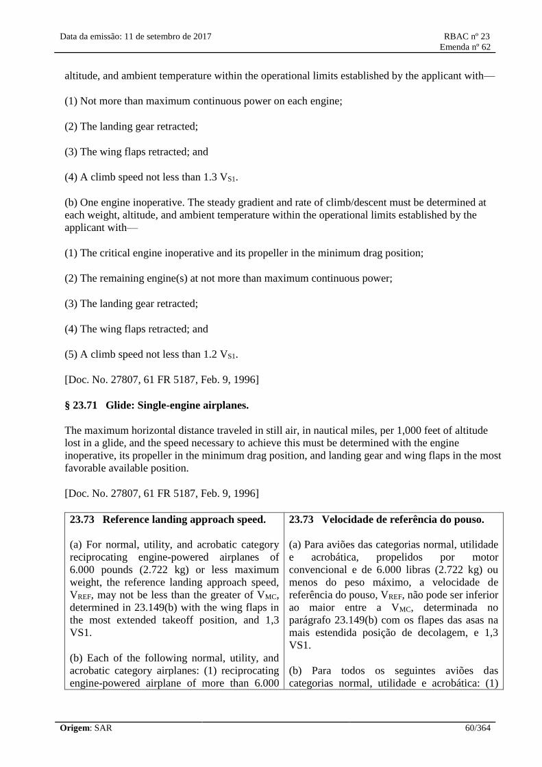
Data da emissão: 11 de setembro de 2017 RBAC nº 23
Emenda nº 62
Origem: SAR 60/364
altitude, and ambient temperature within the operational limits established by the applicant with—
(1) Not more than maximum continuous power on each engine;
(2) The landing gear retracted;
(3) The wing flaps retracted; and
(4) A climb speed not less than 1.3 VS1.
(b) One engine inoperative. The steady gradient and rate of climb/descent must be determined at
each weight, altitude, and ambient temperature within the operational limits established by the
applicant with—
(1) The critical engine inoperative and its propeller in the minimum drag position;
(2) The remaining engine(s) at not more than maximum continuous power;
(3) The landing gear retracted;
(4) The wing flaps retracted; and
(5) A climb speed not less than 1.2 VS1.
[Doc. No. 27807, 61 FR 5187, Feb. 9, 1996]
§ 23.71 Glide: Single-engine airplanes.
The maximum horizontal distance traveled in still air, in nautical miles, per 1,000 feet of altitude
lost in a glide, and the speed necessary to achieve this must be determined with the engine
inoperative, its propeller in the minimum drag position, and landing gear and wing flaps in the most
favorable available position.
[Doc. No. 27807, 61 FR 5187, Feb. 9, 1996]
23.73 Reference landing approach speed.
(a) For normal, utility, and acrobatic category
reciprocating engine-powered airplanes of
6.000 pounds (2.722 kg) or less maximum
weight, the reference landing approach speed,
VREF, may not be less than the greater of VMC,
determined in 23.149(b) with the wing flaps in
the most extended takeoff position, and 1,3
VS1.
(b) Each of the following normal, utility, and
acrobatic category airplanes: (1) reciprocating
engine-powered airplane of more than 6.000
23.73 Velocidade de referência do pouso.
(a) Para aviões das categorias normal, utilidade
e acrobática, propelidos por motor
convencional e de 6.000 libras (2.722 kg) ou
menos do peso máximo, a velocidade de
referência do pouso, VREF, não pode ser inferior
ao maior entre a VMC, determinada no
parágrafo 23.149(b) com os flapes das asas na
mais estendida posição de decolagem, e 1,3
VS1.
(b) Para todos os seguintes aviões das
categorias normal, utilidade e acrobática: (1)
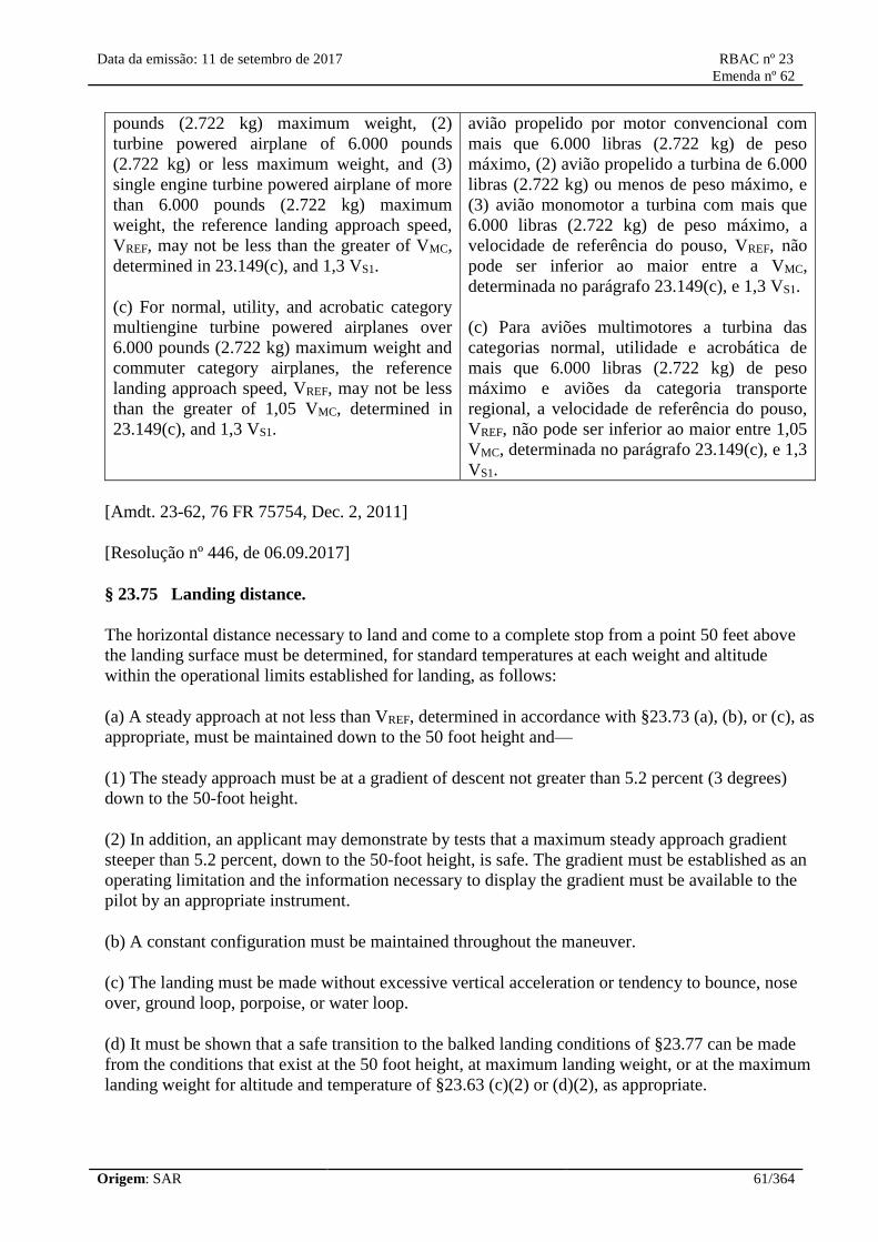
Data da emissão: 11 de setembro de 2017 RBAC nº 23
Emenda nº 62
Origem: SAR 61/364
pounds (2.722 kg) maximum weight, (2)
turbine powered airplane of 6.000 pounds
(2.722 kg) or less maximum weight, and (3)
single engine turbine powered airplane of more
than 6.000 pounds (2.722 kg) maximum
weight, the reference landing approach speed,
VREF, may not be less than the greater of VMC,
determined in 23.149(c), and 1,3 VS1.
(c) For normal, utility, and acrobatic category
multiengine turbine powered airplanes over
6.000 pounds (2.722 kg) maximum weight and
commuter category airplanes, the reference
landing approach speed, VREF, may not be less
than the greater of 1,05 VMC, determined in
23.149(c), and 1,3 VS1.
avião propelido por motor convencional com
mais que 6.000 libras (2.722 kg) de peso
máximo, (2) avião propelido a turbina de 6.000
libras (2.722 kg) ou menos de peso máximo, e
(3) avião monomotor a turbina com mais que
6.000 libras (2.722 kg) de peso máximo, a
velocidade de referência do pouso, VREF, não
pode ser inferior ao maior entre a VMC,
determinada no parágrafo 23.149(c), e 1,3 VS1.
(c) Para aviões multimotores a turbina das
categorias normal, utilidade e acrobática de
mais que 6.000 libras (2.722 kg) de peso
máximo e aviões da categoria transporte
regional, a velocidade de referência do pouso,
VREF, não pode ser inferior ao maior entre 1,05
VMC, determinada no parágrafo 23.149(c), e 1,3
VS1.
[Amdt. 23-62, 76 FR 75754, Dec. 2, 2011]
[Resolução nº 446, de 06.09.2017]
§ 23.75 Landing distance.
The horizontal distance necessary to land and come to a complete stop from a point 50 feet above
the landing surface must be determined, for standard temperatures at each weight and altitude
within the operational limits established for landing, as follows:
(a) A steady approach at not less than VREF, determined in accordance with §23.73 (a), (b), or (c), as
appropriate, must be maintained down to the 50 foot height and—
(1) The steady approach must be at a gradient of descent not greater than 5.2 percent (3 degrees)
down to the 50-foot height.
(2) In addition, an applicant may demonstrate by tests that a maximum steady approach gradient
steeper than 5.2 percent, down to the 50-foot height, is safe. The gradient must be established as an
operating limitation and the information necessary to display the gradient must be available to the
pilot by an appropriate instrument.
(b) A constant configuration must be maintained throughout the maneuver.
(c) The landing must be made without excessive vertical acceleration or tendency to bounce, nose
over, ground loop, porpoise, or water loop.
(d) It must be shown that a safe transition to the balked landing conditions of §23.77 can be made
from the conditions that exist at the 50 foot height, at maximum landing weight, or at the maximum
landing weight for altitude and temperature of §23.63 (c)(2) or (d)(2), as appropriate.

Data da emissão: 11 de setembro de 2017 RBAC nº 23
Emenda nº 62
Origem: SAR 62/364
(e) The brakes must be used so as to not cause excessive wear of brakes or tires.
(f) Retardation means other than wheel brakes may be used if that means—
(1) Is safe and reliable; and
(2) Is used so that consistent results can be expected in service.
(g) If any device is used that depends on the operation of any engine, and the landing distance
would be increased when a landing is made with that engine inoperative, the landing distance must
be determined with that engine inoperative unless the use of other compensating means will result
in a landing distance not more than that with each engine operating.
[Amdt. 23–21, 43 FR 2318, Jan. 16, 1978, as amended by Amdt. 23–34, 52 FR 1828, Jan. 15, 1987;
Amdt. 23–42, 56 FR 351, Jan. 3, 1991; Amdt. 23–50, 61 FR 5187, Feb. 9, 1996]
23.77 Balked landing.
(a) Each normal, utility, and acrobatic category
reciprocating engine-powered airplane at 6.000
pounds (2.722 kg) or less maximum weight
must be able to maintain a steady gradient of
climb at sea level of at least 3,3 percent with:
(1) Takeoff power on each engine;
(2) The landing gear extended;
(3) The wing flaps in the landing position,
except that if the flaps may safely be retracted
in two seconds or less without loss of altitude
and without sudden changes of angle of attack,
they may be retracted; and
(4) A climb speed equal to VREF, as defined in
paragraph 23.73(a).
(b) Each of the following normal, utility, and
acrobatic category airplanes: (1) reciprocating
engine-powered airplane of more than 6.000
pounds (2.722 kg) maximum weight, (2)
turbine powered airplane of 6.000 pounds
(2.722 kg) or less maximum weight, and (3)
single engine turbine powered airplane of more
than 6.000 pounds (2.722 kg) maximum
weight, must be able to maintain a steady
gradient of climb of at least 2,5 percent with:
(1) Not more than the power that is available
23.77 Arremetida.
(a) Todo avião da categoria normal, utilidade e
acrobática, propelidos por motor convencional
e de 6.000 libras (2.722 kg) ou menos de peso
máximo deve ser capaz de manter um gradiente
de subida estabilizado, ao nível do mar, de pelo
menos 3,3 por cento com:
(1) Potência de decolagem em cada motor;
(2) O trem de pouso estendido;
(3) Os flapes das asas na posição de pouso,
exceto que se os flaps puderem ser recolhidos
em segurança em dois segundos ou menos, sem
perda de altitude e sem mudanças bruscas de
ângulo de ataque, eles podem ser recolhidos; e
(4) Uma velocidade de subida igual a VREF, tal
como definido no parágrafo 23.73(a).
(b) Todos os seguintes aviões das categorias
normal, utilidade e acrobática: (1) avião
propelido por motor convencional de mais que
6.000 libras (2.722 kg) de peso máximo, (2)
avião propelido a turbina com 6.000 libras
(2.722 kg) ou menos de peso máximo, e (3)
avião monomotor a turbina com mais de 6.000
libras (2.722 kg) de peso máximo, devem ser
capazes de manter um gradiente de subida
estabilizado de pelo menos 2,5 por cento com:
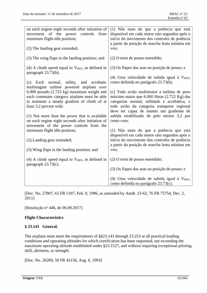
Data da emissão: 11 de setembro de 2017 RBAC nº 23
Emenda nº 62
Origem: SAR 63/364
on each engine eight seconds after initiation of
movement of the power controls from
minimum flight-idle position;
(2) The landing gear extended;
(3) The wing flaps in the landing position; and
(4) A climb speed equal to VREF, as defined in
paragraph 23.73(b).
(c) Each normal, utility, and acrobatic
multiengine turbine powered airplane over
6.000 pounds (2.722 kg) maximum weight and
each commuter category airplane must be able
to maintain a steady gradient of climb of at
least 3,2 percent with:
(1) Not more than the power that is available
on each engine eight seconds after initiation of
movement of the power controls from the
minimum flight idle position;
(2) Landing gear extended;
(3) Wing flaps in the landing position; and
(4) A climb speed equal to VREF, as defined in
paragraph 23.73(c).
(1) Não mais do que a potência que está
disponível em cada motor oito segundos após o
início do movimento dos controles de potência
a partir da posição de marcha lenta mínima em
voo;
(2) O trem de pouso estendido;
(3) Os flapes das asas na posição de pouso; e
(4) Uma velocidade de subida igual à VREF,
como definida no parágrafo 23.73(b).
(c) Todo avião multimotor a turbina de peso
máximo maior que 6.000 libras (2.722 Kg) das
categorias normal, utilidade e acrobática, e
todo avião da categoria transporte regional
deve ser capaz de manter um gradiente de
subida estabilizado de pelo menos 3,2 por
cento com:
(1) Não mais do que a potência que está
disponível em cada motor oito segundos após o
início do movimento dos controles de potência
a partir da posição de marcha lenta mínima em
voo;
(2) O trem de pouso estendido;
(3) Os flapes das asas na posição de pouso; e
(4) Uma velocidade de subida igual à VREF,
como definida no parágrafo 23.73(c).
[Doc. No. 27807, 61 FR 5187, Feb. 9, 1996, as amended by Amdt. 23-62, 76 FR 75754, Dec. 2,
2011]
[Resolução nº 446, de 06.09.2017]
Flight Characteristics
§ 23.141 General.
The airplane must meet the requirements of §§23.143 through 23.253 at all practical loading
conditions and operating altitudes for which certification has been requested, not exceeding the
maximum operating altitude established under §23.1527, and without requiring exceptional piloting
skill, alertness, or strength.
[Doc. No. 26269, 58 FR 42156, Aug. 6, 1993]

Data da emissão: 11 de setembro de 2017 RBAC nº 23
Emenda nº 62
Origem: SAR 64/364
Controllability and Maneuverability
§ 23.143 General.
(a) The airplane must be safely controllable and maneuverable during all flight phases including—
(1) Takeoff;
(2) Climb;
(3) Level flight;
(4) Descent;
(5) Go-around; and
(6) Landing (power on and power off) with the wing flaps extended and retracted.
(b) It must be possible to make a smooth transition from one flight condition to another (including
turns and slips) without danger of exceeding the limit load factor, under any probable operating
condition (including, for multiengine airplanes, those conditions normally encountered in the
sudden failure of any engine).
(c) If marginal conditions exist with regard to required pilot strength, the control forces necessary
must be determined by quantitative tests. In no case may the control forces under the conditions
specified in paragraphs (a) and (b) of this section exceed those prescribed in the following table:
Values in pounds force applied to the relevant control Pitch Roll Yaw
(a) For temporary application:
Stick 60 30
Wheel (Two hands on rim) 75 50
Wheel (One hand on rim) 50 25
Rudder Pedal 150
(b) For prolonged application 10 5 20
[Doc. No, 4080, 29 FR 17955, Dec. 18, 1964, as amended by Amdt. 23–14, 38 FR 31819, Nov. 19,
1973; Amdt. 23–17, 41 FR 55464, Dec. 20, 1976; Amdt. 23–45, 58 FR 42156, Aug. 6, 1993; Amdt.
23–50, 61 FR 5188, Feb. 9, 1996]
§ 23.145 Longitudinal control.
(a) With the airplane as nearly as possible in trim at 1.3 VS1, it must be possible, at speeds below the
trim speed, to pitch the nose downward so that the rate of increase in airspeed allows prompt
acceleration to the trim speed with—
(1) Maximum continuous power on each engine;

Data da emissão: 11 de setembro de 2017 RBAC nº 23
Emenda nº 62
Origem: SAR 65/364
(2) Power off; and
(3) Wing flap and landing gear—
(i) retracted, and
(ii) extended.
(b) Unless otherwise required, it must be possible to carry out the following maneuvers without
requiring the application of single-handed control forces exceeding those specified in §23.143(c).
The trimming controls must not be adjusted during the maneuvers:
(1) With the landing gear extended, the flaps retracted, and the airplanes as nearly as possible in
trim at 1.4 VS1, extend the flaps as rapidly as possible and allow the airspeed to transition from
1.4VS1to 1.4 VSO:
(i) With power off; and
(ii) With the power necessary to maintain level flight in the initial condition.
(2) With landing gear and flaps extended, power off, and the airplane as nearly as possible in trim at
1.3 VSO: quickly apply takeoff power and retract the flaps as rapidly as possible to the
recommended go around setting and allow the airspeed to transition from 1.3 VSOto 1.3 VS1. Retract
the gear when a positive rate of climb is established.
(3) With landing gear and flaps extended, in level flight, power necessary to attain level flight at 1.1
VSO, and the airplane as nearly as possible in trim, it must be possible to maintain approximately
level flight while retracting the flaps as rapidly as possible with simultaneous application of not
more than maximum continuous power. If gated flat positions are provided, the flap retraction may
be demonstrated in stages with power and trim reset for level flight at 1.1 VS1, in the initial
configuration for each stage—
(i) From the fully extended position to the most extended gated position;
(ii) Between intermediate gated positions, if applicable; and
(iii) From the least extended gated position to the fully retracted position.
(4) With power off, flaps and landing gear retracted and the airplane as nearly as possible in trim at
1.4 VS1, apply takeoff power rapidly while maintaining the same airspeed.
(5) With power off, landing gear and flaps extended, and the airplane as nearly as possible in trim at
VREF, obtain and maintain airspeeds between 1.1 VSO, and either 1.7 VSOor VFE, whichever is lower
without requiring the application of two-handed control forces exceeding those specified in
§23.143(c).
(6) With maximum takeoff power, landing gear retracted, flaps in the takeoff position, and the
airplane as nearly as possible in trim at VFEappropriate to the takeoff flap position, retract the flaps
as rapidly as possible while maintaining constant speed.

Data da emissão: 11 de setembro de 2017 RBAC nº 23
Emenda nº 62
Origem: SAR 66/364
(c) At speeds above VMO/MMO, and up to the maximum speed shown under §23.251, a maneuvering
capability of 1.5 g must be demonstrated to provide a margin to recover from upset or inadvertent
speed increase.
(d) It must be possible, with a pilot control force of not more than 10 pounds, to maintain a speed of
not more than VREFduring a power-off glide with landing gear and wing flaps extended, for any
weight of the airplane, up to and including the maximum weight.
(e) By using normal flight and power controls, except as otherwise noted in paragraphs (e)(1) and
(e)(2) of this section, it must be possible to establish a zero rate of descent at an attitude suitable for
a controlled landing without exceeding the operational and structural limitations of the airplane, as
follows:
(1) For single-engine and multiengine airplanes, without the use of the primary longitudinal control
system.
(2) For multiengine airplanes—
(i) Without the use of the primary directional control; and
(ii) If a single failure of any one connecting or transmitting link would affect both the longitudinal
and directional primary control system, without the primary longitudinal and directional control
system.
[Doc. No. 26269, 58 FR 42157, Aug. 6, 1993; Amdt. 23–45, 58 FR 51970, Oct. 5, 1993, as
amended by Amdt. 23–50, 61 FR 5188, Feb. 9, 1996]
§ 23.147 Directional and lateral control.
(a) For each multiengine airplane, it must be possible, while holding the wings level within five
degrees, to make sudden changes in heading safely in both directions. This ability must be shown at
1.4 VS1with heading changes up to 15 degrees, except that the heading change at which the rudder
force corresponds to the limits specified in §23.143 need not be exceeded, with the—
(1) Critical engine inoperative and its propeller in the minimum drag position;
(2) Remaining engines at maximum continuous power;
(3) Landing gear—
(i) Retracted; and
(ii) Extended; and
(4) Flaps retracted.
(b) For each multiengine airplane, it must be possible to regain full control of the airplane without
exceeding a bank angle of 45 degrees, reaching a dangerous attitude or encountering dangerous
characteristics, in the event of a sudden and complete failure of the critical engine, making

Data da emissão: 11 de setembro de 2017 RBAC nº 23
Emenda nº 62
Origem: SAR 67/364
allowance for a delay of two seconds in the initiation of recovery action appropriate to the situation,
with the airplane initially in trim, in the following condition:
(1) Maximum continuous power on each engine;
(2) The wing flaps retracted;
(3) The landing gear retracted;
(4) A speed equal to that at which compliance with §23.69(a) has been shown; and
(5) All propeller controls in the position at which compliance with §23.69(a) has been shown.
(c) For all airplanes, it must be shown that the airplane is safely controllable without the use of the
primary lateral control system in any all-engine configuration(s) and at any speed or altitude within
the approved operating envelope. It must also be shown that the airplane's flight characteristics are
not impaired below a level needed to permit continued safe flight and the ability to maintain
attitudes suitable for a controlled landing without exceeding the operational and structural
limitations of the airplane. If a single failure of any one connecting or transmitting link in the lateral
control system would also cause the loss of additional control system(s), compliance with the above
requirement must be shown with those additional systems also assumed to be inoperative.
[Doc. No. 27807, 61 FR 5188, Feb. 9, 1996]
§ 23.149 Minimum control speed.
(a) VMCis the calibrated airspeed at which, when the critical engine is suddenly made inoperative, it
is possible to maintain control of the airplane with that engine still inoperative, and thereafter
maintain straight flight at the same speed with an angle of bank of not more than 5 degrees. The
method used to simulate critical engine failure must represent the most critical mode of powerplant
failure expected in service with respect to controllability.
(b) VMCfor takeoff must not exceed 1.2 VS1, where VS1is determined at the maximum takeoff
weight. VMCmust be determined with the most unfavorable weight and center of gravity position
and with the airplane airborne and the ground effect negligible, for the takeoff configuration(s)
with—
(1) Maximum available takeoff power initially on each engine;
(2) The airplane trimmed for takeoff;
(3) Flaps in the takeoff position(s);
(4) Landing gear retracted; and
(5) All propeller controls in the recommended takeoff position throughout.
(c) For all airplanes except reciprocating engine-powered airplanes of 6,000 pounds or less
maximum weight, the conditions of paragraph (a) of this section must also be met for the landing

Data da emissão: 11 de setembro de 2017 RBAC nº 23
Emenda nº 62
Origem: SAR 68/364
configuration with—
(1) Maximum available takeoff power initially on each engine;
(2) The airplane trimmed for an approach, with all engines operating, at VREF, at an approach
gradient equal to the steepest used in the landing distance demonstration of §23.75;
(3) Flaps in the landing position;
(4) Landing gear extended; and
(5) All propeller controls in the position recommended for approach with all engines operating.
(d) A minimum speed to intentionally render the critical engine inoperative must be established and
designated as the safe, intentional, one-engine-inoperative speed, VSSE.
(e) At VMC, the rudder pedal force required to maintain control must not exceed 150 pounds and it
must not be necessary to reduce power of the operative engine(s). During the maneuver, the
airplane must not assume any dangerous attitude and it must be possible to prevent a heading
change of more than 20 degrees.
(f) At the option of the applicant, to comply with the requirements of §23.51(c)(1), VMCGmay be
determined. VMCGis the minimum control speed on the ground, and is the calibrated airspeed during
the takeoff run at which, when the critical engine is suddenly made inoperative, it is possible to
maintain control of the airplane using the rudder control alone (without the use of nosewheel
steering), as limited by 150 pounds of force, and using the lateral control to the extent of keeping
the wings level to enable the takeoff to be safely continued. In the determination of VMCG, assuming
that the path of the airplane accelerating with all engines operating is along the centerline of the
runway, its path from the point at which the critical engine is made inoperative to the point at which
recovery to a direction parallel to the centerline is completed may not deviate more than 30 feet
laterally from the centerline at any point. VMCGmust be established with—
(1) The airplane in each takeoff configuration or, at the option of the applicant, in the most critical
takeoff configuration;
(2) Maximum available takeoff power on the operating engines;
(3) The most unfavorable center of gravity;
(4) The airplane trimmed for takeoff; and
(5) The most unfavorable weight in the range of takeoff weights.
[Doc. No. 27807, 61 FR 5189, Feb. 9, 1996]
§ 23.151 Acrobatic maneuvers.
Each acrobatic and utility category airplane must be able to perform safely the acrobatic maneuvers
for which certification is requested. Safe entry speeds for these maneuvers must be determined.

Data da emissão: 11 de setembro de 2017 RBAC nº 23
Emenda nº 62
Origem: SAR 69/364
§ 23.153 Control during landings.
It must be possible, while in the landing configuration, to safely complete a landing without
exceeding the one-hand control force limits specified in §23.143(c) following an approach to land—
(a) At a speed of VREFminus 5 knots;
(b) With the airplane in trim, or as nearly as possible in trim and without the trimming control being
moved throughout the maneuver;
(c) At an approach gradient equal to the steepest used in the landing distance demonstration of
§23.75; and
(d) With only those power changes, if any, that would be made when landing normally from an
approach at VREF.
[Doc. No. 27807, 61 FR 5189, Feb. 9, 1996]
§ 23.155 Elevator control force in maneuvers.
(a) The elevator control force needed to achieve the positive limit maneuvering load factor may not
be less than:
(1) For wheel controls, W/100 (where W is the maximum weight) or 20 pounds, whichever is
greater, except that it need not be greater than 50 pounds; or
(2) For stick controls, W/140 (where W is the maximum weight) or 15 pounds, whichever is
greater, except that it need not be greater than 35 pounds.
(b) The requirement of paragraph (a) of this section must be met at 75 percent of maximum
continuous power for reciprocating engines, or the maximum continuous power for turbine engines,
and with the wing flaps and landing gear retracted—
(1) In a turn, with the trim setting used for wings level flight at VO; and
(2) In a turn with the trim setting used for the maximum wings level flight speed, except that the
speed may not exceed VNEor VMO/MMO, whichever is appropriate.
(c) There must be no excessive decrease in the gradient of the curve of stick force versus
maneuvering load factor with increasing load factor.
[Amdt. 23–14, 38 FR 31819, Nov. 19, 1973; 38 FR 32784, Nov. 28, 1973, as amended by Amdt.
23–45, 58 FR 42158, Aug. 6, 1993; Amdt. 23–50, 61 FR 5189 Feb. 9, 1996]
§ 23.157 Rate of roll.
(a) Takeoff. It must be possible, using a favorable combination of controls, to roll the airplane from
a steady 30-degree banked turn through an angle of 60 degrees, so as to reverse the direction of the
turn within:

Data da emissão: 11 de setembro de 2017 RBAC nº 23
Emenda nº 62
Origem: SAR 70/364
(1) For an airplane of 6,000 pounds or less maximum weight, 5 seconds from initiation of roll; and
(2) For an airplane of over 6,000 pounds maximum weight,
(W+500)/1,300
seconds, but not more than 10 seconds, where W is the weight in pounds.
(b) The requirement of paragraph (a) of this section must be met when rolling the airplane in each
direction with—
(1) Flaps in the takeoff position;
(2) Landing gear retracted;
(3) For a single-engine airplane, at maximum takeoff power; and for a multiengine airplane with the
critical engine inoperative and the propeller in the minimum drag position, and the other engines at
maximum takeoff power; and
(4) The airplane trimmed at a speed equal to the greater of 1.2 VS1or 1.1 VMC, or as nearly as
possible in trim for straight flight.
(c) Approach. It must be possible, using a favorable combination of controls, to roll the airplane
from a steady 30-degree banked turn through an angle of 60 degrees, so as to reverse the direction
of the turn within:
(1) For an airplane of 6,000 pounds or less maximum weight, 4 seconds from initiation of roll; and
(2) For an airplane of over 6,000 pounds maximum weight,
(W+2,800)/2,200
seconds, but not more than 7 seconds, where W is the weight in pounds.
(d) The requirement of paragraph (c) of this section must be met when rolling the airplane in each
direction in the following conditions—
(1) Flaps in the landing position(s);
(2) Landing gear extended;
(3) All engines operating at the power for a 3 degree approach; and
(4) The airplane trimmed at VREF.
[Amdt. 23–14, 38 FR 31819, Nov. 19, 1973, as amended by Amdt. 23–45, 58 FR 42158, Aug. 6,
1993; Amdt. 23–50, 61 FR 5189, Feb. 9, 1996]
Trim

Data da emissão: 11 de setembro de 2017 RBAC nº 23
Emenda nº 62
Origem: SAR 71/364
23.161 Trim.
(a) General. Each airplane must meet the trim
requirements of this section after being
trimmed and without further pressure upon, or
movement of, the primary controls or their
corresponding trim controls by the pilot or the
automatic pilot. In addition, it must be possible,
in other conditions of loading, configuration,
speed and power to ensure that the pilot will
not be unduly fatigued or distracted by the need
to apply residual control forces exceeding those
for prolonged application of paragraph
23.143(c). This applies in normal operation of
the airplane and, if applicable, to those
conditions associated with the failure of one
engine for which performance characteristics
are established.
(b) Lateral and directional trim. The airplane
must maintain lateral and directional trim in
level flight with the landing gear and wing
flaps retracted as follows:
(1) For normal, utility, and acrobatic category
airplanes, at a speed of 0,9 VH, VC, or
VMO/MMO, whichever is lowest; and
(2) For commuter category airplanes, at all
speeds from 1,4 VS1 to the lesser of VH or
VMO/MMO.
(c) Longitudinal trim. The airplane must
maintain longitudinal trim under each of the
following conditions:
(1) A climb with:
(i) Takeoff power, landing gear retracted, wing
flaps in the takeoff position(s), at the speeds
used in determining the climb performance
required by section 23.65; and
(ii) Maximum continuous power at the speeds
and in the configuration used in determining
the climb performance required by paragraph
23.69(a).
(2) Level flight at all speeds from the lesser of
23.161 Compensação.
(a) Geral. Cada avião deve cumprir os
requisitos de compensação desta seção depois
de ser compensado e sem nenhuma pressão ou
movimento adicionais nos controles primários
ou seus controles de compensação
correspondentes pelo piloto ou pelo piloto
automático. Além disso, deve ser possível, em
outras condições de carregamento,
configuração, velocidade e potência garantir
que o piloto não seja excessivamente fatigado
ou distraído pela necessidade de aplicar forças
de controle residuais que excedam aquelas
prescritas para aplicação prolongada de acordo
com o parágrafo 23.143 (c). Isso se aplica à
operação normal do avião, e se aplicável, para
aquelas condições associadas à falha de um
motor para as quais as características de
desempenho são estabelecidas.
(b) Compensação lateral e direcional. O avião
deve manter compensação lateral e direcional
em voo nivelado com o trem de pouso e flapes
das asas recolhidos conforme segue:
(1) Para aviões das categorias normal, utilidade
e acrobática, na velocidade de 0,9 VH, VC ou
VMO/MMO, o que for menor, e;
(2) Para aviões da categoria transporte regional,
em todas as velocidades a partir de 1.4 VS1 até
a menor entre VH ou VMO/MMO.
(c) Compensação longitudinal. O avião deve
manter compensação longitudinal sob cada
uma das seguintes condições:
(1) Uma subida com:
(i) Potência de decolagem, trem de pouso
recolhido, flapes das asas na(s) posição(ões) de
decolagem, nas velocidades usadas para
determinar o desempenho de subida requerido
pela seção 23.65; e
(ii) Máxima potência contínua nas velocidades
e configuração usadas para determinar o
desempenho de subida requerido pelo
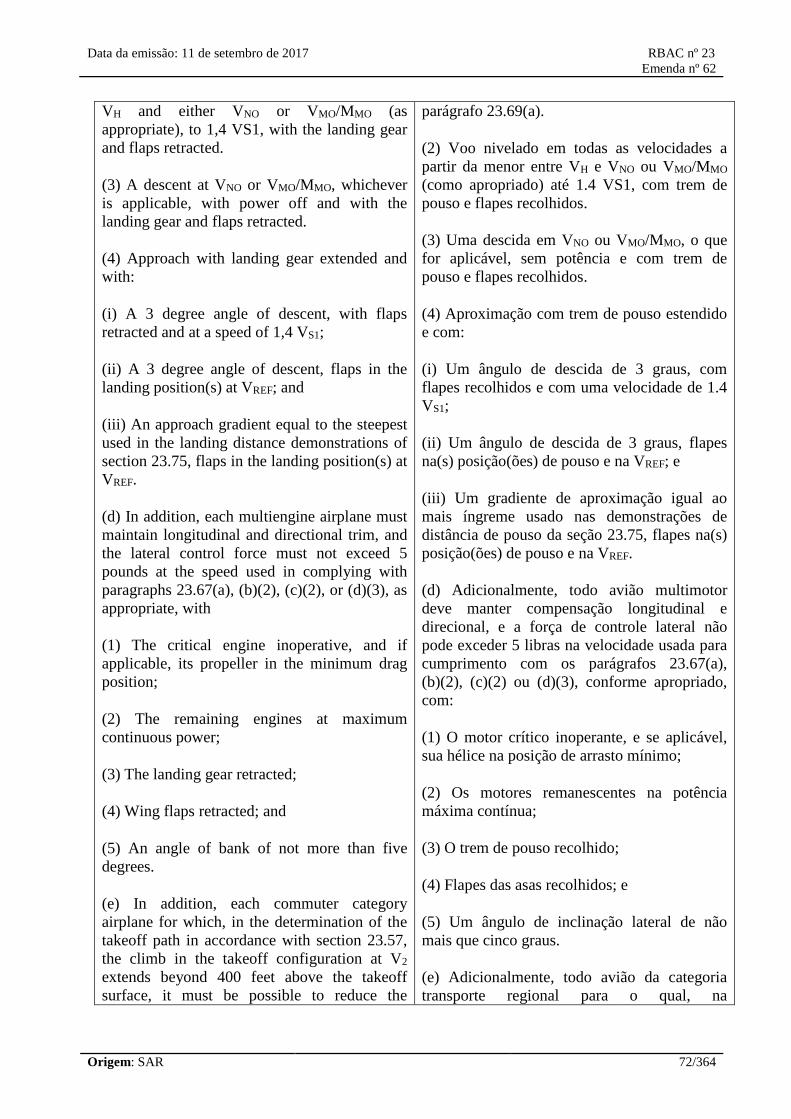
Data da emissão: 11 de setembro de 2017 RBAC nº 23
Emenda nº 62
Origem: SAR 72/364
VH and either VNO or VMO/MMO (as
appropriate), to 1,4 VS1, with the landing gear
and flaps retracted.
(3) A descent at VNO or VMO/MMO, whichever
is applicable, with power off and with the
landing gear and flaps retracted.
(4) Approach with landing gear extended and
with:
(i) A 3 degree angle of descent, with flaps
retracted and at a speed of 1,4 VS1;
(ii) A 3 degree angle of descent, flaps in the
landing position(s) at VREF; and
(iii) An approach gradient equal to the steepest
used in the landing distance demonstrations of
section 23.75, flaps in the landing position(s) at
VREF.
(d) In addition, each multiengine airplane must
maintain longitudinal and directional trim, and
the lateral control force must not exceed 5
pounds at the speed used in complying with
paragraphs 23.67(a), (b)(2), (c)(2), or (d)(3), as
appropriate, with
(1) The critical engine inoperative, and if
applicable, its propeller in the minimum drag
position;
(2) The remaining engines at maximum
continuous power;
(3) The landing gear retracted;
(4) Wing flaps retracted; and
(5) An angle of bank of not more than five
degrees.
(e) In addition, each commuter category
airplane for which, in the determination of the
takeoff path in accordance with section 23.57,
the climb in the takeoff configuration at V2
extends beyond 400 feet above the takeoff
surface, it must be possible to reduce the
parágrafo 23.69(a).
(2) Voo nivelado em todas as velocidades a
partir da menor entre VH e VNO ou VMO/MMO
(como apropriado) até 1.4 VS1, com trem de
pouso e flapes recolhidos.
(3) Uma descida em VNO ou VMO/MMO, o que
for aplicável, sem potência e com trem de
pouso e flapes recolhidos.
(4) Aproximação com trem de pouso estendido
e com:
(i) Um ângulo de descida de 3 graus, com
flapes recolhidos e com uma velocidade de 1.4
VS1;
(ii) Um ângulo de descida de 3 graus, flapes
na(s) posição(ões) de pouso e na VREF; e
(iii) Um gradiente de aproximação igual ao
mais íngreme usado nas demonstrações de
distância de pouso da seção 23.75, flapes na(s)
posição(ões) de pouso e na VREF.
(d) Adicionalmente, todo avião multimotor
deve manter compensação longitudinal e
direcional, e a força de controle lateral não
pode exceder 5 libras na velocidade usada para
cumprimento com os parágrafos 23.67(a),
(b)(2), (c)(2) ou (d)(3), conforme apropriado,
com:
(1) O motor crítico inoperante, e se aplicável,
sua hélice na posição de arrasto mínimo;
(2) Os motores remanescentes na potência
máxima contínua;
(3) O trem de pouso recolhido;
(4) Flapes das asas recolhidos; e
(5) Um ângulo de inclinação lateral de não
mais que cinco graus.
(e) Adicionalmente, todo avião da categoria
transporte regional para o qual, na
Data da emissão: 11 de setembro de 2017 RBAC nº 23
Emenda nº 62
Origem: SAR 73/364
longitudinal and lateral control forces to 10
pounds and 5 pounds, respectively, and the
directional control force must not exceed 50
pounds at V2 with:
(1) The critical engine inoperative and its
propeller in the minimum drag position;
(2) The remaining engine(s) at takeoff power;
(3) Landing gear retracted;
(4) Wing flaps in the takeoff position(s); and
(5) An angle of bank not exceeding 5 degrees.
determinação da trajetória de decolagem de
acordo com a seção 23.57, a subida na
configuração de decolagem na V2 se estenda
além de 400 pés acima da superfície de
decolagem, deve ser possível reduzir as forças
nos controles longitudinal e lateral para 10
libras e 5 libras, respectivamente, e a força no
controle direcional não pode exceder 50 libras
na V2 com:
(1) O motor crítico inoperante e sua hélice na
posição de arrasto mínimo;
(2) O(s) motor(es) remanescente(s) em
potência de decolagem;
(3) O trem de pouso recolhido;
(4) Os flapes das asas na(s) posição(ões) de
decolagem; e
(5) Um ângulo de inclinação lateral que não
exceda 5 graus.
[Doc. No. 4080, 29 FR 17955, Dec. 18, 1964, as amended by Amdt. 23-21, 43 FR 2318, Jan. 16,
1978; Amdt. 23-34, 52 FR 1828, Jan. 15, 1987; Amdt. 23-42, 56 FR 351, Jan. 3, 1991; 56 FR 5455,
Feb. 11, 1991; Amdt. 23-50, 61 FR 5189, Feb. 9, 1996]
[Resolução nº 446, de 06.09.2017]
Stability
§ 23.171 General.
The airplane must be longitudinally, directionally, and laterally stable under §§23.173 through
23.181. In addition, the airplane must show suitable stability and control “feel” (static stability) in
any condition normally encountered in service, if flight tests show it is necessary for safe operation.
§ 23.173 Static longitudinal stability.
Under the conditions specified in §23.175 and with the airplane trimmed as indicated, the
characteristics of the elevator control forces and the friction within the control system must be as
follows:
(a) A pull must be required to obtain and maintain speeds below the specified trim speed and a push
required to obtain and maintain speeds above the specified trim speed. This must be shown at any
speed that can be obtained, except that speeds requiring a control force in excess of 40 pounds or
speeds above the maximum allowable speed or below the minimum speed for steady unstalled
flight, need not be considered.

Data da emissão: 11 de setembro de 2017 RBAC nº 23
Emenda nº 62
Origem: SAR 74/364
(b) The airspeed must return to within the tolerances specified for applicable categories of airplanes
when the control force is slowly released at any speed within the speed range specified in paragraph
(a) of this section. The applicable tolerances are—
(1) The airspeed must return to within plus or minus 10 percent of the original trim airspeed; and
(2) For commuter category airplanes, the airspeed must return to within plus or minus 7.5 percent of
the original trim airspeed for the cruising condition specified in §23.175(b).
(c) The stick force must vary with speed so that any substantial speed change results in a stick force
clearly perceptible to the pilot.
[Doc. No. 4080, 29 FR 17955, Dec. 18, 1964, as amended by Amdt. 23–14, 38 FR 31820 Nov. 19,
1973; Amdt. 23–34, 52 FR 1828, Jan. 15, 1987]
§ 23.175 Demonstration of static longitudinal stability.
Static longitudinal stability must be shown as follows:
(a) Climb. The stick force curve must have a stable slope at speeds between 85 and 115 percent of
the trim speed, with—
(1) Flaps retracted;
(2) Landing gear retracted;
(3) Maximum continuous power; and
(4) The airplane trimmed at the speed used in determining the climb performance required by
§23.69(a).
(b) Cruise. With flaps and landing gear retracted and the airplane in trim with power for level flight
at representative cruising speeds at high and low altitudes, including speeds up to VNOor VMO/MMO,
as appropriate, except that the speed need not exceed VH—
(1) For normal, utility, and acrobatic category airplanes, the stick force curve must have a stable
slope at all speeds within a range that is the greater of 15 percent of the trim speed plus the resulting
free return speed range, or 40 knots plus the resulting free return speed range, above and below the
trim speed, except that the slope need not be stable—
(i) At speeds less than 1.3 VS1; or
(ii) For airplanes with VNEestablished under §23.1505(a), at speeds greater than VNE; or
(iii) For airplanes with VMO/MMOestablished under §23.1505(c), at speeds greater than VFC/MFC.
(2) For commuter category airplanes, the stick force curve must have a stable slope at all speeds
within a range of 50 knots plus the resulting free return speed range, above and below the trim
speed, except that the slope need not be stable—
Data da emissão: 11 de setembro de 2017 RBAC nº 23
Emenda nº 62
Origem: SAR 75/364
(i) At speeds less than 1.4 VS1; or
(ii) At speeds greater than VFC/MFC; or
(iii) At speeds that require a stick force greater than 50 pounds.
(c) Landing. The stick force curve must have a stable slope at speeds between 1.1 VS1and 1.8
VS1with—
(1) Flaps in the landing position;
(2) Landing gear extended; and
(3) The airplane trimmed at—
(i) VREF, or the minimum trim speed if higher, with power off; and
(ii) VREFwith enough power to maintain a 3 degree angle of descent.
[Doc. No. 27807, 61 FR 5190, Feb. 9, 1996]
23.177 Static directional and lateral
stability.
(a)(1) The static directional stability, as shown
by the tendency to recover from a wings level
sideslip with the rudder free, must be positive
for any landing gear and flap position
appropriate to the takeoff, climb, cruise,
approach, and landing configurations. This
must be shown with symmetrical power up to
maximum continuous power, and at speeds
from 1,2 VS1 up to VFE, VLE, VNO, VFC/MFC,
whichever is appropriate.
(2) The angle of sideslip for these tests must be
appropriate to the type of airplane. The rudder
pedal force must not reverse at larger angles of
sideslip, up to that at which full rudder is used
or a control force limit in section 23.143 is
reached, whichever occurs first, and at speeds
from 1,2 VS1 to V0.
(b)(1) The static lateral stability, as shown by
the tendency to raise the low wing in a sideslip
with the aileron controls free, may not be
negative for any landing gear and flap position
appropriate to the takeoff, climb, cruise,
approach, and landing configurations. This
23.177 Estabilidade Estática Direcional e
Lateral.
(a)(1) A estabilidade estática direcional,
verificada pela tendência de recuperação de
uma derrapagem com asa nivelada com o leme
livre, deve ser positiva para qualquer posição
de trem de pouso e flapes apropriada para as
configurações de decolagem, subida, cruzeiro,
aproximação e pouso. Isso deve ser
demonstrado com potência simétrica até a
potência máxima contínua e em velocidades
desde 1,2 VS1 até VFE, VLE, VNO, VFC/MFC, o
que for apropriado.
(2) O ângulo de derrapagem para estes testes
deve ser apropriado para o tipo de avião. A
força no pedal do leme não pode reverter em
ângulos de derrapagem maiores, até aquele em
que o leme todo é usado ou a força nos
controles limite da seção 23.143 é alcançada, o
que ocorrer antes, e em velocidades desde 1,2
VS1 a V0.
(b)(1) A estabilidade estática lateral, verificada
pela tendência de levantar a asa baixa em uma
derrapagem com os controles de ailerons livres,
não pode ser negativa para quaisquer posições

Data da emissão: 11 de setembro de 2017 RBAC nº 23
Emenda nº 62
Origem: SAR 76/364
must be shown with symmetrical power from
idle up to 75 percent of maximum continuous
power at speeds from 1,2 VS1 in the takeoff
configuration(s) and at speeds from 1,3 VS1 in
other configurations, up to the maximum
allowable airspeed for the configuration being
investigated (VFE, VLE, VNO, VFC/MFC,
whichever is appropriate) in the takeoff, climb,
cruise, descent, and approach configurations.
For the landing configuration, the power must
be that necessary to maintain a 3-degree angle
of descent in coordinated flight.
(2) The static lateral stability may not be
negative at 1,2 VS1 in the takeoff configuration,
or at 1,3 VS1 in other configurations.
(3) The angle of sideslip for these tests must be
appropriate to the type of airplane, but in no
case may the constant heading sideslip angle be
less than that obtainable with a 10 degree bank
or, if less, the maximum bank angle obtainable
with full rudder deflection or 150 pound rudder
force.
(c) Paragraph (b) of this section does not apply
to acrobatic category airplanes certificated for
inverted flight.
(d)(1) In straight, steady slips at 1,2 VS1 for any
landing gear and flap position appropriate to
the takeoff, climb, cruise, approach, and
landing configurations, and for any
symmetrical power conditions up to 50 percent
of maximum continuous power, the aileron and
rudder control movements and forces must
increase steadily, but not necessarily in
constant proportion, as the angle of sideslip is
increased up to the maximum appropriate to the
type of airplane.
(2) At larger slip angles, up to the angle at
which the full rudder or aileron control is used
or a control force limit contained in section
23.143 is reached, the aileron and rudder
control movements and forces may not reverse
as the angle of sideslip is increased.
(3) Rapid entry into, and recovery from, a
de trem de pouso e flapes apropriadas para as
configurações de decolagem, cruzeiro,
aproximação, e pouso. Isso deve ser
demonstrado com potência simétrica da marcha
lenta até 75 por cento da potência máxima
contínua em velocidades a partir de 1,2 VS1
na(s) configuração(ões) de decolagem e nas
velocidades a partir de 1,3 VS1 em outras
configurações, até a máxima velocidade
aerodinâmica permitida para a configuração
sendo investigada (VFE, VLE, VNO, VFC/MFC, o
que for apropriado), nas configurações de
decolagem, subida, cruzeiro, descida e
aproximação. Para a configuração de pouso, a
potência deve ser a necessária para manter um
ângulo de descida de 3 graus em voo
coordenado.
(2) A estabilidade estática lateral não pode ser
negativa em 1,2 VS1 na configuração de
decolagem, ou em 1,3 VS1 em outras
configurações.
(3) O ângulo de derrapagem para estes testes
deve ser apropriado para o tipo de avião, mas
em nenhum caso o ângulo de derrapagem com
proa constante deve ser inferior ao obtido com
10 graus de inclinação lateral, ou se menor, o
ângulo máximo de inclinação lateral obtido
com deflexão total do leme ou 150 libras de
força de leme.
(c) O parágrafo (b) desta seção não se aplica a
aviões de categoria acrobática certificados para
voo invertido.
(d)(1) Em derrapagens estabilizada em voo reto
a 1,2 VS1 para quaisquer posições de flapes e
trem de pouso apropriada para as configurações
de decolagem, subida, cruzeiro, aproximação, e
pouso, e para qualquer condição de potência
simétrica até 50 por cento da potência máxima
contínua, os movimentos e forças de controle
de leme e aileron devem crescer
continuamente, mas não necessariamente em
proporção constante, à medida que o ângulo de
derrapagem é aumentado até o máximo
apropriado ao tipo de avião.

Data da emissão: 11 de setembro de 2017 RBAC nº 23
Emenda nº 62
Origem: SAR 77/364
maximum sideslip considered appropriate for
the airplane may not result in uncontrollable
flight characteristics.
(2) Em ângulos de derrapagem maiores, até o
ângulo em que todo o controle de leme ou
aileron é usado ou a força de controle limite
contida na seção 23.143 é alcançada, os
movimentos e forças dos controles de leme e
aileron não podem reverter à medida que o
ângulo de derrapagem é aumentado.
(3) Uma entrada rápida, e recuperação da
máxima derrapagem considerada apropriada
para o avião não pode resultar em
características de voo incontroláveis.
[Doc. No. 27807, 61 FR 5190, Feb. 9, 1996, as amended by Amdt. 23-62, 76 FR 75754, Dec. 2,
2011]
[Resolução nº 446, de 06.09.2017]
23.181 Dynamic stability.
(a) Any short period oscillation not including
combined lateral-directional oscillations
occurring between the stalling speed and the
maximum allowable speed appropriate to the
configuration of the airplane must be heavily
damped with the primary controls:
(1) Free; and
(2) In a fixed position.
(b) Any combined lateral-directional
oscillations (Dutch roll) occurring between the
stalling speed and the maximum allowable
speed (VFE, VLE, VN0, VFC/MFC) appropriate to
the configuration of the airplane with the
primary controls in both free and fixed
position, must be damped to 1/10 amplitude in:
(1) Seven (7) cycles below 18.000 feet (5.486,4
m) and
(2) Thirteen (13) cycles from 18.000 feet
(5.486,4 m) to the certified maximum altitude.
(c) If it is determined that the function of a
stability augmentation system, reference
section 23.672, is needed to meet the flight
characteristic requirements of this part, the
23.181 Estabilidade Dinâmica.
(a) Qualquer oscilação de curto-período não
incluindo oscilações combinadas látero-
direcional que ocorram entre a velocidade de
estol e a velocidade máxima permitida
apropriada para a configuração do avião deve
ser fortemente amortecida com os controles
primários:
(1) Livres; e
(2) Numa posição fixa.
(b) Quaisquer oscilações combinadas látero-
direcional (“Dutch roll”) que ocorram entre a
velocidade de estol e a velocidade máxima
permitida (VFE, VLE, VNO, VFC/MFC) apropriada
para a configuração do avião com os controles
primários em ambas posições fixa e livre,
devem ser amortecidas a 1/10 da amplitude em:
(1) Sete (7) ciclos abaixo de 18.000 pés
(5.486,4 m) e
(2) Treze (13) ciclos de 18.000 pés (5.486,4 m)
até a máxima altitude certificada.
(c) Se for determinado que a função de um
sistema de estabilidade aumentada (vide seção
23.672) é necessária para cumprimento dos
Data da emissão: 11 de setembro de 2017 RBAC nº 23
Emenda nº 62
Origem: SAR 78/364
primary control requirements of paragraphs
(a)(2) and the fixed position testing of (b) of
this section are not applicable to the tests
needed to verify the acceptability of that
system.
(d) During the conditions as specified in
section 23.175, when the longitudinal control
force required to maintain speeds differing
from the trim speed by at least plus and minus
15 percent is suddenly released, the response of
the airplane must not exhibit any dangerous
characteristics nor be excessive in relation to
the magnitude of the control force released.
Any long-period oscillation of flight path,
phugoid oscillation, that results must not be so
unstable as to increase the pilot's workload or
otherwise endanger the airplane.
requisitos de característica de voo deste RBAC,
os requisitos de controle primário do parágrafo
(a)(2) e o teste da posição fixa do parágrafo (b)
desta seção não são aplicáveis para os testes
necessários para verificar a aceitabilidade deste
sistema.
(d) Durante as condições especificadas na
seção 23.175, quando a força de controle
longitudinal requerida para manter as
velocidades distintas da velocidade de
compensação em mais ou menos 15 por cento
pelo menos é solta subitamente, a resposta do
avião não pode exibir quaisquer características
perigosas nem deve ser excessiva em relação à
magnitude da força de controle liberada.
Qualquer oscilação de longo-período da
trajetória de voo, oscilação de fugoide, que
resulte não pode ser tão instável de modo a
aumentar a carga de trabalho do piloto ou então
ameaçar o avião.
[Amdt. 23-21, 43 FR 2318, Jan. 16, 1978, as amended by Amdt. 23-45, 58 FR 42158, Aug. 6, 1993;
Amdt. 23-62, 76 FR 75755, Dec. 2, 2011]
[Resolução nº 446, de 06.09.2017]
Stalls
23.201 Wings level stall.
(a) It must be possible to produce and to correct
roll by unreversed use of the rolling control and
to produce and to correct yaw by unreversed
use of the directional control, up to the time the
airplane stalls.
(b) The wings level stall characteristics must be
demonstrated in flight as follows. Starting from
a speed at least 10 knots above the stall speed,
the elevator control must be pulled back so that
the rate of speed reduction will not exceed one
knot per second until a stall is produced, as
shown by either:
(1) An uncontrollable downward pitching
motion of the airplane;
(2) A downward pitching motion of the
airplane that results from the activation of a
23.201 Estol de asas niveladas.
(a) Deve ser possível produzir e corrigir um
rolamento pelo uso sem reversão do controle de
rolamento e produzir e corrigir uma guinada
pelo uso sem reversão do controle direcional,
até o momento em que o avião estola.
(b) As características de estol com asas
niveladas devem ser demonstradas em voo
como segue. A partir de uma velocidade pelo
menos 10 nós acima da velocidade de estol, o
controle do profundor deve ser puxado para
trás de modo que a taxa de redução de
velocidade não exceda um nó por segundo até
que um estol seja produzido, como evidenciado
por qualquer um destes:
(1) Um movimento de picada incontrolável do
avião;

Data da emissão: 11 de setembro de 2017 RBAC nº 23
Emenda nº 62
Origem: SAR 79/364
stall avoidance device (for example, stick
pusher); or
(3) The control reaching the stop.
(c) Normal use of elevator control for recovery
is allowed after the downward pitching motion
of paragraphs (b)(1) or (b)(2) of this section
has unmistakably been produced, or after the
control has been held against the stop for not
less than the longer of two seconds or the time
employed in the minimum steady slight speed
determination of section 23.49.
(d) During the entry into and the recovery from
the maneuver, it must be possible to prevent
more than 15 degrees of roll or yaw by the
normal use of controls except as provided for
in paragraph (e) of this section.
(e) For airplanes approved with a maximum
operating altitude at or above 25.000 feet
(7.620 metros) during the entry into and the
recovery from stalls performed at or above
25.000 feet (7.620 metros), it must be possible
to prevent more than 25 degrees of roll or yaw
by the normal use of controls.
(f) Compliance with the requirements of this
section must be shown under the following
conditions:
(1) Wing flaps. Retracted, fully extended, and
each intermediate normal operating position, as
appropriate for the phase of flight.
(2) Landing gear. Retracted and extended as
appropriate for the altitude.
(3) Cowl flaps. Appropriate to configuration.
(4) Spoilers/speedbrakes: Retracted and
extended unless they have no measureable
effect at low speeds.
(5) Power:
(i) Power/Thrust off; and
(2) Um movimento de picada do avião
decorrente da ativação de um dispositivo de
prevenção de estol (por exemplo, “stick
pusher”); ou
(3) O controle atingindo o batente.
(c) A utilização normal do controle do
profundor para a recuperação é permitida após
o acontecimento inequívoco do movimento de
picada dos parágrafos (b)(1) ou (b)(2) desta
seção, ou após o controle ter sido mantido no
batente por ao menos o mais longo entre dois
segundos ou o tempo empregado na
determinação da velocidade mínima em voo
estabilizado da seção 23.49.
(d) Durante a entrada e a recuperação da
manobra, deve ser possível evitar, pelo uso
normal dos controles, rolamentos e guinadas de
mais que 15 graus, exceto como previsto no
parágrafo (e) desta seção.
(e) Para aviões aprovados com máxima altitude
operacional de 25.000 pés (7.620 metros) ou
superior, durante a entrada e recuperação de
estóis realizados em 25.000 pés (7.620 metros)
ou mais, deve ser possível evitar pelo uso
normal dos controles, rolamentos ou guinadas
de mais que 25 graus.
(f) O cumprimento com os requisitos desta
seção deve ser demonstrado sob as seguintes
condições:
(1) Flapes das asas: recolhidos, totalmente
estendidos, e toda posição intermediária de
operação normal, conforme apropriado para a
fase do voo;
(2) Trem de pouso: Recolhido e estendido,
conforme apropriado para a altitude.
(3) Portinhola de refrigeração: Apropriadas à
configuração.
(4) Spoilers/freios aerodinâmicos: Recolhidos e
estendidos, a menos que não tenham efeito

Data da emissão: 11 de setembro de 2017 RBAC nº 23
Emenda nº 62
Origem: SAR 80/364
(ii) For reciprocating engine powered airplanes:
75 percent of maximum continuous power.
However, if the power-to-weight ratio at 75
percent of maximum continuous power results
in nose-high attitudes exceeding 30 degrees,
the test may be carried out with the power
required for level flight in the landing
configuration at maximum landing weight and
a speed of 1,4 VSO, except that the power may
not be less than 50 percent of maximum
continuous power; or
(iii) For turbine engine powered airplanes: The
maximum engine thrust, except that it need not
exceed the thrust necessary to maintain level
flight at 1,5 VS1 (where VS1 corresponds to
the stalling speed with flaps in the approach
position, the landing gear retracted, and
maximum landing weight).
(6) Trim: At 1,5 VS1 or the minimum trim
speed, whichever is higher.
(7) Propeller. Full increase r.p.m. position for
the power off condition.
mensurável em baixa velocidade.
(5) Potência:
(i) Sem potência/tração; e
(ii) Para aviões propelidos por motor
convencional: 75 por cento da potência
máxima contínua. No entanto, se a relação
potência-peso em 75 por cento da potência
máxima contínua resulta em atitudes cabradas
superiores a 30 graus, o ensaio pode ser
realizado com a potência requerida para o voo
nivelado na configuração de pouso, no peso
máximo de pouso e uma velocidade de 1,4
VSO, exceto que a potência não pode ser
inferior a 50 por cento da potência máxima
contínua; ou
(iii) Para aviões com motores à turbina: A
máxima tração do motor, exceto que não
precisa exceder a tração necessária para manter
voo nivelado a 1,5 VS1 (onde VS1 corresponde
à velocidade de estol com flapes na posição de
aproximação, trem de pouso recolhido, e peso
máximo de pouso).
(6) Compensação: Em 1,5 VS1 ou na mínima
velocidade de compensação, o que for maior.
(7) Hélice: Posição de máxima rpm para a
condição sem potência.
[Doc. No. 27807, 61 FR 5191, Feb. 9, 1996, as amended by Amdt. 23-62, 76 FR 75755, Dec. 2,
2011]
[Resolução nº 446, de 06.09.2017]
23.203 Turning flight and accelerated
turning stalls.
Turning flight and accelerated turning stalls
must be demonstrated in tests as follows:
(a) Establish and maintain a coordinated turn in
a 30 degree bank. Reduce speed by steadily and
progressively tightening the turn with the
elevator until the airplane is stalled, as defined
in paragraph 23.201(b). The rate of speed
23.203 Estóis em curva e estóis em curva
acelerada.
Estóis em curva e estóis em curva acelerada
devem ser demonstrados em ensaios, como
segue:
(a) Estabeleça e mantenha uma curva
coordenada de 30 graus de inclinação. Reduza
a velocidade apertando a curva constante e
progressivamente utilizando o profundor até

Data da emissão: 11 de setembro de 2017 RBAC nº 23
Emenda nº 62
Origem: SAR 81/364
reduction must be constant, and:
(1) For a turning flight stall, may not exceed
one knot per second (0,5 m/s); and
(2) For an accelerated turning stall, be 3 to 5
knots (1,5 to 2,6 m/s) per second with steadily
increasing normal acceleration.
(b) After the airplane has stalled, as defined in
paragraph 23.201(b), it must be possible to
regain wings level flight by normal use of the
flight controls, but without increasing power
and without:
(1) Excessive loss of altitude;
(2) Undue pitchup;
(3) Uncontrollable tendency to spin;
(4) Exceeding a bank angle of 60 degrees in the
original direction of the turn or 30 degrees in
the opposite direction in the case of turning
flight stalls;
(5) Exceeding a bank angle of 90 degrees in the
original direction of the turn or 60 degrees in
the opposite direction in the case of accelerated
turning stalls; and
(6) Exceeding the maximum permissible speed
or allowable limit load factor.
(c) Compliance with the requirements of this
section must be shown under the following
conditions:
(1) Wing flaps: Retracted, fully extended, and
each intermediate normal operating position as
appropriate for the phase of flight.
(2) Landing gear: Retracted and extended as
appropriate for the altitude.
(3) Cowl flaps: Appropriate to configuration.
(4) Spoilers/speedbrakes: Retracted and
extended unless they have no measureable
que o avião estole, como definido no parágrafo
23.201(b). A taxa de redução da velocidade
deve ser constante, e:
(1) Para estol em curva, não pode exceder um
nó (0,5 m/s) por segundo; e
(2) Para estol em curva acelerada, ser de 3 a 5
nós (1,5 a 2,6 m/s) por segundo com aumento
constante de aceleração normal.
(b) Após o avião ter estolado, como definido no
parágrafo 23.201(b), deve ser possível
recuperar o voo com asas niveladas pelo uso
normal dos comandos de voo, mas sem
aumentar a potência e sem:
(1) Perda excessiva de altitude;
(2) Cabragem indevida;
(3) Tendência incontrolável de girar;
(4) Exceder 60 graus de inclinação lateral no
sentido original da curva ou 30 graus na
direção oposta, no caso de estóis em curva;
(5) Exceder 90 graus de inclinação lateral no
sentido original da curva ou 60 graus na
direção oposta, no caso de estóis em curva
acelerada; e
(6) Exceder a velocidade máxima permitida ou
o fator de carga limite admissível.
(c) O cumprimento com os requisitos desta
seção deve ser demonstrado sob as seguintes
condições:
(1) Flapes das asas: Recolhidos, totalmente
estendidos, e cada posição intermediária de
operação normal conforme apropriado à fase de
voo;
(2) Trem de pouso: Recolhido e estendido
conforme apropriado à altitude;
(3) Portinhola de refrigeração: Apropriada à
Data da emissão: 11 de setembro de 2017 RBAC nº 23
Emenda nº 62
Origem: SAR 82/364
effect at low speeds.
(5) Power:
(i) Power/Thrust off; and
(ii) For reciprocating engine powered airplanes:
75 percent of maximum continuous power.
However, if the power-to-weight ratio at 75
percent of maximum continuous power results
in nose-high attitudes exceeding 30 degrees,
the test may be carried out with the power
required for level flight in the landing
configuration at maximum landing weight and
a speed of 1,4 VSO, except that the power may
not be less than 50 percent of maximum
continuous power; or
(iii) For turbine engine powered airplanes: The
maximum engine thrust, except that it need not
exceed the thrust necessary to maintain level
flight at 1,5 VS1 (where VS1 corresponds to the
stalling speed with flaps in the approach
position, the landing gear retracted, and
maximum landing weight).
(6) Trim: The airplane trimmed at 1,5 VS1.
(7) Propeller. Full increase rpm position for the
power off condition.
configuração;
(4) Spoilers/freios aerodinâmicos: Recolhido e
estendido a menos que tenham efeito não
mensurável a baixas velocidades.
(5) Potência:
(i) Sem potência/tração; e
(ii) Para aviões propelidos a motor
convencional: 75 por cento da potência
máxima contínua. No entanto, se a relação
potência-peso em 75 por cento da potência
máxima contínua resultar em atitudes cabradas
excedendo 30 graus, o ensaio pode ser
realizado com a potência requerida para o voo
nivelado na configuração de pouso, no peso
máximo de pouso e uma velocidade de 1,4
VSO, exceto que a potência não pode ser
inferior a 50 por cento da potência máxima
contínua; ou
(iii) Para aviões com motores à turbina: A
tração máxima do motor, exceto que isso não
precisa exceder a tração necessária para manter
voo nivelado a 1,5 VS1 (onde VS1 corresponde a
velocidade de estol com flapes na posição de
aproximação, trem de pouso recolhido, e peso
máximo de pouso).
(6) Compensação: O avião compensado em 1,5
VS1.
(7) Hélice: Posição de máxima rpm para a
condição sem potência.
[Amdt. 23-14, 38 FR 31820, Nov. 19, 1973, as amended by Amdt. 23-45, 58 FR 42159, Aug. 6,
1993; Amdt. 23-50, 61 FR 5191, Feb. 9, 1996; Amdt. 23-62, 76 FR 75755, Dec. 2, 2011]
[Resolução nº 446, de 06.09.2017]
§ 23.207 Stall warning.
(a) There must be a clear and distinctive stall warning, with the flaps and landing gear in any
normal position, in straight and turning flight.
(b) The stall warning may be furnished either through the inherent aerodynamic qualities of the
airplane or by a device that will give clearly distinguishable indications under expected conditions
of flight. However, a visual stall warning device that requires the attention of the crew within the

Data da emissão: 11 de setembro de 2017 RBAC nº 23
Emenda nº 62
Origem: SAR 83/364
cockpit is not acceptable by itself.
(c) During the stall tests required by §23.201(b) and §23.203(a)(1), the stall warning must begin at a
speed exceeding the stalling speed by a margin of not less than 5 knots and must continue until the
stall occurs.
(d) When following procedures furnished in accordance with §23.1585, the stall warning must not
occur during a takeoff with all engines operating, a takeoff continued with one engine inoperative,
or during an approach to landing.
(e) During the stall tests required by §23.203(a)(2), the stall warning must begin sufficiently in
advance of the stall for the stall to be averted by pilot action taken after the stall warning first
occurs.
(f) For acrobatic category airplanes, an artificial stall warning may be mutable, provided that it is
armed automatically during takeoff and rearmed automatically in the approach configuration.
[Amdt. 23–7, 34 FR 13087, Aug. 13, 1969, as amended by Amdt. 23–45, 58 FR 42159, Aug. 6,
1993; Amdt. 23–50, 61 FR 5191, Feb. 9, 1996]
23.221 Spinning.
(a) Normal category airplanes. A single-engine,
normal category airplane must be able to
recover from a one-turn spin or a three-second
spin, whichever takes longer, in not more than
one additional turn after initiation of the first
control action for recovery, or demonstrate
compliance with the optional spin resistant
requirements of this section.
(1) The following apply to one turn or three
second spins:
(i) For both the flaps-retracted and flaps-
extended conditions, the applicable airspeed
limit and positive limit maneuvering load
factor must not be exceeded;
(ii) No control forces or characteristic
encountered during the spin or recovery may
adversely affect prompt recovery;
(iii) It must be impossible to obtain
unrecoverable spins with any use of the flight
or engine power controls either at the entry into
or during the spin; and
(iv) For the flaps-extended condition, the flaps
23.221 Parafuso.
(a) Aviões da categoria normal. Um avião
monomotor da categoria normal deve ser capaz
de recuperar de um parafuso de uma volta ou
de três segundos em parafuso, o que levar mais
tempo, em não mais que uma volta adicional
após o início da primeira ação nos controles
para a recuperação, ou demonstrar
cumprimento com os requisitos opcionais de
resistência ao parafuso desta seção.
(1) Aplica-se o seguinte aos parafusos de uma
volta ou de três segundos:
(i) Para as condições de flapes recolhidos e
flapes estendidos, os limites de velocidade
aerodinâmica e o limite positivo do fator de
carga de manobra aplicáveis não podem ser
excedidos;
(ii) Nenhuma força nos controles ou
característica encontrada durante o parafuso ou
a recuperação pode afetar a recuperação
imediata;
(iii) Deve ser impossível desenvolver um
parafuso irrecuperável através de qualquer uso
dos comandos de voo ou de potência do motor

Data da emissão: 11 de setembro de 2017 RBAC nº 23
Emenda nº 62
Origem: SAR 84/364
may be retracted during the recovery but not
before rotation has ceased.
(2) At the applicant's option, the airplane may
be demonstrated to be spin resistant by the
following:
(i) During the stall maneuver contained in
section 23.201, the pitch control must be pulled
back and held against the stop. Then, using
ailerons and rudders in the proper direction, it
must be possible to maintain wings-level flight
within 15 degrees of bank and to roll the
airplane from a 30 degree bank in one direction
to a 30 degree bank in the other direction;
(ii) Reduce the airplane speed using pitch
control at a rate of approximately one knot per
second (0,5 m/s) until the pitch control reaches
the stop; then, with the pitch control pulled
back and held against the stop, apply full
rudder control in a manner to promote spin
entry for a period of seven seconds or through a
360 degree heading change, whichever occurs
first. If the 360 degree heading change is
reached first, it must have taken no fewer than
four seconds. This maneuver must be
performed first with the ailerons in the neutral
position, and then with the ailerons deflected
opposite the direction of turn in the most
adverse manner. Power and airplane
configuration must be set in accordance with
paragraph 23.201(f) without change during the
maneuver. At the end of seven seconds or a
360 degree heading change, the airplane must
respond immediately and normally to primary
flight controls applied to regain coordinated,
unstalled flight without reversal of control
effect and without exceeding the temporary
control forces specified by paragraph
23.143(c); and
(iii) Compliance with sections 23.201 and
23.203 must be demonstrated with the airplane
in uncoordinated flight, corresponding to one
ball width displacement on a slip-skid
indicator, unless one ball width displacement
cannot be obtained with full rudder, in which
case the demonstration must be with full rudder
seja durante a entrada ou durante o parafuso; e
(iv) Para a condição de flapes estendidos, os
flapes podem ser recolhidos durante a
recuperação, mas não antes que a rotação tenha
cessado.
(2) Por opção do requerente, o avião pode ser
demonstrado resistente ao parafuso, conforme
o seguinte:
(i) Durante a manobra de estol contida na seção
23.201, o controle de arfagem deve ser puxado
para trás e segurado contra o batente. Então,
usando ailerons e lemes na direção apropriada,
deve ser possível manter o voo com asas
nivelada dentro de 15 graus de inclinação e
rolar o avião de 30 graus em uma direção a 30
graus na direção contrária;
(ii) Reduzir a velocidade do avião usando o
controle de arfagem a uma razão de
aproximadamente um nó por segundo (0,5
m/s) até o controle de arfagem atingir o
batente; então, com o controle de arfagem
puxado para trás e segurado no batente, aplicar
todo o controle do leme de modo a promover a
entrada em parafuso por um período de sete
segundos ou por uma mudança de 360 graus de
proa, o que ocorrer primeiro. Se a mudança de
360 graus de proa for atingida primeiro, ela
deve demorar mais que quatro segundos. Esta
manobra deve ser realizada primeiramente com
os ailerons na posição neutra, e depois com os
ailerons defletidos no sentido oposto ao giro da
maneira mais adversa. A potência e
configuração do avião devem ser ajustadas de
acordo com o parágrafo 23.201(e), sem
alteração durante a manobra. Ao fim de sete
segundos ou mudança de 360º de proa, o avião
deve responder imediata e normalmente aos
comandos primários de voo aplicados para
recuperar o voo normal, coordenado, sem
efeitos de reversão dos controles e sem exceder
as forças nos controles temporárias
especificadas pelo parágrafo 23.143(c); e
(iii) Cumprimento com as seções 23.201 e
23.203 deve ser demonstrado com o avião em
Data da emissão: 11 de setembro de 2017 RBAC nº 23
Emenda nº 62
Origem: SAR 85/364
applied.
(b) Utility category airplanes. A utility category
airplane must meet the requirements of
paragraph (a) of this section. In addition, the
requirements of paragraph (c) of this section
and paragraph 23.807(b)(6) must be met if
approval for spinning is requested.
(c) Acrobatic category airplanes. An acrobatic
category airplane must meet the spin
requirements of paragraph (a) of this section
and paragraph 23.807(b)(5). In addition, the
following requirements must be met in each
configuration for which approval for spinning
is requested:
(1) The airplane must recover from any point in
a spin up to and including six turns, or any
greater number of turns for which certification
is requested, in not more than one and one-half
additional turns after initiation of the first
control action for recovery. However, beyond
three turns, the spin may be discontinued if
spiral characteristics appear.
(2) The applicable airspeed limits and limit
maneuvering load factors must not be
exceeded. For flaps-extended configurations
for which approval is requested, the flaps must
not be retracted during the recovery.
(3) It must be impossible to obtain
unrecoverable spins with any use of the flight
or engine power controls either at the entry into
or during the spin.
(4) There must be no characteristics during the
spin (such as excessive rates of rotation or
extreme oscillatory motion) that might prevent
a successful recovery due to disorientation or
incapacitation of the pilot.
voo descoordenado, correspondente ao
deslocamento de um diâmetro da bola em um
indicador de derrapagem, a menos que tal
deslocamento não possa ser obtido com o leme
no batente, caso em que a demonstração deve
ser com deflexão total do leme aplicada.
(b) Aviões da categoria utilidade. Um avião da
categoria utilidade deve atender aos requisitos
do parágrafo (a) desta seção. Além disso, os
requisitos do parágrafo (c) desta seção e
parágrafo 23.807(b)(6) devem ser atendidos se
a aprovação para parafuso é solicitada.
(c) Aviões da categoria acrobática. Um avião
da categoria acrobática deve satisfazer os
requisitos de parafuso do parágrafo (a) desta
seção e parágrafo 23.807(b)(5). Além disso, os
seguintes requisitos devem ser cumpridos em
cada configuração para a qual aprovação para
parafuso é solicitada:
(1) O avião deve recuperar em qualquer ponto
de um parafuso de até e inclusive seis voltas,
ou qualquer número maior de voltas para os
quais a certificação é requerida, em não mais
que uma e meia voltas adicionais após o início
da primeira ação de controle para a
recuperação. No entanto, após três voltas, o
parafuso pode ser descontinuado se
características de espiral aparecerem.
(2) Os limites aplicáveis de velocidade e
limites de fator de carga em manobra não
podem ser excedidos. Para as configurações de
flapes estendidos para os quais a aprovação é
requerida, os flapes não podem ser recolhidos
durante a recuperação.
(3) Deve ser impossível desenvolver um
parafuso irrecuperável através de qualquer uso
dos comandos de voo ou de potência do motor
seja durante a entrada ou durante o parafuso.
(4) Não pode haver durante o parafuso
características (tais como razões excessivas de
rotação ou extremo movimento oscilatório) que
poderiam impedir uma recuperação bem
sucedida devido à desorientação ou

Data da emissão: 11 de setembro de 2017 RBAC nº 23
Emenda nº 62
Origem: SAR 86/364
incapacitação do piloto.
[Doc. No. 27807, 61 FR 5191, Feb. 9, 1996]
[Resolução nº 446, de 06.09.2017]
Ground and Water Handling Characteristics
§ 23.231 Longitudinal stability and control.
(a) A landplane may have no uncontrollable tendency to nose over in any reasonably expected
operating condition, including rebound during landing or takeoff. Wheel brakes must operate
smoothly and may not induce any undue tendency to nose over.
(b) A seaplane or amphibian may not have dangerous or uncontrollable porpoising characteristics at
any normal operating speed on the water.
§ 23.233 Directional stability and control.
(a) A 90 degree cross-component of wind velocity, demonstrated to be safe for taxiing, takeoff, and
landing must be established and must be not less than 0.2 VSO.
(b) The airplane must be satisfactorily controllable in power-off landings at normal landing speed,
without using brakes or engine power to maintain a straight path until the speed has decreased to at
least 50 percent of the speed at touchdown.
(c) The airplane must have adequate directional control during taxiing.
(d) Seaplanes must demonstrate satisfactory directional stability and control for water operations up
to the maximum wind velocity specified in paragraph (a) of this section.
[Doc. No. 4080, 29 FR 17955, Dec. 18, 1964, as amended by Amdt. 23–45, 58 FR 42159, Aug. 6,
1993; Amdt. 23–50, 61 FR 5192, Feb. 9, 1996]
§ 23.235 Operation on unpaved surfaces.
The airplane must be demonstrated to have satisfactory characteristics and the shock-absorbing
mechanism must not damage the structure of the airplane when the airplane is taxied on the
roughest ground that may reasonably be expected in normal operation and when takeoffs and
landings are performed on unpaved runways having the roughest surface that may reasonably be
expected in normal operation.
[Doc. No. 27807, 61 FR 5192, Feb. 9, 1996]
§ 23.237 Operation on water.
A wave height, demonstrated to be safe for operation, and any necessary water handling procedures
for seaplanes and amphibians must be established.
Data da emissão: 11 de setembro de 2017 RBAC nº 23
Emenda nº 62
Origem: SAR 87/364
[Doc. No. 27807, 61 FR 5192, Feb. 9, 1996]
§ 23.239 Spray characteristics.
Spray may not dangerously obscure the vision of the pilots or damage the propellers or other parts
of a seaplane or amphibian at any time during taxiing, takeoff, and landing.
Miscellaneous Flight Requirements
23.251 Vibration and buffeting.
(a) There must be no vibration or buffeting
severe enough to result in structural damage,
and each part of the airplane must be free from
excessive vibration, under any appropriate
speed and power conditions up to VD/MD, or
VDF/MDF for jets. In addition, there must be no
buffeting in any normal flight condition,
including configuration changes during cruise,
severe enough to interfere with the satisfactory
control of the airplane or cause excessive
fatigue to the flight crew. Stall warning
buffeting within these limits is allowable.
(b) There must be no perceptible buffeting
condition in the cruise configuration in straight
flight at any speed up to VMO/MMO, except stall
buffeting, which is allowable.
(c) For airplanes with MD greater than M 0,6 or
a maximum operating altitude greater than
25.000 feet (7.620 m), the positive
maneuvering load factors at which the onset of
perceptible buffeting occurs must be
determined with the airplane in the cruise
configuration for the ranges of airspeed or
Mach number, weight, and altitude for which
the airplane is to be certificated. The envelopes
of load factor, speed, altitude, and weight must
provide a sufficient range of speeds and load
factors for normal operations. Probable
inadvertent excursions beyond the boundaries
of the buffet onset envelopes may not result in
unsafe conditions.
23.251 Vibração e buffeting.
(a) Não pode haver vibração ou buffeting
severos o suficiente para resultar em dano
estrutural, e cada parte do avião deve estar livre
de vibração excessiva, em quaisquer
velocidade e condições de potência apropriadas
até VD/MD, ou VDF/MDF para jatos.
Adicionalmente, não pode haver buffeting em
qualquer condição normal de voo, incluindo
mudanças de configuração durante o cruzeiro,
severo o suficiente para interferir com o
controle satisfatório do avião ou causar fadiga
para a tripulação. Um buffeting indicativo de
estol dentro destes limites é permitido.
(b) Não pode ser perceptível condição de
buffeting na configuração de cruzeiro em voo
reto em qualquer velocidade até a VMO/MMO,
exceto buffeting de estol, que é permitido.
(c) Para aviões com MD maior que M 0,6 ou a
altitude máxima de operação maior que 25.000
pés (7.620 m), os fatores de carga de manobra
positivos em que o limiar perceptível de
buffeting ocorre devem ser determinados com o
avião na configuração de cruzeiro para os
intervalos de velocidade ou número MACH,
peso, e altitude para os quais o avião deve ser
certificado. Os envelopes de fator de carga,
velocidade, altitude e peso devem prover um
intervalo suficiente de velocidades e fatores de
carga para operação normal. Prováveis
excursões inadvertidas além dos limites dos
envelopes de limiar do buffet não podem
resultar em condições inseguras.
[Amdt. 23-62, 76 FR 75755, Dec. 2, 2011]
[Resolução nº 446, de 06.09.2017]

Data da emissão: 11 de setembro de 2017 RBAC nº 23
Emenda nº 62
Origem: SAR 88/364
23.253 High speed characteristics.
If a maximum operating speed VMO/MMO is
established under paragraph 23.1505(c), the
following speed increase and recovery
characteristics must be met:
(a) Operating conditions and characteristics
likely to cause inadvertent speed increases
(including upsets in pitch and roll) must be
simulated with the airplane trimmed at any
likely speed up to VMO/MMO. These conditions
and characteristics include gust upsets,
inadvertent control movements, low stick force
gradients in relation to control friction,
passenger movement, leveling off from climb,
and descent from Mach to airspeed limit
altitude.
(b) Allowing for pilot reaction time after
occurrence of the effective inherent or artificial
speed warning specified in section 23.1303, it
must be shown that the airplane can be
recovered to a normal attitude and its speed
reduced to VMO/MMO, without:
(1) Exceptional piloting strength or skill;
(2) Exceeding VD/MD, or VDF/MDF for jets, the
maximum speed shown under section 23.251,
or the structural limitations; and
(3) Buffeting that would impair the pilot's
ability to read the instruments or to control the
airplane for recovery.
(c) There may be no control reversal about any
axis at any speed up to the maximum speed
shown under section 23.251. Any reversal of
elevator control force or tendency of the
airplane to pitch, roll, or yaw must be mild and
readily controllable, using normal piloting
techniques.
(d) Maximum speed for stability
characteristics, VFC/MFC. VFC/MFC may not be
less than a speed midway between VMO/MMO
and VDF/MDF except that, for altitudes where
Mach number is the limiting factor, MFC need
23.253 Características de Alta Velocidade.
Se uma velocidade máxima operacional
VMO/MMO é estabelecida pelo parágrafo
23.1505(c), as seguintes características de
aumento de velocidades e recuperação devem
ser cumpridas:
(a) Características e condições operacionais
suscetíveis a causar aumentos de velocidade
inadvertidos (incluindo perturbações em
arfagem e rolamento) devem ser simuladas
com o avião compensado em qualquer
velocidade possível até VMO/MMO. Estas
características e condições incluem
perturbações de rajada, movimentos de
controle inadvertidos, gradientes baixos de
força no manche em relação ao atrito de
controle, movimento de passageiro,
nivelamento após subida, e descida de altitude
de limite de Mach para altitude de limite de
velocidade aerodinâmica.
(b) Considerando o tempo de reação do piloto
após a ocorrência do alarme inerente efetivo ou
artificial de velocidade, especificado na seção
23.1303, deve ser demonstrado que o avião
pode ser recuperado para uma atitude normal e
sua velocidade reduzida para VMO/MMO, sem:
(1) Esforço ou habilidade de pilotagem
excepcional;
(2) Exceder VD/MD, ou VDF/MDF para jatos, a
velocidade máxima demonstrada pela seção
23.251, ou as limitações estruturais; e
(3) Buffeting que prejudicaria a habilidade do
piloto em ler os instrumentos ou controlar o
avião para recuperação.
(c) Não pode haver reversão de controle em
qualquer eixo em qualquer velocidade até a
velocidade máxima demonstrada na seção
23.251. Qualquer reversão da força de controle
do profundor ou tendência do avião de arfar,
rolar, ou guinar deve ser leve e rapidamente
controlável, usando técnicas de pilotagem
Data da emissão: 11 de setembro de 2017 RBAC nº 23
Emenda nº 62
Origem: SAR 89/364
not exceed the Mach number at which effective
speed warning occurs.
normais.
(d) Velocidade máxima para características de
estabilidade, VFC/MFC. VFC/MFC não pode ser
menos que a velocidade média entre VMO/MMO
e VDF/MDF exceto que, para altitudes onde o
número MACH é o fator limitante, MFC não
precisa exceder o número MACH em que o
aviso efetivo de velocidade ocorre.
[Amdt. 23-7, 34 FR 13087, Aug. 13, 1969, as amended by Amdt. 23-26, 45 FR 60170, Sept. 11,
1980; Amdt. 23-45, 58 FR 42160, Aug. 6, 1993; Amdt. 23-50, 61 FR 5192, Feb. 9, 1996; Amdt. 23-
62, 76 FR 75755, Dec. 2, 2011]
[Resolução nº 446, de 06.09.2017]
23.255 Out of trim characteristics.
For airplanes with an MD greater than M 0.6
and that incorporate a trimmable horizontal
stabilizer, the following requirements for out-
of-trim characteristics apply:
(a) From an initial condition with the airplane
trimmed at cruise speeds up to VMO/MMO, the
airplane must have satisfactory maneuvering
stability and controllability with the degree of
out-of-trim in both the airplane nose-up and
nose-down directions, which results from the
greater of the following:
(1) A three-second movement of the
longitudinal trim system at its normal rate for
the particular flight condition with no
aerodynamic load (or an equivalent degree of
trim for airplanes that do not have a power-
operated trim system), except as limited by
stops in the trim system, including those
required by paragraph 23.655(b) for adjustable
stabilizers; or
(2) The maximum mistrim that can be
sustained by the autopilot while maintaining
level flight in the high speed cruising
condition.
(b) In the out-of-trim condition specified in
paragraph (a) of this section, when the normal
acceleration is varied from +l g to the positive
23.255 Características da condição
descompensada.
Para aviões com MD maior do que M0,6 e que
incorporem um estabilizador horizontal
compensável, os seguintes requisitos para
características da condição descompensada se
aplicam:
(a) A partir de uma condição inicial com o
avião compensado nas velocidades de cruzeiro
até a VMO/MMO, o avião deve ter estabilidade
de manobra e controlabilidade satisfatórias no
maior ajuste descompensado em ambas as
direções cabrada e picada, que resulte do maior
dentre os seguintes:
(1) Um movimento de 3 segundos do sistema
de compensação longitudinal em sua taxa
normal para a condição de voo particular sem
carga aerodinâmica (ou um ajuste equivalente
de compensação para aviões que não tenham
um sistema de compensação elétrico), exceto
quando limitado por batentes no sistema de
compensação, incluindo aqueles requeridos
pelo parágrafo 23.655(b) para estabilizadores
ajustáveis; ou
(2) A máxima condição descompensada que
possa ser suportada pelo piloto automático
mantendo voo nivelado na condição de voo de
cruzeiro em velocidade alta.
Data da emissão: 11 de setembro de 2017 RBAC nº 23
Emenda nº 62
Origem: SAR 90/364
and negative values specified in paragraph (c)
of this section, the following apply:
(1) The stick force versus g curve must have a
positive slope at any speed up to and including
VFC/MFC; and
(2) At speeds between VFC/MFC and VDF/MDF,
the direction of the primary longitudinal
control force may not reverse.
(c) Except as provided in paragraphs (d) and
(e) of this section, compliance with the
provisions of paragraph (a) of this section must
be demonstrated in flight over the acceleration
range as follows:
(1) -1 g to +2.5 g; or
(2) 0 g to 2.0 g, and extrapolating by an
acceptable method to -1 g and +2.5 g.
(d) If the procedure set forth in paragraph
(c)(2) of this section is used to demonstrate
compliance and marginal conditions exist
during flight test with regard to reversal of
primary longitudinal control force, flight tests
must be accomplished from the normal
acceleration at which a marginal condition is
found to exist to the applicable limit specified
in paragraph (b)(1) of this section.
(e) During flight tests required by paragraph (a)
of this section, the limit maneuvering load
factors, prescribed in paragraph 23.333(b) and
section 23.337, need not be exceeded. In
addition, the entry speeds for flight test
demonstrations at normal acceleration values
less than 1 g must be limited to the extent
necessary to accomplish a recovery without
exceeding VDF/MDF.
(f) In the out-of-trim condition specified in
paragraph (a) of this section, it must be
possible from an overspeed condition at
VDF/MDF to produce at least 1.5 g for recovery
by applying not more than 125 pounds of
longitudinal control force using either the
primary longitudinal control alone or the
(b) Na condição descompensada especificada
no parágrafo (a) desta seção, quando a
aceleração normal é variada de +1 g para os
valores positivos e negativos especificados no
parágrafo (c) desta seção, o seguinte se aplica:
(1) A curva de força no manche versus g deve
ter um gradiente positivo em qualquer
velocidade até e incluindo a VFC/MFC ; e
(2) Em velocidades entre a VFC/MFC e VDF/MDF
a direção da força de controle longitudinal
primário não pode reverter.
(c) Exceto quando providenciado como nos
parágrafos (d) e (e) desta seção, o cumprimento
com o requerido no parágrafo (a) desta seção
deve ser demonstrado em voo no intervalo de
aceleração como segue:
(1) −1 g a +2,5 g; ou
(2) 0 g a 2,0 g, e extrapolando por um método
aceitável para −1 g e +2,5 g.
(d) Se o procedimento estabelecido no
parágrafo (c)(2) desta seção é usado para
demonstrar cumprimento e há condições
marginais durante os ensaios em voo com
relação a reversão da força de controle
longitudinal primário, devem ser executados
ensaios em voo a partir da aceleração normal
em que a condição marginal foi encontrada até
o limite aplicável especificado no parágrafo
(b)(1) desta seção.
(e) Durante os ensaios em voo requeridos no
parágrafo (a) desta seção, os fatores de carga de
manobra limites prescritos no parágrafo
23.333(b) e na seção 23.337 não necessitam ser
excedidos. Adicionalmente, as velocidades de
ingresso nas demonstrações de ensaio em voo
em valores de aceleração normal menores que
1g devem ser limitadas na extensão necessária
para o cumprimento da recuperação sem
exceder a VDF/MDF.
(f) Na condição descompensada especificada
no parágrafo (a) desta seção, deve ser possível

Data da emissão: 11 de setembro de 2017 RBAC nº 23
Emenda nº 62
Origem: SAR 91/364
primary longitudinal control and the
longitudinal trim system. If the longitudinal
trim is used to assist in producing the required
load factor, it must be shown at VDF/MDF that
the longitudinal trim can be actuated in the
airplane nose-up direction with the primary
surface loaded to correspond to the least of the
following airplane nose-up control forces:
(1) The maximum control forces expected in
service, as specified in sections 23.301 and
23.397.
(2) The control force required to produce 1.5 g.
(3) The control force corresponding to
buffeting or other phenomena of such intensity
that it is a strong deterrent to further
application of primary longitudinal control
force.
produzir pelo menos 1,5 g para recuperação de
uma condição de velocidade excessiva na
VDF/MDF aplicando não mais que 125 libras
(556 N) de força de controle longitudinal
usando somente o controle longitudinal
primário ou o controle longitudinal primário e
o sistema de compensação longitudinal. Se o
sistema de compensação longitudinal for usado
para ajudar na obtenção do fator de carga
requerido, deve ser demonstrado na VDF/MDF
que o compensador longitudinal pode ser
atuado na direção do nariz do avião a cabrar
com a superfície primária carregada com o
correspondente à menor das forças de controle
para nariz do avião a cabrar:
(1) As forças de controle máximas esperadas
em serviço como especificado nas seções
23.301 e 23.397.
(2) A força de controle requerida para produzir
1,5 g.
(3) A força de controle correspondente ao
“buffeting” ou outros fenômenos de tal
intensidade que seja um forte impedimento ao
aumento da força de controle longitudinal
primário.
[Doc. No. FAA-2009-0738, 76 FR 75755, Dec. 2, 2011]
[Resolução nº 446, de 06.09.2017]
Subpart C—Structure
General
§ 23.301 Loads.
(a) Strength requirements are specified in terms of limit loads (the maximum loads to be expected
in service) and ultimate loads (limit loads multiplied by prescribed factors of safety). Unless
otherwise provided, prescribed loads are limit loads.
(b) Unless otherwise provided, the air, ground, and water loads must be placed in equilibrium with
inertia forces, considering each item of mass in the airplane. These loads must be distributed to
conservatively approximate or closely represent actual conditions. Methods used to determine load
intensities and distribution on canard and tandem wing configurations must be validated by flight
test measurement unless the methods used for determining those loading conditions are shown to be
reliable or conservative on the configuration under consideration.

Data da emissão: 11 de setembro de 2017 RBAC nº 23
Emenda nº 62
Origem: SAR 92/364
(c) If deflections under load would significantly change the distribution of external or internal loads,
this redistribution must be taken into account.
(d) Simplified structural design criteria may be used if they result in design loads not less than those
prescribed in §§23.331 through 23.521. For airplane configurations described in appendix A, §23.1,
the design criteria of appendix A of this part are an approved equivalent of §§23.321 through
23.459. If appendix A of this part is used, the entire appendix must be substituted for the
corresponding sections of this part.
[Doc. No. 4080, 29 FR 17955, Dec. 18, 1964; 30 FR 258, Jan. 9, 1965, as amended by Amdt. 23–
28, 47 FR 13315, Mar. 29, 1982; Amdt. 23–42, 56 FR 352, Jan. 3, 1991; Amdt. 23–48, 61 FR 5143,
Feb. 9, 1996]
§ 23.302 Canard or tandem wing configurations.
The forward structure of a canard or tandem wing configuration must:
(a) Meet all requirements of subpart C and subpart D of this part applicable to a wing; and
(b) Meet all requirements applicable to the function performed by these surfaces.
[Amdt. 23–42, 56 FR 352, Jan. 3, 1991]
§ 23.303 Factor of safety.
Unless otherwise provided, a factor of safety of 1.5 must be used.
§ 23.305 Strength and deformation.
(a) The structure must be able to support limit loads without detrimental, permanent deformation.
At any load up to limit loads, the deformation may not interfere with safe operation.
(b) The structure must be able to support ultimate loads without failure for at least three seconds,
except local failures or structural instabilities between limit and ultimate load are acceptable only if
the structure can sustain the required ultimate load for at least three seconds. However when proof
of strength is shown by dynamic tests simulating actual load conditions, the three second limit does
not apply.
[Doc. No. 4080, 29 FR 17955, Dec. 18, 1964, as amended by Amdt. 23–45, 58 FR 42160, Aug. 6,
1993]
§ 23.307 Proof of structure.
(a) Compliance with the strength and deformation requirements of §23.305 must be shown for each
critical load condition. Structural analysis may be used only if the structure conforms to those for
which experience has shown this method to be reliable. In other cases, substantiating load tests must
be made. Dynamic tests, including structural flight tests, are acceptable if the design load conditions
have been simulated.

Data da emissão: 11 de setembro de 2017 RBAC nº 23
Emenda nº 62
Origem: SAR 93/364
(b) Certain parts of the structure must be tested as specified in Subpart D of this part.
Flight Loads
§ 23.321 General.
(a) Flight load factors represent the ratio of the aerodynamic force component (acting normal to the
assumed longitudinal axis of the airplane) to the weight of the airplane. A positive flight load factor
is one in which the aerodynamic force acts upward, with respect to the airplane.
(b) Compliance with the flight load requirements of this subpart must be shown—
(1) At each critical altitude within the range in which the airplane may be expected to operate;
(2) At each weight from the design minimum weight to the design maximum weight; and
(3) For each required altitude and weight, for any practicable distribution of disposable load within
the operating limitations specified in §§23.1583 through 23.1589.
(c) When significant, the effects of compressibility must be taken into account.
[Doc. No. 4080, 29 FR 17955, Dec. 18, 1964, as amended by Amdt. 23–45, 58 FR 42160, Aug. 6,
1993]
§ 23.331 Symmetrical flight conditions.
(a) The appropriate balancing horizontal tail load must be accounted for in a rational or
conservative manner when determining the wing loads and linear inertia loads corresponding to any
of the symmetrical flight conditions specified in §§23.333 through 23.341.
(b) The incremental horizontal tail loads due to maneuvering and gusts must be reacted by the
angular inertia of the airplane in a rational or conservative manner.
(c) Mutual influence of the aerodynamic surfaces must be taken into account when determining
flight loads.
[Doc. No. 4080, 29 FR 17955, Dec. 18, 1964; 30 FR 258, Jan. 9, 1965, as amended by Amdt. 23–
42, 56 FR 352, Jan. 3, 1991]
§ 23.333 Flight envelope.
(a) General. Compliance with the strength requirements of this subpart must be shown at any
combination of airspeed and load factor on and within the boundaries of a flight envelope (similar
to the one in paragraph (d) of this section) that represents the envelope of the flight loading
conditions specified by the maneuvering and gust criteria of paragraphs (b) and (c) of this section
respectively.
(b) Maneuvering envelope. Except where limited by maximum (static) lift coefficients, the airplane
is assumed to be subjected to symmetrical maneuvers resulting in the following limit load factors:

Data da emissão: 11 de setembro de 2017 RBAC nº 23
Emenda nº 62
Origem: SAR 94/364
(1) The positive maneuvering load factor specified in §23.337 at speeds up to V D;
(2) The negative maneuvering load factor specified in §23.337 at V C; and
(3) Factors varying linearly with speed from the specified value at V Cto 0.0 at V Dfor the normal
and commuter category, and −1.0 at V Dfor the acrobatic and utility categories.
(c) Gust envelope. (1) The airplane is assumed to be subjected to symmetrical vertical gusts in level
flight. The resulting limit load factors must correspond to the conditions determined as follows:
(i) Positive (up) and negative (down) gusts of 50 f.p.s. at V Cmust be considered at altitudes
between sea level and 20,000 feet. The gust velocity may be reduced linearly from 50 f.p.s. at
20,000 feet to 25 f.p.s. at 50,000 feet.
(ii) Positive and negative gusts of 25 f.p.s. at V Dmust be considered at altitudes between sea level
and 20,000 feet. The gust velocity may be reduced linearly from 25 f.p.s. at 20,000 feet to 12.5
f.p.s. at 50,000 feet.
(iii) In addition, for commuter category airplanes, positive (up) and negative (down) rough air gusts
of 66 f.p.s. at VΒ must be considered at altitudes between sea level and 20,000 feet. The gust
velocity may be reduced linearly from 66 f.p.s. at 20,000 feet to 38 f.p.s. at 50,000 feet.
(2) The following assumptions must be made:
(i) The shape of the gust is—
Where—
s =Distance penetrated into gust (ft.);
C =Mean geometric chord of wing (ft.); and
Ude =Derived gust velocity referred to in subparagraph (1) of this section.
(ii) Gust load factors vary linearly with speed between V Cand V D.
(d) Flight envelope.

Data da emissão: 11 de setembro de 2017 RBAC nº 23
Emenda nº 62
Origem: SAR 95/364
[Doc. No. 4080, 29 FR 17955, Dec. 18, 1964, as amended by Amdt. 23–7, 34 FR 13087, Aug. 13,
1969; Amdt. 23–34, 52 FR 1829, Jan. 15, 1987]
§ 23.335 Design airspeeds.
Except as provided in paragraph (a)(4) of this section, the selected design airspeeds are equivalent
airspeeds (EAS).
(a) Design cruising speed, V C.For V Cthe following apply:
(1) Where W/S′=wing loading at the design maximum takeoff weight, Vc(in knots) may not be less
than—
(i) 33 √(W/S) (for normal, utility, and commuter category airplanes);
(ii) 36 √(W/S) (for acrobatic category airplanes).
(2) For values of W/S more than 20, the multiplying factors may be decreased linearly with W/S to
a value of 28.6 where W/S =100.
(3) V Cneed not be more than 0.9 V Hat sea level.
(4) At altitudes where an M Dis established, a cruising speed M Climited by compressibility may be
selected.
(b) Design dive speed V D.For V D,the following apply:
(1) V D/MDmay not be less than 1.25 V C/MC; and
(2) With V C min,the required minimum design cruising speed, V D(in knots) may not be less
than—
(i) 1.40 V c min(for normal and commuter category airplanes);
(ii) 1.50 V C min(for utility category airplanes); and
(iii) 1.55 V C min(for acrobatic category airplanes).

Data da emissão: 11 de setembro de 2017 RBAC nº 23
Emenda nº 62
Origem: SAR 96/364
(3) For values of W/S more than 20, the multiplying factors in paragraph (b)(2) of this section may
be decreased linearly with W/S to a value of 1.35 where W/S =100.
(4) Compliance with paragraphs (b)(1) and (2) of this section need not be shown if V D /M Dis
selected so that the minimum speed margin between V C /M Cand V D /M Dis the greater of the
following:
(i) The speed increase resulting when, from the initial condition of stabilized flight at V C /M C,the
airplane is assumed to be upset, flown for 20 seconds along a flight path 7.5° below the initial path,
and then pulled up with a load factor of 1.5 (0.5 g. acceleration increment). At least 75 percent
maximum continuous power for reciprocating engines, and maximum cruising power for turbines,
or, if less, the power required for V C/ M Cfor both kinds of engines, must be assumed until the
pullup is initiated, at which point power reduction and pilot-controlled drag devices may be used;
and either—
(ii) Mach 0.05 for normal, utility, and acrobatic category airplanes (at altitudes where MDis
established); or
(iii) Mach 0.07 for commuter category airplanes (at altitudes where MDis established) unless a
rational analysis, including the effects of automatic systems, is used to determine a lower margin. If
a rational analysis is used, the minimum speed margin must be enough to provide for atmospheric
variations (such as horizontal gusts), and the penetration of jet streams or cold fronts), instrument
errors, airframe production variations, and must not be less than Mach 0.05.
(c) Design maneuvering speed V A.For V A,the following applies:
(1) V Amay not be less than V S√ n where—
(i) V Sis a computed stalling speed with flaps retracted at the design weight, normally based on the
maximum airplane normal force coefficients, C NA ; and
(ii) n is the limit maneuvering load factor used in design
(2) The value of V Aneed not exceed the value of V Cused in design.
(d) Design speed for maximum gust intensity, V B. For VB, the following apply:
(1) VBmay not be less than the speed determined by the intersection of the line representing the
maximum positive lift, CNMAX, and the line representing the rough air gust velocity on the gust V-n
diagram, or VS1√ ng, whichever is less, where:
(i) ngthe positive airplane gust load factor due to gust, at speed VC(in accordance with §23.341),
and at the particular weight under consideration; and
(ii) VS1is the stalling speed with the flaps retracted at the particular weight under consideration.
(2) VBneed not be greater than VC.
[Doc. No. 4080, 29 FR 17955, Dec. 18, 1964, as amended by Amdt. 23–7, 34 FR 13088, Aug. 13,
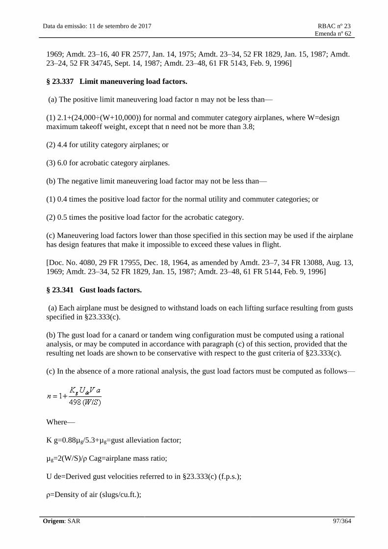
Data da emissão: 11 de setembro de 2017 RBAC nº 23
Emenda nº 62
Origem: SAR 97/364
1969; Amdt. 23–16, 40 FR 2577, Jan. 14, 1975; Amdt. 23–34, 52 FR 1829, Jan. 15, 1987; Amdt.
23–24, 52 FR 34745, Sept. 14, 1987; Amdt. 23–48, 61 FR 5143, Feb. 9, 1996]
§ 23.337 Limit maneuvering load factors.
(a) The positive limit maneuvering load factor n may not be less than—
(1) 2.1+(24,000÷(W+10,000)) for normal and commuter category airplanes, where W=design
maximum takeoff weight, except that n need not be more than 3.8;
(2) 4.4 for utility category airplanes; or
(3) 6.0 for acrobatic category airplanes.
(b) The negative limit maneuvering load factor may not be less than—
(1) 0.4 times the positive load factor for the normal utility and commuter categories; or
(2) 0.5 times the positive load factor for the acrobatic category.
(c) Maneuvering load factors lower than those specified in this section may be used if the airplane
has design features that make it impossible to exceed these values in flight.
[Doc. No. 4080, 29 FR 17955, Dec. 18, 1964, as amended by Amdt. 23–7, 34 FR 13088, Aug. 13,
1969; Amdt. 23–34, 52 FR 1829, Jan. 15, 1987; Amdt. 23–48, 61 FR 5144, Feb. 9, 1996]
§ 23.341 Gust loads factors.
(a) Each airplane must be designed to withstand loads on each lifting surface resulting from gusts
specified in §23.333(c).
(b) The gust load for a canard or tandem wing configuration must be computed using a rational
analysis, or may be computed in accordance with paragraph (c) of this section, provided that the
resulting net loads are shown to be conservative with respect to the gust criteria of §23.333(c).
(c) In the absence of a more rational analysis, the gust load factors must be computed as follows—
Where—
K g=0.88µg/5.3+µg=gust alleviation factor;
µg=2(W/S)/ρ Cag=airplane mass ratio;
U de=Derived gust velocities referred to in §23.333(c) (f.p.s.);
ρ=Density of air (slugs/cu.ft.);

Data da emissão: 11 de setembro de 2017 RBAC nº 23
Emenda nº 62
Origem: SAR 98/364
W/S =Wing loading (p.s.f.) due to the applicable weight of the airplane in the particular load case.
W/S =Wing loading (p.s.f.);
C =Mean geometric chord (ft.);
g =Acceleration due to gravity (ft./sec.2 )
V =Airplane equivalent speed (knots); and
a =Slope of the airplane normal force coefficient curve C NAper radian if the gust loads are applied
to the wings and horizontal tail surfaces simultaneously by a rational method. The wing lift curve
slope C Lper radian may be used when the gust load is applied to the wings only and the horizontal
tail gust loads are treated as a separate condition.
[Amdt. 23–7, 34 FR 13088, Aug. 13, 1969, as amended by Amdt. 23–42, 56 FR 352, Jan. 3, 1991;
Amdt. 23–48, 61 FR 5144, Feb. 9, 1996]
§ 23.343 Design fuel loads.
(a) The disposable load combinations must include each fuel load in the range from zero fuel to the
selected maximum fuel load.
(b) If fuel is carried in the wings, the maximum allowable weight of the airplane without any fuel in
the wing tank(s) must be established as “maximum zero wing fuel weight,” if it is less than the
maximum weight.
(c) For commuter category airplanes, a structural reserve fuel condition, not exceeding fuel
necessary for 45 minutes of operation at maximum continuous power, may be selected. If a
structural reserve fuel condition is selected, it must be used as the minimum fuel weight condition
for showing compliance with the flight load requirements prescribed in this part and—
(1) The structure must be designed to withstand a condition of zero fuel in the wing at limit loads
corresponding to:
(i) Ninety percent of the maneuvering load factors defined in §23.337, and
(ii) Gust velocities equal to 85 percent of the values prescribed in §23.333(c).
(2) The fatigue evaluation of the structure must account for any increase in operating stresses
resulting from the design condition of paragraph (c)(1) of this section.
(3) The flutter, deformation, and vibration requirements must also be met with zero fuel in the
wings.
[Doc. No. 27805, 61 FR 5144, Feb. 9, 1996]
§ 23.345 High lift devices.

Data da emissão: 11 de setembro de 2017 RBAC nº 23
Emenda nº 62
Origem: SAR 99/364
(a) If flaps or similar high lift devices are to be used for takeoff, approach or landing, the airplane,
with the flaps fully extended at VF, is assumed to be subjected to symmetrical maneuvers and gusts
within the range determined by—
(1) Maneuvering, to a positive limit load factor of 2.0; and
(2) Positive and negative gust of 25 feet per second acting normal to the flight path in level flight.
(b) VFmust be assumed to be not less than 1.4 VSor 1.8 VSF, whichever is greater, where—
(1) VSis the computed stalling speed with flaps retracted at the design weight; and
(2) VSFis the computed stalling speed with flaps fully extended at the design weight.
(3) If an automatic flap load limiting device is used, the airplane may be designed for the critical
combinations of airspeed and flap position allowed by that device.
(c) In determining external loads on the airplane as a whole, thrust, slipstream, and pitching
acceleration may be assumed to be zero.
(d) The flaps, their operating mechanism, and their supporting structures, must be designed to
withstand the conditions prescribed in paragraph (a) of this section. In addition, with the flaps fully
extended at VF, the following conditions, taken separately, must be accounted for:
(1) A head-on gust having a velocity of 25 feet per second (EAS), combined with propeller
slipstream corresponding to 75 percent of maximum continuous power; and
(2) The effects of propeller slipstream corresponding to maximum takeoff power.
[Doc. No. 27805, 61 FR 5144, Feb. 9, 1996]
§ 23.347 Unsymmetrical flight conditions.
(a) The airplane is assumed to be subjected to the unsymmetrical flight conditions of §§23.349 and
23.351. Unbalanced aerodynamic moments about the center of gravity must be reacted in a rational
or conservative manner, considering the principal masses furnishing the reacting inertia forces.
(b) Acrobatic category airplanes certified for flick maneuvers (snap roll) must be designed for
additional asymmetric loads acting on the wing and the horizontal tail.
[Doc. No. 4080, 29 FR 17955, Dec. 18, 1964, as amended by Amdt. 23–48, 61 FR 5144, Feb. 9,
1996]
§ 23.349 Rolling conditions.
The wing and wing bracing must be designed for the following loading conditions:
(a) Unsymmetrical wing loads appropriate to the category. Unless the following values result in
Data da emissão: 11 de setembro de 2017 RBAC nº 23
Emenda nº 62
Origem: SAR 100/364
unrealistic loads, the rolling accelerations may be obtained by modifying the symmetrical flight
conditions in §23.333(d) as follows:
(1) For the acrobatic category, in conditions A and F, assume that 100 percent of the semispan wing
airload acts on one side of the plane of symmetry and 60 percent of this load acts on the other side.
(2) For normal, utility, and commuter categories, in Condition A, assume that 100 percent of the
semispan wing airload acts on one side of the airplane and 75 percent of this load acts on the other
side.
(b) The loads resulting from the aileron deflections and speeds specified in §23.455, in combination
with an airplane load factor of at least two thirds of the positive maneuvering load factor used for
design. Unless the following values result in unrealistic loads, the effect of aileron displacement on
wing torsion may be accounted for by adding the following increment to the basic airfoil moment
coefficient over the aileron portion of the span in the critical condition determined in §23.333(d):
Δ c m=−0.01δ
where—
Δ c mis the moment coefficient increment; and
δ is the down aileron deflection in degrees in the critical condition.
[Doc. No. 4080, 29 FR 17955, Dec. 18, 1964, as amended by Amdt. 23–7, 34 FR 13088, Aug. 13,
1969; Amdt. 23–34, 52 FR 1829, Jan. 15, 1987; Amdt. 23–48, 61 FR 5144, Feb. 9, 1996]
§ 23.351 Yawing conditions.
The airplane must be designed for yawing loads on the vertical surfaces resulting from the loads
specified in §§23.441 through 23.445.
[Doc. No. 4080, 29 FR 17955, Dec. 18, 1964; 30 FR 258, Jan. 9, 1965, as amended by Amdt. 23–
42, 56 FR 352, Jan. 3, 1991]
§ 23.361 Engine torque.
(a) Each engine mount and its supporting structure must be designed for the effects of—
(1) A limit engine torque corresponding to takeoff power and propeller speed acting simultaneously
with 75 percent of the limit loads from flight condition A of §23.333(d);
(2) A limit engine torque corresponding to maximum continuous power and propeller speed acting
simultaneously with the limit loads from flight condition A of §23.333(d); and
(3) For turbopropeller installations, in addition to the conditions specified in paragraphs (a)(1) and
(a)(2) of this section, a limit engine torque corresponding to takeoff power and propeller speed,
multiplied by a factor accounting for propeller control system malfunction, including quick
feathering, acting simultaneously with lg level flight loads. In the absence of a rational analysis, a
Data da emissão: 11 de setembro de 2017 RBAC nº 23
Emenda nº 62
Origem: SAR 101/364
factor of 1.6 must be used.
(b) For turbine engine installations, the engine mounts and supporting structure must be designed to
withstand each of the following:
(1) A limit engine torque load imposed by sudden engine stoppage due to malfunction or structural
failure (such as compressor jamming).
(2) A limit engine torque load imposed by the maximum acceleration of the engine.
(c) The limit engine torque to be considered under paragraph (a) of this section must be obtained by
multiplying the mean torque by a factor of—
(1) 1.25 for turbopropeller installations;
(2) 1.33 for engines with five or more cylinders; and
(3) Two, three, or four, for engines with four, three, or two cylinders, respectively.
[Amdt. 23–26, 45 FR 60171, Sept. 11, 1980, as amended by Amdt. 23–45, 58 FR 42160, Aug. 6,
1993]
§ 23.363 Side load on engine mount.
(a) Each engine mount and its supporting structure must be designed for a limit load factor in a
lateral direction, for the side load on the engine mount, of not less than—
(1) 1.33, or
(2) One-third of the limit load factor for flight condition A.
(b) The side load prescribed in paragraph (a) of this section may be assumed to be independent of
other flight conditions.
§ 23.365 Pressurized cabin loads.
For each pressurized compartment, the following apply:
(a) The airplane structure must be strong enough to withstand the flight loads combined with
pressure differential loads from zero up to the maximum relief valve setting.
(b) The external pressure distribution in flight, and any stress concentrations, must be accounted for.
(c) If landings may be made with the cabin pressurized, landing loads must be combined with
pressure differential loads from zero up to the maximum allowed during landing.
(d) The airplane structure must be strong enough to withstand the pressure differential loads
corresponding to the maximum relief valve setting multiplied by a factor of 1.33, omitting other
loads.

Data da emissão: 11 de setembro de 2017 RBAC nº 23
Emenda nº 62
Origem: SAR 102/364
(e) If a pressurized cabin has two or more compartments separated by bulkheads or a floor, the
primary structure must be designed for the effects of sudden release of pressure in any compartment
with external doors or windows. This condition must be investigated for the effects of failure of the
largest opening in the compartment. The effects of intercompartmental venting may be considered.
§ 23.367 Unsymmetrical loads due to engine failure.
(a) Turbopropeller airplanes must be designed for the unsymmetrical loads resulting from the
failure of the critical engine including the following conditions in combination with a single
malfunction of the propeller drag limiting system, considering the probable pilot corrective action
on the flight controls:
(1) At speeds between V MCand V D,the loads resulting from power failure because of fuel flow
interruption are considered to be limit loads.
(2) At speeds between V MCand V C,the loads resulting from the disconnection of the engine
compressor from the turbine or from loss of the turbine blades are considered to be ultimate loads.
(3) The time history of the thrust decay and drag buildup occurring as a result of the prescribed
engine failures must be substantiated by test or other data applicable to the particular engine-
propeller combination.
(4) The timing and magnitude of the probable pilot corrective action must be conservatively
estimated, considering the characteristics of the particular engine-propeller-airplane combination.
(b) Pilot corrective action may be assumed to be initiated at the time maximum yawing velocity is
reached, but not earlier than 2 seconds after the engine failure. The magnitude of the corrective
action may be based on the limit pilot forces specified in §23.397 except that lower forces may be
assumed where it is shown by analysis or test that these forces can control the yaw and roll resulting
from the prescribed engine failure conditions.
[Amdt. 23–7, 34 FR 13089, Aug. 13, 1969]
§ 23.369 Rear lift truss.
(a) If a rear lift truss is used, it must be designed to withstand conditions of reversed airflow at a
design speed of—
V=8.7 √(W/S) + 8.7 (knots), where W/S=wing loading at design maximum takeoff weight.
(b) Either aerodynamic data for the particular wing section used, or a value of C Lequalling −0.8
with a chordwise distribution that is triangular between a peak at the trailing edge and zero at the
leading edge, must be used.
[Doc. No. 4080, 29 FR 17955, Dec. 18, 1964, as amended by Amdt. 23–7, 34 FR 13089, Aug. 13,
1969; 34 FR 17509, Oct. 30, 1969; Amdt. 23–45, 58 FR 42160, Aug. 6, 1993; Amdt. 23–48, 61 FR
5145, Feb. 9, 1996]
§ 23.371 Gyroscopic and aerodynamic loads.

Data da emissão: 11 de setembro de 2017 RBAC nº 23
Emenda nº 62
Origem: SAR 103/364
(a) Each engine mount and its supporting structure must be designed for the gyroscopic, inertial,
and aerodynamic loads that result, with the engine(s) and propeller(s), if applicable, at maximum
continuous r.p.m., under either:
(1) The conditions prescribed in §23.351 and §23.423; or
(2) All possible combinations of the following—
(i) A yaw velocity of 2.5 radians per second;
(ii) A pitch velocity of 1.0 radian per second;
(iii) A normal load factor of 2.5; and
(iv) Maximum continuous thrust.
(b) For airplanes approved for aerobatic maneuvers, each engine mount and its supporting structure
must meet the requirements of paragraph (a) of this section and be designed to withstand the load
factors expected during combined maximum yaw and pitch velocities.
(c) For airplanes certificated in the commuter category, each engine mount and its supporting
structure must meet the requirements of paragraph (a) of this section and the gust conditions
specified in §23.341 of this part.
[Doc. No. 27805, 61 FR 5145, Feb. 9, 1996]
§ 23.373 Speed control devices.
If speed control devices (such as spoilers and drag flaps) are incorporated for use in enroute
conditions—
(a) The airplane must be designed for the symmetrical maneuvers and gusts prescribed in §§23.333,
23.337, and 23.341, and the yawing maneuvers and lateral gusts in §§23.441 and 23.443, with the
device extended at speeds up to the placard device extended speed; and
(b) If the device has automatic operating or load limiting features, the airplane must be designed for
the maneuver and gust conditions prescribed in paragraph (a) of this section at the speeds and
corresponding device positions that the mechanism allows.
[Amdt. 23–7, 34 FR 13089, Aug. 13, 1969]
Control Surface and System Loads
§ 23.391 Control surface loads.
The control surface loads specified in §§23.397 through 23.459 are assumed to occur in the
conditions described in §§23.331 through 23.351.
[Doc. No. 4080, 29 FR 17955, Dec. 18, 1964, as amended by Amdt. 23–48, 61 FR 5145, Feb. 9,

Data da emissão: 11 de setembro de 2017 RBAC nº 23
Emenda nº 62
Origem: SAR 104/364
1996]
§ 23.393 Loads parallel to hinge line.
(a) Control surfaces and supporting hinge brackets must be designed to withstand inertial loads
acting parallel to the hinge line.
(b) In the absence of more rational data, the inertial loads may be assumed to be equal to KW,
where—
(1) K=24 for vertical surfaces;
(2) K=12 for horizontal surfaces; and
(3) W=weight of the movable surfaces.
[Doc. No. 27805, 61 FR 5145, Feb. 9, 1996]
§ 23.395 Control system loads.
(a) Each flight control system and its supporting structure must be designed for loads corresponding
to at least 125 percent of the computed hinge moments of the movable control surface in the
conditions prescribed in §§23.391 through 23.459. In addition, the following apply:
(1) The system limit loads need not exceed the higher of the loads that can be produced by the pilot
and automatic devices operating the controls. However, autopilot forces need not be added to pilot
forces. The system must be designed for the maximum effort of the pilot or autopilot, whichever is
higher. In addition, if the pilot and the autopilot act in opposition, the part of the system between
them may be designed for the maximum effort of the one that imposes the lesser load. Pilot forces
used for design need not exceed the maximum forces prescribed in §23.397(b).
(2) The design must, in any case, provide a rugged system for service use, considering jamming,
ground gusts, taxiing downwind, control inertia, and friction. Compliance with this subparagraph
may be shown by designing for loads resulting from application of the minimum forces prescribed
in §23.397(b).
(b) A 125 percent factor on computed hinge moments must be used to design elevator, aileron, and
rudder systems. However, a factor as low as 1.0 may be used if hinge moments are based on
accurate flight test data, the exact reduction depending upon the accuracy and reliability of the data.
(c) Pilot forces used for design are assumed to act at the appropriate control grips or pads as they
would in flight, and to react at the attachments of the control system to the control surface horns.
[Doc. No. 4080, 29 FR 17955, Dec. 18, 1964, as amended by Amdt. 23–7, 34 FR 13089, Aug. 13,
1969]
§ 23.397 Limit control forces and torques.
(a) In the control surface flight loading condition, the airloads on movable surfaces and the
corresponding deflections need not exceed those that would result in flight from the application of
any pilot force within the ranges specified in paragraph (b) of this section. In applying this criterion,

Data da emissão: 11 de setembro de 2017 RBAC nº 23
Emenda nº 62
Origem: SAR 105/364
the effects of control system boost and servo-mechanisms, and the effects of tabs must be
considered. The automatic pilot effort must be used for design if it alone can produce higher control
surface loads than the human pilot.
(b) The limit pilot forces and torques are as follows:
Control
Maximum forces or torques for design weight,
weight equal to or less than 5,000
pounds1
Minimum forces
or
torques2
Aileron:
Stick 67 lbs 40 lbs.
Wheel3 50 D in.-lbs4 40 D in.-lbs.4
Elevator:
Stick 167 lbs 100 lbs.
Wheel
(symmetrical)
200 lbs 100 lbs.
Wheel
(unsymmetrical)5
100 lbs.
Rudder 200 lbs 150 lbs. 1For design weight ( W ) more than 5,000 pounds, the specified maximum values must be increased
linearly with weight to 1.18 times the specified values at a design weight of 12,500 pounds and for
commuter category airplanes, the specified values must be increased linearly with weight to 1.35
times the specified values at a design weight of 19,000 pounds.
2If the design of any individual set of control systems or surfaces makes these specified minimum
forces or torques inapplicable, values corresponding to the present hinge moments obtained under
§23.415, but not less than 0.6 of the specified minimum forces or torques, may be used.
3The critical parts of the aileron control system must also be designed for a single tangential force
with a limit value of 1.25 times the couple force determined from the above criteria.
4D=wheel diameter (inches).
5The unsymmetrical force must be applied at one of the normal handgrip points on the control
wheel.
[Doc. No. 4080, 29 FR 17955, Dec. 18, 1964, as amended by Amdt. 23–7, 34 FR 13089, Aug. 13,
1969; Amdt. 23–17, 41 FR 55464, Dec. 20, 1976; Amdt. 23–34, 52 FR 1829, Jan. 15, 1987; Amdt.
23–45, 58 FR 42160, Aug. 6, 1993]
§ 23.399 Dual control system.
(a) Each dual control system must be designed to withstand the force of the pilots operating in
opposition, using individual pilot forces not less than the greater of—

Data da emissão: 11 de setembro de 2017 RBAC nº 23
Emenda nº 62
Origem: SAR 106/364
(1) 0.75 times those obtained under §23.395; or
(2) The minimum forces specified in §23.397(b).
(b) Each dual control system must be designed to withstand the force of the pilots applied together,
in the same direction, using individual pilot forces not less than 0.75 times those obtained under
§23.395.
[Doc. No. 27805, 61 FR 5145, Feb. 9, 1996]
§ 23.405 Secondary control system.
Secondary controls, such as wheel brakes, spoilers, and tab controls, must be designed for the
maximum forces that a pilot is likely to apply to those controls.
§ 23.407 Trim tab effects.
The effects of trim tabs on the control surface design conditions must be accounted for only where
the surface loads are limited by maximum pilot effort. In these cases, the tabs are considered to be
deflected in the direction that would assist the pilot. These deflections must correspond to the
maximum degree of “out of trim” expected at the speed for the condition under consideration.
§ 23.409 Tabs.
Control surface tabs must be designed for the most severe combination of airspeed and tab
deflection likely to be obtained within the flight envelope for any usable loading condition.
§ 23.415 Ground gust conditions.
(a) The control system must be investigated as follows for control surface loads due to ground
gusts and taxiing downwind:
(1) If an investigation of the control system for ground gust loads is not required by paragraph
(a)(2) of this section, but the applicant elects to design a part of the control system of these loads,
these loads need only be carried from control surface horns through the nearest stops or gust locks
and their supporting structures.
(2) If pilot forces less than the minimums specified in §23.397(b) are used for design, the effects of
surface loads due to ground gusts and taxiing downwind must be investigated for the entire control
system according to the formula:
H=K c S q
where—
H=limit hinge moment (ft.-lbs.);
c=mean chord of the control surface aft of the hinge line (ft.);
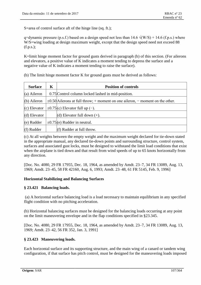
Data da emissão: 11 de setembro de 2017 RBAC nº 23
Emenda nº 62
Origem: SAR 107/364
S=area of control surface aft of the hinge line (sq. ft.);
q=dynamic pressure (p.s.f.) based on a design speed not less than 14.6 √(W/S) + 14.6 (f.p.s.) where
W/S=wing loading at design maximum weight, except that the design speed need not exceed 88
(f.p.s.);
K=limit hinge moment factor for ground gusts derived in paragraph (b) of this section. (For ailerons
and elevators, a positive value of K indicates a moment tending to depress the surface and a
negative value of K indicates a moment tending to raise the surface).
(b) The limit hinge moment factor K for ground gusts must be derived as follows:
Surface K Position of controls
(a) Aileron 0.75 Control column locked lashed in mid-position.
(b) Aileron ±0.50 Ailerons at full throw; + moment on one aileron, − moment on the other.
(c) Elevator ±0.75 (c) Elevator full up (−).
(d) Elevator (d) Elevator full down (+).
(e) Rudder ±0.75 (e) Rudder in neutral.
(f) Rudder (f) Rudder at full throw.
(c) At all weights between the empty weight and the maximum weight declared for tie-down stated
in the appropriate manual, any declared tie-down points and surrounding structure, control system,
surfaces and associated gust locks, must be designed to withstand the limit load conditions that exist
when the airplane is tied down and that result from wind speeds of up to 65 knots horizontally from
any direction.
[Doc. No. 4080, 29 FR 17955, Dec. 18, 1964, as amended by Amdt. 23–7, 34 FR 13089, Aug. 13,
1969; Amdt. 23–45, 58 FR 42160, Aug. 6, 1993; Amdt. 23–48, 61 FR 5145, Feb. 9, 1996]
Horizontal Stabilizing and Balancing Surfaces
§ 23.421 Balancing loads.
(a) A horizontal surface balancing load is a load necessary to maintain equilibrium in any specified
flight condition with no pitching acceleration.
(b) Horizontal balancing surfaces must be designed for the balancing loads occurring at any point
on the limit maneuvering envelope and in the flap conditions specified in §23.345.
[Doc. No. 4080, 29 FR 17955, Dec. 18, 1964, as amended by Amdt. 23–7, 34 FR 13089, Aug. 13,
1969; Amdt. 23–42, 56 FR 352, Jan. 3, 1991]
§ 23.423 Maneuvering loads.
Each horizontal surface and its supporting structure, and the main wing of a canard or tandem wing
configuration, if that surface has pitch control, must be designed for the maneuvering loads imposed
Data da emissão: 11 de setembro de 2017 RBAC nº 23
Emenda nº 62
Origem: SAR 108/364
by the following conditions:
(a) A sudden movement of the pitching control, at the speed VA, to the maximum aft movement,
and the maximum forward movement, as limited by the control stops, or pilot effort, whichever is
critical.
(b) A sudden aft movement of the pitching control at speeds above VA, followed by a forward
movement of the pitching control resulting in the following combinations of normal and angular
acceleration:
Condition Normal acceleration (n) Angular acceleration (radian/sec2)
Nose-up pitching 1.0 +39nm÷V×(nm−1.5)
Nose-down pitching nm −39nm÷V×(nm−1.5)
where—
(1) nm=positive limit maneuvering load factor used in the design of the airplane; and
(2) V=initial speed in knots.
The conditions in this paragraph involve loads corresponding to the loads that may occur in a
“checked maneuver” (a maneuver in which the pitching control is suddenly displaced in one
direction and then suddenly moved in the opposite direction). The deflections and timing of the
“checked maneuver” must avoid exceeding the limit maneuvering load factor. The total horizontal
surface load for both nose-up and nose-down pitching conditions is the sum of the balancing loads
at V and the specified value of the normal load factor n, plus the maneuvering load increment due to
the specified value of the angular acceleration.
[Amdt. 23–42, 56 FR 353, Jan. 3, 1991; 56 FR 5455, Feb. 11, 1991]
§ 23.425 Gust loads.
(a) Each horizontal surface, other than a main wing, must be designed for loads resulting from—
(1) Gust velocities specified in §23.333(c) with flaps retracted; and
(2) Positive and negative gusts of 25 f.p.s. nominal intensity at V Fcorresponding to the flight
conditions specified in §23.345(a)(2).
(b) [Reserved]
(c) When determining the total load on the horizontal surfaces for the conditions specified in
paragraph (a) of this section, the initial balancing loads for steady unaccelerated flight at the
pertinent design speeds VF, VC, and VDmust first be determined. The incremental load resulting
from the gusts must be added to the initial balancing load to obtain the total load.
(d) In the absence of a more rational analysis, the incremental load due to the gust must be

Data da emissão: 11 de setembro de 2017 RBAC nº 23
Emenda nº 62
Origem: SAR 109/364
computed as follows only on airplane configurations with aft-mounted, horizontal surfaces, unless
its use elsewhere is shown to be conservative:
where—
ΔLht=Incremental horizontal tailload (lbs.);
Kg=Gust alleviation factor defined in §23.341;
Ude=Derived gust velocity (f.p.s.);
V=Airplane equivalent speed (knots);
aht=Slope of aft horizontal lift curve (per radian)
Sht=Area of aft horizontal lift surface (ft2 ); and
[Doc. No. 4080, 29 FR 17955, Dec. 18, 1964, as amended by Amdt. 23–7, 34 FR 13089 Aug. 13,
1969; Amdt. 23–42, 56 FR 353, Jan. 3, 1991]
§ 23.427 Unsymmetrical loads.
(a) Horizontal surfaces other than main wing and their supporting structure must be designed for
unsymmetrical loads arising from yawing and slipstream effects, in combination with the loads
prescribed for the flight conditions set forth in §§23.421 through 23.425.
(b) In the absence of more rational data for airplanes that are conventional in regard to location of
engines, wings, horizontal surfaces other than main wing, and fuselage shape:
(1) 100 percent of the maximum loading from the symmetrical flight conditions may be assumed on
the surface on one side of the plane of symmetry; and
(2) The following percentage of that loading must be applied to the opposite side:
Percent=100−10 (n−1), where n is the specified positive maneuvering load factor, but this value
may not be more than 80 percent.
(c) For airplanes that are not conventional (such as airplanes with horizontal surfaces other than
main wing having appreciable dihedral or supported by the vertical tail surfaces) the surfaces and
supporting structures must be designed for combined vertical and horizontal surface loads resulting
from each prescribed flight condition taken separately.

Data da emissão: 11 de setembro de 2017 RBAC nº 23
Emenda nº 62
Origem: SAR 110/364
[Amdt. 23–14, 38 FR 31820, Nov. 19, 1973, as amended by Amdt. 23–42, 56 FR 353, Jan. 3, 1991]
Vertical Surfaces
§ 23.441 Maneuvering loads.
(a) At speeds up to V A,the vertical surfaces must be designed to withstand the following
conditions. In computing the loads, the yawing velocity may be assumed to be zero:
(1) With the airplane in unaccelerated flight at zero yaw, it is assumed that the rudder control is
suddenly displaced to the maximum deflection, as limited by the control stops or by limit pilot
forces.
(2) With the rudder deflected as specified in paragraph (a)(1) of this section, it is assumed that the
airplane yaws to the overswing sideslip angle. In lieu of a rational analysis, an overswing angle
equal to 1.5 times the static sideslip angle of paragraph (a)(3) of this section may be assumed.
(3) A yaw angle of 15 degrees with the rudder control maintained in the neutral position (except as
limited by pilot strength).
(b) For commuter category airplanes, the loads imposed by the following additional maneuver must
be substantiated at speeds from VAto VD/MD. When computing the tail loads—
(1) The airplane must be yawed to the largest attainable steady state sideslip angle, with the rudder
at maximum deflection caused by any one of the following:
(i) Control surface stops;
(ii) Maximum available booster effort;
(iii) Maximum pilot rudder force as shown below:

Data da emissão: 11 de setembro de 2017 RBAC nº 23
Emenda nº 62
Origem: SAR 111/364
(2) The rudder must be suddenly displaced from the maximum deflection to the neutral position.
(c) The yaw angles specified in paragraph (a)(3) of this section may be reduced if the yaw angle
chosen for a particular speed cannot be exceeded in—
(1) Steady slip conditions;
(2) Uncoordinated rolls from steep banks; or
(3) Sudden failure of the critical engine with delayed corrective action.
[Doc. No. 4080, 29 FR 17955, Dec. 18, 1964, as amended by Amdt. 23–7, 34 FR 13090, Aug. 13,
1969; Amdt. 23–14, 38 FR 31821, Nov. 19, 1973; Amdt. 23–28, 47 FR 13315, Mar. 29, 1982;
Amdt. 23–42, 56 FR 353, Jan. 3, 1991; Amdt. 23–48, 61 FR 5145, Feb. 9, 1996]

Data da emissão: 11 de setembro de 2017 RBAC nº 23
Emenda nº 62
Origem: SAR 112/364
§ 23.443 Gust loads.
(a) Vertical surfaces must be designed to withstand, in unaccelerated flight at speed V C,lateral
gusts of the values prescribed for V Cin §23.333(c).
(b) In addition, for commuter category airplanes, the airplane is assumed to encounter derived gusts
normal to the plane of symmetry while in unaccelerated flight at VB, VC, VD, and VF. The derived
gusts and airplane speeds corresponding to these conditions, as determined by §§23.341 and 23.345,
must be investigated. The shape of the gust must be as specified in §23.333(c)(2)(i).
(c) In the absence of a more rational analysis, the gust load must be computed as follows:
Where—
Lvt=Vertical surface loads (lbs.);
Ude=Derived gust velocity (f.p.s.);
ρ=Air density (slugs/cu.ft.);
W=the applicable weight of the airplane in the particular load case (lbs.);
Svt=Area of vertical surface (ft.2 );
ct=Mean geometric chord of vertical surface (ft.);
avt=Lift curve slope of vertical surface (per radian);
K=Radius of gyration in yaw (ft.);
lvt=Distance from airplane c.g. to lift center of vertical surface (ft.);
g=Acceleration due to gravity (ft./sec.2 ); and
V=Equivalent airspeed (knots).
[Amdt. 23–7, 34 FR 13090, Aug. 13, 1969, as amended by Amdt. 23–34, 52 FR 1830, Jan. 15,
1987; 52 FR 7262, Mar. 9, 1987; Amdt. 23–24, 52 FR 34745, Sept. 14, 1987; Amdt. 23–42, 56 FR
353, Jan. 3, 1991; Amdt. 23–48, 61 FR 5147, Feb. 9, 1996]

Data da emissão: 11 de setembro de 2017 RBAC nº 23
Emenda nº 62
Origem: SAR 113/364
§ 23.445 Outboard fins or winglets.
(a) If outboard fins or winglets are included on the horizontal surfaces or wings, the horizontal
surfaces or wings must be designed for their maximum load in combination with loads induced by
the fins or winglets and moments or forces exerted on the horizontal surfaces or wings by the fins or
winglets.
(b) If outboard fins or winglets extend above and below the horizontal surface, the critical vertical
surface loading (the load per unit area as determined under §§23.441 and 23.443) must be applied
to—
(1) The part of the vertical surfaces above the horizontal surface with 80 percent of that loading
applied to the part below the horizontal surface; and
(2) The part of the vertical surfaces below the horizontal surface with 80 percent of that loading
applied to the part above the horizontal surface.
(c) The end plate effects of outboard fins or winglets must be taken into account in applying the
yawing conditions of §§23.441 and 23.443 to the vertical surfaces in paragraph (b) of this section.
(d) When rational methods are used for computing loads, the maneuvering loads of §23.441 on the
vertical surfaces and the one-g horizontal surface load, including induced loads on the horizontal
surface and moments or forces exerted on the horizontal surfaces by the vertical surfaces, must be
applied simultaneously for the structural loading condition.
[Doc. No. 4080, 29 FR 17955, Dec. 18, 1964, as amended by Amdt. 23–14, 38 FR 31821, Nov. 19,
1973; Amdt. 23–42, 56 FR 353, Jan. 3, 1991]
Ailerons and Special Devices
§ 23.455 Ailerons.
(a) The ailerons must be designed for the loads to which they are subjected—
(1) In the neutral position during symmetrical flight conditions; and
(2) By the following deflections (except as limited by pilot effort), during unsymmetrical flight
conditions:
(i) Sudden maximum displacement of the aileron control at V A.Suitable allowance may be made
for control system deflections.
(ii) Sufficient deflection at V C,where V Cis more than V A,to produce a rate of roll not less than
obtained in paragraph (a)(2)(i) of this section.
(iii) Sufficient deflection at V Dto produce a rate of roll not less than one-third of that obtained in
paragraph (a)(2)(i) of this section.
(b) [Reserved]

Data da emissão: 11 de setembro de 2017 RBAC nº 23
Emenda nº 62
Origem: SAR 114/364
[Doc. No. 4080, 29 FR 17955, Dec. 18, 1964, as amended by Amdt. 23–7, 34 FR 13090, Aug. 13,
1969; Amdt. 23–42, 56 FR 353, Jan. 3, 1991]
§ 23.459 Special devices.
The loading for special devices using aerodynamic surfaces (such as slots and spoilers) must be
determined from test data.
Ground Loads
§ 23.471 General.
The limit ground loads specified in this subpart are considered to be external loads and inertia
forces that act upon an airplane structure. In each specified ground load condition, the external
reactions must be placed in equilibrium with the linear and angular inertia forces in a rational or
conservative manner.
§ 23.473 Ground load conditions and assumptions.
(a) The ground load requirements of this subpart must be complied with at the design maximum
weight except that §§23.479, 23.481, and 23.483 may be complied with at a design landing weight
(the highest weight for landing conditions at the maximum descent velocity) allowed under
paragraphs (b) and (c) of this section.
(b) The design landing weight may be as low as—
(1) 95 percent of the maximum weight if the minimum fuel capacity is enough for at least one-half
hour of operation at maximum continuous power plus a capacity equal to a fuel weight which is the
difference between the design maximum weight and the design landing weight; or
(2) The design maximum weight less the weight of 25 percent of the total fuel capacity.
(c) The design landing weight of a multiengine airplane may be less than that allowed under
paragraph (b) of this section if—
(1) The airplane meets the one-engine-inoperative climb requirements of §23.67(b)(1) or (c); and
(2) Compliance is shown with the fuel jettisoning system requirements of §23.1001.
(d) The selected limit vertical inertia load factor at the center of gravity of the airplane for the
ground load conditions prescribed in this subpart may not be less than that which would be obtained
when landing with a descent velocity ( V ), in feet per second, equal to 4.4 (W/S)1/4, except that
this velocity need not be more than 10 feet per second and may not be less than seven feet per
second.
(e) Wing lift not exceeding two-thirds of the weight of the airplane may be assumed to exist
throughout the landing impact and to act through the center of gravity. The ground reaction load
factor may be equal to the inertia load factor minus the ratio of the above assumed wing lift to the
airplane weight.

Data da emissão: 11 de setembro de 2017 RBAC nº 23
Emenda nº 62
Origem: SAR 115/364
(f) If energy absorption tests are made to determine the limit load factor corresponding to the
required limit descent velocities, these tests must be made under §23.723(a).
(g) No inertia load factor used for design purposes may be less than 2.67, nor may the limit ground
reaction load factor be less than 2.0 at design maximum weight, unless these lower values will not
be exceeded in taxiing at speeds up to takeoff speed over terrain as rough as that expected in
service.
[Doc. No. 4080, 29 FR 17955, Dec. 18, 1964, as amended by Amdt. 23–7, 34 FR 13090, Aug. 13,
1969; Amdt. 23–28, 47 FR 13315, Mar. 29, 1982; Amdt. 23–45, 58 FR 42160, Aug. 6, 1993; Amdt.
23–48, 61 FR 5147, Feb. 9, 1996]
§ 23.477 Landing gear arrangement.
Sections 23.479 through 23.483, or the conditions in appendix C, apply to airplanes with
conventional arrangements of main and nose gear, or main and tail gear.
§ 23.479 Level landing conditions.
(a) For a level landing, the airplane is assumed to be in the following attitudes:
(1) For airplanes with tail wheels, a normal level flight attitude.
(2) For airplanes with nose wheels, attitudes in which—
(i) The nose and main wheels contact the ground simultaneously; and
(ii) The main wheels contact the ground and the nose wheel is just clear of the ground.
The attitude used in paragraph (a)(2)(i) of this section may be used in the analysis required under
paragraph (a)(2)(ii) of this section.
(b) When investigating landing conditions, the drag components simulating the forces required to
accelerate the tires and wheels up to the landing speed (spin-up) must be properly combined with
the corresponding instantaneous vertical ground reactions, and the forward-acting horizontal loads
resulting from rapid reduction of the spin-up drag loads (spring-back) must be combined with
vertical ground reactions at the instant of the peak forward load, assuming wing lift and a tire-
sliding coefficient of friction of 0.8. However, the drag loads may not be less than 25 percent of the
maximum vertical ground reactions (neglecting wing lift).
(c) In the absence of specific tests or a more rational analysis for determining the wheel spin-up and
spring-back loads for landing conditions, the method set forth in appendix D of this part must be
used. If appendix D of this part is used, the drag components used for design must not be less than
those given by appendix C of this part.
(d) For airplanes with tip tanks or large overhung masses (such as turbo-propeller or jet engines)
supported by the wing, the tip tanks and the structure supporting the tanks or overhung masses must
be designed for the effects of dynamic responses under the level landing conditions of either
paragraph (a)(1) or (a)(2)(ii) of this section. In evaluating the effects of dynamic response, an
Data da emissão: 11 de setembro de 2017 RBAC nº 23
Emenda nº 62
Origem: SAR 116/364
airplane lift equal to the weight of the airplane may be assumed.
[Doc. No. 4080, 29 FR 17955, Dec. 18, 1964, as amended by Amdt. 23–17, 41 FR 55464, Dec. 20,
1976; Amdt. 23–45, 58 FR 42160, Aug. 6, 1993]
§ 23.481 Tail down landing conditions.
(a) For a tail down landing, the airplane is assumed to be in the following attitudes:
(1) For airplanes with tail wheels, an attitude in which the main and tail wheels contact the ground
simultaneously.
(2) For airplanes with nose wheels, a stalling attitude, or the maximum angle allowing ground
clearance by each part of the airplane, whichever is less.
(b) For airplanes with either tail or nose wheels, ground reactions are assumed to be vertical, with
the wheels up to speed before the maximum vertical load is attained.
§ 23.483 One-wheel landing conditions.
For the one-wheel landing condition, the airplane is assumed to be in the level attitude and to
contact the ground on one side of the main landing gear. In this attitude, the ground reactions must
be the same as those obtained on that side under §23.479.
§ 23.485 Side load conditions.
(a) For the side load condition, the airplane is assumed to be in a level attitude with only the main
wheels contacting the ground and with the shock absorbers and tires in their static positions.
(b) The limit vertical load factor must be 1.33, with the vertical ground reaction divided equally
between the main wheels.
(c) The limit side inertia factor must be 0.83, with the side ground reaction divided between the
main wheels so that—
(1) 0.5 ( W ) is acting inboard on one side; and
(2) 0.33 ( W ) is acting outboard on the other side.
(d) The side loads prescribed in paragraph (c) of this section are assumed to be applied at the
ground contact point and the drag loads may be assumed to be zero.
[Doc. No. 4080, 29 FR 17955, Dec. 18, 1964, as amended by Amdt. 23–45, 58 FR 42160, Aug. 6,
1993]
§ 23.493 Braked roll conditions.
Under braked roll conditions, with the shock absorbers and tires in their static positions, the
following apply:

Data da emissão: 11 de setembro de 2017 RBAC nº 23
Emenda nº 62
Origem: SAR 117/364
(a) The limit vertical load factor must be 1.33.
(b) The attitudes and ground contacts must be those described in §23.479 for level landings.
(c) A drag reaction equal to the vertical reaction at the wheel multiplied by a coefficient of friction
of 0.8 must be applied at the ground contact point of each wheel with brakes, except that the drag
reaction need not exceed the maximum value based on limiting brake torque.
§ 23.497 Supplementary conditions for tail wheels.
In determining the ground loads on the tail wheel and affected supporting structures, the following
apply:
(a) For the obstruction load, the limit ground reaction obtained in the tail down landing condition is
assumed to act up and aft through the axle at 45 degrees. The shock absorber and tire may be
assumed to be in their static positions.
(b) For the side load, a limit vertical ground reaction equal to the static load on the tail wheel, in
combination with a side component of equal magnitude, is assumed. In addition—
(1) If a swivel is used, the tail wheel is assumed to be swiveled 90 degrees to the airplane
longitudinal axis with the resultant ground load passing through the axle;
(2) If a lock, steering device, or shimmy damper is used, the tail wheel is also assumed to be in the
trailing position with the side load acting at the ground contact point; and
(3) The shock absorber and tire are assumed to be in their static positions.
(c) If a tail wheel, bumper, or an energy absorption device is provided to show compliance with
§23.925(b), the following apply:
(1) Suitable design loads must be established for the tail wheel, bumper, or energy absorption
device; and
(2) The supporting structure of the tail wheel, bumper, or energy absorption device must be
designed to withstand the loads established in paragraph (c)(1) of this section.
[Doc. No. 4080, 29 FR 17955, Dec. 18, 1964, as amended by Amdt. 23–48, 61 FR 5147, Feb. 9,
1996]
§ 23.499 Supplementary conditions for nose wheels.
In determining the ground loads on nose wheels and affected supporting structures, and assuming
that the shock absorbers and tires are in their static positions, the following conditions must be met:
(a) For aft loads, the limit force components at the axle must be—
(1) A vertical component of 2.25 times the static load on the wheel; and

Data da emissão: 11 de setembro de 2017 RBAC nº 23
Emenda nº 62
Origem: SAR 118/364
(2) A drag component of 0.8 times the vertical load.
(b) For forward loads, the limit force components at the axle must be—
(1) A vertical component of 2.25 times the static load on the wheel; and
(2) A forward component of 0.4 times the vertical load.
(c) For side loads, the limit force components at ground contact must be—
(1) A vertical component of 2.25 times the static load on the wheel; and
(2) A side component of 0.7 times the vertical load.
(d) For airplanes with a steerable nose wheel that is controlled by hydraulic or other power, at
design takeoff weight with the nose wheel in any steerable position, the application of 1.33 times
the full steering torque combined with a vertical reaction equal to 1.33 times the maximum static
reaction on the nose gear must be assumed. However, if a torque limiting device is installed, the
steering torque can be reduced to the maximum value allowed by that device.
(e) For airplanes with a steerable nose wheel that has a direct mechanical connection to the rudder
pedals, the mechanism must be designed to withstand the steering torque for the maximum pilot
forces specified in §23.397(b).
[Doc. No. 4080, 29 FR 17955, Dec. 18, 1964, as amended by Amdt. 23–48, 61 FR 5147, Feb. 9,
1996]
§ 23.505 Supplementary conditions for skiplanes.
In determining ground loads for skiplanes, and assuming that the airplane is resting on the ground
with one main ski frozen at rest and the other skis free to slide, a limit side force equal to 0.036
times the design maximum weight must be applied near the tail assembly, with a factor of safety of
1.
[Amdt. 23–7, 34 FR 13090, Aug. 13, 1969]
§ 23.507 Jacking loads.
(a) The airplane must be designed for the loads developed when the aircraft is supported on jacks at
the design maximum weight assuming the following load factors for landing gear jacking points at a
three-point attitude and for primary flight structure jacking points in the level attitude:
(1) Vertical-load factor of 1.35 times the static reactions.
(2) Fore, aft, and lateral load factors of 0.4 times the vertical static reactions.
(b) The horizontal loads at the jack points must be reacted by inertia forces so as to result in no
change in the direction of the resultant loads at the jack points.

Data da emissão: 11 de setembro de 2017 RBAC nº 23
Emenda nº 62
Origem: SAR 119/364
(c) The horizontal loads must be considered in all combinations with the vertical load.
[Amdt. 23–14, 38 FR 31821, Nov. 19, 1973]
§ 23.509 Towing loads.
The towing loads of this section must be applied to the design of tow fittings and their immediate
attaching structure.
(a) The towing loads specified in paragraph (d) of this section must be considered separately. These
loads must be applied at the towing fittings and must act parallel to the ground. In addition:
(1) A vertical load factor equal to 1.0 must be considered acting at the center of gravity; and
(2) The shock struts and tires must be in there static positions.
(b) For towing points not on the landing gear but near the plane of symmetry of the airplane, the
drag and side tow load components specified for the auxiliary gear apply. For towing points located
outboard of the main gear, the drag and side tow load components specified for the main gear apply.
Where the specified angle of swivel cannot be reached, the maximum obtainable angle must be
used.
(c) The towing loads specified in paragraph (d) of this section must be reacted as follows:
(1) The side component of the towing load at the main gear must be reacted by a side force at the
static ground line of the wheel to which the load is applied.
(2) The towing loads at the auxiliary gear and the drag components of the towing loads at the main
gear must be reacted as follows:
(i) A reaction with a maximum value equal to the vertical reaction must be applied at the axle of the
wheel to which the load is applied. Enough airplane inertia to achieve equilibrium must be applied.
(ii) The loads must be reacted by airplane inertia.
(d) The prescribed towing loads are as follows, where W is the design maximum weight:
Tow point Position
Load
Magnitude No. Direction
Main gear 0.225W 1
2
3
4
Forward, parallel to drag axis.
Forward, at 30° to drag axis.
Aft, parallel to drag axis.
Aft, at 30° to drag axis.
Auxiliary gear Swiveled forward 0.3W 5 Forward.

Data da emissão: 11 de setembro de 2017 RBAC nº 23
Emenda nº 62
Origem: SAR 120/364
6 Aft.
Swiveled aft 0.3W 7
8
Forward.
Aft.
Swiveled 45° from forward 0.15W 9
1
0
Forward, in plane of wheel.
Aft, in plane of wheel.
Swiveled 45° from aft 0.15W 11
1
2
Forward, in plane of wheel.
Aft, in plane of wheel.
[Amdt. 23–14, 38 FR 31821, Nov. 19, 1973]
§ 23.511 Ground load; unsymmetrical loads on multiple-wheel units.
(a) Pivoting loads. The airplane is assumed to pivot about on side of the main gear with—
(1) The brakes on the pivoting unit locked; and
(2) Loads corresponding to a limit vertical load factor of 1, and coefficient of friction of 0.8 applied
to the main gear and its supporting structure.
(b) Unequal tire loads. The loads established under §§23.471 through 23.483 must be applied in
turn, in a 60/40 percent distribution, to the dual wheels and tires in each dual wheel landing gear
unit.
(c) Deflated tire loads. For the deflated tire condition—
(1) 60 percent of the loads established under §§23.471 through 23.483 must be applied in turn to
each wheel in a landing gear unit; and
(2) 60 percent of the limit drag and side loads, and 100 percent of the limit vertical load established
under §§23.485 and 23.493 or lesser vertical load obtained under paragraph (c)(1) of this section,
must be applied in turn to each wheel in the dual wheel landing gear unit.
[Amdt. 23–7, 34 FR 13090, Aug. 13, 1969]
Water Loads
§ 23.521 Water load conditions.
(a) The structure of seaplanes and amphibians must be designed for water loads developed during
takeoff and landing with the seaplane in any attitude likely to occur in normal operation at
appropriate forward and sinking velocities under the most severe sea conditions likely to be
encountered.
(b) Unless the applicant makes a rational analysis of the water loads, §§23.523 through 23.537
apply.
Data da emissão: 11 de setembro de 2017 RBAC nº 23
Emenda nº 62
Origem: SAR 121/364
[Doc. No. 4080, 29 FR 17955, Dec. 18, 1964, as amended by Amdt. 23–45, 58 FR 42160, Aug. 6,
1993; Amdt. 23–48, 61 FR 5147, Feb. 9, 1996]
§ 23.523 Design weights and center of gravity positions.
(a) Design weights. The water load requirements must be met at each operating weight up to the
design landing weight except that, for the takeoff condition prescribed in §23.531, the design water
takeoff weight (the maximum weight for water taxi and takeoff run) must be used.
(b) Center of gravity positions. The critical centers of gravity within the limits for which
certification is requested must be considered to reach maximum design loads for each part of the
seaplane structure.
[Doc. No. 26269, 58 FR 42160, Aug. 6, 1993]
§ 23.525 Application of loads.
(a) Unless otherwise prescribed, the seaplane as a whole is assumed to be subjected to the loads
corresponding to the load factors specified in §23.527.
(b) In applying the loads resulting from the load factors prescribed in §23.527, the loads may be
distributed over the hull or main float bottom (in order to avoid excessive local shear loads and
bending moments at the location of water load application) using pressures not less than those
prescribed in §23.533(c).
(c) For twin float seaplanes, each float must be treated as an equivalent hull on a fictitious seaplane
with a weight equal to one-half the weight of the twin float seaplane.
(d) Except in the takeoff condition of §23.531, the aerodynamic lift on the seaplane during the
impact is assumed to be2/3of the weight of the seaplane.
[Doc. No. 26269, 58 FR 42161, Aug. 6, 1993; 58 FR 51970, Oct. 5, 1993]
§ 23.527 Hull and main float load factors.
(a) Water reaction load factors nwmust be computed in the following manner:
(1) For the step landing case
(2) For the bow and stern landing cases
Data da emissão: 11 de setembro de 2017 RBAC nº 23
Emenda nº 62
Origem: SAR 122/364
(b) The following values are used:
(1) nw=water reaction load factor (that is, the water reaction divided by seaplane weight).
(2) C1=empirical seaplane operations factor equal to 0.012 (except that this factor may not be less
than that necessary to obtain the minimum value of step load factor of 2.33).
(3) VSO=seaplane stalling speed in knots with flaps extended in the appropriate landing position and
with no slipstream effect.
(4) β=Angle of dead rise at the longitudinal station at which the load factor is being determined in
accordance with figure 1 of appendix I of this part.
(5) W=seaplane landing weight in pounds.
(6) K1=empirical hull station weighing factor, in accordance with figure 2 of appendix I of this part.
(7) rx=ratio of distance, measured parallel to hull reference axis, from the center of gravity of the
seaplane to the hull longitudinal station at which the load factor is being computed to the radius of
gyration in pitch of the seaplane, the hull reference axis being a straight line, in the plane of
symmetry, tangential to the keel at the main step.
(c) For a twin float seaplane, because of the effect of flexibility of the attachment of the floats to the
seaplane, the factor K1may be reduced at the bow and stern to 0.8 of the value shown in figure 2 of
appendix I of this part. This reduction applies only to the design of the carrythrough and seaplane
structure.
[Doc. No. 26269, 58 FR 42161, Aug. 6, 1993; 58 FR 51970, Oct. 5, 1993]
§ 23.529 Hull and main float landing conditions.
(a) Symmetrical step, bow, and stern landing. For symmetrical step, bow, and stern landings, the
limit water reaction load factors are those computed under §23.527. In addition—
(1) For symmetrical step landings, the resultant water load must be applied at the keel, through the
center of gravity, and must be directed perpendicularly to the keel line;
(2) For symmetrical bow landings, the resultant water load must be applied at the keel, one-fifth of
the longitudinal distance from the bow to the step, and must be directed perpendicularly to the keel
line; and
(3) For symmetrical stern landings, the resultant water load must be applied at the keel, at a point 85
percent of the longitudinal distance from the step to the stern post, and must be directed
perpendicularly to the keel line.
(b) Unsymmetrical landing for hull and single float seaplanes. Unsymmetrical step, bow, and stern
landing conditions must be investigated. In addition—
(1) The loading for each condition consists of an upward component and a side component equal,

Data da emissão: 11 de setembro de 2017 RBAC nº 23
Emenda nº 62
Origem: SAR 123/364
respectively, to 0.75 and 0.25 tan β times the resultant load in the corresponding symmetrical
landing condition; and
(2) The point of application and direction of the upward component of the load is the same as that in
the symmetrical condition, and the point of application of the side component is at the same
longitudinal station as the upward component but is directed inward perpendicularly to the plane of
symmetry at a point midway between the keel and chine lines.
(c) Unsymmetrical landing; twin float seaplanes. The unsymmetrical loading consists of an upward
load at the step of each float of 0.75 and a side load of 0.25 tan β at one float times the step landing
load reached under §23.527. The side load is directed inboard, perpendicularly to the plane of
symmetry midway between the keel and chine lines of the float, at the same longitudinal station as
the upward load.
[Doc. No. 26269, 58 FR 42161, Aug. 6, 1993]
§ 23.531 Hull and main float takeoff condition.
For the wing and its attachment to the hull or main float—
(a) The aerodynamic wing lift is assumed to be zero; and
(b) A downward inertia load, corresponding to a load factor computed from the following formula,
must be applied:
Where—
n=inertia load factor;
CTO=empirical seaplane operations factor equal to 0.004;
VS1=seaplane stalling speed (knots) at the design takeoff weight with the flaps extended in the
appropriate takeoff position;
β=angle of dead rise at the main step (degrees); and
W=design water takeoff weight in pounds.
[Doc. No. 26269, 58 FR 42161, Aug. 6, 1993]
§ 23.533 Hull and main float bottom pressures.
(a) General. The hull and main float structure, including frames and bulkheads, stringers, and
bottom plating, must be designed under this section.
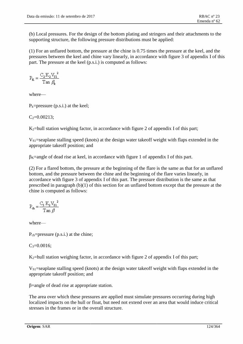
Data da emissão: 11 de setembro de 2017 RBAC nº 23
Emenda nº 62
Origem: SAR 124/364
(b) Local pressures. For the design of the bottom plating and stringers and their attachments to the
supporting structure, the following pressure distributions must be applied:
(1) For an unflared bottom, the pressure at the chine is 0.75 times the pressure at the keel, and the
pressures between the keel and chine vary linearly, in accordance with figure 3 of appendix I of this
part. The pressure at the keel (p.s.i.) is computed as follows:
where—
Pk=pressure (p.s.i.) at the keel;
C2=0.00213;
K2=hull station weighing factor, in accordance with figure 2 of appendix I of this part;
VS1=seaplane stalling speed (knots) at the design water takeoff weight with flaps extended in the
appropriate takeoff position; and
βK=angle of dead rise at keel, in accordance with figure 1 of appendix I of this part.
(2) For a flared bottom, the pressure at the beginning of the flare is the same as that for an unflared
bottom, and the pressure between the chine and the beginning of the flare varies linearly, in
accordance with figure 3 of appendix I of this part. The pressure distribution is the same as that
prescribed in paragraph (b)(1) of this section for an unflared bottom except that the pressure at the
chine is computed as follows:
where—
Pch=pressure (p.s.i.) at the chine;
C3=0.0016;
K2=hull station weighing factor, in accordance with figure 2 of appendix I of this part;
VS1=seaplane stalling speed (knots) at the design water takeoff weight with flaps extended in the
appropriate takeoff position; and
β=angle of dead rise at appropriate station.
The area over which these pressures are applied must simulate pressures occurring during high
localized impacts on the hull or float, but need not extend over an area that would induce critical
stresses in the frames or in the overall structure.

Data da emissão: 11 de setembro de 2017 RBAC nº 23
Emenda nº 62
Origem: SAR 125/364
(c) Distributed pressures. For the design of the frames, keel, and chine structure, the following
pressure distributions apply:
(1) Symmetrical pressures are computed as follows:
where—
P=pressure (p.s.i.);
C4=0.078 C1(with C1computed under §23.527);
K2=hull station weighing factor, determined in accordance with figure 2 of appendix I of this part;
VS0=seaplane stalling speed (knots) with landing flaps extended in the appropriate position and with
no slipstream effect; and
β=angle of dead rise at appropriate station.
(2) The unsymmetrical pressure distribution consists of the pressures prescribed in paragraph (c)(1)
of this section on one side of the hull or main float centerline and one-half of that pressure on the
other side of the hull or main float centerline, in accordance with figure 3 of appendix I of this part.
(3) These pressures are uniform and must be applied simultaneously over the entire hull or main
float bottom. The loads obtained must be carried into the sidewall structure of the hull proper, but
need not be transmitted in a fore and aft direction as shear and bending loads.
[Doc. No. 26269, 58 FR 42161, Aug. 6, 1993; 58 FR 51970, Oct. 5, 1993]
§ 23.535 Auxiliary float loads.
(a) General. Auxiliary floats and their attachments and supporting structures must be designed for
the conditions prescribed in this section. In the cases specified in paragraphs (b) through (e) of this
section, the prescribed water loads may be distributed over the float bottom to avoid excessive local
loads, using bottom pressures not less than those prescribed in paragraph (g) of this section.
(b) Step loading. The resultant water load must be applied in the plane of symmetry of the float at a
point three-fourths of the distance from the bow to the step and must be perpendicular to the keel.
The resultant limit load is computed as follows, except that the value of L need not exceed three
times the weight of the displaced water when the float is completely submerged:
where—

Data da emissão: 11 de setembro de 2017 RBAC nº 23
Emenda nº 62
Origem: SAR 126/364
L=limit load (lbs.);
C5=0.0053;
VS0=seaplane stalling speed (knots) with landing flaps extended in the appropriate position and with
no slipstream effect;
W=seaplane design landing weight in pounds;
βs=angle of dead rise at a station3/4of the distance from the bow to the step, but need not be less
than 15 degrees; and
ry=ratio of the lateral distance between the center of gravity and the plane of symmetry of the float
to the radius of gyration in roll.
(c) Bow loading. The resultant limit load must be applied in the plane of symmetry of the float at a
point one-fourth of the distance from the bow to the step and must be perpendicular to the tangent
to the keel line at that point. The magnitude of the resultant load is that specified in paragraph (b) of
this section.
(d) Unsymmetrical step loading. The resultant water load consists of a component equal to 0.75
times the load specified in paragraph (a) of this section and a side component equal to 0.025 tan β
times the load specified in paragraph (b) of this section. The side load must be applied
perpendicularly to the plane of symmetry of the float at a point midway between the keel and the
chine.
(e) Unsymmetrical bow loading. The resultant water load consists of a component equal to 0.75
times the load specified in paragraph (b) of this section and a side component equal to 0.25 tan β
times the load specified in paragraph (c) of this section. The side load must be applied
perpendicularly to the plane of symmetry at a point midway between the keel and the chine.
(f) Immersed float condition. The resultant load must be applied at the centroid of the cross section
of the float at a point one-third of the distance from the bow to the step. The limit load components
are as follows:
where—
P=mass density of water (slugs/ft.3 )
V=volume of float (ft.3 );
CX=coefficient of drag force, equal to 0.133;

Data da emissão: 11 de setembro de 2017 RBAC nº 23
Emenda nº 62
Origem: SAR 127/364
Cy=coefficient of side force, equal to 0.106;
K=0.8, except that lower values may be used if it is shown that the floats are incapable of
submerging at a speed of 0.8 Vsoin normal operations;
Vso=seaplane stalling speed (knots) with landing flaps extended in the appropriate position and with
no slipstream effect; and
g=acceleration due to gravity (ft/sec2 ).
(g) Float bottom pressures. The float bottom pressures must be established under §23.533, except
that the value of K2in the formulae may be taken as 1.0. The angle of dead rise to be used in
determining the float bottom pressures is set forth in paragraph (b) of this section.
[Doc. No. 26269, 58 FR 42162, Aug. 6, 1993; 58 FR 51970, Oct. 5, 1993]
§ 23.537 Seawing loads.
Seawing design loads must be based on applicable test data.
[Doc. No. 26269, 58 FR 42163, Aug. 6, 1993]
Emergency Landing Conditions
23.561 General.
(a) The airplane, although it may be damaged
in emergency landing conditions, must be
designed as prescribed in this section to protect
each occupant under those conditions.
(b) The structure must be designed to give each
occupant every reasonable chance of escaping
serious injury when:
(1) Proper use is made of the seats, safety belts,
and shoulder harnesses provided for in the
design;
(2) The occupant experiences the static inertia
loads corresponding to the following ultimate
load factors:
(i) Upward, 3,0g for normal, utility, and
commuter category airplanes, or 4,5g for
acrobatic category airplanes;
(ii) Forward, 9,0g;
23.561 Geral.
(a) O avião, embora possa ser danificado em
pouso sob condições de emergência, deve ser
projetado como previsto nesta seção para
proteger cada ocupante sob tais condições.
(b) A estrutura deve ser projetada para permitir
a cada ocupante todas as chances razoáveis
para escapar de ferimentos graves quando:
(1) há utilização adequada dos assentos, cintos
de segurança e cintos de ombro previstos no
projeto;
(2) O ocupante experimenta as cargas estáticas
inerciais correspondentes aos fatores de cargas
finais:
(i) Para cima, 3,0g para aviões das categorias:
normal, utilidade e transporte regional ou 4,5g
para aviões da categoria acrobática;
(ii) Para frente, 9,0g;

Data da emissão: 11 de setembro de 2017 RBAC nº 23
Emenda nº 62
Origem: SAR 128/364
(iii) Sideward, 1,5g; and
(iv) Downward, 6,0g when certification to the
emergency exit provisions of paragraph
23.807(d)(4) is requested; and
(3) The items of mass within the cabin, that
could injure an occupant, experience the static
inertia loads corresponding to the following
ultimate load factors:
(i) Upward, 3,0g;
(ii) Forward, 18,0g; and
(iii) Sideward, 4,5g.
(c) Each airplane with retractable landing gear
must be designed to protect each occupant in a
landing:
(1) With the wheels retracted;
(2) With moderate descent velocity; and
(3) Assuming, in the absence of a more rational
analysis:
(i) A downward ultimate inertia force of 3 g;
and
(ii) A coefficient of friction of 0,5 at the
ground.
(d) If it is not established that a turnover is
unlikely during an emergency landing, the
structure must be designed to protect the
occupants in a complete turnover as follows:
(1) The likelihood of a turnover may be shown
by an analysis assuming the following
conditions:
(i) The most adverse combination of weight
and center of gravity position;
(ii) Longitudinal load factor of 9.0g;
(iii) Lateral, 1,5g; e
(iv) Para baixo, 6,0g quando é solicitada a
certificação de provisões de saída de
emergência do parágrafo 23.807(d)(4); e
(3) Os itens de massa dentro da cabine que
poderiam ferir um ocupante experimentam as
cargas estáticas de inércia correspondentes aos
seguintes fatores de cargas finais:
(i) Para cima, 3,0g;
(ii) Para frente, 18,0g; e
(iii) Lateral, 4,5g.
(c) Cada avião com trem de pouso retrátil deve
ser projetado para proteger cada ocupante em
um pouso:
(1) Com as rodas recolhidas;
(2) Com velocidade de descida moderada; e
(3) Assumindo, na falta de uma análise mais
aprofundada:
(i) Uma força de inércia final de 3g para baixo;
e
(ii) Um coeficiente de atrito de 0,5 no solo.
(d) Se não for estabelecido que uma rotação do
avião é improvável durante um pouso de
emergência a estrutura deve ser projetada para
proteger os ocupantes em uma rotação
completa da seguinte forma:
(1) A probabilidade de uma rotação pode ser
demonstrada por uma análise assumindo as
seguintes condições:
(i) A combinação mais adversa de peso e
posição do centro de gravidade;
(ii) Fator de carga longitudinal de 9,0g;

Data da emissão: 11 de setembro de 2017 RBAC nº 23
Emenda nº 62
Origem: SAR 129/364
(iii) Vertical load factor of 1,0g; and
(iv) For airplanes with tricycle landing gear,
the nose wheel strut failed with the nose
contacting the ground.
(2) For determining the loads to be applied to
the inverted airplane after a turnover, an
upward ultimate inertia load factor of 3,0g and
a coefficient of friction with the ground of 0,5
must be used.
(e) Except as provided in paragraph 23.787(c),
the supporting structure must be designed to
restrain, under loads up to those specified in
paragraph (b)(3) of this section, each item of
mass that could injure an occupant if it came
loose in a minor crash landing.
(1) For engines mounted inside the fuselage, aft
of the cabin, it must be shown by test or
analysis that the engine and attached
accessories, and the engine mounting structure:
(i) Can withstand a forward acting static
ultimate inertia load factor of 18,0 g plus the
maximum takeoff engine thrust; or
(ii) The airplane structure is designed to
preclude the engine and its attached accessories
from entering or protruding into the cabin
should the engine mounts fail.
(2) [Reserved]
(iii) Fator de carga vertical de 1,0g; e
(iv) Para aviões com trem de pouso do tipo
triciclo, o suporte da roda de nariz falhada com
o nariz tocando o solo.
(2) Para determinar as cargas a serem aplicadas
ao avião invertido após uma rotação, um fator
de carga de inércia final para cima de 3,0g e
um coeficiente de atrito com o solo de 0,5
devem ser utilizados.
(e) Exceto como previsto no parágrafo
23.787(c), a estrutura de suporte deve ser
projetada para restringir, sob cargas até aquelas
especificadas no parágrafo (b)(3) desta seção,
cada item de massa que poderia ferir um
ocupante se ele se soltasse em um pouso do
tipo minor crash.
(1) Para motores montados dentro da
fuselagem, atrás da cabine, deve ser
demonstrado por teste ou análise que o motor e
acessórios acoplados, e a estrutura de
montagem do motor:
(i) Podem suportar um fator de carga inercial
final atuando frontalmente de 18,0 g mais o
máximo empuxo do motor na decolagem; ou
(ii) A estrutura do avião é projetada para
impedir o motor e seus acessórios acoplados de
entrarem ou sobressaiam na cabine caso os
coxins do motor falhem.
(2) [Reservado]
[Doc. No. 4080, 29 FR 17955, Dec. 18, 1964, as amended by Amdt. 23-7, 34 FR 13090, Aug. 13,
1969; Amdt. 23-24, 52 FR 34745, Sept. 14, 1987; Amdt. 23-36, 53 FR 30812, Aug. 15, 1988;
Amdt. 23-46, 59 FR 25772, May 17, 1994; Amdt. 23-48, 61 FR 5147, Feb. 9, 1996; Amdt. 23-62,
76 FR 75756, Dec. 2, 2011]
[Resolução nº 446, de 06.09.2017]
23.562 Emergency landing dynamic
conditions.
(a) Each seat/restraint system for use in a
normal, utility, or acrobatic category airplane,
23.562 Condições dinâmicas para pouso de
emergência.
(a) Cada assento/sistema de retenção para uso
em aviões da categoria normal, utilidade ou

Data da emissão: 11 de setembro de 2017 RBAC nº 23
Emenda nº 62
Origem: SAR 130/364
or in a commuter category jet airplane, must be
designed to protect each occupant during an
emergency landing when:
(1) Proper use is made of seats, safety belts,
and shoulder harnesses provided for in the
design; and
(2) The occupant is exposed to the loads
resulting from the conditions prescribed in this
section.
(b) Except for those seat/restraint systems that
are required to meet paragraph (d) of this
section, each seat/restraint system for crew or
passenger occupancy in a normal, utility, or
acrobatic category airplane, or in a commuter
category jet airplane, must successfully
complete dynamic tests or be demonstrated by
rational analysis supported by dynamic tests, in
accordance with each of the following
conditions. These tests must be conducted with
an occupant simulated by an anthropomorphic
test dummy (ATD) defined by 49 CFR Part
572, Subpart B, or an ANAC-approved
equivalent, with a nominal weight of 170
pounds (77 kg) and seated in the normal
upright position.
(1) For the first test, the change in velocity may
not be less than 31 feet per second (34 km/h).
The seat/restraint system must be oriented in its
nominal position with respect to the airplane
and with the horizontal plane of the airplane
pitched up 60 degrees, with no yaw, relative to
the impact vector. For seat/restraint systems to
be installed in the first row of the airplane,
peak deceleration must occur in not more than
0,05 seconds after impact and must reach a
minimum of 19g. For all other seat/restraint
systems, peak deceleration must occur in not
more than 0,06 seconds after impact and must
reach a minimum of 15g.
(2) For the second test, the change in velocity
may not be less than 42 feet per second (45
km/h). The seat/restraint system must be
oriented in its nominal position with respect to
the airplane and with the vertical plane of the
acrobática, ou em um avião a jato da categoria
transporte regional, deve ser projetado para
proteger o ocupante durante um pouso de
emergência quando:
(1) É feito o uso apropriado dos assentos,
cintos de segurança, e cintos de ombro
providos no projeto; e
(2) O ocupante é exposto às cargas resultantes
das condições prescritas nesta seção.
(b) Exceto para aqueles assentos/sistemas de
retenção que são requeridos para cumprir o
parágrafo (d) desta seção, cada assento/sistema
de retenção para a ocupação da tripulação ou
passageiro em aviões da categoria normal,
utilidade ou acrobática, ou em um avião a jato
da categoria transporte regional, deve
completar os ensaios dinâmicos com sucesso
ou ser demonstrado por análise racional
suportada por ensaio dinâmico, de acordo com
cada uma das seguintes condições. Esses
ensaios devem ser conduzidos com um
ocupante simulado por um boneco
antropomórfico de ensaio (ATD) definido pelo
49 CFR part 572, Subpart B, ou um equivalente
aprovado pelo ANAC, com um peso nominal
de 170 libras (77 kg) e sentado na posição ereta
normal.
(1) Para o primeiro ensaio, a mudança na
velocidade não pode ser menor que 31 pés por
segundo (34 km/h). O assento/sistema de
retenção deve ser orientado na posição nominal
com relação ao avião e com o plano horizontal
do avião cabrado para cima 60 graus, sem
guinada, com relação ao vetor de impacto. Para
assentos/sistemas de retenção a serem
instalados na primeira fileira do avião, o pico
de desaceleração deve ocorrer em no máximo
0,05 segundo depois do impacto e deve atingir
um mínimo de 19g. Para os outros
assentos/sistemas de retenção, o pico de
desaceleração deve ocorrer em no máximo 0,06
segundo depois do impacto e deve atingir no
mínimo 15g.
(2) Para o segundo ensaio, a mudança na

Data da emissão: 11 de setembro de 2017 RBAC nº 23
Emenda nº 62
Origem: SAR 131/364
airplane yawed 10 degrees, with no pitch,
relative to the impact vector in a direction that
results in the greatest load on the shoulder
harness. For seat/restraint systems to be
installed in the first row of the airplane, peak
deceleration must occur in not more than 0.05
seconds after impact and must reach a
minimum of 26g. For all other seat/restraint
systems, peak deceleration must occur in not
more than 0,06 seconds after impact and must
reach a minimum of 21g.
(3) To account for floor warpage, the floor rails
or attachment devices used to attach the
seat/restraint system to the airframe structure
must be preloaded to misalign with respect to
each other by at least 10 degrees vertically (i.e.,
pitch out of parallel) and one of the rails or
attachment devices must be preloaded to
misalign by 10 degrees in roll prior to
conducting the test defined by paragraph (b)(2)
of this section.
(c) Compliance with the following
requirements must be shown during the
dynamic tests conducted in accordance with
paragraph (b) of this section:
(1) The seat/restraint system must restrain the
ATD although seat/restraint system
components may experience deformation,
elongation, displacement, or crushing intended
as part of the design.
(2) The attachment between the seat/restraint
system and the test fixture must remain intact,
although the seat structure may have deformed.
(3) Each shoulder harness strap must remain on
the ATD's shoulder during the impact.
(4) The safety belt must remain on the ATD's
pelvis during the impact.
(5) The results of the dynamic tests must show
that the occupant is protected from serious head
injury.
(i) When contact with adjacent seats, structure,
velocidade não pode ser menor que 42 pés por
segundo (45 km/h). O assento/sistema de
retenção deve ser orientado na posição nominal
com relação ao avião e com o plano vertical do
avião guinado 10 graus, sem arfagem, em
relação ao vetor de impacto na direção que
resulta na maior carga no cinto de ombro. Para
assentos/sistemas de retenção a serem
instalados na primeira fileira do avião, o pico
de desaceleração deve ocorrer em no máximo
0,05 segundos depois do impacto e deve atingir
26g. Para os outros assentos/sistemas de
retenção, o pico de desaceleração deve ocorrer
em no máximo 0,06 segundo depois do
impacto e deve atingir no mínimo 21g.
(3) Para contar com o empenamento do piso, os
trilhos do piso ou dispositivos de fixação,
usados para fixar o assento/sistema de retenção
à estrutura da célula, devem ser pré-carregados
para desalinharem entre si pelo menos 10 graus
verticalmente (por exemplo: arfagem sem
paralelismo) e um dos trilhos ou dispositivos de
fixação devem ser pré-carregados para se
desalinharem em 10 graus em rolagem antes de
conduzir o ensaio definido pelo parágrafo
(b)(2).
(c) Cumprimento com os seguintes requisitos
deve se demonstrado durante os ensaios
dinâmicos conduzidos de acordo com o
parágrafo (b) desta seção:
(1) O assento/sistema de retenção deve
restringir o ATD apesar dos componentes do
assento/sistema de retenção poderem sofrer
deformação, alongamento, deslocamento ou
esmagamento previstos no projeto.
(2) A ligação entre o assento/sistema de
retenção e os dispositivos de ensaio deve
permanecer intacta, apesar da estrutura do
assento poder se deformar.
(3) Cada fita do cinto de ombro deve
permanecer no ombro do ATD durante o
impacto.
(4) O cinto de segurança deve permanecer na

Data da emissão: 11 de setembro de 2017 RBAC nº 23
Emenda nº 62
Origem: SAR 132/364
or other items in the cabin can occur, protection
must be provided so that the head impact does
not exceed a head injury criteria (HIC) of
1.000.
(ii) The value of HIC is defined as:
Where:
t1 is the initial integration time, expressed in
seconds, t2 is the final integration time,
expressed in seconds, and a(t) is the total
acceleration vs. time curve for the head strike
expressed as a multiple of g (units of gravity).
(iii) Compliance with the HIC limit must be
demonstrated by measuring the head impact
during dynamic testing as prescribed in
paragraphs (b)(1) and (b)(2) of this section or
by a separate showing of compliance with the
head injury criteria using test or analysis
procedures.
(6) Loads in individual shoulder harness straps
may not exceed 1.750 pounds (7.784 N). If
dual straps are used for retaining the upper
torso, the total strap loads may not exceed
2.000 pounds (8.896 N).
(7) The compression load measured between
the pelvis and the lumbar spine of the ATD
may not exceed 1.500 pounds (6.672 N).
(d) For all single-engine airplanes with a
VSOof more than 61 knots at maximum
weight, and those multiengine airplanes of
6.000 pounds (2.722 kg) or less maximum
weight with a VSO of more than 61 knots at
maximum weight that do not comply with
paragraph 23.67(a)(1);
(1) The ultimate load factors of paragraph
23.561(b) must be increased by multiplying the
load factors by the square of the ratio of the
increased stall speed to 61 knots. The increased
pélvis do ATD durante o impacto.
(5) O resultado do ensaio dinâmico deve
mostrar que o ocupante é protegido de danos
sérios à cabeça.
(i) Quando puder acontecer o contato com as
adjacências do assento, com a estrutura, ou
com outro item na cabine, deve ser provida
proteção para que o impacto da cabeça não
exceda o critério de dano à cabeça (HIC) de
1.000.
(ii) O valor do HIC é definido como:
Onde:
t1 é o tempo inicial de integração, expresso em
segundos, t2 é o tempo final de integração,
expresso em segundos, (t2− t1) é o tempo de
duração do maior impacto de cabeça, expresso
em segundos, e a(t) é a aceleração resultante do
centro de gravidade da cabeça expresso na
forma de múltiplos de g (unidades de
gravidade).
(iii) Cumprimento com o limite de HIC deve
ser demonstrado por medida do impacto de
cabeça durante o ensaio dinâmico como
prescrito nos parágrafos (b)(1) e (b)(2) desta
seção ou por uma demonstração de
cumprimento separada com o critério de dano à
cabeça usando ensaio ou procedimentos de
análises.
(6) Cargas em tiras individuais do cinto de
ombro não podem exceder 1.750 libras (7.784
N). Se forem usadas tiras duplas para reter o
torso superior, as cargas totais nas tiras não
podem exceder 2.000 libras (8.896 N).
(7) A carga de compressão medida entre a
pélvis e a espinha lombar do ATD não pode
exceder 1.500 libras (6.672 N).

Data da emissão: 11 de setembro de 2017 RBAC nº 23
Emenda nº 62
Origem: SAR 133/364
ultimate load factors need not exceed the
values reached at a VS0of 79 knots. The
upward ultimate load factor for acrobatic
category airplanes need not exceed 5.0g.
(2) The seat/restraint system test required by
paragraph (b)(1) of this section must be
conducted in accordance with the following
criteria:
(i) The change in velocity may not be less than
31 feet per second.
(ii)(A) The peak deceleration (gp) of 19g and
15g must be increased and multiplied by the
square of the ratio of the increased stall speed
to 61 knots:
gp=19.0 (VS0/61)2 or gp=15.0 (VS0/61)2
(B) The peak deceleration need not exceed the
value reached at a VS0 of 79 knots.
(iii) The peak deceleration must occur in not
more than time (tr), which must be computed as
follows:
where:
gp = The peak deceleration calculated in
accordance with paragraph (d)(2)(ii) of this
section
tr = The rise time (in seconds) to the peak
deceleration.
(e) An alternate approach that achieves an
equivalent, or greater, level of occupant
protection to that required by this section may
be used if substantiated on a rational basis.
(d) Para todo avião monomotor com a Vso
maior que 61 nós no peso máximo, e aqueles
aviões multimotores com 6.000 libras (2.722
kg) ou menor peso máximo com a Vso maior
que 61 nós no máximo peso que não cumpre
com o parágrafo 23.67(a)(1);
(1) O fator de carga final do parágrafo 23.561
(b) deve ser aumentado pela multiplicação do
fator de carga pelo quadrado da razão do
incremento da velocidade de estol para 61nós.
O fator de carga final não precisa exceder os
valores atingidos até a Vso de 79 nós. O fator
de carga final para cima para aviões da
categoria acrobática não precisa exceder 5,0 g.
(2) O ensaio do assento/sistema de retenção
requerido pelo parágrafo (b)(1) desta seção
deve ser conduzido de acordo com o seguinte
critério:
(i) A mudança de velocidade não pode ser
menor que 31 pés por segundo (34km/h).
(ii)(A) O pico de desaceleração (gp) de 19g e
15g deve ser aumentado e multiplicado pelo
quadrado da razão de incremento da velocidade
de estol até 61 nós:
gp = 19,0(Vso/61)2 ou gp = 15,0(Vso/61)2
(B) O pico de desaceleração não necessita
exceder o valor atingido em uma VS0 de 79 nós.
(iii) O pico de desaceleração deve ocorrer em
no máximo (tr), o qual deve ser computado
como segue:
Onde:
gp = O pico de desaceleração calculado de
acordo com o parágrafo (d)(2)(ii) desta seção
tr = O tempo de aumento do tempo (em
segundos) até o pico de desaceleração.

Data da emissão: 11 de setembro de 2017 RBAC nº 23
Emenda nº 62
Origem: SAR 134/364
(e) Uma aproximação alternativa que alcance
um nível de proteção ao ocupante equivalente,
ou maior, àquele requerido por esta seção pode
ser usada se substanciada numa base racional.
[Amdt. 23-36, 53 FR 30812, Aug. 15, 1988, as amended by Amdt. 23-44, 58 FR 38639, July 19,
1993; Amdt. 23-50, 61 FR 5192, Feb. 9, 1996; Amdt. 23-62, 76 FR 75756, Dec. 2, 2011]
[Resolução nº 446, de 06.09.2017]
Fatigue Evaluation
23.571 Metallic pressurized cabin
structures.
For normal, utility, and acrobatic category
airplanes, the strength, detail design, and
fabrication of the metallic structure of the
pressure cabin must be evaluated under
paragraphs (a), (b), or (c). In addition, the
requirements of paragraph (d) must be met
when applicable.
(a) A fatigue strength investigation in which
the structure is shown by tests, or by analysis
supported by test evidence, to be able to
withstand the repeated loads of variable
magnitude expected in service; or
(b) A fail safe strength investigation, in which
it is shown by analysis, tests, or both that
catastrophic failure of the structure is not
probable after fatigue failure, or obvious partial
failure, of a principal structural element, and
that the remaining structures are able to
withstand a static ultimate load factor of 75
percent of the limit load factor at VC,
considering the combined effects of normal
operating pressures, expected external
aerodynamic pressures, and flight loads. These
loads must be multiplied by a factor of 1.15
unless the dynamic effects of failure under
static load are otherwise considered.
(c) The damage tolerance evaluation of
paragraph 23.573(b).
(d) If certification for operation above 41.000
feet is requested, a damage tolerance evaluation
of the fuselage pressure boundary per
23.571 Estruturas metálicas da cabine
pressurizada.
Para aviões das categorias normal, utilidade e
acrobática, a resistência, as características de
projeto e a fabricação de estruturas metálicas
empregadas na cabine pressurizada devem ser
avaliadas sob os parágrafos (a), (b) ou (c).
Além disso, os requisitos do parágrafo (d)
devem ser cumpridos quando aplicável.
(a) Deve-se fazer uma investigação da
resistência a fadiga da estrutura a fim de
demonstrar que ela é capaz de resistir a cargas
repetitivas de magnitude variável esperadas
ocorrerem em serviço. Esta investigação deve
ser realizada através de ensaios, ou por análises
suportadas por evidências de ensaios; ou
(b) Deve-se fazer uma investigação da
resistência à falha segura (fail safe), através de
análises, ensaios, ou ambos, a fim de
demonstrar que não é provável a ocorrência de
uma falha catastrófica da estrutura após uma
falha por fadiga, ou após uma falha parcial
óbvia, de um elemento estrutural principal, e
que as estruturas remanescentes são capazes de
resistir a um fator de carga estática final de 75
porcento do fator de carga limite na VC,
considerando os efeitos combinados das
pressões normais de operação, pressões
aerodinâmicas externas esperadas e cargas de
voo. Estas cargas devem ser multiplicadas por
um fator de 1.15 a menos que os efeitos
dinâmicos da falha sob carga estática sejam
considerados de alguma outra maneira.
(c) Uma avaliação de tolerância ao dano

Data da emissão: 11 de setembro de 2017 RBAC nº 23
Emenda nº 62
Origem: SAR 135/364
paragraph 23.573(b) must be conducted. conforme o parágrafo 23.573(b).
(d) Se for solicitada certificação para operação
acima de 41.000 pés, uma avaliação de
tolerância a dano da fronteira da fuselagem
sujeita a pressurização, de acordo com o
parágrafo 23.573(b), deve ser conduzida.
[Doc. No. 4080, 29 FR 17955, Dec. 18, 1964, as amended by Amdt. 23-14, 38 FR 31821, Nov. 19,
1973; Amdt. 23-45, 58 FR 42163, Aug. 6, 1993; Amdt. 23-48, 61 FR 5147, Feb. 9, 1996; Amdt. 23-
62, 76 FR 75756, Dec. 2, 2011]
[Resolução nº 446, de 06.09.2017]
§ 23.572 Metallic wing, empennage, and associated structures.
(a) For normal, utility, and acrobatic category airplanes, the strength, detail design, and fabrication
of those parts of the airframe structure whose failure would be catastrophic must be evaluated under
one of the following unless it is shown that the structure, operating stress level, materials and
expected uses are comparable, from a fatigue standpoint, to a similar design that has had extensive
satisfactory service experience:
(1) A fatigue strength investigation in which the structure is shown by tests, or by analysis
supported by test evidence, to be able to withstand the repeated loads of variable magnitude
expected in service; or
(2) A fail-safe strength investigation in which it is shown by analysis, tests, or both, that
catastrophic failure of the structure is not probable after fatigue failure, or obvious partial failure, of
a principal structural element, and that the remaining structure is able to withstand a static ultimate
load factor of 75 percent of the critical limit load factor at V c.These loads must be multiplied by a
factor of 1.15 unless the dynamic effects of failure under static load are otherwise considered.
(3) The damage tolerance evaluation of §23.573(b).
(b) Each evaluation required by this section must—
(1) Include typical loading spectra (e.g. taxi, ground-air-ground cycles, maneuver, gust);
(2) Account for any significant effects due to the mutual influence of aerodynamic surfaces; and
(3) Consider any significant effects from propeller slipstream loading, and buffet from vortex
impingements.
[Amdt. 23–7, 34 FR 13090, Aug. 13, 1969, as amended by Amdt. 23–14, 38 FR 31821, Nov. 19,
1973; Amdt. 23–34, 52 FR 1830, Jan. 15, 1987; Amdt. 23–38, 54 FR 39511, Sept. 26, 1989; Amdt.
23–45, 58 FR 42163, Aug. 6, 1993; Amdt. 23–48, 61 FR 5147, Feb. 9, 1996]
§ 23.573 Damage tolerance and fatigue evaluation of structure.
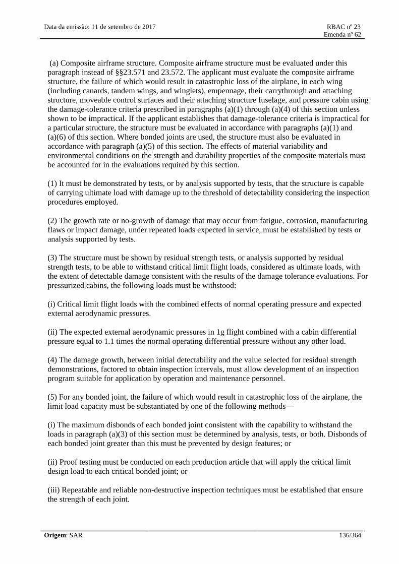
Data da emissão: 11 de setembro de 2017 RBAC nº 23
Emenda nº 62
Origem: SAR 136/364
(a) Composite airframe structure. Composite airframe structure must be evaluated under this
paragraph instead of §§23.571 and 23.572. The applicant must evaluate the composite airframe
structure, the failure of which would result in catastrophic loss of the airplane, in each wing
(including canards, tandem wings, and winglets), empennage, their carrythrough and attaching
structure, moveable control surfaces and their attaching structure fuselage, and pressure cabin using
the damage-tolerance criteria prescribed in paragraphs (a)(1) through (a)(4) of this section unless
shown to be impractical. If the applicant establishes that damage-tolerance criteria is impractical for
a particular structure, the structure must be evaluated in accordance with paragraphs (a)(1) and
(a)(6) of this section. Where bonded joints are used, the structure must also be evaluated in
accordance with paragraph (a)(5) of this section. The effects of material variability and
environmental conditions on the strength and durability properties of the composite materials must
be accounted for in the evaluations required by this section.
(1) It must be demonstrated by tests, or by analysis supported by tests, that the structure is capable
of carrying ultimate load with damage up to the threshold of detectability considering the inspection
procedures employed.
(2) The growth rate or no-growth of damage that may occur from fatigue, corrosion, manufacturing
flaws or impact damage, under repeated loads expected in service, must be established by tests or
analysis supported by tests.
(3) The structure must be shown by residual strength tests, or analysis supported by residual
strength tests, to be able to withstand critical limit flight loads, considered as ultimate loads, with
the extent of detectable damage consistent with the results of the damage tolerance evaluations. For
pressurized cabins, the following loads must be withstood:
(i) Critical limit flight loads with the combined effects of normal operating pressure and expected
external aerodynamic pressures.
(ii) The expected external aerodynamic pressures in 1g flight combined with a cabin differential
pressure equal to 1.1 times the normal operating differential pressure without any other load.
(4) The damage growth, between initial detectability and the value selected for residual strength
demonstrations, factored to obtain inspection intervals, must allow development of an inspection
program suitable for application by operation and maintenance personnel.
(5) For any bonded joint, the failure of which would result in catastrophic loss of the airplane, the
limit load capacity must be substantiated by one of the following methods—
(i) The maximum disbonds of each bonded joint consistent with the capability to withstand the
loads in paragraph (a)(3) of this section must be determined by analysis, tests, or both. Disbonds of
each bonded joint greater than this must be prevented by design features; or
(ii) Proof testing must be conducted on each production article that will apply the critical limit
design load to each critical bonded joint; or
(iii) Repeatable and reliable non-destructive inspection techniques must be established that ensure
the strength of each joint.
Data da emissão: 11 de setembro de 2017 RBAC nº 23
Emenda nº 62
Origem: SAR 137/364
(6) Structural components for which the damage tolerance method is shown to be impractical must
be shown by component fatigue tests, or analysis supported by tests, to be able to withstand the
repeated loads of variable magnitude expected in service. Sufficient component, subcomponent,
element, or coupon tests must be done to establish the fatigue scatter factor and the environmental
effects. Damage up to the threshold of detectability and ultimate load residual strength capability
must be considered in the demonstration.
(b) Metallic airframe structure . If the applicant elects to use §23.571(c) or §23.572(a)(3), then the
damage tolerance evaluation must include a determination of the probable locations and modes of
damage due to fatigue, corrosion, or accidental damage. Damage at multiple sites due to fatigue
must be included where the design is such that this type of damage can be expected to occur. The
evaluation must incorporate repeated load and static analyses supported by test evidence. The extent
of damage for residual strength evaluation at any time within the operational life of the airplane
must be consistent with the initial detectability and subsequent growth under repeated loads. The
residual strength evaluation must show that the remaining structure is able to withstand critical limit
flight loads, considered as ultimate, with the extent of detectable damage consistent with the results
of the damage tolerance evaluations. For pressurized cabins, the following load must be withstood:
(1) The normal operating differential pressure combined with the expected external aerodynamic
pressures applied simultaneously with the flight loading conditions specified in this part, and
(2) The expected external aerodynamic pressures in 1g flight combined with a cabin differential
pressure equal to 1.1 times the normal operating differential pressure without any other load.
[Doc. No. 26269, 58 FR 42163, Aug. 6, 1993; 58 FR 51970, Oct. 5, 1993, as amended by Amdt.
23–48, 61 FR 5147, Feb. 9, 1996; 73 FR 19746, Apr. 11, 2008]
§ 23.574 Metallic damage tolerance and fatigue evaluation of commuter category airplanes.
For commuter category airplanes—
(a) Metallic damage tolerance. An evaluation of the strength, detail design, and fabrication must
show that catastrophic failure due to fatigue, corrosion, defects, or damage will be avoided
throughout the operational life of the airplane. This evaluation must be conducted in accordance
with the provisions of §23.573, except as specified in paragraph (b) of this section, for each part of
the structure that could contribute to a catastrophic failure.
(b) Fatigue (safe-life) evaluation. Compliance with the damage tolerance requirements of paragraph
(a) of this section is not required if the applicant establishes that the application of those
requirements is impractical for a particular structure. This structure must be shown, by analysis
supported by test evidence, to be able to withstand the repeated loads of variable magnitude
expected during its service life without detectable cracks. Appropriate safe-life scatter factors must
be applied.
[Doc. No. 27805, 61 FR 5148, Feb. 9, 1996]
§ 23.575 Inspections and other procedures.
Each inspection or other procedure, based on an evaluation required by §§23.571, 23.572, 23.573 or

Data da emissão: 11 de setembro de 2017 RBAC nº 23
Emenda nº 62
Origem: SAR 138/364
23.574, must be established to prevent catastrophic failure and must be included in the Limitations
Section of the Instructions for Continued Airworthiness required by §23.1529.
[Doc. No. 27805, 61 FR 5148, Feb. 9, 1996]
Subpart D—Design and Construction
§ 23.601 General.
The suitability of each questionable design detail and part having an important bearing on safety in
operations, must be established by tests.
§ 23.603 Materials and workmanship.
(a) The suitability and durability of materials used for parts, the failure of which could adversely
affect safety, must—
(1) Be established by experience or tests;
(2) Meet approved specifications that ensure their having the strength and other properties assumed
in the design data; and
(3) Take into account the effects of environmental conditions, such as temperature and humidity,
expected in service.
(b) Workmanship must be of a high standard.
[Doc. No. 4080, 29 FR 17955, Dec. 18, 1964, as amended by Amdt. 23–17, 41 FR 55464, Dec. 20,
1976; Amdt. 23–23, 43 FR 50592, Oct. 10, 1978]
§ 23.605 Fabrication methods.
(a) The methods of fabrication used must produce consistently sound structures. If a fabrication
process (such as gluing, spot welding, or heat-treating) requires close control to reach this objective,
the process must be performed under an approved process specification.
(b) Each new aircraft fabrication method must be substantiated by a test program.
[Doc. No. 4080, 29 FR 17955, Dec. 18, 1964; 30 FR 258, Jan. 9, 1965, as amended by Amdt. 23–
23, 43 FR 50592, Oct. 10, 1978]
§ 23.607 Fasteners.
(a) Each removable fastener must incorporate two retaining devices if the loss of such fastener
would preclude continued safe flight and landing.
(b) Fasteners and their locking devices must not be adversely affected by the environmental
conditions associated with the particular installation.

Data da emissão: 11 de setembro de 2017 RBAC nº 23
Emenda nº 62
Origem: SAR 139/364
(c) No self-locking nut may be used on any bolt subject to rotation in operation unless a non-friction
locking device is used in addition to the self-locking device.
[Doc. No. 27805, 61 FR 5148, Feb. 9, 1996]
§ 23.609 Protection of structure.
Each part of the structure must—
(a) Be suitably protected against deterioration or loss of strength in service due to any cause,
including—
(1) Weathering;
(2) Corrosion; and
(3) Abrasion; and
(b) Have adequate provisions for ventilation and drainage.
§ 23.611 Accessibility provisions.
For each part that requires maintenance, inspection, or other servicing, appropriate means must be
incorporated into the aircraft design to allow such servicing to be accomplished.
[Doc. No. 27805, 61 FR 5148, Feb. 9, 1996]
§ 23.613 Material strength properties and design values.
(a) Material strength properties must be based on enough tests of material meeting specifications to
establish design values on a statistical basis.
(b) Design values must be chosen to minimize the probability of structural failure due to material
variability. Except as provided in paragraph (e) of this section, compliance with this paragraph must
be shown by selecting design values that ensure material strength with the following probability:
(1) Where applied loads are eventually distributed through a single member within an assembly, the
failure of which would result in loss of structural integrity of the component; 99 percent probability
with 95 percent confidence.
(2) For redundant structure, in which the failure of individual elements would result in applied loads
being safely distributed to other load carrying members; 90 percent probability with 95 percent
confidence.
(c) The effects of temperature on allowable stresses used for design in an essential component or
structure must be considered where thermal effects are significant under normal operating
conditions.
(d) The design of the structure must minimize the probability of catastrophic fatigue failure,

Data da emissão: 11 de setembro de 2017 RBAC nº 23
Emenda nº 62
Origem: SAR 140/364
particularly at points of stress concentration.
(e) Design values greater than the guaranteed minimums required by this section may be used
where only guaranteed minimum values are normally allowed if a “premium selection” of the
material is made in which a specimen of each individual item is tested before use to determine that
the actual strength properties of that particular item will equal or exceed those used in design.
[Doc. No. 4080, 29 FR 17955, Dec. 18, 1964; 30 FR 258, Jan. 9, 1965, as amended by Amdt. 23–
23, 43 FR 50592, Oct. 30, 1978; Amdt. 23–45, 58 FR 42163, Aug. 6, 1993]
§ 23.619 Special factors.
The factor of safety prescribed in §23.303 must be multiplied by the highest pertinent special
factors of safety prescribed in §§23.621 through 23.625 for each part of the structure whose strength
is—
(a) Uncertain;
(b) Likely to deteriorate in service before normal replacement; or
(c) Subject to appreciable variability because of uncertainties in manufacturing processes or
inspection methods.
[Amdt. 23–7, 34 FR 13091, Aug. 13, 1969]
§ 23.621 Casting factors.
(a) General. The factors, tests, and inspections specified in paragraphs (b) through (d) of this section
must be applied in addition to those necessary to establish foundry quality control. The inspections
must meet approved specifications. Paragraphs (c) and (d) of this section apply to any structural
castings except castings that are pressure tested as parts of hydraulic or other fluid systems and do
not support structural loads.
(b) Bearing stresses and surfaces. The casting factors specified in paragraphs (c) and (d) of this
section—
(1) Need not exceed 1.25 with respect to bearing stresses regardless of the method of inspection
used; and
(2) Need not be used with respect to the bearing surfaces of a part whose bearing factor is larger
than the applicable casting factor.
(c) Critical castings. For each casting whose failure would preclude continued safe flight and
landing of the airplane or result in serious injury to occupants, the following apply:
(1) Each critical casting must either—
(i) Have a casting factor of not less than 1.25 and receive 100 percent inspection by visual,
radiographic, and either magnetic particle, penetrant or other approved equivalent non-destructive

Data da emissão: 11 de setembro de 2017 RBAC nº 23
Emenda nº 62
Origem: SAR 141/364
inspection method; or
(ii) Have a casting factor of not less than 2.0 and receive 100 percent visual inspection and 100
percent approved non-destructive inspection. When an approved quality control procedure is
established and an acceptable statistical analysis supports reduction, non-destructive inspection may
be reduced from 100 percent, and applied on a sampling basis.
(2) For each critical casting with a casting factor less than 1.50, three sample castings must be static
tested and shown to meet—
(i) The strength requirements of §23.305 at an ultimate load corresponding to a casting factor of
1.25; and
(ii) The deformation requirements of §23.305 at a load of 1.15 times the limit load.
(3) Examples of these castings are structural attachment fittings, parts of flight control systems,
control surface hinges and balance weight attachments, seat, berth, safety belt, and fuel and oil tank
supports and attachments, and cabin pressure valves.
(d) Non-critical castings. For each casting other than those specified in paragraph (c) or (e) of this
section, the following apply:
(1) Except as provided in paragraphs (d)(2) and (3) of this section, the casting factors and
corresponding inspections must meet the following table:
Casting factor Inspection
2.0 or more 100 percent visual.
Less than 2.0 but
more than 1.5
100 percent visual, and magnetic particle or penetrant or equivalent
nondestructive inspection methods.
1.25 through 1.50 100 percent visual, magnetic particle or penetrant, and radiographic, or
approved equivalent nondestructive inspection methods.
(2) The percentage of castings inspected by nonvisual methods may be reduced below that specified
in subparagraph (d)(1) of this section when an approved quality control procedure is established.
(3) For castings procured to a specification that guarantees the mechanical properties of the material
in the casting and provides for demonstration of these properties by test of coupons cut from the
castings on a sampling basis—
(i) A casting factor of 1.0 may be used; and
(ii) The castings must be inspected as provided in paragraph (d)(1) of this section for casting factors
of “1.25 through 1.50” and tested under paragraph (c)(2) of this section.
(e) Non-structural castings. Castings used for non-structural purposes do not require evaluation,
testing or close inspection.
Data da emissão: 11 de setembro de 2017 RBAC nº 23
Emenda nº 62
Origem: SAR 142/364
[Doc. No. 4080, 29 FR 17955, Dec. 18, 1964, as amended by Amdt. 23–45, 58 FR 42164, Aug. 6,
1993]
§ 23.623 Bearing factors.
(a) Each part that has clearance (free fit), and that is subject to pounding or vibration, must have a
bearing factor large enough to provide for the effects of normal relative motion.
(b) For control surface hinges and control system joints, compliance with the factors prescribed in
§§23.657 and 23.693, respectively, meets paragraph (a) of this section.
[Amdt. 23–7, 34 FR 13091, Aug. 13, 1969]
§ 23.625 Fitting factors.
For each fitting (a part or terminal used to join one structural member to another), the following
apply:
(a) For each fitting whose strength is not proven by limit and ultimate load tests in which actual
stress conditions are simulated in the fitting and surrounding structures, a fitting factor of at least
1.15 must be applied to each part of—
(1) The fitting;
(2) The means of attachment; and
(3) The bearing on the joined members.
(b) No fitting factor need be used for joint designs based on comprehensive test data (such as
continuous joints in metal plating, welded joints, and scarf joints in wood).
(c) For each integral fitting, the part must be treated as a fitting up to the point at which the section
properties become typical of the member.
(d) For each seat, berth, safety belt, and harness, its attachment to the structure must be shown, by
analysis, tests, or both, to be able to withstand the inertia forces prescribed in §23.561 multiplied by
a fitting factor of 1.33.
[Doc. No. 4080, 29 FR 17955, Dec. 18, 1964, as amended by Amdt. 23–7, 34 FR 13091, Aug. 13,
1969]
§ 23.627 Fatigue strength.
The structure must be designed, as far as practicable, to avoid points of stress concentration where
variable stresses above the fatigue limit are likely to occur in normal service.
23.629 Flutter.
(a) It must be shown by the methods of
23.629 Flutter.
(a) Deve ser mostrado pelos métodos do
Data da emissão: 11 de setembro de 2017 RBAC nº 23
Emenda nº 62
Origem: SAR 143/364
paragraph (b) and either paragraph (c) or (d) of
this section, that the airplane is free from
flutter, control reversal, and divergence for any
condition of operation within the limit V-n
envelope and at all speeds up to the speed
specified for the selected method. In addition:
(1) Adequate tolerances must be established for
quantities which affect flutter, including speed,
damping, mass balance, and control system
stiffness; and
(2) The natural frequencies of main structural
components must be determined by vibration
tests or other approved methods.
(b) Flight flutter tests must be made to show
that the airplane is free from flutter, control
reversal and divergence and to show that:
(1) Proper and adequate attempts to induce
flutter have been made within the speed range
up to VD/MD, or VDF/MDF for jets;
(2) The vibratory response of the structure
during the test indicates freedom from flutter;
(3) A proper margin of damping exists at
VD/MD, or VDF/MDF for jets; and
(4) As VD/MD (or VDF/MDF for jets) is
approached, there is no large and rapid
reduction in damping.
(c) Any rational analysis used to predict
freedom from flutter, control reversal and
divergence must cover all speeds up to 1,2
VD/1,2 MD, limited to Mach 1,0 for subsonic
airplanes.
(d) Compliance with the rigidity and mass
balance criteria (pages 4–12), in Airframe and
Equipment Engineering Report No. 45 (as
corrected) “Simplified Flutter Prevention
Criteria” (published by the Federal Aviation
Administration) may be accomplished to show
that the airplane is free from flutter, control
reversal, or divergence if:
parágrafo (b) e também pelos parágrafos (c) ou
(d) desta seção, que o avião é livre de flutter,
reversão de comandos e divergência para
qualquer condição de operação dentro dos
limites do envelope V-n e em todas velocidades
até a velocidade especificada pelo método
selecionado. Em adição:
(1) Tolerâncias adequadas devem ser
estabelecidas para as quantidades que afetam o
flutter, incluindo velocidade, amortecimento,
massa de balanceamento, e rigidez do sistema
de controle; e
(2) As frequências naturais dos principais
componentes estruturais devem ser
determinadas por ensaios de vibração ou outros
métodos aprovados.
(b) Ensaios em voo para flutter devem ser
feitos para mostrar que o avião é livre de
flutter, reversão de comandos e divergência, e
para mostrar que:
(1) Tentativas adequadas e apropriadas para
induzir o flutter foram feitas dentro da faixa de
velocidade até a VD/MD, ou VDF/MDF para
jatos;
(2) A resposta vibratória da estrutura durante o
ensaio indica ausência de flutter;
(3) Uma margem apropriada de amortecimento
existe na VD/MD, ou VDF/MDF para jatos; e
(4) Como VD/MD (ou VDF/MDF para jatos) é
aproximada, não há redução grande e rápida no
amortecimento quando a VD se aproxima.
(c) Qualquer análise racional utilizada para
predizer ausência de flutter, reversão de
comandos e divergência deve cobrir todas as
velocidades até 1,2 VD/1,2 MD, limitada ao
Mach 1,0 para aviões subsônicos.
(d) Cumprimento com o critério de rigidez e
massa de balanceamento (páginas 4-12), em
“Airframe and Equipment Engineering Report”
No.45 (conforme corrigido) “Simplified Flutter
Data da emissão: 11 de setembro de 2017 RBAC nº 23
Emenda nº 62
Origem: SAR 144/364
(1) VD/MD for the airplane is less than 260
knots (EAS) and less than Mach 0,5,
(2) The wing and aileron flutter prevention
criteria, as represented by the wing torsional
stiffness and aileron balance criteria, are
limited in use to airplanes without large mass
concentrations (such as engines, floats, or fuel
tanks in outer wing panels) along the wing
span, and
(3) The airplane:
(i) Does not have a T-tail or other
unconventional tail configurations;
(ii) Does not have unusual mass distributions or
other unconventional design features that affect
the applicability of the criteria, and
(iii) Has fixed-fin and fixed-stabilizer surfaces.
(e) For turbopropeller-powered airplanes, the
dynamic evaluation must include:
(1) Whirl mode degree of freedom which takes
into account the stability of the plane of
rotation of the propeller and significant elastic,
inertial, and aerodynamic forces, and
(2) Propeller, engine, engine mount, and
airplane structure stiffness and damping
variations appropriate to the particular
configuration.
(f) Freedom from flutter, control reversal, and
divergence up to VD/MD must be shown as
follows:
(1) For airplanes that meet the criteria of
paragraphs (d)(1) through (d)(3) of this section,
after the failure, malfunction, or disconnection
of any single element in any tab control system.
(2) For airplanes other than those described in
paragraph (f)(1) of this section, after the
failure, malfunction, or disconnection of any
single element in the primary flight control
system, any tab control system, or any flutter
Prevention Criteria” (publicado pela Federal
Aviation Administration) pode ser feito para
mostrar que o avião é livre de flutter, reversão
de comandos, ou divergência se:
(1) VD/MD para o avião é menos do que 260
nós (EAS) e menos do que Mach 0,5,
(2) Os critérios de prevenção do flutter da asa e
do aileron, como representados pelos critérios
de rigidez torsional da asa e balanceamento do
aileron, são limitados na utilização em aviões
sem grandes concentrações de massas (tais
como motores, flutuadores, ou tanques de
combustíveis nos painéis mais externos da asa)
ao longo da longarina da asa, e
(3) O avião:
(i) Não tem configuração de cauda em T ou
outra configuração de cauda não convencional;
(ii) Não tem distribuição de massa não usual ou
outras características não convencionais que
afetam a aplicabilidade do critério, e
(iii) Tem superfícies das empenagens vertical e
horizontal fixas.
(e) Para aviões turbo hélice, a avaliação
dinâmica deve incluir:
(1) Grau de liberdade para o modo de whirl o
qual toma em conta a estabilidade do plano de
rotação da hélice e forças significantes
aerodinâmicas, elásticas e de inércia, e
(2) Hélice, motor, suporte do motor e variações
apropriadas de rigidez e amortecimento para a
configuração em particular.
(f) Ausência de flutter, reversão de comando, e
divergências até a VD/MD devem ser mostradas
como seguem:
(1) Para aviões que atendem os critérios dos
parágrafos (d)(1) ao (d)(3) desta seção, após a
falha, mau funcionamento, ou desconexão de
qualquer elemento simples em qualquer
Data da emissão: 11 de setembro de 2017 RBAC nº 23
Emenda nº 62
Origem: SAR 145/364
damper.
(g) For airplanes showing compliance with the
fail-safe criteria of sections 23.571 and 23.572,
the airplane must be shown by analysis to be
free from flutter up to VD/MD after fatigue
failure, or obvious partial failure, of a principal
structural element.
(h) For airplanes showing compliance with the
damage tolerance criteria of section 23.573, the
airplane must be shown by analysis to be free
from flutter up to VD/MD with the extent of
damage for which residual strength is
demonstrated.
(i) For modifications to the type design that
could affect the flutter characteristics,
compliance with paragraph (a) of this section
must be shown, except that analysis based on
previously approved data may be used alone to
show freedom from flutter, control reversal and
divergence, for all speeds up to the speed
specified for the selected method.
sistema de controle do compensador.
(2) Para aviões outros que não aqueles
descritos no parágrafo (f)(1) desta seção, após a
falha, mau funcionamento, ou desconexão de
qualquer elemento simples no sistema de
controle primário de voo, qualquer sistema de
controle de compensador, ou qualquer
amortecedor de flutter.
(g) Para aviões mostrando cumprimento com o
critério de modo de falha segura das seções
23.571 e 23.572, o avião deve mostrar por
análise ser livre de flutter até a VD/MD após
falha de fadiga, ou falha parcial óbvia, de um
elemento estrutural principal.
(h) Para aviões mostrando cumprimento com o
critério de tolerância ao dano da seção 23.573,
o avião deve mostrar cumprimento por análise
ser livre de flutter até a VD/MD com a extensão
do dano para a qual a resistência residual é
demonstrada.
(i) Para modificações ao projeto de tipo que
poderiam afetar as características do flutter,
cumprimento com o parágrafo (a) desta seção
deve ser mostrado, exceto que a análise
baseada em dados prévios aprovados pode ser
utilizada sozinha para mostrar ausência de
flutter, reversão de comandos e divergência,
para todas as velocidades até à velocidade
especificada para o método selecionado.
[Amdt. 23-23, 43 FR 50592, Oct. 30, 1978, as amended by Amdt. 23-31, 49 FR 46867, Nov. 28,
1984; Amdt. 23-45, 58 FR 42164, Aug. 6, 1993; 58 FR 51970, Oct. 5, 1993; Amdt. 23-48, 61 FR
5148, Feb. 9, 1996; Amdt. 23-62, 76 FR 75756, Dec. 2, 2011]
[Resolução nº 446, de 06.09.2017]
Wings
§ 23.641 Proof of strength.
The strength of stressed-skin wings must be proven by load tests or by combined structural analysis
and load tests.
Control Surfaces
§ 23.651 Proof of strength.

Data da emissão: 11 de setembro de 2017 RBAC nº 23
Emenda nº 62
Origem: SAR 146/364
(a) Limit load tests of control surfaces are required. These tests must include the horn or fitting to
which the control system is attached.
(b) In structural analyses, rigging loads due to wire bracing must be accounted for in a rational or
conservative manner.
§ 23.655 Installation.
(a) Movable surfaces must be installed so that there is no interference between any surfaces, their
bracing, or adjacent fixed structure, when one surface is held in its most critical clearance positions
and the others are operated through their full movement.
(b) If an adjustable stabilizer is used, it must have stops that will limit its range of travel to that
allowing safe flight and landing.
[Doc. No. 4080, 29 FR 17955, Dec. 18, 1964, as amended by Amdt. 23–45, 58 FR 42164, Aug. 6,
1993]
§ 23.657 Hinges.
(a) Control surface hinges, except ball and roller bearing hinges, must have a factor of safety of not
less than 6.67 with respect to the ultimate bearing strength of the softest material used as a bearing.
(b) For ball or roller bearing hinges, the approved rating of the bearing may not be exceeded.
[Doc. No. 4080, 29 FR 17955, Dec. 18, 1964, as amended by Amdt. 23–48, 61 FR 5148, Feb. 9,
1996]
§ 23.659 Mass balance.
The supporting structure and the attachment of concentrated mass balance weights used on control
surfaces must be designed for—
(a) 24 g normal to the plane of the control surface;
(b) 12 g fore and aft; and
(c) 12 g parallel to the hinge line.
Control Systems
§ 23.671 General.
(a) Each control must operate easily, smoothly, and positively enough to allow proper performance
of its functions.
(b) Controls must be arranged and identified to provide for convenience in operation and to prevent
the possibility of confusion and subsequent inadvertent operation.

Data da emissão: 11 de setembro de 2017 RBAC nº 23
Emenda nº 62
Origem: SAR 147/364
§ 23.672 Stability augmentation and automatic and power-operated systems.
If the functioning of stability augmentation or other automatic or power-operated systems is
necessary to show compliance with the flight characteristics requirements of this part, such systems
must comply with §23.671 and the following:
(a) A warning, which is clearly distinguishable to the pilot under expected flight conditions without
requiring the pilot's attention, must be provided for any failure in the stability augmentation system
or in any other automatic or power-operated system that could result in an unsafe condition if the
pilot was not aware of the failure. Warning systems must not activate the control system.
(b) The design of the stability augmentation system or of any other automatic or power-operated
system must permit initial counteraction of failures without requiring exceptional pilot skill or
strength, by either the deactivation of the system or a failed portion thereof, or by overriding the
failure by movement of the flight controls in the normal sense.
(c) It must be shown that, after any single failure of the stability augmentation system or any other
automatic or power-operated system—
(1) The airplane is safely controllable when the failure or malfunction occurs at any speed or
altitude within the approved operating limitations that is critical for the type of failure being
considered;
(2) The controllability and maneuverability requirements of this part are met within a practical
operational flight envelope (for example, speed, altitude, normal acceleration, and airplane
configuration) that is described in the Airplane Flight Manual (AFM); and
(3) The trim, stability, and stall characteristics are not impaired below a level needed to permit
continued safe flight and landing.
[Doc. No. 26269, 58 FR 42164, Aug. 6, 1993]
§ 23.673 Primary flight controls.
Primary flight controls are those used by the pilot for the immediate control of pitch, roll, and yaw.
[Doc. No. 4080, 29 FR 17955, Dec. 18, 1964, as amended by Amdt. 23–48, 61 FR 5148, Feb. 9,
1996]
§ 23.675 Stops.
(a) Each control system must have stops that positively limit the range of motion of each movable
aerodynamic surface controlled by the system.
(b) Each stop must be located so that wear, slackness, or takeup adjustments will not adversely
affect the control characteristics of the airplane because of a change in the range of surface travel.
(c) Each stop must be able to withstand any loads corresponding to the design conditions for the
control system.

Data da emissão: 11 de setembro de 2017 RBAC nº 23
Emenda nº 62
Origem: SAR 148/364
[Amdt. 23–17, 41 FR 55464, Dec. 20, 1976]
§ 23.677 Trim systems.
(a) Proper precautions must be taken to prevent inadvertent, improper, or abrupt trim tab operation.
There must be means near the trim control to indicate to the pilot the direction of trim control
movement relative to airplane motion. In addition, there must be means to indicate to the pilot the
position of the trim device with respect to both the range of adjustment and, in the case of lateral
and directional trim, the neutral position. This means must be visible to the pilot and must be
located and designed to prevent confusion. The pitch trim indicator must be clearly marked with a
position or range within which it has been demonstrated that take-off is safe for all center of gravity
positions and each flap position approved for takeoff.
(b) Trimming devices must be designed so that, when any one connecting or transmitting element in
the primary flight control system fails, adequate control for safe flight and landing is available
with—
(1) For single-engine airplanes, the longitudinal trimming devices; or
(2) For multiengine airplanes, the longitudinal and directional trimming devices.
(c) Tab controls must be irreversible unless the tab is properly balanced and has no unsafe flutter
characteristics. Irreversible tab systems must have adequate rigidity and reliability in the portion of
the system from the tab to the attachment of the irreversible unit to the airplane structure.
(d) It must be demonstrated that the airplane is safely controllable and that the pilot can perform all
maneuvers and operations necessary to effect a safe landing following any probable powered trim
system runaway that reasonably might be expected in service, allowing for appropriate time delay
after pilot recognition of the trim system runaway. The demonstration must be conducted at critical
airplane weights and center of gravity positions.
[Doc. No. 4080, 29 FR 17955, Dec. 18, 1964, as amended by Amdt. 23–7, 34 FR 13091, Aug. 13,
1969; Amdt. 23–34, 52 FR 1830, Jan. 15, 1987; Amdt. 23–42, 56 FR 353, Jan. 3, 1991; Amdt. 23–
49, 61 FR 5165, Feb. 9, 1996]
§ 23.679 Control system locks.
If there is a device to lock the control system on the ground or water:
(a) There must be a means to—
(1) Give unmistakable warning to the pilot when lock is engaged; or
(2) Automatically disengage the device when the pilot operates the primary flight controls in a
normal manner.
(b) The device must be installed to limit the operation of the airplane so that, when the device is
engaged, the pilot receives unmistakable warning at the start of the takeoff.

Data da emissão: 11 de setembro de 2017 RBAC nº 23
Emenda nº 62
Origem: SAR 149/364
(c) The device must have a means to preclude the possibility of it becoming inadvertently engaged
in flight.
[Doc. No. 26269, 58 FR 42164, Aug. 6, 1993]
§ 23.681 Limit load static tests.
(a) Compliance with the limit load requirements of this part must be shown by tests in which—
(1) The direction of the test loads produces the most severe loading in the control system; and
(2) Each fitting, pulley, and bracket used in attaching the system to the main structure is included.
(b) Compliance must be shown (by analyses or individual load tests) with the special factor
requirements for control system joints subject to angular motion.
§ 23.683 Operation tests.
(a) It must be shown by operation tests that, when the controls are operated from the pilot
compartment with the system loaded as prescribed in paragraph (b) of this section, the system is
free from—
(1) Jamming;
(2) Excessive friction; and
(3) Excessive deflection.
(b) The prescribed test loads are—
(1) For the entire system, loads corresponding to the limit airloads on the appropriate surface, or the
limit pilot forces in §23.397(b), whichever are less; and
(2) For secondary controls, loads not less than those corresponding to the maximum pilot effort
established under §23.405.
[Doc. No. 4080, 29 FR 17955, Dec. 18, 1964, as amended by Amdt. 23–7, 34 FR 13091, Aug. 13,
1969]
§ 23.685 Control system details.
(a) Each detail of each control system must be designed and installed to prevent jamming, chafing,
and interference from cargo, passengers, loose objects, or the freezing of moisture.
(b) There must be means in the cockpit to prevent the entry of foreign objects into places where
they would jam the system.
(c) There must be means to prevent the slapping of cables or tubes against other parts.
Data da emissão: 11 de setembro de 2017 RBAC nº 23
Emenda nº 62
Origem: SAR 150/364
(d) Each element of the flight control system must have design features, or must be distinctively and
permanently marked, to minimize the possibility of incorrect assembly that could result in
malfunctioning of the control system.
[Doc. No. 4080, 29 FR 17955, Dec. 18, 1964, as amended by Amdt. 23–17, 41 FR 55464, Dec. 20,
1976]
§ 23.687 Spring devices.
The reliability of any spring device used in the control system must be established by tests
simulating service conditions unless failure of the spring will not cause flutter or unsafe flight
characteristics.
§ 23.689 Cable systems.
(a) Each cable, cable fitting, turnbuckle, splice, and pulley used must meet approved specifications.
In addition—
(1) No cable smaller than1/8inch diameter may be used in primary control systems;
(2) Each cable system must be designed so that there will be no hazardous change in cable tension
throughout the range of travel under operating conditions and temperature variations; and
(3) There must be means for visual inspection at each fairlead, pulley, terminal, and turnbuckle.
(b) Each kind and size of pulley must correspond to the cable with which it is used. Each pulley
must have closely fitted guards to prevent the cables from being misplaced or fouled, even when
slack. Each pulley must lie in the plane passing through the cable so that the cable does not rub
against the pulley flange.
(c) Fairleads must be installed so that they do not cause a change in cable direction of more than
three degrees.
(d) Clevis pins subject to load or motion and retained only by cotter pins may not be used in the
control system.
(e) Turnbuckles must be attached to parts having angular motion in a manner that will positively
prevent binding throughout the range of travel.
(f) Tab control cables are not part of the primary control system and may be less than1/8inch
diameter in airplanes that are safely controllable with the tabs in the most adverse positions.
[Doc. No. 4080, 29 FR 17955, Dec. 18, 1964, as amended by Amdt. 23–7, 34 FR 13091, Aug. 13,
1969]
§ 23.691 Artificial stall barrier system.
If the function of an artificial stall barrier, for example, stick pusher, is used to show compliance
with §23.201(c), the system must comply with the following:

Data da emissão: 11 de setembro de 2017 RBAC nº 23
Emenda nº 62
Origem: SAR 151/364
(a) With the system adjusted for operation, the plus and minus airspeeds at which downward
pitching control will be provided must be established.
(b) Considering the plus and minus airspeed tolerances established by paragraph (a) of this section,
an airspeed must be selected for the activation of the downward pitching control that provides a safe
margin above any airspeed at which any unsatisfactory stall characteristics occur.
(c) In addition to the stall warning required §23.07, a warning that is clearly distinguishable to the
pilot under all expected flight conditions without requiring the pilot's attention, must be provided
for faults that would prevent the system from providing the required pitching motion.
(d) Each system must be designed so that the artificial stall barrier can be quickly and positively
disengaged by the pilots to prevent unwanted downward pitching of the airplane by a quick release
(emergency) control that meets the requirements of §23.1329(b).
(e) A preflight check of the complete system must be established and the procedure for this check
made available in the Airplane Flight Manual (AFM). Preflight checks that are critical to the safety
of the airplane must be included in the limitations section of the AFM.
(f) For those airplanes whose design includes an autopilot system:
(1) A quick release (emergency) control installed in accordance with §23.1329(b) may be used to
meet the requirements of paragraph (d), of this section, and
(2) The pitch servo for that system may be used to provide the stall downward pitching motion.
(g) In showing compliance with §23.1309, the system must be evaluated to determine the effect that
any announced or unannounced failure may have on the continued safe flight and landing of the
airplane or the ability of the crew to cope with any adverse conditions that may result from such
failures. This evaluation must consider the hazards that would result from the airplane's flight
characteristics if the system was not provided, and the hazard that may result from unwanted
downward pitching motion, which could result from a failure at airspeeds above the selected stall
speed.
[Doc. No. 27806, 61 FR 5165, Feb. 9, 1996]
§ 23.693 Joints.
Control system joints (in push-pull systems) that are subject to angular motion, except those in ball
and roller bearing systems, must have a special factor of safety of not less than 3.33 with respect to
the ultimate bearing strength of the softest material used as a bearing. This factor may be reduced to
2.0 for joints in cable control systems. For ball or roller bearings, the approved ratings may not be
exceeded.
§ 23.697 Wing flap controls.
(a) Each wing flap control must be designed so that, when the flap has been placed in any position
upon which compliance with the performance requirements of this part is based, the flap will not
move from that position unless the control is adjusted or is moved by the automatic operation of a
Data da emissão: 11 de setembro de 2017 RBAC nº 23
Emenda nº 62
Origem: SAR 152/364
flap load limiting device.
(b) The rate of movement of the flaps in response to the operation of the pilot's control or automatic
device must give satisfactory flight and performance characteristics under steady or changing
conditions of airspeed, engine power, and attitude.
(c) If compliance with §23.145(b)(3) necessitates wing flap retraction to positions that are not fully
retracted, the wing flap control lever settings corresponding to those positions must be positively
located such that a definite change of direction of movement of the lever is necessary to select
settings beyond those settings.
[Doc. No. 4080, 29 FR 17955, Dec. 18, 1964, as amended by Amdt. 23–49, 61 FR 5165, Feb. 9,
1996]
§ 23.699 Wing flap position indicator.
There must be a wing flap position indicator for—
(a) Flap installations with only the retracted and fully extended position, unless—
(1) A direct operating mechanism provides a sense of “feel” and position (such as when a
mechanical linkage is employed); or
(2) The flap position is readily determined without seriously detracting from other piloting duties
under any flight condition, day or night; and
(b) Flap installation with intermediate flap positions if—
(1) Any flap position other than retracted or fully extended is used to show compliance with the
performance requirements of this part; and
(2) The flap installation does not meet the requirements of paragraph (a)(1) of this section.
§ 23.701 Flap interconnection.
(a) The main wing flaps and related movable surfaces as a system must—
(1) Be synchronized by a mechanical interconnection between the movable flap surfaces that is
independent of the flap drive system; or by an approved equivalent means; or
(2) Be designed so that the occurrence of any failure of the flap system that would result in an
unsafe flight characteristic of the airplane is extremely improbable; or
(b) The airplane must be shown to have safe flight characteristics with any combination of extreme
positions of individual movable surfaces (mechanically interconnected surfaces are to be considered
as a single surface).
(c) If an interconnection is used in multiengine airplanes, it must be designed to account for the
unsummetrical loads resulting from flight with the engines on one side of the plane of symmetry
inoperative and the remaining engines at takeoff power. For single-engine airplanes, and

Data da emissão: 11 de setembro de 2017 RBAC nº 23
Emenda nº 62
Origem: SAR 153/364
multiengine airplanes with no slipstream effects on the flaps, it may be assumed that 100 percent of
the critical air load acts on one side and 70 percent on the other.
[Doc. No. 4080, 29 FR 17955, Dec. 18, 1964, as amended by Amdt. 23–14, 38 FR 31821, Nov. 19,
1973; Amdt. 23–42, 56 FR 353, Jan. 3, 1991; 56 FR 5455, Feb. 11, 1991; Amdt. 23–49, 61 FR
5165, Feb. 9, 1996]
23.703 Takeoff warning system.
For all airplanes with a maximum weight more
than 6.000 pounds (2.722 kg) and all jets,
unless it can be shown that a lift or longitudinal
trim device that affects the takeoff performance
of the airplane would not give an unsafe
takeoff configuration when selection out of an
approved takeoff position, a takeoff warning
system must be installed and meet the
following requirements:
(a) The system must provide to the pilots an
aural warning that is automatically activated
during the initial portion of the takeoff role if
the airplane is in a configuration that would not
allow a safe takeoff. The warning must
continue until:
(1) The configuration is changed to allow safe
takeoff, or
(2) Action is taken by the pilot to abandon the
takeoff roll.
(b) The means used to activate the system must
function properly for all authorized takeoff
power settings and procedures and throughout
the ranges of takeoff weights, altitudes, and
temperatures for which certification is
requested.
(c) For the purpose of this section, an unsafe
takeoff configuration is the inability to rotate or
the inability to prevent an immediate stall after
rotation.
23.703 Sistema de alerta de decolagem.
Para todos os aviões com o peso máximo maior
que 6.000lb (2.722 kg) e todos os jatos, a
menos que possa ser demonstrado que um
dispositivo de aumento de sustentação ou de
compensação longitudinal que afete o
desempenho de decolagem do avião não resulte
em uma condição insegura para a configuração
de decolagem quando selecionado fora de uma
posição aprovada para decolagem, um sistema
de alerta de decolagem deve ser instalado e
atender aos seguintes requisitos:
(a) O sistema deve fornecer aos pilotos um
alarme sonoro que seja automaticamente
ativado durante a parte inicial da corrida de
decolagem se o avião estiver em uma
configuração que não permita uma decolagem
segura. O alarme deve continuar até que:
(1) A configuração seja alterada para permitir
decolagem segura, ou
(2) Ação seja tomada pelo piloto para abortar a
corrida de decolagem.
(b) Os meios utilizados para ativar o sistema
devem funcionar apropriadamente para todos
os regimes de potência de decolagem,
procedimentos e em todos os envelopes de peso
de decolagem, altitude e temperatura para os
quais a certificação seja requerida.
(c) Para o propósito desta seção, uma
configuração de decolagem insegura é a
inabilidade de rotacionar ou a inabilidade de
evitar um estol imediato após a rotação.
[Doc. No. 27806, 61 FR 5166, Feb. 9, 1996, as amended by Amdt. 23-62, 76 FR 75757, Dec. 2,
2011]

Data da emissão: 11 de setembro de 2017 RBAC nº 23
Emenda nº 62
Origem: SAR 154/364
[Resolução nº 446, de 06.09.2017]
Landing Gear
§ 23.721 General.
For commuter category airplanes that have a passenger seating configuration, excluding pilot seats,
of 10 or more, the following general requirements for the landing gear apply:
(a) The main landing-gear system must be designed so that if it fails due to overloads during takeoff
and landing (assuming the overloads to act in the upward and aft directions), the failure mode is not
likely to cause the spillage of enough fuel from any part of the fuel system to consitute a fire hazard.
(b) Each airplane must be designed so that, with the airplane under control, it can be landed on a
paved runway with any one or more landing-gear legs not extended without sustaining a structural
component failure that is likely to cause the spillage of enough fuel to consitute a fire hazard.
(c) Compliance with the provisions of this section may be shown by analysis or tests, or both.
[Amdt. 23–34, 52 FR 1830, Jan. 15, 1987]
§ 23.723 Shock absorption tests.
(a) It must be shown that the limit load factors selected for design in accordance with §23.473 for
takeoff and landing weights, respectively, will not be exceeded. This must be shown by energy
absorption tests except that analysis based on tests conducted on a landing gear system with
identical energy absorption characteristics may be used for increases in previously approved takeoff
and landing weights.
(b) The landing gear may not fail, but may yield, in a test showing its reserve energy absorption
capacity, simulating a descent velocity of 1.2 times the limit descent velocity, assuming wing lift
equal to the weight of the airplane.
[Doc. No. 4080, 29 FR 17955, Dec. 18, 1964; 30 FR 258, Jan. 9, 1965, as amended by Amdt. 23–
23, 43 FR 50593, Oct. 30, 1978; Amdt. 23–49, 61 FR 5166, Feb. 9, 1996]
§ 23.725 Limit drop tests.
(a) If compliance with §23.723(a) is shown by free drop tests, these tests must be made on the
complete airplane, or on units consisting of wheel, tire, and shock absorber, in their proper relation,
from free drop heights not less than those determined by the following formula:
h (inches)=3.6 ( W/S )1/2
However, the free drop height may not be less than 9.2 inches and need not be more than 18.7
inches.
(b) If the effect of wing lift is provided for in free drop tests, the landing gear must be dropped with
an effective weight equal to
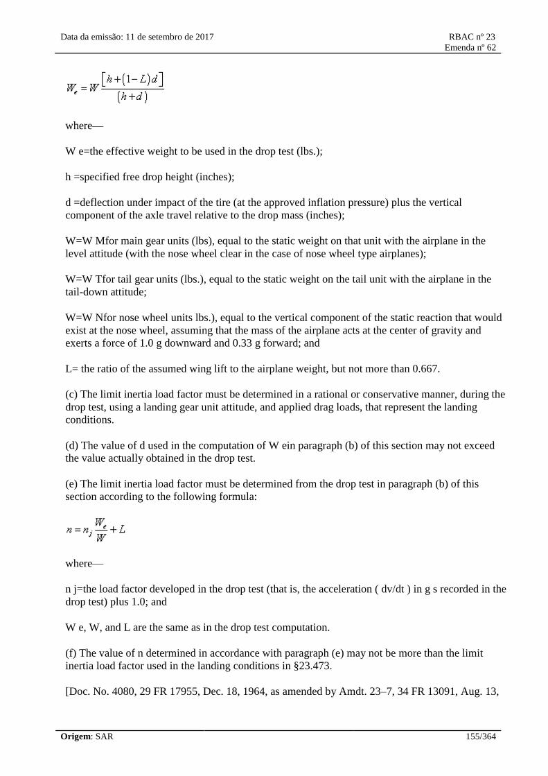
Data da emissão: 11 de setembro de 2017 RBAC nº 23
Emenda nº 62
Origem: SAR 155/364
where—
W e=the effective weight to be used in the drop test (lbs.);
h =specified free drop height (inches);
d =deflection under impact of the tire (at the approved inflation pressure) plus the vertical
component of the axle travel relative to the drop mass (inches);
W=W Mfor main gear units (lbs), equal to the static weight on that unit with the airplane in the
level attitude (with the nose wheel clear in the case of nose wheel type airplanes);
W=W Tfor tail gear units (lbs.), equal to the static weight on the tail unit with the airplane in the
tail-down attitude;
W=W Nfor nose wheel units lbs.), equal to the vertical component of the static reaction that would
exist at the nose wheel, assuming that the mass of the airplane acts at the center of gravity and
exerts a force of 1.0 g downward and 0.33 g forward; and
L= the ratio of the assumed wing lift to the airplane weight, but not more than 0.667.
(c) The limit inertia load factor must be determined in a rational or conservative manner, during the
drop test, using a landing gear unit attitude, and applied drag loads, that represent the landing
conditions.
(d) The value of d used in the computation of W ein paragraph (b) of this section may not exceed
the value actually obtained in the drop test.
(e) The limit inertia load factor must be determined from the drop test in paragraph (b) of this
section according to the following formula:
where—
n j=the load factor developed in the drop test (that is, the acceleration ( dv/dt ) in g s recorded in the
drop test) plus 1.0; and
W e, W, and L are the same as in the drop test computation.
(f) The value of n determined in accordance with paragraph (e) may not be more than the limit
inertia load factor used in the landing conditions in §23.473.
[Doc. No. 4080, 29 FR 17955, Dec. 18, 1964, as amended by Amdt. 23–7, 34 FR 13091, Aug. 13,

Data da emissão: 11 de setembro de 2017 RBAC nº 23
Emenda nº 62
Origem: SAR 156/364
1969; Amdt. 23–48, 61 FR 5148, Feb. 9, 1996]
§ 23.726 Ground load dynamic tests.
(a) If compliance with the ground load requirements of §§23.479 through 23.483 is shown
dynamically by drop test, one drop test must be conducted that meets §23.725 except that the drop
height must be—
(1) 2.25 times the drop height prescribed in §23.725(a); or
(2) Sufficient to develop 1.5 times the limit load factor.
(b) The critical landing condition for each of the design conditions specified in §§23.479 through
23.483 must be used for proof of strength.
[Amdt. 23–7, 34 FR 13091, Aug. 13, 1969]
§ 23.727 Reserve energy absorption drop test.
(a) If compliance with the reserve energy absorption requirement in §23.723(b) is shown by free
drop tests, the drop height may not be less than 1.44 times that specified in §23.725.
(b) If the effect of wing lift is provided for, the units must be dropped with an effective mass equal
to W e= Wh/(h+d), when the symbols and other details are the same as in §23.725.
[Doc. No. 4080, 29 FR 17955, Dec. 18, 1964, as amended by Amdt. 23–7, 34 FR 13091, Aug. 13,
1969]
§ 23.729 Landing gear extension and retraction system.
(a) General. For airplanes with retractable landing gear, the following apply:
(1) Each landing gear retracting mechanism and its supporting structure must be designed for
maximum flight load factors with the gear retracted and must be designed for the combination of
friction, inertia, brake torque, and air loads, occurring during retraction at any airspeed up to 1.6 V
S1with flaps retracted, and for any load factor up to those specified in §23.345 for the flaps-
extended condition.
(2) The landing gear and retracting mechanism, including the wheel well doors, must withstand
flight loads, including loads resulting from all yawing conditions specified in §23.351, with the
landing gear extended at any speed up to at least 1.6 V S1with the flaps retracted.
(b) Landing gear lock. There must be positive means (other than the use of hydraulic pressure) to
keep the landing gear extended.
(c) Emergency operation. For a landplane having retractable landing gear that cannot be extended
manually, there must be means to extend the landing gear in the event of either—
(1) Any reasonably probable failure in the normal landing gear operation system; or

Data da emissão: 11 de setembro de 2017 RBAC nº 23
Emenda nº 62
Origem: SAR 157/364
(2) Any reasonably probable failure in a power source that would prevent the operation of the
normal landing gear operation system.
(d) Operation test. The proper functioning of the retracting mechanism must be shown by operation
tests.
(e) Position indicator. If a retractable landing gear is used, there must be a landing gear position
indicator (as well as necessary switches to actuate the indicator) or other means to inform the pilot
that each gear is secured in the extended (or retracted) position. If switches are used, they must be
located and coupled to the landing gear mechanical system in a manner that prevents an erroneous
indication of either “down and locked” if each gear is not in the fully extended position, or “up and
locked” if each landing gear is not in the fully retracted position.
(f) Landing gear warning. For landplanes, the following aural or equally effective landing gear
warning devices must be provided:
(1) A device that functions continuously when one or more throttles are closed beyond the power
settings normally used for landing approach if the landing gear is not fully extended and locked. A
throttle stop may not be used in place of an aural device. If there is a manual shutoff for the warning
device prescribed in this paragraph, the warning system must be designed so that when the warning
has been suspended after one or more throttles are closed, subsequent retardation of any throttle to,
or beyond, the position for normal landing approach will activate the warning device.
(2) A device that functions continuously when the wing flaps are extended beyond the maximum
approach flap position, using a normal landing procedure, if the landing gear is not fully extended
and locked. There may not be a manual shutoff for this warning device. The flap position sensing
unit may be installed at any suitable location. The system for this device may use any part of the
system (including the aural warning device) for the device required in paragraph (f)(1) of this
section.
(g) Equipment located in the landing gear bay. If the landing gear bay is used as the location for
equipment other than the landing gear, that equipment must be designed and installed to minimize
damage from items such as a tire burst, or rocks, water, and slush that may enter the landing gear
bay.
[Doc. No. 4080, 29 FR 17955, Dec. 18, 1964, as amended by Amdt. 23–7, 34 FR 13091, Aug. 13,
1969; Amdt. 23–21, 43 FR 2318, Jan. 1978; Amdt. 23–26, 45 FR 60171, Sept. 11, 1980; Amdt. 23–
45, 58 FR 42164, Aug. 6, 1993; Amdt. 23–49, 61 FR 5166, Feb. 9, 1996]
§ 23.731 Wheels.
(a) The maximum static load rating of each wheel may not be less than the corresponding static
ground reaction with—
(1) Design maximum weight; and
(2) Critical center of gravity.
(b) The maximum limit load rating of each wheel must equal or exceed the maximum radial limit

Data da emissão: 11 de setembro de 2017 RBAC nº 23
Emenda nº 62
Origem: SAR 158/364
load determined under the applicable ground load requirements of this part.
[Doc. No. 4080, 29 FR 17955, Dec. 18, 1964, as amended by Amdt. 23–45, 58 FR 42165, Aug. 6,
1993]
§ 23.733 Tires.
(a) Each landing gear wheel must have a tire whose approved tire ratings (static and dynamic) are
not exceeded—
(1) By a load on each main wheel tire) to be compared to the static rating approved for such tires)
equal to the corresponding static ground reaction under the design maximum weight and critical
center of gravity; and
(2) By a load on nose wheel tires (to be compared with the dynamic rating approved for such tires)
equal to the reaction obtained at the nose wheel, assuming the mass of the airplane to be
concentrated at the most critical center of gravity and exerting a force of 1.0 W downward and 0.31
W forward (where W is the design maximum weight), with the reactions distributed to the nose and
main wheels by the principles of statics and with the drag reaction at the ground applied only at
wheels with brakes.
(b) If specially constructed tires are used, the wheels must be plainly and conspicuously marked to
that effect. The markings must include the make, size, number of plies, and identification marking
of the proper tire.
(c) Each tire installed on a retractable landing gear system must, at the maximum size of the tire
type expected in service, have a clearance to surrounding structure and systems that is adequate to
prevent contact between the tire and any part of the structure of systems.
[Doc. No. 4080, 29 FR 17955, Dec. 18, 1964, as amended by Amdt. 23–7, 34 FR 13092, Aug. 13,
1969; Amdt. 23–17, 41 FR 55464, Dec. 20, 1976; Amdt. 23–45, 58 FR 42165, Aug. 6, 1993]
23.735 Brakes.
(a) Brakes must be provided. The landing brake
kinetic energy capacity rating of each main
wheel brake assembly must not be less than the
kinetic energy absorption requirements
determined under either of the following
methods:
(1) The brake kinetic energy absorption
requirements must be based on a conservative
rational analysis of the sequence of events
expected during landing at the design landing
weight.
(2) Instead of a rational analysis, the kinetic
energy absorption requirements for each main
23.735 Freios.
(a) Freios devem ser providos. A estimativa da
capacidade de energia cinética de frenagem no
pouso de cada conjunto de freio não pode ser
menor do que os requisitos de absorção de
energia cinética determinados segundo um dos
seguintes métodos a seguir:
(1) Os requisitos de absorção de energia
cinética do freio devem ser baseados em uma
análise racional conservativa de uma sequência
de eventos esperados durante o pouso no peso
de pouso de projeto.
(2) Ao invés de uma análise racional, os
requisitos de absorção de energia cinética para

Data da emissão: 11 de setembro de 2017 RBAC nº 23
Emenda nº 62
Origem: SAR 159/364
wheel brake assembly may be derived from the
following formula:
KE=0.0443 WV2 /N
where:
KE=Kinetic energy per wheel (ft.-lb.);
W=Design landing weight (lb.);
V=Airplane speed in knots. V must be not less
than VS √, the poweroff stalling speed of the
airplane at sea level, at the design landing
weight, and in the landing configuration; and
N=Number of main wheels with brakes.
(b) Brakes must be able to prevent the wheels
from rolling on a paved runway with takeoff
power on the critical engine, but need not
prevent movement of the airplane with wheels
locked.
(c) During the landing distance determination
required by section 23.75 of this RBAC, the
pressure on the wheel braking system must not
exceed the pressure specified by the brake
manufacturer.
(d) If antiskid devices are installed, the devices
and associated systems must be designed so
that no single probable malfunction or failure
will result in a hazardous loss of braking ability
or directional control of the airplane.
(e) For airplanes required to meet section 23.55
of this RBAC, the rejected takeoff brake
kinetic energy capacity rating of each main
wheel brake assembly may not be less than the
kinetic energy absorption requirements
determined under either of the following
methods:
(1) The brake kinetic energy absorption
requirements must be based on a conservative
rational analysis of the sequence of events
expected during a rejected takeoff at the design
cada conjunto de freio principal podem ser
derivados da seguinte fórmula:
KE=0.0443 WV2 /N
Tal que:
KE=Energia cinética por roda(s) com freios
(ft.-lb.);
W= Massa de pouso de projeto (lb.);
V=Velocidade do avião em nós. V não pode ser
menor do que VS √, velocidade de estol sem
tração de potência do avião o nível do mar, no
peso de pouso de projeto e na configuração
para pouso; e
N=Número de rodas com freios principais.
(b) Os freios devem ser capazes de evitar que
as rodas rolem em uma pista pavimentada com
potência de decolagem no motor crítico, mas
não é necessário que evite o movimento do
avião com as rodas travadas.
(c) Durante a determinação da distância de
pouso requerida pela seção 23.75 deste RBAC,
a pressão no sistema de frenagem da roda não
pode exceder a pressão especificada pelo
fabricante do freio.
(d) Se dispositivos de anti-derrapagem são
instalados, os dispositivos e sistemas
associados devem ser projetados, tal que
nenhuma provável falha ou mau funcionamento
simples não resultará em uma perda de
consequências perigosas da capacidade de
frenagem ou controle direcional do avião.
(e) Para aviões requeridos a cumprir com a
seção 23.55 deste RBAC, a estimativa da
capacidade de energia cinética de frenagem em
uma decolagem abortada de cada conjunto
principal de freio não pode ser menor do que os
requisitos de absorção de energia cinética
determinados segundo um dos seguintes
métodos:
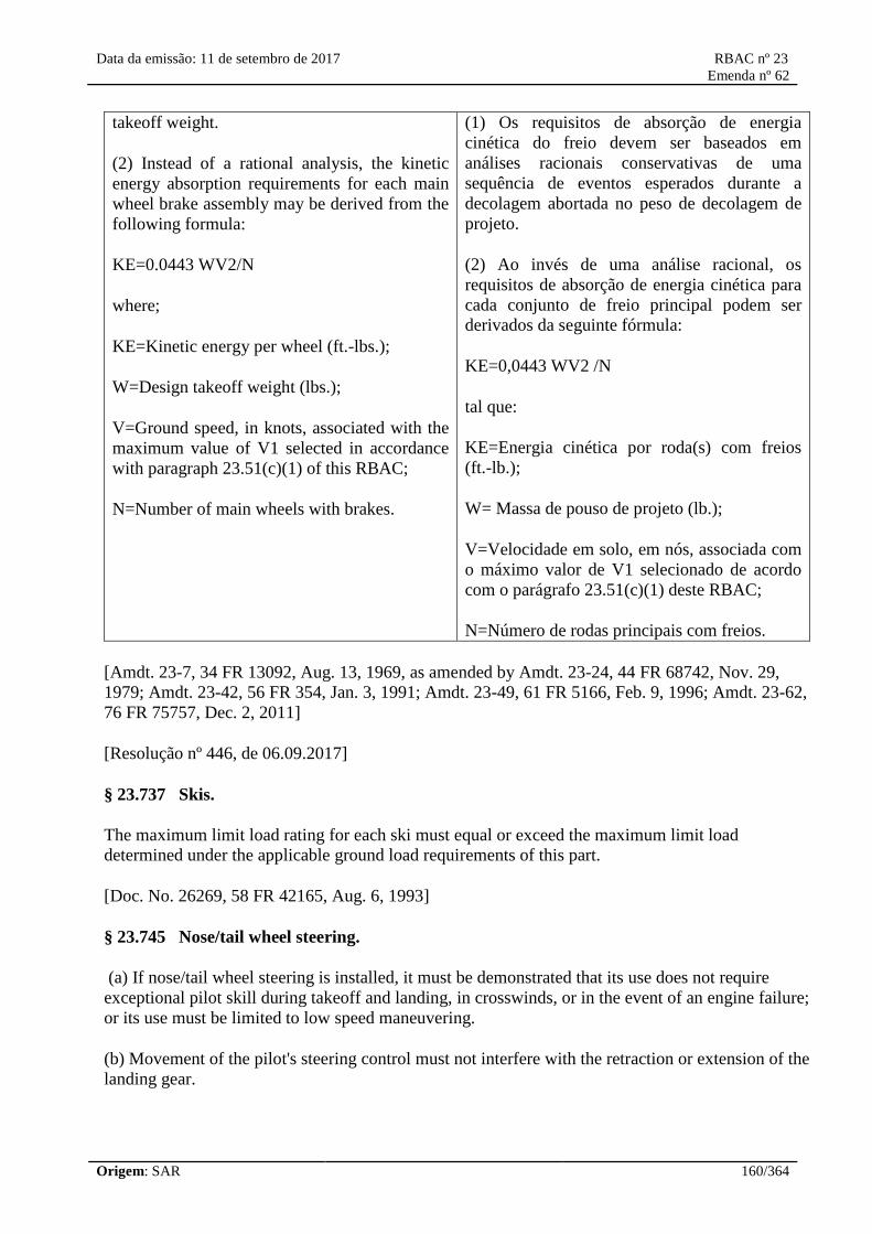
Data da emissão: 11 de setembro de 2017 RBAC nº 23
Emenda nº 62
Origem: SAR 160/364
takeoff weight.
(2) Instead of a rational analysis, the kinetic
energy absorption requirements for each main
wheel brake assembly may be derived from the
following formula:
KE=0.0443 WV2/N
where;
KE=Kinetic energy per wheel (ft.-lbs.);
W=Design takeoff weight (lbs.);
V=Ground speed, in knots, associated with the
maximum value of V1 selected in accordance
with paragraph 23.51(c)(1) of this RBAC;
N=Number of main wheels with brakes.
(1) Os requisitos de absorção de energia
cinética do freio devem ser baseados em
análises racionais conservativas de uma
sequência de eventos esperados durante a
decolagem abortada no peso de decolagem de
projeto.
(2) Ao invés de uma análise racional, os
requisitos de absorção de energia cinética para
cada conjunto de freio principal podem ser
derivados da seguinte fórmula:
KE=0,0443 WV2 /N
tal que:
KE=Energia cinética por roda(s) com freios
(ft.-lb.);
W= Massa de pouso de projeto (lb.);
V=Velocidade em solo, em nós, associada com
o máximo valor de V1 selecionado de acordo
com o parágrafo 23.51(c)(1) deste RBAC;
N=Número de rodas principais com freios.
[Amdt. 23-7, 34 FR 13092, Aug. 13, 1969, as amended by Amdt. 23-24, 44 FR 68742, Nov. 29,
1979; Amdt. 23-42, 56 FR 354, Jan. 3, 1991; Amdt. 23-49, 61 FR 5166, Feb. 9, 1996; Amdt. 23-62,
76 FR 75757, Dec. 2, 2011]
[Resolução nº 446, de 06.09.2017]
§ 23.737 Skis.
The maximum limit load rating for each ski must equal or exceed the maximum limit load
determined under the applicable ground load requirements of this part.
[Doc. No. 26269, 58 FR 42165, Aug. 6, 1993]
§ 23.745 Nose/tail wheel steering.
(a) If nose/tail wheel steering is installed, it must be demonstrated that its use does not require
exceptional pilot skill during takeoff and landing, in crosswinds, or in the event of an engine failure;
or its use must be limited to low speed maneuvering.
(b) Movement of the pilot's steering control must not interfere with the retraction or extension of the
landing gear.

Data da emissão: 11 de setembro de 2017 RBAC nº 23
Emenda nº 62
Origem: SAR 161/364
[Doc. No. 27806, 61 FR 5166, Feb. 9, 1996]
Floats and Hulls
§ 23.751 Main float buoyancy.
(a) Each main float must have—
(1) A buoyancy of 80 percent in excess of the buoyancy required by that float to support its portion
of the maximum weight of the seaplane or amphibian in fresh water; and
(2) Enough watertight compartments to provide reasonable assurance that the seaplane or
amphibian will stay afloat without capsizing if any two compartments of any main float are flooded.
(b) Each main float must contain at least four watertight compartments approximately equal in
volume.
[Doc. No. 4080, 29 FR 17955, Dec. 18, 1964, as amended by Amdt. 23–45, 58 FR 42165, Aug. 6,
1993]
§ 23.753 Main float design.
Each seaplane main float must meet the requirements of §23.521.
[Doc. No. 26269, 58 FR 42165, Aug. 6, 1993]
§ 23.755 Hulls.
(a) The hull of a hull seaplane or amphibian of 1,500 pounds or more maximum weight must have
watertight compartments designed and arranged so that the hull auxiliary floats, and tires (if used),
will keep the airplane afloat without capsizing in fresh water when—
(1) For airplanes of 5,000 pounds or more maximum weight, any two adjacent compartments are
flooded; and
(2) For airplanes of 1,500 pounds up to, but not including, 5,000 pounds maximum weight, any
single compartment is flooded.
(b) Watertight doors in bulkheads may be used for communication between compartments.
[Doc. No. 4080, 29 FR 17955, Dec. 18, 1964, as amended by Amdt. 23–45, 58 FR 42165, Aug. 6,
1993; Amdt. 23–48, 61 FR 5148, Feb. 9, 1996]
§ 23.757 Auxiliary floats.
Auxiliary floats must be arranged so that, when completely submerged in fresh water, they provide
a righting moment of at least 1.5 times the upsetting moment caused by the seaplane or amphibian
being tilted.
Data da emissão: 11 de setembro de 2017 RBAC nº 23
Emenda nº 62
Origem: SAR 162/364
Personnel and Cargo Accommodations
§ 23.771 Pilot compartment.
For each pilot compartment—
(a) The compartment and its equipment must allow each pilot to perform his duties without
unreasonable concentration or fatigue;
(b) Where the flight crew are separated from the passengers by a partition, an opening or openable
window or door must be provided to facilitate communication between flight crew and the
passengers; and
(c) The aerodynamic controls listed in §23.779, excluding cables and control rods, must be located
with respect to the propellers so that no part of the pilot or the controls lies in the region between
the plane of rotation of any inboard propeller and the surface generated by a line passing through
the center of the propeller hub making an angle of 5 degrees forward or aft of the plane of rotation
of the propeller.
[Doc. No. 4080, 29 FR 17955, Dec. 18, 1964, as amended by Amdt. 23–14, 38 FR 31821, Nov. 19,
1973]
§ 23.773 Pilot compartment view.
(a) Each pilot compartment must be—
(1) Arranged with sufficiently extensive, clear and undistorted view to enable the pilot to safely
taxi, takeoff, approach, land, and perform any maneuvers within the operating limitations of the
airplane.
(2) Free from glare and reflections that could interfere with the pilot's vision. Compliance must be
shown in all operations for which certification is requested; and
(3) Designed so that each pilot is protected from the elements so that moderate rain conditions do
not unduly impair the pilot's view of the flight path in normal flight and while landing.
(b) Each pilot compartment must have a means to either remove or prevent the formation of fog or
frost on an area of the internal portion of the windshield and side windows sufficiently large to
provide the view specified in paragraph (a)(1) of this section. Compliance must be shown under all
expected external and internal ambient operating conditions, unless it can be shown that the
windshield and side windows can be easily cleared by the pilot without interruption of normal pilot
duties.
[Doc. No. 26269, 58 FR 42165, Aug. 6, 1993; 71 FR 537, Jan. 5, 2006]
§ 23.775 Windshields and windows.
(a) The internal panels of windshields and windows must be constructed of a nonsplintering
material, such as nonsplintering safety glass.

Data da emissão: 11 de setembro de 2017 RBAC nº 23
Emenda nº 62
Origem: SAR 163/364
(b) The design of windshields, windows, and canopies in pressurized airplanes must be based on
factors peculiar to high altitude operation, including—
(1) The effects of continuous and cyclic pressurization loadings;
(2) The inherent characteristics of the material used; and
(3) The effects of temperatures and temperature gradients.
(c) On pressurized airplanes, if certification for operation up to and including 25,000 feet is
requested, an enclosure canopy including a representative part of the installation must be subjected
to special tests to account for the combined effects of continuous and cyclic pressurization loadings
and flight loads, or compliance with the fail-safe requirements of paragraph (d) of this section must
be shown.
(d) If certification for operation above 25,000 feet is requested the windshields, window panels, and
canopies must be strong enough to withstand the maximum cabin pressure differential loads
combined with critical aerodynamic pressure and temperature effects, after failure of any load-
carrying element of the windshield, window panel, or canopy.
(e) The windshield and side windows forward of the pilot's back when the pilot is seated in the
normal flight position must have a luminous transmittance value of not less than 70 percent.
(f) Unless operation in known or forecast icing conditions is prohibited by operating limitations, a
means must be provided to prevent or to clear accumulations of ice from the windshield so that the
pilot has adequate view for taxi, takeoff, approach, landing, and to perform any maneuvers within
the operating limitations of the airplane.
(g) In the event of any probable single failure, a transparency heating system must be incapable of
raising the temperature of any windshield or window to a point where there would be—
(1) Structural failure that adversely affects the integrity of the cabin; or
(2) There would be a danger of fire.
(h) In addition, for commuter category airplanes, the following applies:
(1) Windshield panes directly in front of the pilots in the normal conduct of their duties, and the
supporting structures for these panes, must withstand, without penetration, the impact of a two-
pound bird when the velocity of the airplane (relative to the bird along the airplane's flight path) is
equal to the airplane's maximum approach flap speed.
(2) The windshield panels in front of the pilots must be arranged so that, assuming the loss of vision
through any one panel, one or more panels remain available for use by a pilot seated at a pilot
station to permit continued safe flight and landing.
[Doc. No. 4080, 29 FR 17955, Dec. 18, 1964, as amended by Amdt. 23–7, 34 FR 13092, Aug. 13,
1969; Amdt. 23–45, 58 FR 42165, Aug. 6, 1993; 58 FR 51970, Oct. 5, 1993; Amdt. 23–49, 61 FR
5166, Feb. 9, 1996]

Data da emissão: 11 de setembro de 2017 RBAC nº 23
Emenda nº 62
Origem: SAR 164/364
23.777 Cockpit controls.
(a) Each cockpit control must be located and
(except where its function is obvious)
identified to provide convenient operation and
to prevent confusion and inadvertent operation.
(b) The controls must be located and arranged
so that the pilot, when seated, has full and
unrestricted movement of each control without
interference from either his clothing or the
cockpit structure.
(c) Powerplant controls must be located:
(1) For multiengine airplanes, on the pedestal
or overhead at or near the center of the cockpit;
(2) For single and tandem seated single-engine
airplanes, on the left side console or instrument
panel;
(3) For other single-engine airplanes at or near
the center of the cockpit, on the pedestal,
instrument panel, or overhead; and
(4) For airplanes, with side-by-side pilot seats
and with two sets of powerplant controls, on
left and right consoles.
(d) When separate and distinct control levers
are co-located (such as located together on the
pedestal), the control location order from left to
right must be power (thrust) lever, propeller
(rpm control), and mixture control (condition
lever and fuel cut-off for turbine-powered
airplanes). Power (thrust) levers must be easily
distinguishable from other controls, and
provide for accurate, consistent operation.
Carburetor heat or alternate air control must be
to the left of the throttle or at least eight inches
(203,2 mm) from the mixture control when
located other than on a pedestal. Carburetor
heat or alternate air control, when located on a
pedestal, must be aft or below the power
(thrust) lever. Supercharger controls must be
located below or aft of the propeller controls.
Airplanes with tandem seating or single-place
airplanes may utilize control locations on the
23.777 Controles de cabine de comando.
(a) Cada controle da cabine de comando deve
estar localizado e (exceto quando sua função é
óbvia) identificado para prover operação
conveniente e evitar confusão e operação
inadvertida.
(b) Os controles devem estar localizados e
organizados de modo que o piloto, quando
sentado, tenha acesso completo e irrestrito de
cada controle sem interferência de sua
vestimenta ou da estrutura da cabine de
comando.
(c) Os controles do grupo motopropulsor
devem estar localizados:
(1) Para aviões multimotores, no pedestal ou no
painel superior no centro ou próximo ao centro
da cabine de comando;
(2) Para aviões monomotores monoposto ou
com assentos em “tandem”, no console
esquerdo ou painel de instrumentos;
(3) Para os outros aviões monomotores no
centro ou próximo ao centro da cabine de
comando, no pedestal, no painel de
instrumento, ou no painel superior; e
(4) Para aviões, com assentos de piloto lado a
lado e com dois conjuntos de controle do grupo
motopropulsor, nos consoles esquerdo e direito.
(d) Quando alavancas de controle separadas e
distintas estão co-localizadas (como no caso de
estar localizadas juntas no pedestal), a ordem
de localização dos controles da esquerda para a
direita deve ser manete de potência (tração),
hélice (controle de RPM), e controle de mistura
(manete de condição e corte de combustível
para aviões turbo hélices). Os manetes de
potência (tração) devem ser facilmente
distinguíveis dos outros controles, e prover
operação acurada e consistente. O controle do
aquecimento do carburador ou controle da
entrada alternativa de ar deve estar a esquerda
do manete de potência ou pelo menos oito

Data da emissão: 11 de setembro de 2017 RBAC nº 23
Emenda nº 62
Origem: SAR 165/364
left side of the cabin compartment; however,
location order from left to right must be power
(thrust) lever, propeller (rpm control), and
mixture control.
(e) Identical powerplant controls for each
engine must be located to prevent confusion as
to the engines they control.
(1) Conventional multiengine powerplant
controls must be located so that the left
control(s) operates the left engines(s) and the
right control(s) operates the right engine(s).
(2) On twin-engine airplanes with front and
rear engine locations (tandem), the left
powerplant controls must operate the front
engine and the right powerplant controls must
operate the rear engine.
(f) Wing flap and auxiliary lift device controls
must be located:
(1) Centrally, or to the right of the pedestal or
powerplant throttle control centerline; and
(2) Far enough away from the landing gear
control to avoid confusion.
(g) The landing gear control must be located to
the left of the throttle centerline or pedestal
centerline.
(h) Each fuel feed selector control must comply
with section 23.995 and be located and
arranged so that the pilot can see and reach it
without moving any seat or primary flight
control when his seat is at any position in
which it can be placed.
(1) For a mechanical fuel selector:
(i) The indication of the selected fuel valve
position must be by means of a pointer and
must provide positive identification and feel
(detent, etc.) of the selected position.
(ii) The position indicator pointer must be
located at the part of the handle that is the
polegadas (203,2 mm) do manete de mistura
quando localizado fora do pedestal. O controle
do aquecimento do carburador ou controle da
entrada alternativa de ar, quando localizado
num pedestal deve estar atrás ou abaixo dos
manetes de potência (tração). Os controles do
superalimentador devem estar localizados
abaixo ou atrás dos controles de hélice. Os
aviões com assentos em “tandem” ou aviões
monopostos podem utilizar as posições dos
controles no lado esquerdo do compartimento
da cabine; entretanto, a ordem de
posicionamento da esquerda para a direita deve
ser manete de potência (tração), hélice
(controle de RPM) e controle de mistura.
(e) Os controles do grupo motopropulsor
idênticos para cada motor devem estar
localizados de modo a evitar confusão sobre
qual motor controlam.
(1) Os controles do grupo motopropulsor
multimotores convencionais devem estar
localizados de modo que o(s) controle(s) da
esquerda opere(m) o(s) motor(es) da esquerda e
o(s) controle(s) da direita opere(m) o(s)
motor(es) da direita.
(2) Os aviões bimotores com motores
localizados à frente e atrás (tandem), os
controles do grupo motopropulsor esquerdo
devem operar o motor dianteiro e os controles
do grupo motopropulsor direito devem operar o
motor traseiro.
(f) Os controles de flap da asa e dispositivo
auxiliar de sustentação devem estar
localizados:
(1) No centro, ou à direita do pedestal ou do
eixo central do manete de potência; e
(2) Suficientemente afastados da alavanca de
trem de pouso para evitar confusão.
(g) A alavanca de trem de pouso deve estar
localizada à esquerda do eixo central do manete
de potência ou eixo central do pedestal.

Data da emissão: 11 de setembro de 2017 RBAC nº 23
Emenda nº 62
Origem: SAR 166/364
maximum dimension of the handle measured
from the center of rotation.
(2) For electrical or electronic fuel selector:
(i) Digital controls or electrical switches must
be properly labelled.
(ii) Means must be provided to indicate to the
flight crew the tank or function selected.
Selector switch position is not acceptable as a
means of indication. The “off” or “closed”
position must be indicated in red.
(3) If the fuel valve selector handle or electrical
or digital selection is also a fuel shut-off
selector, the off position marking must be
colored red. If a separate emergency shut-off
means is provided, it also must be colored red.
(h) Cada chave seletora de combustível deve
cumprir com a seção 23.995 e estar
posicionada e organizada de modo que o piloto
possa ver e alcançar sem movimentar qualquer
assento ou controle de voo primário quando seu
assento está em qualquer posição que possa ser
colocado.
(1) Para uma seletora de combustível
mecânica:
(i) A indicação da posição da válvula seletora
de combustível deve ser feita por meio de um
indicador e deve prover identificação positiva e
tátil (batente, etc.) da posição selecionada.
(ii) O indicador de posição deve estar
localizado na parte do punho com a máxima
dimensão medida a partir do centro de rotação
do punho.
(2) Para uma seletora de combustível elétrica
ou eletrônica:
(i) Controles digitais ou chaves elétricas devem
estar devidamente identificados.
(ii) Devem ser providos meios para indicar à
tripulação de voo o tanque ou a função
selecionada. A posição da chave seletora não é
aceitável como um meio de indicação. A
posição “desligada” (“off”) ou “fechada”
(“closed”) deve estar indicada em vermelho.
(3) Se a seletora manual ou elétrica ou digital
da válvula de combustível é também uma
seletora de corte de combustível, a marca da
posição desligada deve estar em vermelho. Se
um meio de corte de emergência separado
existir, ele também deve estar em vermelho.
Doc. No. 4080, 29 FR 17955, Dec. 18, 1964, as amended by Amdt. 23-7, 34 FR 13092, Aug. 13,
1969; Amdt. 23-33, 51 FR 26656, July 24, 1986; Amdt. 23-51, 61 FR 5136, Feb. 9, 1996; Amdt.
23-62, 76 FR 75757, Dec. 2, 2011]
[Resolução nº 446, de 06.09.2017]
§ 23.779 Motion and effect of cockpit controls.

Data da emissão: 11 de setembro de 2017 RBAC nº 23
Emenda nº 62
Origem: SAR 167/364
Cockpit controls must be designed so that they operate in accordance with the following movement
and actuation:
(a) Aerodynamic controls:
Motion and effect
(1) Primary controls:
Aileron Right (clockwise) for right wing down.
Elevator Rearward for nose up.
Rudder Right pedal forward for nose right.
(2) Secondary controls:
Flaps (or
auxiliary lift
devices)
Forward or up for flaps up or auxiliary device stowed; rearward or down
for flaps down or auxiliary device deployed.
Trim tabs (or
equivalent)
Switch motion or mechanical rotation of control to produce similar
rotation of the airplane about an axis parallel to the axis control. Axis of
roll trim control may be displaced to accommodate comfortable actuation
by the pilot. For single-engine airplanes, direction of pilot's hand
movement must be in the same sense as airplane response for rudder trim
if only a portion of a rotational element is accessible.
(b) Powerplant and auxiliary controls:
Motion and effect
(1) Powerplant controls:
Power (thrust) lever Forward to increase forward thrust and rearward to
increase rearward thrust.
Propellers Forward to increase rpm.
Mixture Forward or upward for rich.
Fuel Forward for open.
Carburetor, air heat or
alternate air
Forward or upward for cold.
Supercharger Forward or upward for low blower.
Turbosuper-chargers Forward, upward, or clockwise to increase pressure.
Rotary controls Clockwise from off to full on.
(2) Auxiliary controls:
Fuel tank selector Right for right tanks, left for left tanks.

Data da emissão: 11 de setembro de 2017 RBAC nº 23
Emenda nº 62
Origem: SAR 168/364
Landing gear Down to extend.
Speed brakes Aft to extend.
[Amdt. 23–33, 51 FR 26656, July 24, 1986, as amended by Amdt. 23–51, 61 FR 5136, Feb. 9,
1996]
§ 23.781 Cockpit control knob shape.
(a) Flap and landing gear control knobs must conform to the general shapes (but not necessarily the
exact sizes or specific proportions) in the following figure:

Data da emissão: 11 de setembro de 2017 RBAC nº 23
Emenda nº 62
Origem: SAR 169/364
(b) Powerplant control knobs must conform to the general shapes (but not necessarily the exact
sizes or specific proportions) in the following figure:
[Doc. No. 4080, 29 FR 17955, Dec. 18, 1964; 30 FR 258, Jan. 9, 1965, as amended by Amdt. 23–
33, 51 FR 26657, July 24, 1986]
§ 23.783 Doors.
(a) Each closed cabin with passenger accommodations must have at least one adequate and easily
accessible external door.
(b) Passenger doors must not be located with respect to any propeller disk or any other potential
hazard so as to endanger persons using the door.
(c) Each external passenger or crew door must comply with the following requirements:
(1) There must be a means to lock and safeguard the door against inadvertent opening during flight
by persons, by cargo, or as a result of mechanical failure.
(2) The door must be openable from the inside and the outside when the internal locking
mechanism is in the locked position.
(3) There must be a means of opening which is simple and obvious and is arranged and marked
inside and outside so that the door can be readily located, unlocked, and opened, even in darkness.
(4) The door must meet the marking requirements of §23.811 of this part.
(5) The door must be reasonably free from jamming as a result of fuselage deformation in an
emergency landing.
(6) Auxiliary locking devices that are actuated externally to the airplane may be used but such
devices must be overridden by the normal internal opening means.
(d) In addition, each external passenger or crew door, for a commuter category airplane, must
comply with the following requirements:
(1) Each door must be openable from both the inside and outside, even though persons may be
crowded against the door on the inside of the airplane.
(2) If inward opening doors are used, there must be a means to prevent occupants from crowding
against the door to the extent that would interfere with opening the door.
(3) Auxiliary locking devices may be used.
(e) Each external door on a commuter category airplane, each external door forward of any engine
or propeller on a normal, utility, or acrobatic category airplane, and each door of the pressure vessel
on a pressurized airplane must comply with the following requirements:
(1) There must be a means to lock and safeguard each external door, including cargo and service

Data da emissão: 11 de setembro de 2017 RBAC nº 23
Emenda nº 62
Origem: SAR 170/364
type doors, against inadvertent opening in flight, by persons, by cargo, or as a result of mechanical
failure or failure of a single structural element, either during or after closure.
(2) There must be a provision for direct visual inspection of the locking mechanism to determine if
the external door, for which the initial opening movement is not inward, is fully closed and locked.
The provisions must be discernible, under operating lighting conditions, by a crewmember using a
flashlight or an equivalent lighting source.
(3) There must be a visual warning means to signal a flight crewmember if the external door is not
fully closed and locked. The means must be designed so that any failure, or combination of failures,
that would result in an erroneous closed and locked indication is improbable for doors for which the
initial opening movement is not inward.
(f) In addition, for commuter category airplanes, the following requirements apply:
(1) Each passenger entry door must qualify as a floor level emergency exit. This exit must have a
rectangular opening of not less than 24 inches wide by 48 inches high, with corner radii not greater
than one-third the width of the exit.
(2) If an integral stair is installed at a passenger entry door, the stair must be designed so that, when
subjected to the inertia loads resulting from the ultimate static load factors in §23.561(b)(2) and
following the collapse of one or more legs of the landing gear, it will not reduce the effectiveness of
emergency egress through the passenger entry door.
(g) If lavatory doors are installed, they must be designed to preclude an occupant from becoming
trapped inside the lavatory. If a locking mechanism is installed, it must be capable of being
unlocked from outside of the lavatory.
[Doc. No. 4080, 29 FR 17955, Dec. 18, 1964; 30 FR 258, Jan. 9, 1965, as amended by Amdt. 23–
36, 53 FR 30813, Aug. 15, 1988; Amdt. 23–46, 59 FR 25772, May 17, 1994; Amdt. 23–49, 61 FR
5166, Feb. 9, 1996]
23.785 Seats, berths, litters, safety belts,
and shoulder harnesses.
There must be a seat or berth for each occupant
that meets the following:
(a) Each seat/restraint system and the
supporting structure must be designed to
support occupants weighing at least 215
pounds (98 kg) when subjected to the
maximum load factors corresponding to the
specified flight and ground load conditions, as
defined in the approved operating envelope of
the airplane. In addition, these loads must be
multiplied by a factor of 1.33 in determining
23.785 Assentos, leitos, macas, cintos de
segurança, e cintos de ombro.
Deve haver um assento ou leito para cada
ocupante que satisfaça o seguinte:
(a) Cada assento/sistema de retenção e a
estrutura de apoio devem ser projetados para
suportar ocupantes pesando pelo menos 215
libras (98 kg) quando submetidos aos fatores de
carga máximos correspondentes às condições
específicas de carga no solo e voo, conforme
definido no envelope operacional aprovado do
avião. Em adição, essas cargas devem ser
multiplicadas por um fator de 1,33 na

Data da emissão: 11 de setembro de 2017 RBAC nº 23
Emenda nº 62
Origem: SAR 171/364
the strength of all fittings and the attachment
of:
(1) Each seat to the structure; and
(2) Each safety belt and shoulder harness to the
seat or structure.
(b) Each forward-facing or aft-facing
seat/restraint system in normal, utility, or
acrobatic category airplanes must consist of a
seat, a safety belt, and a shoulder harness, with
a metal-to-metal latching device, that are
designed to provide the occupant protection
provisions required in section 23.562. Other
seat orientations must provide the same level of
occupant protection as a forward-facing or aft-
facing seat with a safety belt and a shoulder
harness, and must provide the protection
provisions of section 23.562.
(c) For commuter category airplanes, each seat
and the supporting structure must be designed
for occupants weighing at least 170 pounds (77
kg) when subjected to the inertia loads
resulting from the ultimate static load factors
prescribed in paragraph 23.561(b)(2) of this
RBAC. Each occupant must be protected from
serious head injury when subjected to the
inertia loads resulting from these load factors
by a safety belt and shoulder harness, with a
metal-to-metal latching device, for the front
seats and a safety belt, or a safety belt and
shoulder harness, with a metal-to-metal
latching device, for each seat other than the
front seats. Commuter category jet airplanes,
must also comply with the requirements of
section 23.562.
(d) Each restraint system must have a single-
point release for occupant evacuation.
(e) The restraint system for each crewmember
must allow the crewmember, when seated with
the safety belt and shoulder harness fastened, to
perform all functions necessary for flight
operations.
(f) Each pilot seat must be designed for the
determinação da resistência de todos as
montagens e fixações de:
(1) Cada assento à estrutura; e
(2) Cada cinto de segurança e cinto de ombro
ao assento ou à estrutura.
(b) Cada assento/sistema de retenção orientado
para frente ou para trás em aviões de categoria
normal, utilidade, ou acrobática deve compor-
se de um assento, um cinto de segurança, e um
cinto de ombro, com um dispositivo de
trancamento metal-a-metal, que são projetados
para fornecer as provisões de proteção de
ocupante requeridas no 23.562. Outras
orientações de assento devem fornecer o
mesmo nível de proteção de ocupante que um
assento orientado para frente ou para trás com
um cinto de segurança e um cinto de ombro, e
devem fornecer as provisões de proteção do
23.562.
(c) Para aviões de categoria transporte regional,
cada assento e a estrutura de apoio devem ser
projetados para ocupantes pesando pelo menos
170 libras (77 kg) quando submetido às cargas
de inércia resultantes dos fatores de carga
estáticos finais prescritos em 23.561(b)(2)
deste RBAC. Cada ocupante deve ser protegido
de lesões graves na cabeça quando submetido
às cargas de inércia resultantes desses fatores
de carga, por meio de um cinto de segurança e
cinto de ombro, com um dispositivo de
trancamento metal-a-metal para os assentos
dianteiros e um cinto de segurança, ou um cinto
de segurança e cinto de ombro, com um
dispositivo de trancamento metal-a-metal, para
os demais assentos. Aviões a jato da categoria
transporte regional também devem cumprir
com os requisitos da seção 23.562.
(d) Cada sistema de retenção deve ter um ponto
único de liberação para a evacuação do
ocupante.
(e) O sistema de retenção para cada tripulante
deve permitir ao tripulante, enquanto sentado
com o cinto de segurança e cinto de ombro

Data da emissão: 11 de setembro de 2017 RBAC nº 23
Emenda nº 62
Origem: SAR 172/364
reactions resulting from the application of pilot
forces to the primary flight controls as
prescribed in section 23.395 of this RBAC.
(g) There must be a means to secure each
safety belt and shoulder harness, when not in
use, to prevent interference with the operation
of the airplane and with rapid occupant egress
in an emergency.
(h) Unless otherwise placarded, each seat in a
utility or acrobatic category airplane must be
designed to accommodate an occupant wearing
a parachute.
(i) The cabin area surrounding each seat,
including the structure, interior walls,
instrument panel, control wheel, pedals, and
seats within striking distance of the occupant's
head or torso (with the restraint system
fastened) must be free of potentially injurious
objects, sharp edges, protuberances, and hard
surfaces. If energy absorbing designs or
devices are used to meet this requirement, they
must protect the occupant from serious injury
when the occupant is subjected to the inertia
loads resulting from the ultimate static load
factors prescribed in paragraph 23.561(b)(2) of
this RBAC, or they must comply with the
occupant protection provisions of section
23.562 of this RBAC, as required in paragraphs
(b) and (c) of this section.
(j) Each seat track must be fitted with stops to
prevent the seat from sliding off the track.
(k) Each seat/restraint system may use design
features, such as crushing or separation of
certain components, to reduce occupant loads
when showing compliance with the
requirements of section 23.562 of this RBAC;
otherwise, the system must remain intact.
(l) For the purposes of this section, a front seat
is a seat located at a flight crewmember station
or any seat located alongside such a seat.
(m) Each berth, or provisions for a litter,
installed parallel to the longitudinal axis of the
afivelados, executar todas as funções
necessárias para as operações de voo.
(f) Cada assento de piloto deve ser projetado
para as reações resultantes da aplicação de
forças do piloto aos controles de voo primários
como prescrito no 23.395 deste RBAC.
(g) Deve haver um meio de reter cada cinto de
segurança e cinto de ombro, quando não em
uso, para evitar a interferência com a operação
do avião e com o rápido egresso do ocupante
em uma emergência.
(h) Salvo sinalizado de outra forma, cada
assento em um avião categoria utilidade ou
acrobática deve ser projetado para acomodar
um ocupante usando um pára-quedas.
(i) A área da cabine em torno de cada assento,
incluindo a estrutura, paredes internas, painel
de instrumentos, manche, pedais, e os assentos
dentro da trajetória de impacto da cabeça ou do
tronco do ocupante (com o sistema de retenção
afivelado) deve ser livre de objetos
potencialmente prejudiciais, arestas cortantes,
protuberâncias e superfícies duras. Se forem
usados projetos ou dispositivos de absorção de
energia para atender a essa exigência, eles
devem proteger os ocupantes de lesões graves
quando o ocupante é submetido às cargas de
inércia resultantes dos fatores de carga
estáticos finais prescrito no 23.561 (b) (2) deste
RBAC, ou eles devem cumprir com as
provisões de proteção de ocupante do 23.562
deste RBAC, conforme requerido nos
parágrafos (b) e (c) desta seção.
(j) Cada trilho de assento deve estar equipado
com batentes para impedir que o assento
deslize para fora do trilho.
(k) Cada assento/sistema de retenção pode usar
recursos de projeto, tais como o esmagamento
ou a separação de determinados componentes,
para reduzir as cargas no ocupante quando na
demonstração de cumprimento com os
requisitos do 23.562 deste RBAC; caso

Data da emissão: 11 de setembro de 2017 RBAC nº 23
Emenda nº 62
Origem: SAR 173/364
airplane, must be designed so that the forward
part has a padded end-board, canvas
diaphragm, or equivalent means that can
withstand the load reactions from a 215-pound
(98 kg) occupant when subjected to the inertia
loads resulting from the ultimate static load
factors of paragraph 23.561(b)(2) of this
RBAC. In addition:
(1) Each berth or litter must have an occupant
restraint system and may not have corners or
other parts likely to cause serious injury to a
person occupying it during emergency landing
conditions; and
(2) Occupant restraint system attachments for
the berth or litter must withstand the inertia
loads resulting from the ultimate static load
factors of paragraph 23.561(b)(2) of this
RBAC.
(n) Proof of compliance with the static strength
requirements of this section for seats and berths
approved as part of the type design and for seat
and berth installations may be shown by:
(1) Structural analysis, if the structure
conforms to conventional airplane types for
which existing methods of analysis are known
to be reliable;
(2) A combination of structural analysis and
static load tests to limit load; or
(3) Static load tests to ultimate loads.
contrário, o sistema deve permanecer intacto.
(l) Para os objetivos desta seção, um assento
dianteiro é um assento localizado em um posto
de um tripulante de voo ou qualquer assento
localizado ao lado de tal assento.
(m) Cada leito, ou provisões para uma maca,
instalados paralelamente ao eixo longitudinal
do avião, devem ser projetados de modo que a
parte da frente tenha um anteparo acolchoado,
diafragma de lona, ou outro meio equivalente
que possa suportar as reações de carga de um
ocupante de 215 libras (98 kg), quando
submetido às cargas de inércia resultante dos
fatores de carga estática finais do 23.561 (b)(2)
deste RBAC. Em adição:
(1) Cada leito ou maca deve ter um sistema de
retenção de ocupante e não pode ter cantos ou
outras partes que possam causar lesões graves à
pessoa que o ocupa, durante as condições de
pouso de emergência; e
(2) As fixações do sistema de retenção do
ocupante para o leito ou maca devem suportar
as cargas de inércia resultantes dos fatores de
carga estática final do 23.561 (b)(2) deste
RBAC.
(n) O cumprimento com os requisitos de
resistência estática desta seção para assentos e
leitos aprovados como parte do projeto de tipo
e para a instalação dos assentos e leitos pode
ser demonstrado por;
(1) Análise estrutural, se a estrutura está em
conformidade com os tipos convencionais de
avião para os quais os métodos existentes de
análise são reconhecidamente confiáveis;
(2) Uma combinação de análise estrutural e
ensaios de carga estática até a carga limite, ou
(3) Ensaio de carga estática até a carga final.
[Amdt. 23–36, 53 FR 30813, Aug. 15, 1988; Amdt. 23–36, 54 FR 50737, Dec. 11, 1989; Amdt. 23–
49, 61 FR 5167, Feb. 9, 1996]
Data da emissão: 11 de setembro de 2017 RBAC nº 23
Emenda nº 62
Origem: SAR 174/364
[Resolução nº 446, de 06.09.2017]
§ 23.787 Baggage and cargo compartments.
(a) Each baggage and cargo compartment must:
(1) Be designed for its placarded maximum weight of contents and for the critical load distributions
at the appropriate maximum load factors corresponding to the flight and ground load conditions of
this part.
(2) Have means to prevent the contents of any compartment from becoming a hazard by shifting,
and to protect any controls, wiring, lines, equipment or accessories whose damage or failure would
affect safe operations.
(3) Have a means to protect occupants from injury by the contents of any compartment, located aft
of the occupants and separated by structure, when the ultimate forward inertial load factor is 9g and
assuming the maximum allowed baggage or cargo weight for the compartment.
(b) Designs that provide for baggage or cargo to be carried in the same compartment as passengers
must have a means to protect the occupants from injury when the baggage or cargo is subjected to
the inertial loads resulting from the ultimate static load factors of §23.561(b)(3), assuming the
maximum allowed baggage or cargo weight for the compartment.
(c) For airplanes that are used only for the carriage of cargo, the flightcrew emergency exits must
meet the requirements of §23.807 under any cargo loading conditions.
[Doc. No. 27806, 61 FR 5167, Feb. 9, 1996]
§ 23.791 Passenger information signs.
For those airplanes in which the flightcrew members cannot observe the other occupants' seats or
where the flightcrew members' compartment is separated from the passenger compartment, there
must be at least one illuminated sign (using either letters or symbols) notifying all passengers when
seat belts should be fastened. Signs that notify when seat belts should be fastened must:
(a) When illuminated, be legible to each person seated in the passenger compartment under all
probable lighting conditions; and
(b) Be installed so that a flightcrew member can, when seated at the flightcrew member's station,
turn the illumination on and off.
[Doc. No. 27806, 61 FR 5167, Feb. 9, 1996]
§ 23.803 Emergency evacuation.
(a) For commuter category airplanes, an evacuation demonstration must be conducted utilizing the
maximum number of occupants for which certification is desired. The demonstration must be
conducted under simulated night conditions using only the emergency exits on the most critical side
of the airplane. The participants must be representative of average airline passengers with no prior

Data da emissão: 11 de setembro de 2017 RBAC nº 23
Emenda nº 62
Origem: SAR 175/364
practice or rehearsal for the demonstration. Evacuation must be completed within 90 seconds.
(b) In addition, when certification to the emergency exit provisions of §23.807(d)(4) is requested,
only the emergency lighting system required by §23.812 may be used to provide cabin interior
illumination during the evacuation demonstration required in paragraph (a) of this section.
[Amdt. 23–34, 52 FR 1831, Jan. 15, 1987, as amended by Amdt. 23–46, 59 FR 25773, May 17,
1994]
§ 23.805 Flightcrew emergency exits.
For airplanes where the proximity of the passenger emergency exits to the flightcrew area does not
offer a convenient and readily accessible means of evacuation for the flightcrew, the following
apply:
(a) There must be either one emergency exit on each side of the airplane, or a top hatch emergency
exit, in the flightcrew area;
(b) Each emergency exit must be located to allow rapid evacuation of the crew and have a size and
shape of at least a 19- by 20-inch unobstructed rectangular opening; and
(c) For each emergency exit that is not less than six feet from the ground, an assisting means must
be provided. The assisting means may be a rope or any other means demonstrated to be suitable for
the purpose. If the assisting means is a rope, or an approved device equivalent to a rope, it must
be—
(1) Attached to the fuselage structure at or above the top of the emergency exit opening or, for a
device at a pilot's emergency exit window, at another approved location if the stowed device, or its
attachment, would reduce the pilot's view; and
(2) Able (with its attachment) to withstand a 400-pound static load.
[Doc. No. 26324, 59 FR 25773, May 17, 1994]
23.807 Emergency exits.
(a) Number and location. Emergency exits
must be located to allow escape without
crowding in any probable crash attitude. The
airplane must have at least the following
emergency exits:
(1) For all airplanes with a seating capacity of
two or more, excluding airplanes with
canopies, at least one emergency exit on the
opposite side of the cabin from the main door
specified in section 23.783 of this RBAC.
23.807 Saídas de emergência.
(a) Número e localização. As saídas de
emergência devem estar localizadas de modo a
permitir o egresso sem aglomeração em
qualquer atitude de acidente provável. O avião
deve ter pelo menos as seguintes saídas de
emergência:
(1) Para todos os aviões com capacidade de
dois ou mais assentos, excluindo os aviões com
canopis, pelo menos uma saída de emergência
no lado oposto da porta principal da cabine
especificada no 23.783 deste RBAC.

Data da emissão: 11 de setembro de 2017 RBAC nº 23
Emenda nº 62
Origem: SAR 176/364
(2) [Reserved]
(3) If the pilot compartment is separated from
the cabin by a door that is likely to block the
pilot's escape in a minor crash, there must be an
exit in the pilot's compartment. The number of
exits required by paragraph (a)(1) of this
section must then be separately determined for
the passenger compartment, using the seating
capacity of that compartment.
(4) Emergency exits must not be located with
respect to any propeller disk or any other
potential hazard so as to endanger persons
using that exit.
(b) Type and operation. Emergency exits must
be movable windows, panels, canopies, or
external doors, openable from both inside and
outside the airplane, that provide a clear and
unobstructed opening large enough to admit a
19-by-26-inch (480-by-660-milimeters) ellipse.
Auxiliary locking devices used to secure the
airplane must be designed to be overridden by
the normal internal opening means. The inside
handles of emergency exits that open outward
must be adequately protected against
inadvertent operation. In addition, each
emergency exit must:
(1) Be readily accessible, requiring no
exceptional agility to be used in emergencies;
(2) Have a method of opening that is simple
and obvious;
(3) Be arranged and marked for easy location
and operation, even in darkness;
(4) Have reasonable provisions against
jamming by fuselage deformation; and
(5) In the case of acrobatic category airplanes,
allow each occupant to abandon the airplane at
any speed between VS0 and VD; and
(6) In the case of utility category airplanes
certificated for spinning, allow each occupant
to abandon the airplane at the highest speed
(2) [Reservado]
(3) Se o compartimento do piloto é separado da
cabine por uma porta que possa obstruir o
egresso do piloto em um acidente menor, deve
haver uma saída no compartimento do piloto. O
número de saídas exigido pelo parágrafo (a) (1)
desta seção deve ser determinado
separadamente para o compartimento de
passageiros, utilizando a capacidade de assento
do compartimento.
(4) As saídas de emergência não podem estar
posicionadas em relação a qualquer disco de
hélice ou qualquer outro perigo em potencial,
de modo a pôr em perigo as pessoas que
utilizam essa saída.
(b) Tipo e operação. As saídas de emergência
devem ser janelas móveis, painéis, canopis, ou
portas externas, que podem ser abertas tanto
pelo lado de dentro quanto pelo lado de fora do
avião, que fornecem uma abertura livre e
desobstruída, grande o suficiente para admitir
uma elipse de 19 por 26 polegadas (480 por
660 mm). Dispositivos de travamento
auxiliares utilizados para proteger o avião
devem ser projetados para serem sobrepujados
pelo meio normal de abertura interna. As
maçanetas internas das saídas de emergência
que se abrem para fora devem ser
adequadamente protegidas contra operação
inadvertida. Em adição, cada saída de
emergência deve:
(1) Ser de fácil acesso, não requerendo
agilidade excepcional para ser usada em
emergência;
(2) Ter um método de abertura que seja simples
e óbvio;
(3) Ser disposta e marcada para fácil
localização e operação, mesmo na escuridão;
(4) Ter provisão razoável contra emperramento
causado pela deformação da fuselagem; e
(5) No caso de aviões de categoria acrobática,
Data da emissão: 11 de setembro de 2017 RBAC nº 23
Emenda nº 62
Origem: SAR 177/364
likely to be achieved in the maneuver for which
the airplane is certificated.
(c) Tests. The proper functioning of each
emergency exit must be shown by tests.
(d) Doors and exits. In addition, for commuter
category airplanes, the following requirements
apply:
(1) In addition to the passenger entry door:
(i) For an airplane with a total passenger
seating capacity of 15 or fewer, an emergency
exit, as defined in paragraph (b) of this section,
is required on each side of the cabin; and
(ii) For an airplane with a total passenger
seating capacity of 16 through 19, three
emergency exits, as defined in paragraph (b) of
this section, are required with one on the same
side as the passenger entry door and two on the
side opposite the door.
(2) A means must be provided to lock each
emergency exit and to safeguard against its
opening in flight, either inadvertently by
persons or as a result of mechanical failure. In
addition, a means for direct visual inspection of
the locking mechanism must be provided to
determine that each emergency exit for which
the initial opening movement is outward is
fully locked.
(3) Each required emergency exit, except floor
level exits, must be located over the wing or, if
not less than six feet (1,83 m) from the ground,
must be provided with an acceptable means to
assist the occupants to descend to the ground.
Emergency exits must be distributed as
uniformly as practical, taking into account
passenger seating configuration.
(4) Unless the applicant has complied with
paragraph (d)(1) of this section, there must be
an emergency exit on the side of the cabin
opposite the passenger entry door, provided
that:
permitir que cada ocupante abandone o avião,
em qualquer velocidade entre VS0 e VD; e
(6) No caso de aviões de categoria utilidade
certificados para spinning, permitir que cada
um dos ocupantes abandone o avião na
velocidade mais alta possível de ser atingida na
manobra para a qual o avião é certificado.
(c) Ensaios. O funcionamento apropriado de
cada saída de emergência deve ser
demonstrado por ensaio.
(d) Portas e saídas. Em adição, para aviões
categoria transporte regional, os seguintes
requisitos são aplicáveis:
(1) Além da porta de entrada de passageiros:
(i) Para um avião com uma capacidade total de
15 ou menos assentos de passageiros, uma
saída de emergência, conforme definido no
parágrafo (b) desta seção, é requerida em cada
lado da cabine, e
(ii) Para um avião com uma capacidade total de
16 a 19 assentos de passageiros, três saídas de
emergência, conforme definido no parágrafo
(b) desta seção, são requeridas, sendo uma do
mesmo lado que a porta de entrada de
passageiros e duas do lado aporto à porta.
(2) Um meio deve ser fornecido para travar
todas as saídas de emergência e proteger contra
a sua abertura em voo, tanto inadvertidamente
por pessoas quanto como resultado de falha
mecânica. Além disso, um meio de inspeção
visual direto do mecanismo de travamento deve
ser fornecido para determinar que cada saída de
emergência, na qual o movimento de abertura
inicial é para fora, esteja totalmente travada.
(3) Cada saída de emergência requerida, exceto
saídas no nível do piso, deve estar localizada
sobre a asa ou, se não estiver a menos que seis
pés (1,83 m) do chão, deve estar equipada com
um meio aceitável para auxiliar os ocupantes a
descer ao chão. As saídas de emergência
devem ser distribuídas tão uniformemente

Data da emissão: 11 de setembro de 2017 RBAC nº 23
Emenda nº 62
Origem: SAR 178/364
(i) For an airplane having a passenger seating
configuration of nine or fewer, the emergency
exit has a rectangular opening measuring not
less than 19 inches by 26 inches (480 mm by
660 mm) high with corner radii not greater than
one-third the width of the exit, located over the
wing, with a step up inside the airplane of not
more than 29 inches (740 mm) and a step down
outside the airplane of not more than 36 inches
(910 mm);
(ii) For an airplane having a passenger seating
configuration of 10 to 19 passengers, the
emergency exit has a rectangular opening
measuring not less than 20 inches (510 mm)
wide by 36 inches (910 mm) high, with corner
radii not greater than one-third the width of the
exit, and with a step up inside the airplane of
not more than 20 inches (510 mm). If the exit is
located over the wing, the step down outside
the airplane may not exceed 27 inches (690
mm); and
(iii) The airplane complies with the additional
requirements of paragraphs 23.561(b)(2)(iv),
23.803(b), 23.811(c), 23.812, 23.813(b), and
23.815.
(e) For multiengine airplanes, ditching
emergency exits must be provided in
accordance with the following requirements,
unless the emergency exits required by
paragraph (a) or (d) of this section already
comply with them:
(1) One exit above the waterline on each side
of the airplane having the dimensions specified
in paragraph (b) or (d) of this section, as
applicable; and
(2) If side exits cannot be above the waterline,
there must be a readily accessible overhead
hatch emergency exit that has a rectangular
opening measuring not less than 20 inches (510
mm) wide by 36 inches (910 mm) long, with
corner radii not greater than one-third the width
of the exit.
(3) In lieu of paragraph (e)(2) of this section, if
quanto praticável, levando-se em conta a
configuração de assentos de passageiros.
(4) A menos que o requerente tenha cumprido
com o parágrafo (d)(1) desta seção, deve haver
uma saída de emergência no lado da cabine,
oposta à porta de entrada de passageiros, desde
que:
(i) Para um avião com uma configuração de
nove ou menos assentos de passageiros, a saída
de emergência tenha uma abertura retangular
medindo pelo menos 19 polegadas por 26
polegadas (480 por 660 mm) de altura, com
raios de canto não superior a um terço da
largura da saída, localizada sobre a asa, com
um degrau de subida no interior do avião, não
superior a 29 polegadas (740 mm) e um degrau
de descida para fora do avião, não superior a 36
polegadas (910 mm);
(ii) Para um avião com uma configuração de 10
a 19 assentos de passageiros, a saída de
emergência tenha uma abertura retangular
medindo pelo menos 20 polegadas (510 mm)
de largura por 36 polegadas (910 mm) de
altura, com raios de canto não superior a um
terço da largura da saída, e com um degrau de
subida no interior do avião não superior a 20
polegadas (510 mm). Se a saída está localizada
sobre a asa, o degrau de descida do lado de fora
do avião não pode exceder 27 polegadas (690
mm); e
(iii) O avião cumpra com os requisitos
adicionais dos parágrafos 23.561(b)(2)(iv),
23.803(b), 23.811(c), 23.812, 23.813(b) e
23.815.
(e) Para aviões multimotores, saídas de
emergência para pouso na água devem ser
fornecidas em conformidade com os seguintes
requisitos, a menos que as saídas de
emergência requeridas pelo parágrafo (a) ou (d)
desta seção já cumpra com eles:
(1) Uma saída acima da linha d'água de cada
lado do avião com as dimensões especificadas
no parágrafo (b) ou (d) desta seção, conforme

Data da emissão: 11 de setembro de 2017 RBAC nº 23
Emenda nº 62
Origem: SAR 179/364
any side exit(s) cannot be above the waterline,
a device may be placed at each of such exit(s)
prior to ditching. This device must slow the
inflow of water when such exit(s) is opened
with the airplane ditched. For commuter
category airplanes, the clear opening of such
exit(s) must meet the requirements defined in
paragraph (d) of this section.
aplicável; e
(2) Se as saídas laterais não podem estar acima
da linha d'água, deve haver uma saída de
emergência do tipo escotilha de teto facilmente
acessível que tenha uma abertura retangular
medindo pelo menos 20 polegadas (510 mm)
de largura por 36 polegadas (910 mm) de
comprimento, com raios de canto não superior
a um terço da largura da saída.
(3) Ao invés do parágrafo (e)(2) desta seção, se
qualquer saída de emergência não puder ficar
acima da linha d’água, um dispositivo pode ser
colocado em cada saída antes da amerissagem.
Esse dispositivo deve diminuir o fluxo de água
quando tais portas forem abertas após a
amerissagem. Para aviões da categoria
transporte regional a abertura desobstruída de
tal(is) saída(s) deve cumprir os requisitos
definidos no parágrafo (d) desta seção.
[ Doc. No. 4080, 29 FR 17955, Dec. 18, 1964, as amended by Amdt. 23-7, 34 FR 13092, Aug. 13,
1969; Amdt. 23-10, 36 FR 2864, Feb. 11, 1971; Amdt. 23-34, 52 FR 1831, Jan. 15, 1987; Amdt.
23-36, 53 FR 30814, Aug. 15, 1988; 53 FR 34194, Sept. 2, 1988; Amdt. 23-46, 59 FR 25773, May
17, 1994; Amdt. 23-49, 61 FR 5167, Feb. 9, 1996; Amdt. 23-62, 76 FR 75757, Dec. 2, 2011]
[Resolução nº 446, de 06.09.2017]
§ 23.811 Emergency exit marking.
(a) Each emergency exit and external door in the passenger compartment must be externally marked
and readily identifiable from outside the airplane by—
(1) A conspicuous visual identification scheme; and
(2) A permanent decal or placard on or adjacent to the emergency exit which shows the means of
opening the emergency exit, including any special instructions, if applicable.
(b) In addition, for commuter category airplanes, these exits and doors must be internally marked
with the word “exit” by a sign which has white letters 1 inch high on a red background 2 inches
high, be self-illuminated or independently, internally electrically illuminated, and have a minimum
brightness of at least 160 microlamberts. The color may be reversed if the passenger compartment
illumination is essentially the same.
(c) In addition, when certification to the emergency exit provisions of §23.807(d)(4) is requested,
the following apply:
(1) Each emergency exit, its means of access, and its means of opening, must be conspicuously

Data da emissão: 11 de setembro de 2017 RBAC nº 23
Emenda nº 62
Origem: SAR 180/364
marked;
(2) The identity and location of each emergency exit must be recognizable from a distance equal to
the width of the cabin;
(3) Means must be provided to assist occupants in locating the emergency exits in conditions of
dense smoke;
(4) The location of the operating handle and instructions for opening each emergency exit from
inside the airplane must be shown by marking that is readable from a distance of 30 inches;
(5) Each passenger entry door operating handle must—
(i) Be self-illuminated with an initial brightness of at least 160 microlamberts; or
(ii) Be conspicuously located and well illuminated by the emergency lighting even in conditions of
occupant crowding at the door;
(6) Each passenger entry door with a locking mechanism that is released by rotary motion of the
handle must be marked—
(i) With a red arrow, with a shaft of at least three-fourths of an inch wide and a head twice the width
of the shaft, extending along at least 70 degrees of arc at a radius approximately equal to three-
fourths of the handle length;
(ii) So that the center line of the exit handle is within ± one inch of the projected point of the arrow
when the handle has reached full travel and has released the locking mechanism;
(iii) With the word “open” in red letters, one inch high, placed horizontally near the head of the
arrow; and
(7) In addition to the requirements of paragraph (a) of this section, the external marking of each
emergency exit must—
(i) Include a 2-inch colorband outlining the exit; and
(ii) Have a color contrast that is readily distinguishable from the surrounding fuselage surface. The
contrast must be such that if the reflectance of the darker color is 15 percent or less, the reflectance
of the lighter color must be at least 45 percent. “Reflectance” is the ratio of the luminous flux
reflected by a body to the luminous flux it receives. When the reflectance of the darker color is
greater than 15 percent, at least a 30 percent difference between its reflectance and the reflectance
of the lighter color must be provided.
[Amdt. 23–36, 53 FR 30814, Aug. 15, 1988; 53 FR 34194, Sept. 2, 1988, as amended by Amdt. 23–
46, 59 FR 25773, May 17, 1994]
§ 23.812 Emergency lighting.
When certification to the emergency exit provisions of §23.807(d)(4) is requested, the following

Data da emissão: 11 de setembro de 2017 RBAC nº 23
Emenda nº 62
Origem: SAR 181/364
apply:
(a) An emergency lighting system, independent of the main cabin lighting system, must be installed.
However, the source of general cabin illumination may be common to both the emergency and main
lighting systems if the power supply to the emergency lighting system is independent of the power
supply to the main lighting system.
(b) There must be a crew warning light that illuminates in the cockpit when power is on in the
airplane and the emergency lighting control device is not armed.
(c) The emergency lights must be operable manually from the flightcrew station and be provided
with automatic activation. The cockpit control device must have “on,” “off,” and “armed” positions
so that, when armed in the cockpit, the lights will operate by automatic activation.
(d) There must be a means to safeguard against inadvertent operation of the cockpit control device
from the “armed” or “on” positions.
(e) The cockpit control device must have provisions to allow the emergency lighting system to be
armed or activated at any time that it may be needed.
(f) When armed, the emergency lighting system must activate and remain lighted when—
(1) The normal electrical power of the airplane is lost; or
(2) The airplane is subjected to an impact that results in a deceleration in excess of 2g and a velocity
change in excess of 3.5 feet-per-second, acting along the longitudinal axis of the airplane; or
(3) Any other emergency condition exists where automatic activation of the emergency lighting is
necessary to aid with occupant evacuation.
(g) The emergency lighting system must be capable of being turned off and reset by the flightcrew
after automatic activation.
(h) The emergency lighting system must provide internal lighting, including—
(1) Illuminated emergency exit marking and locating signs, including those required in §23.811(b);
(2) Sources of general illumination in the cabin that provide an average illumination of not less than
0.05 foot-candle and an illumination at any point of not less than 0.01 foot-candle when measured
along the center line of the main passenger aisle(s) and at the seat armrest height; and
(3) Floor proximity emergency escape path marking that provides emergency evacuation guidance
for the airplane occupants when all sources of illumination more than 4 feet above the cabin aisle
floor are totally obscured.
(i) The energy supply to each emergency lighting unit must provide the required level of
illumination for at least 10 minutes at the critical ambient conditions after activation of the
emergency lighting system.

Data da emissão: 11 de setembro de 2017 RBAC nº 23
Emenda nº 62
Origem: SAR 182/364
(j) If rechargeable batteries are used as the energy supply for the emergency lighting system, they
may be recharged from the main electrical power system of the airplane provided the charging
circuit is designed to preclude inadvertent battery discharge into the charging circuit faults. If the
emergency lighting system does not include a charging circuit, battery condition monitors are
required.
(k) Components of the emergency lighting system, including batteries, wiring, relays, lamps, and
switches, must be capable of normal operation after being subjected to the inertia forces resulting
from the ultimate load factors prescribed in §23.561(b)(2).
(l) The emergency lighting system must be designed so that after any single transverse vertical
separation of the fuselage during a crash landing:
(1) At least 75 percent of all electrically illuminated emergency lights required by this section
remain operative; and
(2) Each electrically illuminated exit sign required by §23.811 (b) and (c) remains operative, except
those that are directly damaged by the fuselage separation.
[Doc. No. 26324, 59 FR 25774, May 17, 1994]
§ 23.813 Emergency exit access.
(a) For commuter category airplanes, access to window-type emergency exits may not be
obstructed by seats or seat backs.
(b) In addition, when certification to the emergency exit provisions of §23.807(d)(4) is requested,
the following emergency exit access must be provided:
(1) The passageway leading from the aisle to the passenger entry door must be unobstructed and at
least 20 inches wide.
(2) There must be enough space next to the passenger entry door to allow assistance in evacuation
of passengers without reducing the unobstructed width of the passageway below 20 inches.
(3) If it is necessary to pass through a passageway between passenger compartments to reach a
required emergency exit from any seat in the passenger cabin, the passageway must be
unobstructed; however, curtains may be used if they allow free entry through the passageway.
(4) No door may be installed in any partition between passenger compartments unless that door has
a means to latch it in the open position. The latching means must be able to withstand the loads
imposed upon it by the door when the door is subjected to the inertia loads resulting from the
ultimate static load factors prescribed in §23.561(b)(2).
(5) If it is necessary to pass through a doorway separating the passenger cabin from other areas to
reach a required emergency exit from any passenger seat, the door must have a means to latch it in
the open position. The latching means must be able to withstand the loads imposed upon it by the
door when the door is subjected to the inertia loads resulting from the ultimate static load factors
prescribed in §23.561(b)(2).
Data da emissão: 11 de setembro de 2017 RBAC nº 23
Emenda nº 62
Origem: SAR 183/364
[Amdt. 23–36, 53 FR 30815, Aug. 15, 1988, as amended by Amdt. 23–46, 59 FR 25774, May 17,
1994]
§ 23.815 Width of aisle.
(a) Except as provided in paragraph (b) of this section, for commuter category airplanes, the width
of the main passenger aisle at any point between seats must equal or exceed the values in the
following table:
Number of passenger seats
Minimum main passenger aisle width
Less than 25 inches from floor 25 inches and more from floor
10 through 19 9 inches 15 inches.
(b) When certification to the emergency exist provisions of §23.807(d)(4) is requested, the main
passenger aisle width at any point between the seats must equal or exceed the following values:
Number of passenger seats
Minimum main passenger aisle width (inches)
Less than 25 inches from floor 25 inches and more from floor
10 or fewer 112 15
11 through 19 12 20 1A narrower width not less than 9 inches may be approved when substantiated by tests found
necessary by the Administrator.
[Amdt. 23–34, 52 FR 1831, Jan. 15, 1987, as amended by Amdt. 23–46, 59 FR 25774, May 17,
1994]
23.831 Ventilation.
(a) Each passenger and crew compartment
must be suitably ventilated. Carbon monoxide
concentration may not exceed one part in
20.000 parts of air (50 ppm).
(b) For pressurized airplanes, the ventilating air
in the flightcrew and passenger compartments
must be free of harmful or hazardous
concentrations of gases and vapors in normal
operations and in the event of reasonably
probable failures or malfunctioning of the
ventilating, heating, pressurization, or other
systems and equipment. If accumulation of
hazardous quantities of smoke in the cockpit
area is reasonably probable, smoke evacuation
must be readily accomplished starting with full
pressurization and without depressurizing
23.831 Ventilação.
(a) Cada compartimento de passageiros e
tripulação deve ser adequadamente ventilado.
A concentração de monóxido de carbono não
pode exceder uma parte em 20.000 partes de ar
(50 ppm).
(b) Para aviões pressurizados, o ar de
ventilação nos compartimentos da tripulação de
voo e de passageiros deve estar livre de
concentrações nocivas ou perigosas de gases e
vapores em operações normais e no caso de
falhas razoavelmente prováveis ou mau
funcionamento da ventilação, aquecimento,
pressurização, ou outros sistemas e
equipamentos. Se o acúmulo de quantidades
perigosas de fumaça na área do cockpit for
razoavelmente provável, a evacuação de

Data da emissão: 11 de setembro de 2017 RBAC nº 23
Emenda nº 62
Origem: SAR 184/364
beyond safe limits.
(c) For jet pressurized airplanes that operate at
altitudes above 41.000 feet (12.497 meters),
under normal operating conditions and in the
event of any probable failure conditions of any
system which would adversely affect the
ventilating air, the ventilation system must
provide reasonable passenger comfort. The
ventilation system must also provide a
sufficient amount of uncontaminated air to
enable the flight crew members to perform
their duties without undue discomfort or
fatigue. For normal operating conditions, the
ventilation system must be designed to provide
each occupant with at least 0,55 pounds (0,25
kg) of fresh air per minute. In the event of the
loss of one source of fresh air, the supply of
fresh airflow may not be less than 0,4 pounds
(0,18 kg) per minute for any period exceeding
five minutes.
(d) For jet pressurized airplanes that operate at
altitudes above 41.000 feet (12.497 meters),
other probable and improbable Environmental
Control System failure conditions that
adversely affect the passenger and flight crew
compartment environmental conditions may
not affect flight crew performance so as to
result in a hazardous condition, and no
occupant shall sustain permanent physiological
harm. The cabin cooling system must be
designed to meet the following conditions
during flight above 15,000 feet mean sea level
(MSL):
(1) After any probable failure, the cabin
temperature-time history may not exceed the
values shown in Figure 1 of this paragraph.
(2) After any improbable failure, the cabin
temperature-time history may not exceed the
values shown in Figure 2 of this paragraph.
fumaça deve ser prontamente realizada
começando com a pressurização plena e sem
despressurizar além dos limites seguros.
(c) Para aviões a jato pressurizados que operam
em altitudes acima de 41.000 pés (12.497
metros), sob condições normais de operação, e
no evento de quaisquer condições de falha
prováveis de qualquer sistema que afetariam
adversamente o ar de ventilação, o sistema de
ventilação deve prover razoável conforto aos
passageiros. O sistema de ventilação também
deve prover uma quantidade suficiente de ar
não-contaminado que permita à tripulação seus
deveres sem desconforto ou fadiga excessivos.
Para condições normais de operação, o sistema
de ventilação deve ser projetado para prover
cada ocupante com pelo menos 0,55 libras
(0,25 kg) de ar fresco por minuto. No evento de
perda de uma fonte de ar fresco, o suprimento
de ar fresco não pode ser inferior a 0,4 libras
(0,18 kg) de ar fresco por minuto por qualquer
período que exceda cinco minutos.
(d) Para aviões a jato pressurizados que operam
em altitudes acima de 41.000 pés (12.497
metros), outras condições de falha prováveis e
improváveis do sistema de controle ambiental
que afetem adversamente as condições
ambientais dos compartimentos dos
passageiros e da tripulação de voo não podem
afetar o desempenho da tripulação de voo de
forma a resultar em uma condição perigosa e
nenhum ocupante deve sofrer danos fisiológico
permanente. O sistema de ar condicionado deve
ser projetado para satisfazer as seguintes
condições durante o voo acima de 15.000 pés
acima do nível do mar (MSL):
(1) Após qualquer falha provável, a
temperatura da cabine não pode exceder os
valores apresentados na figura 1 deste
parágrafo.
(2) Após qualquer falha improvável, a
temperatura da cabine não pode exceder os
valores apresentados na figura 2 deste
parágrafo.
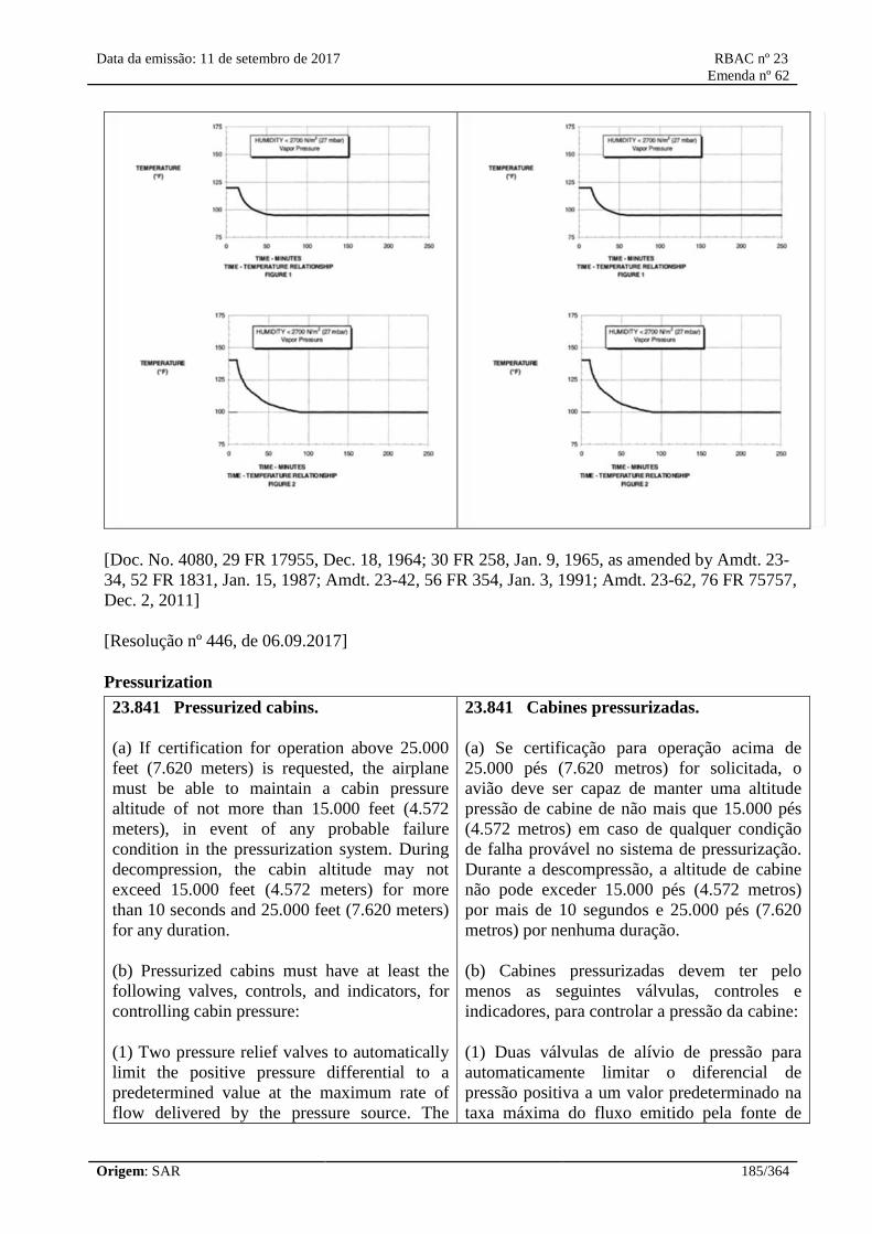
Data da emissão: 11 de setembro de 2017 RBAC nº 23
Emenda nº 62
Origem: SAR 185/364
[Doc. No. 4080, 29 FR 17955, Dec. 18, 1964; 30 FR 258, Jan. 9, 1965, as amended by Amdt. 23-
34, 52 FR 1831, Jan. 15, 1987; Amdt. 23-42, 56 FR 354, Jan. 3, 1991; Amdt. 23-62, 76 FR 75757,
Dec. 2, 2011]
[Resolução nº 446, de 06.09.2017]
Pressurization
23.841 Pressurized cabins.
(a) If certification for operation above 25.000
feet (7.620 meters) is requested, the airplane
must be able to maintain a cabin pressure
altitude of not more than 15.000 feet (4.572
meters), in event of any probable failure
condition in the pressurization system. During
decompression, the cabin altitude may not
exceed 15.000 feet (4.572 meters) for more
than 10 seconds and 25.000 feet (7.620 meters)
for any duration.
(b) Pressurized cabins must have at least the
following valves, controls, and indicators, for
controlling cabin pressure:
(1) Two pressure relief valves to automatically
limit the positive pressure differential to a
predetermined value at the maximum rate of
flow delivered by the pressure source. The
23.841 Cabines pressurizadas.
(a) Se certificação para operação acima de
25.000 pés (7.620 metros) for solicitada, o
avião deve ser capaz de manter uma altitude
pressão de cabine de não mais que 15.000 pés
(4.572 metros) em caso de qualquer condição
de falha provável no sistema de pressurização.
Durante a descompressão, a altitude de cabine
não pode exceder 15.000 pés (4.572 metros)
por mais de 10 segundos e 25.000 pés (7.620
metros) por nenhuma duração.
(b) Cabines pressurizadas devem ter pelo
menos as seguintes válvulas, controles e
indicadores, para controlar a pressão da cabine:
(1) Duas válvulas de alívio de pressão para
automaticamente limitar o diferencial de
pressão positiva a um valor predeterminado na
taxa máxima do fluxo emitido pela fonte de

Data da emissão: 11 de setembro de 2017 RBAC nº 23
Emenda nº 62
Origem: SAR 186/364
combined capacity of the relief valves must be
large enough so that the failure of any one
valve would not cause an appreciable rise in
the pressure differential. The pressure
differential is positive when the internal
pressure is greater than the external.
(2) Two reverse pressure differential relief
valves (or their equivalent) to automatically
prevent a negative pressure differential that
would damage the structure. However, one
valve is enough if it is of a design that
reasonably precludes its malfunctioning.
(3) A means by which the pressure differential
can be rapidly equalized.
(4) An automatic or manual regulator for
controlling the intake or exhaust airflow, or
both, for maintaining the required internal
pressures and airflow rates.
(5) Instruments to indicate to the pilot the
pressure differential, the cabin pressure
altitude, and the rate of change of cabin
pressure altitude.
(6) Warning indication at the pilot station to
indicate when the safe or preset pressure
differential is exceeded and when a cabin
pressure altitude of 10.000 feet (3.048 meters)
is exceeded. The 10.000 feet (3.048 meters)
cabin altitude warning may be increased up to
15.000 feet (4.572 meters) for operations from
high altitude airfields (10.000 to 15.000 feet –
3.048 a 4.572 meters) provided:
(i) The landing or the take off modes (normal
or high altitude) are clearly indicated to the
flight crew.
(ii) Selection of normal or high altitude airfield
mode requires no more than one flight crew
action and goes to normal airfield mode at
engine stop.
(iii) The pressurization system is designed to
ensure cabin altitude does not exceed 10,000
pressão. A capacidade combinada das válvulas
de alívio deve ser grande o suficiente para que
a falha de qualquer uma das válvulas não cause
um aumento apreciável no diferencial de
pressão. O diferencial de pressão é positivo
quando a pressão interna é maior que a externa.
(2) Duas válvulas de alívio de diferencial de
pressão reverso (ou seus equivalentes) para
automaticamente impedir um diferencial de
pressão negativo, que poderia danificar a
estrutura. No entanto, uma válvula é suficiente
se for de um projeto que exclui, com razoável
certeza, a possibilidade de um mau
funcionamento.
(3) Um meio pelo qual o diferencial de pressão
possa ser rapidamente equalizado.
(4) Um regulador automático ou manual para
controlar o fluxo de ar de admissão ou de
exaustão, ou ambos, para manter as pressões
internas e as taxas de fluxo de ar necessárias.
(5) Instrumentos para indicar ao piloto o
diferencial de pressão, a altitude pressão da
cabine, e a taxa de mudança da altitude pressão
da cabine.
(6) Indicação de alerta na cabine para indicar
quando o diferencial de pressão segura ou
selecionada é excedida e quando a altitude de
pressão de cabine de 10.000 pés (3.048 metros)
é excedida. O alarme de altitude de cabine a
10.000 pés (3.048 metros) pode ser elevado até
15.000 pés (4.572 metros) para operações em
aeródromos a alta altitude (10.000 a 15.000 pés
– 3.048 a 4.572 metros) desde que:
(i) Os modos (normal ou alta altitude) de pouso
ou decolagem sejam claramente indicados à
tripulação de voo.
(ii) A seleção dos modos normal ou alta
altitude requeira não mais que uma ação por
parte da tripulação de voo e retorne para o
modo normal quando da parada dos motores.
(iii) O sistema de pressurização seja projetado

Data da emissão: 11 de setembro de 2017 RBAC nº 23
Emenda nº 62
Origem: SAR 187/364
feet when in flight above flight level (FL) 250.
(iv) The pressurization system and cabin
altitude warning system is designed to ensure
cabin altitude warning at 10.000 feet (3.048
meters) when in flight above FL250.
(7) A warning placard for the pilot if the
structure is not designed for pressure
differentials up to the maximum relief valve
setting in combination with landing loads.
(8) A means to stop rotation of the compressor
or to divert airflow from the cabin if continued
rotation of an engine-driven cabin compressor
or continued flow of any compressor bleed air
will create a hazard if a malfunction occurs.
(c) If certification for operation above 41.000
feet (12.497 meters) and not more than 45,000
feet (13.716 meters) is requested:
(1) The airplane must prevent cabin pressure
altitude from exceeding the following after
decompression from any probable
pressurization system failure in conjunction
with any undetected, latent pressurization
system failure condition:
(i) If depressurization analysis shows that the
cabin altitude does not exceed 25.000 feet
(7.620 meters), the pressurization system must
prevent the cabin altitude from exceeding the
cabin altitude-time history shown in Figure 1 of
this section.
(ii) Maximum cabin altitude is limited to
30.000 feet (9.144 meters). If cabin altitude
exceeds 25.000 feet (7.620 meters), the
maximum time the cabin altitude may exceed
25.000 feet (7.620 meters) is 2 minutes; time
starting when the cabin altitude exceeds 25.000
feet (7.620 meters) and ending when it returns
to 25.000 feet (7.620 meters).
(2) The airplane must prevent cabin pressure
altitude from exceeding the following after
decompression from any single pressurization
system failure in conjunction with any probable
para garantir que a altitude de cabine não
exceda 10.000 pés (3.048 metros) quando em
voo acima do nível de voo (FL) 250.
(iv) O sistema de pressurização e alerta de
altitude de cabine seja projetado para garantir
um alarme a 10.000 pés (3.048 metros) quando
em voo acima do FL 250.
(7) Um placar de alarme para o piloto se a
estrutura não for projetada para diferenciais de
pressão de até o ajuste máximo da válvula de
alívio em combinação com as cargas de pouso.
(8) Um meio de parar a rotação do compressor
ou desviar o fluxo de ar da cabine caso a
rotação contínua do compressor de cabine
movido pelo motor ou o fluxo contínuo de
qualquer ar de sangria do compressor possa
criar um perigo caso um mau funcionamento
ocorra.
(c) Se certificação para operação acima de
41.000 pés (12.497 metros) e não mais que
45.000 pés (13.716 metros) é solicitada-
(1) O avião deve impedir que a altitude pressão
de cabine exceda o que se segue após
descompressão causada por qualquer falha
provável do sistema de pressurização em
conjunção com qualquer condição de falha
latente e não detectada do sistema de
pressurização:
(i) Se a análise de despressurização mostrar que
a altitude de cabine não excede 25.000 pés
(7.620 metros), o sistema de pressurização
deve impedir que a altitude de cabine exceda os
valores mostrados no gráfico de altitude de
cabine da Figura 1 desta seção.
(ii) A máxima altitude de cabine é limitada a
30.000 pés (9.144 metros). Se a altitude de
cabine exceder 25.000 pés (7.620 metros), o
tempo máximo durante o qual a altitude de
cabine pode exceder 25.000 pés (7.620 metros)
é de 2 minutos; iniciando a contagem do tempo
quando a altitude de cabine exceder 25.000 pés
(7.620 metros) e terminando quando ela
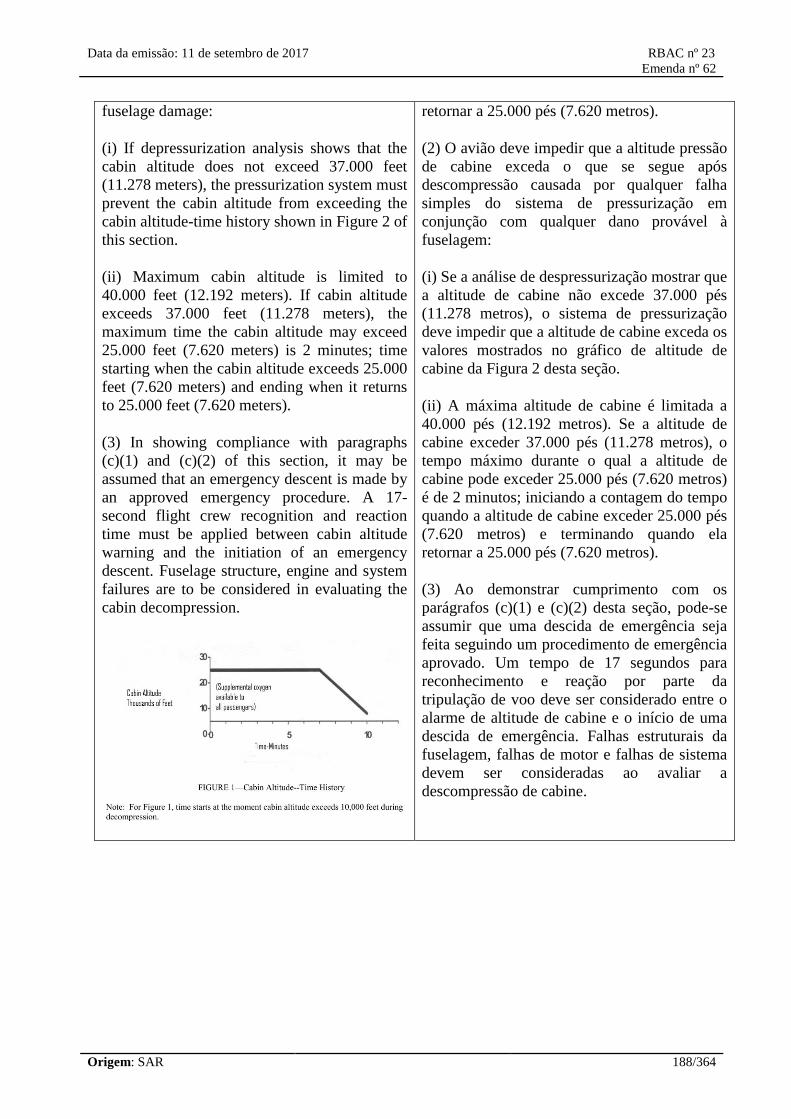
Data da emissão: 11 de setembro de 2017 RBAC nº 23
Emenda nº 62
Origem: SAR 188/364
fuselage damage:
(i) If depressurization analysis shows that the
cabin altitude does not exceed 37.000 feet
(11.278 meters), the pressurization system must
prevent the cabin altitude from exceeding the
cabin altitude-time history shown in Figure 2 of
this section.
(ii) Maximum cabin altitude is limited to
40.000 feet (12.192 meters). If cabin altitude
exceeds 37.000 feet (11.278 meters), the
maximum time the cabin altitude may exceed
25.000 feet (7.620 meters) is 2 minutes; time
starting when the cabin altitude exceeds 25.000
feet (7.620 meters) and ending when it returns
to 25.000 feet (7.620 meters).
(3) In showing compliance with paragraphs
(c)(1) and (c)(2) of this section, it may be
assumed that an emergency descent is made by
an approved emergency procedure. A 17-
second flight crew recognition and reaction
time must be applied between cabin altitude
warning and the initiation of an emergency
descent. Fuselage structure, engine and system
failures are to be considered in evaluating the
cabin decompression.
retornar a 25.000 pés (7.620 metros).
(2) O avião deve impedir que a altitude pressão
de cabine exceda o que se segue após
descompressão causada por qualquer falha
simples do sistema de pressurização em
conjunção com qualquer dano provável à
fuselagem:
(i) Se a análise de despressurização mostrar que
a altitude de cabine não excede 37.000 pés
(11.278 metros), o sistema de pressurização
deve impedir que a altitude de cabine exceda os
valores mostrados no gráfico de altitude de
cabine da Figura 2 desta seção.
(ii) A máxima altitude de cabine é limitada a
40.000 pés (12.192 metros). Se a altitude de
cabine exceder 37.000 pés (11.278 metros), o
tempo máximo durante o qual a altitude de
cabine pode exceder 25.000 pés (7.620 metros)
é de 2 minutos; iniciando a contagem do tempo
quando a altitude de cabine exceder 25.000 pés
(7.620 metros) e terminando quando ela
retornar a 25.000 pés (7.620 metros).
(3) Ao demonstrar cumprimento com os
parágrafos (c)(1) e (c)(2) desta seção, pode-se
assumir que uma descida de emergência seja
feita seguindo um procedimento de emergência
aprovado. Um tempo de 17 segundos para
reconhecimento e reação por parte da
tripulação de voo deve ser considerado entre o
alarme de altitude de cabine e o início de uma
descida de emergência. Falhas estruturais da
fuselagem, falhas de motor e falhas de sistema
devem ser consideradas ao avaliar a
descompressão de cabine.

Data da emissão: 11 de setembro de 2017 RBAC nº 23
Emenda nº 62
Origem: SAR 189/364
(d) If certification for operation above 45.000
feet (13.176 meters) and not more than 51.000
feet (15.545 meters) is requested:
(1) Pressurized cabins must be equipped to
provide a cabin pressure altitude of not more
than 8.000 feet (2.438 meters) at the maximum
operating altitude of the airplane under normal
operating conditions.
(2) The airplane must prevent cabin pressure
altitude from exceeding the following after
decompression from any failure condition not
shown to be extremely improbable:
(i) Twenty-five thousand (25.000) feet (7.620
meters) for more than 2 minutes; or
(ii) Forty thousand (40.000) feet (12.192
meters) for any duration.
(3) Fuselage structure, engine and system
failures are to be considered in evaluating the
cabin decompression.
(4) In addition to the cabin altitude indicating
means in paragraph (b)(6) of this section, an
aural or visual signal must be provided to warn
the flight crew when the cabin pressure altitude
exceeds 10.000 feet (3.048 meters).
(5) The sensing system and pressure sensors
necessary to meet the requirements of
paragraphs (b)(5), (b)(6), and (d)(4) of this
section and paragraph 23.1447(e) of this
RBAC, must, in the event of low cabin
pressure, actuate the required warning and
(d) Se certificação para operação acima de
45.000 pés (13.176 metros) e não mais que
51.000 pés (15.545 metros) é solicitada:
(1) Cabines pressurizadas devem ser equipadas
para prover uma altitude pressão de cabine de
não mais que 8.000 pés (2.438 metros) na
máxima altitude de operação do avião sob
condições normais de operação.
(2) O avião deve impedir que a altitude pressão
de cabine exceda o que se segue após
descompressão causada por qualquer condição
de falha que não tenha sido demonstrada ser
extremamente improvável:
(i) Vinte e cinco mil (25.000) pés (7.620
metros) por mais de 2 minutos; ou
(ii) Quarenta mil (40.0000) pés (12.192 metros)
por qualquer duração.
(3) Falhas estruturais da fuselagem, falhas de
motor e falhas de sistema devem ser
consideradas ao avaliar a descompressão de

Data da emissão: 11 de setembro de 2017 RBAC nº 23
Emenda nº 62
Origem: SAR 190/364
automatic presentation devices without any
delay that would significantly increase the
hazards resulting from decompression.
cabine.
(4) Em adição aos meios de indicação de
altitude de cabine em (b)(6) desta seção, um
sinal aural ou visual deve ser provido para
alertar a tripulação de voo quando a altitude
pressão de cabine exceder 10.000 pés (3.048
metros).
(5) O sistema de sensoriamento e os sensores
de pressão necessários para atender os
requisitos de (b)(5), (b)(6) e (d)(4) desta seção
e parágrafo 23.1447(e), devem, no evento de
baixa pressão de cabine, disparar o alarme
requerido e os dispositivos de apresentação
automática sem qualquer atraso que aumentaria
significativamente os perigos resultantes da
descompressão.
[Amdt. 23-14, 38 FR 31822, Nov. 19, 1973, as amended by Amdt. 23-17, 41 FR 55464, Dec. 20,
1976; Amdt. 23-49, 61 FR 5167, Feb. 9, 1996; Amdt. 23-62, 76 FR 75757, Dec. 2, 2011]
[Resolução nº 446, de 06.09.2017]
§ 23.843 Pressurization tests.
(a) Strength test. The complete pressurized cabin, including doors, windows, canopy, and valves,
must be tested as a pressure vessel for the pressure differential specified in §23.365(d).
(b) Functional tests. The following functional tests must be performed:
(1) Tests of the functioning and capacity of the positive and negative pressure differential valves,
and of the emergency release valve, to simulate the effects of closed regulator valves.
(2) Tests of the pressurization system to show proper functioning under each possible condition of
pressure, temperature, and moisture, up to the maximum altitude for which certification is
requested.
(3) Flight tests, to show the performance of the pressure supply, pressure and flow regulators,
indicators, and warning signals, in steady and stepped climbs and descents at rates corresponding to
the maximum attainable within the operating limitations of the airplane, up to the maximum altitude
for which certification is requested.
(4) Tests of each door and emergency exit, to show that they operate properly after being subjected
to the flight tests prescribed in paragraph (b)(3) of this section.
Fire Protection
§ 23.851 Fire extinguishers.

Data da emissão: 11 de setembro de 2017 RBAC nº 23
Emenda nº 62
Origem: SAR 191/364
(a) There must be at least one hand fire extinguisher for use in the pilot compartment that is located
within easy access of the pilot while seated.
(b) There must be at least one hand fire extinguisher located conveniently in the passenger
compartment—
(1) Of each airplane accommodating more than 6 passengers; and
(2) Of each commuter category airplane.
(c) For hand fire extinguishers, the following apply:
(1) The type and quantity of each extinguishing agent used must be appropriate to the kinds of fire
likely to occur where that agent is to be used.
(2) Each extinguisher for use in a personnel compartment must be designed to minimize the hazard
of toxic gas concentrations.
[Doc. No. 26269, 58 FR 42165, Aug. 6, 1993]
23.853 Passenger and crew compartment
interiors.
For each compartment to be used by the crew
or passengers:
(a) The materials must be at least flame-
resistant;
(b) [Reserved]
(c) If smoking is to be prohibited, there must be
a placard so stating, and if smoking is to be
allowed:
(1) There must be an adequate number of self-
contained, removable ashtrays; and
(2) Where the crew compartment is separated
from the passenger compartment, there must be
at least one illuminated sign (using either
letters or symbols) notifying all passengers
when smoking is prohibited. Signs which
notify when smoking is prohibited must—
(i) When illuminated, be legible to each
passenger seated in the passenger cabin under
23.853 Interiores de compartimentos da
tripulação e de passageiros.
Para cada compartimento a ser usado pela
tripulação ou passageiros:
(a) Os materiais devem ser pelo menos
resistentes à chama;
(b) [Reservado]
(c) Se fumar for proibido, deve haver um placar
declarando a proibição, e se fumar for
permitido:
(1) Deve haver um número adequado de
cinzeiros fechados e removíveis; e
(2) Onde o compartimento de tripulação é
separado do compartimento de passageiros,
deve haver pelo menos um sinal iluminado
(usando letras ou símbolos) avisando a todos os
passageiros quando fumar é proibido. Os sinais
que avisam quando fumar é proibido devem:
(i) Quando iluminado, ser legíveis a cada
passageiro sentado na cabine de passageiros em

Data da emissão: 11 de setembro de 2017 RBAC nº 23
Emenda nº 62
Origem: SAR 192/364
all probable lighting conditions; and
(ii) Be so constructed that the crew can turn the
illumination on and off; and
(d) In addition, for commuter category
airplanes the following requirements apply:
(1) Each disposal receptacle for towels, paper,
or waste must be fully enclosed and
constructed of at least fire resistant materials
and must contain fires likely to occur in it
under normal use. The ability of the disposal
receptacle to contain those fires under all
probable conditions of wear, misalignment, and
ventilation expected in service must be
demonstrated by test. A placard containing the
legible words “No Cigarette Disposal” must be
located on or near each disposal receptacle
door.
(2) Lavatories must have “No Smoking” or
“No Smoking in Lavatory” placards located
conspicuously on each side of the entry door.
(3) Materials (including finishes or decorative
surfaces applied to the materials) used in each
compartment occupied by the crew or
passengers must meet the following test criteria
as applicable:
(i) Interior ceiling panels, interior wall panels,
partitions, galley structure, large cabinet walls,
structural flooring, and materials used in the
construction of stowage compartments (other
than underseat stowage compartments and
compartments for stowing small items such as
magazines and maps) must be self-
extinguishing when tested vertically in
accordance with the applicable portions of
appendix F of this RBAC or by other
equivalent methods. The average burn length
may not exceed 6 inches (150 mm) and the
average flame time after removal of the flame
source may not exceed 15 seconds. Drippings
from the test specimen may not continue to
flame for more than an average of 3 seconds
after falling.
todas as condições de iluminação prováveis; e
(ii) Ser construídos de modo que a tripulação
possa ligar e desligar a iluminação.
(d) Em adição, para aviões da categoria
transporte regional as seguintes exigências
aplicam-se:
(1) Cada recipiente para descarte de toalhas,
papel, ou resíduos deve ser completamente
fechado e construído com materiais pelo menos
resistentes a fogo e deve conter o fogo provável
de ocorrer em seu interior, durante o uso
normal. A capacidade do recipiente para
descarte, de conter esse fogo em todas as
condições prováveis de uso, desalinhamento, e
ventilação esperada em serviço deve ser
demonstrada por ensaio. Um placar contendo
as palavras legíveis 'Proibido jogar cigarro’
deve estar localizado em ou perto de cada porta
do recipiente disponível.
(2) Os lavatórios devem ter placares de "É
Proibido Fumar" ou "É Proibido Fumar no
Lavatório” localizado visivelmente em cada
lado da porta de entrada
(3) Os materiais (inclusive acabamentos ou
superfícies decorativas aplicadas aos materiais)
usados em cada compartimento ocupado pela
tripulação ou passageiros devem atender aos
seguintes critérios de ensaio como aplicável:
(i) Os painéis internos do teto, os painéis
internos de parede, as divisórias, a estrutura da
copa, as grandes paredes dos gabinetes, a
estrutura do piso, e os materiais usados na
construção do compartimento de carga (exceto
os compartimentos de bagagem embaixo do
assento e compartimentos para alojar pequenos
itens como revistas e mapas) devem ser auto
extinguíveis quando testados verticalmente de
acordo com as partes aplicáveis do apêndice F
deste RBAC ou por outros métodos
equivalentes. O comprimento médio de queima
não pode exceder 6 polegadas (150 mm) e o
tempo médio de chama depois da retirada da
fonte de chama não pode exceder 15 segundos.
Data da emissão: 11 de setembro de 2017 RBAC nº 23
Emenda nº 62
Origem: SAR 193/364
(ii) Floor covering, textiles (including draperies
and upholstery), seat cushions, padding,
decorative and nondecorative coated fabrics,
leather, trays and galley furnishings, electrical
conduit, thermal and acoustical insulation and
insulation covering, air ducting, joint and edge
covering, cargo compartment liners, insulation
blankets, cargo covers and transparencies,
molded and thermoformed parts, air ducting
joints, and trim strips (decorative and chafing),
that are constructed of materials not covered in
paragraph (d)(3)(iv) of this section must be self
extinguishing when tested vertically in
accordance with the applicable portions of
appendix F of this RBAC or other approved
equivalent methods. The average burn length
may not exceed 8 inches (200 mm) and the
average flame time after removal of the flame
source may not exceed 15 seconds. Drippings
from the test specimen may not continue to
flame for more than an average of 5 seconds
after falling.
(iii) Motion picture film must be safety film
meeting the Standard Specifications for Safety
Photographic Film PH1.25 (available from the
American National Standards Institute, 1430
Broadway, New York, N.Y. 10018, USA) or an
ANAC approved equivalent. If the film travels
through ducts, the ducts must meet the
requirements of paragraph (d)(3)(ii) of this
section.
(iv) Acrylic windows and signs, parts
constructed in whole or in part of elastomeric
materials, edge-lighted instrument assemblies
consisting of two or more instruments in a
common housing, seatbelts, shoulder harnesses,
and cargo and baggage tiedown equipment,
including containers, bins, pallets, etc., used in
passenger or crew compartments, may not have
an average burn rate greater than 2,5 inches per
minute (60 mm/min) when tested horizontally
in accordance with the applicable portions of
appendix F of this RBAC or by other approved
equivalent methods.
(v) Except for electrical wire cable insulation,
and for small parts (such as knobs, handles,
O gotejamento vindo do corpo de prova não
pode continuar em chamas por um tempo
superior a uma média de 3 segundos depois da
queda.
(ii) A cobertura do piso, tecidos (inclusive
tapeçaria e estofamento), almofadas de assento,
enchimento, tecidos de revestimento
decorativos e não decorativos, couro, bandejas
e mobiliário da copa, conduíte elétrico,
isolamento térmico e acústico e cobertura do
isolamento, dutos de ar, união e cobertura de
arestas, forro do compartimento de carga,
isolante termo acústico, coberturas de carga e
objetos transparentes, partes moldadas e termo
moldadas, uniões de dutos de ar, e faixas de
acabamento (decorativo e de atrito), que são
construídos de materiais não cobertos no
parágrafo (d)(3)(iv) desta seção devem ser auto
extinguíveis quando ensaiados verticalmente de
acordo com as partes aplicáveis do Apêndice F
deste RBAC ou outros métodos equivalentes
aprovados. O comprimento médio da queima
não pode exceder 8 polegadas (200 mm) e o
tempo médio de chama depois de retirada a
fonte da chama não pode exceder 15 segundos.
O gotejamento vindo do corpo de prova não
pode continuar em chamas por um tempo
superior a uma média de 5 segundos depois da
queda.
(iii) A película de filme cinematográfico deve
ser uma película de segurança que satisfaça as
Especificações Padrões de Filme Fotográfico
de Segurança PH1.25 (disponível no American
National Standards Institute, 1430 Broadway,
New York, N.Y. 10018, EUA) ou um
equivalente aprovado pela ANAC. Se o filme
passar através de dutos, os dutos devem atender
aos requisitos do parágrafo (d)(3)(ii) desta
seção.
(iv) As janelas acrílicas e os sinais, peças
construídas no todo ou em parte por material
elastomérico, reunião de instrumentos com
iluminação de canto composto de dois ou mais
instrumentos em um alojamento comum, cintos
de segurança, cintos de ombro, e equipamento
para prender carga e bagagem, inclusive
Data da emissão: 11 de setembro de 2017 RBAC nº 23
Emenda nº 62
Origem: SAR 194/364
rollers, fasteners, clips, grommets, rub strips,
pulleys, and small electrical parts) that the
Administrator finds would not contribute
significantly to the propagation of a fire,
materials in items not specified in paragraphs
(d)(3)(i), (ii), (iii), or (iv) of this section may
not have a burn rate greater than 4,0 inches per
minute (100 mm/min) when tested horizontally
in accordance with the applicable portions of
appendix F of this RBAC or by other approved
equivalent methods.
(e) Lines, tanks, or equipment containing fuel,
oil, or other flammable fluids may not be
installed in such compartments unless
adequately shielded, isolated, or otherwise
protected so that any breakage or failure of
such an item would not create a hazard.
(f) Airplane materials located on the cabin side
of the firewall must be self-extinguishing or be
located at such a distance from the firewall, or
otherwise protected, so that ignition will not
occur if the firewall is subjected to a flame
temperature of not less than 2.000 °F (1.093,33
°C) for 15 minutes. For self-extinguishing
materials (except electrical wire and cable
insulation and small parts that the
Administrator finds would not contribute
significantly to the propagation of a fire), a
vertifical self-extinguishing test must be
conducted in accordance with appendix F of
this RBAC or an equivalent method approved
by the Administrator. The average burn length
of the material may not exceed 6 inches (150
mm) and the average flame time after removal
of the flame source may not exceed 15 seconds.
Drippings from the material test specimen may
not continue to flame for more than an average
of 3 seconds after falling.
containeres, caixas, pallets, etc., usado nos
compartimentos de passageiros ou de
tripulação, não podem ter uma taxa média de
queima maior do que 2,5 polegadas por minuto
(60 mm/min) quando ensaiados
horizontalmente conforme as partes aplicáveis
do apêndice F deste RBAC ou por outros
métodos equivalentes aprovados.
(v) Exceto para cabo de isolamento de fio
elétrico, e para pequenas peças (como
puxadores, maçanetas, rolos, prendedores,
clipes, anéis isolantes, tiras de borracha,
roldanas, e pequenas partes elétricas) que a
ANAC entender que não contribuiriam
significativamente para a propagação de um
fogo, os materiais dos itens não especificados
em (d)(3)(i), (ii), (iii), ou (iv) desta seção não
podem ter uma taxa de queima maior do que
4,0 polegadas por minuto (100 mm/min)
quando ensaiado horizontalmente em acordo
com as partes aplicáveis do apêndice F deste
RBAC ou por outros métodos equivalentes
aprovados.
(e) As linhas, tanques, ou os equipamentos que
contêm combustível, óleo, ou outros fluidos
inflamáveis não podem ser instalados em tais
compartimentos a menos que adequadamente
protegidos, isolados, ou de outra maneira
protegidos para que qualquer quebra ou falha
de tal item não crie um risco.
(f) Os materiais do avião localizados na cabine
do lado da parede de fogo devem ser auto
extinguível ou estar localizado a certa distância
da parede de fogo, ou de outra maneira
protegidos, para que a ignição não ocorra se a
parede de fogo for submetida a uma
temperatura de chama de não menos de 2.000
°F (1.093,33 °C) durante 15 minutos. Para
materiais auto extinguíveis (exceto fio elétrico
e isolamento de cabos e pequenas partes que a
ANAC entender que não contribuiriam
significativamente para a propagação de um
fogo), um ensaio de auto extinção vertical deve
ser conduzida em acordo com o apêndice F
deste RBAC ou um método equivalente
aprovado pela ANAC. O comprimento médio

Data da emissão: 11 de setembro de 2017 RBAC nº 23
Emenda nº 62
Origem: SAR 195/364
de queima do material não pode exceder 6
polegadas (150 mm) e o tempo médio de
chama depois da retirada da fonte de chama
não pode exceder 15 segundos. O gotejamento
vindo do material do corpo de prova não pode
continuar em chamas por mais que uma média
de 3 segundos depois da queda.
[Amdt. 23-14, 23 FR 31822, Nov. 19, 1973, as amended by Amdt. 23-23, 43 FR 50593, Oct. 30,
1978; Amdt. 23-25, 45 FR 7755, Feb. 4, 1980; Amdt. 23-34, 52 FR 1831, Jan. 15, 1987; Amdt. 23-
62, 76 FR 75759, Dec. 2, 2011]
[Resolução nº 446, de 06.09.2017]
§ 23.855 Cargo and baggage compartment fire protection.
(a) Sources of heat within each cargo and baggage compartment that are capable of igniting the
compartment contents must be shielded and insulated to prevent such ignition.
(b) Each cargo and baggage compartment must be constructed of materials that meet the appropriate
provisions of §23.853(d)(3).
(c) In addition, for commuter category airplanes, each cargo and baggage compartment must:
(1) Be located where the presence of a fire would be easily discovered by the pilots when seated at
their duty station, or it must be equipped with a smoke or fire detector system to give a warning at
the pilots' station, and provide sufficient access to enable a pilot to effectively reach any part of the
compartment with the contents of a hand held fire extinguisher, or
(2) Be equipped with a smoke or fire detector system to give a warning at the pilots' station and
have ceiling and sidewall liners and floor panels constructed of materials that have been subjected
to and meet the 45 degree angle test of appendix F of this part. The flame may not penetrate (pass
through) the material during application of the flame or subsequent to its removal. The average
flame time after removal of the flame source may not exceed 15 seconds, and the average glow time
may not exceed 10 seconds. The compartment must be constructed to provide fire protection that is
not less than that required of its individual panels; or
(3) Be constructed and sealed to contain any fire within the compartment.
[Doc. No. 27806, 61 FR 5167, Feb. 9, 1996]
23.856 Thermal/acoustic insulation
materials.
Thermal/acoustic insulation material installed
in the fuselage must meet the flame
propagation test requirements of part II of
Appendix F to this RBAC, or other approved
equivalent test requirements. This requirement
23.856 Materiais de isolamento
térmico/acústico.
Materiais de isolamento térmico/acústico
instalados na fuselagem devem atender aos
requisitos de ensaio de propagação de chama
da parte II do apêndice F deste regulamento, ou
outros requisitos de teste equivalentes
Data da emissão: 11 de setembro de 2017 RBAC nº 23
Emenda nº 62
Origem: SAR 196/364
does not apply to ‘‘small parts,’’ as defined in
paragraph 23.853(d)(3)(v).
aprovados. Esta exigência não se aplica a
“peças pequenas”, conforme definido no
parágrafo 23.853(d)(3)(v).
[Amdt. 23-62, 76 FR 75759, Dec. 2, 2011]
[Resolução nº 446, de 06.09.2017]
§ 23.859 Combustion heater fire protection.
(a) Combustion heater fire regions. The following combustion heater fire regions must be protected
from fire in accordance with the applicable provisions of §§23.1182 through 23.1191 and 23.1203:
(1) The region surrounding the heater, if this region contains any flammable fluid system
components (excluding the heater fuel system) that could—
(i) Be damaged by heater malfunctioning; or
(ii) Allow flammable fluids or vapors to reach the heater in case of leakage.
(2) The region surrounding the heater, if the heater fuel system has fittings that, if they leaked,
would allow fuel vapor to enter this region.
(3) The part of the ventilating air passage that surrounds the combustion chamber.
(b) Ventilating air ducts. Each ventilating air duct passing through any fire region must be fireproof.
In addition—
(1) Unless isolation is provided by fireproof valves or by equally effective means, the ventilating air
duct downstream of each heater must be fireproof for a distance great enough to ensure that any fire
originating in the heater can be contained in the duct; and
(2) Each part of any ventilating duct passing through any region having a flammable fluid system
must be constructed or isolated from that system so that the malfunctioning of any component of
that system cannot introduce flammable fluids or vapors into the ventilating airstream.
(c) Combustion air ducts. Each combustion air duct must be fireproof for a distance great enough to
prevent damage from backfiring or reverse flame propagation. In addition—
(1) No combustion air duct may have a common opening with the ventilating airstream unless
flames from backfires or reverse burning cannot enter the ventilating airstream under any operating
condition, including reverse flow or malfunctioning of the heater or its associated components; and
(2) No combustion air duct may restrict the prompt relief of any backfire that, if so restricted, could
cause heater failure.
(d) Heater controls: general. Provision must be made to prevent the hazardous accumulation of
water or ice on or in any heater control component, control system tubing, or safety control.

Data da emissão: 11 de setembro de 2017 RBAC nº 23
Emenda nº 62
Origem: SAR 197/364
(e) Heater safety controls. (1) Each combustion heater must have the following safety controls:
(i) Means independent of the components for the normal continuous control of air temperature,
airflow, and fuel flow must be provided to automatically shut off the ignition and fuel supply to that
heater at a point remote from that heater when any of the following occurs:
(A) The heater exchanger temperature exceeds safe limits.
(B) The ventilating air temperature exceeds safe limits.
(C) The combustion airflow becomes inadequate for safe operation.
(D) The ventilating airflow becomes inadequate for safe operation.
(ii) Means to warn the crew when any heater whose heat output is essential for safe operation has
been shut off by the automatic means prescribed in paragraph (e)(1)(i) of this section.
(2) The means for complying with paragraph (e)(1)(i) of this section for any individual heater
must—
(i) Be independent of components serving any other heater whose heat output is essential for safe
operations; and
(ii) Keep the heater off until restarted by the crew.
(f) Air intakes. Each combustion and ventilating air intake must be located so that no flammable
fluids or vapors can enter the heater system under any operating condition—
(1) During normal operation; or
(2) As a result of the malfunctioning of any other component.
(g) Heater exhaust. Heater exhaust systems must meet the provisions of §§23.1121 and 23.1123. In
addition, there must be provisions in the design of the heater exhaust system to safely expel the
products of combustion to prevent the occurrence of—
(1) Fuel leakage from the exhaust to surrounding compartments;
(2) Exhaust gas impingement on surrounding equipment or structure;
(3) Ignition of flammable fluids by the exhaust, if the exhaust is in a compartment containing
flammable fluid lines; and
(4) Restrictions in the exhaust system to relieve backfires that, if so restricted, could cause heater
failure.
(h) Heater fuel systems. Each heater fuel system must meet each powerplant fuel system
requirement affecting safe heater operation. Each heater fuel system component within the
ventilating airstream must be protected by shrouds so that no leakage from those components can

Data da emissão: 11 de setembro de 2017 RBAC nº 23
Emenda nº 62
Origem: SAR 198/364
enter the ventilating airstream.
(i) Drains. There must be means to safely drain fuel that might accumulate within the combustion
chamber or the heater exchanger. In addition—
(1) Each part of any drain that operates at high temperatures must be protected in the same manner
as heater exhausts; and
(2) Each drain must be protected from hazardous ice accumulation under any operating condition.
[Amdt. 23–27, 45 FR 70387, Oct. 23, 1980]
§ 23.863 Flammable fluid fire protection.
(a) In each area where flammable fluids or vapors might escape by leakage of a fluid system, there
must be means to minimize the probability of ignition of the fluids and vapors, and the resultant
hazard if ignition does occur.
(b) Compliance with paragraph (a) of this section must be shown by analysis or tests, and the
following factors must be considered:
(1) Possible sources and paths of fluid leakage, and means of detecting leakage.
(2) Flammability characteristics of fluids, including effects of any combustible or absorbing
materials.
(3) Possible ignition sources, including electrical faults, overheating of equipment, and
malfunctioning of protective devices.
(4) Means available for controlling or extinguishing a fire, such as stopping flow of fluids, shutting
down equipment, fireproof containment, or use of extinguishing agents.
(5) Ability of airplane components that are critical to safety of flight to withstand fire and heat.
(c) If action by the flight crew is required to prevent or counteract a fluid fire (e.g. equipment
shutdown or actuation of a fire extinguisher), quick acting means must be provided to alert the
crew.
(d) Each area where flammable fluids or vapors might escape by leakage of a fluid system must be
identified and defined.
[Amdt. 23–23, 43 FR 50593, Oct. 30, 1978]
§ 23.865 Fire protection of flight controls, engine mounts, and other flight structure.
Flight controls, engine mounts, and other flight structure located in designated fire zones, or in
adjacent areas that would be subjected to the effects of fire in the designated fire zones, must be
constructed of fireproof material or be shielded so that they are capable of withstanding the effects
of a fire. Engine vibration isolators must incorporate suitable features to ensure that the engine is
Data da emissão: 11 de setembro de 2017 RBAC nº 23
Emenda nº 62
Origem: SAR 199/364
retained if the non-fireproof portions of the isolators deteriorate from the effects of a fire.
[Doc. No. 27805, 61 FR 5148, Feb. 9, 1996]
Electrical Bonding and Lightning Protection
§ 23.867 Electrical bonding and protection against lightning and static electricity.
(a) The airplane must be protected against catastrophic effects from lightning.
(b) For metallic components, compliance with paragraph (a) of this section may be shown by—
(1) Bonding the components properly to the airframe; or
(2) Designing the components so that a strike will not endanger the airplane.
(c) For nonmetallic components, compliance with paragraph (a) of this section may be shown by—
(1) Designing the components to minimize the effect of a strike; or
(2) Incorporating acceptable means of diverting the resulting electrical current so as not to endanger
the airplane.
[Amdt. 23–7, 34 FR 13092, Aug. 13, 1969]
Miscellaneous
§ 23.871 Leveling means.
There must be means for determining when the airplane is in a level position on the ground.
[Amdt. 23–7, 34 FR 13092, Aug. 13, 1969]
Subpart E—Powerplant
General
§ 23.901 Installation.
(a) For the purpose of this part, the airplane powerplant installation includes each component that—
(1) Is necessary for propulsion; and
(2) Affects the safety of the major propulsive units.
(b) Each powerplant installation must be constructed and arranged to—
(1) Ensure safe operation to the maximum altitude for which approval is requested.
(2) Be accessible for necessary inspections and maintenance.

Data da emissão: 11 de setembro de 2017 RBAC nº 23
Emenda nº 62
Origem: SAR 200/364
(c) Engine cowls and nacelles must be easily removable or openable by the pilot to provide
adequate access to and exposure of the engine compartment for preflight checks.
(d) Each turbine engine installation must be constructed and arranged to—
(1) Result in carcass vibration characteristics that do not exceed those established during the type
certification of the engine.
(2) Ensure that the capability of the installed engine to withstand the ingestion of rain, hail, ice, and
birds into the engine inlet is not less than the capability established for the engine itself under
§23.903(a)(2).
(e) The installation must comply with—
(1) The instructions provided under the engine type certificate and the propeller type certificate.
(2) The applicable provisions of this subpart.
(f) Each auxiliary power unit installation must meet the applicable portions of this part.
[Doc. No. 4080, 29 FR 17955, Dec. 18, 1964, as amended by Amdt. 23–7, 34 FR 13092, Aug. 13,
1969; Amdt. 23–18, 42 FR 15041, Mar. 17, 1977; Amdt. 23–29, 49 FR 6846, Feb. 23, 1984; Amdt.
23–34, 52 FR 1832, Jan. 15, 1987; Amdt. 23–34, 52 FR 34745, Sept. 14, 1987; Amdt. 23–43, 58 FR
18970, Apr. 9, 1993; Amdt. 23–51, 61 FR 5136, Feb. 9, 1996; Amdt. 23–53, 63 FR 14797, Mar. 26,
1998]
23.903 Engines.
(a) Engine type certificate.
(1) Each engine must have a type certificate
and must meet the applicable requirements of
RBAC 34.
(2) Each turbine engine and its installation
must comply with one of the following:
(i) Sections 33.76, 33.77 and 33.78 of the
RBHA 33 in effect on December 13, 2000, or
as subsequently amended; or
(ii) Sections 33.77 and 33.78 of the RBHA 33
in effect on April 30, 1998, or as subsequently
amended before December 13, 2000; or
(iii) Section 33.77 of the RBHA 33 in effect on
October 31, 1974, or as subsequently amended
before April 30, 1998, unless that engine's
foreign object ingestion service history has
23.903 Motores.
(a) Certificado de tipo do motor
(1) Cada motor deve possuir um certificado de
tipo e deve satisfazer os requisitos aplicáveis
do RBAC 34.
(2) Cada motor à turbina e sua instalação deve
cumprir com uma das seguintes opções:
(i) Seções 33.76, 33.77 e 33.78 do RBHA 33
efetivos em 13 de Dezembro de 2000, ou
emendas subsequentes; ou
(ii) Seções 33.77 e 33.78 do RBHA 33 efetivos
em 30 de Abril de 1998, ou emendas
subsequentes antes de 13 de Dezembro de
2000; ou
(iii) Seção 33.77 do RBHA 33 efetivos em 31
de Outubro de 1974 ou emendas subsequentes
antes de 30 de Abril de 1998, a não ser que a

Data da emissão: 11 de setembro de 2017 RBAC nº 23
Emenda nº 62
Origem: SAR 201/364
resulted in an unsafe condition; or
(iv) Be shown to have a foreign object
ingestion service history in similar installation
locations which has not resulted in any unsafe
condition.
(b) Turbine engine installations. For turbine
engine installations:
(1) Design precautions must be taken to
minimize the hazards to the airplane in the
event of an engine rotor failure or of a fire
originating inside the engine which burns
through the engine case.
(2) The powerplant systems associated with
engine control devices, systems, and
instrumentation must be designed to give
reasonable assurance that those operating
limitations that adversely affect turbine rotor
structural integrity will not be exceeded in
service.
(3) For engines embedded in the fuselage
behind the cabin, the effects of a fan exiting
forward of the inlet case (fan disconnect) must
be addressed, the passengers must be protected,
and the airplane must be controllable to allow
for continued safe flight and landing.
(c) Engine isolation. The powerplants must be
arranged and isolated from each other to allow
operation, in at least one configuration, so that
the failure or malfunction of any engine, or the
failure or malfunction (including destruction by
fire in the engine compartment) of any system
that can affect an engine (other than a fuel tank
if only one fuel tank is installed), will not:
(1) Prevent the continued safe operation of the
remaining engines; or
(2) Require immediate action by any
crewmember for continued safe operation of
the remaining engines.
(d) Starting and stopping (piston engine).
vida em serviço do motor indique que a
ingestão de objetos externos resulta em uma
condição insegura; ou
(iv) Ser demonstrado, através de um histórico
em serviço, que ingestão de objetos externos
em instalações similares não resulta em alguma
condição insegura.
(b) Instalações de turbinas. Para instalações de
turbinas:
(1) Devem ser tomadas precauções no projeto
com o objetivo de minimizar os perigos para o
avião, causados por uma falha de rotor do
motor ou por fogo originado dentro do motor
que atravessa a carcaça do motor.
(2) Os sistemas do grupo motopropulsor
associados com dispositivos, sistemas e
instrumentação do controle do motor devem ser
projetados para prover uma garantia razoável
que as limitações operacionais que afetam
negativamente a integridade estrutural do rotor
da turbina não sejam excedidas em serviço.
(3) Para motores incorporados na fuselagem
atrás da cabine, os efeitos de um fan saindo
para a frente da carcaça da entrada de ar
(desconexão do fan) devem ser tratados, os
passageiros devem ser protegidos e o avião
deve ser controlável para permitir o voo
continuado e o pouso seguros.
(c) Separação dos motores. Os grupos
motopropulsores devem ser arranjados e
separados um do outro para permitir a
operação, ao menos em uma configuração, de
forma que a falha ou mau funcionamento de
qualquer motor, ou a falha ou mau
funcionamento (incluindo destruição por fogo
no compartimento do motor) de qualquer
sistema que possa afetar um motor (exceto um
tanque de combustível se houver apenas um
tanque de combustível instalado) não irá:
(1) Impedir a continuidade da operação segura
dos motores remanescentes; ou

Data da emissão: 11 de setembro de 2017 RBAC nº 23
Emenda nº 62
Origem: SAR 202/364
(1) The design of the installation must be such
that risk of fire or mechanical damage to the
engine or airplane, as a result of starting the
engine in any conditions in which starting is to
be permitted, is reduced to a minimum. Any
techniques and associated limitations for
engine starting must be established and
included in the Airplane Flight Manual,
approved manual material, or applicable
operating placards. Means must be provided
for:
(i) Restarting any engine of a multiengine
airplane in flight, and
(ii) Stopping any engine in flight, after engine
failure, if continued engine rotation would
cause a hazard to the airplane.
(2) In addition, for commuter category
airplanes, the following apply:
(i) Each component of the stopping system on
the engine side of the firewall that might be
exposed to fire must be at least fire resistant.
(ii) If hydraulic propeller feathering systems
are used for this purpose, the feathering lines
must be at least fire resistant under the
operating conditions that may be expected to
exist during feathering.
(e) Starting and stopping (turbine engine).
Turbine engine installations must comply with
the following:
(1) The design of the installation must be such
that risk of fire or mechanical damage to the
engine or the airplane, as a result of starting the
engine in any conditions in which starting is to
be permitted, is reduced to a minimum. Any
techniques and associated limitations must be
established and included in the Airplane Flight
Manual, approved manual material, or
applicable operating placards.
(2) There must be means for stopping
combustion within any engine and for stopping
the rotation of any engine if continued rotation
(2) Requerer ação imediata por qualquer
membro da tripulação para a continuidade da
operação segura dos motores remanescentes.
(d) Partida e parada (motor a pistão).
(1) O projeto da instalação deve ser tal que o
risco de fogo ou dano mecânico ao motor ou ao
avião, como resultado da partida do motor em
qualquer condição em que a partida é
permitida, seja reduzido a um mínimo.
Quaisquer técnicas e limitações associadas para
a partida do motor devem ser estabelecidas e
incluídas no Manual de Voo, manual aprovado,
ou placares operacionais aplicáveis. Devem ser
fornecidos meios para:
(i) Partir novamente em voo qualquer motor de
um avião com múltiplos motores; e
(ii) Parar qualquer motor em voo, após uma
falha de motor, se a rotação continuada do
motor causar um perigo ao avião.
(2) Além disso, para aviões categoria transporte
regional, o seguinte se aplica:
(i) Cada componente do sistema de parada na
parede de fogo do lado do motor que pode ser
exposta ao fogo deve ser ao menos resistente a
fogo.
(ii) Se sistemas hidráulicos para o
embandeiramento de hélice forem utilizados
para essa finalidade, as linhas de
embandeiramento devem ser ao menos
resistentes a fogo nas condições de operação
que são esperadas durante o embandeiramento.
(e) Partida e parada (turbina). Instalações de
turbinas devem cumprir com o seguinte:
(1) O projeto da instalação deve ser tal que o
risco de fogo ou dano mecânico ao motor ou ao
avião, como resultado da partida do motor em
qualquer condição em que a partida é
permitida, seja reduzido a um mínimo.
Quaisquer técnicas e limitações associadas para
a partida do motor devem ser estabelecidas e

Data da emissão: 11 de setembro de 2017 RBAC nº 23
Emenda nº 62
Origem: SAR 203/364
would cause a hazard to the airplane. Each
component of the engine stopping system
located in any fire zone must be fire resistant.
If hydraulic propeller feathering systems are
used for stopping the engine, the hydraulic
feathering lines or hoses must be fire resistant.
(3) It must be possible to restart an engine in
flight. Any techniques and associated
limitations must be established and included in
the Airplane Flight Manual, approved manual
material, or applicable operating placards.
(4) It must be demonstrated in flight that when
restarting engines following a false start, all
fuel or vapor is discharged in such a way that it
does not constitute a fire hazard.
(f) Restart envelope. An altitude and airspeed
envelope must be established for the airplane
for in-flight engine restarting and each installed
engine must have a restart capability within
that envelope.
(g) Restart capability. For turbine engine
powered airplanes, if the minimum
windmilling speed of the engines, following the
in-flight shutdown of all engines, is insufficient
to provide the necessary electrical power for
engine ignition, a power source independent of
the engine-driven electrical power generating
system must be provided to permit in-flight
engine ignition for restarting.
incluídas no manual de voo aprovado, material
de manual aprovado, ou placares operacionais
aplicáveis.
(2) Deve haver meios de parar a combustão
dentro de qualquer motor e de parar a rotação
de qualquer motor se a rotação continuada
causar perigo ao avião. Cada componente do
sistema de parada do motor localizado em
qualquer zona de fogo deve ser resistente a
fogo. Se os sistemas hidráulicos para
embandeiramento de hélice forem utilizados
para parar o motor, as linhas hidráulicas de
embandeiramento ou mangueiras devem ser
resistentes a fogo.
(3) Deve ser possível partir novamente um
motor em voo. Quaisquer técnicas e limitações
associadas devem ser estabelecidas e incluídas
no manual de Voo, manual aprovado, ou
placares operacionais aplicáveis.
(4) Deve ser demonstrado em voo que em uma
nova partida do motor, após uma partida falsa,
todo combustível ou vapor seja descarregado
de forma que não constitua um perigo de fogo.
(f) Envelope de nova partida. Deve-se
estabelecer para o avião um envelope de
altitude e velocidade para a nova partida do
motor em voo e cada motor instalado deve
possuir a capacidade de partir novamente
dentro desse envelope.
(g) Capacidade de nova partida. Para aviões a
turbina, se a mínima velocidade de livre
rotação (windmilling) para os motores, após
um apagamento em voo de todos os motores,
for insuficiente para fornecer a energia elétrica
necessária para a ignição do motor, uma fonte
de energia independente do sistema de geração
de energia elétrica acionado pelo motor deve
ser fornecida para permitir a ignição do motor
em voo para a nova partida.
[Amdt. 23–14, 38 FR 31822, Nov. 19, 1973]
[Resolução nº 446, de 06.09.2017]
Data da emissão: 11 de setembro de 2017 RBAC nº 23
Emenda nº 62
Origem: SAR 204/364
§ 23.904 Automatic power reserve system.
If installed, an automatic power reserve (APR) system that automatically advances the power or
thrust on the operating engine(s), when any engine fails during takeoff, must comply with appendix
H of this part.
[Doc. No. 26344, 58 FR 18970, Apr. 9, 1993]
§ 23.905 Propellers.
(a) Each propeller must have a type certificate.
(b) Engine power and propeller shaft rotational speed may not exceed the limits for which the
propeller is certificated.
(c) Each featherable propeller must have a means to unfeather it in flight.
(d) The propeller blade pitch control system must meet the requirements of §§35.21, 35.23, 35.42
and 35.43 of this chapter.
(e) All areas of the airplane forward of the pusher propeller that are likely to accumulate and shed
ice into the propeller disc during any operating condition must be suitably protected to prevent ice
formation, or it must be shown that any ice shed into the propeller disc will not create a hazardous
condition.
(f) Each pusher propeller must be marked so that the disc is conspicuous under normal daylight
ground conditions.
(g) If the engine exhaust gases are discharged into the pusher propeller disc, it must be shown by
tests, or analysis supported by tests, that the propeller is capable of continuous safe operation.
(h) All engine cowling, access doors, and other removable items must be designed to ensure that
they will not separate from the airplane and contact the pusher propeller.
[Doc. No. 4080, 29 FR 17955, Dec. 18, 1964, as amended by Amdt. 23–26, 45 FR 60171, Sept. 11,
1980; Amdt. 23–29, 49 FR 6847, Feb. 23, 1984; Amdt. 23–43, 58 FR 18970, Apr. 9, 1993; Amdt.
No. 23–59, 73 FR 63345, Oct. 24, 2008]
§ 23.907 Propeller vibration and fatigue.
This section does not apply to fixed-pitch wood propellers of conventional design.
(a) The applicant must determine the magnitude of the propeller vibration stresses or loads,
including any stress peaks and resonant conditions, throughout the operational envelope of the
airplane by either:
(1) Measurement of stresses or loads through direct testing or analysis based on direct testing of the
propeller on the airplane and engine installation for which approval is sought; or
Data da emissão: 11 de setembro de 2017 RBAC nº 23
Emenda nº 62
Origem: SAR 205/364
(2) Comparison of the propeller to similar propellers installed on similar airplane installations for
which these measurements have been made.
(b) The applicant must demonstrate by tests, analysis based on tests, or previous experience on
similar designs that the propeller does not experience harmful effects of flutter throughout the
operational envelope of the airplane.
(c) The applicant must perform an evaluation of the propeller to show that failure due to fatigue will
be avoided throughout the operational life of the propeller using the fatigue and structural data
obtained in accordance with part 35 of this chapter and the vibration data obtained from compliance
with paragraph (a) of this section. For the purpose of this paragraph, the propeller includes the hub,
blades, blade retention component and any other propeller component whose failure due to fatigue
could be catastrophic to the airplane. This evaluation must include:
(1) The intended loading spectra including all reasonably foreseeable propeller vibration and cyclic
load patterns, identified emergency conditions, allowable overspeeds and overtorques, and the
effects of temperatures and humidity expected in service.
(2) The effects of airplane and propeller operating and airworthiness limitations.
[Amdt. No. 23–59, 73 FR 63345, Oct. 24, 2008]
§ 23.909 Turbocharger systems.
(a) Each turbocharger must be approved under the engine type certificate or it must be shown that
the turbocharger system, while in its normal engine installation and operating in the engine
environment—
(1) Can withstand, without defect, an endurance test of 150 hours that meets the applicable
requirements of §33.49 of this subchapter; and
(2) Will have no adverse effect upon the engine.
(b) Control system malfunctions, vibrations, and abnormal speeds and temperatures expected in
service may not damage the turbocharger compressor or turbine.
(c) Each turbocharger case must be able to contain fragments of a compressor or turbine that fails at
the highest speed that is obtainable with normal speed control devices inoperative.
(d) Each intercooler installation, where provided, must comply with the following—
(1) The mounting provisions of the intercooler must be designed to withstand the loads imposed on
the system;
(2) It must be shown that, under the installed vibration environment, the intercooler will not fail in a
manner allowing portions of the intercooler to be ingested by the engine; and
(3) Airflow through the intercooler must not discharge directly on any airplane component (e.g.,
windshield) unless such discharge is shown to cause no hazard to the airplane under all operating

Data da emissão: 11 de setembro de 2017 RBAC nº 23
Emenda nº 62
Origem: SAR 206/364
conditions.
(e) Engine power, cooling characteristics, operating limits, and procedures affected by the
turbocharger system installations must be evaluated. Turbocharger operating procedures and
limitations must be included in the Airplane Flight Manual in accordance with §23.1581.
[Amdt. 23–7, 34 FR 13092, Aug. 13, 1969, as amended by Amdt. 23–43, 58 FR 18970, Apr. 9,
1993]
§ 23.925 Propeller clearance.
Unless smaller clearances are substantiated, propeller clearances, with the airplane at the most
adverse combination of weight and center of gravity, and with the propeller in the most adverse
pitch position, may not be less than the following:
(a) Ground clearance. There must be a clearance of at least seven inches (for each airplane with
nose wheel landing gear) or nine inches (for each airplane with tail wheel landing gear) between
each propeller and the ground with the landing gear statically deflected and in the level, normal
takeoff, or taxing attitude, whichever is most critical. In addition, for each airplane with
conventional landing gear struts using fluid or mechanical means for absorbing landing shocks,
there must be positive clearance between the propeller and the ground in the level takeoff attitude
with the critical tire completely deflated and the corresponding landing gear strut bottomed.
Positive clearance for airplanes using leaf spring struts is shown with a deflection corresponding to
1.5 g.
(b) Aft-mounted propellers. In addition to the clearances specified in paragraph (a) of this section,
an airplane with an aft mounted propeller must be designed such that the propeller will not contact
the runway surface when the airplane is in the maximum pitch attitude attainable during normal
takeoffs and landings.
(c) Water clearance. There must be a clearance of at least 18 inches between each propeller and the
water, unless compliance with §23.239 can be shown with a lesser clearance.
(d) Structural clearance. There must be—
(1) At least one inch radial clearance between the blade tips and the airplane structure, plus any
additional radial clearance necessary to prevent harmful vibration;
(2) At least one-half inch longitudinal clearance between the propeller blades or cuffs and stationary
parts of the airplane; and
(3) Positive clearance between other rotating parts of the propeller or spinner and stationary parts of
the airplane.
[Doc. No. 4080, 29 FR 17955, Dec. 18, 1964, as amended by Amdt. 23–43, 58 FR 18971, Apr. 9,
1993; Amdt. 23–51, 61 FR 5136, Feb. 9, 1996; Amdt. 23–48, 61 FR 5148, Feb. 9, 1996]
§ 23.929 Engine installation ice protection.

Data da emissão: 11 de setembro de 2017 RBAC nº 23
Emenda nº 62
Origem: SAR 207/364
Propellers (except wooden propellers) and other components of complete engine installations must
be protected against the accumulation of ice as necessary to enable satisfactory functioning without
appreciable loss of thrust when operated in the icing conditions for which certification is requested.
[Amdt. 23–14, 33 FR 31822, Nov. 19, 1973, as amended by Amdt. 23–51, 61 FR 5136, Feb. 9,
1996]
§ 23.933 Reversing systems.
(a) For turbojet and turbofan reversing systems. (1) Each system intended for ground operation
only must be designed so that, during any reversal in flight, the engine will produce no more than
flight idle thrust. In addition, it must be shown by analysis or test, or both, that—
(i) Each operable reverser can be restored to the forward thrust position; or
(ii) The airplane is capable of continued safe flight and landing under any possible position of the
thrust reverser.
(2) Each system intended for in-flight use must be designed so that no unsafe condition will result
during normal operation of the system, or from any failure, or likely combination of failures, of the
reversing system under any operating condition including ground operation. Failure of structural
elements need not be considered if the probability of this type of failure is extremely remote.
(3) Each system must have a means to prevent the engine from producing more than idle thrust
when the reversing system malfunctions; except that it may produce any greater thrust that is shown
to allow directional control to be maintained, with aerodynamic means alone, under the most critical
reversing condition expected in operation.
(b) For propeller reversing systems. (1) Each system must be designed so that no single failure,
likely combination of failures or malfunction of the system will result in unwanted reverse thrust
under any operating condition. Failure of structural elements need not be considered if the
probability of this type of failure is extremely remote.
(2) Compliance with paragraph (b)(1) of this section must be shown by failure analysis, or testing,
or both, for propeller systems that allow the propeller blades to move from the flight low-pitch
position to a position that is substantially less than the normal flight, low-pitch position. The
analysis may include or be supported by the analysis made to show compliance with §35.21 for the
type certification of the propeller and associated installation components. Credit will be given for
pertinent analysis and testing completed by the engine and propeller manufacturers.
[Doc. No. 26344, 58 FR 18971, Apr. 9, 1993, as amended by Amdt. 23–51, 61 FR 5136, Feb. 9,
1996]
§ 23.934 Turbojet and turbofan engine thrust reverser systems tests.
Thrust reverser systems of turbojet or turbofan engines must meet the requirements of §33.97 of
this chapter or it must be demonstrated by tests that engine operation and vibratory levels are not
affected.

Data da emissão: 11 de setembro de 2017 RBAC nº 23
Emenda nº 62
Origem: SAR 208/364
[Doc. No. 26344, 58 FR 18971, Apr. 9, 1993]
§ 23.937 Turbopropeller-drag limiting systems.
(a) Turbopropeller-powered airplane propeller-drag limiting systems must be designed so that no
single failure or malfunction of any of the systems during normal or emergency operation results in
propeller drag in excess of that for which the airplane was designed under the structural
requirements of this part. Failure of structural elements of the drag limiting systems need not be
considered if the probability of this kind of failure is extremely remote.
(b) As used in this section, drag limiting systems include manual or automatic devices that, when
actuated after engine power loss, can move the propeller blades toward the feather position to
reduce windmilling drag to a safe level.
[Amdt. 23–7, 34 FR 13093, Aug. 13, 1969, as amended by Amdt. 23–43, 58 FR 18971, Apr. 9,
1993]
§ 23.939 Powerplant operating characteristics.
(a) Turbine engine powerplant operating characteristics must be investigated in flight to determine
that no adverse characteristics (such as stall, surge, or flameout) are present, to a hazardous degree,
during normal and emergency operation within the range of operating limitations of the airplane and
of the engine.
(b) Turbocharged reciprocating engine operating characteristics must be investigated in flight to
assure that no adverse characteristics, as a result of an inadvertent overboost, surge, flooding, or
vapor lock, are present during normal or emergency operation of the engine(s) throughout the range
of operating limitations of both airplane and engine.
(c) For turbine engines, the air inlet system must not, as a result of airflow distortion during normal
operation, cause vibration harmful to the engine.
[Amdt. 23–7, 34 FR 13093 Aug. 13, 1969, as amended by Amdt. 23–14, 38 FR 31823, Nov. 19,
1973; Amdt. 23–18, 42 FR 15041, Mar. 17, 1977; Amdt. 23–42, 56 FR 354, Jan. 3, 1991]
§ 23.943 Negative acceleration.
No hazardous malfunction of an engine, an auxiliary power unit approved for use in flight, or any
component or system associated with the powerplant or auxiliary power unit may occur when the
airplane is operated at the negative accelerations within the flight envelopes prescribed in §23.333.
This must be shown for the greatest value and duration of the acceleration expected in service.
[Amdt. 23–18, 42 FR 15041, Mar. 17, 1977, as amended by Amdt. 23–43, 58 FR 18971, Apr. 9,
1993]
Fuel System
§ 23.951 General.
Data da emissão: 11 de setembro de 2017 RBAC nº 23
Emenda nº 62
Origem: SAR 209/364
(a) Each fuel system must be constructed and arranged to ensure fuel flow at a rate and pressure
established for proper engine and auxiliary power unit functioning under each likely operating
condition, including any maneuver for which certification is requested and during which the engine
or auxiliary power unit is permitted to be in operation.
(b) Each fuel system must be arranged so that—
(1) No fuel pump can draw fuel from more than one tank at a time; or
(2) There are means to prevent introducing air into the system.
(c) Each fuel system for a turbine engine must be capable of sustained operation throughout its flow
and pressure range with fuel initially saturated with water at 80 °F and having 0.75cc of free water
per gallon added and cooled to the most critical condition for icing likely to be encountered in
operation.
(d) Each fuel system for a turbine engine powered airplane must meet the applicable fuel venting
requirements of part 34 of this chapter.
[Amdt. 23–15, 39 FR 35459, Oct. 1, 1974, as amended by Amdt. 23–40, 55 FR 32861, Aug. 10,
1990; Amdt. 23–43, 58 FR 18971, Apr. 9, 1993]
§ 23.953 Fuel system independence.
(a) Each fuel system for a multiengine airplane must be arranged so that, in at least one system
configuration, the failure of any one component (other than a fuel tank) will not result in the loss of
power of more than one engine or require immediate action by the pilot to prevent the loss of power
of more than one engine.
(b) If a single fuel tank (or series of fuel tanks interconnected to function as a single fuel tank) is
used on a multiengine airplane, the following must be provided:
(1) Independent tank outlets for each engine, each incorporating a shut-off valve at the tank. This
shutoff valve may also serve as the fire wall shutoff valve required if the line between the valve and
the engine compartment does not contain more than one quart of fuel (or any greater amount shown
to be safe) that can escape into the engine compartment.
(2) At least two vents arranged to minimize the probability of both vents becoming obstructed
simultaneously.
(3) Filler caps designed to minimize the probability of incorrect installation or inflight loss.
(4) A fuel system in which those parts of the system from each tank outlet to any engine are
independent of each part of the system supplying fuel to any other engine.
[Doc. No. 4080, 29 FR 17955, Dec. 18, 1964, as amended by Amdt. 23–7, 34 FR 13093 Aug. 13,
1969; Amdt. 23–43, 58 FR 18971, Apr. 9, 1993]
§ 23.954 Fuel system lightning protection.
Data da emissão: 11 de setembro de 2017 RBAC nº 23
Emenda nº 62
Origem: SAR 210/364
The fuel system must be designed and arranged to prevent the ignition of fuel vapor within the
system by—
(a) Direct lightning strikes to areas having a high probability of stroke attachment;
(b) Swept lightning strokes on areas where swept strokes are highly probable; and
(c) Corona or streamering at fuel vent outlets.
[Amdt. 23–7, 34 FR 13093, Aug. 13, 1969]
§ 23.955 Fuel flow.
(a) General. The ability of the fuel system to provide fuel at the rates specified in this section and at
a pressure sufficient for proper engine operation must be shown in the attitude that is most critical
with respect to fuel feed and quantity of unusable fuel. These conditions may be simulated in a
suitable mockup. In addition—
(1) The quantity of fuel in the tank may not exceed the amount established as the unusable fuel
supply for that tank under §23.959(a) plus that quantity necessary to show compliance with this
section.
(2) If there is a fuel flowmeter, it must be blocked during the flow test and the fuel must flow
through the meter or its bypass.
(3) If there is a flowmeter without a bypass, it must not have any probable failure mode that would
restrict fuel flow below the level required for this fuel demonstration.
(4) The fuel flow must include that flow necessary for vapor return flow, jet pump drive flow, and
for all other purposes for which fuel is used.
(b) Gravity systems. The fuel flow rate for gravity systems (main and reserve supply) must be 150
percent of the takeoff fuel consumption of the engine.
(c) Pump systems. The fuel flow rate for each pump system (main and reserve supply) for each
reciprocating engine must be 125 percent of the fuel flow required by the engine at the maximum
takeoff power approved under this part.
(1) This flow rate is required for each main pump and each emergency pump, and must be available
when the pump is operating as it would during takeoff;
(2) For each hand-operated pump, this rate must occur at not more than 60 complete cycles (120
single strokes) per minute.
(3) The fuel pressure, with main and emergency pumps operating simultaneously, must not exceed
the fuel inlet pressure limits of the engine unless it can be shown that no adverse effect occurs.
(d) Auxiliary fuel systems and fuel transfer systems. Paragraphs (b), (c), and (f) of this section
apply to each auxiliary and transfer system, except that—
Data da emissão: 11 de setembro de 2017 RBAC nº 23
Emenda nº 62
Origem: SAR 211/364
(1) The required fuel flow rate must be established upon the basis of maximum continuous power
and engine rotational speed, instead of takeoff power and fuel consumption; and
(2) If there is a placard providing operating instructions, a lesser flow rate may be used for
transferring fuel from any auxiliary tank into a larger main tank. This lesser flow rate must be
adequate to maintain engine maximum continuous power but the flow rate must not overfill the
main tank at lower engine powers.
(e) Multiple fuel tanks. For reciprocating engines that are supplied with fuel from more than one
tank, if engine power loss becomes apparent due to fuel depletion from the tank selected, it must be
possible after switching to any full tank, in level flight, to obtain 75 percent maximum continuous
power on that engine in not more than—
(1) 10 seconds for naturally aspirated single-engine airplanes;
(2) 20 seconds for turbocharged single-engine airplanes, provided that 75 percent maximum
continuous naturally aspirated power is regained within 10 seconds; or
(3) 20 seconds for multiengine airplanes.
(f) Turbine engine fuel systems. Each turbine engine fuel system must provide at least 100 percent
of the fuel flow required by the engine under each intended operation condition and maneuver. The
conditions may be simulated in a suitable mockup. This flow must—
(1) Be shown with the airplane in the most adverse fuel feed condition (with respect to altitudes,
attitudes, and other conditions) that is expected in operation; and
(2) For multiengine airplanes, notwithstanding the lower flow rate allowed by paragraph (d) of this
section, be automatically uninterrupted with respect to any engine until all the fuel scheduled for
use by that engine has been consumed. In addition—
(i) For the purposes of this section, “fuel scheduled for use by that engine” means all fuel in any
tank intended for use by a specific engine.
(ii) The fuel system design must clearly indicate the engine for which fuel in any tank is scheduled.
(iii) Compliance with this paragraph must require no pilot action after completion of the engine
starting phase of operations.
(3) For single-engine airplanes, require no pilot action after completion of the engine starting phase
of operations unless means are provided that unmistakenly alert the pilot to take any needed action
at least five minutes prior to the needed action; such pilot action must not cause any change in
engine operation; and such pilot action must not distract pilot attention from essential flight duties
during any phase of operations for which the airplane is approved.
[Doc. No. 4080, 29 FR 17955, Dec. 18, 1964, as amended by Amdt. 23–7, 34 FR 13093, Aug. 13,
1969; Amdt. 23–43, 58 FR 18971, Apr. 9, 1993; Amdt. 23–51, 61 FR 5136, Feb. 9, 1996]
§ 23.957 Flow between interconnected tanks.
Data da emissão: 11 de setembro de 2017 RBAC nº 23
Emenda nº 62
Origem: SAR 212/364
(a) It must be impossible, in a gravity feed system with interconnected tank outlets, for enough fuel
to flow between the tanks to cause an overflow of fuel from any tank vent under the conditions in
§23.959, except that full tanks must be used.
(b) If fuel can be pumped from one tank to another in flight, the fuel tank vents and the fuel transfer
system must be designed so that no structural damage to any airplane component can occur because
of overfilling of any tank.
[Doc. No. 4080, 29 FR 17955, Dec. 18, 1964, as amended by Amdt. 23–43, 58 FR 18972, Apr. 9,
1993]
§ 23.959 Unusable fuel supply.
(a) The unusable fuel supply for each tank must be established as not less than that quantity at
which the first evidence of malfunctioning occurs under the most adverse fuel feed condition
occurring under each intended operation and flight maneuver involving that tank. Fuel system
component failures need not be considered.
(b) The effect on the usable fuel quantity as a result of a failure of any pump shall be determined.
[Amdt. 23–7, 34 FR 13093, Aug. 13, 1969, as amended by Amdt. 23–18, 42 FR 15041, Mar. 17,
1977; Amdt. 23–51, 61 FR 5136, Feb. 9, 1996]
§ 23.961 Fuel system hot weather operation.
Each fuel system must be free from vapor lock when using fuel at its critical temperature, with
respect to vapor formation, when operating the airplane in all critical operating and environmental
conditions for which approval is requested. For turbine fuel, the initial temperature must be 110 °F,
−0°, +5 °F or the maximum outside air temperature for which approval is requested, whichever is
more critical.
[Doc. No. 26344, 58 FR 18972, Apr. 9, 1993; 58 FR 27060, May 6, 1993]
§ 23.963 Fuel tanks: General.
(a) Each fuel tank must be able to withstand, without failure, the vibration, inertia, fluid, and
structural loads that it may be subjected to in operation.
(b) Each flexible fuel tank liner must be shown to be suitable for the particular application.
(c) Each integral fuel tank must have adequate facilities for interior inspection and repair.
(d) The total usable capacity of the fuel tanks must be enough for at least one-half hour of operation
at maximum continuous power.
(e) Each fuel quantity indicator must be adjusted, as specified in §23.1337(b), to account for the
unusable fuel supply determined under §23.959(a).
[Doc. No. 4080, 29 FR 17955, Dec. 18, 1964; 30 FR 258, Jan. 9, 1965, as amended by Amdt 23–34,

Data da emissão: 11 de setembro de 2017 RBAC nº 23
Emenda nº 62
Origem: SAR 213/364
52 FR 1832, Jan. 15, 1987; Amdt. 23–43, 58 FR 18972, Apr. 9, 1993; Amdt. 23–51, 61 FR 5136,
Feb. 9, 1996]
§ 23.965 Fuel tank tests.
(a) Each fuel tank must be able to withstand the following pressures without failure or leakage:
(1) For each conventional metal tank and nonmetallic tank with walls not supported by the airplane
structure, a pressure of 3.5 p.s.i., or that pressure developed during maximum ultimate acceleration
with a full tank, whichever is greater.
(2) For each integral tank, the pressure developed during the maximum limit acceleration of the
airplane with a full tank, with simultaneous application of the critical limit structural loads.
(3) For each nonmetallic tank with walls supported by the airplane structure and constructed in an
acceptable manner using acceptable basic tank material, and with actual or simulated support
conditions, a pressure of 2 p.s.i. for the first tank of a specific design. The supporting structure must
be designed for the critical loads occurring in the flight or landing strength conditions combined
with the fuel pressure loads resulting from the corresponding accelerations.
(b) Each fuel tank with large, unsupported, or unstiffened flat surfaces,whose failure or deformation
could cause fuel leakage, must be able to withstand the following test without leakage, failure, or
excessive deformation of the tank walls:
(1) Each complete tank assembly and its support must be vibration tested while mounted to simulate
the actual installation.
(2) Except as specified in paragraph (b)(4) of this section, the tank assembly must be vibrated for 25
hours at a total displacement of not less than1/32of an inch (unless another displacement is
substantiated) while2/3filled with water or other suitable test fluid.
(3) The test frequency of vibration must be as follows:
(i) If no frequency of vibration resulting from any rpm within the normal operating range of engine
or propeller speeds is critical, the test frequency of vibration is:
(A) The number of cycles per minute obtained by multiplying the maximum continuous propeller
speed in rpm by 0.9 for propeller-driven airplanes, and
(B) For non-propeller driven airplanes the test frequency of vibration is 2,000 cycles per minute.
(ii) If only one frequency of vibration resulting from any rpm within the normal operating range of
engine or propeller speeds is critical, that frequency of vibration must be the test frequency.
(iii) If more than one frequency of vibration resulting from any rpm within the normal operating
range of engine or propeller speeds is critical, the most critical of these frequencies must be the test
frequency.
(4) Under paragraph (b)(3) (ii) and (iii) of this section, the time of test must be adjusted to

Data da emissão: 11 de setembro de 2017 RBAC nº 23
Emenda nº 62
Origem: SAR 214/364
accomplish the same number of vibration cycles that would be accomplished in 25 hours at the
frequency specified in paragraph (b)(3)(i) of this section.
(5) During the test, the tank assembly must be rocked at a rate of 16 to 20 complete cycles per
minute, through an angle of 15° on either side of the horizontal (30° total), about an axis parallel to
the axis of the fuselage, for 25 hours.
(c) Each integral tank using methods of construction and sealing not previously proven to be
adequate by test data or service experience must be able to withstand the vibration test specified in
paragraphs (b)(1) through (4) of this section.
(d) Each tank with a nonmetallic liner must be subjected to the sloshing test outlined in paragraph
(b)(5) of this section, with the fuel at room temperature. In addition, a specimen liner of the same
basic construction as that to be used in the airplane must, when installed in a suitable test tank,
withstand the sloshing test with fuel at a temperature of 110 °F.
[Doc. No. 4080, 29 FR 17955, Dec. 18, 1964, as amended by Amdt. 23–43, 58 FR 18972, Apr. 9,
1993; Amdt. 23–43, 61 FR 253, Jan. 4, 1996; Amdt. 23–51, 61 FR 5136, Feb. 9, 1996]
§ 23.967 Fuel tank installation.
(a) Each fuel tank must be supported so that tank loads are not concentrated. In addition—
(1) There must be pads, if necessary, to prevent chafing between each tank and its supports;
(2) Padding must be nonabsorbent or treated to prevent the absorption of fuel;
(3) If a flexible tank liner is used, it must be supported so that it is not required to withstand fluid
loads;
(4) Interior surfaces adjacent to the liner must be smooth and free from projections that could cause
wear, unless—
(i) Provisions are made for protection of the liner at those points; or
(ii) The construction of the liner itself provides such protection; and
(5) A positive pressure must be maintained within the vapor space of each bladder cell under any
condition of operation, except for a particular condition for which it is shown that a zero or negative
pressure will not cause the bladder cell to collapse; and
(6) Syphoning of fuel (other than minor spillage) or collapse of bladder fuel cells may not result
from improper securing or loss of the fuel filler cap.
(b) Each tank compartment must be ventilated and drained to prevent the accumulation of
flammable fluids or vapors. Each compartment adjacent to a tank that is an integral part of the
airplane structure must also be ventilated and drained.
(c) No fuel tank may be on the engine side of the firewall. There must be at least one-half inch of
Data da emissão: 11 de setembro de 2017 RBAC nº 23
Emenda nº 62
Origem: SAR 215/364
clearance between the fuel tank and the firewall. No part of the engine nacelle skin that lies
immediately behind a major air opening from the engine compartment may act as the wall of an
integral tank.
(d) Each fuel tank must be isolated from personnel compartments by a fume-proof and fuel-proof
enclosure that is vented and drained to the exterior of the airplane. The required enclosure must
sustain any personnel compartment pressurization loads without permanent deformation or failure
under the conditions of §§23.365 and 23.843 of this part. A bladder-type fuel cell, if used, must
have a retaining shell at least equivalent to a metal fuel tank in structural integrity.
(e) Fuel tanks must be designed, located, and installed so as to retain fuel:
(1) When subjected to the inertia loads resulting from the ultimate static load factors prescribed in
§23.561(b)(2) of this part; and
(2) Under conditions likely to occur when the airplane lands on a paved runway at a normal landing
speed under each of the following conditions:
(i) The airplane in a normal landing attitude and its landing gear retracted.
(ii) The most critical landing gear leg collapsed and the other landing gear legs extended.
In showing compliance with paragraph (e)(2) of this section, the tearing away of an engine mount
must be considered unless all the engines are installed above the wing or on the tail or fuselage of
the airplane.
[Doc. No. 4080, 29 FR 17955, Dec. 18, 1964, as amended by Amdt. 23–7, 34 FR 13903, Aug. 13,
1969; Amdt. 23–14, 38 FR 31823, Nov. 19, 1973; Amdt. 23–18, 42 FR 15041, Mar. 17, 1977;
Amdt. 23–26, 45 FR 60171, Sept. 11, 1980; Amdt. 23–36, 53 FR 30815, Aug. 15, 1988; Amdt. 23–
43, 58 FR 18972, Apr. 9, 1993]
§ 23.969 Fuel tank expansion space.
Each fuel tank must have an expansion space of not less than two percent of the tank capacity,
unless the tank vent discharges clear of the airplane (in which case no expansion space is required).
It must be impossible to fill the expansion space inadvertently with the airplane in the normal
ground attitude.
§ 23.971 Fuel tank sump.
(a) Each fuel tank must have a drainable sump with an effective capacity, in the normal ground and
flight attitudes, of 0.25 percent of the tank capacity, or1/16gallon, whichever is greater.
(b) Each fuel tank must allow drainage of any hazardous quantity of water from any part of the tank
to its sump with the airplane in the normal ground attitude.
(c) Each reciprocating engine fuel system must have a sediment bowl or chamber that is accessible
for drainage; has a capacity of 1 ounce for every 20 gallons of fuel tank capacity; and each fuel tank
outlet is located so that, in the normal flight attitude, water will drain from all parts of the tank

Data da emissão: 11 de setembro de 2017 RBAC nº 23
Emenda nº 62
Origem: SAR 216/364
except the sump to the sediment bowl or chamber.
(d) Each sump, sediment bowl, and sediment chamber drain required by paragraphs (a), (b), and (c)
of this section must comply with the drain provisions of §23.999(b)(1) and (b)(2).
[Doc. No. 26344, 58 FR 18972, Apr. 9, 1993; 58 FR 27060, May 6, 1993]
§ 23.973 Fuel tank filler connection.
(a) Each fuel tank filler connection must be marked as prescribed in §23.1557(c).
(b) Spilled fuel must be prevented from entering the fuel tank compartment or any part of the
airplane other than the tank itself.
(c) Each filler cap must provide a fuel-tight seal for the main filler opening. However, there may be
small openings in the fuel tank cap for venting purposes or for the purpose of allowing passage of a
fuel gauge through the cap provided such openings comply with the requirements of §23.975(a).
(d) Each fuel filling point, except pressure fueling connection points, must have a provision for
electrically bonding the airplane to ground fueling equipment.
(e) For airplanes with engines requiring gasoline as the only permissible fuel, the inside diameter of
the fuel filler opening must be no larger than 2.36 inches.
(f) For airplanes with turbine engines, the inside diameter of the fuel filler opening must be no
smaller than 2.95 inches.
[Doc. No. 4080, 29 FR 17955, Dec. 18, 1964; 30 FR 258, Jan. 9, 1965, as amended by Amdt. 23–
18, 42 FR 15041, Mar. 17, 1977; Amdt. 23–43, 58 FR 18972, Apr. 9, 1993; Amdt. 23–51, 61 FR
5136, Feb. 9, 1996]
§ 23.975 Fuel tank vents and carburetor vapor vents.
(a) Each fuel tank must be vented from the top part of the expansion space. In addition—
(1) Each vent outlet must be located and constructed in a manner that minimizes the possibility of
its being obstructed by ice or other foreign matter;
(2) Each vent must be constructed to prevent siphoning of fuel during normal operation;
(3) The venting capacity must allow the rapid relief of excessive differences of pressure between
the interior and exterior of the tank;
(4) Airspaces of tanks with interconnected outlets must be interconnected;
(5) There may be no point in any vent line where moisture can accumulate with the airplane in
either the ground or level flight attitudes, unless drainage is provided. Any drain valve installed
must be accessible for drainage;
Data da emissão: 11 de setembro de 2017 RBAC nº 23
Emenda nº 62
Origem: SAR 217/364
(6) No vent may terminate at a point where the discharge of fuel from the vent outlet will constitute
a fire hazard or from which fumes may enter personnel compartments; and
(7) Vents must be arranged to prevent the loss of fuel, except fuel discharged because of thermal
expansion, when the airplane is parked in any direction on a ramp having a one-percent slope.
(b) Each carburetor with vapor elimination connections and each fuel injection engine employing
vapor return provisions must have a separate vent line to lead vapors back to the top of one of the
fuel tanks. If there is more than one tank and it is necessary to use these tanks in a definite sequence
for any reason, the vapor vent line must lead back to the fuel tank to be used first, unless the relative
capacities of the tanks are such that return to another tank is preferable.
(c) For acrobatic category airplanes, excessive loss of fuel during acrobatic maneuvers, including
short periods of inverted flight, must be prevented. It must be impossible for fuel to siphon from the
vent when normal flight has been resumed after any acrobatic maneuver for which certification is
requested.
[Doc. No. 4080, 29 FR 17955, Dec. 18, 1964; 30 FR 258, Jan. 9, 1965, as amended by Amdt. 23–
18, 42 FR 15041, Mar. 17, 1977; Amdt. 23–29, 49 FR 6847, Feb. 23, 1984; Amdt. 23–43, 58 FR
18973, Apr. 9, 1993; Amdt. 23–51, 61 FR 5136, Feb. 9, 1996]
§ 23.977 Fuel tank outlet.
(a) There must be a fuel strainer for the fuel tank outlet or for the booster pump. This strainer
must—
(1) For reciprocating engine powered airplanes, have 8 to 16 meshes per inch; and
(2) For turbine engine powered airplanes, prevent the passage of any object that could restrict fuel
flow or damage any fuel system component.
(b) The clear area of each fuel tank outlet strainer must be at least five times the area of the outlet
line.
(c) The diameter of each strainer must be at least that of the fuel tank outlet.
(d) Each strainer must be accessible for inspection and cleaning.
[Amdt. 23–17, 41 FR 55465, Dec. 20, 1976, as amended by Amdt. 23–43, 58 FR 18973, Apr. 9,
1993]
§ 23.979 Pressure fueling systems.
For pressure fueling systems, the following apply:
(a) Each pressure fueling system fuel manifold connection must have means to prevent the escape
of hazardous quantities of fuel from the system if the fuel entry valve fails.
(b) An automatic shutoff means must be provided to prevent the quantity of fuel in each tank from

Data da emissão: 11 de setembro de 2017 RBAC nº 23
Emenda nº 62
Origem: SAR 218/364
exceeding the maximum quantity approved for that tank. This means must—
(1) Allow checking for proper shutoff operation before each fueling of the tank; and
(2) For commuter category airplanes, indicate at each fueling station, a failure of the shutoff means
to stop the fuel flow at the maximum quantity approved for that tank.
(c) A means must be provided to prevent damage to the fuel system in the event of failure of the
automatic shutoff means prescribed in paragraph (b) of this section.
(d) All parts of the fuel system up to the tank which are subjected to fueling pressures must have a
proof pressure of 1.33 times, and an ultimate pressure of at least 2.0 times, the surge pressure likely
to occur during fueling.
[Amdt. 23–14, 38 FR 31823, Nov. 19, 1973, as amended by Amdt. 23–51, 61 FR 5137, Feb. 9,
1996]
Fuel System Components
§ 23.991 Fuel pumps.
(a) Main pumps. For main pumps, the following apply:
(1) For reciprocating engine installations having fuel pumps to supply fuel to the engine, at least
one pump for each engine must be directly driven by the engine and must meet §23.955. This pump
is a main pump.
(2) For turbine engine installations, each fuel pump required for proper engine operation, or
required to meet the fuel system requirements of this subpart (other than those in paragraph (b) of
this section), is a main pump. In addition—
(i) There must be at least one main pump for each turbine engine;
(ii) The power supply for the main pump for each engine must be independent of the power supply
for each main pump for any other engine; and
(iii) For each main pump, provision must be made to allow the bypass of each positive displacement
fuel pump other than a fuel injection pump approved as part of the engine.
(b) Emergency pumps. There must be an emergency pump immediately available to supply fuel to
the engine if any main pump (other than a fuel injection pump approved as part of an engine) fails.
The power supply for each emergency pump must be independent of the power supply for each
corresponding main pump.
(c) Warning means. If both the main pump and emergency pump operate continuously, there must
be a means to indicate to the appropriate flight crewmembers a malfunction of either pump.
(d) Operation of any fuel pump may not affect engine operation so as to create a hazard, regardless
of the engine power or thrust setting or the functional status of any other fuel pump.

Data da emissão: 11 de setembro de 2017 RBAC nº 23
Emenda nº 62
Origem: SAR 219/364
[Doc. No. 4080, 29 FR 17955, Dec. 18, 1964, as amended by Amdt. 23–7, 34 FR 13093, Aug. 13,
1969; Amdt. 23–26, 45 FR 60171, Sept. 11, 1980; Amdt. 23–43, 58 FR 18973, Apr. 9, 1993]
§ 23.993 Fuel system lines and fittings.
(a) Each fuel line must be installed and supported to prevent excessive vibration and to withstand
loads due to fuel pressure and accelerated flight conditions.
(b) Each fuel line connected to components of the airplane between which relative motion could
exist must have provisions for flexibility.
(c) Each flexible connection in fuel lines that may be under pressure and subjected to axial loading
must use flexible hose assemblies.
(d) Each flexible hose must be shown to be suitable for the particular application.
(e) No flexible hose that might be adversely affected by exposure to high temperatures may be used
where excessive temperatures will exist during operation or after engine shutdown.
[Doc. No. 4080, 29 FR 17955, Dec. 18, 1964, as amended by Amdt. 23–43, 58 FR 18973, Apr. 9,
1993]
§ 23.994 Fuel system components.
Fuel system components in an engine nacelle or in the fuselage must be protected from damage
which could result in spillage of enough fuel to constitute a fire hazard as a result of a wheels-up
landing on a paved runway.
[Amdt. 23–29, 49 FR 6847, Feb. 23, 1984]
§ 23.995 Fuel valves and controls.
(a) There must be a means to allow appropriate flight crew members to rapidly shut off, in flight,
the fuel to each engine individually.
(b) No shutoff valve may be on the engine side of any firewall. In addition, there must be means
to—
(1) Guard against inadvertent operation of each shutoff valve; and
(2) Allow appropriate flight crew members to reopen each valve rapidly after it has been closed.
(c) Each valve and fuel system control must be supported so that loads resulting from its operation
or from accelerated flight conditions are not transmitted to the lines connected to the valve.
(d) Each valve and fuel system control must be installed so that gravity and vibration will not affect
the selected position.
(e) Each fuel valve handle and its connections to the valve mechanism must have design features
Data da emissão: 11 de setembro de 2017 RBAC nº 23
Emenda nº 62
Origem: SAR 220/364
that minimize the possibility of incorrect installation.
(f) Each check valve must be constructed, or otherwise incorporate provisions, to preclude incorrect
assembly or connection of the valve.
(g) Fuel tank selector valves must—
(1) Require a separate and distinct action to place the selector in the “OFF” position; and
(2) Have the tank selector positions located in such a manner that it is impossible for the selector to
pass through the “OFF” position when changing from one tank to another.
[Doc. No. 4080, 29 FR 17955, Dec. 18, 1964, as amended by Amdt. 23–14, 38 FR 31823, Nov. 19,
1973; Amdt. 23–17, 41 FR 55465, Dec. 20, 1976; Amdt. 23–18, 42 FR 15041, Mar. 17, 1977;
Amdt. 23–29, 49 FR 6847, Feb. 23, 1984]
§ 23.997 Fuel strainer or filter.
There must be a fuel strainer or filter between the fuel tank outlet and the inlet of either the fuel
metering device or an engine driven positive displacement pump, whichever is nearer the fuel tank
outlet. This fuel strainer or filter must—
(a) Be accessible for draining and cleaning and must incorporate a screen or element which is easily
removable;
(b) Have a sediment trap and drain except that it need not have a drain if the strainer or filter is
easily removable for drain purposes;
(c) Be mounted so that its weight is not supported by the connecting lines or by the inlet or outlet
connections of the strainer or filter itself, unless adequate strength margins under all loading
conditions are provided in the lines and connections; and
(d) Have the capacity (with respect to operating limitations established for the engine) to ensure that
engine fuel system functioning is not impaired, with the fuel contaminated to a degree (with respect
to particle size and density) that is greater than that established for the engine during its type
certification.
(e) In addition, for commuter category airplanes, unless means are provided in the fuel system to
prevent the accumulation of ice on the filter, a means must be provided to automatically maintain
the fuel flow if ice clogging of the filter occurs.
[Amdt. 23–15, 39 FR 35459, Oct. 1, 1974, as amended by Amdt. 23–29, 49 FR 6847, Feb. 23,
1984; Amdt. 23–34, 52 FR 1832, Jan. 15, 1987; Amdt. 23–43, 58 FR 18973, Apr. 9, 1993]
§ 23.999 Fuel system drains.
(a) There must be at least one drain to allow safe drainage of the entire fuel system with the airplane
in its normal ground attitude.

Data da emissão: 11 de setembro de 2017 RBAC nº 23
Emenda nº 62
Origem: SAR 221/364
(b) Each drain required by paragraph (a) of this section and §23.971 must—
(1) Discharge clear of all parts of the airplane;
(2) Have a drain valve—
(i) That has manual or automatic means for positive locking in the closed position;
(ii) That is readily accessible;
(iii) That can be easily opened and closed;
(iv) That allows the fuel to be caught for examination;
(v) That can be observed for proper closing; and
(vi) That is either located or protected to prevent fuel spillage in the event of a landing with landing
gear retracted.
[Doc. No. 4080, 29 FR 17955, Dec. 18, 1964, as amended by Amdt. 23–17, 41 FR 55465, Dec. 20,
1976; Amdt. 23–43, 58 FR 18973, Apr. 9, 1993]
§ 23.1001 Fuel jettisoning system.
(a) If the design landing weight is less than that permitted under the requirements of §23.473(b),
the airplane must have a fuel jettisoning system installed that is able to jettison enough fuel to bring
the maximum weight down to the design landing weight. The average rate of fuel jettisoning must
be at least 1 percent of the maximum weight per minute, except that the time required to jettison the
fuel need not be less than 10 minutes.
(b) Fuel jettisoning must be demonstrated at maximum weight with flaps and landing gear up and
in—
(1) A power-off glide at 1.4 V S1;
(2) A climb, at the speed at which the one-engine-inoperative enroute climb data have been
established in accordance with §23.69(b), with the critical engine inoperative and the remaining
engines at maximum continuous power; and
(3) Level flight at 1.4 V S1, if the results of the tests in the conditions specified in paragraphs (b)(1)
and (2) of this section show that this condition could be critical.
(c) During the flight tests prescribed in paragraph (b) of this section, it must be shown that—
(1) The fuel jettisoning system and its operation are free from fire hazard;
(2) The fuel discharges clear of any part of the airplane;
(3) Fuel or fumes do not enter any parts of the airplane; and
Data da emissão: 11 de setembro de 2017 RBAC nº 23
Emenda nº 62
Origem: SAR 222/364
(4) The jettisoning operation does not adversely affect the controllability of the airplane.
(d) For reciprocating engine powered airplanes, the jettisoning system must be designed so that it is
not possible to jettison the fuel in the tanks used for takeoff and landing below the level allowing 45
minutes flight at 75 percent maximum continuous power. However, if there is an auxiliary control
independent of the main jettisoning control, the system may be designed to jettison all the fuel.
(e) For turbine engine powered airplanes, the jettisoning system must be designed so that it is not
possible to jettison fuel in the tanks used for takeoff and landing below the level allowing climb
from sea level to 10,000 feet and thereafter allowing 45 minutes cruise at a speed for maximum
range.
(f) The fuel jettisoning valve must be designed to allow flight crewmembers to close the valve
during any part of the jettisoning operation.
(g) Unless it is shown that using any means (including flaps, slots, and slats) for changing the
airflow across or around the wings does not adversely affect fuel jettisoning, there must be a
placard, adjacent to the jettisoning control, to warn flight crewmembers against jettisoning fuel
while the means that change the airflow are being used.
(h) The fuel jettisoning system must be designed so that any reasonably probable single malfunction
in the system will not result in a hazardous condition due to unsymmetrical jettisoning of, or
inability to jettison, fuel.
[Amdt. 23–7, 34 FR 13094, Aug. 13, 1969, as amended by Amdt. 23–43, 58 FR 18973, Apr. 9,
1993; Amdt. 23–51, 61 FR 5137, Feb. 9, 1996]
Oil System
§ 23.1011 General.
(a) For oil systems and components that have been approved under the engine airworthiness
requirements and where those requirements are equal to or more severe than the corresponding
requirements of subpart E of this part, that approval need not be duplicated. Where the requirements
of subpart E of this part are more severe, substantiation must be shown to the requirements of
subpart E of this part.
(b) Each engine must have an independent oil system that can supply it with an appropriate quantity
of oil at a temperature not above that safe for continuous operation.
(c) The usable oil tank capacity may not be less than the product of the endurance of the airplane
under critical operating conditions and the maximum oil consumption of the engine under the same
conditions, plus a suitable margin to ensure adequate circulation and cooling.
(d) For an oil system without an oil transfer system, only the usable oil tank capacity may be
considered. The amount of oil in the engine oil lines, the oil radiator, and the feathering reserve,
may not be considered.
(e) If an oil transfer system is used, and the transfer pump can pump some of the oil in the transfer

Data da emissão: 11 de setembro de 2017 RBAC nº 23
Emenda nº 62
Origem: SAR 223/364
lines into the main engine oil tanks, the amount of oil in these lines that can be pumped by the
transfer pump may be included in the oil capacity.
[Doc. No. 4080, 29 FR 17955, Dec. 18, 1964, as amended by Amdt. 23–43, 58 FR 18973, Apr. 9,
1993]
§ 23.1013 Oil tanks.
(a) Installation. Each oil tank must be installed to—
(1) Meet the requirements of §23.967 (a) and (b); and
(2) Withstand any vibration, inertia, and fluid loads expected in operation.
(b) Expansion space. Oil tank expansion space must be provided so that—
(1) Each oil tank used with a reciprocating engine has an expansion space of not less than the
greater of 10 percent of the tank capacity or 0.5 gallon, and each oil tank used with a turbine engine
has an expansion space of not less than 10 percent of the tank capacity; and
(2) It is impossible to fill the expansion space inadvertently with the airplane in the normal ground
attitude.
(c) Filler connection. Each oil tank filler connection must be marked as specified in §23.1557(c).
Each recessed oil tank filler connection of an oil tank used with a turbine engine, that can retain any
appreciable quantity of oil, must have provisions for fitting a drain.
(d) Vent. Oil tanks must be vented as follows:
(1) Each oil tank must be vented to the engine from the top part of the expansion space so that the
vent connection is not covered by oil under any normal flight condition.
(2) Oil tank vents must be arranged so that condensed water vapor that might freeze and obstruct
the line cannot accumulate at any point.
(3) For acrobatic category airplanes, there must be means to prevent hazardous loss of oil during
acrobatic maneuvers, including short periods of inverted flight.
(e) Outlet. No oil tank outlet may be enclosed by any screen or guard that would reduce the flow of
oil below a safe value at any operating temperature. No oil tank outlet diameter may be less than the
diameter of the engine oil pump inlet. Each oil tank used with a turbine engine must have means to
prevent entrance into the tank itself, or into the tank outlet, of any object that might obstruct the
flow of oil through the system. There must be a shutoff valve at the outlet of each oil tank used with
a turbine engine, unless the external portion of the oil system (including oil tank supports) is
fireproof.
(f) Flexible liners. Each flexible oil tank liner must be of an acceptable kind.
(g) Each oil tank filler cap of an oil tank that is used with an engine must provide an oiltight seal.

Data da emissão: 11 de setembro de 2017 RBAC nº 23
Emenda nº 62
Origem: SAR 224/364
[Doc. No. 4080, 29 FR 17955, Dec. 18, 1964, as amended by Amdt. 23–15, 39 FR 35459 Oct. 1,
1974; Amdt. 23–43, 58 FR 18973, Apr. 9, 1993; Amdt. 23–51, 61 FR 5137, Feb. 9, 1996]
§ 23.1015 Oil tank tests.
Each oil tank must be tested under §23.965, except that—
(a) The applied pressure must be five p.s.i. for the tank construction instead of the pressures
specified in §23.965(a);
(b) For a tank with a nonmetallic liner the test fluid must be oil rather than fuel as specified in
§23.965(d), and the slosh test on a specimen liner must be conducted with the oil at 250 °F.; and
(c) For pressurized tanks used with a turbine engine, the test pressure may not be less than 5 p.s.i.
plus the maximum operating pressure of the tank.
[Doc. No. 4080, 29 FR 17955, Dec. 18, 1964, as amended by Amdt. 23–15, 39 FR 35460, Oct. 1,
1974]
§ 23.1017 Oil lines and fittings.
(a) Oil lines. Oil lines must meet §23.993 and must accommodate a flow of oil at a rate and
pressure adequate for proper engine functioning under any normal operating condition.
(b) Breather lines. Breather lines must be arranged so that—
(1) Condensed water vapor or oil that might freeze and obstruct the line cannot accumulate at any
point;
(2) The breather discharge will not constitute a fire hazard if foaming occurs, or cause emitted oil to
strike the pilot's windshield;
(3) The breather does not discharge into the engine air induction system; and
(4) For acrobatic category airplanes, there is no excessive loss of oil from the breather during
acrobatic maneuvers, including short periods of inverted flight.
(5) The breather outlet is protected against blockage by ice or foreign matter.
[Doc. No. 4080, 29 FR 17955, Dec. 18, 1964, as amended by Amdt. 23–7, 34 FR 13094, Aug. 13,
1969; Amdt. 23–14, 38 FR 31823, Nov. 19, 1973]
§ 23.1019 Oil strainer or filter.
(a) Each turbine engine installation must incorporate an oil strainer or filter through which all of
the engine oil flows and which meets the following requirements:
(1) Each oil strainer or filter that has a bypass, must be constructed and installed so that oil will
flow at the normal rate through the rest of the system with the strainer or filter completely blocked.

Data da emissão: 11 de setembro de 2017 RBAC nº 23
Emenda nº 62
Origem: SAR 225/364
(2) The oil strainer or filter must have the capacity (with respect to operating limitations established
for the engine) to ensure that engine oil system functioning is not impaired when the oil is
contaminated to a degree (with respect to particle size and density) that is greater than that
established for the engine for its type certification.
(3) The oil strainer or filter, unless it is installed at an oil tank outlet, must incorporate a means to
indicate contamination before it reaches the capacity established in accordance with paragraph
(a)(2) of this section.
(4) The bypass of a strainer or filter must be constructed and installed so that the release of collected
contaminants is minimized by appropriate location of the bypass to ensure that collected
contaminants are not in the bypass flow path.
(5) An oil strainer or filter that has no bypass, except one that is installed at an oil tank outlet, must
have a means to connect it to the warning system required in §23.1305(c)(9).
(b) Each oil strainer or filter in a powerplant installation using reciprocating engines must be
constructed and installed so that oil will flow at the normal rate through the rest of the system with
the strainer or filter element completely blocked.
[Amdt. 23–15, 39 FR 35460, Oct. 1, 1974, as amended by Amdt. 23–29, 49 FR 6847, Feb. 23,
1984; Amdt. 23–43, 58 FR 18973, Apr. 9, 1993]
§ 23.1021 Oil system drains.
A drain (or drains) must be provided to allow safe drainage of the oil system. Each drain must—
(a) Be accessible;
(b) Have drain valves, or other closures, employing manual or automatic shut-off means for positive
locking in the closed position; and
(c) Be located or protected to prevent inadvertent operation.
[Amdt. 23–29, 49 FR 6847, Feb. 23, 1984, as amended by Amdt. 23–43, 58 FR 18973, Apr. 9,
1993]
§ 23.1023 Oil radiators.
Each oil radiator and its supporting structures must be able to withstand the vibration, inertia, and
oil pressure loads to which it would be subjected in operation.
§ 23.1027 Propeller feathering system.
(a) If the propeller feathering system uses engine oil and that oil supply can become depleted due to
failure of any part of the oil system, a means must be incorporated to reserve enough oil to operate
the feathering system.
(b) The amount of reserved oil must be enough to accomplish feathering and must be available only

Data da emissão: 11 de setembro de 2017 RBAC nº 23
Emenda nº 62
Origem: SAR 226/364
to the feathering pump.
(c) The ability of the system to accomplish feathering with the reserved oil must be shown.
(d) Provision must be made to prevent sludge or other foreign matter from affecting the safe
operation of the propeller feathering system.
[Doc. No. 4080, 29 FR 17955, Dec. 18, 1964, as amended by Amdt. 23–14, 38 FR 31823, Nov. 19,
1973; Amdt. 23–43, 58 FR 18973, Apr. 9, 1993]
Cooling
§ 23.1041 General.
The powerplant and auxiliary power unit cooling provisions must maintain the temperatures of
powerplant components and engine fluids, and auxiliary power unit components and fluids within
the limits established for those components and fluids under the most adverse ground, water, and
flight operations to the maximum altitude and maximum ambient atmospheric temperature
conditions for which approval is requested, and after normal engine and auxiliary power unit
shutdown.
[Doc. No. 26344, 58 FR 18973, Apr. 9, 1993, as amended by Amdt. 23–51, 61 FR 5137, Feb. 9,
1996]
§ 23.1043 Cooling tests.
(a) General. Compliance with §23.1041 must be shown on the basis of tests, for which the
following apply:
(1) If the tests are conducted under ambient atmospheric temperature conditions deviating from the
maximum for which approval is requested, the recorded powerplant temperatures must be corrected
under paragraphs (c) and (d) of this section, unless a more rational correction method is applicable.
(2) No corrected temperature determined under paragraph (a)(1) of this section may exceed
established limits.
(3) The fuel used during the cooling tests must be of the minimum grade approved for the engine.
(4) For turbocharged engines, each turbocharger must be operated through that part of the climb
profile for which operation with the turbocharger is requested.
(5) For a reciprocating engine, the mixture settings must be the leanest recommended for climb.
(b) Maximum ambient atmospheric temperature. A maximum ambient atmospheric temperature
corresponding to sea level conditions of at least 100 degrees F must be established. The assumed
temperature lapse rate is 3.6 degrees F per thousand feet of altitude above sea level until a
temperature of −69.7 degrees F is reached, above which altitude the temperature is considered
constant at −69.7 degrees F. However, for winterization installations, the applicant may select a
maximum ambient atmospheric temperature corresponding to sea level conditions of less than 100

Data da emissão: 11 de setembro de 2017 RBAC nº 23
Emenda nº 62
Origem: SAR 227/364
degrees F.
(c) Correction factor (except cylinder barrels). Temperatures of engine fluids and powerplant
components (except cylinder barrels) for which temperature limits are established, must be
corrected by adding to them the difference between the maximum ambient atmospheric temperature
for the relevant altitude for which approval has been requested and the temperature of the ambient
air at the time of the first occurrence of the maximum fluid or component temperature recorded
during the cooling test.
(d) Correction factor for cylinder barrel temperatures. Cylinder barrel temperatures must be
corrected by adding to them 0.7 times the difference between the maximum ambient atmospheric
temperature for the relevant altitude for which approval has been requested and the temperature of
the ambient air at the time of the first occurrence of the maximum cylinder barrel temperature
recorded during the cooling test.
[Doc. No. 4080, 29 FR 17955, Dec. 18, 1964, as amended by Amdt. 23–7, 34 FR 13094, Aug. 13,
1969; Amdt. 23–21, 43 FR 2319, Jan. 16, 1978; Amdt. 23–51, 61 FR 5137, Feb. 9, 1996]
§ 23.1045 Cooling test procedures for turbine engine powered airplanes.
(a) Compliance with §23.1041 must be shown for all phases of operation. The airplane must be
flown in the configurations, at the speeds, and following the procedures recommended in the
Airplane Flight Manual for the relevant stage of flight, that correspond to the applicable
performance requirements that are critical to cooling.
(b) Temperatures must be stabilized under the conditions from which entry is made into each stage
of flight being investigated, unless the entry condition normally is not one during which component
and engine fluid temperatures would stabilize (in which case, operation through the full entry
condition must be conducted before entry into the stage of flight being investigated in order to
allow temperatures to reach their natural levels at the time of entry). The takeoff cooling test must
be preceded by a period during which the powerplant component and engine fluid temperatures are
stabilized with the engines at ground idle.
(c) Cooling tests for each stage of flight must be continued until—
(1) The component and engine fluid temperatures stabilize;
(2) The stage of flight is completed; or
(3) An operating limitation is reached.
[Amdt. 23–7, 34 FR 13094, Aug. 13, 1969, as amended by Amdt. 23–51, 61 FR 5137, Feb. 9, 1996]
§ 23.1047 Cooling test procedures for reciprocating engine powered airplanes.
Compliance with §23.1041 must be shown for the climb (or, for multiengine airplanes with
negative one-engine-inoperative rates of climb, the descent) stage of flight. The airplane must be
flown in the configurations, at the speeds and following the procedures recommended in the
Airplane Flight Manual, that correspond to the applicable performance requirements that are critical

Data da emissão: 11 de setembro de 2017 RBAC nº 23
Emenda nº 62
Origem: SAR 228/364
to cooling.
[Amdt. 23–51, 61 FR 5137, Feb. 9, 1996]
Liquid Cooling
§ 23.1061 Installation.
(a) General. Each liquid-cooled engine must have an independent cooling system (including
coolant tank) installed so that—
(1) Each coolant tank is supported so that tank loads are distributed over a large part of the tank
surface;
(2) There are pads or other isolation means between the tank and its supports to prevent chafing.
(3) Pads or any other isolation means that is used must be nonabsorbent or must be treated to
prevent absorption of flammable fluids; and
(4) No air or vapor can be trapped in any part of the system, except the coolant tank expansion
space, during filling or during operation.
(b) Coolant tank. The tank capacity must be at least one gallon, plus 10 percent of the cooling
system capacity. In addition—
(1) Each coolant tank must be able to withstand the vibration, inertia, and fluid loads to which it
may be subjected in operation;
(2) Each coolant tank must have an expansion space of at least 10 percent of the total cooling
system capacity; and
(3) It must be impossible to fill the expansion space inadvertently with the airplane in the normal
ground attitude.
(c) Filler connection. Each coolant tank filler connection must be marked as specified in
§23.1557(c). In addition—
(1) Spilled coolant must be prevented from entering the coolant tank compartment or any part of the
airplane other than the tank itself; and
(2) Each recessed coolant filler connection must have a drain that discharges clear of the entire
airplane.
(d) Lines and fittings. Each coolant system line and fitting must meet the requirements of §23.993,
except that the inside diameter of the engine coolant inlet and outlet lines may not be less than the
diameter of the corresponding engine inlet and outlet connections.
(e) Radiators. Each coolant radiator must be able to withstand any vibration, inertia, and coolant
pressure load to which it may normally be subjected. In addition—

Data da emissão: 11 de setembro de 2017 RBAC nº 23
Emenda nº 62
Origem: SAR 229/364
(1) Each radiator must be supported to allow expansion due to operating temperatures and prevent
the transmittal of harmful vibration to the radiator; and
(2) If flammable coolant is used, the air intake duct to the coolant radiator must be located so that
(in case of fire) flames from the nacelle cannot strike the radiator.
(f) Drains. There must be an accessible drain that—
(1) Drains the entire cooling system (including the coolant tank, radiator, and the engine) when the
airplane is in the normal ground altitude;
(2) Discharges clear of the entire airplane; and
(3) Has means to positively lock it closed.
[Doc. No. 4080, 29 FR 17955, Dec. 18, 1964, as amended by Amdt. 23–43, 58 FR 18973, Apr. 9,
1993]
§ 23.1063 Coolant tank tests.
Each coolant tank must be tested under §23.965, except that—
(a) The test required by §23.965(a)(1) must be replaced with a similar test using the sum of the
pressure developed during the maximum ultimate acceleration with a full tank or a pressure of 3.5
pounds per square inch, whichever is greater, plus the maximum working pressure of the system;
and
(b) For a tank with a nonmetallic liner the test fluid must be coolant rather than fuel as specified in
§23.965(d), and the slosh test on a specimen liner must be conducted with the coolant at operating
temperature.
Induction System
§ 23.1091 Air induction system.
(a) The air induction system for each engine and auxiliary power unit and their accessories must
supply the air required by that engine and auxiliary power unit and their accessories under the
operating conditions for which certification is requested.
(b) Each reciprocating engine installation must have at least two separate air intake sources and
must meet the following:
(1) Primary air intakes may open within the cowling if that part of the cowling is isolated from the
engine accessory section by a fire-resistant diaphragm or if there are means to prevent the
emergence of backfire flames.
(2) Each alternate air intake must be located in a sheltered position and may not open within the
cowling if the emergence of backfire flames will result in a hazard.

Data da emissão: 11 de setembro de 2017 RBAC nº 23
Emenda nº 62
Origem: SAR 230/364
(3) The supplying of air to the engine through the alternate air intake system may not result in a loss
of excessive power in addition to the power loss due to the rise in air temperature.
(4) Each automatic alternate air door must have an override means accessible to the flight crew.
(5) Each automatic alternate air door must have a means to indicate to the flight crew when it is not
closed.
(c) For turbine engine powered airplanes—
(1) There must be means to prevent hazardous quantities of fuel leakage or overflow from drains,
vents, or other components of flammable fluid systems from entering the engine intake system; and
(2) The airplane must be designed to prevent water or slush on the runway, taxiway, or other airport
operating surfaces from being directed into the engine or auxiliary power unit air intake ducts in
hazardous quantities. The air intake ducts must be located or protected so as to minimize the hazard
of ingestion of foreign matter during takeoff, landing, and taxiing.
[Doc. No. 4080, 29 FR 17955, Dec. 18, 1964, as amended by Amdt. 23–7, 34 FR 13095, Aug. 13,
1969; Amdt. 23–43, 58 FR 18973, Apr. 9, 1993; 58 FR 27060, May 6, 1993; Amdt. 23–51, 61 FR
5137, Feb. 9, 1996]
§ 23.1093 Induction system icing protection.
(a) Reciprocating engines. Each reciprocating engine air induction system must have means to
prevent and eliminate icing. Unless this is done by other means, it must be shown that, in air free of
visible moisture at a temperature of 30 °F—
(1) Each airplane with sea level engines using conventional venturi carburetors has a preheater that
can provide a heat rise of 90 °F. with the engines at 75 percent of maximum continuous power;
(2) Each airplane with altitude engines using conventional venturi carburetors has a preheater that
can provide a heat rise of 120 °F. with the engines at 75 percent of maximum continuous power;
(3) Each airplane with altitude engines using fuel metering device tending to prevent icing has a
preheater that, with the engines at 60 percent of maximum continuous power, can provide a heat
rise of—
(i) 100 °F.; or
(ii) 40 °F., if a fluid deicing system meeting the requirements of §§23.1095 through 23.1099 is
installed;
(4) Each airplane with sea level engine(s) using fuel metering device tending to prevent icing has a
sheltered alternate source of air with a preheat of not less than 60 °F with the engines at 75 percent
of maximum continuous power;
(5) Each airplane with sea level or altitude engine(s) using fuel injection systems having metering
components on which impact ice may accumulate has a preheater capable of providing a heat rise of

Data da emissão: 11 de setembro de 2017 RBAC nº 23
Emenda nº 62
Origem: SAR 231/364
75 °F when the engine is operating at 75 percent of its maximum continuous power; and
(6) Each airplane with sea level or altitude engine(s) using fuel injection systems not having fuel
metering components projecting into the airstream on which ice may form, and introducing fuel into
the air induction system downstream of any components or other obstruction on which ice produced
by fuel evaporation may form, has a sheltered alternate source of air with a preheat of not less than
60 °F with the engines at 75 percent of its maximum continuous power.
(b) Turbine engines. (1) Each turbine engine and its air inlet system must operate throughout the
flight power range of the engine (including idling), without the accumulation of ice on engine or
inlet system components that would adversely affect engine operation or cause a serious loss of
power or thrust—
(i) Under the icing conditions specified in appendix C of part 25 of this chapter; and
(ii) In snow, both falling and blowing, within the limitations established for the airplane for such
operation.
(2) Each turbine engine must idle for 30 minutes on the ground, with the air bleed available for
engine icing protection at its critical condition, without adverse effect, in an atmosphere that is at a
temperature between 15° and 30 °F (between −9° and −1 °C) and has a liquid water content not less
than 0.3 grams per cubic meter in the form of drops having a mean effective diameter not less than
20 microns, followed by momentary operation at takeoff power or thrust. During the 30 minutes of
idle operation, the engine may be run up periodically to a moderate power or thrust setting in a
manner acceptable to the Administrator.
(c) Reciprocating engines with Superchargers. For airplanes with reciprocating engines having
superchargers to pressurize the air before it enters the fuel metering device, the heat rise in the air
caused by that supercharging at any altitude may be utilized in determining compliance with
paragraph (a) of this section if the heat rise utilized is that which will be available, automatically,
for the applicable altitudes and operating condition because of supercharging.
[Amdt. 23-7, 34 FR 13095, Aug. 13, 1969, as amended by Amdt. 23–15, 39 FR 35460, Oct. 1,
1974; Amdt. 23–17, 41 FR 55465, Dec. 20, 1976; Amdt. 23–18, 42 FR 15041, Mar. 17, 1977;
Amdt. 23–29, 49 FR 6847, Feb. 23, 1984; Amdt. 23–43, 58 FR 18973, Apr. 9, 1993; Amdt. 23–51,
61 FR 5137, Feb. 9, 1996]
§ 23.1095 Carburetor deicing fluid flow rate.
(a) If a carburetor deicing fluid system is used, it must be able to simultaneously supply each
engine with a rate of fluid flow, expressed in pounds per hour, of not less than 2.5 times the square
root of the maximum continuous power of the engine.
(b) The fluid must be introduced into the air induction system—
(1) Close to, and upstream of, the carburetor; and
(2) So that it is equally distributed over the entire cross section of the induction system air passages.

Data da emissão: 11 de setembro de 2017 RBAC nº 23
Emenda nº 62
Origem: SAR 232/364
§ 23.1097 Carburetor deicing fluid system capacity.
(a) The capacity of each carburetor deicing fluid system—
(1) May not be less than the greater of—
(i) That required to provide fluid at the rate specified in §23.1095 for a time equal to three percent
of the maximum endurance of the airplane; or
(ii) 20 minutes at that flow rate; and
(2) Need not exceed that required for two hours of operation.
(b) If the available preheat exceeds 50 °F. but is less than 100 °F., the capacity of the system may be
decreased in proportion to the heat rise available in excess of 50 °F.
§ 23.1099 Carburetor deicing fluid system detail design.
Each carburetor deicing fluid system must meet the applicable requirements for the design of a fuel
system, except as specified in §§23.1095 and 23.1097.
§ 23.1101 Induction air preheater design.
Each exhaust-heated, induction air preheater must be designed and constructed to—
(a) Ensure ventilation of the preheater when the induction air preheater is not being used during
engine operation;
(b) Allow inspection of the exhaust manifold parts that it surrounds; and
(c) Allow inspection of critical parts of the preheater itself.
[Doc. No. 4080, 29 FR 17955, Dec. 18, 1964, as amended by Amdt. 23–43, 58 FR 18974, Apr. 9,
1993]
§ 23.1103 Induction system ducts.
(a) Each induction system duct must have a drain to prevent the accumulation of fuel or moisture in
the normal ground and flight attitudes. No drain may discharge where it will cause a fire hazard.
(b) Each duct connected to components between which relative motion could exist must have
means for flexibility.
(c) Each flexible induction system duct must be capable of withstanding the effects of temperature
extremes, fuel, oil, water, and solvents to which it is expected to be exposed in service and
maintenance without hazardous deterioration or delamination.
(d) For reciprocating engine installations, each induction system duct must be—

Data da emissão: 11 de setembro de 2017 RBAC nº 23
Emenda nº 62
Origem: SAR 233/364
(1) Strong enough to prevent induction system failures resulting from normal backfire conditions;
and
(2) Fire resistant in any compartment for which a fire extinguishing system is required.
(e) Each inlet system duct for an auxiliary power unit must be—
(1) Fireproof within the auxiliary power unit compartment;
(2) Fireproof for a sufficient distance upstream of the auxiliary power unit compartment to prevent
hot gas reverse flow from burning through the duct and entering any other compartment of the
airplane in which a hazard would be created by the entry of the hot gases;
(3) Constructed of materials suitable to the environmental conditions expected in service, except in
those areas requiring fireproof or fire resistant materials; and
(4) Constructed of materials that will not absorb or trap hazardous quantities of flammable fluids
that could be ignited by a surge or reverse-flow condition.
(f) Induction system ducts that supply air to a cabin pressurization system must be suitably
constructed of material that will not produce hazardous quantities of toxic gases or isolated to
prevent hazardous quantities of toxic gases from entering the cabin during a powerplant fire.
[Doc. No. 4080, 29 FR 17955, Dec. 18, 1964, as amended by Amdt. 23–7, 34 FR 13095, Aug. 13,
1969; Amdt. 23–43, 58 FR 18974, Apr. 9, 1993]
§ 23.1105 Induction system screens.
If induction system screens are used—
(a) Each screen must be upstream of the carburetor or fuel injection system.
(b) No screen may be in any part of the induction system that is the only passage through which air
can reach the engine, unless—
(1) The available preheat is at least 100 °F.; and
(2) The screen can be deiced by heated air;
(c) No screen may be deiced by alcohol alone; and
(d) It must be impossible for fuel to strike any screen.
[Doc. No. 4080, 29 FR 17955, Dec. 18, 1964; 30 FR 258, Jan. 9, 1996, as amended by Amdt. 23–
51, 61 FR 5137, Feb. 9, 1996]
§ 23.1107 Induction system filters.
If an air filter is used to protect the engine against foreign material particles in the induction air

Data da emissão: 11 de setembro de 2017 RBAC nº 23
Emenda nº 62
Origem: SAR 234/364
supply—
(a) Each air filter must be capable of withstanding the effects of temperature extremes, rain, fuel,
oil, and solvents to which it is expected to be exposed in service and maintenance; and
(b) Each air filter shall have a design feature to prevent material separated from the filter media
from interfering with proper fuel metering operation.
[Doc. No. 26344, 58 FR 18974, Apr. 9, 1993, as amended by Amdt. 23–51, 61 FR 5137, Feb. 9,
1996]
§ 23.1109 Turbocharger bleed air system.
The following applies to turbocharged bleed air systems used for cabin pressurization:
(a) The cabin air system may not be subject to hazardous contamination following any probable
failure of the turbocharger or its lubrication system.
(b) The turbocharger supply air must be taken from a source where it cannot be contaminated by
harmful or hazardous gases or vapors following any probable failure or malfunction of the engine
exhaust, hydraulic, fuel, or oil system.
[Amdt. 23–42, 56 FR 354, Jan. 3, 1991]
§ 23.1111 Turbine engine bleed air system.
For turbine engine bleed air systems, the following apply:
(a) No hazard may result if duct rupture or failure occurs anywhere between the engine port and the
airplane unit served by the bleed air.
(b) The effect on airplane and engine performance of using maximum bleed air must be established.
(c) Hazardous contamination of cabin air systems may not result from failures of the engine
lubricating system.
[Amdt. 23–7, 34 FR 13095, Aug. 13, 1969, as amended by Amdt. 23–17, 41 FR 55465, Dec. 20,
1976]
Exhaust System
§ 23.1121 General.
For powerplant and auxiliary power unit installations, the following apply—
(a) Each exhaust system must ensure safe disposal of exhaust gases without fire hazard or carbon
monoxide contamination in any personnel compartment.
(b) Each exhaust system part with a surface hot enough to ignite flammable fluids or vapors must be

Data da emissão: 11 de setembro de 2017 RBAC nº 23
Emenda nº 62
Origem: SAR 235/364
located or shielded so that leakage from any system carrying flammable fluids or vapors will not
result in a fire caused by impingement of the fluids or vapors on any part of the exhaust system
including shields for the exhaust system.
(c) Each exhaust system must be separated by fireproof shields from adjacent flammable parts of
the airplane that are outside of the engine and auxiliary power unit compartments.
(d) No exhaust gases may discharge dangerously near any fuel or oil system drain.
(e) No exhaust gases may be discharged where they will cause a glare seriously affecting pilot
vision at night.
(f) Each exhaust system component must be ventilated to prevent points of excessively high
temperature.
(g) If significant traps exist, each turbine engine and auxiliary power unit exhaust system must have
drains discharging clear of the airplane, in any normal ground and flight attitude, to prevent fuel
accumulation after the failure of an attempted engine or auxiliary power unit start.
(h) Each exhaust heat exchanger must incorporate means to prevent blockage of the exhaust port
after any internal heat exchanger failure.
(i) For the purpose of compliance with §23.603, the failure of any part of the exhaust system will be
considered to adversely affect safety.
[Doc. No. 4080, 29 FR 17955, Dec. 18, 1964, as amended by Amdt. 23–7, 34 FR 13095, Aug. 13,
1969; Amdt. 23–18, 42 FR 15042, Mar. 17, 1977; Amdt. 23–43, 58 FR 18974, Apr. 9, 1993; Amdt.
23–51, 61 FR 5137, Feb. 9, 1996]
§ 23.1123 Exhaust system.
(a) Each exhaust system must be fireproof and corrosion-resistant, and must have means to prevent
failure due to expansion by operating temperatures.
(b) Each exhaust system must be supported to withstand the vibration and inertia loads to which it
may be subjected in operation.
(c) Parts of the system connected to components between which relative motion could exist must
have means for flexibility.
[Doc. No. 4080, 29 FR 17955, Dec. 18, 1964, as amended by Amdt. 23–43, 58 FR 18974, Apr. 9,
1993]
§ 23.1125 Exhaust heat exchangers.
For reciprocating engine powered airplanes the following apply:
(a) Each exhaust heat exchanger must be constructed and installed to withstand the vibration,
inertia, and other loads that it may be subjected to in normal operation. In addition—

Data da emissão: 11 de setembro de 2017 RBAC nº 23
Emenda nº 62
Origem: SAR 236/364
(1) Each exchanger must be suitable for continued operation at high temperatures and resistant to
corrosion from exhaust gases;
(2) There must be means for inspection of critical parts of each exchanger; and
(3) Each exchanger must have cooling provisions wherever it is subject to contact with exhaust
gases.
(b) Each heat exchanger used for heating ventilating air must be constructed so that exhaust gases
may not enter the ventilating air.
[Doc. No. 4080, 29 FR 17955, Dec. 18, 1964, as amended by Amdt. 23–17, 41 FR 55465, Dec. 20,
1976]
Powerplant Controls and Accessories
§ 23.1141 Powerplant controls: General.
(a) Powerplant controls must be located and arranged under §23.777 and marked under
§23.1555(a).
(b) Each flexible control must be shown to be suitable for the particular application.
(c) Each control must be able to maintain any necessary position without—
(1) Constant attention by flight crew members; or
(2) Tendency to creep due to control loads or vibration.
(d) Each control must be able to withstand operating loads without failure or excessive deflection.
(e) For turbine engine powered airplanes, no single failure or malfunction, or probable combination
thereof, in any powerplant control system may cause the failure of any powerplant function
necessary for safety.
(f) The portion of each powerplant control located in the engine compartment that is required to be
operated in the event of fire must be at least fire resistant.
(g) Powerplant valve controls located in the cockpit must have—
(1) For manual valves, positive stops or in the case of fuel valves suitable index provisions, in the
open and closed position; and
(2) For power-assisted valves, a means to indicate to the flight crew when the valve—
(i) Is in the fully open or fully closed position; or
(ii) Is moving between the fully open and fully closed position.

Data da emissão: 11 de setembro de 2017 RBAC nº 23
Emenda nº 62
Origem: SAR 237/364
[Doc. No. 4080, 29 FR 17955, Dec. 18, 1964, as amended by Amdt. 23–7, 34 FR 13095, Aug. 13,
1969; Amdt. 23–14, 38 FR 31823, Nov. 19, 1973; Amdt. 23–18, 42 FR 15042, Mar. 17, 1977;
Amdt. 23–51, 61 FR 5137, Feb. 9, 1996]
§ 23.1142 Auxiliary power unit controls.
Means must be provided on the flight deck for the starting, stopping, monitoring, and emergency
shutdown of each installed auxiliary power unit.
[Doc. No. 26344, 58 FR 18974, Apr. 9, 1993]
§ 23.1143 Engine controls.
(a) There must be a separate power or thrust control for each engine and a separate control for each
supercharger that requires a control.
(b) Power, thrust, and supercharger controls must be arranged to allow—
(1) Separate control of each engine and each supercharger; and
(2) Simultaneous control of all engines and all superchargers.
(c) Each power, thrust, or supercharger control must give a positive and immediate responsive
means of controlling its engine or supercharger.
(d) The power, thrust, or supercharger controls for each engine or supercharger must be independent
of those for every other engine or supercharger.
(e) For each fluid injection (other than fuel) system and its controls not provided and approved as
part of the engine, the applicant must show that the flow of the injection fluid is adequately
controlled.
(f) If a power, thrust, or a fuel control (other than a mixture control) incorporates a fuel shutoff
feature, the control must have a means to prevent the inadvertent movement of the control into the
off position. The means must—
(1) Have a positive lock or stop at the idle position; and
(2) Require a separate and distinct operation to place the control in the shutoff position.
(g) For reciprocating single-engine airplanes, each power or thrust control must be designed so that
if the control separates at the engine fuel metering device, the airplane is capable of continued safe
flight and landing.
[Amdt. 23–7, 34 FR 13095, Aug. 13, 1969, as amended by Amdt. 23–17, 41 FR 55465, Dec. 20,
1976; Amdt. 23–29, 49 FR 6847, Feb. 23, 1984; Amdt. 23–43, 58 FR 18974, Apr. 9, 1993; Amdt.
23–51, 61 FR 5137, Feb. 9, 1996]
§ 23.1145 Ignition switches.

Data da emissão: 11 de setembro de 2017 RBAC nº 23
Emenda nº 62
Origem: SAR 238/364
(a) Ignition switches must control and shut off each ignition circuit on each engine.
(b) There must be means to quickly shut off all ignition on multiengine airplanes by the grouping of
switches or by a master ignition control.
(c) Each group of ignition switches, except ignition switches for turbine engines for which
continuous ignition is not required, and each master ignition control must have a means to prevent
its inadvertent operation.
[Doc. No. 4080, 29 FR 17955, Dec. 18, 1964; 30 FR 258, Jan. 9, 1965, as amended by Amdt. 23–
18, 42 FR 15042, Mar. 17, 1977; Amdt. 23–43, 58 FR 18974, Apr. 9, 1993]
§ 23.1147 Mixture controls.
(a) If there are mixture controls, each engine must have a separate control, and each mixture
control must have guards or must be shaped or arranged to prevent confusion by feel with other
controls.
(1) The controls must be grouped and arranged to allow—
(i) Separate control of each engine; and
(ii) Simultaneous control of all engines.
(2) The controls must require a separate and distinct operation to move the control toward lean or
shut-off position.
(b) For reciprocating single-engine airplanes, each manual engine mixture control must be designed
so that, if the control separates at the engine fuel metering device, the airplane is capable of
continued safe flight and landing.
[Doc. No. 4080, 29 FR 17955, Dec. 18, 1964, as amended by Amdt. 23–7, 34 FR 13096, Aug. 13,
1969; Amdt. 23–33, 51 FR 26657, July 24, 1986; Amdt. 23–43, 58 FR 18974, Apr. 9, 1993]
§ 23.1149 Propeller speed and pitch controls.
(a) If there are propeller speed or pitch controls, they must be grouped and arranged to allow—
(1) Separate control of each propeller; and
(2) Simultaneous control of all propellers.
(b) The controls must allow ready synchronization of all propellers on multiengine airplanes.
§ 23.1153 Propeller feathering controls.
If there are propeller feathering controls installed, it must be possible to feather each propeller
separately. Each control must have a means to prevent inadvertent operation.
Data da emissão: 11 de setembro de 2017 RBAC nº 23
Emenda nº 62
Origem: SAR 239/364
[Doc. No. 27804, 61 FR 5138, Feb. 9, 1996]
§ 23.1155 Turbine engine reverse thrust and propeller pitch settings below the flight regime.
For turbine engine installations, each control for reverse thrust and for propeller pitch settings
below the flight regime must have means to prevent its inadvertent operation. The means must have
a positive lock or stop at the flight idle position and must require a separate and distinct operation
by the crew to displace the control from the flight regime (forward thrust regime for turbojet
powered airplanes).
[Amdt. 23–7, 34 FR 13096, Aug. 13, 1969]
§ 23.1157 Carburetor air temperature controls.
There must be a separate carburetor air temperature control for each engine.
§ 23.1163 Powerplant accessories.
(a) Each engine mounted accessory must—
(1) Be approved for mounting on the engine involved and use the provisions on the engines for
mounting; or
(2) Have torque limiting means on all accessory drives in order to prevent the torque limits
established for those drives from being exceeded; and
(3) In addition to paragraphs (a)(1) or (a)(2) of this section, be sealed to prevent contamination of
the engine oil system and the accessory system.
(b) Electrical equipment subject to arcing or sparking must be installed to minimize the probability
of contact with any flammable fluids or vapors that might be present in a free state.
(c) Each generator rated at or more than 6 kilowatts must be designed and installed to minimize the
probability of a fire hazard in the event it malfunctions.
(d) If the continued rotation of any accessory remotely driven by the engine is hazardous when
malfunctioning occurs, a means to prevent rotation without interfering with the continued operation
of the engine must be provided.
(e) Each accessory driven by a gearbox that is not approved as part of the powerplant driving the
gearbox must—
(1) Have torque limiting means to prevent the torque limits established for the affected drive from
being exceeded;
(2) Use the provisions on the gearbox for mounting; and
(3) Be sealed to prevent contamination of the gearbox oil system and the accessory system.

Data da emissão: 11 de setembro de 2017 RBAC nº 23
Emenda nº 62
Origem: SAR 240/364
[Doc. No. 4080, 29 FR 17955, Dec. 18, 1964, as amended by Amdt. 23–14, 38 FR 31823, Nov. 19,
1973; Amdt. 23–29, 49 FR 6847, Feb. 23, 1984; Amdt. 23–34, 52 FR 1832, Jan. 15, 1987; Amdt.
23–42, 56 FR 354, Jan. 3, 1991]
23.1165 Engine ignition systems.
(a) Each battery ignition system must be
supplemented by a generator that is
automatically available as an alternate source
of electrical energy to allow continued engine
operation if any battery becomes depleted.
(b) The capacity of batteries and generators
must be large enough to meet the simultaneous
demands of the engine ignition system and the
greatest demands of any electrical system
components that draw from the same source.
(c) The design of the engine ignition system
must account for:
(1) The condition of an inoperative generator;
(2) The condition of a completely depleted
battery with the generator running at its normal
operating speed; and
(3) The condition of a completely depleted
battery with the generator operating at idling
speed, if there is only one battery.
(d) There must be means to warn appropriate
crewmembers if malfunctioning of any part of
the electrical system is causing the continuous
discharge of any battery used for engine
ignition.
(e) Each turbine engine ignition system must be
independent of any electrical circuit that is not
used for assisting, controlling, or analyzing the
operation of that system.
(f) In addition, for commuter category
airplanes, each turbine engine ignition system
must be an essential electrical load.
23.1165 Sistemas de ignição do motor.
(a) Cada sistema de ignição alimentado por
bateria deve ser suplementado por um gerador
que está automaticamente disponível como
fonte alternativa de energia elétrica para
permitir a operação continuada do motor se
qualquer bateria se descarregar.
(b) A capacidade das baterias e dos geradores
deve ser grande o suficiente para suprir as
demandas simultâneas do sistema de ignição do
motor e as maiores demandas de quaisquer
componentes do sistema elétrico que são
alimentados pela mesma fonte.
(c) O projeto do sistema de ignição do motor
deve levar em conta:
(1) A condição de um gerador inoperante;
(2) A condição de uma bateria completamente
descarregada com o gerador operando em sua
velocidade normal de operação; e
(3) A condição de uma bateria completamente
descarregada com o gerador operando em
velocidade de marcha lenta, se houver apenas
uma bateria.
(d) Deve haver meios de alertar os membros
apropriados da tripulação se o mau
funcionamento de qualquer parte do sistema
elétrico está causando o descarregamento
contínuo de qualquer bateria utilizada para a
ignição do motor.
(e) Cada sistema de ignição de motores à
turbina deve ser independente de qualquer
circuito elétrico que não é utilizado para
auxiliar, controlar ou analisar a operação
daquele sistema.
(f) Em adição, para aviões categoria transporte
regional, cada sistema de ignição de motores a

Data da emissão: 11 de setembro de 2017 RBAC nº 23
Emenda nº 62
Origem: SAR 241/364
turbina deve ser uma carga elétrica essencial.
[Doc. No. 4080, 29 FR 17955, Dec. 18, 1964, as amended by Amdt. 23-17, 41 FR 55465 Dec. 20,
1976; Amdt. 23-34, 52 FR 1833, Jan. 15, 1987; Amdt. 23-62, 76 FR 75759, Dec. 2, 2011]
[Resolução nº 446, de 06.09.2017]
Powerplant Fire Protection
§ 23.1181 Designated fire zones; regions included.
Designated fire zones are—
(a) For reciprocating engines—
(1) The power section;
(2) The accessory section;
(3) Any complete powerplant compartment in which there is no isolation between the power section
and the accessory section.
(b) For turbine engines—
(1) The compressor and accessory sections;
(2) The combustor, turbine and tailpipe sections that contain lines or components carrying
flammable fluids or gases.
(3) Any complete powerplant compartment in which there is no isolation between compressor,
accessory, combustor, turbine, and tailpipe sections.
(c) Any auxiliary power unit compartment; and
(d) Any fuel-burning heater, and other combustion equipment installation described in §23.859.
[Doc. No. 26344, 58 FR 18975, Apr. 9, 1993, as amended by Amdt. 23–51, 61 FR 5138, Feb. 9,
1996]
§ 23.1182 Nacelle areas behind firewalls.
Components, lines, and fittings, except those subject to the provisions of §23.1351(e), located
behind the engine-compartment firewall must be constructed of such materials and located at such
distances from the firewall that they will not suffer damage sufficient to endanger the airplane if a
portion of the engine side of the firewall is subjected to a flame temperature of not less than 2000 °F
for 15 minutes.
[Amdt. 23–14, 38 FR 31816, Nov. 19, 1973]
Data da emissão: 11 de setembro de 2017 RBAC nº 23
Emenda nº 62
Origem: SAR 242/364
§ 23.1183 Lines, fittings, and components.
(a) Except as provided in paragraph (b) of this section, each component, line, and fitting carrying
flammable fluids, gas, or air in any area subject to engine fire conditions must be at least fire
resistant, except that flammable fluid tanks and supports which are part of and attached to the
engine must be fireproof or be enclosed by a fireproof shield unless damage by fire to any non-
fireproof part will not cause leakage or spillage of flammable fluid. Components must be shielded
or located so as to safeguard against the ignition of leaking flammable fluid. Flexible hose
assemblies (hose and end fittings) must be shown to be suitable for the particular application. An
integral oil sump of less than 25–quart capacity on a reciprocating engine need not be fireproof nor
be enclosed by a fireproof shield.
(b) Paragraph (a) of this section does not apply to—
(1) Lines, fittings, and components which are already approved as part of a type certificated engine;
and
(2) Vent and drain lines, and their fittings, whose failure will not result in, or add to, a fire hazard.
[Doc. No. 4080, 29 FR 17955, Dec. 18, 1964, as amended by Amdt. 23–5, 32 FR 6912, May 5,
1967; Amdt. 23–15, 39 FR 35460, Oct. 1, 1974; Amdt. 23–29, 49 FR 6847, Feb. 23, 1984; Amdt.
23–51, 61 FR 5138, Feb. 9, 1996]
§ 23.1189 Shutoff means.
(a) For each multiengine airplane the following apply:
(1) Each engine installation must have means to shut off or otherwise prevent hazardous quantities
of fuel, oil, deicing fluid, and other flammable liquids from flowing into, within, or through any
engine compartment, except in lines, fittings, and components forming an integral part of an engine.
(2) The closing of the fuel shutoff valve for any engine may not make any fuel unavailable to the
remaining engines that would be available to those engines with that valve open.
(3) Operation of any shutoff means may not interfere with the later emergency operation of other
equipment such as propeller feathering devices.
(4) Each shutoff must be outside of the engine compartment unless an equal degree of safety is
provided with the shutoff inside the compartment.
(5) Not more than one quart of flammable fluid may escape into the engine compartment after
engine shutoff. For those installations where the flammable fluid that escapes after shutdown cannot
be limited to one quart, it must be demonstrated that this greater amount can be safely contained or
drained overboard.
(6) There must be means to guard against inadvertent operation of each shutoff means, and to make
it possible for the crew to reopen the shutoff means in flight after it has been closed.
(b) Turbine engine installations need not have an engine oil system shutoff if—

Data da emissão: 11 de setembro de 2017 RBAC nº 23
Emenda nº 62
Origem: SAR 243/364
(1) The oil tank is integral with, or mounted on, the engine; and
(2) All oil system components external to the engine are fireproof or located in areas not subject to
engine fire conditions.
(c) Power operated valves must have means to indicate to the flight crew when the valve has
reached the selected position and must be designed so that the valve will not move from the selected
position under vibration conditions likely to exist at the valve location.
[Doc. No. 4080, 29 FR 17955, Dec. 18, 1964, as amended by Amdt. 23–7, 34 FR 13096, Aug. 13,
1969; Amdt. 23–14, 38 FR 31823, Nov. 19, 1973; Amdt. 23–29, 49 FR 6847, Feb. 23, 1984; Amdt.
23–43, 58 FR 18975, Apr. 9, 1993]
§ 23.1191 Firewalls.
(a) Each engine, auxiliary power unit, fuel burning heater, and other combustion equipment, must
be isolated from the rest of the airplane by firewalls, shrouds, or equivalent means.
(b) Each firewall or shroud must be constructed so that no hazardous quantity of liquid, gas, or
flame can pass from the compartment created by the firewall or shroud to other parts of the airplane.
(c) Each opening in the firewall or shroud must be sealed with close fitting, fireproof grommets,
bushings, or firewall fittings.
(d) [Reserved]
(e) Each firewall and shroud must be fireproof and protected against corrosion.
(f) Compliance with the criteria for fireproof materials or components must be shown as follows:
(1) The flame to which the materials or components are subjected must be 2,000 ±150 °F.
(2) Sheet materials approximately 10 inches square must be subjected to the flame from a suitable
burner.
(3) The flame must be large enough to maintain the required test temperature over an area
approximately five inches square.
(g) Firewall materials and fittings must resist flame penetration for at least 15 minutes.
(h) The following materials may be used in firewalls or shrouds without being tested as required by
this section:
(1) Stainless steel sheet, 0.015 inch thick.
(2) Mild steel sheet (coated with aluminum or otherwise protected against corrosion) 0.018 inch
thick.
(3) Terne plate, 0.018 inch thick.

Data da emissão: 11 de setembro de 2017 RBAC nº 23
Emenda nº 62
Origem: SAR 244/364
(4) Monel metal, 0.018 inch thick.
(5) Steel or copper base alloy firewall fittings.
(6) Titanium sheet, 0.016 inch thick.
[Doc. No. 4080, 29 FR 17955, Dec. 18, 1964, as amended by Amdt. 23–43, 58 FR 18975, Apr. 9,
1993; 58 FR 27060, May 6, 1993; Amdt. 23–51, 61 FR 5138, Feb. 9, 1996]
§ 23.1192 Engine accessory compartment diaphragm.
For aircooled radial engines, the engine power section and all portions of the exhaust sytem must be
isolated from the engine accessory compartment by a diaphragm that meets the firewall
requirements of §23.1191.
[Amdt. 23–14, 38 FR 31823, Nov. 19, 1973]
23.1193 Cowling and nacelle.
(a) Each cowling must be constructed and
supported so that it can resist any vibration,
inertia, and air loads to which it may be
subjected in operation.
(b) There must be means for rapid and
complete drainage of each part of the cowling
in the normal ground and flight attitudes. Drain
operation may be shown by test, analysis, or
both, to ensure that under normal aerodynamic
pressure distribution expected in service each
drain will operate as designed. No drain may
discharge where it will cause a fire hazard.
(c) Cowling must be at least fire resistant.
(d) Each part behind an opening in the engine
compartment cowling must be at least fire
resistant for a distance of at least 24 inches
(610 mm) aft of the opening.
(e) Each part of the cowling subjected to high
temperatures due to its nearness to exhaust
sytem ports or exhaust gas impingement, must
be fire proof.
(f) Each nacelle of a multiengine airplane with
supercharged engines must be designed and
constructed so that with the landing gear
retracted, a fire in the engine compartment will
23.1193 Capota e nacele.
(a) Cada capota deve ser construída e apoiada
de forma que possa resistir quaisquer cargas de
vibração, inércia, e ar as quais ela possa estar
sujeita em operação.
(b) Deve haver meio para drenagem rápida e
completa de cada parte da capota nas atitudes
normais de solo e voo. A operação de
drenagem pode ser mostrada por ensaio,
análise, ou ambos, para assegurar que sob
distribuição de pressão aerodinâmica normal
esperada em serviço cada dreno operará
conforme projetado. Nenhum dreno pode
descarregar onde causará um perigo de
incêndio.
(c) A capota deve ser ao menos resistente a
fogo.
(d) Cada parte atrás de uma abertura na capota
do compartimento do motor deve ser ao menos
resistente a fogo para uma distância de 24
polegadas (610 mm) para trás da abertura.
(e) Cada parte da capota sujeita a temperaturas
altas devido à proximidade de saídas do
sistema de exaustão ou recebendo impacto do
gás de exaustão, deve ser a prova de fogo.
(f) Cada nacele de um avião multimotor

Data da emissão: 11 de setembro de 2017 RBAC nº 23
Emenda nº 62
Origem: SAR 245/364
not burn through a cowling or nacelle and enter
a nacelle area other than the engine
compartment.
(g) In addition, for all airplanes with engine(s)
embedded in the fuselage or in pylons on the
aft fuselage, the airplane must be designed so
that no fire originating in any engine
compartment can enter, either through
openings or by burn-through, any other region
where it would create additional hazards.
equipado com motores superalimentados deve
ser projetado e construído de forma que com o
trem de pouso recolhido, um fogo do
compartimento do motor não atravesse uma
capota ou nacele e entre numa área de nacele
que não seja a do compartimento do motor.
(g) Além disso, para todos aviões com
motor(es) incorporado(s) à fuselagem ou em
pilones na fuselagem traseira, o avião deve ser
projetado de forma que nenhum fogo originado
em qualquer compartimento do motor possa
entrar, seja pelas aberturas ou atravessando o
revestimento externo, qualquer outra zona onde
ele possa criar perigos adicionais.
[Doc. No. 4080, 29 FR 17955, Dec. 18, 1964; 30 FR 258, Jan. 9, 1965, as amended by Amdt. 23-
18, 42 FR 15042, Mar. 17, 1977; Amdt. 23-34, 52 FR 1833, Jan. 15, 1987; 58 FR 18975, Apr. 9,
1993; Amdt. 23-62, 76 FR 75759, Dec. 2, 2011]
[Resolução nº 446, de 06.09.2017]
23.1195 Fire extinguishing systems.
(a) For commuter category airplanes, and all
airplanes with engine(s) embedded in the
fuselage or in pylons on the aft fuselage, fire
extinguishing systems must be installed and
compliance shown with the following:
(1) Except for combustor, turbine, and tailpipe
sections of turbine-engine installations that
contain lines or components carrying
flammable fluids or gases for which a fire
originating in these sections is shown to be
controllable, a fire extinguisher system must
serve each engine compartment;
(2) The fire extinguishing system, the quantity
of the extinguishing agent, the rate of
discharge, and the discharge distribution must
be adequate to extinguish fires. An individual
“one shot” system may be used, except for
engine(s) embedded in the fuselage, where a
‘‘two shot’’ system is required.
(3) The fire extinguishing system for a nacelle
must be able to simultaneously protect each
compartment of the nacelle for which
23.1195 Sistemas de extinção de incêndio.
(a) Para aviões da categoria transporte regional
e todos aviões com motor(es) incorporado(s) à
fuselagem ou em pilones na fuselagem traseira,
sistemas devem ser instalados e cumprimento
mostrado com o seguinte:
(1) À exceção das seções do combustor, da
turbina, e do duto de exaustão de instalações de
motor à turbina que contenham linhas ou
componentes conduzindo fluidos ou gases
inflamáveis para as quais um fogo originado
nestas seções seja mostrado ser controlável, um
sistema de extinção de incêndio deve servir a
cada compartimento de motor;
(2) O sistema de extinção de incêndio, a
quantidade de agente extintor, a taxa de
descarga, e a distribuição deve ser adequada
para extinguir fogos. Um sistema individual de
disparo único pode ser usado, exceto para
motor(es) incorporado(s) à fuselagem em que
um sistema com dois disparos é requerido.
(3) O sistema de extinção de incêndio para uma
nacele deve ser capaz de simultaneamente

Data da emissão: 11 de setembro de 2017 RBAC nº 23
Emenda nº 62
Origem: SAR 246/364
protection is provided.
(b) If an auxiliary power unit is installed in any
airplane certificated to this RBAC, that
auxiliary power unit compartment must be
served by a fire extinguishing system meeting
the requirements of paragraph (a)(2) of this
section.
proteger cada compartimento da nacele para o
qual a proteção é provida.
(b) Se uma unidade auxiliar de potência é
instalada em qualquer avião certificado sob
este regulamento, aquele compartimento da
unidade auxiliar de potência deve ser servido
de um sistema de extinção de incêndio que
satisfaça os requisitos do parágrafo (a)(2) desta
seção.
[Amdt. 23-34, 52 FR 1833, Jan. 15, 1987, as amended by Amdt. 23-43, 58 FR 18975, Apr. 9, 1993;
Amdt. 23-62, 76 FR 75759, Dec. 2, 2011]
[Resolução nº 446, de 06.09.2017]
23.1197 Fire extinguishing agents.
For commuter category airplanes, and all
airplanes with engine(s) embedded in the
fuselage or in pylons on the aft fuselage the
following applies:
(a) Fire extinguishing agents must:
(1) Be capable of extinguishing flames
emanating from any burning of fluids or other
combustible materials in the area protected by
the fire extinguishing system; and
(2) Have thermal stability over the temperature
range likely to be experienced in the
compartment in which they are stored.
(b) If any toxic extinguishing agent is used,
provisions must be made to prevent harmful
concentrations of fluid or fluid vapors (from
leakage during normal operation of the airplane
or as a result of discharging the fire
extinguisher on the ground or in flight) from
entering any personnel compartment, even
though a defect may exist in the extinguishing
system. This must be shown by test except for
built-in carbon dioxide fuselage compartment
fire extinguishing systems for which:
(1) Five pounds (2,3 kg) or less of carbon
dioxide will be discharged, under established
fire control procedures, into any fuselage
23.1197 Agentes extintores de incêndio.
Para aviões da categoria transporte regional e
todos aviões com motor(es) incorporado(s) à
fuselagem ou em pilones na fuselagem traseira,
aplica-se o seguinte:
(a) Agentes extintores de incêndio devem:
(1) Ser capazes de extinguir chamas oriundas
de qualquer queima de fluidos ou outro
material combustível na área protegida pelo
sistema de extinção de incêndio; e
(2) Ter estabilidade térmica na faixa de
temperatura esperada que aconteça no
compartimento no qual esteja instalado.
(b) Se algum agente extintor tóxico é utilizado,
deve haver provisões para evitar que
concentrações danosas de fluido ou vapores de
fluido (provenientes de vazamento durante
operação normal do avião ou como resultado
da descarga do extintor de incêndio em solo ou
em voo) entrem em qualquer compartimento
pessoal, mesmo que exista um defeito no
sistema de extinção. Isto deve ser mostrado por
ensaio à exceção de sistemas de extinção de
incêndio de dióxido de carbono embutidos no
compartimento da fuselagem para os quais:
(1) Cinco libras (2,3 kg) ou menos de dióxido
de carbono serão descarregados, sob

Data da emissão: 11 de setembro de 2017 RBAC nº 23
Emenda nº 62
Origem: SAR 247/364
compartment; or
(2) Protective breathing equipment is available
for each flight crewmember on flight deck
duty.
procedimentos estabelecidos de controle de
incêndio, dentro de qualquer compartimento da
fuselagem; ou
(2) Equipamento de proteção à respiração está
disponível para cada membro da tripulação na
cabine de comando.
[Amdt. 23-34, 52 FR 1833, Jan. 15, 1987, as amended by Amdt. 23-62, 76 FR 75760, Dec. 2, 2011]
[Resolução nº 446, de 06.09.2017]
23.1199 Extinguishing agent containers.
For commuter category airplanes, and all
airplanes with engine(s) embedded in the
fuselage or in pylons on the aft fuselage the
following applies:
(a) Each extinguishing agent container must
have a pressure relief to prevent bursting of the
container by excessive internal pressures.
(b) The discharge end of each discharge line
from a pressure relief connection must be
located so that discharge of the fire
extinguishing agent would not damage the
airplane. The line must also be located or
protected to prevent clogging caused by ice or
other foreign matter.
(c) A means must be provided for each fire
extinguishing agent container to indicate that
the container has discharged or that the
charging pressure is below the established
minimum necessary for proper functioning.
(d) The temperature of each container must be
maintained, under intended operating
conditions, to prevent the pressure in the
container from:
(1) Falling below that necessary to provide an
adequate rate of discharge; or
(2) Rising high enough to cause premature
discharge.
(e) If a pyrotechnic capsule is used to discharge
23.1199 Recipientes do agente extintor.
Para aviões da categoria transporte regional e
todos aviões com motor(es) incorporado(s) à
fuselagem ou em pilones na fuselagem traseira,
aplica-se o seguinte:
(a) Cada recipiente do agente extintor deve ter
um alívio de pressão para impedir a explosão
do recipiente por pressões internas excessivas.
(b) A saída de descarga de cada linha de
descarga de uma conexão de alívio de pressão
deve estar localizada de forma que a descarga
do agente extintor de incêndio não cause danos
ao avião. A linha também deve ser localizada
ou protegida para impedir entupimento causado
por gelo ou outro corpo estranho.
(c) Um meio deve ser provido para cada
recipiente de agente extintor de fogo para
indicar que o recipiente foi descarregado ou
que a carga de pressão está abaixo do mínimo
necessário estabelecido para funcionamento
apropriado.
(d) A temperatura de cada recipiente deve ser
mantida, sob condições operacionais
pretendidas, para impedir a pressão no
recipiente de:
(1) Cair abaixo do necessário para prover uma
taxa de descarga adequada; ou
(2) Aumentar suficientemente para causar
descarga prematura.

Data da emissão: 11 de setembro de 2017 RBAC nº 23
Emenda nº 62
Origem: SAR 248/364
the extinguishing agent, each container must be
installed so that temperature conditions will not
cause hazardous deterioration of the
pyrotechnic capsule.
(e) Se uma cápsula pirotécnica for utilizada
para descarregar o agente extintor, cada
recipiente deve ser instalado de forma que as
condições de temperatura não provoquem
deterioração perigosa da cápsula pirotécnica.
[Amdt. 23-34, 52 FR 1833, Jan. 15, 1987; 52 FR 34745, Sept. 14, 1987; Amdt. 23-62, 76 FR 75760,
Dec. 2, 2011]
[Resolução nº 446, de 06.09.2017]
23.1201 Fire extinguishing systems
materials.
For commuter category airplanes, and all
airplanes with engine(s) embedded in the
fuselage or in pylons on the aft fuselage the
following applies:
(a) No material in any fire extinguishing
system may react chemically with any
extinguishing agent so as to create a hazard.
(b) Each system component in an engine
compartment must be fireproof.
23.1201 Materiais de sistemas de extinção
de incêndio.
Para aviões da categoria transporte regional e
todos aviões com motor(es) incorporado(s) à
fuselagem ou em pilones na fuselagem traseira,
aplica-se o seguinte:
(a) Nenhum material em qualquer sistema de
extinção pode reagir quimicamente com
qualquer agente extintor de forma a criar um
perigo.
(b) Cada componente do sistema em um
compartimento de motor deve ser a prova de
fogo.
[Amdt. 23-34, 52 FR 1833, Jan. 15, 1987; 52 FR 7262, Mar. 9, 1987; Amdt. 23-62, 76 FR 75760,
Dec. 2, 2011]
[Resolução nº 446, de 06.09.2017]
§ 23.1203 Fire detector system.
(a) There must be means that ensure the prompt detection of a fire in—
(1) An engine compartment of—
(i) Multiengine turbine powered airplanes;
(ii) Multiengine reciprocating engine powered airplanes incorporating turbochargers;
(iii) Airplanes with engine(s) located where they are not readily visible from the cockpit; and
(iv) All commuter category airplanes.
(2) The auxiliary power unit compartment of any airplane incorporating an auxiliary power unit.

Data da emissão: 11 de setembro de 2017 RBAC nº 23
Emenda nº 62
Origem: SAR 249/364
(b) Each fire detector must be constructed and installed to withstand the vibration, inertia, and other
loads to which it may be subjected in operation.
(c) No fire detector may be affected by any oil, water, other fluids, or fumes that might be present.
(d) There must be means to allow the crew to check, in flight, the functioning of each fire detector
electric circuit.
(e) Wiring and other components of each fire detector system in a designated fire zone must be at
least fire resistant.
[Amdt. 23–18, 42 FR 15042, Mar. 17, 1977, as amended by Amdt. 23–34, 52 FR 1833, Jan. 15,
1987; Amdt. 23–43, 58 FR 18975, Apr. 9, 1993; Amdt. 23–51, 61 FR 5138, Feb. 9, 1996]
Subpart F—Equipment
General
23.1301 Function and installation.
Each item of installed equipment must:
(a) Be of a kind and design appropriate to its
intended function.
(b) Be labeled as to its identification, function,
or operating limitations, or any applicable
combination of these factors; and
(c) Be installed according to limitations
specified for that equipment.
23.1301 Função e instalação.
Cada item do equipamento instalado deve:
(a) Ser de um tipo e projeto apropriado para a
função pretendida;
(b) Ser rotulado com a sua identificação,
função ou limitações, ou qualquer combinação
aplicável desses fatores; e
(c) Ser instalado de acordo com as limitações
especificadas para aquele equipamento.
[Amdt. 23-20, 42 FR 36968, July 18, 1977, as amended by Amdt. 23-62, 76 FR 75760, Dec. 2,
2011]
[Resolução nº 446, de 06.09.2017]
23.1303 Flight and navigation instruments.
The following are the minimum required flight
and navigation instruments:
(a) An airspeed indicator.
(b) An altimeter.
(c) A magnetic direction indicator.
(d) For reciprocating engine-powered airplanes
of more than 6.000 pounds (2.722 kg)
23.1303 Instrumentos de voo e de
navegação.
Os seguintes instrumentos de voo e de
navegação são os mínimos exigidos:
(a) Um indicador de velocidade no ar.
(b) Um altímetro.
(c) Um indicador de direção magnética.
(d) Para aviões com motores alternativo com

Data da emissão: 11 de setembro de 2017 RBAC nº 23
Emenda nº 62
Origem: SAR 250/364
maximum weight and turbine engine powered
airplanes, a free air temperature indicator or an
air-temperature indicator which provides
indications that are convertible to free-air.
(e) A speed warning device for:
(1) Turbine engine powered airplanes; and
(2) Other airplanes for which VMO/MMO and
VD/MD are established under paragraphs
23.335(b)(4) and 23.1505(c) if VMO/MMO is
greater than 0,8 Vd/Md.
The speed warning device must give effective
aural warning (differing distinctively from
aural warnings used for other purposes) to the
pilots whenever the speed exceeds VMO plus 6
knots or MMO+0.01. The upper limit of the
production tolerance for the warning device
may not exceed the prescribed warning speed.
The lower limit of the warning device must be
set to minimize nuisance warning;
(f) When an attitude display is installed, the
instrument design must not provide any means,
accessible to the flightcrew, of adjusting the
relative positions of the attitude reference
symbol and the horizon line beyond that
necessary for parallax correction.
(g) In addition, for commuter category
airplanes:
(1) If airspeed limitations vary with altitude,
the airspeed indicator must have a maximum
allowable airspeed indicator showing the
variation of VMO with altitude.
(2) The altimeter must be a sensitive type.
(3) Having a passenger seating configuration of
10 or more, excluding the pilot's seats and that
are approved for IFR operations, a third
attitude instrument must be provided that:
(i) Is powered from a source independent of the
electrical generating system;
mais de 6.000 lb (2.722 kg) de peso máximo e
aviões com motores à turbina, um indicador de
temperatura do ar externo ou um indicador de
temperatura do ar que forneça indicações que
sejam conversíveis para o ar externo.
(e) Um alarme de velocidade para:
(1) Aviões com motor a turbina; e
(2) Outros aviões em que VMO/MMO e VD/MD
são determinados pelos parágrafos 23.335(b)(4)
e 23.1505(c) se VMO/MMO for maior que 0,8
VD/MD.
O dispositivo de alarme de velocidade deve
fornecer alarme sonoro efetivo (diferindo
claramente de alarmes sonoros utilizados para
outros propósitos) para os pilotos sempre que a
velocidade exceder VMO mais 6 nós ou MMO
+0,01. O limite superior da tolerância de
produção para o dispositivo de alarme não
poderá exceder a velocidade de alarme
determinada. O limite inferior do dispositivo de
alarme deve ser ajustado para minimizar
alarme importuno.
(f) Quando um indicador de atitude for
instalado, o projeto do instrumento não poderá
proporcionar nenhum modo, acessível à
tripulação de voo, de ajuste das posições
relativas do símbolo de referência de atitude e
da linha do horizonte além do que for
necessário para correção de paralaxe.
(g) Além disso, para aviões categoria transporte
regional:
(1) Se as limitações de velocidade variam com
a altitude, o indicador de velocidade no ar deve
ter um indicador de velocidade máxima
permitida mostrando a variação de VMO com a
altitude.
(2) O altímetro deve ser de precisão.
(3) Tendo uma configuração para 10 ou mais
assentos de passageiros, excluindo os assentos
dos pilotos e que sejam aprovados para
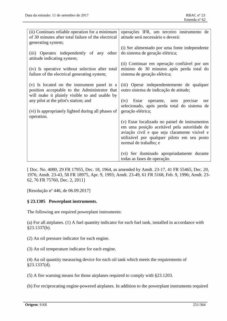
Data da emissão: 11 de setembro de 2017 RBAC nº 23
Emenda nº 62
Origem: SAR 251/364
(ii) Continues reliable operation for a minimum
of 30 minutes after total failure of the electrical
generating system;
(iii) Operates independently of any other
attitude indicating system;
(iv) Is operative without selection after total
failure of the electrical generating system;
(v) Is located on the instrument panel in a
position acceptable to the Administrator that
will make it plainly visible to and usable by
any pilot at the pilot's station; and
(vi) Is appropriately lighted during all phases of
operation.
operações IFR, um terceiro instrumento de
atitude será necessário e deverá:
(i) Ser alimentado por uma fonte independente
do sistema de geração elétrica;
(ii) Continuar em operação confiável por um
mínimo de 30 minutos após perda total do
sistema de geração elétrica;
(iii) Operar independentemente de qualquer
outro sistema de indicação de atitude;
(iv) Estar operante, sem precisar ser
selecionado, após perda total do sistema de
geração elétrica;
(v) Estar localizado no painel de instrumentos
em uma posição aceitável pela autoridade de
aviação civil e que seja claramente visível e
utilizável por qualquer piloto em seu posto
normal de trabalho; e
(vi) Ser iluminado apropriadamente durante
todas as fases de operação.
[ Doc. No. 4080, 29 FR 17955, Dec. 18, 1964, as amended by Amdt. 23-17, 41 FR 55465, Dec. 20,
1976; Amdt. 23-43, 58 FR 18975, Apr. 9, 1993; Amdt. 23-49, 61 FR 5168, Feb. 9, 1996; Amdt. 23-
62, 76 FR 75760, Dec. 2, 2011]
[Resolução nº 446, de 06.09.2017]
§ 23.1305 Powerplant instruments.
The following are required powerplant instruments:
(a) For all airplanes. (1) A fuel quantity indicator for each fuel tank, installed in accordance with
§23.1337(b).
(2) An oil pressure indicator for each engine.
(3) An oil temperature indicator for each engine.
(4) An oil quantity measuring device for each oil tank which meets the requirements of
§23.1337(d).
(5) A fire warning means for those airplanes required to comply with §23.1203.
(b) For reciprocating engine-powered airplanes. In addition to the powerplant instruments required

Data da emissão: 11 de setembro de 2017 RBAC nº 23
Emenda nº 62
Origem: SAR 252/364
by paragraph (a) of this section, the following powerplant instruments are required:
(1) An induction system air temperature indicator for each engine equipped with a preheater and
having induction air temperature limitations that can be exceeded with preheat.
(2) A tachometer indicator for each engine.
(3) A cylinder head temperature indicator for—
(i) Each air-cooled engine with cowl flaps;
(ii) [Reserved]
(iii) Each commuter category airplane.
(4) For each pump-fed engine, a means:
(i) That continuously indicates, to the pilot, the fuel pressure or fuel flow; or
(ii) That continuously monitors the fuel system and warns the pilot of any fuel flow trend that could
lead to engine failure.
(5) A manifold pressure indicator for each altitude engine and for each engine with a controllable
propeller.
(6) For each turbocharger installation:
(i) If limitations are established for either carburetor (or manifold) air inlet temperature or exhaust
gas or turbocharger turbine inlet temperature, indicators must be furnished for each temperature for
which the limitation is established unless it is shown that the limitation will not be exceeded in all
intended operations.
(ii) If its oil system is separate from the engine oil system, oil pressure and oil temperature
indicators must be provided.
(7) A coolant temperature indicator for each liquid-cooled engine.
(c) For turbine engine-powered airplanes. In addition to the powerplant instruments required by
paragraph (a) of this section, the following powerplant instruments are required:
(1) A gas temperature indicator for each engine.
(2) A fuel flowmeter indicator for each engine.
(3) A fuel low pressure warning means for each engine.
(4) A fuel low level warning means for any fuel tank that should not be depleted of fuel in normal
operations.
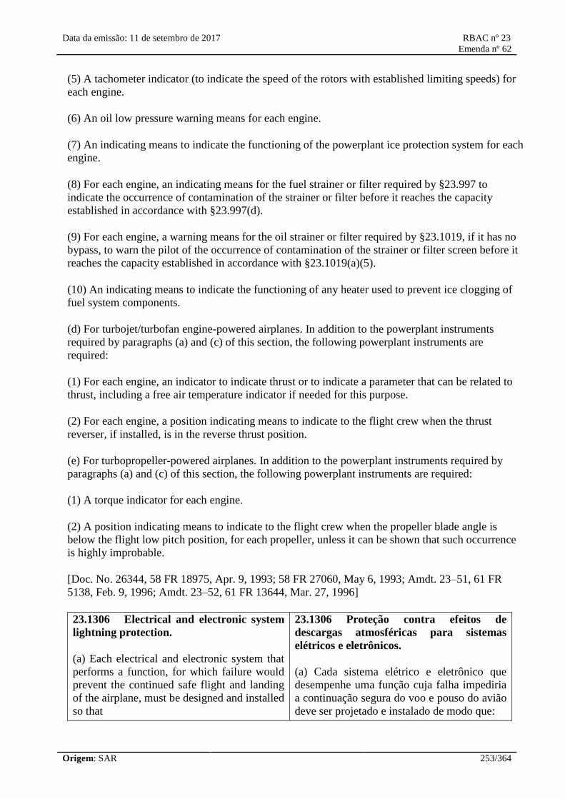
Data da emissão: 11 de setembro de 2017 RBAC nº 23
Emenda nº 62
Origem: SAR 253/364
(5) A tachometer indicator (to indicate the speed of the rotors with established limiting speeds) for
each engine.
(6) An oil low pressure warning means for each engine.
(7) An indicating means to indicate the functioning of the powerplant ice protection system for each
engine.
(8) For each engine, an indicating means for the fuel strainer or filter required by §23.997 to
indicate the occurrence of contamination of the strainer or filter before it reaches the capacity
established in accordance with §23.997(d).
(9) For each engine, a warning means for the oil strainer or filter required by §23.1019, if it has no
bypass, to warn the pilot of the occurrence of contamination of the strainer or filter screen before it
reaches the capacity established in accordance with §23.1019(a)(5).
(10) An indicating means to indicate the functioning of any heater used to prevent ice clogging of
fuel system components.
(d) For turbojet/turbofan engine-powered airplanes. In addition to the powerplant instruments
required by paragraphs (a) and (c) of this section, the following powerplant instruments are
required:
(1) For each engine, an indicator to indicate thrust or to indicate a parameter that can be related to
thrust, including a free air temperature indicator if needed for this purpose.
(2) For each engine, a position indicating means to indicate to the flight crew when the thrust
reverser, if installed, is in the reverse thrust position.
(e) For turbopropeller-powered airplanes. In addition to the powerplant instruments required by
paragraphs (a) and (c) of this section, the following powerplant instruments are required:
(1) A torque indicator for each engine.
(2) A position indicating means to indicate to the flight crew when the propeller blade angle is
below the flight low pitch position, for each propeller, unless it can be shown that such occurrence
is highly improbable.
[Doc. No. 26344, 58 FR 18975, Apr. 9, 1993; 58 FR 27060, May 6, 1993; Amdt. 23–51, 61 FR
5138, Feb. 9, 1996; Amdt. 23–52, 61 FR 13644, Mar. 27, 1996]
23.1306 Electrical and electronic system
lightning protection.
(a) Each electrical and electronic system that
performs a function, for which failure would
prevent the continued safe flight and landing
of the airplane, must be designed and installed
so that
23.1306 Proteção contra efeitos de
descargas atmosféricas para sistemas
elétricos e eletrônicos.
(a) Cada sistema elétrico e eletrônico que
desempenhe uma função cuja falha impediria
a continuação segura do voo e pouso do avião
deve ser projetado e instalado de modo que:

Data da emissão: 11 de setembro de 2017 RBAC nº 23
Emenda nº 62
Origem: SAR 254/364
(1) The function is not adversely affected
during and after the time the airplane is
exposed to lightning; and
(2) The system automatically recovers normal
operation of that function in a timely manner
after the airplane is exposed to lightning.
(b) For airplanes approved for instrument
flight rules operation, each electrical and
electronic system that performs a function, for
which failure would reduce the capability of
the airplane or the ability of the flightcrew to
respond to an adverse operating condition,
must be designed and installed so that the
function recovers normal operation in a
timely manner after the airplane is exposed to
lightning.
(1) A função não seja afetada adversamente
durante e após o período em que o avião é
exposto à descarga atmosférica; e
(2) O sistema automaticamente recupere a
operação normal daquela função em tempo
adequado após o avião ser exposto à descarga
atmosférica.
(b) Para aviões aprovados para operação de
acordo com as regras de voo por
instrumentos, cada sistema elétrico e
eletrônico que desempenhe uma função cuja
falha reduziria a capacidade do avião ou a
habilidade da tripulação de voo de reagir a
uma condição adversa de operação deve ser
projetado e instalado de modo que a função
recupere sua operação normal em tempo
adequado após o avião ser exposto à descarga
atmosférica.
[Doc. No. FAA–2010–0224; 76 FR 33135, June 8, 2011]
[Resolução nº 275, de 12 de junho de 2013, publicada no Diário Oficial da União n° 112, Seção 1,
p. 1-2, de 13/06/2013]
§ 23.1307 Miscellaneous equipment.
The equipment necessary for an airplane to operate at the maximum operating altitude and in the
kinds of operation and meteorological conditions for which certification is requested and is
approved in accordance with §23.1559 must be included in the type design.
[Doc. No. 4080, 29 FR 17955, Dec. 18, 1964; 30 FR 258, Jan. 9, 1965, as amended by Amdt. 23–
23, 43 FR 50593, Oct. 30, 1978; Amdt. 23–43, 58 FR 18976, Apr. 9, 1993; Amdt. 23–49, 61 FR
5168, Feb. 9, 1996]
§ 23.1308 High-intensity Radiated Fields (HIRF) Protection.
(a) Except as provided in paragraph (d) of this section, each electrical and electronic system that
performs a function whose failure would prevent the continued safe flight and landing of the
airplane must be designed and installed so that—
(1) The function is not adversely affected during and after the time the airplane is exposed to HIRF
environment I, as described in appendix J to this part;
(2) The system automatically recovers normal operation of that function, in a timely manner, after
the airplane is exposed to HIRF environment I, as described in appendix J to this part, unless the
system's recovery conflicts with other operational or functional requirements of the system; and

Data da emissão: 11 de setembro de 2017 RBAC nº 23
Emenda nº 62
Origem: SAR 255/364
(3) The system is not adversely affected during and after the time the airplane is exposed to HIRF
environment II, as described in appendix J to this part.
(b) Each electrical and electronic system that performs a function whose failure would significantly
reduce the capability of the airplane or the ability of the flightcrew to respond to an adverse
operating condition must be designed and installed so the system is not adversely affected when the
equipment providing the function is exposed to equipment HIRF test level 1 or 2, as described in
appendix J to this part.
(c) Each electrical and electronic system that performs a function whose failure would reduce the
capability of the airplane or the ability of the flightcrew to respond to an adverse operating
condition must be designed and installed so the system is not adversely affected when the
equipment providing the function is exposed to equipment HIRF test level 3, as described in
appendix J to this part.
(d) Before December 1, 2012, an electrical or electronic system that performs a function whose
failure would prevent the continued safe flight and landing of an airplane may be designed and
installed without meeting the provisions of paragraph (a) provided—
(1) The system has previously been shown to comply with special conditions for HIRF, prescribed
under §21.16, issued before December 1, 2007;
(2) The HIRF immunity characteristics of the system have not changed since compliance with the
special conditions was demonstrated; and
(3) The data used to demonstrate compliance with the special conditions is provided.
[Doc. No. FAA–2006–23657, 72 FR 44024, Aug. 6, 2007]
23.1309 Equipment, systems, and
installations.
The requirements of this section, except as
identified in paragraphs (a) through (d), are
applicable, in addition to specific design
requirements of RBAC 23, to any equipment or
system as installed in the airplane. This section
is a regulation of general requirements and
does not supersede any requirements contained
in another section of RBAC 23.
(a) The airplane equipment and systems must
be designed and installed so that:
(1) Those required for type certification or by
operating rules perform as intended under the
airplane operating and environmental
conditions, including the indirect effects of
23.1309 Equipamentos, sistemas e
instalações.
Os requisitos desta seção, exceto conforme
identificado nos parágrafos de (a) a (d), são
aplicáveis, adicionalmente a requisitos
específicos de projeto do RBAC 23, a qualquer
equipamento ou sistema instalado no avião.
Esta seção é um regulamento de requisitos
gerais e não substitui qualquer requisito
presente em outra seção do RBAC 23.
(a) Os equipamentos e sistemas do avião
devem ser projetados e instalados de modo que:
(1) Aqueles requeridos para a certificação de
tipo ou por regras operacionais funcionem
conforme pretendido sob as condições
operacionais e ambientais do avião, incluindo

Data da emissão: 11 de setembro de 2017 RBAC nº 23
Emenda nº 62
Origem: SAR 256/364
lightning strikes.
(2) Any equipment and system does not
adversely affect the safety of the airplane or its
occupants, or the proper functioning of those
covered by paragraph (a)(1) of this section.
(b) Minor, major, hazardous, or catastrophic
failure condition(s), which occur during Type
Inspection Authorization or ANAC flight-
certification testing, must have root cause
analysis and corrective action.
(c) The airplane systems and associated
components considered separately and in
relation to other systems, must be designed and
installed so that:
(1) Each catastrophic failure condition is
extremely improbable and does not result from
a single failure;
(2) Each hazardous failure condition is
extremely remote; and
(3) Each major failure condition is remote.
(d) Information concerning an unsafe system
operating condition must be provided in a
timely manner to the crew to enable them to
take appropriate corrective action. An
appropriate alert must be provided if immediate
pilot awareness and immediate or subsequent
corrective action is required. Systems and
controls, including indications and
annunciations, must be designed to minimize
crew errors which could create additional
hazards.
os efeitos indiretos de impactos por raios.
(2) Qualquer equipamento e sistema não afete
adversamente a segurança operacional do avião
ou de seus ocupantes, ou o funcionamento
adequado daqueles cobertos pelo parágrafo
(a)(1) desta seção.
(b) Condições de falha minor, major, hazardous
ou catastróficas que ocorram durante a
Autorização de Inspeção de Tipo ou ensaio de
certificação em voo da ANAC devem ser
submetidas a análise de causa raiz e possuir
ação corretiva.
(c) Os sistemas do avião e componentes
associados, considerados separadamente ou em
relação a outros sistemas, devem ser projetados
e instalados de modo que:
(1) Cada condição de falha catastrófica seja
extremamente improvável e não seja resultante
de uma falha simples;
(2) Cada condição de falha hazardous seja
extremamente remota; e
(3) Cada condição de falha major seja remota.
(d) Informações referentes a condições
inseguras de operação dos sistemas devem ser
fornecidas em tempo hábil à tripulação de
modo a lhes permitir tomar as ações corretivas
adequadas. Deve ser fornecido um alerta
apropriado caso sejam necessários o
reconhecimento imediato e a ação corretiva
imediata ou subsequente. Sistemas e comandos,
inclusive indicações e anúncios, devem ser
projetados de modo a minimizar erros da
tripulação que possam gerar perigos adicionais.
[Doc. No. FAA-2009-0738, 76 FR 75760, Dec. 2, 2011]
[Resolução nº 446, de 06.09.2017]
23.1310 Power source capacity and
distribution.
(a) Each installation whose functioning is
23.1310 Capacidade das fontes de energia e
do sistema de distribuição.
(a) Cada instalação cujo funcionamento é

Data da emissão: 11 de setembro de 2017 RBAC nº 23
Emenda nº 62
Origem: SAR 257/364
required for type certification or under
operating rules and that requires a power
supply is an "essential load" on the power
supply. The power sources and the system must
be able to supply the following power loads in
probable operating combinations and for
probable durations:
(1) Loads connected to the system with the
system functioning normally.
(2) Essential loads, after failure of any one
prime mover, power converter, or energy
storage device.
(3) Essential loads after failure of--
(i) Any one engine on two-engine airplanes;
and
(ii) Any two engines on airplanes with three or
more engines.
(4) Essential loads for which an alternate
source of power is required, after any failure or
malfunction in any one power supply system,
distribution system, or other utilization system.
(b) In determining compliance with paragraphs
(a)(2) and (3) of this section, the power loads
may be assumed to be reduced under a
monitoring procedure consistent with safety in
the kinds of operation authorized. Loads not
required in controlled flight need not be
considered for the two-engine-inoperative
condition on airplanes with three or more
engines.
requerido para certificação de tipo ou por
regras de operação e que requeira um
fornecimento de energia é uma “carga
essencial” do fornecimento de energia. As
fontes de energia e o sistema devem ser
capazes de fornecer as seguintes cargas nas
combinações operacionais prováveis e pelas
durações prováveis:
(1) Cargas conectadas ao sistema com o
sistema funcionando normalmente.
(2) Cargas essenciais, após a falha de qualquer
fonte primária, conversor de energia ou
equipamento de acúmulo de energia.
(3) Cargas essenciais após a falha de:
(i) Qualquer motor em aviões com dois
motores; e
(ii) Quaisquer dois motores em aviões com três
ou mais motores.
(4) Cargas essenciais para as quais uma fonte
de energia alternativa é requerida, após
qualquer falha ou mau funcionamento em
qualquer sistema de alimentação de energia,
sistema de distribuição, ou outro sistema de
utilização.
(b) Na determinação de cumprimento com os
parágrafos (a)(2) e (3) desta seção, as cargas
podem ser aceitas de serem reduzidas em um
procedimento de monitoramento consistente
com a segurança nos tipos de operação
autorizada. Cargas não requeridas em voo
controlado não precisam ser consideradas para
a condição de dois motores inoperantes em
aviões com três ou mais motores.
[Doc. No. FAA-2009-0738, 76 FR 75760, Dec. 2, 2011]
[Resolução nº 446, de 06.09.2017]
Instruments: Installation
23.1311 Electronic display instrument
systems.
23.1311 Sistemas de instrumentos com
display eletrônico.

Data da emissão: 11 de setembro de 2017 RBAC nº 23
Emenda nº 62
Origem: SAR 258/364
(a) Electronic display indicators, including
those with features that make isolation and
independence between powerplant instrument
systems impractical, must:
(1) Meet the arrangement and visibility
requirements of section 23.1321 of this RBAC.
(2) Be easily legible under all lighting
conditions encountered in the cockpit,
including direct sunlight, considering the
expected electronic display brightness level at
the end of an electronic display indictor's
useful life. Specific limitations on display
system useful life must be contained in the
Instructions for Continued Airworthiness
required by section 23.1529 of this RBAC.
(3) Not inhibit the primary display of attitude,
airspeed, altitude, or powerplant parameters
needed by any pilot to set power within
established limitations, in any normal mode of
operation.
(4) Not inhibit the primary display of engine
parameters needed by any pilot to properly set
or monitor powerplant limitations during the
engine starting mode of operation.
(5) For certification for Instrument Flight Rules
(IFR) operations, have an independent
magnetic direction indicator and either an
independent secondary mechanical altimeter,
airspeed indicator, and attitude instrument or an
electronic display parameters for the altitude,
airspeed, and attitude that are independent from
the airplane's primary electrical power system.
These secondary instruments may be installed
in panel positions that are displaced from the
primary positions specified by paragraph
23.1321(d) of this RBAC, but must be located
where they meet the pilot's visibility
requirements of paragraph 23.1321(a) of this
RBAC.
(6) Incorporate sensory cues that provide a
quick glance sense of rate and, where
appropriate, trend information to the parameter
(a) Indicadores em display eletrônico,
incluindo aqueles com aspectos que fazem
isolamento e independência entre instrumentos
do grupo motopropulsor impraticáveis, devem:
(1) Atender aos requisitos de arranjo e
visibilidade da seção 23.1321 deste RBAC.
(2) Ser facilmente legível sob todas as
condições de iluminação encontradas na cabine
de comando, incluindo raios solares diretos,
considerando o nível de brilho esperado para o
display eletrônico no final de sua vida útil.
Limitações específicas na vida útil do display
eletrônico devem estar contidas nas instruções
de aeronavegabilidade continuada requeridas
pela seção 23.1529 deste RBAC.
(3) Não inibir a indicação primária de atitude,
velocidade no ar, altitude ou parâmetros do
grupo motopropulsor necessária a qualquer
piloto para ajustar a potência dentro das
limitações estabelecidas, em qualquer modo
normal de operação.
(4) Não inibir a indicação primária de
parâmetros de motor necessária a qualquer
piloto para ajustar ou monitorar adequadamente
limitações do grupo motopropulsor durante o
modo de operação de partida do motor.
(5) Para certificação para operações seguindo
Regras do Voo por Instrumentos (IFR), ter um
indicador de direção magnética independente e
ou um altímetro, um indicador de velocidade
no ar e um instrumento de atitude mecânicos
secundários independentes ou um display
eletrônico para os parâmetros de altitude,
velocidade no ar e atitude que sejam
independentes do sistema de energia elétrica
primário do avião. Esses instrumentos
secundários podem ser instalados em posições
no painel que sejam deslocadas das posições
primárias especificadas pelo parágrafo
23.1321(d) deste RBAC, mas devem estar
localizados onde cumpram com os requisitos
de visibilidade dos pilotos do parágrafo
23.1321(a) deste RBAC.
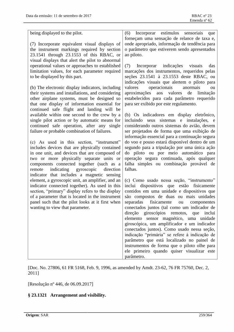
Data da emissão: 11 de setembro de 2017 RBAC nº 23
Emenda nº 62
Origem: SAR 259/364
being displayed to the pilot.
(7) Incorporate equivalent visual displays of
the instrument markings required by section
23.1541 through 23.1553 of this RBAC, or
visual displays that alert the pilot to abnormal
operational values or approaches to established
limitation values, for each parameter required
to be displayed by this part.
(b) The electronic display indicators, including
their systems and installations, and considering
other airplane systems, must be designed so
that one display of information essential for
continued safe flight and landing will be
available within one second to the crew by a
single pilot action or by automatic means for
continued safe operation, after any single
failure or probable combination of failures.
(c) As used in this section, “instrument”
includes devices that are physically contained
in one unit, and devices that are composed of
two or more physically separate units or
components connected together (such as a
remote indicating gyroscopic direction
indicator that includes a magnetic sensing
element, a gyroscopic unit, an amplifier, and an
indicator connected together). As used in this
section, “primary” display refers to the display
of a parameter that is located in the instrument
panel such that the pilot looks at it first when
wanting to view that parameter.
(6) Incorporar estímulos sensoriais que
forneçam uma sensação de relance de taxa e,
onde apropriado, informação de tendência para
o parâmetro que estiverem sendo apresentados
ao piloto.
(7) Incorporar indicações visuais das
marcações dos instrumentos, requeridos pelas
seções 23.1541 à 23.1553 deste RBAC, ou
indicações visuais que alertem o piloto para
valores operacionais anormais ou
aproximações aos valores de limitação
estabelecidos para cada parâmetro requerido
para ser exibido por este regulamento.
(b) Os indicadores em display eletrônico,
incluindo seus sistemas e instalações, e
considerando outros sistemas do avião, devem
ser projetados de forma que uma exibição de
informação essencial para a continuação segura
do voo e pouso estará disponível dentro de um
segundo para a tripulação por uma única ação
do piloto ou por meio automático para
operação segura continuada, após qualquer
falha simples ou combinação provável de
falhas.
(c) Como usado nessa seção, “instrumento”
inclui dispositivos que estão fisicamente
contidos em uma unidade e dispositivos que
são compostos de duas ou mais unidades
separadas fisicamente ou componentes
conectados juntos (tal como um indicador de
direção giroscópios remotos, que inclui
elemento sensor magnético, uma unidade
giroscópica, um amplificador e um indicador
conectados juntos). Como usado nessa seção,
indicação “primária” se refere à indicação de
parâmetro que está localizado no painel de
instrumentos de forma que o piloto olhe para
ele primeiro quando quiser visualizar este
parâmetro.
[Doc. No. 27806, 61 FR 5168, Feb. 9, 1996, as amended by Amdt. 23-62, 76 FR 75760, Dec. 2,
2011]
[Resolução nº 446, de 06.09.2017]
§ 23.1321 Arrangement and visibility.

Data da emissão: 11 de setembro de 2017 RBAC nº 23
Emenda nº 62
Origem: SAR 260/364
(a) Each flight, navigation, and powerplant instrument for use by any required pilot during takeoff,
initial climb, final approach, and landing must be located so that any pilot seated at the controls can
monitor the airplane's flight path and these instruments with minimum head and eye movement. The
powerplant instruments for these flight conditions are those needed to set power within powerplant
limitations.
(b) For each multiengine airplane, identical powerplant instruments must be located so as to prevent
confusion as to which engine each instrument relates.
(c) Instrument panel vibration may not damage, or impair the accuracy of, any instrument.
(d) For each airplane, the flight instruments required by §23.1303, and, as applicable, by the
operating rules of this chapter, must be grouped on the instrument panel and centered as nearly as
practicable about the vertical plane of each required pilot's forward vision. In addition:
(1) The instrument that most effectively indicates the attitude must be on the panel in the top center
position;
(2) The instrument that most effectively indicates airspeed must be adjacent to and directly to the
left of the instrument in the top center position;
(3) The instrument that most effectively indicates altitude must be adjacent to and directly to the
right of the instrument in the top center position;
(4) The instrument that most effectively indicates direction of flight, other than the magnetic
direction indicator required by §23.1303(c), must be adjacent to and directly below the instrument
in the top center position; and
(5) Electronic display indicators may be used for compliance with paragraphs (d)(1) through (d)(4)
of this section when such displays comply with requirements in §23.1311.
(e) If a visual indicator is provided to indicate malfunction of an instrument, it must be effective
under all probable cockpit lighting conditions.
[Doc. No. 4080, 29 FR 17955, Dec. 18, 1964, as amended by Amdt. 23–14, 38 FR 31824, Nov. 19,
1973; Amdt. 23–20, 42 FR 36968, July 18, 1977; Amdt. 23–41, 55 FR 43310, Oct. 26, 1990; 55 FR
46888, Nov. 7, 1990; Amdt. 23–49, 61 FR 5168, Feb. 9, 1996]
§ 23.1322 Warning, caution, and advisory lights.
If warning, caution, or advisory lights are installed in the cockpit, they must, unless otherwise
approved by the Administrator, be—
(a) Red, for warning lights (lights indicating a hazard which may require immediate corrective
action);
(b) Amber, for caution lights (lights indicating the possible need for future corrective action);
(c) Green, for safe operation lights; and

Data da emissão: 11 de setembro de 2017 RBAC nº 23
Emenda nº 62
Origem: SAR 261/364
(d) Any other color, including white, for lights not described in paragraphs (a) through (c) of this
section, provided the color differs sufficiently from the colors prescribed in paragraphs (a) through
(c) of this section to avoid possible confusion.
(e) Effective under all probable cockpit lighting conditions.
[Amdt. 23–17, 41 FR 55465, Dec. 20, 1976, as amended by Amdt. 23–43, 58 FR 18976, Apr. 9,
1993]
23.1323 Airspeed indicating system.
(a) Each airspeed indicating instrument must be
calibrated to indicate true airspeed (at sea level
with a standard atmosphere) with a minimum
practicable instrument calibration error when
the corresponding pitot and static pressures are
applied.
(b) Each airspeed system must be calibrated in
flight to determine the system error. The
system error, including position error, but
excluding the airspeed indicator instrument
calibration error, may not exceed three percent
of the calibrated airspeed or five knots (9,25
km/h), whichever is greater, throughout the
following speed ranges:
(1) 1,3 VS1 to VMO/MMO or VNE, whichever is
appropriate with flaps retracted.
(2) 1.3 VS1 to VFE with flaps extended.
(c) The design and installation of each airspeed
indicating system must provide positive
drainage of moisture from the pitot static
plumbing.
(d) If certification for instrument flight rules or
flight in icing conditions is requested, each
airspeed system must have a heated pitot tube
or an equivalent means of preventing
malfunction due to icing.
(e) In addition, for normal, utility, and
acrobatic category multiengine jets of more
than 6.000 pounds (2.722 kg) maximum weight
and commuter category airplanes, each system
must be calibrated to determine the system
error during the accelerate-takeoff ground run.
23.1323 Airspeed indicating system.
(a) Cada instrumento de indicação de
velocidade no ar deve ser calibrado de modo a
indicar a velocidade verdadeira (ao nível do
mar, em atmosfera padrão) com o mínimo erro
de calibração atingível quando forem aplicadas
as pressões correspondentes no(s) tubo(s) de
pitot e tomada(s) de pressão estática.
(b) Cada sistema de velocidade no ar deve ser
calibrado em voo de modo que seja
determinado o erro do sistema. O erro do
sistema, incluindo o erro de posição, porém
desconsiderando o erro de calibração do
instrumento de indicação de velocidade no ar,
não pode exceder 3% da velocidade calibrada
ou 5 kt (9,25 km/h), o que for maior, ao longo
das seguintes faixas de velocidades:
(1) De 1,3 vezes a VS1 até a VMO/MMO ou VNE,
a que for apropriada, com flapes recolhidos.
(2) De 1,3 vezes a VS1 até a VFE com flapes
estendidos.
(c) O projeto e a instalação de cada sistema de
indicação de velocidade no ar devem permitir a
drenagem eficaz da umidade da tubulação do
sistema pitot/estático.
(d) Caso seja solicitada certificação para voo
IFR ou voo em condições de formação de gelo,
cada sistema de velocidade no ar deve ter um
tubo de pitot aquecido ou uma forma
equivalente de evitar o mau funcionamento
decorrente da formação de gelo.
(e) Adicionalmente, para aviões a jato
multimotores de mais de 6.000 libras (2.722
Data da emissão: 11 de setembro de 2017 RBAC nº 23
Emenda nº 62
Origem: SAR 262/364
The ground run calibration must be
determined:
(1) From 0,8 of the minimum value of V1 to the
maximum value of V2, considering the
approved ranges of altitude and weight; and
(2) The ground run calibration must be
determined assuming an engine failure at the
minimum value of V1.
(f) For commuter category airplanes, where
duplicate airspeed indicators are required, their
respective pitot tubes must be far enough apart
to avoid damage to both tubes in a collision
with a bird.
kg) de peso máximo, das categorias normal,
utilidade e acrobática e aviões da categoria
transporte regional, cada sistema deve ser
calibrado de modo a determinar o erro do
sistema durante a corrida de decolagem
acelerada em solo. A calibração para corrida
em solo deve ser determinada:
(1) De 0,8 vezes o valor mínimo de V1 até o
valor máximo de V2, considerando os valores
aprovados para altitude e peso; e
(2) A calibração para corrida em solo deve ser
obtida assumindo uma falha de motor no valor
mínimo de V1.
(f) Para aviões da categoria transporte regional,
onde for requerida a duplicação do indicador de
velocidade no ar, os respectivos tubos de pitot
devem estar distantes um do outro o suficiente
para evitar danos a ambos os tubos quando da
colisão com um pássaro.
[Amdt. 23-20, 42 FR 36968, July 18, 1977, as amended by Amdt. 23-34, 52 FR 1834, Jan. 15,
1987; 52 FR 34745, Sept. 14, 1987; Amdt. 23-42, 56 FR 354, Jan. 3, 1991; Amdt. 23-49, 61 FR
5168, Feb. 9, 1996; Amdt. 23-62, 76 FR 75761, Dec. 2, 2011]
[Resolução nº 446, de 06.09.2017]
§ 23.1325 Static pressure system.
(a) Each instrument provided with static pressure case connections must be so vented that the
influence of airplane speed, the opening and closing of windows, airflow variations, moisture, or
other foreign matter will least affect the accuracy of the instruments except as noted in paragraph
(b)(3) of this section.
(b) If a static pressure system is necessary for the functioning of instruments, systems, or devices, it
must comply with the provisions of paragraphs (b)(1) through (3) of this section.
(1) The design and installation of a static pressure system must be such that—
(i) Positive drainage of moisture is provided;
(ii) Chafing of the tubing, and excessive distortion or restriction at bends in the tubing, is avoided;
and
(iii) The materials used are durable, suitable for the purpose intended, and protected against
corrosion.

Data da emissão: 11 de setembro de 2017 RBAC nº 23
Emenda nº 62
Origem: SAR 263/364
(2) A proof test must be conducted to demonstrate the integrity of the static pressure system in the
following manner:
(i) Unpressurized airplanes. Evacuate the static pressure system to a pressure differential of
approximately 1 inch of mercury or to a reading on the altimeter, 1,000 feet above the aircraft
elevation at the time of the test. Without additional pumping for a period of 1 minute, the loss of
indicated altitude must not exceed 100 feet on the altimeter.
(ii) Pressurized airplanes. Evacuate the static pressure system until a pressure differential equivalent
to the maximum cabin pressure differential for which the airplane is type certificated is achieved.
Without additional pumping for a period of 1 minute, the loss of indicated altitude must not exceed
2 percent of the equivalent altitude of the maximum cabin differential pressure or 100 feet,
whichever is greater.
(3) If a static pressure system is provided for any instrument, device, or system required by the
operating rules of this chapter, each static pressure port must be designed or located in such a
manner that the correlation between air pressure in the static pressure system and true ambient
atmospheric static pressure is not altered when the airplane encounters icing conditions. An
antiicing means or an alternate source of static pressure may be used in showing compliance with
this requirement. If the reading of the altimeter, when on the alternate static pressure system differs
from the reading of the altimeter when on the primary static system by more than 50 feet, a
correction card must be provided for the alternate static system.
(c) Except as provided in paragraph (d) of this section, if the static pressure system incorporates
both a primary and an alternate static pressure source, the means for selecting one or the other
source must be designed so that—
(1) When either source is selected, the other is blocked off; and
(2) Both sources cannot be blocked off simultaneously.
(d) For unpressurized airplanes, paragraph (c)(1) of this section does not apply if it can be
demonstrated that the static pressure system calibration, when either static pressure source is
selected, is not changed by the other static pressure source being open or blocked.
(e) Each static pressure system must be calibrated in flight to determine the system error. The
system error, in indicated pressure altitude, at sea-level, with a standard atmosphere, excluding
instrument calibration error, may not exceed ±30 feet per 100 knot speed for the appropriate
configuration in the speed range between 1.3 VS0with flaps extended, and 1.8 VS1with flaps
retracted. However, the error need not be less than 30 feet.
(f) [Reserved]
(g) For airplanes prohibited from flight in instrument meteorological or icing conditions, in
accordance with §23.1559(b) of this part, paragraph (b)(3) of this section does not apply.
[Amdt. 23–1, 30 FR 8261, June 29, 1965, as amended by Amdt. 23–6, 32 FR 7586, May 24, 1967;
32 FR 13505, Sept. 27, 1967; 32 FR 13714, Sept. 30, 1967; Amdt. 23–20, 42 FR 36968, July 18,
1977; Amdt. 23–34, 52 FR 1834, Jan. 15, 1987; Amdt. 23–42, 56 FR 354, Jan. 3, 1991; Amdt. 23–
Data da emissão: 11 de setembro de 2017 RBAC nº 23
Emenda nº 62
Origem: SAR 264/364
49, 61 FR 5169, Feb. 9, 1996; Amdt. 23–50, 61 FR 5192, Feb. 9, 1996]
§ 23.1326 Pitot heat indication systems.
If a flight instrument pitot heating system is installed to meet the requirements specified in
§23.1323(d), an indication system must be provided to indicate to the flight crew when that pitot
heating system is not operating. The indication system must comply with the following
requirements:
(a) The indication provided must incorporate an amber light that is in clear view of a flightcrew
member.
(b) The indication provided must be designed to alert the flight crew if either of the following
conditions exist:
(1) The pitot heating system is switched “off.”
(2) The pitot heating system is switched “on” and any pitot tube heating element is inoperative.
[Doc. No. 27806, 61 FR 5169, Feb. 9, 1996]
§ 23.1327 Magnetic direction indicator.
(a) Except as provided in paragraph (b) of this section—
(1) Each magnetic direction indicator must be installed so that its accuracy is not excessively
affected by the airplane's vibration or magnetic fields; and
(2) The compensated installation may not have a deviation in level flight, greater than ten degrees
on any heading.
(b) A magnetic nonstabilized direction indicator may deviate more than ten degrees due to the
operation of electrically powered systems such as electrically heated windshields if either a
magnetic stabilized direction indicator, which does not have a deviation in level flight greater than
ten degrees on any heading, or a gyroscopic direction indicator, is installed. Deviations of a
magnetic nonstabilized direction indicator of more than 10 degrees must be placarded in accordance
with §23.1547(e).
[Amdt. 23–20, 42 FR 36969, July 18, 1977]
§ 23.1329 Automatic pilot system.
If an automatic pilot system is installed, it must meet the following:
(a) Each system must be designed so that the automatic pilot can—
(1) Be quickly and positively disengaged by the pilots to prevent it from interfering with their
control of the airplane; or

Data da emissão: 11 de setembro de 2017 RBAC nº 23
Emenda nº 62
Origem: SAR 265/364
(2) Be sufficiently overpowered by one pilot to let him control the airplane.
(b) If the provisions of paragraph (a)(1) of this section are applied, the quick release (emergency)
control must be located on the control wheel (both control wheels if the airplane can be operated
from either pilot seat) on the side opposite the throttles, or on the stick control, (both stick controls,
if the airplane can be operated from either pilot seat) such that it can be operated without moving
the hand from its normal position on the control.
(c) Unless there is automatic synchronization, each system must have a means to readily indicate to
the pilot the alignment of the actuating device in relation to the control system it operates.
(d) Each manually operated control for the system operation must be readily accessible to the pilot.
Each control must operate in the same plane and sense of motion as specified in §23.779 for cockpit
controls. The direction of motion must be plainly indicated on or near each control.
(e) Each system must be designed and adjusted so that, within the range of adjustment available to
the pilot, it cannot produce hazardous loads on the airplane or create hazardous deviations in the
flight path, under any flight condition appropriate to its use, either during normal operation or in the
event of a malfunction, assuming that corrective action begins within a reasonable period of time.
(f) Each system must be designed so that a single malfunction will not produce a hardover signal in
more than one control axis. If the automatic pilot integrates signals from auxiliary controls or
furnishes signals for operation of other equipment, positive interlocks and sequencing of
engagement to prevent improper operation are required.
(g) There must be protection against adverse interaction of integrated components, resulting from a
malfunction.
(h) If the automatic pilot system can be coupled to airborne navigation equipment, means must be
provided to indicate to the flight crew the current mode of operation. Selector switch position is not
acceptable as a means of indication.
[Doc. No. 4080, 29 FR 17955, Dec. 18, 1964; 30 FR 258, Jan. 9, 1965, as amended by Amdt. 23–
23, 43 FR 50593, Oct. 30, 1978; Amdt. 23–43, 58 FR 18976, Apr. 9, 1993; Amdt. 23–49, 61 FR
5169, Feb. 9, 1996]
23.1331 Instruments using a power source.
For each instrument that uses a power source,
the following apply:
(a) Each instrument must have an integral
visual power annunciator or separate power
indicator to indicate when power is not
adequate to sustain proper instrument
performance. If a separate indicator is used, it
must be located so that the pilot using the
instruments can monitor the indicator with
minimum head and eye movement. The power
23.1331 Instrumentos utilizando uma fonte
de energia.
Para cada instrumento que use uma fonte de
energia, o seguinte se aplica:
(a) Cada instrumento deve ter um anunciador
visual de energia integrado ou indicador de
energia para indicar quando a energia não é
adequada para manter o desempenho adequado
do instrumento. Se um indicador separado é
usado, deve ser localizado de maneira que o
piloto usando os instrumentos possa monitorar

Data da emissão: 11 de setembro de 2017 RBAC nº 23
Emenda nº 62
Origem: SAR 266/364
must be sensed at or near the point where it
enters the instrument. For electric and
vacuum/pressure instruments, the power is
considered to be adequate when the voltage or
the vacuum/pressure, respectively, is within
approved limits.
(b) The installation and power supply systems
must be designed so that:
(1) The failure of one instrument will not
interfere with the proper supply of energy to
the remaining instrument; and
(2) The failure of the energy supply from one
source will not interfere with the proper supply
of energy from any other source.
(c) For certification for Instrument Flight Rules
(IFR) operations and for the heading, altitude,
airspeed, and attitude, there must be at least:
(1) Two independent sources of power (not
driven by the same engine on multiengine
airplanes), and a manual or an automatic means
to select each power source; or
(2) A separate display of parameters for
heading, altitude, airspeed, and attitude that has
a power source independent from the airplane’s
primary electrical power system.
o indicador com mínimo de movimento de
cabeça e olhos. A energia deve ser medida no
ou próximo ao ponto em que ela entra no
instrumento. Para instrumentos elétricos e de
pressão/vácuo, a energia é considerada
adequada quando a tensão ou vácuo/pressão,
respectivamente, está dentro dos limites
aprovados.
(b) A instalação e os sistemas de fornecimento
de energia devem ser projetados para que:
(1) A falha de um instrumento não interferirá
no adequado fornecimento de energia ao
instrumento remanescente; e
(2) A falha de fornecimento de energia de uma
fonte não interferirá no adequado fornecimento
de energia de qualquer outra fonte.
(c) Para certificação para operação de acordo
com as regras de voo por instrumentos e para a
proa, altitude, velocidade do ar e atitude, deve
haver ao menos:
(1) Duas fontes independentes de energia (não
movidas pelo mesmo motor em aviões
multimotores) e um meio manual ou
automático de selecionar cada fonte de energia;
ou
(2) Um display de parâmetros separado para
proa, altitude, velocidade do ar e atitude que
tenha uma fonte de energia independente do
sistema de energia elétrica primário do avião.
[Doc. No. 26344, 58 FR 18976, Apr. 9, 1993, as amended by Amdt. 23-62, 76 FR 75761, Dec. 2,
2011]
[Resolução nº 446, de 06.09.2017]
§ 23.1335 Flight director systems.
If a flight director system is installed, means must be provided to indicate to the flight crew its
current mode of operation. Selector switch position is not acceptable as a means of indication.
[Amdt. 23–20, 42 FR 36969, July 18, 1977]
§ 23.1337 Powerplant instruments installation.

Data da emissão: 11 de setembro de 2017 RBAC nº 23
Emenda nº 62
Origem: SAR 267/364
(a) Instruments and instrument lines. (1) Each powerplant and auxiliary power unit instrument line
must meet the requirements of §23.993.
(2) Each line carrying flammable fluids under pressure must—
(i) Have restricting orifices or other safety devices at the source of pressure to prevent the escape of
excessive fluid if the line fails; and
(ii) Be installed and located so that the escape of fluids would not create a hazard.
(3) Each powerplant and auxiliary power unit instrument that utilizes flammable fluids must be
installed and located so that the escape of fluid would not create a hazard.
(b) Fuel quantity indication. There must be a means to indicate to the flightcrew members the
quantity of usable fuel in each tank during flight. An indicator calibrated in appropriate units and
clearly marked to indicate those units must be used. In addition:
(1) Each fuel quantity indicator must be calibrated to read “zero” during level flight when the
quantity of fuel remaining in the tank is equal to the unusable fuel supply determined under
§23.959(a);
(2) Each exposed sight gauge used as a fuel quantity indicator must be protected against damage;
(3) Each sight gauge that forms a trap in which water can collect and freeze must have means to
allow drainage on the ground;
(4) There must be a means to indicate the amount of usable fuel in each tank when the airplane is on
the ground (such as by a stick gauge);
(5) Tanks with interconnected outlets and airspaces may be considered as one tank and need not
have separate indicators; and
(6) No fuel quantity indicator is required for an auxiliary tank that is used only to transfer fuel to
other tanks if the relative size of the tank, the rate of fuel transfer, and operating instructions are
adequate to—
(i) Guard against overflow; and
(ii) Give the flight crewmembers prompt warning if transfer is not proceeding as planned.
(c) Fuel flowmeter system. If a fuel flowmeter system is installed, each metering component must
have a means to by-pass the fuel supply if malfunctioning of that component severely restricts fuel
flow.
(d) Oil quantity indicator. There must be a means to indicate the quantity of oil in each tank—
(1) On the ground (such as by a stick gauge); and
Data da emissão: 11 de setembro de 2017 RBAC nº 23
Emenda nº 62
Origem: SAR 268/364
(2) In flight, to the flight crew members, if there is an oil transfer system or a reserve oil supply
system.
[Doc. No. 4080, 29 FR 17955, Dec. 18, 1964, as amended by Amdt. 23–7, 34 FR 13096, Aug. 13,
1969; Amdt. 23–18, 42 FR 15042, Mar. 17, 1977; Amdt. 23–43, 58 FR 18976, Apr. 9, 1993; Amdt.
23–51, 61 FR 5138, Feb. 9, 1996; Amdt. 23–49, 61 FR 5169, Feb. 9, 1996]
Electrical Systems and Equipment
§ 23.1351 General.
(a) Electrical system capacity. Each electrical system must be adequate for the intended use. In
addition—
(1) Electric power sources, their transmission cables, and their associated control and protective
devices, must be able to furnish the required power at the proper voltage to each load circuit
essential for safe operation; and
(2) Compliance with paragraph (a)(1) of this section must be shown as follows—
(i) For normal, utility, and acrobatic category airplanes, by an electrical load analysis or by
electrical measurements that account for the electrical loads applied to the electrical system in
probable combinations and for probable durations; and
(ii) For commuter category airplanes, by an electrical load analysis that accounts for the electrical
loads applied to the electrical system in probable combinations and for probable durations.
(b) Function. For each electrical system, the following apply:
(1) Each system, when installed, must be—
(i) Free from hazards in itself, in its method of operation, and in its effects on other parts of the
airplane;
(ii) Protected from fuel, oil, water, other detrimental substances, and mechanical damage; and
(iii) So designed that the risk of electrical shock to crew, passengers, and ground personnel is
reduced to a minimum.
(2) Electric power sources must function properly when connected in combination or
independently.
(3) No failure or malfunction of any electric power source may impair the ability of any remaining
source to supply load circuits essential for safe operation.
(4) In addition, for commuter category airplanes, the following apply:
(i) Each system must be designed so that essential load circuits can be supplied in the event of
reasonably probable faults or open circuits including faults in heavy current carrying cables;
Data da emissão: 11 de setembro de 2017 RBAC nº 23
Emenda nº 62
Origem: SAR 269/364
(ii) A means must be accessible in flight to the flight crewmembers for the individual and collective
disconnection of the electrical power sources from the system;
(iii) The system must be designed so that voltage and frequency, if applicable, at the terminals of all
essential load equipment can be maintained within the limits for which the equipment is designed
during any probable operating conditions;
(iv) If two independent sources of electrical power for particular equipment or systems are required,
their electrical energy supply must be ensured by means such as duplicate electrical equipment,
throwover switching, or multichannel or loop circuits separately routed; and
(v) For the purpose of complying with paragraph (b)(5) of this section, the distribution system
includes the distribution busses, their associated feeders, and each control and protective device.
(c) Generating system. There must be at least one generator/alternator if the electrical system
supplies power to load circuits essential for safe operation. In addition—
(1) Each generator/alternator must be able to deliver its continuous rated power, or such power as is
limited by its regulation system.
(2) Generator/alternator voltage control equipment must be able to dependably regulate the
generator/alternator output within rated limits.
(3) Automatic means must be provided to prevent damage to any generator/alternator and adverse
effects on the airplane electrical system due to reverse current. A means must also be provided to
disconnect each generator/alternator from the battery and other generators/alternators.
(4) There must be a means to give immediate warning to the flight crew of a failure of any
generator/alternator.
(5) Each generator/alternator must have an overvoltage control designed and installed to prevent
damage to the electrical system, or to equipment supplied by the electrical system that could result
if that generator/alternator were to develop an overvoltage condition.
(d) Instruments. A means must exist to indicate to appropriate flight crewmembers the electric
power system quantities essential for safe operation.
(1) For normal, utility, and acrobatic category airplanes with direct current systems, an ammeter
that can be switched into each generator feeder may be used and, if only one generator exists, the
ammeter may be in the battery feeder.
(2) For commuter category airplanes, the essential electric power system quantities include the
voltage and current supplied by each generator.
(e) Fire resistance. Electrical equipment must be so designed and installed that in the event of a fire
in the engine compartment, during which the surface of the firewall adjacent to the fire is heated to
2,000 °F for 5 minutes or to a lesser temperature substantiated by the applicant, the equipment
essential to continued safe operation and located behind the firewall will function satisfactorily and
will not create an additional fire hazard.

Data da emissão: 11 de setembro de 2017 RBAC nº 23
Emenda nº 62
Origem: SAR 270/364
(f) External power. If provisions are made for connecting external power to the airplane, and that
external power can be electrically connected to equipment other than that used for engine starting,
means must be provided to ensure that no external power supply having a reverse polarity, or a
reverse phase sequence, can supply power to the airplane's electrical system. The external power
connection must be located so that its use will not result in a hazard to the airplane or ground
personnel.
(g) It must be shown by analysis, tests, or both, that the airplane can be operated safely in VFR
conditions, for a period of not less than five minutes, with the normal electrical power (electrical
power sources excluding the battery and any other standby electrical sources) inoperative, with
critical type fuel (from the standpoint of flameout and restart capability), and with the airplane
initially at the maximum certificated altitude. Parts of the electrical system may remain on if—
(1) A single malfunction, including a wire bundle or junction box fire, cannot result in loss of the
part turned off and the part turned on; and
(2) The parts turned on are electrically and mechanically isolated from the parts turned off.
[Doc. No. 4080, 29 FR 17955, Dec. 18, 1964, as amended by Amdt. 23–7, 34 FR 13096, Aug. 13,
1969; Amdt. 23–14, 38 FR 31824, Nov. 19, 1973; Amdt. 23–17, 41 FR 55465, Dec. 20, 1976;
Amdt. 23–20, 42 FR 36969, July 18, 1977; Amdt. 23–34, 52 FR 1834, Jan. 15, 1987; 52 FR 34745,
Sept. 14, 1987; Amdt. 23–43, 58 FR 18976, Apr. 9, 1993; Amdt. 23–49, 61 FR 5169, Feb. 9, 1996]
23.1353 Storage battery design and
installation.
(a) Each storage battery must be designed and
installed as prescribed in this section.
(b) Safe cell temperatures and pressures must
be maintained during any probable charging
and discharging condition. No uncontrolled
increase in cell temperature may result when
the battery is recharged (after previous
complete discharge):
(1) At maximum regulated voltage or power;
(2) During a flight of maximum duration; and
(3) Under the most adverse cooling condition
likely to occur in service.
(c) Compliance with paragraph (b) of this
section must be shown by tests unless
experience with similar batteries and
installations has shown that maintaining safe
cell temperatures and pressures presents no
23.1353 Projeto e instalação de baterias
recarregáveis.
(a) Cada bateria recarregável deve ser
projetada e instalada como determinado nesta
seção.
(b) Temperaturas e pressões seguras das células
devem ser mantidas durante qualquer condição
provável de carregamento ou descarregamento.
Nenhum acréscimo descontrolado na
temperatura da célula é admissível quando a
bateria é recarregada (após uma prévia
descarga completa):
(1) Na máxima tensão regulada ou potência;
(2) Durante um voo de máxima duração; e
(3) Sob a condição mais adversa de
refrigeração provável de ocorrer em serviço.
(c) Cumprimento com o parágrafo (b) desta
seção deve ser demonstrado por ensaios a
menos que experiência com baterias e
instalações similares tenha demonstrado que

Data da emissão: 11 de setembro de 2017 RBAC nº 23
Emenda nº 62
Origem: SAR 271/364
problem.
(d) No explosive or toxic gases emitted by any
battery in normal operation, or as the result of
any probable malfunction in the charging
system or battery installation, may accumulate
in hazardous quantities within the airplane.
(e) No corrosive fluids or gases that may
escape from the battery may damage
surrounding structures or adjacent essential
equipment.
(f) Each nickel cadmium battery installation
capable of being used to start an engine or
auxiliary power unit must have provisions to
prevent any hazardous effect on structure or
essential systems that may be caused by the
maximum amount of heat the battery can
generate during a short circuit of the battery or
of its individual cells.
(g) Nickel cadmium battery installations
capable of being used to start an engine or
auxiliary power unit must have:
(1) A system to control the charging rate of the
battery automatically so as to prevent battery
overheating;
(2) A battery temperature sensing and over-
temperature warning system with a means for
disconnecting the battery from its charging
source in the event of an over-temperature
condition; or
(3) A battery failure sensing and warning
system with a means for disconnecting the
battery from its charging source in the event of
battery failure.
(h)(1) In the event of a complete loss of the
primary electrical power generating system, the
battery must be capable of providing electrical
power to those loads that are essential to
continued safe flight and landing for:
(i) At least 30 minutes for airplanes that are
certificated with a maximum altitude of 25.000
não apresentam problemas em manter
temperaturas e pressões seguras da célula.
(d) Nenhum gás explosivo ou tóxico emitido
por qualquer bateria em operação normal, ou
como resultado de qualquer provável mau
funcionamento no sistema de carregamento ou
instalação da bateria, pode acumular em
quantidades perigosas dentro do avião.
(e) Nenhum fluido ou gás que possa escapar da
bateria pode danificar estruturas ao seu redor
ou equipamento essencial adjacente.
(f) Cada instalação de bateria de níquel cádmio
capaz de ser utilizado para partir um motor ou
unidade auxiliar de potência deve ter provisões
para evitar qualquer efeito hazardous na
estrutura ou sistemas essenciais que possa ser
causado pela máxima quantidade de calor que a
bateria pode gerar durante um curto circuito da
bateria ou de suas células individuais.
(g) Instalações de baterias de níquel cádmio
capazes de serem usadas para partir um motor
ou unidade auxiliar de potência devem ter:
(1) Um sistema para controlar automaticamente
o regime de carregamento da bateria para evitar
sobreaquecimento da bateria;
(2) Um sistema de sensoriamento de
temperatura e alarme de sobre temperatura com
um meio para desconexão da bateria de sua
fonte de carregamento no evento de uma
condição de sobre temperatura; ou
(3) Um sistema de sensoriamento e alarme de
falha da bateria com um meio de desconectar a
bateria de sua fonte de carregamento no evento
de falha da bateria.
(h) (1) No evento de uma perda total do sistema
de primário de geração de energia elétrica, a
bateria deve ser capaz de fornecer energia
elétrica para aquelas cargas que são essenciais
para a continuação segura do voo e pouso por:
(i) ao menos 30 minutos para aviões que são

Data da emissão: 11 de setembro de 2017 RBAC nº 23
Emenda nº 62
Origem: SAR 272/364
feet or less; and
(ii) At least 60 minutes for airplanes that are
certificated with a maximum altitude over
25.000 feet.
(2) The time period includes the time to
recognize the loss of generated power and to
take appropriate load shedding action.
certificados com altitude máxima de 25.000 pés
ou menos; e
(ii) ao menos 60 minutos para aviões que são
certificados com uma altitude máxima acima
de 25.000 pés.
(2) O período de tempo inclui o tempo para
reconhecer a perda da energia gerada e tomar
ações adequadas de corte de carga.
[Doc. No. 4080, 29 FR 17955, Dec. 18, 1964; 30 FR 258, Jan. 9, 1965, as amended by Amdt. 23-
20, 42 FR 36969, July 18, 1977; Amdt. 23-21, 43 FR 2319, Jan. 16, 1978; Amdt. 23-49, 61 FR
5169, Feb. 9, 1996; Amdt. 23-62, 76 FR 75761, Dec. 2, 2011]
[Resolução nº 446, de 06.09.2017]
§ 23.1357 Circuit protective devices.
(a) Protective devices, such as fuses or circuit breakers, must be installed in all electrical circuits
other than—
(1) Main circuits of starter motors used during starting only; and
(2) Circuits in which no hazard is presented by their omission.
(b) A protective device for a circuit essential to flight safety may not be used to protect any other
circuit.
(c) Each resettable circuit protective device (“trip free” device in which the tripping mechanism
cannot be overridden by the operating control) must be designed so that—
(1) A manual operation is required to restore service after tripping; and
(2) If an overload or circuit fault exists, the device will open the circuit regardless of the position of
the operating control.
(d) If the ability to reset a circuit breaker or replace a fuse is essential to safety in flight, that circuit
breaker or fuse must be so located and identified that it can be readily reset or replaced in flight.
(e) For fuses identified as replaceable in flight—
(1) There must be one spare of each rating or 50 percent spare fuses of each rating, whichever is
greater; and
(2) The spare fuse(s) must be readily accessible to any required pilot.
[Doc. No. 4080, 29 FR 17955, Dec. 18, 1964; 30 FR 258, Jan. 9, 1965, as amended by Amdt. 23–
20, 42 FR 36969, July 18, 1977]; Amdt. 23–43, 58 FR 18976, Apr. 9, 1993

Data da emissão: 11 de setembro de 2017 RBAC nº 23
Emenda nº 62
Origem: SAR 273/364
§ 23.1359 Electrical system fire protection.
(a) Each component of the electrical system must meet the applicable fire protection requirements
of §§23.863 and 23.1182.
(b) Electrical cables, terminals, and equipment in designated fire zones that are used during
emergency procedures must be fire-resistant.
(c) Insulation on electrical wire and electrical cable must be self-extinguishing when tested at an
angle of 60 degrees in accordance with the applicable portions of appendix F of this part, or other
approved equivalent methods. The average burn length must not exceed 3 inches (76 mm) and the
average flame time after removal of the flame source must not exceed 30 seconds. Drippings from
the test specimen must not continue to flame for more than an average of 3 seconds after falling.
[Doc. No. 27806, 61 FR 5169, Feb. 9, 1996]
§ 23.1361 Master switch arrangement.
(a) There must be a master switch arrangement to allow ready disconnection of each electric power
source from power distribution systems, except as provided in paragraph (b) of this section. The
point of disconnection must be adjacent to the sources controlled by the switch arrangement. If
separate switches are incorporated into the master switch arrangement, a means must be provided
for the switch arrangement to be operated by one hand with a single movement.
(b) Load circuits may be connected so that they remain energized when the master switch is open, if
the circuits are isolated, or physically shielded, to prevent their igniting flammable fluids or vapors
that might be liberated by the leakage or rupture of any flammable fluid system; and
(1) The circuits are required for continued operation of the engine; or
(2) The circuits are protected by circuit protective devices with a rating of five amperes or less
adjacent to the electric power source.
(3) In addition, two or more circuits installed in accordance with the requirements of paragraph
(b)(2) of this section must not be used to supply a load of more than five amperes.
(c) The master switch or its controls must be so installed that the switch is easily discernible and
accessible to a crewmember.
[Doc. No. 4080, 29 FR 17955, Dec. 18, 1964; 30 FR 258, Jan. 9, 1965, as amended by Amdt. 23–
20, 42 FR 36969, July 18, 1977; Amdt. 23–43, 58 FR 18977, Apr. 9, 1993; Amdt. 23–49, 61 FR
5169, Feb. 9, 1996]
§ 23.1365 Electric cables and equipment.
(a) Each electric connecting cable must be of adequate capacity.
(b) Any equipment that is associated with any electrical cable installation and that would overheat
in the event of circuit overload or fault must be flame resistant. That equipment and the electrical

Data da emissão: 11 de setembro de 2017 RBAC nº 23
Emenda nº 62
Origem: SAR 274/364
cables must not emit dangerous quantities of toxic fumes.
(c) Main power cables (including generator cables) in the fuselage must be designed to allow a
reasonable degree of deformation and stretching without failure and must—
(1) Be separated from flammable fluid lines; or
(2) Be shrouded by means of electrically insulated flexible conduit, or equivalent, which is in
addition to the normal cable insulation.
(d) Means of identification must be provided for electrical cables, terminals, and connectors.
(e) Electrical cables must be installed such that the risk of mechanical damage and/or damage cased
by fluids vapors, or sources of heat, is minimized.
(f) Where a cable cannot be protected by a circuit protection device or other overload protection, it
must not cause a fire hazard under fault conditions.
[Doc. No. 4080, 29 FR 17955, Dec. 18, 1964, as amended by Amdt. 23–14, 38 FR 31824, Nov. 19,
1973; Amdt. 23–43, 58 FR 18977, Apr. 9, 1993; Amdt. 23–49, 61 FR 5169, Feb. 9, 1996]
§ 23.1367 Switches.
Each switch must be—
(a) Able to carry its rated current;
(b) Constructed with enough distance or insulating material between current carrying parts and the
housing so that vibration in flight will not cause shorting;
(c) Accessible to appropriate flight crewmembers; and
(d) Labeled as to operation and the circuit controlled.
Lights
§ 23.1381 Instrument lights.
The instrument lights must—
(a) Make each instrument and control easily readable and discernible;
(b) Be installed so that their direct rays, and rays reflected from the windshield or other surface, are
shielded from the pilot's eyes; and
(c) Have enough distance or insulating material between current carrying parts and the housing so
that vibration in flight will not cause shorting.
A cabin dome light is not an instrument light.

Data da emissão: 11 de setembro de 2017 RBAC nº 23
Emenda nº 62
Origem: SAR 275/364
§ 23.1383 Taxi and landing lights.
Each taxi and landing light must be designed and installed so that:
(a) No dangerous glare is visible to the pilots.
(b) The pilot is not seriously affected by halation.
(c) It provides enough light for night operations.
(d) It does not cause a fire hazard in any configuration.
[Doc. No. 27806, 61 FR 5169, Feb. 9, 1996]
§ 23.1385 Position light system installation.
(a) General. Each part of each position light system must meet the applicable requirements of this
section and each system as a whole must meet the requirements of §§23.1387 through 23.1397.
(b) Left and right position lights. Left and right position lights must consist of a red and a green
light spaced laterally as far apart as practicable and installed on the airplane such that, with the
airplane in the normal flying position, the red light is on the left side and the green light is on the
right side.
(c) Rear position light. The rear position light must be a white light mounted as far aft as practicable
on the tail or on each wing tip.
(d) Light covers and color filters. Each light cover or color filter must be at least flame resistant and
may not change color or shape or lose any appreciable light transmission during normal use.
[Doc. No. 4080, 29 FR 17955, Dec. 18, 1964, as amended by Amdt. 23–17, 41 FR 55465, Dec. 20,
1976; Amdt. 23–43, 58 FR 18977, Apr. 9, 1993]
§ 23.1387 Position light system dihedral angles.
(a) Except as provided in paragraph (e) of this section, each position light must, as installed, show
unbroken light within the dihedral angles described in this section.
(b) Dihedral angle L (left) is formed by two intersecting vertical planes, the first parallel to the
longitudinal axis of the airplane, and the other at 110 degrees to the left of the first, as viewed when
looking forward along the longitudinal axis.
(c) Dihedral angle R (right) is formed by two intersecting vertical planes, the first parallel to the
longitudinal axis of the airplane, and the other at 110 degrees to the right of the first, as viewed
when looking forward along the longitudinal axis.
(d) Dihedral angle A (aft) is formed by two intersecting vertical planes making angles of 70 degrees
to the right and to the left, respectively, to a vertical plane passing through the longitudinal axis, as
viewed when looking aft along the longitudinal axis.

Data da emissão: 11 de setembro de 2017 RBAC nº 23
Emenda nº 62
Origem: SAR 276/364
(e) If the rear position light, when mounted as far aft as practicable in accordance with §23.1385(c),
cannot show unbroken light within dihedral angle A (as defined in paragraph (d) of this section), a
solid angle or angles of obstructed visibility totaling not more than 0.04 steradians is allowable
within that dihedral angle, if such solid angle is within a cone whose apex is at the rear position
light and whose elements make an angle of 30° with a vertical line passing through the rear position
light.
[Doc. No. 4080, 29 FR 17955, Dec. 18, 1964; 30 FR 258, Jan. 9, 1965, as amended by Amdt. 23–
12, 36 FR 21278, Nov. 5, 1971; Amdt. 23–43, 58 FR 18977, Apr. 9, 1993]
§ 23.1389 Position light distribution and intensities.
(a) General. The intensities prescribed in this section must be provided by new equipment with
each light cover and color filter in place. Intensities must be determined with the light source
operating at a steady value equal to the average luminous output of the source at the normal
operating voltage of the airplane. The light distribution and intensity of each position light must
meet the requirements of paragraph (b) of this section.
(b) Position lights. The light distribution and intensities of position lights must be expressed in
terms of minimum intensities in the horizontal plane, minimum intensities in any vertical plane, and
maximum intensities in overlapping beams, within dihedral angles L, R, and A, and must meet the
following requirements:
(1) Intensities in the horizontal plane. Each intensity in the horizontal plane (the plane containing
the longitudinal axis of the airplane and perpendicular to the plane of symmetry of the airplane)
must equal or exceed the values in §23.1391.
(2) Intensities in any vertical plane. Each intensity in any vertical plane (the plane perpendicular to
the horizontal plane) must equal or exceed the appropriate value in §23.1393, where I is the
minimum intensity prescribed in §23.1391 for the corresponding angles in the horizontal plane.
(3) Intensities in overlaps between adjacent signals. No intensity in any overlap between adjacent
signals may exceed the values in §23.1395, except that higher intensities in overlaps may be used
with main beam intensities substantially greater than the minima specified in §§23.1391 and
23.1393, if the overlap intensities in relation to the main beam intensities do not adversely affect
signal clarity. When the peak intensity of the left and right position lights is more than 100 candles,
the maximum overlap intensities between them may exceed the values in §23.1395 if the overlap
intensity in Area A is not more than 10 percent of peak position light intensity and the overlap
intensity in Area B is not more than 2.5 percent of peak position light intensity.
(c) Rear position light installation. A single rear position light may be installed in a position
displaced laterally from the plane of symmetry of an airplane if—
(1) The axis of the maximum cone of illumination is parallel to the flight path in level flight; and
(2) There is no obstruction aft of the light and between planes 70 degrees to the right and left of the
axis of maximum illumination.
[Doc. No. 4080, 29 FR 17955, Dec. 18, 1964, as amended by Amdt. 23–43, 58 FR 18977, Apr. 9,

Data da emissão: 11 de setembro de 2017 RBAC nº 23
Emenda nº 62
Origem: SAR 277/364
1993]
§ 23.1391 Minimum intensities in the horizontal plane of position lights.
Each position light intensity must equal or exceed the applicable values in the following table:
Dihedral angle (light
included)
Angle from right or left of longitudinal axis,
measured from dead ahead
Intensity
(candles)
L and R (red and green) 0° to 10°
10° to 20°
20° to 110°
40
30
5
A (rear white) 110° to 180° 20
[Doc. No. 4080, 29 FR 17955, Dec. 18, 1964, as amended by Amdt. 23–43, 58 FR 18977, Apr. 9,
1993]
§ 23.1393 Minimum intensities in any vertical plane of position lights.
Each position light intensity must equal or exceed the applicable values in the following table:
Angle above or below the horizontal plane Intensity, l
0° 1.00
0° to 5° 0.90
5° to 10° 0.80
10° to 15° 0.70
15° to 20° 0.50
20° to 30° 0.30
30° to 40° 0.10
40° to 90° 0.05
[Doc. No. 4080, 29 FR 17955, Dec. 18, 1964, as amended by Amdt. 23–43, 58 FR 18977, Apr. 9,
1993]
§ 23.1395 Maximum intensities in overlapping beams of position lights.
No position light intensity may exceed the applicable values in the following equal or exceed the
applicable values in §23.1389(b)(3):
Overlaps
Maximum intensity
Area A (candles) Area B (candles)

Data da emissão: 11 de setembro de 2017 RBAC nº 23
Emenda nº 62
Origem: SAR 278/364
Green in dihedral angle L 10 1
Red in dihedral angle R 10 1
Green in dihedral angle A 5 1
Red in dihedral angle A 5 1
Rear white in dihedral angle L 5 1
Rear white in dihedral angle R 5 1
Where—
(a) Area A includes all directions in the adjacent dihedral angle that pass through the light source
and intersect the common boundary plane at more than 10 degrees but less than 20 degrees; and
(b) Area B includes all directions in the adjacent dihedral angle that pass through the light source
and intersect the common boundary plane at more than 20 degrees.
[Doc. No. 4080, 29 FR 17955, Dec. 18, 1964, as amended by Amdt. 23–43, 58 FR 18977, Apr. 9,
1993]
§ 23.1397 Color specifications.
Each position light color must have the applicable International Commission on Illumination
chromaticity coordinates as follows:
(a) Aviation red—
y is not greater than 0.335; and
z is not greater than 0.002.
(b) Aviation green—
x is not greater than 0.440−0.320 y;
x is not greater than y −0.170; and
y is not less than 0.390−0.170 x .
(c) Aviation white—
x is not less than 0.300 and not greater than 0.540;
y is not less than x −0.040 or y 0−0.010, whichever is the smaller; and
y is not greater than x +0.020 nor 0.636−0.400 x ;
Where y 0is the y coordinate of the Planckian radiator for the value of x considered.
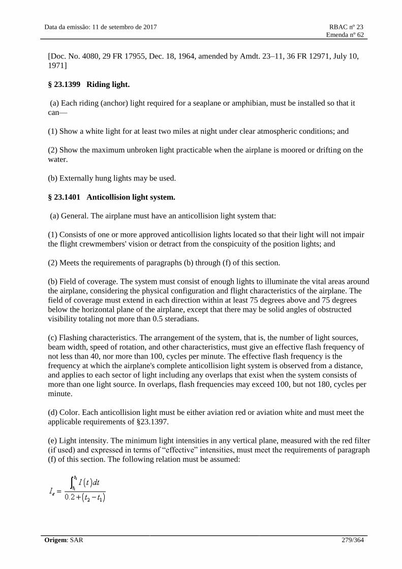
Data da emissão: 11 de setembro de 2017 RBAC nº 23
Emenda nº 62
Origem: SAR 279/364
[Doc. No. 4080, 29 FR 17955, Dec. 18, 1964, amended by Amdt. 23–11, 36 FR 12971, July 10,
1971]
§ 23.1399 Riding light.
(a) Each riding (anchor) light required for a seaplane or amphibian, must be installed so that it
can—
(1) Show a white light for at least two miles at night under clear atmospheric conditions; and
(2) Show the maximum unbroken light practicable when the airplane is moored or drifting on the
water.
(b) Externally hung lights may be used.
§ 23.1401 Anticollision light system.
(a) General. The airplane must have an anticollision light system that:
(1) Consists of one or more approved anticollision lights located so that their light will not impair
the flight crewmembers' vision or detract from the conspicuity of the position lights; and
(2) Meets the requirements of paragraphs (b) through (f) of this section.
(b) Field of coverage. The system must consist of enough lights to illuminate the vital areas around
the airplane, considering the physical configuration and flight characteristics of the airplane. The
field of coverage must extend in each direction within at least 75 degrees above and 75 degrees
below the horizontal plane of the airplane, except that there may be solid angles of obstructed
visibility totaling not more than 0.5 steradians.
(c) Flashing characteristics. The arrangement of the system, that is, the number of light sources,
beam width, speed of rotation, and other characteristics, must give an effective flash frequency of
not less than 40, nor more than 100, cycles per minute. The effective flash frequency is the
frequency at which the airplane's complete anticollision light system is observed from a distance,
and applies to each sector of light including any overlaps that exist when the system consists of
more than one light source. In overlaps, flash frequencies may exceed 100, but not 180, cycles per
minute.
(d) Color. Each anticollision light must be either aviation red or aviation white and must meet the
applicable requirements of §23.1397.
(e) Light intensity. The minimum light intensities in any vertical plane, measured with the red filter
(if used) and expressed in terms of “effective” intensities, must meet the requirements of paragraph
(f) of this section. The following relation must be assumed:

Data da emissão: 11 de setembro de 2017 RBAC nº 23
Emenda nº 62
Origem: SAR 280/364
where:
I e=effective intensity (candles).
I(t) =instantaneous intensity as a function of time.
t 2− t 1=flash time interval (seconds).
Normally, the maximum value of effective intensity is obtained when t 2and t 1are chosen so that the
effective intensity is equal to the instantaneous intensity at t 2and t 1.
(f) Minimum effective intensities for anticollision lights. Each anticollision light effective intensity
must equal or exceed the applicable values in the following table.
Angle above or below the horizontal plane Effective intensity (candles)
0° to 5° 400
5° to 10° 240
10° to 20° 80
20° to 30° 40
30° to 75° 20
[Doc. No. 4080, 29 FR 17955, Dec. 18, 1964, as amended by Amdt. 23–11, 36 FR 12972, July 10,
1971; Amdt. 23–20, 42 FR 36969, July 18, 1977; Amdt. 23–49, 61 FR 5169, Feb. 9, 1996]
Safety Equipment
§ 23.1411 General.
(a) Required safety equipment to be used by the flight crew in an emergency, such as automatic
liferaft releases, must be readily accessible.
(b) Stowage provisions for required safety equipment must be furnished and must—
(1) Be arranged so that the equipment is directly accessible and its location is obvious; and
(2) Protect the safety equipment from damage caused by being subjected to the inertia loads
resulting from the ultimate static load factors specified in §23.561(b)(3) of this part.
[Amdt. 23–17, 41 FR 55465, Dec. 20, 1976, as amended by Amdt. 23–36, 53 FR 30815, Aug. 15,
1988]
§ 23.1415 Ditching equipment.
(a) Emergency flotation and signaling equipment required by any operating rule in this chapter
must be installed so that it is readily available to the crew and passengers.

Data da emissão: 11 de setembro de 2017 RBAC nº 23
Emenda nº 62
Origem: SAR 281/364
(b) Each raft and each life preserver must be approved.
(c) Each raft released automatically or by the pilot must be attached to the airplane by a line to keep
it alongside the airplane. This line must be weak enough to break before submerging the empty raft
to which it is attached.
(d) Each signaling device required by any operating rule in this chapter, must be accessible,
function satisfactorily, and must be free of any hazard in its operation.
§ 23.1416 Pneumatic de-icer boot system.
If certification with ice protection provisions is desired and a pneumatic de-icer boot system is
installed—
(a) The system must meet the requirements specified in §23.1419.
(b) The system and its components must be designed to perform their intended function under any
normal system operating temperature or pressure, and
(c) Means to indicate to the flight crew that the pneumatic de-icer boot system is receiving adequate
pressure and is functioning normally must be provided.
[Amdt. 23–23, 43 FR 50593, Oct. 30, 1978]
§ 23.1419 Ice protection.
If certification with ice protection provisions is desired, compliance with the requirements of this
section and other applicable sections of this part must be shown:
(a) An analysis must be performed to establish, on the basis of the airplane's operational needs, the
adequacy of the ice protection system for the various components of the airplane. In addition, tests
of the ice protection system must be conducted to demonstrate that the airplane is capable of
operating safely in continuous maximum and intermittent maximum icing conditions, as described
in appendix C of part 25 of this chapter. As used in this section, “Capable of operating safely,”
means that airplane performance, controllability, maneuverability, and stability must not be less
than that required in part 23, subpart B.
(b) Except as provided by paragraph (c) of this section, in addition to the analysis and physical
evaluation prescribed in paragraph (a) of this section, the effectiveness of the ice protection system
and its components must be shown by flight tests of the airplane or its components in measured
natural atmospheric icing conditions and by one or more of the following tests, as found necessary
to determine the adequacy of the ice protection system—
(1) Laboratory dry air or simulated icing tests, or a combination of both, of the components or
models of the components.
(2) Flight dry air tests of the ice protection system as a whole, or its individual components.
(3) Flight test of the airplane or its components in measured simulated icing conditions.

Data da emissão: 11 de setembro de 2017 RBAC nº 23
Emenda nº 62
Origem: SAR 282/364
(c) If certification with ice protection has been accomplished on prior type certificated airplanes
whose designs include components that are thermodynamically and aerodynamically equivalent to
those used on a new airplane design, certification of these equivalent components may be
accomplished by reference to previously accomplished tests, required in §23.1419 (a) and (b),
provided that the applicant accounts for any differences in installation of these components.
(d) A means must be identified or provided for determining the formation of ice on the critical parts
of the airplane. Adequate lighting must be provided for the use of this means during night
operation. Also, when monitoring of the external surfaces of the airplane by the flight crew is
required for operation of the ice protection equipment, external lighting must be provided that is
adequate to enable the monitoring to be done at night. Any illumination that is used must be of a
type that will not cause glare or reflection that would handicap crewmembers in the performance of
their duties. The Airplane Flight Manual or other approved manual material must describe the
means of determining ice formation and must contain information for the safe operation of the
airplane in icing conditions.
[Doc. No. 26344, 58 FR 18977, Apr. 9, 1993]
Miscellaneous Equipment
23.1431 Electronic equipment.
(a) In showing compliance with paragraphs
23.1309(a), (b), and (c) of this RBAC with
respect to radio and electronic equipment and
their installations, critical environmental
conditions must be considered.
(b) Radio and electronic equipment, controls,
and wiring must be installed so that operation
of any unit or system of units will not adversely
affect the simultaneous operation of any other
radio or electronic unit, or system of units,
required by this RBAC.
(c) For those airplanes required to have more
than one flightcrew member, or whose
operation will require more than one flightcrew
member, the cockpit must be evaluated to
determine if the flightcrew members, when
seated at their duty station, can converse
without difficulty under the actual cockpit
noise conditions when the airplane is being
operated. If the airplane design includes
provision for the use of communication
headsets, the evaluation must also consider
conditions where headsets are being used. If
the evaluation shows conditions under which it
will be difficult to converse, an
23.1431 Equipamentos eletrônicos.
(a) Para demonstração de cumprimento com os
parágrafos 23.1309(a), (b) e (c) deste RBAC
com relação a rádios e equipamentos
eletrônicos e suas instalações, devem ser
consideradas as condições ambientais críticas.
(b) Os rádios e equipamentos eletrônicos,
controles e cablagem devem ser instalados de
forma que o funcionamento de qualquer
unidade ou sistema de unidades não afete
adversamente o funcionamento simultâneo de
qualquer outro rádio ou unidade eletrônica, ou
sistema de unidades, exigidos pelos RBAC.
(c) Para os aviões que exijam mais de um
tripulante de voo, ou que sua operação requeira
mais de um tripulante de voo, a cabine de
comando deve ser avaliada para determinar se
os membros da tripulação de voo, quando
sentados em seus postos de trabalho, podem
conversar sem dificuldade nas condições reais
de ruído da cabine de comando quando o avião
estiver em operação. Se o projeto do avião
incluir provisões para o uso de fones de ouvido
para comunicação, a avaliação também deve
considerar condições onde os fones de ouvido
estejam em uso. Se a avaliação mostrar
condições nas quais será difícil conversar, será
Data da emissão: 11 de setembro de 2017 RBAC nº 23
Emenda nº 62
Origem: SAR 283/364
intercommunication system must be provided.
(d) If installed communication equipment
includes transmitter “off-on” switching, that
switching means must be designed to return
from the “transmit” to the “off” position when
it is released and ensure that the transmitter
will return to the off (non transmitting) state.
(e) If provisions for the use of communication
headsets are provided, it must be demonstrated
that the flightcrew members will receive all
aural warnings under the actual cockpit noise
conditions when the airplane is being operated
when any headset is being used.
exigido um sistema de intercomunicação.
(d) Se o equipamento de comunicação
instalado incluir um transmissor com
chaveamento “desliga-liga”, este modo de
chaveamento deve ser projetado para retornar
da posição “transmissão” para a posição
“desligada” quando for solto e assegurar que o
transmissor retornará para o estado desligado
(não transmitindo).
(e) Se forem fornecidas provisões para o uso de
fones de ouvido para comunicação, deve-se
demonstrar que os membros da tripulação de
voo receberão todos os alarmes sonoros nas
condições reais de ruído da cabine de comando
quando o avião estiver em operação e qualquer
fone de ouvido estiver em uso.
[Doc. No. 26344, 58 FR 18977, Apr. 9, 1993, as amended by Amdt. 23-49, 61 FR 5169, Feb. 9,
1996; Amdt. 23-62, 76 FR 75761, Dec. 2, 2011]
[Resolução nº 446, de 06.09.2017]
§ 23.1435 Hydraulic systems.
(a) Design. Each hydraulic system must be designed as follows:
(1) Each hydraulic system and its elements must withstand, without yielding, the structural loads
expected in addition to hydraulic loads.
(2) A means to indicate the pressure in each hydraulic system which supplies two or more primary
functions must be provided to the flight crew.
(3) There must be means to ensure that the pressure, including transient (surge) pressure, in any part
of the system will not exceed the safe limit above design operating pressure and to prevent
excessive pressure resulting from fluid volumetric changes in all lines which are likely to remain
closed long enough for such changes to occur.
(4) The minimum design burst pressure must be 2.5 times the operating pressure.
(b) Tests. Each system must be substantiated by proof pressure tests. When proof tested, no part of
any system may fail, malfunction, or experience a permanent set. The proof load of each system
must be at least 1.5 times the maximum operating pressure of that system.
(c) Accumulators. A hydraulic accumulator or reservoir may be installed on the engine side of any
firewall if—
(1) It is an integral part of an engine or propeller system, or

Data da emissão: 11 de setembro de 2017 RBAC nº 23
Emenda nº 62
Origem: SAR 284/364
(2) The reservoir is nonpressurized and the total capacity of all such nonpressurized reservoirs is
one quart or less.
[Doc. No. 4080, 29 FR 17955, Dec. 18, 1964, as amended by Amdt. 23–7, 34 FR 13096, Aug. 13,
1969; Amdt. 23–14, 38 FR 31824, Nov. 19, 1973; Amdt. 23–43, 58 FR 18977, Apr. 9, 1993; Amdt.
23–49, 61 FR 5170, Feb. 9, 1996]
§ 23.1437 Accessories for multiengine airplanes.
For multiengine airplanes, engine-driven accessories essential to safe operation must be distributed
among two or more engines so that the failure of any one engine will not impair safe operation
through the malfunctioning of these accessories.
§ 23.1438 Pressurization and pneumatic systems.
(a) Pressurization system elements must be burst pressure tested to 2.0 times, and proof pressure
tested to 1.5 times, the maximum normal operating pressure.
(b) Pneumatic system elements must be burst pressure tested to 3.0 times, and proof pressure tested
to 1.5 times, the maximum normal operating pressure.
(c) An analysis, or a combination of analysis and test, may be substituted for any test required by
paragraph (a) or (b) of this section if the Administrator finds it equivalent to the required test.
[Amdt. 23–20, 42 FR 36969, July 18, 1977]
§ 23.1441 Oxygen equipment and supply.
(a) If certification with supplemental oxygen equipment is requested, or the airplane is approved
for operations at or above altitudes where oxygen is required to be used by the operating rules,
oxygen equipment must be provided that meets the requirements of this section and §§23.1443
through 23.1449. Portable oxygen equipment may be used to meet the requirements of this part if
the portable equipment is shown to comply with the applicable requirements, is identified in the
airplane type design, and its stowage provisions are found to be in compliance with the
requirements of §23.561.
(b) The oxygen system must be free from hazards in itself, in its method of operation, and its effect
upon other components.
(c) There must be a means to allow the crew to readily determine, during the flight, the quantity of
oxygen available in each source of supply.
(d) Each required flight crewmember must be provided with—
(1) Demand oxygen equipment if the airplane is to be certificated for operation above 25,000 feet.
(2) Pressure demand oxygen equipment if the airplane is to be certificated for operation above
40,000 feet.
Data da emissão: 11 de setembro de 2017 RBAC nº 23
Emenda nº 62
Origem: SAR 285/364
(e) There must be a means, readily available to the crew in flight, to turn on and to shut off the
oxygen supply at the high pressure source. This shutoff requirement does not apply to chemical
oxygen generators.
[Amdt. 23–9, 35 FR 6386, Apr. 21, 1970, as amended by Amdt. 23–43, 58 FR 18978, Apr. 9, 1993]
23.1443 Minimum mass flow of
supplemental oxygen.
(a) If the airplane is to be certified above
41.000 feet (12.497 meters), a continuous flow
oxygen system must be provided for each
passenger.
(b) If continuous flow oxygen equipment is
installed, an applicant must show compliance
with the requirements of either paragraphs
(b)(1) and (b)(2) or paragraph (b)(3) of this
section:
(1) For each passenger, the minimum mass
flow of supplemental oxygen required at
various cabin pressure altitudes may not be less
than the flow required to maintain, during
inspiration and while using the oxygen
equipment (including masks) provided, the
following mean tracheal oxygen partial
pressures:
(i) At cabin pressure altitudes above 10.000
feet (3.048 meters) up to and including 18.500
feet (5.639 meters), a mean tracheal oxygen
partial pressure of 100 mm Hg when breathing
15 liters per minute, Body Temperature,
Pressure, Saturated (BTPS) and with a tidal
volume of 700 cc with a constant time interval
between respirations;
(ii) At cabin pressure altitudes above 18.500
feet (5.639 meters) up to and including 40.000
feet (12.192 meters), a mean tracheal oxygen
partial pressure of 83,8 mm Hg when breathing
30 liters per minute, BTPS, and with a tidal
volume of 1.100 cc with a constant time
interval between respirations.
(2) For each flight crewmember, the minimum
mass flow may not be less than the flow
required to maintain, during inspiration, a mean
23.1443 Fluxo mássico mínimo de oxigênio
suplementar.
(a) Se o avião for ser certificado para
operações acima de 41.000 pés (12.497
metros), deve ser providenciado para cada
passageiro um sistema de fluxo contínuo de
oxigênio.
(b) Se estiver instalado um equipamento de
fluxo contínuo de oxigênio, o requerente deve
demonstrar cumprimento com os requisitos de
ambos os parágrafos (b)(1) e (b)(2) ou o
parágrafo (b)(3) desta seção:
(1) Para cada passageiro, o fluxo mínimo de
massa de oxigênio suplementar necessário em
várias altitudes de pressão de cabine não pode
ser menor do que o fluxo necessário para
manter, durante a inspiração e com o uso do
equipamento de oxigênio fornecido (incluindo
máscaras), as seguintes pressões parciais
médias de oxigênio traqueal:
(i) Para altitudes de pressão de cabine acima de
10.000 pés (3.048 metros) até 18.500 pés
(5.639 metros) inclusive, uma pressão parcial
média de oxigênio traqueal de 100 mmHg
quando respirando 15 litros por minuto, à
Temperatura-Pressão Corporal Saturada (Body
Temperature, Pressure, Saturated - BTPS) e
com um volume corrente de 700 cc., com um
intervalo de tempo constante entre as
respirações;
(ii) Para altitudes de pressão de cabine acima
de 18.500 pés (5.639 metros) até 40.000 pés
(12.192 metros) inclusive, uma pressão parcial
média de oxigênio traqueal de 83,8 mmHg
quando respirando 30 litros por minuto, BTPS,
e com um volume corrente de 1.100 cc., com
um intervalo de tempo constante entre as
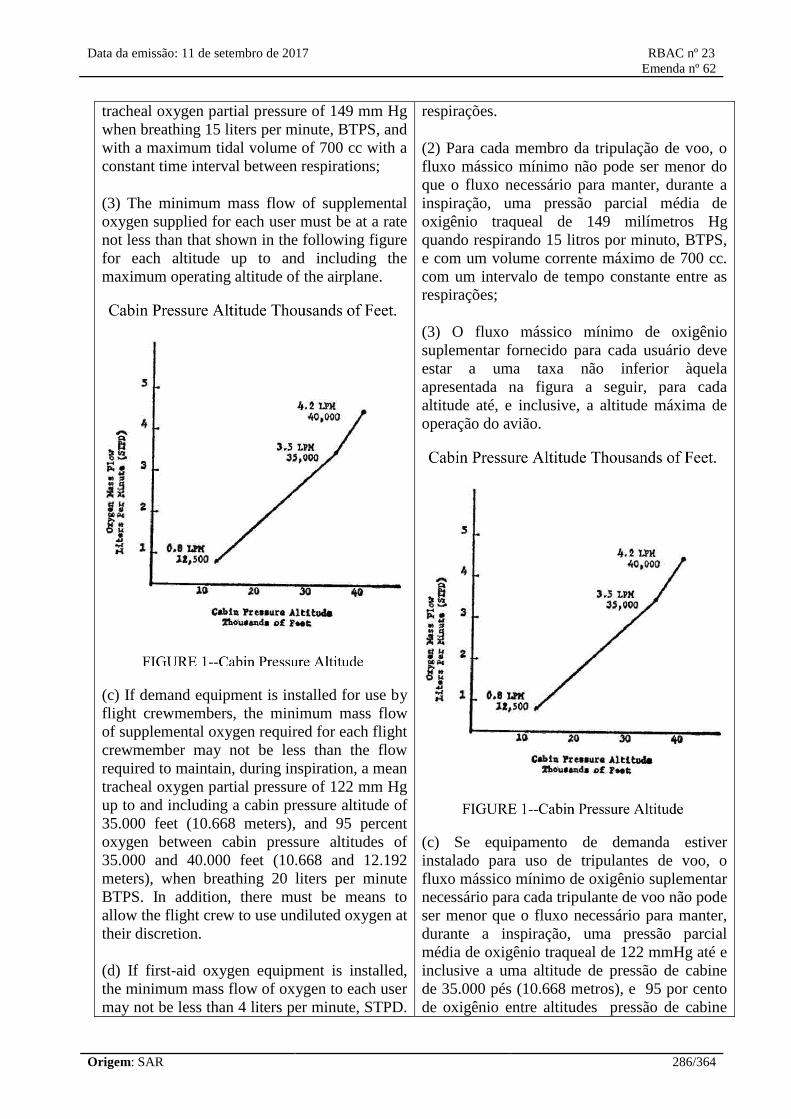
Data da emissão: 11 de setembro de 2017 RBAC nº 23
Emenda nº 62
Origem: SAR 286/364
tracheal oxygen partial pressure of 149 mm Hg
when breathing 15 liters per minute, BTPS, and
with a maximum tidal volume of 700 cc with a
constant time interval between respirations;
(3) The minimum mass flow of supplemental
oxygen supplied for each user must be at a rate
not less than that shown in the following figure
for each altitude up to and including the
maximum operating altitude of the airplane.
(c) If demand equipment is installed for use by
flight crewmembers, the minimum mass flow
of supplemental oxygen required for each flight
crewmember may not be less than the flow
required to maintain, during inspiration, a mean
tracheal oxygen partial pressure of 122 mm Hg
up to and including a cabin pressure altitude of
35.000 feet (10.668 meters), and 95 percent
oxygen between cabin pressure altitudes of
35.000 and 40.000 feet (10.668 and 12.192
meters), when breathing 20 liters per minute
BTPS. In addition, there must be means to
allow the flight crew to use undiluted oxygen at
their discretion.
(d) If first-aid oxygen equipment is installed,
the minimum mass flow of oxygen to each user
may not be less than 4 liters per minute, STPD.
respirações.
(2) Para cada membro da tripulação de voo, o
fluxo mássico mínimo não pode ser menor do
que o fluxo necessário para manter, durante a
inspiração, uma pressão parcial média de
oxigênio traqueal de 149 milímetros Hg
quando respirando 15 litros por minuto, BTPS,
e com um volume corrente máximo de 700 cc.
com um intervalo de tempo constante entre as
respirações;
(3) O fluxo mássico mínimo de oxigênio
suplementar fornecido para cada usuário deve
estar a uma taxa não inferior àquela
apresentada na figura a seguir, para cada
altitude até, e inclusive, a altitude máxima de
operação do avião.
(c) Se equipamento de demanda estiver
instalado para uso de tripulantes de voo, o
fluxo mássico mínimo de oxigênio suplementar
necessário para cada tripulante de voo não pode
ser menor que o fluxo necessário para manter,
durante a inspiração, uma pressão parcial
média de oxigênio traqueal de 122 mmHg até e
inclusive a uma altitude de pressão de cabine
de 35.000 pés (10.668 metros), e 95 por cento
de oxigênio entre altitudes pressão de cabine

Data da emissão: 11 de setembro de 2017 RBAC nº 23
Emenda nº 62
Origem: SAR 287/364
However, there may be a means to decrease
this flow to not less than 2 liters per minute,
STPD, at any cabin altitude. The quantity of
oxygen required is based upon an average flow
rate of 3 liters per minute per person for whom
first-aid oxygen is required.
(e) As used in this section:
(1) BTPS means Body Temperature, and
Pressure, Saturated (which is 37 °C, and the
ambient pressure to which the body is exposed,
minus 47 mm Hg, which is the tracheal
pressure displaced by water vapor pressure
when the breathed air becomes saturated with
water vapor at 37 °C);
(2) STPD means Standard, Temperature, and
Pressure, Dry (which is 0 °C at 760 mm Hg
with no water vapor).
de 35.000 e 40.000 pés (10.668 e 12.192
metros), quando respirando 20 litros por
minuto BTPS. Além disso, deve haver meios
para permitir que a tripulação use oxigênio
puro a seu critério.
(d) Se equipamento de oxigênio para primeiros
socorros estiver instalado, o fluxo mássico
mínimo de oxigênio para cada usuário não
pode ser inferior a 4 litros por minuto, STPD.
No entanto, pode haver um meio de diminuir
esse fluxo para um mínimo de 2 litros por
minuto, STPD, em qualquer altitude de cabine.
O oxigênio necessário é baseado em uma vazão
média de 3 litros por minuto por pessoa que
requeira oxigênio de primeiros socorros.
(e) Como usados nesta seção:
(1) BTPS significa Temperatura e Pressão
Corporal Saturada (Body Temperature, and
Pressure, Saturated) que é igual a 37 ° C e a
pressão ambiente a qual o corpo é exposto
menos 47 mmHg, que é a pressão traqueal
deslocada pela pressão de vapor de água
quando o ar respirado se torna saturado com
vapor de água a 37 ° C;
(2) STPD significa Pressão e Temperatura
Padrão Seca (Standard Temperature and
Pressure, Dry), que é de 0°C a 760 mmHg sem
vapor de água.
[Doc. No. FAA-2009-0738, 76 FR 75761, Dec. 2, 2011]
[Resolução nº 446, de 06.09.2017]
23.1445 Oxygen distribution system.
(a) Except for flexible lines from oxygen
outlets to the dispensing units, or where shown
to be otherwise suitable to the installation,
nonmetallic tubing must not be used for any
oxygen line that is normally pressurized during
flight.
(b) Nonmetallic oxygen distribution lines must
not be routed where they may be subjected to
elevated temperatures, electrical arcing, and
23.1445 Sistemas de distribuição de
oxigênio.
(a) Exceto para linhas flexíveis conectando as
tomadas de oxigênio com as máscaras, ou onde
foi demonstrada adequação à instalação, tubos
não-metálicos não podem ser utilizados para
qualquer linha de oxigênio que seja
normalmente pressurizada durante o vôo.
(b) Linhas de distribuição de oxigênio não
metálicas não podem passar em locais sujeitos

Data da emissão: 11 de setembro de 2017 RBAC nº 23
Emenda nº 62
Origem: SAR 288/364
released flammable fluids that might result
from any probable failure.
(c) If the flight crew and passengers share a
common source of oxygen, a means to
separately reserve the minimum supply
required by the flight crew must be provided.
a temperaturas elevadas, arcos elétricos e
líquidos inflamáveis que possam ser liberados
em qualquer falha provável.
(c) Se a tripulação e os passageiros
compartilharem a mesma fonte de oxigênio,
devem ser providenciados meios para reservar
separadamente o suprimento mínimo
necessário para a tripulação de vôo.
[Doc. No. 26344, 58 FR 18978, Apr. 9, 1993, as amended by Amdt. 23-62, 76 FR 75762, Dec. 2,
2011]
[Resolução nº 446, de 06.09.2017]
23.1447 Equipment standards for oxygen
dispensing units.
If oxygen dispensing units are installed, the
following apply:
(a) There must be an individual dispensing unit
for each occupant for whom supplemental
oxygen is to be supplied. Each dispensing unit
must:
(1) Provide for effective utilization of the
oxygen being delivered to the unit;
(2) Be capable of being readily placed into
position on the face of the user;
(3) Be equipped with a suitable means to retain
the unit in position on the face;
(4) If radio equipment is installed, the
flightcrew oxygen dispensing units must be
designed to allow the use of that equipment and
to allow communication with any other
required crew member while at their assigned
duty station.
(b) If certification for operation up to and
including 18,000 feet (5.486 meters) (MSL) is
requested, each oxygen dispensing unit must:
(1) Cover the nose and mouth of the user; or
(2) Be a nasal cannula, in which case one
23.1447 Requisitos de equipamentos para
unidades de distribuição de oxigênio.
Se houverem máscaras de oxigênio instaladas,
o seguinte se aplica:
(a) Deve haver uma máscara individual para
cada ocupante para quem o oxigênio
suplementar será fornecido. Cada máscara
deve:
(1) Prover utilização eficaz do oxigênio que
está sendo entregue à máscara;
(2) Ser capaz de ser facilmente colocada em
posição sobre o rosto do usuário;
(3) Estar equipada com meios adequados para
manter a máscara em posição sobre o rosto;
(4) Se houver equipamento de rádio instalado,
as máscaras de oxigênio dos tripulantes devem
ser projetadas para permitir o uso desse
equipamento e para permitir a comunicação
com qualquer outro membro da tripulação
exigida enquanto no seu posto de serviço.
(b) Se é solicitada certificação para operação
até e inclusive a 18.000 pés (5.486 metros)
(MSL), cada máscara de oxigênio deve:
(1) Cobrir o nariz e a boca do usuário; ou
(2) Ser uma cânula nasal, neste caso deve estar

Data da emissão: 11 de setembro de 2017 RBAC nº 23
Emenda nº 62
Origem: SAR 289/364
oxygen dispensing unit covering both the nose
and mouth of the user must be available. In
addition, each nasal cannula or its connecting
tubing must have permanently affixed:
(i) A visible warning against smoking while in
use;
(ii) An illustration of the correct method of
donning; and
(iii) A visible warning against use with nasal
obstructions or head colds with resultant nasal
congestion.
(c) If certification for operation above 18.000
feet (5.486 meters) (MSL) is requested, each
oxygen dispensing unit must cover the nose
and mouth of the user.
(d) For a pressurized airplane designed to
operate at flight altitudes above 25.000 feet
(7.620 meters) (MSL), the dispensing units
must meet the following:
(1) The dispensing units for passengers must be
connected to an oxygen supply terminal and be
immediately available to each occupant
wherever seated;
(2) The dispensing units for crewmembers
must be automatically presented to each
crewmember before the cabin pressure altitude
exceeds 15.000 feet (4.572 meters), or the units
must be of the quick-donning type, connected
to an oxygen supply terminal that is
immediately available to crewmembers at their
duty station.
(e) If certification for operation above 30.000
feet (9.144 meters) is requested, the dispensing
units for passengers must be automatically
presented to each occupant before the cabin
pressure altitude exceeds 15.000 feet (4.572
meters).
(f) If an automatic dispensing unit (hose and
mask, or other unit) system is installed, the
crew must be provided with a manual means to
disponível uma máscara de oxigênio que cubra
o nariz e boca do usuário. Além disso, cada
cânula nasal ou seus tubos de ligação devem ter
permanentemente afixados:
(i) Uma advertência visível contra fumar
durante a utilização;
(ii) Uma ilustração do método correto de
colocar; e
(iii) um aviso visível contra o uso com
obstrução nasal ou resfriados com congestão
nasal resultante.
(c) Se for solicitada certificação para operação
acima de 18.000 pés (5.486 metros) (MSL),
cada máscara de oxigênio deve cobrir o nariz e
a boca do usuário.
(d) Para um avião pressurizado projetado para
operar em altitudes de voo acima de 25.000 pés
(7.620 metros) (MSL), as máscaras devem
satisfazer o seguinte:
(1) As máscaras para os passageiros devem ser
conectadas a um terminal de fornecimento de
oxigênio e estar imediatamente disponíveis
para cada ocupante sentado;
(2) As máscaras para tripulantes devem ser
automaticamente disponibilizadas a cada
membro da tripulação antes que a altitude
pressão de cabine ultrapasse 15000 pés (4.572
metros), ou as máscaras devem ser de
colocação rápida, conectadas a um terminal de
fornecimento de oxigênio imediatamente
disponível para os membros da tripulação em
suas estações de trabalho.
(e) Se for solicitada certificação para operar
acima de 30.000 pés (9.144 metros), as
máscaras para passageiros devem ser
disponibilizadas automaticamente a cada
ocupante antes que a altitude de pressão de
cabine exceda 15.000 pés (4.572 metros).
(f) Se uma unidade automática de suprimento
(mangueira e máscara, ou outra unidade)
Data da emissão: 11 de setembro de 2017 RBAC nº 23
Emenda nº 62
Origem: SAR 290/364
make the dispensing units immediately
available in the event of failure of the
automatic system.
(g) If the airplane is to be certified for
operation above 41.000 feet (12.497 meters), a
quickdonning oxygen mask system, with a
pressure demand, mask mounted regulator
must be provided for the flight crew. This
dispensing unit must be immediately available
to the flight crew when seated at their station
and installed so that it:
(1) Can be placed on the face from its ready
position, properly secured, sealed, and
supplying oxygen upon demand, with one
hand, within five seconds and without
disturbing eyeglasses or causing delay in
proceeding with emergency duties; and
(2) Allows, while in place, the performance of
normal communication functions.
estiver instalada, deverá haver uma forma
manual e imediata para a tripulação
disponibilizar as unidades de suprimento, no
caso de falha do sistema automático.
(g) Se o avião for para ser certificado para
operação acima de 41.000 pés (12.497 metros),
deve ser providenciado para a tripulação de voo
máscara de oxigênio de colocação rápida e com
regulador por demanda pressurizada. Esta
unidade de fornecimento deve estar disponível
imediatamente para a tripulação de voo quando
sentada na sua estação de trabalho e instalada
de modo que:
(1) Possa ser posicionada sobre a face, a partir
de sua posição de instalação, adequadamente
suportada, selada e fornecendo oxigênio sob
demanda, com uma mão dentro de cinco
segundos, e sem interferir com óculos ou
causar atraso na execução de atividades de
emergência; e
(2) Permita, quando colocada, o desempenho
de funções de comunicação normais.
[Amdt. 23-9, 35 FR 6387, Apr. 21, 1970, as amended by Amdt. 23-20, 42 FR 36969, July 18, 1977;
Amdt. 23-30, 49 FR 7340, Feb. 28, 1984; Amdt. 23-43, 58 FR 18978, Apr. 9, 1993; Amdt. 23-49,
61 FR 5170, Feb. 9, 1996; Amdt. 23-62, 76 FR 75762, Dec. 2, 2011]
[Resolução nº 446, de 06.09.2017]
§ 23.1449 Means for determining use of oxygen.
There must be a means to allow the crew to determine whether oxygen is being delivered to the
dispensing equipment.
[Amdt. 23–9, 35 FR 6387, Apr. 21, 1970]
§ 23.1450 Chemical oxygen generators.
(a) For the purpose of this section, a chemical oxygen generator is defined as a device which
produces oxygen by chemical reaction.
(b) Each chemical oxygen generator must be designed and installed in accordance with the
following requirements:
(1) Surface temperature developed by the generator during operation may not create a hazard to the
airplane or to its occupants.

Data da emissão: 11 de setembro de 2017 RBAC nº 23
Emenda nº 62
Origem: SAR 291/364
(2) Means must be provided to relieve any internal pressure that may be hazardous.
(c) In addition to meeting the requirements in paragraph (b) of this section, each portable chemical
oxygen generator that is capable of sustained operation by successive replacement of a generator
element must be placarded to show—
(1) The rate of oxygen flow, in liters per minute;
(2) The duration of oxygen flow, in minutes, for the replaceable generator element; and
(3) A warning that the replaceable generator element may be hot, unless the element construction is
such that the surface temperature cannot exceed 100 °F.
[Amdt. 23–20, 42 FR 36969, July 18, 1977]
§ 23.1451 Fire protection for oxygen equipment.
Oxygen equipment and lines must:
(a) Not be installed in any designed fire zones.
(b) Be protected from heat that may be generated in, or escape from, any designated fire zone.
(c) Be installed so that escaping oxygen cannot come in contact with and cause ignition of grease,
fluid, or vapor accumulations that are present in normal operation or that may result from the failure
or malfunction of any other system.
[Doc. No. 27806, 61 FR 5170, Feb. 9, 1996]
§ 23.1453 Protection of oxygen equipment from rupture.
(a) Each element of the oxygen system must have sufficient strength to withstand the maximum
pressure and temperature, in combination with any externally applied loads arising from
consideration of limit structural loads, that may be acting on that part of the system.
(b) Oxygen pressure sources and the lines between the source and the shutoff means must be:
(1) Protected from unsafe temperatures; and
(2) Located where the probability and hazard of rupture in a crash landing are minimized.
[Doc. No. 27806, 61 FR 5170, Feb. 9, 1996]
§ 23.1457 Cockpit voice recorders.
(a) Each cockpit voice recorder required by the operating rules of this chapter must be approved
and must be installed so that it will record the following:
(1) Voice communications transmitted from or received in the airplane by radio.

Data da emissão: 11 de setembro de 2017 RBAC nº 23
Emenda nº 62
Origem: SAR 292/364
(2) Voice communications of flight crewmembers on the flight deck.
(3) Voice communications of flight crewmembers on the flight deck, using the airplane's interphone
system.
(4) Voice or audio signals identifying navigation or approach aids introduced into a headset or
speaker.
(5) Voice communications of flight crewmembers using the passenger loudspeaker system, if there
is such a system and if the fourth channel is available in accordance with the requirements of
paragraph (c)(4)(ii) of this section.
(6) If datalink communication equipment is installed, all datalink communications, using an
approved data message set. Datalink messages must be recorded as the output signal from the
communications unit that translates the signal into usable data.
(b) The recording requirements of paragraph (a)(2) of this section must be met by installing a
cockpit-mounted area microphone, located in the best position for recording voice communications
originating at the first and second pilot stations and voice communications of other crewmembers
on the flight deck when directed to those stations. The microphone must be so located and, if
necessary, the preamplifiers and filters of the recorder must be so adjusted or supplemented, so that
the intelligibility of the recorded communications is as high as practicable when recorded under
flight cockpit noise conditions and played back. Repeated aural or visual playback of the record
may be used in evaluating intelligibility.
(c) Each cockpit voice recorder must be installed so that the part of the communication or audio
signals specified in paragraph (a) of this section obtained from each of the following sources is
recorded on a separate channel:
(1) For the first channel, from each boom, mask, or handheld microphone, headset, or speaker used
at the first pilot station.
(2) For the second channel from each boom, mask, or handheld microphone, headset, or speaker
used at the second pilot station.
(3) For the third channel—from the cockpit-mounted area microphone.
(4) For the fourth channel from:
(i) Each boom, mask, or handheld microphone, headset, or speaker used at the station for the third
and fourth crewmembers.
(ii) If the stations specified in paragraph (c)(4)(i) of this section are not required or if the signal at
such a station is picked up by another channel, each microphone on the flight deck that is used with
the passenger loudspeaker system, if its signals are not picked up by another channel.
(5) And that as far as is practicable all sounds received by the microphone listed in paragraphs
(c)(1), (2), and (4) of this section must be recorded without interruption irrespective of the position
of the interphone-transmitter key switch. The design shall ensure that sidetone for the flight crew is

Data da emissão: 11 de setembro de 2017 RBAC nº 23
Emenda nº 62
Origem: SAR 293/364
produced only when the interphone, public address system, or radio transmitters are in use.
(d) Each cockpit voice recorder must be installed so that:
(1) It receives its electrical power from the bus that provides the maximum reliability for operation
of the cockpit voice recorder without jeopardizing service to essential or emergency loads. The
cockpit voice recorder must remain powered for as long as possible without jeopardizing
emergency operation of the airplane;
(2) There is an automatic means to simultaneously stop the recorder and prevent each erasure
feature from functioning, within 10 minutes after crash impact; and
(3) There is an aural or visual means for preflight checking of the recorder for proper operation;
(4) Any single electrical failure external to the recorder does not disable both the cockpit voice
recorder and the flight data recorder;
(5) It has an independent power source—
(i) That provides 10 ± 1 minutes of electrical power to operate both the cockpit voice recorder and
cockpit-mounted area microphone;
(ii) That is located as close as practicable to the cockpit voice recorder; and
(iii) To which the cockpit voice recorder and cockpit-mounted area microphone are switched
automatically in the event that all other power to the cockpit voice recorder is interrupted either by
normal shutdown or by any other loss of power to the electrical power bus; and
(6) It is in a separate container from the flight data recorder when both are required. If used to
comply with only the cockpit voice recorder requirements, a combination unit may be installed.
(e) The recorder container must be located and mounted to minimize the probability of rupture of
the container as a result of crash impact and consequent heat damage to the recorder from fire.
(1) Except as provided in paragraph (e)(2) of this section, the recorder container must be located as
far aft as practicable, but need not be outside of the pressurized compartment, and may not be
located where aft-mounted engines may crush the container during impact.
(2) If two separate combination digital flight data recorder and cockpit voice recorder units are
installed instead of one cockpit voice recorder and one digital flight data recorder, the combination
unit that is installed to comply with the cockpit voice recorder requirements may be located near the
cockpit.
(f) If the cockpit voice recorder has a bulk erasure device, the installation must be designed to
minimize the probability of inadvertent operation and actuation of the device during crash impact.
(g) Each recorder container must:
(1) Be either bright orange or bright yellow;

Data da emissão: 11 de setembro de 2017 RBAC nº 23
Emenda nº 62
Origem: SAR 294/364
(2) Have reflective tape affixed to its external surface to facilitate its location under water; and
(3) Have an underwater locating device, when required by the operating rules of this chapter, on or
adjacent to the container which is secured in such manner that they are not likely to be separated
during crash impact.
[Amdt. 23–35, 53 FR 26142, July 11, 1988, as amended by Amdt. No. 23–58, 73 FR 12562, Mar. 7,
2008]
§ 23.1459 Flight data recorders.
(a) Each flight recorder required by the operating rules of this chapter must be installed so that:
(1) It is supplied with airspeed, altitude, and directional data obtained from sources that meet the
accuracy requirements of §§23.1323, 23.1325, and 23.1327, as appropriate;
(2) The vertical acceleration sensor is rigidly attached, and located longitudinally either within the
approved center of gravity limits of the airplane, or at a distance forward or aft of these limits that
does not exceed 25 percent of the airplane's mean aerodynamic chord;
(3) It receives its electrical power from the bus that provides the maximum reliability for operation
of the flight data recorder without jeopardizing service to essential or emergency loads. The flight
data recorder must remain powered for as long as possible without jeopardizing emergency
operation of the airplane;
(4) There is an aural or visual means for preflight checking of the recorder for proper recording of
data in the storage medium;
(5) Except for recorders powered solely by the engine-driven electrical generator system, there is an
automatic means to simultaneously stop a recorder that has a data erasure feature and prevent each
erasure feature from functioning, within 10 minutes after crash impact;
(6) Any single electrical failure external to the recorder does not disable both the cockpit voice
recorder and the flight data recorder; and
(7) It is in a separate container from the cockpit voice recorder when both are required. If used to
comply with only the flight data recorder requirements, a combination unit may be installed. If a
combination unit is installed as a cockpit voice recorder to comply with §23.1457(e)(2), a
combination unit must be used to comply with this flight data recorder requirement.
(b) Each nonejectable record container must be located and mounted so as to minimize the
probability of container rupture resulting from crash impact and subsequent damage to the record
from fire. In meeting this requirement the record container must be located as far aft as practicable,
but need not be aft of the pressurized compartment, and may not be where aft-mounted engines may
crush the container upon impact.
(c) A correlation must be established between the flight recorder readings of airspeed, altitude, and
heading and the corresponding readings (taking into account correction factors) of the first pilot's
instruments. The correlation must cover the airspeed range over which the airplane is to be
Data da emissão: 11 de setembro de 2017 RBAC nº 23
Emenda nº 62
Origem: SAR 295/364
operated, the range of altitude to which the airplane is limited, and 360 degrees of heading.
Correlation may be established on the ground as appropriate.
(d) Each recorder container must:
(1) Be either bright orange or bright yellow;
(2) Have reflective tape affixed to its external surface to facilitate its location under water; and
(3) Have an underwater locating device, when required by the operating rules of this chapter, on or
adjacent to the container which is secured in such a manner that they are not likely to be separated
during crash impact.
(e) Any novel or unique design or operational characteristics of the aircraft shall be evaluated to
determine if any dedicated parameters must be recorded on flight recorders in addition to or in place
of existing requirements.
[Amdt. 23–35, 53 FR 26143, July 11, 1988, as amended by Amdt. No. 23–58, 73 FR 12562, Mar. 7,
2008]
§ 23.1461 Equipment containing high energy rotors.
(a) Equipment, such as Auxiliary Power Units (APU) and constant speed drive units, containing
high energy rotors must meet paragraphs (b), (c), or (d) of this section.
(b) High energy rotors contained in equipment must be able to withstand damage caused by
malfunctions, vibration, abnormal speeds, and abnormal temperatures. In addition—
(1) Auxiliary rotor cases must be able to contain damage caused by the failure of high energy rotor
blades; and
(2) Equipment control devices, systems, and instrumentation must reasonably ensure that no
operating limitations affecting the integrity of high energy rotors will be exceeded in service.
(c) It must be shown by test that equipment containing high energy rotors can contain any failure of
a high energy rotor that occurs at the highest speed obtainable with the normal speed control
devices inoperative.
(d) Equipment containing high energy rotors must be located where rotor failure will neither
endanger the occupants nor adversely affect continued safe flight.
[Amdt. 23–20, 42 FR 36969, July 18, 1977, as amended by Amdt. 23–49, 61 FR 5170, Feb. 9,
1996]
Subpart G—Operating Limitations and Information
§ 23.1501 General.
(a) Each operating limitation specified in §§23.1505 through 23.1527 and other limitations and

Data da emissão: 11 de setembro de 2017 RBAC nº 23
Emenda nº 62
Origem: SAR 296/364
information necessary for safe operation must be established.
(b) The operating limitations and other information necessary for safe operation must be made
available to the crewmembers as prescribed in §§23.1541 through 23.1589.
[Amdt. 23–21, 43 FR 2319, Jan. 16, 1978]
23.1505 Airspeed limitations.
(a) The never-exceed speed VNE must be
established so that it is:
(1) Not less than 0,9 times the minimum value
of VD allowed under section 23.335; and
(2) Not more than the lesser of:
(i) 0,9 VD established under section 23.335; or
(ii) 0,9 times the maximum speed shown under
section 23.251.
(b) The maximum structural cruising speed
VNO must be established so that it is:
(1) Not less than the minimum value of VC
allowed under section 23.335; and
(2) Not more than the lesser of:
(i) VC established under section 23.335; or
(ii) 0,89 VNE established under paragraph (a) of
this section.
(c)(1) Paragraphs (a) and (b) of this section do
not apply to turbine airplanes or to airplanes for
which a design diving speed VD/MD is
established under paragraph 23.335(b)(4). For
those airplanes, a maximum operating limit
speed (VMO/MMO airspeed or Mach number,
whichever is critical at a particular altitude)
must be established as a speed that may not be
deliberately exceeded in any regime of flight
(climb, cruise, or descent) unless a higher
speed is authorized for flight test or pilot
training operations.
(2) VMO/MMO must be established so that it is
23.1505 Limitações de velocidade.
(a) Deve ser estabelecida a velocidade nunca a
ser excedida VNE de modo que ela seja:
(1) Não inferior a 0,9 vezes o valor mínimo da
VD permitida nos termos da seção 23.335, e
(2) Não mais do que o menor entre:
(i) 0,9 VD estabelecida nos termos da seção
23.335, ou
(ii) 0,9 vezes a velocidade máxima indicada na
seção 23.251.
(b) Deve ser estabelecida a velocidade máxima
estrutural de cruzeiro VNO de modo que seja:
(1) Não inferior ao valor mínimo da VC
permitida nos termos da seção 23.335, e
(2) Não mais do que o menor entre:
(i) VC estabelecida nos termos da seção 23.335,
ou
(ii) 0,89 VNE estabelecida no parágrafo (a)
desta seção.
(c)(1) Os parágrafos (a) e (b) desta seção não se
aplicam a aviões impulsionados por motor a
turbina ou a aviões para os quais uma
velocidade máxima de mergulho de projeto
VD/MD seja estabelecida nos termos do
parágrafo 23.335(b)(4). Para estes aviões, uma
velocidade limite máxima em operação
(VMO/MMO velocidade ou o número MACH, o
que for crítico a uma altitude particular) deve
ser estabelecida como uma velocidade que não
pode ser deliberadamente excedida em
qualquer regime de voo (subida, cruzeiro, ou

Data da emissão: 11 de setembro de 2017 RBAC nº 23
Emenda nº 62
Origem: SAR 297/364
not greater than the design cruising speed
VC/MC and so that it is sufficiently below
VD/MD, or VDF/MDF for jets, and the maximum
speed shown under section 23.251 to make it
highly improbable that the latter speeds will be
inadvertently exceeded in operations.
(3) The speed margin between VMO/MMO and
VD/MD, or VDF/MDF for jets, may not be less
than that determined under paragraph
23.335(b), or the speed margin found necessary
in the flight tests conducted under section
23.253.
descida), a menos que uma velocidade maior
seja autorizada para ensaios em voo ou
operações de treinamento de pilotos.
(2) Deve ser estabelecida a VMO/MMO de modo
que esta não seja maior do que a velocidade de
cruzeiro de projeto VC/MC e que seja
suficientemente inferior a VD/MD, ou VDF/MDF
para jatos, e a velocidade máxima indicada nos
termos da seção 23.251 de forma a tornar
altamente improvável que estas últimas
velocidades sejam inadvertidamente excedidas
em operação.
(3) A margem de velocidade entre VMO/MMO e
VD/MD, ou VDF/MDF para jatos não pode ser
inferior àquela determinada nos termos do
parágrafo 23.335(b) ou à margem de
velocidade considerada necessária nos ensaios
em voo realizados nos termos da seção 23.253.
[Doc. No. 4080, 29 FR 17955, Dec. 18, 1964, as amended by Amdt. 23-7, 34 FR 13096, Aug. 13,
1969; Amdt. 23-62, 76 FR 75762, Dec. 2, 2011]
[Resolução nº 446, de 06.09.2017]
§ 23.1507 Operating maneuvering speed.
The maximum operating maneuvering speed, VO, must be established as an operating limitation.
VOis a selected speed that is not greater than VS√n established in §23.335(c).
[Doc. No. 26269, 58 FR 42165, Aug. 6, 1993]
§ 23.1511 Flap extended speed.
(a) The flap extended speed V FEmust be established so that it is—
(1) Not less than the minimum value of VF allowed in §23.345(b); and
(2) Not more than VFestablished under §23.345(a), (c), and (d).
(b) Additional combinations of flap setting, airspeed, and engine power may be established if the
structure has been proven for the corresponding design conditions.
[Doc. No. 4080, 29 FR 17955, Dec. 18, 1964; 30 FR 258, Jan. 9, 1965, as amended by Amdt. 23–
50, 61 FR 5192, Feb. 9, 1996]
§ 23.1513 Minimum control speed.

Data da emissão: 11 de setembro de 2017 RBAC nº 23
Emenda nº 62
Origem: SAR 298/364
The minimum control speed V MC,determined under §23.149, must be established as an operating
limitation.
§ 23.1519 Weight and center of gravity.
The weight and center of gravity limitations determined under §23.23 must be established as
operating limitations.
§ 23.1521 Powerplant limitations.
(a) General. The powerplant limitations prescribed in this section must be established so that they
do not exceed the corresponding limits for which the engines or propellers are type certificated. In
addition, other powerplant limitations used in determining compliance with this part must be
established.
(b) Takeoff operation. The powerplant takeoff operation must be limited by—
(1) The maximum rotational speed (rpm);
(2) The maximum allowable manifold pressure (for reciprocating engines);
(3) The maximum allowable gas temperature (for turbine engines);
(4) The time limit for the use of the power or thrust corresponding to the limitations established in
paragraphs (b)(1) through (3) of this section; and
(5) The maximum allowable cylinder head (as applicable), liquid coolant and oil temperatures.
(c) Continuous operation. The continuous operation must be limited by—
(1) The maximum rotational speed;
(2) The maximum allowable manifold pressure (for reciprocating engines);
(3) The maximum allowable gas temperature (for turbine engines); and
(4) The maximum allowable cylinder head, oil, and liquid coolant temperatures.
(d) Fuel grade or designation. The minimum fuel grade (for reciprocating engines), or fuel
designation (for turbine engines), must be established so that it is not less than that required for the
operation of the engines within the limitations in paragraphs (b) and (c) of this section.
(e) Ambient temperature. For all airplanes except reciprocating engine-powered airplanes of 6,000
pounds or less maximum weight, ambient temperature limitations (including limitations for
winterization installations if applicable) must be established as the maximum ambient atmospheric
temperature at which compliance with the cooling provisions of §§23.1041 through 23.1047 is
shown.
Data da emissão: 11 de setembro de 2017 RBAC nº 23
Emenda nº 62
Origem: SAR 299/364
[Doc. No. 4080, 29 FR 17955, Dec. 18, 1964; 30 FR 258, Jan. 9, 1965, as amended by Amdt. 23–
21, 43 FR 2319, Jan. 16, 1978; Amdt. 23–45, 58 FR 42165, Aug. 6, 1993; Amdt. 23–50, 61 FR
5192, Feb. 9, 1996]
§ 23.1522 Auxiliary power unit limitations.
If an auxiliary power unit is installed, the limitations established for the auxiliary power must be
specified in the operating limitations for the airplane.
[Doc. No. 26269, 58 FR 42166, Aug. 6, 1993]
§ 23.1523 Minimum flight crew.
The minimum flight crew must be established so that it is sufficient for safe operation
considering—
(a) The workload on individual crewmembers and, in addition for commuter category airplanes,
each crewmember workload determination must consider the following:
(1) Flight path control,
(2) Collision avoidance,
(3) Navigation,
(4) Communications,
(5) Operation and monitoring of all essential airplane systems,
(6) Command decisions, and
(7) The accessibility and ease of operation of necessary controls by the appropriate crewmember
during all normal and emergency operations when at the crewmember flight station;
(b) The accessibility and ease of operation of necessary controls by the appropriate crewmember;
and
(c) The kinds of operation authorized under §23.1525.
[Amdt. 23–21, 43 FR 2319, Jan. 16, 1978, as amended by Amdt. 23–34, 52 FR 1834, Jan. 15, 1987]
§ 23.1524 Maximum passenger seating configuration.
The maximum passenger seating configuration must be established.
[Amdt. 23–10, 36 FR 2864, Feb. 11, 1971]
§ 23.1525 Kinds of operation.

Data da emissão: 11 de setembro de 2017 RBAC nº 23
Emenda nº 62
Origem: SAR 300/364
The kinds of operation authorized (e.g. VFR, IFR, day or night) and the meteorological conditions
(e.g. icing) to which the operation of the airplane is limited or from which it is prohibited, must be
established appropriate to the installed equipment.
[Doc. No. 26269, 58 FR 42166, Aug. 6, 1993]
23.1527 Maximum operating altitude.
(a) The maximum altitude up to which
operation is allowed, as limited by flight,
structural, powerplant, functional or equipment
characteristics, must be established.
(b) A maximum operating altitude limitation of
not more than 25.000 feet (7.620 m) must be
established for pressurized airplanes unless
compliance with paragraph 23.775(d) is shown.
23.1527 Altitude máxima de operação.
(a) A altitude máxima até a qual a operação é
permitida, limitada por características de voo,
estruturais, grupo motopropulsor, funcionais ou
de equipamentos, deve ser estabelecida.
(b) Uma limitação de altitude máxima de
operação de não mais que 25.000 pés (7.620 m)
deve ser estabelecida para aeronaves
pressurizadas, a menos que o cumprimento
com o parágrafo 23.775(d) seja demonstrado.
[Doc. No. 26269, 58 FR 42166, Aug. 6, 1993]
[Resolução nº 446, de 06.09.2017]
§ 23.1529 Instructions for Continued Airworthiness.
The applicant must prepare Instructions for Continued Airworthiness in accordance with appendix
G to this part that are acceptable to the Administrator. The instructions may be incomplete at type
certification if a program exists to ensure their completion prior to delivery of the first airplane or
issuance of a standard certificate of airworthiness, whichever occurs later.
[Amdt. 23–26, 45 FR 60171, Sept. 11, 1980]
Markings And Placards
§ 23.1541 General.
(a) The airplane must contain—
(1) The markings and placards specified in §§23.1545 through 23.1567; and
(2) Any additional information, instrument markings, and placards required for the safe operation if
it has unusual design, operating, or handling characteristics.
(b) Each marking and placard prescribed in paragraph (a) of this section—
(1) Must be displayed in a conspicuous place; and
(2) May not be easily erased, disfigured, or obscured.

Data da emissão: 11 de setembro de 2017 RBAC nº 23
Emenda nº 62
Origem: SAR 301/364
(c) For airplanes which are to be certificated in more than one category—
(1) The applicant must select one category upon which the placards and markings are to be based;
and
(2) The placards and marking information for all categories in which the airplane is to be
certificated must be furnished in the Airplane Flight Manual.
[Doc. No. 4080, 29 FR 17955, Dec. 18, 1964; 30 FR 258, Jan. 9, 1965, as amended by Amdt. 23–
21, 43 FR 2319, Jan. 16, 1978]
§ 23.1543 Instrument markings: General.
For each instrument—
(a) When markings are on the cover glass of the instrument, there must be means to maintain the
correct alignment of the glass cover with the face of the dial; and
(b) Each arc and line must be wide enough and located to be clearly visible to the pilot.
(c) All related instruments must be calibrated in compatible units.
[Doc. No. 4080, 29 FR 17955, Dec. 18, 1964; 30 FR 258, Jan. 9, 1965, as amended by Amdt. 23–
50, 61 FR 5192, Feb. 9, 1996]
23.1545 Airspeed indicator.
(a) Each airspeed indicator must be marked as
specified in paragraph (b) of this section, with
the marks located at the corresponding
indicated airspeeds.
(b) The following markings must be made:
(1) For the never-exceed speed VNE,a radial red
line.
(2) For the caution range, a yellow arc
extending from the red line specified in
paragraph (b)(1) of this section to the upper
limit of the green arc specified in paragraph
(b)(3) of this section.
(3) For the normal operating range, a green arc
with the lower limit at VS1 with maximum
weight and with landing gear and wing flaps
retracted, and the upper limit at the maximum
structural cruising speed VNO established under
23.1545 Indicador de velocidade no ar.
(a) Cada indicador de velocidade no ar deve
estar marcado como especificado no parágrafo
(b) desta seção, com as marcações localizadas
nas velocidades indicadas correspondentes.
(b) As seguintes marcações devem ser feitas:
(1) Para a velocidade nunca exceder (VNE),
uma linha radial vermelha.
(2) Para o intervalo de advertência, um arco
amarelo a partir da linha vermelha especificada
no parágrafo (b)(1) desta seção até o limite
superior do arco verde especificado no
parágrafo (b)(3) desta seção.
(3) Para o intervalo de operação normal, um
arco verde com o limite inferior na VS1 com
peso máximo e trem de pouso e flapes das asas
retraídos, e com o limite superior na velocidade
máxima estrutural de cruzeiro VNO estabelecida

Data da emissão: 11 de setembro de 2017 RBAC nº 23
Emenda nº 62
Origem: SAR 302/364
paragraph 23.1505(b).
(4) For the flap operating range, a white arc
with the lower limit at VS0 at the maximum
weight, and the upper limit at the flaps-
extended speed VFE established under section
23.1511.
(5) For reciprocating multiengine-powered
airplanes of 6.000 pounds (2.722 kg) or less
maximum weight, for the speed at which
compliance has been shown with paragraph
23.69(b) relating to rate of climb at maximum
weight and at sea level, a blue radial line.
(6) For reciprocating multiengine-powered
airplanes of 6.000 pounds (2.722 kg) or less
maximum weight, for the maximum value of
minimum control speed, VMC, (one-engine-
inoperative) determined under paragraph
23.149(b), a red radial line.
(c) If VNE or VNO vary with altitude, there must
be means to indicate to the pilot the appropriate
limitations throughout the operating altitude
range.
(d) Paragraphs (b)(1) through (b)(3) and
paragraph (c) of this section do not apply to
airplanes for which a maximum operating
speed VMO/MMO is established under paragraph
23.1505(c). For those airplanes, there must
either be a maximum allowable airspeed
indication showing the variation of VMO/MMO
with altitude or compressibility limitations (as
appropriate), or a radial red line marking for
VMO/MMO must be made at lowest value of
VMO/MMO established for any altitude up to the
maximum operating altitude for the airplane.
segundo o parágrafo 23.1505(b).
(4) Para o intervalo de operação do flap, um
arco branco com o limite inferior na VS0 no
peso máximo, e o limite superior na velocidade
de flapes estendidos VFE estabelecida na seção
23.1511.
(5) Para aviões de motor convencional
multimotoras de 6.000 libras (2.722 kg) ou
menos de peso máximo, uma linha radial azul
para a velocidade na qual o cumprimento com
o parágrafo 23.69(b) foi demonstrado para a
razão de subida no peso máximo e ao nível do
mar.
(6) Para aviões multimotores de motor
convencional de 6.000 libras (2.722 kg) ou
menos de peso máximo, uma linha radial
vermelha para o valor máximo da velocidade
mínima de controle, VMC, (um motor
inoperante) determinada de acordo com o
parágrafo 23.149(b).
(c) Se a VNE ou a VNO variam com a altitude,
deve haver um meio de indicar para o piloto as
limitações apropriadas ao longo do envelope de
altitude de operação.
(d) Os parágrafos (b)(1) a (b)(3) e o parágrafo
(c) desta seção não se aplicam a aviões para as
quais a velocidade máxima de operação
VMO/MMO é estabelecida de acordo com o
parágrafo 23.1505(c). Para esses aviões, deve
existir uma indicação de velocidade máxima do
ar permitida mostrando a variação de VMO/MMO
com a altitude ou limitações de
compressibilidade (conforme apropriado), ou
uma marcação com linha radial vermelha para
VMO/MMO deve ser feita no menor valor de
VMO/MMO estabelecido para todas as altitudes
até a altitude máxima de operação do avião.
[Doc. No. 4080, 29 FR 17955, Dec. 18, 1964, as amended by Amdt. 23-3, 30 FR 14240, Nov. 13,
1965; Amdt. 23-7, 34 FR 13097, Aug. 13, 1969; Amdt. 23-23, 43 FR 50593, Oct. 30, 1978; Amdt.
23-50, 61 FR 5193, Feb. 9, 1996; Amdt. 23-62, 76 FR 75762, Dec. 2, 2011]
[Resolução nº 446, de 06.09.2017]

Data da emissão: 11 de setembro de 2017 RBAC nº 23
Emenda nº 62
Origem: SAR 303/364
§ 23.1547 Magnetic direction indicator.
(a) A placard meeting the requirements of this section must be installed on or near the magnetic
direction indicator.
(b) The placard must show the calibration of the instrument in level flight with the engines
operating.
(c) The placard must state whether the calibration was made with radio receivers on or off.
(d) Each calibration reading must be in terms of magnetic headings in not more than 30 degree
increments.
(e) If a magnetic nonstabilized direction indicator can have a deviation of more than 10 degrees
caused by the operation of electrical equipment, the placard must state which electrical loads, or
combination of loads, would cause a deviation of more than 10 degrees when turned on.
[Doc. No. 4080, 29 FR 17955, Dec. 18, 1964; 30 FR 258, Jan. 9, 1965, as amended by Amdt. 23–
20, 42 FR 36969, July 18, 1977]
§ 23.1549 Powerplant and auxiliary power unit instruments.
For each required powerplant and auxiliary power unit instrument, as appropriate to the type of
instruments—
(a) Each maximum and, if applicable, minimum safe operating limit must be marked with a red
radial or a red line;
(b) Each normal operating range must be marked with a green arc or green line, not extending
beyond the maximum and minimum safe limits;
(c) Each takeoff and precautionary range must be marked with a yellow arc or a yellow line; and
(d) Each engine, auxiliary power unit, or propeller range that is restricted because of excessive
vibration stresses must be marked with red arcs or red lines.
[Amdt. 23–12, 41 FR 55466, Dec. 20, 1976, as amended by Amdt. 23–28, 47 FR 13315, Mar. 29,
1982; Amdt. 23–45, 58 FR 42166, Aug. 6, 1993]
§ 23.1551 Oil quantity indicator.
Each oil quantity indicator must be marked in sufficient increments to indicate readily and
accurately the quantity of oil.
§ 23.1553 Fuel quantity indicator.
A red radial line must be marked on each indicator at the calibrated zero reading, as specified in
§23.1337(b)(1).

Data da emissão: 11 de setembro de 2017 RBAC nº 23
Emenda nº 62
Origem: SAR 304/364
[Doc. No. 27807, 61 FR 5193, Feb. 9, 1996]
23.1555 Control markings.
(a) Each cockpit control, other than primary
flight controls and simple push button type
starter switches, must be plainly marked as to
its function and method of operation.
(b) Each secondary control must be suitably
marked.
(c) For powerplant fuel controls:
(1) Each fuel tank selector control must be
marked to indicate the position corresponding
to each tank and to each existing cross feed
position;
(2) If safe operation requires the use of any
tanks in a specific sequence, that sequence
must be marked on or near the selector for
those tanks;
(3) The conditions under which the full amount
of usable fuel in any restricted usage fuel tank
can safely be used must be stated on a placard
adjacent to the selector valve for that tank; and
(4) Each valve control for any engine of a
multiengine airplane must be marked to
indicate the position corresponding to each
engine controlled.
(d) Usable fuel capacity must be marked as
follows:
(1) For fuel systems having no selector
controls, the usable fuel capacity of the system
must be indicated at the fuel quantity indicator.
(2) For fuel systems having selector controls,
the usable fuel capacity available at each
selector control position must be indicated near
the selector control.
(3) For fuel systems having a calibrated fuel
quantity indication system complying with
paragraph 23.1337(b)(1) and accurately
23.1555 Marcas de comando.
(a) Cada comando da cabine de voo, diferente
dos comandos primários de voo e dos
interruptores de partida do tipo simples de
apertar, deve ser claramente marcado conforme
a sua função e método de operação.
(b) Cada comando secundário deve ser
adequadamente marcado.
(c) Para comandos de combustível do sistema
motopropulsor:
(1) Cada comando seletor do tanque de
combustível deve ser marcado para indicar a
posição correspondente a cada tanque e a cada
posição existente de alimentação cruzada;
(2) Se operação segura requerer o uso de
quaisquer tanques em uma sequência
específica, aquela sequência deve ser marcada
no seletor ou perto dele para aqueles tanques;
(3) As condições, sob as quais a quantidade
total de combustível utilizável em qualquer
tanque de combustível com uso restrito pode
ser usada com segurança, devem ser definidas
em um placar adjacente à válvula do seletor
para aquele tanque; e
(4) Cada comando de válvula para qualquer
motor de um avião com mais de um motor deve
ser marcado para indicar a posição
correspondente a cada motor comandado.
(d) A capacidade de combustível utilizável
deve ser marcada como segue:
(1) Para sistemas de combustível que não têm
nenhum comando seletor, a capacidade de
combustível utilizável do sistema deve ser
indicada no indicador de quantidade de
combustível.
(2) Para sistemas de combustível que têm
comandos seletores, a capacidade de
Data da emissão: 11 de setembro de 2017 RBAC nº 23
Emenda nº 62
Origem: SAR 305/364
displaying the actual quantity of usable fuel in
each selectable tank, no fuel capacity placards
outside of the fuel quantity indicator are
required.
(e) For accessory, auxiliary, and emergency
controls:
(1) If retractable landing gear is used, the
indicator required by section 23.729 of this
RBAC must be marked so that the pilot can, at
any time, ascertain that the wheels are secured
in the extreme positions; and
(2) Each emergency control must be red and
must be marked as to method of operation. No
control other than an emergency control, or a
control that serves an emergency function in
addition to its other functions, shall be this
color.
combustível utilizável disponível em cada
posição do comando seletor deve ser indicada
perto do comando seletor.
(3) Para sistemas de combustível que têm um
sistema calibrado de indicação da quantidade
de combustível que cumpre com o parágrafo
23.1337(b)(1) e que mostra com precisão a
quantidade real de combustível utilizável em
cada tanque selecionável, não são exigidos
placares de capacidade de combustível fora do
indicador da quantidade de combustível.
(e) Para comandos acessórios, auxiliares e de
emergência:
(1) Se trem de pouso retrátil é usado, o
indicador requerido pela seção 23.729 deve ser
marcado de maneira que o piloto possa, a
qualquer tempo, se certificar que as rodas estão
firmes nas posições extremas; e
(2) Cada comando de emergência deve ser
vermelho e deve ser marcado conforme o
método de operação. Nenhum comando
diferente de um comando de emergência, ou
nenhum comando que atende a uma função de
emergência em adição às suas outras funções,
deve ser desta cor.
[Doc. No. 4080, 29 FR 17955, Dec. 18, 1964; 30 FR 258, Jan. 9, 1965, as amended by Amdt. 23-
21, 43 FR 2319, Jan. 16, 1978; Amdt. 23-50, 61 FR 5193, Feb. 9, 1996; Amdt. 23-62, 76 FR 75763,
Dec. 2, 2011]
[Resolução nº 446, de 06.09.2017]
§ 23.1557 Miscellaneous markings and placards.
(a) Baggage and cargo compartments, and ballast location. Each baggage and cargo compartment,
and each ballast location, must have a placard stating any limitations on contents, including weight,
that are necessary under the loading requirements.
(b) Seats. If the maximum allowable weight to be carried in a seat is less than 170 pounds, a placard
stating the lesser weight must be permanently attached to the seat structure.
(c) Fuel, oil, and coolant filler openings. The following apply:
(1)Fuel filler openings must be marked at or near the filler cover with—

Data da emissão: 11 de setembro de 2017 RBAC nº 23
Emenda nº 62
Origem: SAR 306/364
(i) For reciprocating engine-powered airplanes—
(A) The word “Avgas”; and
(B) The minimum fuel grade.
(ii) For turbine engine-powered airplanes—
(A) The words “Jet Fuel”; and
(B) The permissible fuel designations, or references to the Airplane Flight Manual (AFM) for
permissible fuel designations.
(iii) For pressure fueling systems, the maximum permissible fueling supply pressure and the
maximum permissible defueling pressure.
(2) Oil filler openings must be marked at or near the filler cover with the word “Oil” and the
permissible oil designations, or references to the Airplane Flight Manual (AFM) for permissible oil
designations.
(3) Coolant filler openings must be marked at or near the filler cover with the word “Coolant”.
(d) Emergency exit placards. Each placard and operating control for each emergency exit must be
red. A placard must be near each emergency exit control and must clearly indicate the location of
that exit and its method of operation.
(e) The system voltage of each direct current installation must be clearly marked adjacent to its
exernal power connection.
[Doc. No. 4080, 29 FR 17955, Dec. 18, 1964; as amended by Amdt. 23–21, 42 FR 15042, Mar. 17,
1977; Amdt. 23–23, 43 FR 50594, Oct. 30, 1978; Amdt. 23–45, 58 FR 42166, Aug. 6, 1993; 73 FR
35063, June 20, 2008]
23.1559 Operating limitations placard.
(a) There must be a placard in clear view of the
pilot stating:
(1) That the airplane must be operated in
accordance with the Airplane Flight Manual;
and
(2) The certification category of the airplane to
which the placards apply.
(b) For airplanes certificated in more than one
category, there must be a placard in clear view
of the pilot stating that other limitations are
23.1559 Placar de limitações operacionais.
(a) Deve haver um placar claramente visível
para o piloto informando:
(1) Que o avião deve ser operado de acordo
com o manual de voo aprovado; e
(2) A categoria de certificação do avião para a
qual o placar se aplica.
(b) Para aviões certificados em mais de uma
categoria, deve haver um placar claramente
visível para o piloto informando que outras
limitações estão contidas no manual de voo
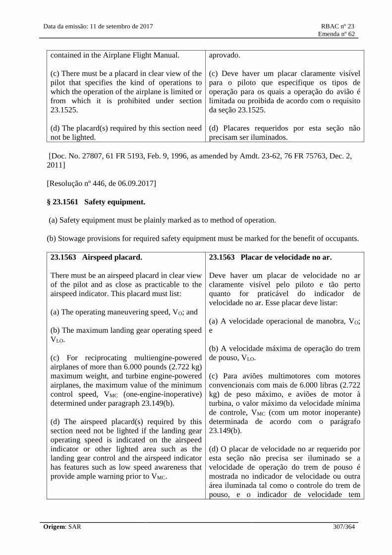
Data da emissão: 11 de setembro de 2017 RBAC nº 23
Emenda nº 62
Origem: SAR 307/364
contained in the Airplane Flight Manual.
(c) There must be a placard in clear view of the
pilot that specifies the kind of operations to
which the operation of the airplane is limited or
from which it is prohibited under section
23.1525.
(d) The placard(s) required by this section need
not be lighted.
aprovado.
(c) Deve haver um placar claramente visível
para o piloto que especifique os tipos de
operação para os quais a operação do avião é
limitada ou proibida de acordo com o requisito
da seção 23.1525.
(d) Placares requeridos por esta seção não
precisam ser iluminados.
[Doc. No. 27807, 61 FR 5193, Feb. 9, 1996, as amended by Amdt. 23-62, 76 FR 75763, Dec. 2,
2011]
[Resolução nº 446, de 06.09.2017]
§ 23.1561 Safety equipment.
(a) Safety equipment must be plainly marked as to method of operation.
(b) Stowage provisions for required safety equipment must be marked for the benefit of occupants.
23.1563 Airspeed placard.
There must be an airspeed placard in clear view
of the pilot and as close as practicable to the
airspeed indicator. This placard must list:
(a) The operating maneuvering speed, VO; and
(b) The maximum landing gear operating speed
VLO.
(c) For reciprocating multiengine-powered
airplanes of more than 6.000 pounds (2.722 kg)
maximum weight, and turbine engine-powered
airplanes, the maximum value of the minimum
control speed, VMC (one-engine-inoperative)
determined under paragraph 23.149(b).
(d) The airspeed placard(s) required by this
section need not be lighted if the landing gear
operating speed is indicated on the airspeed
indicator or other lighted area such as the
landing gear control and the airspeed indicator
has features such as low speed awareness that
provide ample warning prior to VMC.
23.1563 Placar de velocidade no ar.
Deve haver um placar de velocidade no ar
claramente visível pelo piloto e tão perto
quanto for praticável do indicador de
velocidade no ar. Esse placar deve listar:
(a) A velocidade operacional de manobra, VO;
e
(b) A velocidade máxima de operação do trem
de pouso, VLO.
(c) Para aviões multimotores com motores
convencionais com mais de 6.000 libras (2.722
kg) de peso máximo, e aviões de motor à
turbina, o valor máximo da velocidade mínima
de controle, VMC (com um motor inoperante)
determinada de acordo com o parágrafo
23.149(b).
(d) O placar de velocidade no ar requerido por
esta seção não precisa ser iluminado se a
velocidade de operação do trem de pouso é
mostrada no indicador de velocidade ou outra
área iluminada tal como o controle do trem de
pouso, e o indicador de velocidade tem

Data da emissão: 11 de setembro de 2017 RBAC nº 23
Emenda nº 62
Origem: SAR 308/364
funcionalidades como alerta de baixa
velocidade que provê amplo alerta antes da
VMC.
[[Amdt. 23-7, 34 FR 13097, Aug. 13, 1969, as amended by Amdt. 23-45, 58 FR 42166, Aug. 6,
1993; Amdt. 23-50, 61 FR 5193, Feb. 9, 1996; Amdt. 23-62, 76 FR 75763, Dec. 2, 2011]
[Resolução nº 446, de 06.09.2017]
23.1567 Flight maneuver placard.
(a) For normal category airplanes, there must
be a placard in front of and in clear view of the
pilot stating: “No acrobatic maneuvers,
including spins, approved.”
(b) For utility category airplanes, there must
be:
(1) A placard in clear view of the pilot stating:
“Acrobatic maneuvers are limited to the
following ___________;” (list approved
maneuvers and the recommended entry speed
for each); and
(2) For those airplanes that do not meet the spin
requirements for acrobatic category airplanes,
an additional placard in clear view of the pilot
stating: “Spins Prohibited.”
(c) For acrobatic category airplanes, there must
be a placard in clear view of the pilot listing the
approved acrobatic maneuvers and the
recommended entry airspeed for each. If
inverted flight maneuvers are not approved, the
placard must bear a notation to this effect.
(d) For acrobatic category airplanes and utility
category airplanes approved for spinning, there
must be a placard in clear view of the pilot:
(1) Listing the control actions for recovery
from spinning maneuvers; and
(2) Stating that recovery must be initiated when
spiral characteristics appear, or after not more
than six turns or not more than any greater
number of turns for which the airplane has
23.1567 Placar de manobras em voo.
(a) Para aviões da categoria normal, deve
existir um placar na frente do piloto e com
visão desobstruída, informando: "Nenhuma
manobra acrobática, inclusive parafuso, é
aprovada".
(b) Para aviões da categoria utilidade, deve
existir:
(1) Um placar claramente visível pelo piloto
informando: "Manobras acrobáticas são
limitadas às seguintes ___________;” (lista de
manobras aprovadas e velocidade de entrada
recomendada para cada uma delas); e
(2) Para aqueles aviões que não cumprem os
requisitos de parafuso dos aviões da categoria
acrobática, um placar adicional com visão
desobstruída pelo piloto informando:
“Proibidos parafusos".
(c) Para aviões da categoria acrobática, deve
haver um placar claramente visível pelo piloto
listando as manobras acrobáticas aprovadas e a
velocidade de entrada recomendada para cada
uma delas. Se não são aprovadas manobras de
voo invertido, o placar deve trazer uma
informação neste sentido.
(d) Para aviões da categoria acrobática e aviões
da categoria utilidade aprovados para parafuso,
deve haver um placar claramente visível pelo
piloto:
(1) Listando as ações nos comandos para
recuperação das manobras de parafuso; e
(2) Informando que a recuperação deve ser

Data da emissão: 11 de setembro de 2017 RBAC nº 23
Emenda nº 62
Origem: SAR 309/364
been certificated.
(e) The placard(s) required by this section need
not be lighted.
iniciada quando aparecerem características de
espiral, ou após não mais que seis voltas ou não
mais que qualquer número maior de voltas para
o qual o avião tenha sido certificado.
(e) Os placares requeridos por esta seção não
precisam ser iluminados.
[Doc. No. 4080, 29 FR 17955, Dec. 18, 1964; 30 FR 258, Jan. 9, 1965, as amended by Amdt. 23-
13, 37 FR 20023, Sept. 23, 1972; Amdt. 23-21, 43 FR 2319, Jan. 16, 1978; Amdt. 23-50, 61 FR
5193, Feb. 9, 1996; Amdt. 23-62, 76 FR 75763, Dec. 2, 2011]
[Resolução nº 446, de 06.09.2017]
Airplane Flight Manual and Approved Manual Material
§ 23.1581 General.
(a) Furnishing information. An Airplane Flight Manual must be furnished with each airplane, and it
must contain the following:
(1) Information required by §§23.1583 through 23.1589.
(2) Other information that is necessary for safe operation because of design, operating, or handling
characteristics.
(3) Further information necessary to comply with the relevant operating rules.
(b) Approved information. (1) Except as provided in paragraph (b)(2) of this section, each part of
the Airplane Flight Manual containing information prescribed in §§23.1583 through 23.1589 must
be approved, segregated, identified and clearly distinguished from each unapproved part of that
Airplane Flight Manual.
(2) The requirements of paragraph (b)(1) of this section do not apply to reciprocating engine-
powered airplanes of 6,000 pounds or less maximum weight, if the following is met:
(i) Each part of the Airplane Flight Manual containing information prescribed in §23.1583 must be
limited to such information, and must be approved, identified, and clearly distinguished from each
other part of the Airplane Flight Manual.
(ii) The information prescribed in §§23.1585 through 23.1589 must be determined in accordance
with the applicable requirements of this part and presented in its entirety in a manner acceptable to
the Administrator.
(3) Each page of the Airplane Flight Manual containing information prescribed in this section must
be of a type that is not easily erased, disfigured, or misplaced, and is capable of being inserted in a
manual provided by the applicant, or in a folder, or in any other permanent binder.
(c) The units used in the Airplane Flight Manual must be the same as those marked on the
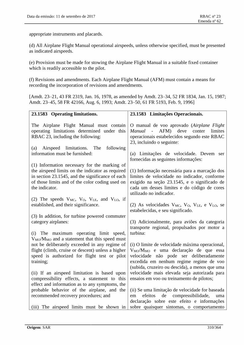
Data da emissão: 11 de setembro de 2017 RBAC nº 23
Emenda nº 62
Origem: SAR 310/364
appropriate instruments and placards.
(d) All Airplane Flight Manual operational airspeeds, unless otherwise specified, must be presented
as indicated airspeeds.
(e) Provision must be made for stowing the Airplane Flight Manual in a suitable fixed container
which is readily accessible to the pilot.
(f) Revisions and amendments. Each Airplane Flight Manual (AFM) must contain a means for
recording the incorporation of revisions and amendments.
[Amdt. 23–21, 43 FR 2319, Jan. 16, 1978, as amended by Amdt. 23–34, 52 FR 1834, Jan. 15, 1987;
Amdt. 23–45, 58 FR 42166, Aug. 6, 1993; Amdt. 23–50, 61 FR 5193, Feb. 9, 1996]
23.1583 Operating limitations.
The Airplane Flight Manual must contain
operating limitations determined under this
RBAC 23, including the following:
(a) Airspeed limitations. The following
information must be furnished:
(1) Information necessary for the marking of
the airspeed limits on the indicator as required
in section 23.1545, and the significance of each
of those limits and of the color coding used on
the indicator.
(2) The speeds VMC, VO, VLE, and VLO, if
established, and their significance.
(3) In addition, for turbine powered commuter
category airplanes:
(i) The maximum operating limit speed,
VMO/MMO and a statement that this speed must
not be deliberately exceeded in any regime of
flight (climb, cruise or descent) unless a higher
speed is authorized for flight test or pilot
training;
(ii) If an airspeed limitation is based upon
compressibility effects, a statement to this
effect and information as to any symptoms, the
probable behavior of the airplane, and the
recommended recovery procedures; and
(iii) The airspeed limits must be shown in
23.1583 Limitações Operacionais.
O manual de voo aprovado (Airplane Flight
Manual - AFM) deve conter limites
operacionais estabelecidos segundo este RBAC
23, incluindo o seguinte:
(a) Limitações de velocidade. Devem ser
fornecidas as seguintes informações:
(1) Informação necessária para a marcação dos
limites de velocidade no indicador, conforme
exigido na seção 23.1545, e o significado de
cada um desses limites e do código de cores
utilizado no indicador.
(2) As velocidades VMC, VO, VLE, e VLO, se
estabelecidas, e seu significado.
(3) Adicionalmente, para aviões da categoria
transporte regional, propulsados por motor a
turbina:
(i) O limite de velocidade máxima operacional,
VMO/MMO e uma declaração de que essa
velocidade não pode ser deliberadamente
excedida em nenhum regime regime de voo
(subida, cruzeiro ou descida), a menos que uma
velocidade mais elevada seja autorizada para
ensaios em voo ou treinamento de pilotos;
(ii) Se uma limitação de velocidade for baseada
em efeitos de compressibilidade, uma
declaração sobre este efeito e informações
sobre quaisquer sintomas, o comportamento

Data da emissão: 11 de setembro de 2017 RBAC nº 23
Emenda nº 62
Origem: SAR 311/364
terms of VMO/MMO instead of VNO and VNE.
(b) Powerplant limitations. The following
information must be furnished:
(1) Limitations required by section 23.1521.
(2) Explanation of the limitations, when
appropriate.
(3) Information necessary for marking the
instruments required by sections 23.1549
through 23.1553.
(c) Weight. The airplane flight manual must
include:
(1) The maximum weight; and
(2) The maximum landing weight, if the design
landing weight selected by the applicant is less
than the maximum weight.
(3) For each of the following normal, utility,
and acrobatic category airplanes: (1)
reciprocating engine-powered airplanes of
more than 6.000 pounds (2.722 kg) maximum
weight, (2) single-engine turbines, and (3)
multiengine turbines of 6.000 pounds (2.722
kg) or less maximum weight, performance
operating limitations as follows:
(i) The maximum takeoff weight for each
airport altitude and ambient temperature within
the range selected by the applicant at which the
airplane complies with the climb requirements
of paragraphs 23.63(c)(1)(i), (c)(2)(i), or
(c)(3)(i), as appropriate.
(ii) The maximum landing weight for each
airport altitude and ambient temperature within
the range selected by the applicant at which the
airplane complies with the climb requirements
of paragraphs 23.63(c)(1)(ii), (c)(2)(ii), or
(c)(3)(ii), as appropriate.
(4) For normal, utility, and acrobatic category
multiengine turbines over 6.000 pounds (2.722
kg) and commuter category airplanes, the
provável do avião, e os procedimentos de
recuperação recomendados; e
(iii) Os limites de velocidade devem ser
exibidos em termos de VMO/MMO, em vez de
VNO e VNE.
(b) Limitações de grupo motopropulsor.
Devem ser fornecidas as seguintes
informações:
(1) Limitações exigidas pela seção 23.1521.
(2) Explicação das limitações, quando
apropriado.
(3) Informações necessárias para marcar os
instrumentos exigidas pelas seções 23.1549 ao
23.1553.
(c) Peso. O manual de voo aprovado deve
incluir:
(1) O peso máximo; e
(2) O peso máximo de pouso, se o peso de
pouso de projeto selecionado pelo requerente
for menor que o peso máximo.
(3) Para todos os seguintes aviões das
categorias normal, utilidade e acrobática: (1)
aviões propulsados a motor convencional com
peso máximo maior do que de 6.000 libras
(2.722 kg), (2) aviões propulsados por um
motor a turbina, e (3) aviões multimotores
propulsados à turbina com 6.000 libras (2.722
kg) ou menos de peso máximo, as limitações
operacionais de desempenho da seguinte
forma:
(i) O peso máximo de decolagem para cada
altitude de aeródromo e temperatura ambiente,
no intervalo selecionado pelo requerente, no
qual o avião cumpre com os requisitos de
subida do parágrafos 23.63(c)(1)(i), (c)(2)(i),
ou (c)(3)(i), como apropriado.
(ii) O peso máximo de pouso para cada altitude
de aeródromo e temperatura ambiente, no
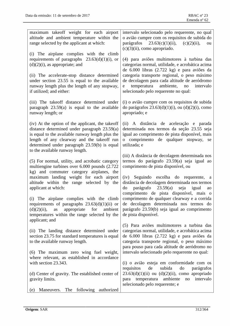
Data da emissão: 11 de setembro de 2017 RBAC nº 23
Emenda nº 62
Origem: SAR 312/364
maximum takeoff weight for each airport
altitude and ambient temperature within the
range selected by the applicant at which:
(i) The airplane complies with the climb
requirements of paragraphs 23.63(d)(1)(i), or
(d)(2)(i), as appropriate; and
(ii) The accelerate-stop distance determined
under section 23.55 is equal to the available
runway length plus the length of any stopway,
if utilized; and either:
(iii) The takeoff distance determined under
paragraph 23.59(a) is equal to the available
runway length; or
(iv) At the option of the applicant, the takeoff
distance determined under paragraph 23.59(a)
is equal to the available runway length plus the
length of any clearway and the takeoff run
determined under paragraph 23.59(b) is equal
to the available runway length.
(5) For normal, utility, and acrobatic category
multiengine turbines over 6.000 pounds (2.722
kg) and commuter category airplanes, the
maximum landing weight for each airport
altitude within the range selected by the
applicant at which:
(i) The airplane complies with the climb
requirements of paragraphs 23.63(d)(1)(ii) or
(d)(2)(ii), as appropriate for ambient
temperatures within the range selected by the
applicant; and
(ii) The landing distance determined under
section 23.75 for standard temperatures is equal
to the available runway length.
(6) The maximum zero wing fuel weight,
where relevant, as established in accordance
with section 23.343.
(d) Center of gravity. The established center of
gravity limits.
(e) Maneuvers. The following authorized
intervalo selecionado pelo requerente, no qual
o avião cumpre com os requisitos de subida do
parágrafos 23.63(c)(1)(ii), (c)(2)(ii), ou
(c)(3)(ii), como apropriado.
(4) para aviões multimotores à turbina das
categorias normal, utilidade, e acrobática acima
de 6.000 libras (2.722 kg) e para aviões da
categoria transporte regional, o peso máximo
de decolagem para cada altitude de aeródromo
e temperatura ambiente, no intervalo
selecionado pelo requerente no qual:
(i) o avião cumpre com os requisitos de subida
do parágrafos 23.63(d)(1)(i), ou (d)(2)(i), como
apropriado; e
(ii) A distância de aceleração e parada
determinada nos termos da seção 23.55 seja
igual ao comprimento de pista disponível, mais
o comprimento de qualquer stopway, se
utilizada; e
(iii) A distância de decolagem determinada nos
termos do parágrafo 23.59(a) seja igual ao
comprimento de pista disponível, ou
(iv) Seguindo escolha do requerente, a
distância de decolagem determinada nos termos
do parágrafo 23.59(a) seja igual ao
comprimento de pista disponível, mais o
comprimento de qualquer clearway e a corrida
de decolagem determinada nos termos do
parágrafo 23.59(b) seja igual ao comprimento
de pista disponível.
(5) Para aviões multimotores a turbina das
categorias normal, utilidade, e acrobática acima
de 6.000 libras (2.722 kg) e para aviões da
categoria transporte regional, o peso máximo
para pouso para cada altitude de aeródromo no
intervalo selecionado pelo requerente no qual:
(i) o avião esteja em conformidade com os
requisitos de subida do parágrafos
23.63(d)(1)(ii) ou (d)(2)(ii), como apropriado
para temperatura ambiente no intervalo
selecionado pelo requerente; e

Data da emissão: 11 de setembro de 2017 RBAC nº 23
Emenda nº 62
Origem: SAR 313/364
maneuvers, appropriate airspeed limitations,
and unauthorized maneuvers, as prescribed in
this section.
(1) Normal category airplanes. No acrobatic
maneuvers, including spins, are authorized.
(2) Utility category airplanes. A list of
authorized maneuvers demonstrated in the type
flight tests, together with recommended entry
speeds and any other associated limitations. No
other maneuver is authorized.
(3) Acrobatic category airplanes. A list of
approved flight maneuvers demonstrated in the
type flight tests, together with recommended
entry speeds and any other associated
limitations.
(4) Acrobatic category airplanes and utility
category airplanes approved for spinning. Spin
recovery procedure established to show
compliance with paragraph 23.221(c).
(5) Commuter category airplanes. Maneuvers
are limited to any maneuver incident to normal
flying, stalls, (except whip stalls) and steep
turns in which the angle of bank is not more
than 60 degrees.
(f) Maneuver load factor. The positive limit
load factors in g's, and, in addition, the
negative limit load factor for acrobatic category
airplanes.
(g) Minimum flight crew. The number and
functions of the minimum flight crew
determined under section 23.1523.
(h) Kinds of operation. A list of the kinds of
operation to which the airplane is limited or
from which it is prohibited under section
23.1525, and also a list of installed equipment
that affects any operating limitation and
identification as to the equipment's required
operational status for the kinds of operation for
which approval has been given.
(i) Maximum operating altitude. The maximum
(ii) A distância de pouso determinada nos
termos da seção 23.75 para temperaturas
padrão seja igual ao comprimento de pista
disponível.
(6) O peso máximo com zero combustível na
asa, quando relevante, conforme estabelecido
de acordo com a seção 23.343.
(d) Centro de gravidade. Os limites
estabelecidos para o centro de gravidade.
(e) Manobras. As seguintes manobras
autorizadas, limitações adequadas de
velocidade e manobras não autorizadas,
conforme prescrito nesta seção.
(1) aviões da categoria normal. Não estão
autorizadas manobra acrobática, incluindo
parafusos.
(2) aviões da categoria utilidade. Uma lista de
manobras autorizadas demonstradas nos
ensaios em voo de certificação, juntamente
com velocidades de entrada recomendadas e
quaisquer outras limitações associadas.
Nenhuma outra manobra é autorizada.
(3) aviões da categoria acrobática. Uma lista de
manobras de voo aprovadas demonstradas nos
ensaios em voo de certificação, juntamente
com velocidades de entrada recomendadas e
quaisquer outras limitações associadas.
(4) aviões da categoria acrobática e aviões da
categoria utilidade aprovados para parafuso.
Procedimento de recuperação de parafuso
estabelecido para demonstrar cumprimento
com o parágrafo 23.221(c).
(5) aviões da categoria transporte regional.
Manobras estão limitadas a qualquer manobra
incidente para voo normal, estóis, (exceto
estóis whip) e curvas acentuadas nas quais o
ângulo de inclinação não seja superior a 60
graus.
(f) Fator de carga de manobra. Os limites
positivos de fator de carga em g (aceleração da
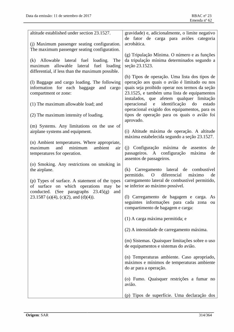
Data da emissão: 11 de setembro de 2017 RBAC nº 23
Emenda nº 62
Origem: SAR 314/364
altitude established under section 23.1527.
(j) Maximum passenger seating configuration.
The maximum passenger seating configuration.
(k) Allowable lateral fuel loading. The
maximum allowable lateral fuel loading
differential, if less than the maximum possible.
(l) Baggage and cargo loading. The following
information for each baggage and cargo
compartment or zone:
(1) The maximum allowable load; and
(2) The maximum intensity of loading.
(m) Systems. Any limitations on the use of
airplane systems and equipment.
(n) Ambient temperatures. Where appropriate,
maximum and minimum ambient air
temperatures for operation.
(o) Smoking. Any restrictions on smoking in
the airplane.
(p) Types of surface. A statement of the types
of surface on which operations may be
conducted. (See paragraphs 23.45(g) and
23.1587 (a)(4), (c)(2), and (d)(4)).
gravidade) e, adicionalmente, o limite negativo
de fator de carga para aviões categoria
acrobática.
(g) Tripulação Mínima. O número e as funções
da tripulação mínima determinados segundo a
seção 23.1523.
(h) Tipos de operação. Uma lista dos tipos de
operação aos quais o avião é limitado ou nos
quais seja proibido operar nos termos da seção
23.1525, e também uma lista de equipamentos
instalados, que afetem qualquer limitação
operacional e identificação do estado
operacional exigido dos equipamentos, para os
tipos de operação para os quais o avião foi
aprovado.
(i) Altitude máxima de operação. A altitude
máxima estabelecida segundo a seção 23.1527.
(j) Configuração máxima de assentos de
passageiros. A configuração máxima de
assentos de passageiros.
(k) Carregamento lateral de combustível
permitido. O diferencial máximo de
carregamento lateral de combustível permitido,
se inferior ao máximo possível.
(l) Carregamento de bagagem e carga. As
seguintes informações para cada zona ou
compartimento de bagagem e carga:
(1) A carga máxima permitida; e
(2) A intensidade de carregamento máxima.
(m) Sistemas. Quaisquer limitações sobre o uso
de equipamentos e sistemas do avião.
(n) Temperaturas ambiente. Caso apropriado,
máximos e mínimos de temperaturas ambiente
do ar para a operação.
(o) Fumo. Quaisquer restrições a fumar no
avião.
(p) Tipos de superfície. Uma declaração dos
Data da emissão: 11 de setembro de 2017 RBAC nº 23
Emenda nº 62
Origem: SAR 315/364
tipos de superfície nas quais as operações
podem ser realizadas. (Veja os parágrafos
23.45(g) e os 23.1587(a)(4), (c)(2), e (d)(4)).
[Doc. No. 4080, 29 FR 17955, Dec. 18, 1964, as amended by Amdt. 23-7, 34 FR 13097, Aug. 13,
1969; Amdt. 23-10, 36 FR 2864, Feb. 11, 1971; Amdt. 23-21, 43 FR 2320, Jan. 16, 1978; Amdt.
23-23, 43 FR 50594, Oct. 30, 1978; Amdt. 23-34, 52 FR 1834, Jan. 15, 1987; Amdt. 23-45, 58 FR
42166, Aug. 6, 1993; Amdt. 23-50, 61 FR 5193, Feb. 9, 1996; Amdt. 23-62, 76 FR 75763, Dec. 2,
2011]
[Resolução nº 446, de 06.09.2017]
23.1585 Operating procedures.
(a) For all airplanes, information concerning
normal, abnormal (if applicable), and
emergency procedures and other pertinent
information necessary for safe operation and
the achievement of the scheduled performance
must be furnished, including:
(1) An explanation of significant or unusual
flight or ground handling characteristics;
(2) The maximum demonstrated values of
crosswind for takeoff and landing, and
procedures and information pertinent to
operations in crosswinds;
(3) A recommended speed for flight in rough
air. This speed must be chosen to protect
against the occurrence, as a result of gusts, of
structural damage to the airplane and loss of
control (for example, stalling);
(4) Procedures for restarting any turbine engine
in flight, including the effects of altitude; and
(5) Procedures, speeds, and configuration(s) for
making a normal approach and landing, in
accordance with sections 23.73 and 23.75, and
a transition to the balked landing condition.
(6) For seaplanes and amphibians, water
handling procedures and the demonstrated
wave height.
(b) In addition to paragraph (a) of this section,
for all single-engine airplanes, the procedures,
23.1585 Procedimentos operacionais.
(a) Devem ser fornecidas, para todos os aviões,
as informações relativas a procedimentos
normais, anormais (se aplicável) e de
emergência. Também deverão ser fornecidas
outras informações pertinentes necessárias para
uma operação segura e para a realização do
desempenho previsto, incluindo:
(1) Uma explicação das características
significativas ou incomuns de voo ou
características de uso em solo;
(2) Os valores máximos de vento cruzado
demonstrados para decolagem e pouso, e os
procedimentos e informações pertinentes às
operações em vento cruzado;
(3) A velocidade recomendada para o voo em
ar turbulento. Esta velocidade deve ser
escolhida para proteger contra a ocorrência de
danos estruturais no avião e perda de controle
(por exemplo, em estóis), como resultado de
rajada;
(4) Procedimentos para nova partida no motor
para qualquer motor à turbina em voo,
incluindo os efeitos da altitude, e
(5) Procedimentos, velocidades e configurações
para executar aproximação e pouso normais, de
acordo com as seções 23.73 e 23.75, e uma
transição para condição de arremetida.
(6) Para hidroaviões e aviões anfíbios, os
procedimentos de uso na água, e a altura de

Data da emissão: 11 de setembro de 2017 RBAC nº 23
Emenda nº 62
Origem: SAR 316/364
speeds, and configuration(s) for a glide
following engine failure, in accordance with
section 23.71 and the subsequent forced
landing, must be furnished.
(c) In addition to paragraph (a) of this section,
for all multiengine airplanes, the following
information must be furnished:
(1) Procedures, speeds, and configuration(s) for
making an approach and landing with one
engine inoperative;
(2) Procedures, speeds, and configuration(s) for
making a balked landing with one engine
inoperative and the conditions under which a
balked landing can be performed safely, or a
warning against attempting a balked landing;
(3) The VSSE determined in section 23.149; and
(4) Procedures for restarting any engine in
flight including the effects of altitude.
(d) In addition to paragraphs (a) and either (b)
or (c) of this section, as appropriate, for all
normal, utility, and acrobatic category
airplanes, the following information must be
furnished:
(1) Procedures, speeds, and configuration(s) for
making a normal takeoff, in accordance with
paragraphs 23.51 (a) and (b), and 23.53 (a) and
(b), and the subsequent climb, in accordance
with section 23.65 and paragraph 23.69(a).
(2) Procedures for abandoning a takeoff due to
engine failure or other cause.
(e) In addition to paragraphs (a), (c), and (d) of
this section, for all normal, utility, and
acrobatic category multiengine airplanes, the
information must include the following:
(1) Procedures and speeds for continuing a
takeoff following engine failure and the
conditions under which takeoff can safely be
continued, or a warning against attempting to
onda demonstrada.
(b) Além do parágrafo (a) desta seção, para
todos os aviões monomotores, devem ser
fornecidos os procedimentos, velocidades e
configurações para planeio seguido a uma falha
de motor, em conformidade com a seção 23.71,
bem como o pouso forçado subsequentes.
(c) Além do parágrafo (a) desta seção, para
todos os aviões multimotores, devem ser
fornecidas as seguintes informações:
(1) Procedimentos, velocidades e configurações
para executar aproximação e pouso com um
motor inoperativo;
(2) Procedimentos, velocidades e configurações
para executar arremetida, com um motor
inoperante, e as condições nas quais uma
arremetida pode ser realizada com segurança,
ou um aviso contra a tentativa de arremetida;
(3) A VSSE determinada na seção 23.149, e
(4) Procedimentos para nova partida de
qualquer motor em voo, incluindo os efeitos da
altitude.
(d) Além dos parágrafos (a) e, ou (b) ou (c)
desta seção, conforme for apropriado, para
todos aviões categoria normal, utilidade, e
acrobática, devem ser fornecidas as seguintes
informações:
(1) Procedimentos, velocidades e configurações
para executar decolagem normal, de acordo
com os parágrafos 23.51(a) e (b), e 23.53(a) e
(b), e subida subsequente, em conformidade
com a seção 23.65 e parágrafo 23.69(a).
(2) Procedimentos para abandonar uma
decolagem devido a uma falha do motor ou
outra causa.
(e) Além dos parágrafos (a), (c), e (d) desta
seção, para todos aviões multimotores
categoria normal, utilidade e acrobática, a

Data da emissão: 11 de setembro de 2017 RBAC nº 23
Emenda nº 62
Origem: SAR 317/364
continue the takeoff.
(2) Procedures, speeds, and configurations for
continuing a climb following engine failure,
after takeoff, in accordance with section 23.67,
or enroute, in accordance with paragraph
23.69(b).
(f) In addition to paragraphs (a) and (c) of this
section, for normal, utility, and acrobatic
category multiengine jets weighing over 6.000
pounds (2.722 kg), and commuter category
airplanes, the information must include the
following:
(1) Procedures, speeds, and configuration(s) for
making a normal takeoff.
(2) Procedures and speeds for carrying out an
accelerate-stop in accordance with section
23.55.
(3) Procedures and speeds for continuing a
takeoff following engine failure in accordance
with paragraph 23.59(a)(1) and for following
the flight path determined under section 23.57
and paragraph 23.61(a).
(g) For multiengine airplanes, information
identifying each operating condition in which
the fuel system independence prescribed in
section 23.953 is necessary for safety must be
furnished, together with instructions for placing
the fuel system in a configuration used to show
compliance with that section.
(h) For each airplane showing compliance with
paragraphs 23.1353(g)(2) or (g)(3), the
operating procedures for disconnecting the
battery from its charging source must be
furnished.
(i) Information on the total quantity of usable
fuel for each fuel tank, and the effect on the
usable fuel quantity, as a result of a failure of
any pump, must be furnished.
(j) Procedures for the safe operation of the
airplane's systems and equipment, both in
informação deve incluir o seguinte:
(1) Os procedimentos e velocidades para
continuar a decolagem em seguida a uma falha
de motor e as condições nas quais a decolagem
pode ser continuada com segurança, ou um
alerta contra a tentativa de continuar a
decolagem.
(2) Procedimentos, velocidades e configurações
para continuar a subida em seguida a uma falha
do motor, de acordo com a seção 23.67, após a
decolagem, ou de acordo com o parágrafo
23.69(b), quando em rota.
(f) Além dos parágrafos (a) e (c) desta seção,
para aviões multimotores a jato das categorias
normal, utilidade, e acrobática com peso acima
de 6.000 libras (2.722 kg) e para aviões
categoria transporte regional, as informações
devem incluir o seguinte:
(1) Procedimentos, velocidades e configurações
para executar decolagem normal.
(2) Os procedimentos e velocidades para
execução de aceleração e parada em
conformidade com a seção 23.55.
(3) Os procedimentos e velocidades para
continuar a decolagem em seguida a uma falha
do motor, em conformidade com o parágrafo
23.59(a)(1), e para seguir a trajetória de voo
determinada de acordo com seção 23.57 e
parágrafo 23.61(a).
(g) Para aviões multimotores, devem ser
fornecidas informações que identifiquem cada
condição de operação na qual a independência
do sistema de combustível prevista na seção
23.953 seja necessária para a segurança, em
conjunto com as instruções para a colocar o
sistema de combustível em uma configuração
utilizada para demonstrar a cumprimento com
esta seção.
(h) Para cada avião que demonstre
cumprimento com os parágrafos 23.1353(g)(2)
ou (g)(3), devem ser fornecidos os

Data da emissão: 11 de setembro de 2017 RBAC nº 23
Emenda nº 62
Origem: SAR 318/364
normal use and in the event of malfunction,
must be furnished.
procedimentos operacionais para desconectar a
bateria de sua fonte de carregamento.
(i) Devem ser fornecidas informações sobre a
quantidade total de combustível utilizável, para
cada tanque de combustível, e o efeito na
quantidade de combustível utilizável, em caso
de mau funcionamento de qualquer bomba.
(j) Devem ser fornecidos os procedimentos
para a operação segura dos sistemas do avião e
equipamentos, tanto em uso normal como em
caso de mau funcionamento.
[Doc. No. 27807, 61 FR 5194, Feb. 9, 1996, as amended by Amdt. 23-62, 76 FR 75763, Dec. 2,
2011]
[Resolução nº 446, de 06.09.2017]
23.1587 Performance information.
Unless otherwise prescribed, performance
information must be provided over the altitude
and temperature ranges required by paragraph
23.45(b).
(a) For all airplanes, the following information
must be furnished:
(1) The stalling speeds VS0 and VS1 with the
landing gear and wing flaps retracted,
determined at maximum weight under section
23.49, and the effect on these stalling speeds of
angles of bank up to 60 degrees;
(2) The steady rate and gradient of climb with
all engines operating, determined under
paragraph 23.69(a);
(3) The landing distance, determined under
section 23.75 for each airport altitude and
standard temperature, and the type of surface
for which it is valid;
(4) The effect on landing distances of operation
on other than smooth hard surfaces, when dry,
determined under paragraph 23.45(g); and
(5) The effect on landing distances of runway
23.1587 Informações de desempenho.
Salvo indicação em contrário, as informações
de desempenho devem ser fornecidas no
intervalo de altitudes e temperaturas exigidos
pelo parágrafo 23.45(b).
(a) Devem ser fornecidas, para todos os aviões,
as seguintes informações:
(1) As velocidades de estol VS0 e VS1, com
trem de pouso e flapes recolhidos,
determinadas com o peso máximo, nos termos
da seção 23.49, e o efeito de ângulos de
inclinação de até 60 graus, sobre estas
velocidades de estol;
(2) A razão de subida estabilizada e o gradiente
de subida estabilizado, com todos os motores
operando, determinada no parágrafo 23.69(a);
(3) A distância de pouso, determinada na seção
23.75, para cada altitude e temperatura padrão
de aeródromo, e o tipo de superfície para a qual
é válida;
(4) O efeito, sobre as distâncias de pouso, da
operação outras superfícies que não sejam lisas
e duras, quando secas, determinado nos termos

Data da emissão: 11 de setembro de 2017 RBAC nº 23
Emenda nº 62
Origem: SAR 319/364
slope and 50 percent of the headwind
component and 150 percent of the tailwind
component.
(b) In addition to paragraph (a) of this section,
for all normal, utility, and acrobatic category
reciprocating engine-powered airplanes of
6.000 pounds (2.722 kg) or less maximum
weight, the steady angle of climb/descent,
determined under paragraph 23.77(a), must be
furnished.
(c) In addition to paragraphs (a) and (b) of this
section, if appropriate, for normal, utility, and
acrobatic category airplanes, the following
information must be furnished:
(1) The takeoff distance, determined under
section 23.53 and the type of surface for which
it is valid.
(2) The effect on takeoff distance of operation
on other than smooth hard surfaces, when dry,
determined under paragraph 23.45(g);
(3) The effect on takeoff distance of runway
slope and 50 percent of the headwind
component and 150 percent of the tailwind
component;
(4) For multiengine reciprocating engine-
powered airplanes of more than 6.000 pounds
(2.722 kg) maximum weight and multiengine
turbine powered airplanes, the one-engine-
inoperative takeoff climb/descent gradient,
determined under section 23.66;
(5) For multiengine airplanes, the enroute rate
and gradient of climb/descent with one engine
inoperative, determined under paragraph
23.69(b); and
(6) For single-engine airplanes, the glide
performance determined under section 23.71.
(d) In addition to paragraph (a) of this section,
for normal, utility, and acrobatic category
multiengine jets weighing over 6.000 pounds
(2.722 kg), and commuter category airplanes,
do parágrafo 23.45(g), e
(5) O efeito, sobre as distâncias de pouso, da
inclinação da pista, bem como o efeito de 50
por cento do componente de vento frontal e o
efeito de 150 por cento do componente de
vento de cauda.
(b) Além do parágrafo (a) desta seção, deve ser
fornecido, para todos os aviões categoria
normal, utilidade, e acrobática, propulsados por
motor convencional, com 6.000 libras (2.722
kg) ou menos de peso máximo, o ângulo de
subida/descida estabilizado, determinado nos
termos do parágrafo 23.77(a).
(c) Além dos parágrafos (a) e (b) desta seção,
conforme o caso, para aviões categoria normal,
utilidade, e acrobática, devem ser fornecidas as
seguintes informações:
(1) A distância de decolagem, determinada nos
termos da seção 23.53 e o tipo de superfície
para a qual ela é válida.
(2) O efeito, sobre a distância de decolagem, da
operação em outras superfícies que não sejam
lisas e duras, quando secas, determinado nos
termos do parágrafo 23.45(g);
(3) O efeito, sobre a distância de decolagem, da
inclinação da pista, bem como o efeito de 50
por cento do componente de vento frontal, e o
efeito de 150 por cento do componente de
vento de cauda;
(4) Para aviões multimotores, propulsados por
motores convencionais, com mais de 6.000
libras (2.722 kg) de peso máximo e aviões
multimotores a turbina, o gradiente de
subida/descida de decolagem, com um motor
inoperante, determinado nos termos da seção
23.66;
(5) Para aviões multimotores, a razão e o
gradiente, de subida/descida, em rota, com um
motor inoperante, determinada nos termos do
parágrafo 23.69(b), e

Data da emissão: 11 de setembro de 2017 RBAC nº 23
Emenda nº 62
Origem: SAR 320/364
the following information must be furnished:
(1) The accelerate-stop distance determined
under section 23.55;
(2) The takeoff distance determined under
paragraph 23.59(a);
(3) At the option of the applicant, the takeoff
run determined under paragraph 23.59(b);
(4) The effect on accelerate-stop distance,
takeoff distance and, if determined, takeoff run,
of operation on other than smooth hard
surfaces, when dry, determined under
paragraph 23.45(g);
(5) The effect on accelerate-stop distance,
takeoff distance, and if determined, takeoff run,
of runway slope and 50 percent of the
headwind component and 150 percent of the
tailwind component;
(6) The net takeoff flight path determined
under paragraph 23.61(b);
(7) The enroute gradient of climb/descent with
one engine inoperative, determined under
paragraph 23.69(b);
(8) The effect, on the net takeoff flight path and
on the enroute gradient of climb/descent with
one engine inoperative, of 50 percent of the
headwind component and 150 percent of the
tailwind component;
(9) Overweight landing performance
information (determined by extrapolation and
computed for the range of weights between the
maximum landing and maximum takeoff
weights) as follows:
(i) The maximum weight for each airport
altitude and ambient temperature at which the
airplane complies with the climb requirements
of paragraph 23.63(d)(2); and
(ii) The landing distance determined under
section 23.75 for each airport altitude and
(6) Para aviões monomotor, o desempenho de
planeio, determinado nos termos da seção
23.71.
(d) Em adição ao parágrafo (a) desta seção,
para aviações multimotores a jato das
categorias normal, utilidade, e acrobática com
peso acima de 6.000 libras (2.722 kg) e para
aviões dos aviões categoria transporte regional,
devem ser fornecidas as seguintes informações:
(1) A distância de aceleração e parada,
determinada nos termos da seção 23.55;
(2) A distância de decolagem, determinada nos
termos do parágrafo 23.59(a);
(3) Como opção do requerente, a corrida de
decolagem, determinada nos termos do
parágrafo 23.59(b);
(4) O efeito sobre a distância de aceleração e
parada, distância de decolagem e, se
determinada, corrida de decolagem, da
operação em outras superfícies que não sejam
lisas e duras, quando seco, determinado nos
termos do parágrafo 23.45(g);
(5) O efeito sobre a distância de aceleração e
parada, distância de decolagem, e se
determinada, corrida de decolagem, da
inclinação da pista, bem como o efeito de 50
por cento do componente de vento frontal e o
efeito de 150 por cento do componente de
vento de cauda;
(6) A trajetória de voo líquida na decolagem,
determinada nos termos do parágrafo 23.61(b);
(7) O gradiente de subida/descida, em rota,
com um motor inoperante, determinado nos
termos do parágrafo 23.69(b);
(8) O efeito, na trajetória de voo líquida na
decolagem e no gradiente de subida/descida,
em rota, com um motor inoperante, de 50 por
cento do componente de vento frontal bem
como o efeito de 150 por cento do componente

Data da emissão: 11 de setembro de 2017 RBAC nº 23
Emenda nº 62
Origem: SAR 321/364
standard temperature.
(10) The relationship between IAS and CAS
determined in accordance with paragraphs
23.1323 (b) and (c).
(11) The altimeter system calibration required
by paragraph 23.1325(e).
de vento de cauda;
(9) informações sobre o desempenho de pouso
com excesso de peso (determinado por
extrapolação e calculado para a faixa de pesos
entre o peso máximo de pouso e peso máximo
de decolagem) da seguinte forma:
(i) O peso máximo para cada altitude e
temperatura ambiente de aeródromo na qual o
avião cumpra com os requisitos de subida do
parágrafo 23.63(d)(2), e
(ii) A distância de pouso, determinada nos
termos da seção 23.75, para cada altitude de
aeródromo e temperatura padrão.
(10) A relação entre as IAS e CAS determinado
de acordo com os parágrafos 23.1323(b) e (c).
(11) O sistema de calibração do altímetro
exigido pelo parágrafo 23.1325(e).
[Doc. No. 27807, 61 FR 5194, Feb. 9, 1996, as amended by Amdt. 23-62, 76 FR 75763, Dec. 2,
2011]
[Resolução nº 446, de 06.09.2017]
§ 23.1589 Loading information.
The following loading information must be furnished:
(a) The weight and location of each item of equipment that can be easily removed, relocated, or
replaced and that is installed when the airplane was weighed under the requirement of §23.25.
(b) Appropriate loading instructions for each possible loading condition between the maximum and
minimum weights established under §23.25, to facilitate the center of gravity remaining within the
limits established under §23.23.
[Doc. No. 4080, 29 FR 17955, Dec. 18, 1964, as amended by Amdt. 23–45, 58 FR 42167, Aug. 6,
1993; Amdt. 23–50, 61 FR 5195, Feb. 9, 1996]
Appendix A to Part 23—Simplified Design Load Criteria
A23.1 General.
(a) The design load criteria in this appendix are an approved equivalent of those in §§23.321
through 23.459 of this subchapter for an airplane having a maximum weight of 6,000 pounds or less
and the following configuration:

Data da emissão: 11 de setembro de 2017 RBAC nº 23
Emenda nº 62
Origem: SAR 322/364
(1) A single engine excluding turbine powerplants;
(2) A main wing located closer to the airplane's center of gravity than to the aft, fuselage-mounted,
empennage;
(3) A main wing that contains a quarter-chord sweep angle of not more than 15 degrees fore or aft;
(4) A main wing that is equipped with trailing-edge controls (ailerons or flaps, or both);
(5) A main wing aspect ratio not greater than 7;
(6) A horizontal tail aspect ratio not greater than 4;
(7) A horizontal tail volume coefficient not less than 0.34;
(8) A vertical tail aspect ratio not greater than 2;
(9) A vertical tail platform area not greater than 10 percent of the wing platform area; and
(10) Symmetrical airfoils must be used in both the horizontal and vertical tail designs.
(b) Appendix A criteria may not be used on any airplane configuration that contains any of the
following design features:
(1) Canard, tandem-wing, close-coupled, or tailless arrangements of the lifting surfaces;
(2) Biplane or multiplane wing arrangements;
(3) T-tail, V-tail, or cruciform-tail (+) arrangements;
(4) Highly-swept wing platform (more than 15-degrees of sweep at the quarter-chord), delta
planforms, or slatted lifting surfaces; or
(5) Winglets or other wing tip devices, or outboard fins.
A23.3 Special symbols.
n 1=Airplane Positive Maneuvering Limit Load Factor.
n 2=Airplane Negative Maneuvering Limit Load Factor.
n 3=Airplane Positive Gust Limit Load Factor at V C.
n 4=Airplane Negative Gust Limit Load Factor at V C.
n flap=Airplane Positive Limit Load Factor With Flaps Fully Extended at V F.

Data da emissão: 11 de setembro de 2017 RBAC nº 23
Emenda nº 62
Origem: SAR 323/364
A23.5 Certification in more than one category.
The criteria in this appendix may be used for certification in the normal, utility, and acrobatic
categories, or in any combination of these categories. If certification in more than one category is
desired, the design category weights must be selected to make the term n 1 W constant for all
categories or greater for one desired category than for others. The wings and control surfaces
(including wing flaps and tabs) need only be investigated for the maximum value of n 1 W, or for
the category corresponding to the maximum design weight, where n 1 W is constant. If the
acrobatic category is selected, a special unsymmetrical flight load investigation in accordance with
paragraphs A23.9(c)(2) and A23.11(c)(2) of this appendix must be completed. The wing, wing
carrythrough, and the horizontal tail structures must be checked for this condition. The basic
fuselage structure need only be investigated for the highest load factor design category selected.
The local supporting structure for dead weight items need only be designed for the highest load
factor imposed when the particular items are installed in the airplane. The engine mount, however,
must be designed for a higher side load factor, if certification in the acrobatic category is desired,
than that required for certification in the normal and utility categories. When designing for landing
loads, the landing gear and the airplane as a whole need only be investigated for the category
corresponding to the maximum design weight. These simplifications apply to single-engine aircraft
of conventional types for which experience is available, and the Administrator may require
additional investigations for aircraft with unusual design features.
A23.7 Flight loads.
(a) Each flight load may be considered independent of altitude and, except for the local supporting
structure for dead weight items, only the maximum design weight conditions must be investigated.
(b) Table 1 and figures 3 and 4 of this appendix must be used to determine values of n 1, n 2, n 3,
and n 4, corresponding to the maximum design weights in the desired categories.
(c) Figures 1 and 2 of this appendix must be used to determine values of n 3and n 4corresponding to
the minimum flying weights in the desired categories, and, if these load factors are greater than the
load factors at the design weight, the supporting structure for dead weight items must be
substantiated for the resulting higher load factors.
(d) Each specified wing and tail loading is independent of the center of gravity range. The applicant,
however, must select a c.g. range, and the basic fuselage structure must be investigated for the most
adverse dead weight loading conditions for the c.g. range selected.
(e) The following loads and loading conditions are the minimums for which strength must be
provided in the structure:
(1) Airplane equilibrium. The aerodynamic wing loads may be considered to act normal to the

Data da emissão: 11 de setembro de 2017 RBAC nº 23
Emenda nº 62
Origem: SAR 324/364
relative wind, and to have a magnitude of 1.05 times the airplane normal loads (as determined from
paragraphs A23.9 (b) and (c) of this appendix) for the positive flight conditions and a magnitude
equal to the airplane normal loads for the negative conditions. Each chordwise and normal
component of this wing load must be considered.
(2) Minimum design airspeeds. The minimum design airspeeds may be chosen by the applicant
except that they may not be less than the minimum speeds found by using figure 3 of this appendix.
In addition, V Cminneed not exceed values of 0.9 V Hactually obtained at sea level for the lowest
design weight category for which certification is desired. In computing these minimum design
airspeeds, n 1may not be less than 3.8.
(3) Flight load factor. The limit flight load factors specified in Table 1 of this appendix represent
the ratio of the aerodynamic force component (acting normal to the assumed longitudinal axis of the
airplane) to the weight of the airplane. A positive flight load factor is an aerodynamic force acting
upward, with respect to the airplane.
A23.9 Flight conditions.
(a) General. Each design condition in paragraphs (b) and (c) of this section must be used to assure
sufficient strength for each condition of speed and load factor on or within the boundary of a V−n
diagram for the airplane similar to the diagram in figure 4 of this appendix. This diagram must also
be used to determine the airplane structural operating limitations as specified in §§23.1501(c)
through 23.1513 and §23.1519.
(b) Symmetrical flight conditions. The airplane must be designed for symmetrical flight conditions
as follows:
(1) The airplane must be designed for at least the four basic flight conditions, “A”, “D”, “E”, and
“G” as noted on the flight envelope of figure 4 of this appendix. In addition, the following
requirements apply:
(i) The design limit flight load factors corresponding to conditions “D” and “E” of figure 4 must be
at least as great as those specified in Table 1 and figure 4 of this appendix, and the design speed for
these conditions must be at least equal to the value of V Dfound from figure 3 of this appendix.
(ii) For conditions “A” and “G” of figure 4, the load factors must correspond to those specified in
Table 1 of this appendix, and the design speeds must be computed using these load factors with the
maximum static lift coefficient C NAdetermined by the applicant. However, in the absence of more
precise computations, these latter conditions may be based on a value of C NA=±1.35 and the
design speed for condition “A” may be less than V Amin.
(iii) Conditions “C” and “F” of figure 4 need only be investigated when n 3W/S or n 4W/S are
greater than n 1W/S or n 2W/S of this appendix, respectively.
(2) If flaps or other high lift devices intended for use at the relatively low airspeed of approach,
landing, and takeoff, are installed, the airplane must be designed for the two flight conditions
corresponding to the values of limit flap-down factors specified in Table 1 of this appendix with the
flaps fully extended at not less than the design flap speed V Fminfrom figure 3 of this appendix.

Data da emissão: 11 de setembro de 2017 RBAC nº 23
Emenda nº 62
Origem: SAR 325/364
(c) Unsymmetrical flight conditions. Each affected structure must be designed for unsymmetrical
loadings as follows:
(1) The aft fuselage-to-wing attachment must be designed for the critical vertical surface load
determined in accordance with paragraph SA23.11(c)(1) and (2) of this appendix.
(2) The wing and wing carry-through structures must be designed for 100 percent of condition “A”
loading on one side of the plane of symmetry and 70 percent on the opposite side for certification in
the normal and utility categories, or 60 percent on the opposite side for certification in the acrobatic
category.
(3) The wing and wing carry-through structures must be designed for the loads resulting from a
combination of 75 percent of the positive maneuvering wing loading on both sides of the plane of
symmetry and the maximum wing torsion resulting from aileron displacement. The effect of aileron
displacement on wing torsion at V Cor V Ausing the basic airfoil moment coefficient modified over
the aileron portion of the span, must be computed as follows:
(i) Cm=Cm +0.01δμ(up aileron side) wing basic airfoil.
(ii) Cm=Cm −0.01δμ(down aileron side) wing basic airfoil, whereδμis the up aileron deflection andδd
is the down aileron deflection.
(4) Δ critical, which is the sum ofδμ+δd must be computed as follows:
(i) Compute Δα and Δbfrom the formulas:
Where Δp=the maximum total deflection (sum of both aileron deflections) at V Awith V A, V
C,and V Ddescribed in subparagraph (2) of §23.7(e) of this appendix.
(ii) Compute K from the formula:
whereδαis the down aileron deflection corresponding toΔα,andδb is the down aileron deflection
corresponding toΔb as computed in step (i).
(iii) If K is less than 1.0,Δαis Δ critical and must be used to determineδuandδ d. In this case, V Cis
the critical speed which must be used in computing the wing torsion loads over the aileron span.
(iv) If K is equal to or greater than 1.0,Δbis Δ critical and must be used to determineδuandδd.In this
case, V dis the critical speed which must be used in computing the wing torsion loads over the

Data da emissão: 11 de setembro de 2017 RBAC nº 23
Emenda nº 62
Origem: SAR 326/364
aileron span.
(d) Supplementary conditions; rear lift truss; engine torque; side load on engine mount. Each of the
following supplementary conditions must be investigated:
(1) In designing the rear lift truss, the special condition specified in §23.369 may be investigated
instead of condition “G” of figure 4 of this appendix. If this is done, and if certification in more than
one category is desired, the value of W/S used in the formula appearing in §23.369 must be that for
the category corresponding to the maximum gross weight.
(2) Each engine mount and its supporting structures must be designed for the maximum limit torque
corresponding to METO power and propeller speed acting simultaneously with the limit loads
resulting from the maximum positive maneuvering flight load factor n 1. The limit torque must be
obtained by multiplying the mean torque by a factor of 1.33 for engines with five or more cylinders.
For 4, 3, and 2 cylinder engines, the factor must be 2, 3, and 4, respectively.
(3) Each engine mount and its supporting structure must be designed for the loads resulting from a
lateral limit load factor of not less than 1.47 for the normal and utility categories, or 2.0 for the
acrobatic category.
A23.11 Control surface loads.
(a) General. Each control surface load must be determined using the criteria of paragraph (b) of this
section and must lie within the simplified loadings of paragraph (c) of this section.
(b) Limit pilot forces. In each control surface loading condition described in paragraphs (c) through
(e) of this section, the airloads on the movable surfaces and the corresponding deflections need not
exceed those which could be obtained in flight by employing the maximum limit pilot forces
specified in the table in §23.397(b). If the surface loads are limited by these maximum limit pilot
forces, the tabs must either be considered to be deflected to their maximum travel in the direction
which would assist the pilot or the deflection must correspond to the maximum degree of “out of
trim” expected at the speed for the condition under consideration. The tab load, however, need not
exceed the value specified in Table 2 of this appendix.
(c) Surface loading conditions. Each surface loading condition must be investigated as follows:
(1) Simplified limit surface loadings for the horizontal tail, vertical tail, aileron, wing flaps, and trim
tabs are specified in figures 5 and 6 of this appendix.
(i) The distribution of load along the span of the surface, irrespective of the chordwise load
distribution, must be assumed proportional to the total chord, except on horn balance surfaces.
(ii) The load on the stabilizer and elevator, and the load on fin and rudder, must be distributed
chordwise as shown in figure 7 of this appendix.
(iii) In order to ensure adequate torsional strength and to account for maneuvers and gusts, the most
severe loads must be considered in association with every center of pressure position between the
leading edge and the half chord of the mean chord of the surface (stabilizer and elevator, or fin and
rudder).

Data da emissão: 11 de setembro de 2017 RBAC nº 23
Emenda nº 62
Origem: SAR 327/364
(iv) To ensure adequate strength under high leading edge loads, the most severe stabilizer and fin
loads must be further considered as being increased by 50 percent over the leading 10 percent of the
chord with the loads aft of this appropriately decreased to retain the same total load.
(v) The most severe elevator and rudder loads should be further considered as being distributed
parabolically from three times the mean loading of the surface (stabilizer and elevator, or fin and
rudder) at the leading edge of the elevator and rudder, respectively, to zero at the trailing edge
according to the equation:
Where—
P(x)=local pressure at the chordwise stations x,
c=chord length of the tail surface,
cf=chord length of the elevator and rudder respectively, and
w=average surface loading as specified in Figure A5.
(vi) The chordwise loading distribution for ailerons, wing flaps, and trim tabs are specified in Table
2 of this appendix.
(2) If certification in the acrobatic category is desired, the horizontal tail must be investigated for an
unsymmetrical load of 100 percent w on one side of the airplane centerline and 50 percent on the
other side of the airplane centerline.
(d) Outboard fins. Outboard fins must meet the requirements of §23.445.
(e) Special devices. Special devices must meet the requirements of §23.459.
A23.13 Control system loads.
(a) Primary flight controls and systems. Each primary flight control and system must be designed as
follows:
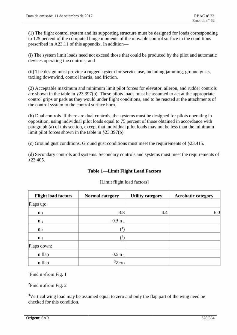
Data da emissão: 11 de setembro de 2017 RBAC nº 23
Emenda nº 62
Origem: SAR 328/364
(1) The flight control system and its supporting structure must be designed for loads corresponding
to 125 percent of the computed hinge moments of the movable control surface in the conditions
prescribed in A23.11 of this appendix. In addition—
(i) The system limit loads need not exceed those that could be produced by the pilot and automatic
devices operating the controls; and
(ii) The design must provide a rugged system for service use, including jamming, ground gusts,
taxiing downwind, control inertia, and friction.
(2) Acceptable maximum and minimum limit pilot forces for elevator, aileron, and rudder controls
are shown in the table in §23.397(b). These pilots loads must be assumed to act at the appropriate
control grips or pads as they would under flight conditions, and to be reacted at the attachments of
the control system to the control surface horn.
(b) Dual controls. If there are dual controls, the systems must be designed for pilots operating in
opposition, using individual pilot loads equal to 75 percent of those obtained in accordance with
paragraph (a) of this section, except that individual pilot loads may not be less than the minimum
limit pilot forces shown in the table in §23.397(b).
(c) Ground gust conditions. Ground gust conditions must meet the requirements of §23.415.
(d) Secondary controls and systems. Secondary controls and systems must meet the requirements of
§23.405.
Table 1—Limit Flight Load Factors
[Limit flight load factors]
Flight load factors Normal category Utility category Acrobatic category
Flaps up:
n 1 3.8 4.4 6.0
n 2 −0.5 n 1
n 3 (1)
n 4 (2)
Flaps down:
n flap 0.5 n 1
n flap 3Zero
1Find n 3from Fig. 1
2Find n 4from Fig. 2
3Vertical wing load may be assumed equal to zero and only the flap part of the wing need be
checked for this condition.

Data da emissão: 11 de setembro de 2017 RBAC nº 23
Emenda nº 62
Origem: SAR 329/364

Data da emissão: 11 de setembro de 2017 RBAC nº 23
Emenda nº 62
Origem: SAR 330/364

Data da emissão: 11 de setembro de 2017 RBAC nº 23
Emenda nº 62
Origem: SAR 331/364
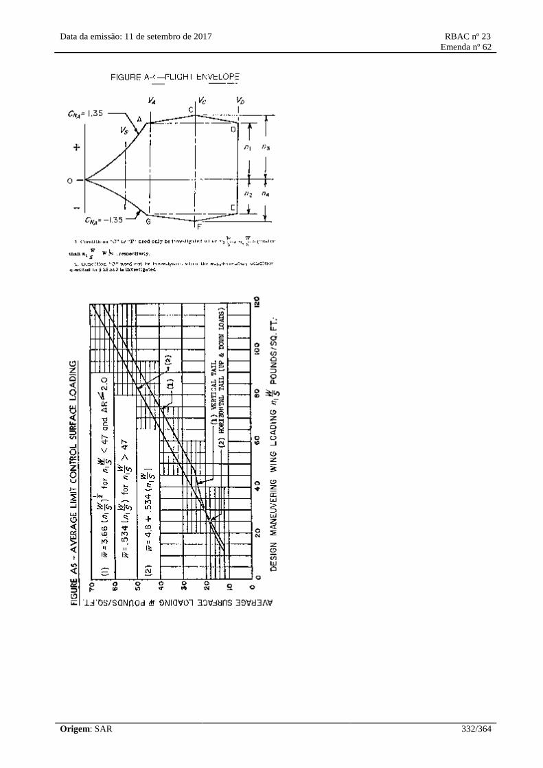
Data da emissão: 11 de setembro de 2017 RBAC nº 23
Emenda nº 62
Origem: SAR 332/364

Data da emissão: 11 de setembro de 2017 RBAC nº 23
Emenda nº 62
Origem: SAR 333/364
Figure A7—Chordwise Load Distribution for Stabilizer and Elevator or Fin and
Rudder
where:
w=average surface loading (as specified in figure A.5)
E=ratio of elevator (or rudder) chord to total stabilizer and elevator (or fin and rudder) chord.

Data da emissão: 11 de setembro de 2017 RBAC nº 23
Emenda nº 62
Origem: SAR 334/364
d′=ratio of distance of center of pressure of a unit spanwise length of combined stabilizer and
elevator (or fin and rudder) measured from stabilizer (or fin) leading edge to the local chord. Sign
convention is positive when center of pressure is behind leading edge.
c=local chord.
Note: Positive values of w, P1and P2are all measured in the same direction.
[Doc. No. 4080, 29 FR 17955, Dec. 18, 1964, as amended by Amdt. 23–7, 34 FR 13097, Aug. 13,
1969; 34 FR 14727, Sept. 24, 1969; Amdt. 23–16, 40 FR 2577, Jan. 14, 1975; Amdt. 23–28, 47 FR
13315, Mar. 29, 1982; Amdt. 23–48, 61 FR 5149, Feb. 9, 1996]
Appendix B to Part 23 [Reserved]
Appendix C to Part 23—Basic Landing Conditions
[C23.1 Basic landing conditions ]
Condition
Tail wheel type Nose wheel type
Level
landing
Tail-down
landing
Level landing
with inclined
reactions
Level landing with
nose wheel just
clear of ground
Tail-down
landing
Reference section 23.479(a)(1) 23.481(a)(1) 23.479(a)(2)(i) 23.479(a)(2)(ii) 23.481(a)(2)
and (b).
Vertical
component at c. g
nW nW nW nW nW .
Fore and aft
component at c. g
KnW 0 KnW KnW 0.
Lateral
component in
either direction at
c. g
0 0 0 0 0.
Shock absorber
extension
(hydraulic shock
absorber)
Note (2) Note (2) Note (2) Note (2) Note (2).
Shock absorber
deflection (rubber
or spring shock
absorber), percent
100 100 100 100 100.
Tire deflection Static Static Static Static Static.
Main wheel loads
(both wheels)
( n-L ) W ( n-L ) W b/d ( n-L ) W a′/d′ ( n-L ) W ( n-L ) W.

Data da emissão: 11 de setembro de 2017 RBAC nº 23
Emenda nº 62
Origem: SAR 335/364
(Vr)
Main wheel loads
(both wheels)
(Dr)
KnW 0 KnW a′/d′ KnW 0.
Tail (nose) wheel
loads (Vf)
0 ( n-L ) W a/d ( n-L ) W b′/d′ 0 0.
Tail (nose) wheel
loads (Df)
0 0 KnW b′/d′ 0 0.
Notes (1), (3), and
(4)
(4) (1) (1), (3), and (4) (3) and (4).
Note (1). K may be determined as follows: K =0.25 for W =3,000 pounds or less; K =0.33 for W
=6,000 pounds or greater, with linear variation of K between these weights.
Note (2). For the purpose of design, the maximum load factor is assumed to occur throughout the
shock absorber stroke from 25 percent deflection to 100 percent deflection unless otherwise shown
and the load factor must be used with whatever shock absorber extension is most critical for each
element of the landing gear.
Note (3). Unbalanced moments must be balanced by a rational or conservative method.
Note (4). L is defined in §23.735(b).
Note (5). n is the limit inertia load factor, at the c.g. of the airplane, selected under §23.473 (d), (f),
and (g).
[Doc. No. 4080, 29 FR 17955, Dec. 18, 1964, as amended by Amdt. 23–7, 34 FR 13099, Aug. 13,
1969]
Appendix D to Part 23—Wheel Spin-Up and Spring-Back Loads
D23.1 Wheel spin-up loads.
(a) The following method for determining wheel spin-up loads for landing conditions is based on

Data da emissão: 11 de setembro de 2017 RBAC nº 23
Emenda nº 62
Origem: SAR 336/364
NACA T.N. 863. However, the drag component used for design may not be less than the drag load
prescribed in §23.479(b).
F Hmax=1/ r e√ 2I w( V H— V c) nF Vmax/ t S
where—
F Hmax=maximum rearward horizontal force acting on the wheel (in pounds);
r e=effective rolling radius of wheel under impact based on recommended operating tire pressure
(which may be assumed to be equal to the rolling radius under a static load of n j W e) in feet;
I w=rotational mass moment of inertia of rolling assembly (in slug feet);
V H=linear velocity of airplane parallel to ground at instant of contact (assumed to be 1.2 V S0, in
feet per second);
V c=peripheral speed of tire, if prerotation is used (in feet per second) (there must be a positive
means of pre-rotation before pre-rotation may be considered);
n =equals effective coefficient of friction (0.80 may be used);
F Vmax=maximum vertical force on wheel (pounds)= n j W e,where W eand n jare defined in
§23.725;
t s=time interval between ground contact and attainment of maximum vertical force on wheel
(seconds). (However, if the value of F Vmax,from the above equation exceeds 0.8 F Vmax,the latter
value must be used for F Hmax.)
(b) The equation assumes a linear variation of load factor with time until the peak load is reached
and under this assumption, the equation determines the drag force at the time that the wheel
peripheral velocity at radius r eequals the airplane velocity. Most shock absorbers do not exactly
follow a linear variation of load factor with time. Therefore, rational or conservative allowances
must be made to compensate for these variations. On most landing gears, the time for wheel spin-up
will be less than the time required to develop maximum vertical load factor for the specified rate of
descent and forward velocity. For exceptionally large wheels, a wheel peripheral velocity equal to
the ground speed may not have been attained at the time of maximum vertical gear load. However,
as stated above, the drag spin-up load need not exceed 0.8 of the maximum vertical loads.
(c) Dynamic spring-back of the landing gear and adjacent structure at the instant just after the
wheels come up to speed may result in dynamic forward acting loads of considerable magnitude.
This effect must be determined, in the level landing condition, by assuming that the wheel spin-up
loads calculated by the methods of this appendix are reversed. Dynamic spring-back is likely to
become critical for landing gear units having wheels of large mass or high landing speeds.
[Doc. No. 4080, 29 FR 17955, Dec. 18, 1964, as amended by Amdt. 23–45, 58 FR 42167, Aug. 6,
1993]
Appendix E to Part 23 [Reserved]
Data da emissão: 11 de setembro de 2017 RBAC nº 23
Emenda nº 62
Origem: SAR 337/364
Appendix F to RBAC 23 — Test Procedure
Part I — Acceptable Test Procedure for Self-
Extinguishing Materials for Showing
Compliance With sections 23.853, 23.855, and
23.1359.
(a) Conditioning. Specimens must be
conditioned to 70 degrees F, plus or minus 5
degrees (21°C ± 3 °C), and at 50 percent plus
or minus 5 percent relative humidity until
moisture equilibrium is reached or for 24
hours. Only one specimen at a time may be
removed from the conditioning environment
immediately before subjecting it to the flame.
(b) Specimen configuration. Except as
provided for materials used in electrical wire
and cable insulation and in small parts,
materials must be tested either as a section cut
from a fabricated part as installed in the
airplane or as a specimen simulating a cut
section, such as: a specimen cut from a flat
sheet of the material or a model of the
fabricated part. The specimen may be cut from
any location in a fabricated part; however,
fabricated units, such as sandwich panels, may
not be separated for a test. The specimen
thickness must be no thicker than the minimum
thickness to be qualified for use in the airplane,
except that:
(1) Thick foam parts, such as seat cushions,
must be tested in 1/2 inch (12 mm) thickness;
(2) when showing compliance with paragraph
23.853(d)(3)(v) for materials used in small
parts that must be tested, the materials must be
tested in no more than 1/8 inch (3 mm)
thickness;
(3) when showing compliance with paragraph
23.1359(c) for materials used in electrical wire
and cable insulation, the wire and cable
specimens must be the same size as used in the
airplane. In the case of fabrics, both the warp
and fill direction of the weave must be tested to
determine the most critical flammability
conditions. When performing the tests
Apêndice F do RBAC 23 — Procedimento
de Ensaio
Parte I — Procedimento de ensaio aceitável
para materiais auto extinguíveis para
demonstrar cumprimento com as seções
23.853, 23.855 e 23.1359.
(a) Condicionamento. Os corpos de prova
devem ser condicionados a 70° F ± 5° (21°C ±
3 °C), e em 50% ± 5% de umidade relativa até
que o equilíbrio de umidade seja alcançado ou
durante 24 horas. Somente uma amostra de
cada vez pode ser retirada do ambiente de
condicionamento imediatamente antes de ser
submetida à chama.
(b) Configuração do corpo de prova. Exceto
conforme previsto para materiais usados em fio
elétrico e isolamento de cabo e em pequenas
partes, os materiais devem ser ensaiados como
uma seção cortada de uma parte fabricada
como instalado no avião ou como um corpo de
prova que simula uma seção cortada, tal como:
um corpo de prova cortado de uma folha plana
do material ou um modelo da parte fabricada.
O corpo de prova pode ser cortado de qualquer
posição da parte fabricada; contudo, as
unidades fabricadas como painéis sanduíche,
não podem ser separadas para um ensaio. A
espessura do corpo de prova não pode ser mais
grossa do que a espessura mínima a ser
qualificada para o uso no avião, exceto que:
(1) As partes de espuma grossa, como
almofadas de assento, devem ser ensaiadas com
espessura de ½ polegada (12 mm);
(2) quando demonstrando cumprimento com o
requisito 23.853(d)(3)(v) para materiais usados
em partes pequenas que devem ser ensaiadas,
os materiais devem ser ensaiados com
espessuras de não mais do que 1/8 de polegada
(3 mm);
(3) quando demonstrando cumprimento com o
parágrafo 23.1359 (c) para materiais usados em
fio elétrico e isolamento de cabo, os corpos de
prova do fio e cabo devem ser do mesmo

Data da emissão: 11 de setembro de 2017 RBAC nº 23
Emenda nº 62
Origem: SAR 338/364
prescribed in paragraphs (d) and (e) of this
appendix, the specimen must be mounted in a
metal frame so that:
(1) in the vertical tests of paragraph (d) of this
appendix, the two long edges and the upper
edge are held securely;
(2) in the horizontal test of paragraph (e) of this
appendix, the two long edges and the edge
away from the flame are held securely;
(3) the exposed area of the specimen is at least
2 inches (51 mm) wide and 12 inches (305
mm) long, unless the actual size used in the
airplane is smaller; and
(4) the edge to which the burner flame is
applied must not consist of the finished or
protected edge of the specimen but must be
representative of the actual cross section of the
material or part installed in the airplane. When
performing the test prescribed in paragraph (f)
of this appendix, the specimen must be
mounted in metal frame so that all four edges
are held securely and the exposed area of the
specimen is at least 8 inches (203 mm) by 8
inches (203 mm).
(c) Apparatus. Except as provided in paragraph
(g) of this appendix, tests must be conducted in
a draft-free cabinet in accordance with Federal
Test Method Standard 191 Method 5903
(revised Method 5902) which is available from
the General Services Administration, Business
Service Center, Region 3, Seventh and D
Streets SW., Washington, D.C. 20407, USA, or
with some other approved equivalent method.
Specimens which are too large for the cabinet
must be tested in similar draft-free conditions.
(d) Vertical test. A minimum of three
specimens must be tested and the results
averaged. For fabrics, the direction of weave
corresponding to the most critical flammability
conditions must be parallel to the longest
dimension. Each specimen must be supported
vertically. The specimen must be exposed to a
Bunsen or Tirrill burner with a nominal 3/8-
tamanho dos que são usados no avião. Em caso
de tecidos, ambas as direções de urdidura e de
preenchimento da trama devem ser ensaiadas
para determinar as condições de
inflamabilidade mais críticas. Executando os
ensaios descritos nos parágrafos (d) e (e) deste
apêndice, o corpo de prova deve ser montado
em uma armação metálica de forma que:
(1) nos ensaios verticais do parágrafo (d) deste
apêndice, as duas bordas laterais e a borda
superior estejam seguramente presas;
(2) no ensaio horizontal do parágrafo (e) deste
apêndice, as duas bordas laterais e a borda
distante da chama estejam seguramente presas;
(3) a área exposta do corpo de prova seja de
pelo menos 2 polegadas (51 mm) de largura e
12 polegadas (305 mm) de comprimento, a
menos que o tamanho real usado no avião seja
menor; e
(4) a borda na qual a chama do queimador é
aplicada não pode compor-se da borda
terminada ou protegida do corpo de prova, mas
deve ser representativa da seção real do
material ou peça instalada no avião. Quando
executando o ensaio prescrito no parágrafo (f)
deste apêndice, o corpo de prova deve ser
montado na armação metálica de tal forma que
as quatro bordas sejam seguramente presas e a
área exposta do corpo de prova seja de pelo
menos 8 polegadas (203 mm) por 8 polegadas
(203 mm).
(c) Aparelho. Exceto conforme estabelecido no
parágrafo (g) deste apêndice, os ensaios devem
ser conduzidos em um gabinete livre de
correntes de ar conforme o Federal Test
Method Standard 191 Method 5903 (Método
revisado 5902) que está disponível na General
Services Administration, Business Service
Center, Region 3, Seventh and D Streets SW.,
Washington, D.C. 20407, EUA, ou com algum
outro método equivalente aprovado. Os corpos
de prova que são muito grandes para o gabinete
devem ser ensaiados em condições

Data da emissão: 11 de setembro de 2017 RBAC nº 23
Emenda nº 62
Origem: SAR 339/364
inch (9 mm) I.D. tube adjusted to give a flame
of 1 1/2 inches (38 mm) in height. The
minimum flame temperature measured by a
calibrated thermocouple pryometer in the
center of the flame must be 1.550 °F (843 °C).
The lower edge of the specimen must be three-
fourths inch above the top edge of the burner.
The flame must be applied to the center line of
the lower edge of the specimen. For materials
covered by paragraphs 23.853(d)(3)(i) and
23.853(f), the flame must be applied for 60
seconds and then removed. For materials
covered by paragraph 23.853(d)(3)(ii), the
flame must be applied for 12 seconds and then
removed. Flame time, burn length, and flaming
time of drippings, if any, must be recorded. The
burn length determined in accordance with
paragraph (h) of this appendix must be
measured to the nearest one-tenth inch (2 mm).
(e) Horizontal test. A minimum of three
specimens must be tested and the results
averaged. Each specimen must be supported
horizontally. The exposed surface when
installed in the airplane must be face down for
the test. The specimen must be exposed to a
Bunsen burner or Tirrill burner with a nominal
3/8-inch (9 mm) I.D. tube adjusted to give a
flame of 1 ½ inches (38 mm) in height. The
minimum flame temperature measured by a
calibrated thermocouple pyrometer in the
center of the flame must be 1.550 °F (843 °C).
The specimen must be positioned so that the
edge being tested is three-fourths of an inch (19
mm) above the top of, and on the center line of,
the burner. The flame must be applied for 15
seconds and then removed. A minimum of 10
inches (254 mm) of the specimen must be used
for timing purposes, approximately 1 1/2
inches (38 mm) must burn before the burning
front reaches the timing zone, and the average
burn rate must be recorded.
(f) Forty-five degree test. A minimum of three
specimens must be tested and the results
averaged. The specimens must be supported at
an angle of 45 degrees to a horizontal surface.
The exposed surface when installed in the
aircraft must be face down for the test. The
semelhantes.
(d) Ensaio Vertical. Um mínimo de três corpos
de prova deve ser ensaiado e utilizado o
resultado médio. Para tecidos, a direção da
fibra correspondente às condições de
flamabilidade mais críticas deve estar paralela à
dimensão mais longa. Cada corpo de prova
deve ser apoiado verticalmente. O corpo de
prova deve ser exposto a um bico de Bunsen ou
queimador Tirrill com um tubo de diâmetro
interno nominal de 3/8 de polegada (9 mm)
ajustado para dar uma chama de 1 ½ polegadas
(38 mm) de altura. A temperatura de chama
mínima medida por um pirômetro termopar
calibrado, no centro da chama deve ser de
1.550° F (843 °C). A borda inferior do corpo de
prova deve estar a 3/4 de polegada (19 mm)
acima da borda superior do queimador. A
chama deve ser aplicada na linha de centro da
borda inferior do corpo de prova. Para
materiais cobertos pelos requisitos
23.853(d)(3)(i) e 23.853(f), a chama deve ser
aplicada durante 60 segundos e então retirada.
Para materiais cobertos pelos requisitos
23.853(d)(3)(ii), a chama deve ser aplicada
durante 12 segundos e então retirada. Tempo
de permanência da chama, comprimento de
queima, e o tempo de permanência da chama
nos respingos, se houver, devem ser
registrados. O comprimento de queima
determinado conforme o parágrafo (h) deste
apêndice deve ser medido o mais próximo de
1/10 de polegada (2 mm).
(e) Ensaio horizontal. Um mínimo de três
corpos de prova deve ser ensaiado e utilizado o
resultado médio. Cada corpo de prova deve ser
apoiado horizontalmente. A superfície exposta
quando instalada no avião deve estar com a
face para baixo para o ensaio. O corpo de prova
deve ser exposto a um bico de Bunsen ou
queimador Tirrill com um tubo de diâmetro
interno nominal de 3/8 de polegada (9 mm)
ajustado para dar uma chama de 1 ½ polegadas
(38 mm) de altura. A temperatura de chama
mínima, medida por um pirômetro termopar
calibrado no centro da chama deve ser de 1.550
°F (843 °C). O corpo de prova deve ser
Data da emissão: 11 de setembro de 2017 RBAC nº 23
Emenda nº 62
Origem: SAR 340/364
specimens must be exposed to a Bunsen or
Tirrill burner with a nominal 3/8 inch (9 mm)
I.D. tube adjusted to give a flame of 1 ½ inches
(38 mm) in height. The minimum flame
temperature measured by a calibrated
thermocouple pyrometer in the center of the
flame must be 1550 °F (843 °C). Suitable
precautions must be taken to avoid drafts. The
flame must be applied for 30 seconds with one-
third contacting the material at the center of the
specimen and then removed. Flame time, glow
time, and whether the flame penetrates (passes
through) the specimen must be recorded.
(g) Sixty-degree test. A minimum of three
specimens of each wire specification (make
and size) must be tested. The specimen of wire
or cable (including insulation) must be placed
at an angle of 60 degrees with the horizontal in
the cabinet specified in paragraph (c) of this
appendix, with the cabinet door open during
the test or placed within a chamber
approximately 2 feet high × 1 foot × 1 foot,
(610 x 305 x 305 mm) open at the top and at
one vertical side (front), that allows sufficient
flow of air for complete combustion but is free
from drafts. The specimen must be parallel to
and approximately 6 inches (152 mm) from the
front of the chamber. The lower end of the
specimen must be held rigidly clamped. The
upper end of the specimen must pass over a
pulley or rod and must have an appropriate
weight attached to it so that the specimen is
held tautly throughout the flammability test.
The test specimen span between lower clamp
and upper pulley or rod must be 24 inches (610
mm) and must be marked 8 inches (203 mm)
from the lower end to indicate the central point
for flame application. A flame from a Bunsen
or Tirrill burner must be applied for 30 seconds
at the test mark. The burner must be mounted
underneath the test mark on the specimen,
perpendicular to the specimen and at an angle
of 30 degrees to the vertical plane of the
specimen. The burner must have a nominal
bore of three-eighths inch (9 mm), and must be
adjusted to provide a three-inch-high (76 mm)
flame with an inner cone approximately one-
third of the flame height. The minimum
posicionado de tal forma que a borda a ser
ensaiada fique a 3/4 de polegada (19 mm)
acima do topo, e na linha de centro do
queimador. A chama deve ser aplicada durante
15 segundos e então retirada. Um mínimo de
10 polegadas (254 mm) do corpo de prova deve
ser usado com a finalidade de cronometragem,
aproximadamente 1 ½ polegadas (38 mm)
devem queimar-se antes que a frente de chama
alcance a zona de cronometragem, e a taxa
média de queima deve ser registrada.
(f) Ensaio a quarenta e cinco graus. Um
mínimo de três corpos de prova deve ser
ensaiado e utilizado o resultado médio. Os
corpos de prova devem ser apoiados em um
ângulo de 45 graus em relação a uma superfície
horizontal. A superfície exposta quando
instalada no avião deve estar com a face para
baixo para o ensaio. O corpo de prova deve ser
exposto a um bico de Bunsen ou queimador
Tirrill com um tubo de diâmetro interno
nominal de 3/8 de polegada (9 mm) ajustado
para dar uma chama de 1 ½ polegadas (38 mm)
de altura. A temperatura de chama mínima,
medida por um pirômetro termopar calibrado
no centro da chama deve ser de 1.550 ° F (843
°C). As precauções apropriadas devem ser
tomadas para evitar uma corrente de ar. A
chama deve ser aplicada durante 30 segundos
com um terço da mesma em contato com o
material no centro do corpo de prova, e então
removida. O tempo de permanência da chama,
o tempo de brasa, e se a chama penetra (passa)
pelo corpo de prova deve ser registrado.
(g) Ensaio a sessenta graus. Um mínimo de três
corpos de prova de cada especificação de fio
(modelo e tamanho) deve ser ensaiado. O corpo
de prova do fio ou cabo (inclusive o
isolamento) deve ser colocado em um ângulo
de 60 graus com a horizontal no gabinete
especificado no parágrafo (c) deste apêndice,
com a porta do gabinete aberta durante o ensaio
ou colocado dentro de uma câmara de
aproximadamente 2 pés de altura x 1 pé x 1 pé
(610 x 305 x 305 mm), aberta em cima e em
um lado vertical (frente), que permita o fluxo
suficiente do ar para a combustão completa

Data da emissão: 11 de setembro de 2017 RBAC nº 23
Emenda nº 62
Origem: SAR 341/364
temperature of the hottest portion of the flame,
as measured with a calibrated thermocouple
pyrometer, may not be less than 1.750 °F (954
°C). The burner must be positioned so that the
hottest portion of the flame is applied to the test
mark on the wire. Flame time, burn length, and
flaming time drippings, if any, must be
recorded. The burn length determined in
accordance with paragraph (h) of this appendix
must be measured to the nearest one-tenth inch
(2 mm). Breaking of the wire specimen is not
considered a failure.
(h) Burn length. Burn length is the distance
from the original edge to the farthest evidence
of damage to the test specimen due to flame
impingement, including areas of partial or
complete consumption, charring, or
embrittlement, but not including areas sooted,
stained, warped, or discolored, nor areas where
material has shrunk or melted away from the
heat source.
Part II -- Test Method To Determine the
Flammability and Flame Propagation
Characteristics of Thermal/Acoustic Insulation
Materials
Use this test method to evaluate the
flammability and flame propagation
characteristics of thermal/acoustic insulation
when exposed to both a radiant heat source and
a flame.
(a) Definitions.
Flame propagation means the furthest distance
of the propagation of visible flame towards the
far end of the test specimen, measured from the
midpoint of the ignition source flame. Measure
this distance after initially applying the ignition
source and before all flame on the test
specimen is extinguished. The measurement is
not a determination of burn length made after
the test.
Radiant heat source means an electric or air
propane panel.
mas livre da corrente de ar. O corpo de prova
deve estar paralelo a e aproximadamente 6
polegadas (152 mm) da frente da câmara. A
extremidade inferior do corpo de prova deve
ser mantida rigidamente presa. A extremidade
superior do corpo de prova deve passar por
cima de uma polia ou roldana e deve ter um
peso apropriado amarrado a ele para que o
corpo de prova seja mantido esticado em todas
as partes do ensaio de flamabilidade. O
comprimento do corpo de prova entre a
extremidade inferior presa e a extremidade
superior na polia ou roldana deve ser de 24
polegadas (610 mm) e deve ser marcado a 8
polegadas (203 mm) a partir da extremidade
inferior do corpo de prova para indicar o ponto
central para a aplicação da chama. Uma chama
de um bico de Bunsen ou queimador Tirrill
deve ser aplicada durante 30 segundos na
marca de ensaio. O queimador deve ser
montado embaixo da marca de ensaio do corpo
de prova, perpendicular ao corpo de prova e em
um ângulo de 30 graus ao plano vertical do
corpo de prova. O queimador deve ter um furo
nominal de 3/8 de polegada (9 mm), e deve ser
ajustado para fornecer uma chama de três
polegadas (76 mm) de altura com um cone
interno de aproximadamente um terço da altura
de chama.
A temperatura mínima da porção mais quente
da chama, medida por um pirômetro termopar
calibrado, não pode ser menos do que 1.750°F
(954 °C). O queimador deve ser posicionado de
modo que a porção mais quente da chama seja
aplicada na marca de ensaio no fio. O tempo de
permanecia da chama, comprimento de queima,
e o tempo de permanência da chama dos
respingos, se houver, devem ser registrados. O
comprimento de queima determinado conforme
o parágrafo (h) deste apêndice deve ser medido
o mais próximo de 1/10 de polegada (2 mm). A
ruptura do corpo de prova do fio não é
considerada uma falha.
(h) Comprimento de queima. Comprimento de
queima é a distância da borda original até a
evidência mais distante de dano ao corpo de
prova ensaiado devido a influência da chama,

Data da emissão: 11 de setembro de 2017 RBAC nº 23
Emenda nº 62
Origem: SAR 342/364
Thermal/acoustic insulation means a material
or system of materials used to provide thermal
and/or acoustic protection. Examples include
fiberglass or other batting material
encapsulated by a film covering and foams.
Zero point means the point of application of the
pilot burner to the test specimen.
(b) Test apparatus.
(1) Radiant panel test chamber. Conduct tests
in a radiant panel test chamber (see figure F1
above). Place the test chamber under an
exhaust hood to facilitate clearing the chamber
of smoke after each test. The radiant panel test
chamber must be an enclosure 55 inches (1.397
mm) long by 19.5 inches (495 mm) deep by 28
inches (710 mm) to 30 inches (maximum) (762
mm) above the test specimen. Insulate the
sides, ends, and top with a fibrous ceramic
insulation, such as Kaowool MTM board. On
the front side, provide a 52 by 12-inch (1.321
by 305 mm) draft-free, high-temperature, glass
window for viewing the sample during testing.
Place a door below the window to provide
access to the movable specimen platform
holder. The bottom of the test chamber must be
a sliding steel platform that has provision for
securing the test specimen holder in a fixed and
level position. The chamber must have an
internal chimney with exterior dimensions of
5.1 inches (129 mm) wide, by 16.2 inches (411
mm) deep by 13 inches (330 mm) high at the
opposite end of the chamber from the radiant
inclusive áreas de consumo parcial ou
completo, carbonização, ou fragilização, mas
não inclui áreas cobertas com fuligem, sujas,
empenadas, ou descolorada, nem áreas onde o
material se encolheu ou fundiu pela fonte de
calor.
Parte II -- Método de ensaio para determinar a
características de inflamabilidade e propagação
de chama para materiais de isolamento
térmico/acústico.
Utilize este método de ensaio para avaliar as
características de inflamabilidade e propagação
de chama do Isolamento Térmico/Acústico,
quando expostos tanto a uma fonte de calor
radiante quanto a uma chama.
(a) Definições.
"Propagação de Chama" significa a maior
distância de propagação de chama visível em
direção a extremidade do corpo de prova,
medido a partir do ponto médio da fonte de
ignição da chama. Medir esta distância depois
de aplicar inicialmente a fonte de ignição e
antes que toda a chama no corpo de prova seja
extinta. A medição não é uma determinação do
comprimento de queima feito depois do ensaio.
"Fonte de calor radiante" significa um painel
elétrico ou painel de ar propano.
"O isolamento térmico/acústico" significa um
material ou o sistema de materiais usados para
fornecer proteção térmica e/ou acústica. Os
exemplos incluem a fibra de vidro ou outro
material de feltro encapsulado por uma película
de cobertura e espumas.
"Ponto zero" significa o ponto de aplicação do
queimador piloto no corpo de prova.
(b) Aparelho de ensaio.

Data da emissão: 11 de setembro de 2017 RBAC nº 23
Emenda nº 62
Origem: SAR 343/364
energy source. The interior dimensions must be
4.5 inches (114 mm) wide by 15.6 inches (395
mm) deep. The chimney must extend to the top
of the chamber (see figure F2).
(2) Radiant heat source. Mount the radiant heat
energy source in a cast iron frame or
equivalent. An electric panel must have six, 3-
inch wide emitter strips. The emitter strips
must be perpendicular to the length of the
panel. The panel must have a radiation surface
of 12 7/8 by 18 1/2 inches (327 by 470 mm).
The panel must be capable of operating at
temperatures up to 1.300 °F (704 °C). An air
propane panel must be made of a porous
refractory material and have a radiation surface
of 12 by 18 inches (305 by 457 mm). The panel
must be capable of operating at temperatures
up to 1.500 °F (816 °C). See figures F3a and
F3b.
(1) Câmara de ensaio de painel radiante.
Conduzir ensaios em uma câmara de ensaio de
painel radiante (ver a figura F1 acima). Colocar
a câmara de ensaio embaixo de uma cabine de
exaustão para facilitar a limpeza da fumaça da
câmara depois de cada ensaio. A câmara de
ensaio de painel radiante deve ser um recinto
cercado de 55 polegadas (1.397 mm) de
comprimento por 19.5 polegadas (495 mm) de
profundidade por 28 polegadas (710 mm) a 30
polegadas (máximo) 762 mm acima do corpo
de prova. Isolar os lados, fundo, e topo com um
isolamento cerâmico fibroso, como uma placa
de Kaowool MTM. No lado da frente, fornece
uma janela de vidro com 52 por 12 polegadas
(1.321 por 305 mm) sem correntes de ar, para
altas temperaturas, para visualização da
amostra durante o ensaio. Colocar uma porta
abaixo da janela para fornecer o acesso à
plataforma móvel de suporte do corpo de
prova. O fundo da câmara de ensaio deve ser
uma plataforma deslizante de aço projetada
para garantir que suporte do corpo de prova
fique em uma posição fixa e nivelada.
A câmara deve ter uma chaminé interna com
dimensões exteriores de 5.1 polegadas (129
mm) de largura, por 16.2 polegadas (411 mm)
de profundidade por 13 polegadas (330 mm) de
altura no fundo da câmara, oposto a fonte de
energia radiante. As dimensões interiores
devem ser de 4.5 polegadas (114 mm) de
largura por 15.6 polegadas (395 mm) de
profundidade. A chaminé deve estender-se ao

Data da emissão: 11 de setembro de 2017 RBAC nº 23
Emenda nº 62
Origem: SAR 344/364
(i) Electric radiant panel. The radiant panel
must be 3-phase and operate at 208 volts. A
single-phase, 240 volt panel is also acceptable.
Use a solid-state power controller and
microprocessor- based controller to set the
electric panel operating parameters.
(ii) Gas radiant panel. Use propane (liquid
petroleum gas--2.1 UN 1075) for the radiant
panel fuel. The panel fuel system must consist
of a venturi-type aspirator for mixing gas and
air at approximately atmospheric pressure.
Provide suitable instrumentation for monitoring
and controlling the flow of fuel and air to the
panel. Include an air flow gauge, an air flow
regulator, and a gas pressure gauge.
(iii) Radiant panel placement. Mount the panel
in the chamber at 30 degrees to the horizontal
specimen plane, and 7 1/2 inches above the
zero point of the specimen.
(3) Specimen holding system.
topo da câmara (ver figura F2).
(2) Fonte de calor radiante. Monte a fonte de
energia de calor radiante em uma armação de
ferro fundido ou equivalente. Um painel
elétrico deve ter seis, tiras emissoras de 3-
polegadas de largura. As tiras emissoras devem
estar perpendiculares ao comprimento do
painel. O painel deve ter uma superfície de
radiação de 12 7/8 por 18,5 polegadas (327 em
470 mm). O painel deve ser capaz de funcionar
em temperaturas de até 1.300 °F (704 °C). Um
painel de propano deve ser feito de um material
refratário poroso e ter uma superfície de
radiação de 12 por 18 polegadas (305 por 457
mm). O painel deve ser capaz de funcionar em
temperaturas de até 1.500 °F (816 °C). Ver as
figuras F3a e F3b.

Data da emissão: 11 de setembro de 2017 RBAC nº 23
Emenda nº 62
Origem: SAR 345/364
(i) The sliding platform serves as the housing
for test specimen placement. Brackets may be
attached (via wing nuts) to the top lip of the
platform in order to accommodate various
thicknesses of test specimens. Place the test
specimens on a sheet of Kaowool MTM board
or 1260 Standard Board (manufactured by
Thermal Ceramics and available in Europe), or
equivalent, either resting on the bottom lip of
the sliding platform or on the base of the
brackets. It may be necessary to use multiple
sheets of material based on the thickness of the
test specimen (to meet the sample height
requirement). Typically, these non-combustible
sheets of material are available in 1/4-inch (6
mm) thicknesses. See figure F4. A sliding
platform that is deeper than the 2-inch
(50.8mm) platform shown in figure F4 is also
acceptable as long as the sample height
requirement is met.
(ii) Attach a 1/2-inch (13 mm) piece of
Kaowool MTM board or other high
temperature material measuring 41 1/2 by 8 1/4
inches (1054 by 210 mm) to the back of the
platform. This board serves as a heat retainer
and protects the test specimen from excessive
preheating. The height of this board may not
impede the sliding platform movement (in and
out of the test chamber). If the platform has
been fabricated such that the back side of the
platform is high enough to prevent excess
preheating of the specimen when the sliding
platform is out, a retainer board is not
necessary.
(i) Painel Radiante Elétrico. O painel radiante
deve ser de 3-fases e operar em 208 volts. Um
painel de única fase, 240 volts também é
aceitável. Utilizar um controlador de força de
estado sólido e microprocessador controlador
para definir os parâmetros operacionais do
painel elétrico.
(ii) Painel radiante a gás. Usar o propano (gás
de petróleo líquido - a 2.1 UN 1075) como
combustível do painel radiante. O sistema de
combustível do painel deve compor-se de um
aspirador do tipo Venturi para misturar o gás e
o ar na pressão aproximadamente atmosférica.
Fornecer a instrumentação adequada para
monitorar e controlar o fluxo de combustível e
de ar ao painel. Incluir um medidor de fluxo de
ar, um regulador de fluxo de ar, e um medidor
de pressão de gás.
(iii) Colocação do painel radiante. Montar o
painel na câmara a 30 graus em relação ao
plano horizontal do corpo de prova, e 7,5
polegadas (127 mm) acima do ponto zero do

Data da emissão: 11 de setembro de 2017 RBAC nº 23
Emenda nº 62
Origem: SAR 346/364
(iii) Place the test specimen horizontally on the
non-combustible board(s). Place a steel
retaining/securing frame fabricated of mild
steel, having a thickness of 1/8-inch (3.2 mm)
and overall dimensions of 23 by 13 1/8 inches
(584 by 333 mm) with a specimen opening of
19 by 10 3/4 inches (483 by 273 mm) over the
test specimen. The front, back, and right
portions of the top flange of the frame must rest
on the top of the sliding platform, and the
bottom flanges must pinch all 4 sides of the test
specimen. The right bottom flange must be
flush with the sliding platform. See figure F5.
(4) Pilot Burner. The pilot burner used to ignite
the specimen must be a BernzomaticTM
commercial propane venturi torch with an
axially symmetric burner tip and a propane
supply tube with an orifice diameter of 0.006
inches (0.15 mm). The length of the burner
tube must be 2 7/8 inches (71 mm). The
propane flow must be adjusted via gas pressure
through an in-line regulator to produce a blue
inner cone length of 3/4-inch (19 mm). A 3/4-
inch (19 mm) guide (such as a thin strip of
metal) may be soldered to the top of the burner
to aid in setting the flame height. The overall
flame length must be approximately 5 inches
long (127 mm). Provide a way to move the
corpo de prova.
(3) Sistema de alojamento do corpo de prova.
(i) A plataforma deslizante serve como o
alojamento para colocação do corpo de prova.
Os suportes podem ser presos (através de
porcas-borboletas) a aba superior da plataforma
para acomodar várias espessuras de corpos de
prova. Colocar os corpos de prova em uma
folha de placa de Kaowool MTM ou placa
1260 Padrão (fabricados pela Thermal
Ceramics e disponível na Europa), ou
equivalente, que repousa na aba da superfície
inferior da plataforma deslizante ou na base dos
suportes. Pode ser necessário usar múltiplas
folhas do material em função da espessura do
corpo de prova (para encontrar a altura exigida
da amostra). Normalmente, essas folhas não-
combustíveis do material estão disponíveis na
espessura de 1/4 polegada (6 mm). Ver figura
F4. Uma plataforma deslizante que é mais
profunda do que a plataforma de 2 polegadas
(de 50.8 mm) mostrada na figura F4 é também
aceitável desde que a altura exigida da amostra
seja satisfeita.
(ii) Prender um pedaço de placa de Kaowool
MTM de 1/2 polegada (13 mm) ou outro
material para alta temperatura medindo 41,5
por 8,25 polegadas (1054 por 210 mm) para às
costas da plataforma. Esta placa funciona como
um retentor de calor e protege o corpo de prova
do pré-aquecemento excessivo. A altura desta
placa não pode impedir o movimento da
plataforma deslizante (dentro e fora da câmara

Data da emissão: 11 de setembro de 2017 RBAC nº 23
Emenda nº 62
Origem: SAR 347/364
burner out of the ignition position so that the
flame is horizontal and at least 2 inches (50
mm) above the specimen plane. See figure F6.
(5) Thermocouples. Install a 24 American Wire
Gauge (AWG) Type K (Chromel- Alumel)
thermocouple in the test chamber for
temperature monitoring. Insert it into the
chamber through a small hole drilled through
the back of the chamber. Place the
thermocouple so that it extends 11 inches (279
mm) out from the back of the chamber wall, 11
1/2 inches (292 mm) from the right side of the
chamber wall, and is 2 inches (51 mm) below
the radiant panel. The use of other
thermocouples is optional.
(6) Calorimeter. The calorimeter must be a
one-inch cylindrical water-cooled, total heat
flux density, foil type Gardon Gage that has a
range of 0 to 5 BTU/ft 2-second (0 to 5,7
Watts/cm 2).
(7) Calorimeter calibration specification and
procedure.
(i) Calorimeter specification.
(A) Foil diameter must be 0,25 +/- 0,005 inches
(6,35 +/- 0,13 mm).
(B) Foil thickness must be 0,0005 +/- 0,0001
inches (0,013 +/- 0,0025 mm).
(C) Foil material must be thermocouple grade
Constantan.
(D) Temperature measurement must be a
Copper Constantan thermocouple.
(E) The copper center wire diameter must be
de ensaio). Se a plataforma tiver sido fabricada
de tal modo que o lado traseiro da plataforma é
alto o suficiente para prevenir o pré-
aquecimento excessivo do corpo de prova
quando a plataforma deslizante está fora, uma
placa retentora não é necessária.
(iii) Colocar o corpo de prova horizontalmente
na placa não-combustível. Colocar uma
armação de aço de retenção/segurança,
fabricada do aço doce, tendo uma espessura de
1/8 polegada (3,2 mm) e dimensões totais de 23
por 13 1/8 polegadas (584 por 333 mm) com
uma abertura do corpo de prova de 19 por 10
3/4 polegadas (483 por 273 mm) acima do
corpo de prova. A frente, atrás, e as partes
direitas do flange superior da armação devem
ficar no topo da plataforma deslizante, e os
flanges de fundo devem apertar os 4 lados do
corpo de prova. O flange direito da superfície
inferior deve estar nivelado com a plataforma
deslizante. Ver figura F5.
(4) Queimador Piloto. O queimador piloto
usado para acender o corpo de prova deve ser
uma tocha de tubo de Venturi de propano
comercial BernzomaticTM com uma ponta do
queimador axial mente simétrica e um tubo de
fornecimento de propano com um diâmetro de
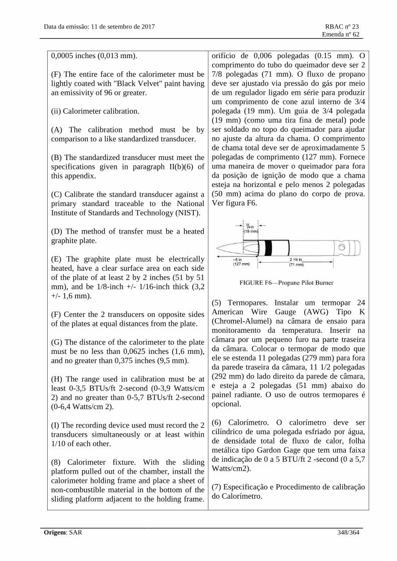
Data da emissão: 11 de setembro de 2017 RBAC nº 23
Emenda nº 62
Origem: SAR 348/364
0,0005 inches (0,013 mm).
(F) The entire face of the calorimeter must be
lightly coated with "Black Velvet" paint having
an emissivity of 96 or greater.
(ii) Calorimeter calibration.
(A) The calibration method must be by
comparison to a like standardized transducer.
(B) The standardized transducer must meet the
specifications given in paragraph II(b)(6) of
this appendix.
(C) Calibrate the standard transducer against a
primary standard traceable to the National
Institute of Standards and Technology (NIST).
(D) The method of transfer must be a heated
graphite plate.
(E) The graphite plate must be electrically
heated, have a clear surface area on each side
of the plate of at least 2 by 2 inches (51 by 51
mm), and be 1/8-inch +/- 1/16-inch thick (3,2
+/- 1,6 mm).
(F) Center the 2 transducers on opposite sides
of the plates at equal distances from the plate.
(G) The distance of the calorimeter to the plate
must be no less than 0,0625 inches (1,6 mm),
and no greater than 0,375 inches (9,5 mm).
(H) The range used in calibration must be at
least 0-3,5 BTUs/ft 2-second (0-3,9 Watts/cm
2) and no greater than 0-5,7 BTUs/ft 2-second
(0-6,4 Watts/cm 2).
(I) The recording device used must record the 2
transducers simultaneously or at least within
1/10 of each other.
(8) Calorimeter fixture. With the sliding
platform pulled out of the chamber, install the
calorimeter holding frame and place a sheet of
non-combustible material in the bottom of the
sliding platform adjacent to the holding frame.
orifício de 0,006 polegadas (0.15 mm). O
comprimento do tubo do queimador deve ser 2
7/8 polegadas (71 mm). O fluxo de propano
deve ser ajustado via pressão do gás por meio
de um regulador ligado em série para produzir
um comprimento de cone azul interno de 3/4
polegada (19 mm). Um guia de 3/4 polegada
(19 mm) (como uma tira fina de metal) pode
ser soldado no topo do queimador para ajudar
no ajuste da altura da chama. O comprimento
de chama total deve ser de aproximadamente 5
polegadas de comprimento (127 mm). Fornece
uma maneira de mover o queimador para fora
da posição de ignição de modo que a chama
esteja na horizontal e pelo menos 2 polegadas
(50 mm) acima do plano do corpo de prova.
Ver figura F6.
(5) Termopares. Instalar um termopar 24
American Wire Gauge (AWG) Tipo K
(Chromel-Alumel) na câmara de ensaio para
monitoramento da temperatura. Inserir na
câmara por um pequeno furo na parte traseira
da câmara. Colocar o termopar de modo que
ele se estenda 11 polegadas (279 mm) para fora
da parede traseira da câmara, 11 1/2 polegadas
(292 mm) do lado direito da parede de câmara,
e esteja a 2 polegadas (51 mm) abaixo do
painel radiante. O uso de outros termopares é
opcional.
(6) Calorímetro. O calorímetro deve ser
cilíndrico de uma polegada esfriado por água,
de densidade total de fluxo de calor, folha
metálica tipo Gardon Gage que tem uma faixa
de indicação de 0 a 5 BTU/ft 2 -second (0 a 5,7
Watts/cm2).
(7) Especificação e Procedimento de calibração
do Calorímetro.

Data da emissão: 11 de setembro de 2017 RBAC nº 23
Emenda nº 62
Origem: SAR 349/364
This will prevent heat losses during calibration.
The frame must be 13 1/8 inches (333 mm)
deep (front to back) by 8 inches (203 mm) wide
and must rest on the top of the sliding platform.
It must be fabricated of 1/8-inch (3.2 mm) flat
stock steel and have an opening that
accommodates a 1/2-inch (12.7 mm) thick
piece of refractory board, which is level with
the top of the sliding platform. The board must
have three 1-inch (25.4 mm) diameter holes
drilled through the board for calorimeter
insertion. The distance to the radiant panel
surface from the centerline of the first hole
("zero" position) must be 7 1/2 ± 1/8- inches
(191 ± 3 mm). The distance between the
centerline of the first hole to the centerline of
the second hole must be 2 inches (51 mm). It
must also be the same distance from the
centerline of the second hole to the centerline
of the third hole. See figure F7. A calorimeter
holding frame that differs in construction is
acceptable as long as the height from the
centerline of the first hole to the radiant panel
and the distance between holes is the same as
described in this paragraph.
(9) Instrumentation. Provide a calibrated
recording device with an appropriate range or a
computerized data acquisition system to
measure and record the outputs of the
calorimeter and the thermocouple. The data
acquisition system must be capable of
recording the calorimeter output every second
during calibration.
(10) Timing device. Provide a stopwatch or
(i) Especificação do Calorímetro.
(A) O diâmetro da folha metálica deve ser de
0,25 +/- 0,005 polegadas (6,35 ± 0,13 mm).
(B) A espessura da folha metálica deve ser
0,0005 +/- 0,0001 polegadas (0,013 ± 0,0025
mm).
(C) O material da folha metálica deve ser de
liga de Constantan da classe do termopar.
(D) A medição de temperatura deve ser um
termopar de liga de cobre Constantan.
(E) O diâmetro do arame central de cobre deve
ser de 0,0005 polegadas (0,013 mm).
(F) Toda a face do calorímetro deve ser
levemente revestida com uma tinta "Preta
Aveludada" tendo uma emissividade de 96 ou
maior.
(ii) Calibração do Calorímetro.
(A) O método de calibração deve ser feito por
comparação a um transdutor similar
padronizado.
(B) O transdutor padronizado deve satisfazer as
especificações dadas no parágrafo II(b)(6)
deste apêndice.
(C) Calibrar o transdutor padrão contra um
padrão primário rastreável ao Instituto
Nacional de Padrões e Tecnologia (NIST) ou
outro Laboratório Nacional reconhecido pelo
NIST.
(D) O método de transferência deve ser uma
placa de grafite aquecida.
(E) A placa de grafite deve ser eletricamente
aquecida, ter uma área superficial limpa em
cada lado da placa de pelo menos 2 por 2
polegadas (51 por 51 mm), e ter espessura de
1/8 +/-1/16 polegada (3.2 ± 1.6 mm).
(F) Centralizar os 2 transdutores em lados

Data da emissão: 11 de setembro de 2017 RBAC nº 23
Emenda nº 62
Origem: SAR 350/364
other device, accurate to ± 1 second/hour, to
measure the time of application of the pilot
burner flame.
(c) Test specimens.
(1) Specimen preparation. Prepare and test a
minimum of three test specimens. If an
oriented film cover material is used, prepare
and test both the warp and fill directions.
(2) Construction. Test specimens must include
all materials used in construction of the
insulation (including batting, film, scrim, tape,
etc.). Cut a piece of core material such as foam
or fiberglass, and cut a piece of film cover
material (if used) large enough to cover the
core material. Heat sealing is the preferred
method of preparing fiberglass samples, since
they can be made without compressing the
fiberglass ("box sample"). Cover materials that
are not heat sealable may be stapled, sewn, or
taped as long as the cover material is
sufficiently over-cut to be drawn down the
sides without compressing the core material.
The fastening means should be as continuous
as possible along the length of the seams. The
specimen thickness must be of the same
thickness as installed in the airplane.
(3) Specimen Dimensions. To facilitate proper
placement of specimens in the sliding platform
housing, cut non-rigid core materials, such as
fiberglass, 12 1/2 inches (318mm) wide by 23
inches (584mm) long. Cut rigid materials, such
as foam, 11 1/2 ± 1/4 inches (292 mm ± 6mm)
wide by 23 inches (584mm) long in order to fit
properly in the sliding platform housing and
provide a flat, exposed surface equal to the
opening in the housing.
(d) Specimen conditioning. Condition the test
specimens at 70 ± 5 °F (21 ± 2 °C) and 55
percent ± 10 percent relative humidity, for a
minimum of 24 hours prior to testing.
(e) Apparatus Calibration.
(1) With the sliding platform out of the
opostos da placa em iguais distâncias da placa.
(G) A distância do calorímetro à placa não
pode ser menor que 0.0625 polegadas (1.6
mm), e não maior do que 0.375 polegadas (9.5
mm).
(H) A faixa de indicação usada na calibração
deve ser pelo menos 0-3.5 BTUs/ ft 2 second
(0-3,9 Watts/cm2) e não maior do que 0-5.7
BTUs/ ft 2 second (0-6,4 Watts/cm2 ).
(I) O dispositivo de registro usado deve
registrar os 2 transdutores simultaneamente ou
pelo menos dentro de 1/10 um do outro.
(8) Instalação do Calorímetro. Com a
plataforma deslizante fora da câmara, instalar a
armação que mantém o calorímetro e colocar
uma folha do material não-combustível na
superfície inferior da plataforma deslizante
adjacente à armação. Isso irá evitar perdas de
calor durante a calibração. A armação deve ser
13 1/8 polegadas (333 mm) de profundidade
(da frente ao fundo) por 8 polegadas (203 mm)
de largura e deve repousar no topo da
plataforma deslizante. Deve ser fabricada de
chapa plana de aço com 1/8 polegada (3,2 mm)
e ter uma abertura que acomode uma parte de
uma placa de refratário com 1/2 polegada (12.7
mm) de espessura, que está nivelada com o
topo da plataforma deslizante. A placa deve ter
três furos de 1 polegada (25.4 mm) de diâmetro
para inserção do calorímetro. A distância da
superfície do painel radiante até a linha central
do primeiro furo (posição "zero") deve ser 7 ½
+/- 1/8 polegadas (191 ± 3 mm). A distância
entre a linha central do primeiro furo até a linha
central do segundo furo deve ser de 2
polegadas (51 mm). Esta também deve ser a
mesma distância da linha central do segundo
furo até a linha central do terceiro furo. Ver
figura F7. Uma armação para manter o
calorímetro que se diferencia na construção é
aceitável desde que a altura da linha central do
primeiro furo até o painel radiante e a distância
entre os furos seja a mesma, tal como descrito
neste parágrafo.
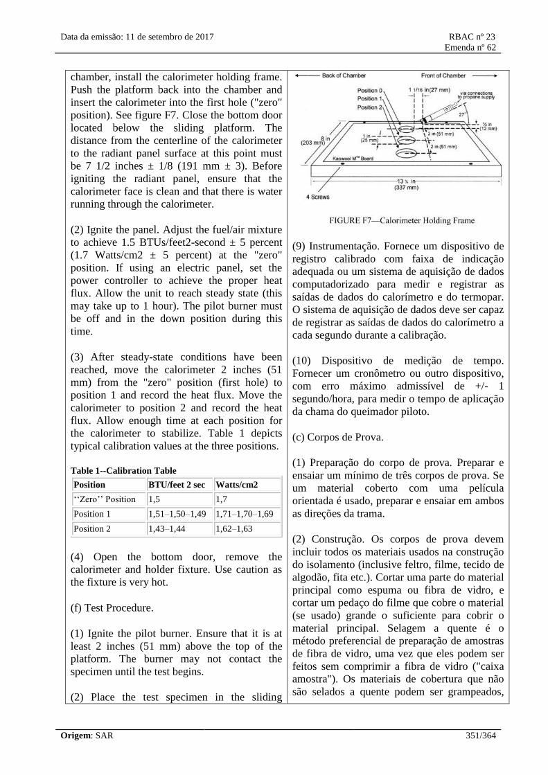
Data da emissão: 11 de setembro de 2017 RBAC nº 23
Emenda nº 62
Origem: SAR 351/364
chamber, install the calorimeter holding frame.
Push the platform back into the chamber and
insert the calorimeter into the first hole ("zero"
position). See figure F7. Close the bottom door
located below the sliding platform. The
distance from the centerline of the calorimeter
to the radiant panel surface at this point must
be 7 1/2 inches ± 1/8 (191 mm ± 3). Before
igniting the radiant panel, ensure that the
calorimeter face is clean and that there is water
running through the calorimeter.
(2) Ignite the panel. Adjust the fuel/air mixture
to achieve 1.5 BTUs/feet2-second ± 5 percent
(1.7 Watts/cm2 ± 5 percent) at the "zero"
position. If using an electric panel, set the
power controller to achieve the proper heat
flux. Allow the unit to reach steady state (this
may take up to 1 hour). The pilot burner must
be off and in the down position during this
time.
(3) After steady-state conditions have been
reached, move the calorimeter 2 inches (51
mm) from the "zero" position (first hole) to
position 1 and record the heat flux. Move the
calorimeter to position 2 and record the heat
flux. Allow enough time at each position for
the calorimeter to stabilize. Table 1 depicts
typical calibration values at the three positions.
Table 1--Calibration Table
Position BTU/feet 2 sec Watts/cm2
‘‘Zero’’ Position 1,5 1,7
Position 1 1,51–1,50–1,49 1,71–1,70–1,69
Position 2 1,43–1,44 1,62–1,63
(4) Open the bottom door, remove the
calorimeter and holder fixture. Use caution as
the fixture is very hot.
(f) Test Procedure.
(1) Ignite the pilot burner. Ensure that it is at
least 2 inches (51 mm) above the top of the
platform. The burner may not contact the
specimen until the test begins.
(2) Place the test specimen in the sliding
(9) Instrumentação. Fornece um dispositivo de
registro calibrado com faixa de indicação
adequada ou um sistema de aquisição de dados
computadorizado para medir e registrar as
saídas de dados do calorímetro e do termopar.
O sistema de aquisição de dados deve ser capaz
de registrar as saídas de dados do calorímetro a
cada segundo durante a calibração.
(10) Dispositivo de medição de tempo.
Fornecer um cronômetro ou outro dispositivo,
com erro máximo admissível de +/- 1
segundo/hora, para medir o tempo de aplicação
da chama do queimador piloto.
(c) Corpos de Prova.
(1) Preparação do corpo de prova. Preparar e
ensaiar um mínimo de três corpos de prova. Se
um material coberto com uma película
orientada é usado, preparar e ensaiar em ambos
as direções da trama.
(2) Construção. Os corpos de prova devem
incluir todos os materiais usados na construção
do isolamento (inclusive feltro, filme, tecido de
algodão, fita etc.). Cortar uma parte do material
principal como espuma ou fibra de vidro, e
cortar um pedaço do filme que cobre o material
(se usado) grande o suficiente para cobrir o
material principal. Selagem a quente é o
método preferencial de preparação de amostras
de fibra de vidro, uma vez que eles podem ser
feitos sem comprimir a fibra de vidro ("caixa
amostra"). Os materiais de cobertura que não
são selados a quente podem ser grampeados,

Data da emissão: 11 de setembro de 2017 RBAC nº 23
Emenda nº 62
Origem: SAR 352/364
platform holder. Ensure that the test sample
surface is level with the top of the platform. At
"zero" point, the specimen surface must be 7
1/2 inches ± 1/8 inch (191 mm ± 3) below the
radiant panel.
(3) Place the retaining/securing frame over the
test specimen. It may be necessary (due to
compression) to adjust the sample (up or down)
in order to maintain the distance from the
sample to the radiant panel (7 1/2 inches ± 1/8
inch (191 mm ± 3) at "zero" position). With
film/fiberglass assemblies, it is critical to make
a slit in the film cover to purge any air inside.
This allows the operator to maintain the proper
test specimen position (level with the top of the
platform) and to allow ventilation of gases
during testing. A longitudinal slit,
approximately 2 inches (51mm) in length, must
be centered 3 inches ± 1/2 inch (76mm ±
13mm) from the left flange of the securing
frame. A utility knife is acceptable for slitting
the film cover.
(4) Immediately push the sliding platform into
the chamber and close the bottom door.
(5) Bring the pilot burner flame into contact
with the center of the specimen at the "zero"
point and simultaneously start the timer. The
pilot burner must be at a 27 degree angle with
the sample and be approximately 1/2 inch (12
mm) above the sample. See figure F7. A stop,
as shown in figure F8, allows the operator to
position the burner correctly each time.
costurados, ou fixados com fita enquanto que o
material de cobertura é cortado suficientemente
para ser puxado para abaixo nos lados sem
comprimir o material principal. Os meios de
fixação devem ser tão contínuos quanto
possível ao longo das costuras. A espessura do
corpo de prova deve ser da mesma espessura
do material que é instalado no avião.
(3) Dimensões do corpo de prova. Para facilitar
o correto posicionamento do corpo de prova no
alojamento da plataforma deslizante, cortar os
materiais principais não-rígidos, como fibra de
vidro, 12 1/2 polegadas (318 mm) de largura
por 23 polegadas (584 mm) de comprimento.
Cortar os materiais rígidos, como espuma, 11
½ +/-1/4 polegadas (292 +/- 6 mm) de largura
por 23 polegadas (584 mm) de comprimento
para ajustar-se adequadamente no alojamento
da plataforma deslizante e fornecer uma
superfície exposta plana igual à abertura no
alojamento.
(d) Condicionamento do corpo de prova. Os
corpos de prova devem ser condicionados a 70
+/ - 5 °F (21 +/- 2 °C) e 55 por cento +/- 10 por
cento de umidade relativa, por no mínimo 24
horas antes do ensaio.
(e) Calibração do Aparelho.
(1) Com a plataforma deslizante fora da
câmara, instalar a armação que mantém o
calorímetro. Empurrar a plataforma de volta
para a câmara e inserir o calorímetro no
primeiro furo (posição "zero"). Ver figura F7.
Fechar a porta inferior localizada abaixo da
plataforma deslizante. A distância da linha
central do calorímetro até a superfície do painel
radiante neste ponto deve ser de 7 ½ +/- 1/8
polegadas (191 +/-3 mm). Antes de acender o
painel radiante, assegurar que a face do
calorímetro esteja limpa e que haja água
correndo através do calorímetro.
(2) Acender o painel. Ajustar a mistura de
combustível/ar para alcançar 1.5 BTUs/ft2 –
segundo +/- 5 por cento (1,7 Watts/cm +/- 5
por cento) na posição "zero". Se estiver
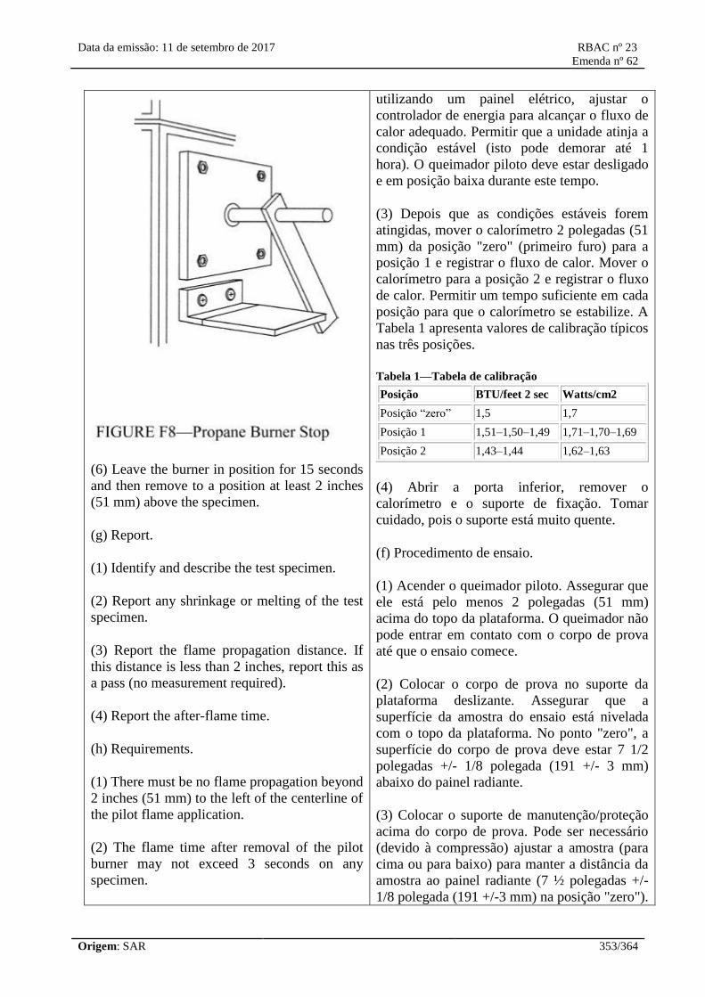
Data da emissão: 11 de setembro de 2017 RBAC nº 23
Emenda nº 62
Origem: SAR 353/364
(6) Leave the burner in position for 15 seconds
and then remove to a position at least 2 inches
(51 mm) above the specimen.
(g) Report.
(1) Identify and describe the test specimen.
(2) Report any shrinkage or melting of the test
specimen.
(3) Report the flame propagation distance. If
this distance is less than 2 inches, report this as
a pass (no measurement required).
(4) Report the after-flame time.
(h) Requirements.
(1) There must be no flame propagation beyond
2 inches (51 mm) to the left of the centerline of
the pilot flame application.
(2) The flame time after removal of the pilot
burner may not exceed 3 seconds on any
specimen.
utilizando um painel elétrico, ajustar o
controlador de energia para alcançar o fluxo de
calor adequado. Permitir que a unidade atinja a
condição estável (isto pode demorar até 1
hora). O queimador piloto deve estar desligado
e em posição baixa durante este tempo.
(3) Depois que as condições estáveis forem
atingidas, mover o calorímetro 2 polegadas (51
mm) da posição "zero" (primeiro furo) para a
posição 1 e registrar o fluxo de calor. Mover o
calorímetro para a posição 2 e registrar o fluxo
de calor. Permitir um tempo suficiente em cada
posição para que o calorímetro se estabilize. A
Tabela 1 apresenta valores de calibração típicos
nas três posições.
Tabela 1—Tabela de calibração
Posição BTU/feet 2 sec Watts/cm2
Posição “zero” 1,5 1,7
Posição 1 1,51–1,50–1,49 1,71–1,70–1,69
Posição 2 1,43–1,44 1,62–1,63
(4) Abrir a porta inferior, remover o
calorímetro e o suporte de fixação. Tomar
cuidado, pois o suporte está muito quente.
(f) Procedimento de ensaio.
(1) Acender o queimador piloto. Assegurar que
ele está pelo menos 2 polegadas (51 mm)
acima do topo da plataforma. O queimador não
pode entrar em contato com o corpo de prova
até que o ensaio comece.
(2) Colocar o corpo de prova no suporte da
plataforma deslizante. Assegurar que a
superfície da amostra do ensaio está nivelada
com o topo da plataforma. No ponto "zero", a
superfície do corpo de prova deve estar 7 1/2
polegadas +/- 1/8 polegada (191 +/- 3 mm)
abaixo do painel radiante.
(3) Colocar o suporte de manutenção/proteção
acima do corpo de prova. Pode ser necessário
(devido à compressão) ajustar a amostra (para
cima ou para baixo) para manter a distância da
amostra ao painel radiante (7 ½ polegadas +/-
1/8 polegada (191 +/-3 mm) na posição "zero").

Data da emissão: 11 de setembro de 2017 RBAC nº 23
Emenda nº 62
Origem: SAR 354/364
Na montagem do filme/fibra de vidro, é
fundamental fazer uma fenda na cobertura do
filme para purgar qualquer ar no interior. Isto
permite que o operador mantenha a posição
adequada do corpo de prova (nivelada com o
topo da plataforma) e permita a ventilação dos
gases durante o ensaio. Uma fenda
longitudinal, de aproximadamente 2 polegadas
(51 mm) no comprimento, deve ser centrada 3
polegadas +/- 1/2 polegada (76 mm +/- 13 mm)
a partir do flange esquerda da armação de
segurança. Uma faca de serviço é aceitável para
cortar a cobertura do filme.
(4) Imediatamente empurrar a plataforma
deslizante para a câmara e fechar a porta
inferior.
(5) Trazer a chama piloto do queimador em
contato com o centro do corpo de prova no
ponto "zero" e simultaneamente iniciar o
cronômetro. O queimador piloto deve estar em
um ângulo de 27° com a amostra e estar
aproximadamente 1/2 polegadas (12 mm)
acima da amostra. Ver figura F7. Um batente,
como mostrado na figura F8, permite que o
operador posicione o queimador corretamente a
cada vez.
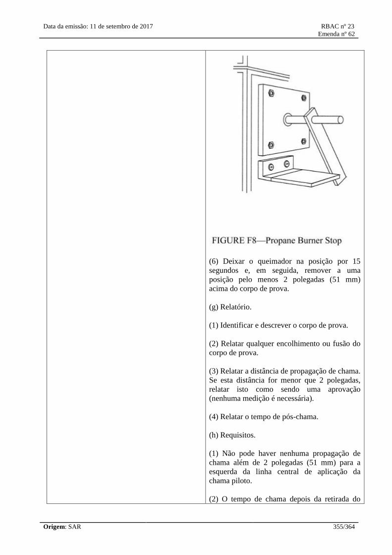
Data da emissão: 11 de setembro de 2017 RBAC nº 23
Emenda nº 62
Origem: SAR 355/364
(6) Deixar o queimador na posição por 15
segundos e, em seguida, remover a uma
posição pelo menos 2 polegadas (51 mm)
acima do corpo de prova.
(g) Relatório.
(1) Identificar e descrever o corpo de prova.
(2) Relatar qualquer encolhimento ou fusão do
corpo de prova.
(3) Relatar a distância de propagação de chama.
Se esta distância for menor que 2 polegadas,
relatar isto como sendo uma aprovação
(nenhuma medição é necessária).
(4) Relatar o tempo de pós-chama.
(h) Requisitos.
(1) Não pode haver nenhuma propagação de
chama além de 2 polegadas (51 mm) para a
esquerda da linha central de aplicação da
chama piloto.
(2) O tempo de chama depois da retirada do

Data da emissão: 11 de setembro de 2017 RBAC nº 23
Emenda nº 62
Origem: SAR 356/364
queimador piloto não pode exceder 3 segundos
em nenhum corpo de prova.
[Amdt. 23-23, 43 FR 50594, Oct. 30, 1978, as amended by Amdt. 23-34, 52 FR 1835, Jan. 15,
1987; 52 FR 34745, Sept. 14, 1987; Amdt. 23-49, 61 FR 5170, Feb. 9, 1996; Amdt. 23-62, 76 FR
75763, Dec. 2, 2011]
[Resolução nº 446, de 06.09.2017]
Appendix G to Part 23—Instructions for Continued Airworthiness
G23.1 General. (a) This appendix specifies requirements for the preparation of Instructions for
Continued Airworthiness as required by §23.1529.
(b) The Instructions for Continued Airworthiness for each airplane must include the Instructions for
Continued Airworthiness for each engine and propeller (hereinafter designated ‘products’), for each
appliance required by this chapter, and any required information relating to the interface of those
appliances and products with the airplane. If Instructions for Continued Airworthiness are not
supplied by the manufacturer of an appliance or product installed in the airplane, the Instructions for
Continued Airworthiness for the airplane must include the information essential to the continued
airworthiness of the airplane.
(c) The applicant must submit to the FAA a program to show how changes to the Instructions for
Continued Airworthiness made by the applicant or by the manufacturers of products and appliances
installed in the airplane will be distributed.
G23.2 Format. (a) The Instructions for Continued Airworthiness must be in the form of a manual
or manuals as appropriate for the quantity of data to be provided.
(b) The format of the manual or manuals must provide for a practical arrangement.
G23.3 Content. The contents of the manual or manuals must be prepared in the English language.
The Instructions for Continued Airworthiness must contain the following manuals or sections, as
appropriate, and information:
(a) Airplane maintenance manual or section. (1) Introduction information that includes an
explanation of the airplane's features and data to the extent necessary for maintenance or preventive
maintenance.
(2) A description of the airplane and its systems and installations including its engines, propellers,
and appliances.
(3) Basic control and operation information describing how the airplane components and systems
are controlled and how they operate, including any special procedures and limitations that apply.
(4) Servicing information that covers details regarding servicing points, capacities of tanks,
reservoirs, types of fluids to be used, pressures applicable to the various systems, location of access
panels for inspection and servicing, locations of lubrication points, lubricants to be used, equipment
required for servicing, tow instructions and limitations, mooring, jacking, and leveling information.

Data da emissão: 11 de setembro de 2017 RBAC nº 23
Emenda nº 62
Origem: SAR 357/364
(b) Maintenance instructions. (1) Scheduling information for each part of the airplane and its
engines, auxiliary power units, propellers, accessories, instruments, and equipment that provides the
recommended periods at which they should be cleaned, inspected, adjusted, tested, and lubricated,
and the degree of inspection, the applicable wear tolerances, and work recommended at these
periods. However, the applicant may refer to an accessory, instrument, or equipment manufacturer
as the source of this information if the applicant shows that the item has an exceptionally high
degree of complexity requiring specialized maintenance techniques, test equipment, or expertise.
The recommended overhaul periods and necessary cross reference to the Airworthiness Limitations
section of the manual must also be included. In addition, the applicant must include an inspection
program that includes the frequency and extent of the inspections necessary to provide for the
continued airworthiness of the airplane.
(2) Troubleshooting information describing probable malfunctions, how to recognize those
malfunctions, and the remedial action for those malfunctions.
(3) Information describing the order and method of removing and replacing products and parts with
any necessary precautions to be taken.
(4) Other general procedural instructions including procedures for system testing during ground
running, symmetry checks, weighing and determining the center of gravity, lifting and shoring, and
storage limitations.
(c) Diagrams of structural access plates and information needed to gain access for inspections when
access plates are not provided.
(d) Details for the application of special inspection techniques including radiographic and ultrasonic
testing where such processes are specified.
(e) Information needed to apply protective treatments to the structure after inspection.
(f) All data relative to structural fasteners such as identification, discard recommendations, and
torque values.
(g) A list of special tools needed.
(h) In addition, for commuter category airplanes, the following information must be furnished:
(1) Electrical loads applicable to the various systems;
(2) Methods of balancing control surfaces;
(3) Identification of primary and secondary structures; and
(4) Special repair methods applicable to the airplane.
G23.4 Airworthiness Limitations section. The Instructions for Continued Airworthiness must
contain a section titled Airworthiness Limitations that is segregated and clearly distinguishable
from the rest of the document. This section must set forth each mandatory replacement time,
structural inspection interval, and related structural inspection procedure required for type
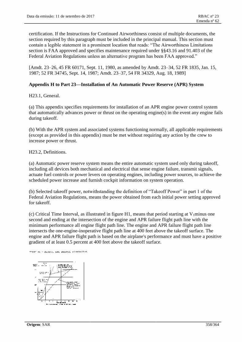
Data da emissão: 11 de setembro de 2017 RBAC nº 23
Emenda nº 62
Origem: SAR 358/364
certification. If the Instructions for Continued Airworthiness consist of multiple documents, the
section required by this paragraph must be included in the principal manual. This section must
contain a legible statement in a prominent location that reads: “The Airworthiness Limitations
section is FAA approved and specifies maintenance required under §§43.16 and 91.403 of the
Federal Aviation Regulations unless an alternative program has been FAA approved.”
[Amdt. 23–26, 45 FR 60171, Sept. 11, 1980, as amended by Amdt. 23–34, 52 FR 1835, Jan. 15,
1987; 52 FR 34745, Sept. 14, 1987; Amdt. 23–37, 54 FR 34329, Aug. 18, 1989]
Appendix H to Part 23—Installation of An Automatic Power Reserve (APR) System
H23.1, General.
(a) This appendix specifies requirements for installation of an APR engine power control system
that automatically advances power or thrust on the operating engine(s) in the event any engine fails
during takeoff.
(b) With the APR system and associated systems functioning normally, all applicable requirements
(except as provided in this appendix) must be met without requiring any action by the crew to
increase power or thrust.
H23.2, Definitions.
(a) Automatic power reserve system means the entire automatic system used only during takeoff,
including all devices both mechanical and electrical that sense engine failure, transmit signals,
actuate fuel controls or power levers on operating engines, including power sources, to achieve the
scheduled power increase and furnish cockpit information on system operation.
(b) Selected takeoff power, notwithstanding the definition of “Takeoff Power” in part 1 of the
Federal Aviation Regulations, means the power obtained from each initial power setting approved
for takeoff.
(c) Critical Time Interval, as illustrated in figure H1, means that period starting at V1minus one
second and ending at the intersection of the engine and APR failure flight path line with the
minimum performance all engine flight path line. The engine and APR failure flight path line
intersects the one-engine-inoperative flight path line at 400 feet above the takeoff surface. The
engine and APR failure flight path is based on the airplane's performance and must have a positive
gradient of at least 0.5 percent at 400 feet above the takeoff surface.

Data da emissão: 11 de setembro de 2017 RBAC nº 23
Emenda nº 62
Origem: SAR 359/364
H23.3, Reliability and performance requirements.
(a) It must be shown that, during the critical time interval, an APR failure that increases or does not
affect power on either engine will not create a hazard to the airplane, or it must be shown that such
failures are improbable.
(b) It must be shown that, during the critical time interval, there are no failure modes of the APR
system that would result in a failure that will decrease the power on either engine or it must be
shown that such failures are extremely improbable.
(c) It must be shown that, during the critical time interval, there will be no failure of the APR
system in combination with an engine failure or it must be shown that such failures are extremely
improbable.
(d) All applicable performance requirements must be met with an engine failure occurring at the
most critical point during takeoff with the APR system functioning normally.
H23.4, Power setting.
The selected takeoff power set on each engine at the beginning of the takeoff roll may not be less
than—
(a) The power necessary to attain, at V1, 90 percent of the maximum takeoff power approved for the
airplane for the existing conditions;
(b) That required to permit normal operation of all safety-related systems and equipment that are
dependent upon engine power or power lever position; and
(c) That shown to be free of hazardous engine response characteristics when power is advanced
from the selected takeoff power level to the maximum approved takeoff power.
H23.5, Powerplant controls—general.
(a) In addition to the requirements of §23.1141, no single failure or malfunction (or probable
combination thereof) of the APR, including associated systems, may cause the failure of any
powerplant function necessary for safety.
(b) The APR must be designed to—
(1) Provide a means to verify to the flight crew before takeoff that the APR is in an operating
condition to perform its intended function;
(2) Automatically advance power on the operating engines following an engine failure during
takeoff to achieve the maximum attainable takeoff power without exceeding engine operating
limits;
(3) Prevent deactivation of the APR by manual adjustment of the power levers following an engine
failure;

Data da emissão: 11 de setembro de 2017 RBAC nº 23
Emenda nº 62
Origem: SAR 360/364
(4) Provide a means for the flight crew to deactivate the automatic function. This means must be
designed to prevent inadvertent deactivation; and
(5) Allow normal manual decrease or increase in power up to the maximum takeoff power approved
for the airplane under the existing conditions through the use of power levers, as stated in
§23.1141(c), except as provided under paragraph (c) of H23.5 of this appendix.
(c) For airplanes equipped with limiters that automatically prevent engine operating limits from
being exceeded, other means may be used to increase the maximum level of power controlled by
the power levers in the event of an APR failure. The means must be located on or forward of the
power levers, must be easily identified and operated under all operating conditions by a single
action of any pilot with the hand that is normally used to actuate the power levers, and must meet
the requirements of §23.777 (a), (b), and (c).
H23.6, Powerplant instruments.
In addition to the requirements of §23.1305:
(a) A means must be provided to indicate when the APR is in the armed or ready condition.
(b) If the inherent flight characteristics of the airplane do not provide warning that an engine has
failed, a warning system independent of the APR must be provided to give the pilot a clear warning
of any engine failure during takeoff.
(c) Following an engine failure at V1or above, there must be means for the crew to readily and
quickly verify that the APR has operated satisfactorily.
[Doc. 26344, 58 FR 18979, Apr. 9, 1993]
Appendix I to Part 23—Seaplane Loads
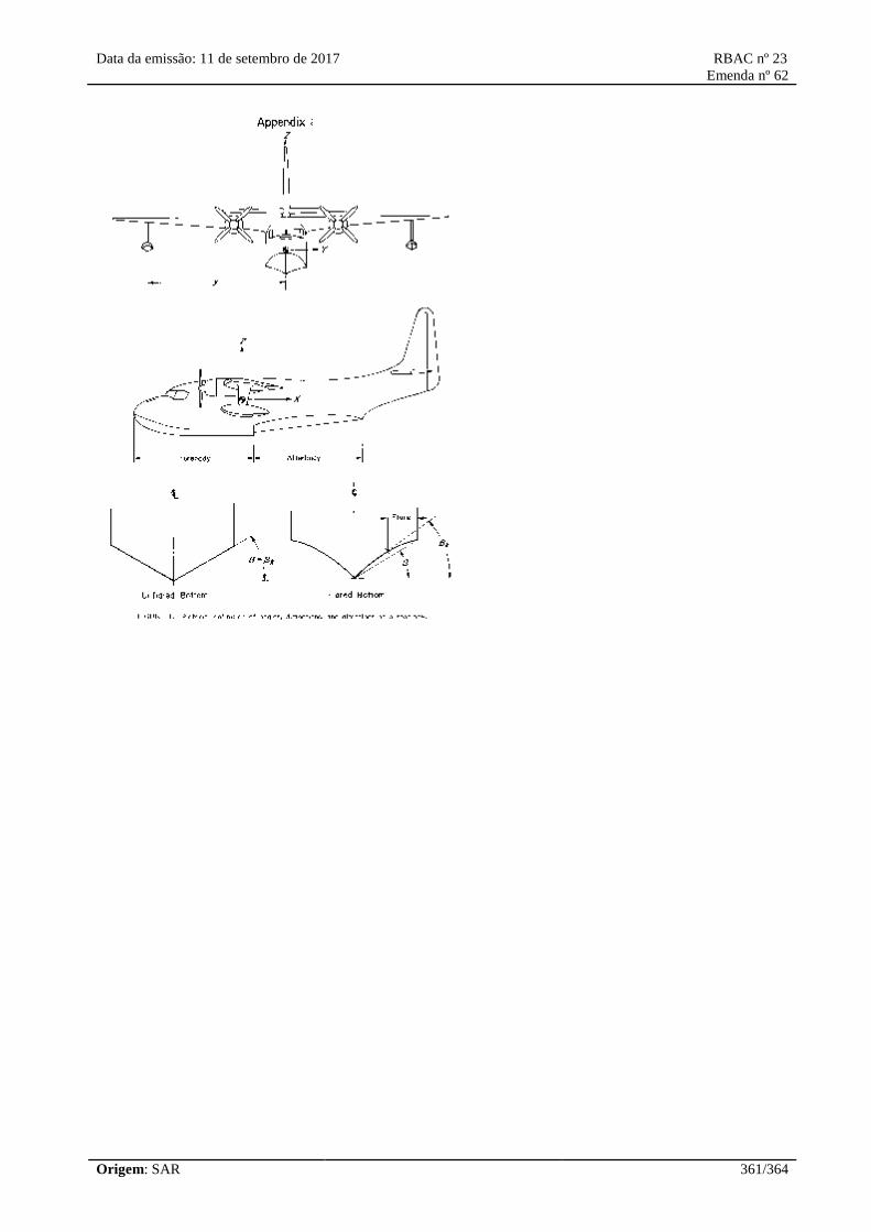
Data da emissão: 11 de setembro de 2017 RBAC nº 23
Emenda nº 62
Origem: SAR 361/364
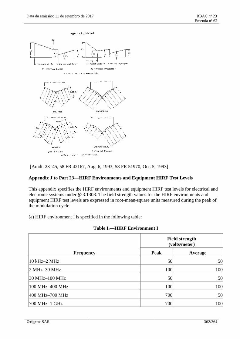
Data da emissão: 11 de setembro de 2017 RBAC nº 23
Emenda nº 62
Origem: SAR 362/364
[Amdt. 23–45, 58 FR 42167, Aug. 6, 1993; 58 FR 51970, Oct. 5, 1993]
Appendix J to Part 23—HIRF Environments and Equipment HIRF Test Levels
This appendix specifies the HIRF environments and equipment HIRF test levels for electrical and
electronic systems under §23.1308. The field strength values for the HIRF environments and
equipment HIRF test levels are expressed in root-mean-square units measured during the peak of
the modulation cycle.
(a) HIRF environment I is specified in the following table:
Table I.—HIRF Environment I
Frequency
Field strength
(volts/meter)
Peak Average
10 kHz–2 MHz 50 50
2 MHz–30 MHz 100 100
30 MHz–100 MHz 50 50
100 MHz–400 MHz 100 100
400 MHz–700 MHz 700 50
700 MHz–1 GHz 700 100

Data da emissão: 11 de setembro de 2017 RBAC nº 23
Emenda nº 62
Origem: SAR 363/364
GHz–2 GHz 2,000 200
2 GHz–6 GHz 3,000 200
6 GHz–8 GHz 1,000 200
8 GHz–12 GHz 3,000 300
12 GHz–18 GHz 2,000 200
18 GHz–40 GHz 600 200
In this table, the higher field strength applies at the frequency band edges.
(b) HIRF environment II is specified in the following table:
Table II.–HIRF Environment II
Frequency
Field strength
(volts/meter)
Peak Average
10 kHz–500 kHz 20 20
500 kHz–2 MHz 30 30
2 MHz–30 MHz 100 100
30 MHz–100 MHz 10 10
100 MHz–200 MHz 30 10
200 MHz–400 MHz 10 10
400 MHz–1 GHz 700 40
1 GHz–2 GHz 1,300 160
2 GHz–4 GHz 3,000 120
4 GHz–6 GHz 3,000 160
6 GHz–8 GHz 400 170
8 GHz–12 GHz 1,230 230
12 GHz–18 GHz 730 190
18 GHz–40 GHz 600 150
In this table, the higher field strength applies at the frequency band edges.
(c) Equipment HIRF Test Level 1.
(1) From 10 kilohertz (kHz) to 400 megahertz (MHz), use conducted susceptibility tests with

Data da emissão: 11 de setembro de 2017 RBAC nº 23
Emenda nº 62
Origem: SAR 364/364
continuous wave (CW) and 1 kHz square wave modulation with 90 percent depth or greater. The
conducted susceptibility current must start at a minimum of 0.6 milliamperes (mA) at 10 kHz,
increasing 20 decibels (dB) per frequency decade to a minimum of 30 mA at 500 kHz.
(2) From 500 kHz to 40 MHz, the conducted susceptibility current must be at least 30 mA.
(3) From 40 MHz to 400 MHz, use conducted susceptibility tests, starting at a minimum of 30 mA
at 40 MHz, decreasing 20 dB per frequency decade to a minimum of 3 mA at 400 MHz.
(4) From 100 MHz to 400 MHz, use radiated susceptibility tests at a minimum of 20 volts per meter
(V/m) peak with CW and 1 kHz square wave modulation with 90 percent depth or greater.
(5) From 400 MHz to 8 gigahertz (GHz), use radiated susceptibility tests at a minimum of 150 V/m
peak with pulse modulation of 4 percent duty cycle with a 1 kHz pulse repetition frequency. This
signal must be switched on and off at a rate of 1 Hz with a duty cycle of 50 percent.
(d) Equipment HIRF Test Level 2. Equipment HIRF test level 2 is HIRF environment II in table II
of this appendix reduced by acceptable aircraft transfer function and attenuation curves. Testing
must cover the frequency band of 10 kHz to 8 GHz.
(e) Equipment HIRF Test Level 3.
(1) From 10 kHz to 400 MHz, use conducted susceptibility tests, starting at a minimum of 0.15 mA
at 10 kHz, increasing 20 dB per frequency decade to a minimum of 7.5 mA at 500 kHz.
(2) From 500 kHz to 40 MHz, use conducted susceptibility tests at a minimum of 7.5 mA.
(3) From 40 MHz to 400 MHz, use conducted susceptibility tests, starting at a minimum of 7.5 mA
at 40 MHz, decreasing 20 dB per frequency decade to a minimum of 0.75 mA at 400 MHz.
(4) From 100 MHz to 8 GHz, use radiated susceptibility tests at a minimum of 5 V/m.
[Doc. No. FAA–2006–23657, 72 FR 44025, Aug. 6, 2007]