
ficha técnica do produto RUNTAL BRASIL (11) 2626-4645 ... · 13.2 A para 2 s trifásico 1.5 kW / 2...
12
ficha técnica do produto Características ATV71HU15M3Z INVERSOR DE FREQUENCIA 179A 90KW/125CV 380-480V TG FH CONFORMAL COATING principal Linha de produto Altivar 71 Tipo de produto ou componente Propulsor de velocidade variável Aplicação específica do produto Máquinas de alta potência, complexas Nome do componente ATV71 Alimentação do motor kW 0.75 kW em Ue 200..0,240 V monofásico 1.5 kW[Espaço]em[Espaço]200..0,240 V trifásico Alimentação do motor cv 1 hp em Ue 200..0,240 V monofásico 2 hp em 200..0,240 V trifásico Comprimento do cabo do motor Tensão nominal de fornecimento [Us] 200...240 V (- 15...10 %) Número de fases da rede Trifásico Monofásico Corrente da linha 11.3 A para 200 V trifásico 1.5 kW / 2 hp 12 A para 200 V monofásico 0.75 kW / 1 hp 9.6 A para 240 V trifásico 1.5 kW / 2 hp 9.9 A para 240 V monofásico 0.75 kW / 1 hp Filtro EMC Integrado Estilo de montagem Com dissipador Variante Sem terminal gráfico remoto Potência aparente 2.4 kVA em 240 V monofásico 0.75 kW / 1 hp 4 kVA em 240 V trifásico 1.5 kW / 2 hp Linha potencial Isc <= 5 kA trifásico <= 5 kA monofásico Corrente de saída nominal 4.8 A em 4 kHz 230 V monofásico 0.75 kW / 1 hp 8 A em 4 kHz 230 V trifásico 1.5 kW / 2 hp Corrente momentânea máxima 7.2 A para 60 s monofásico 0.75 kW / 1 hp 7.9 A para 2 s monofásico 0.75 kW / 1 hp 12 A para 60 s trifásico 1.5 kW / 2 hp 13.2 A para 2 s trifásico 1.5 kW / 2 hp Frequência de saída 0.1...599 Hz Frequência de comutação nominal 4 kHz Frequência de comutação 1..0,16 kHz ajustável 4..0,16 kHz com factor de degradação Perfil de controle de motor assíncrono Sistema ENA (adaptação de energia) para cargas desbalanceadas Controle de vetor de fluxo (FVC) com sensor (vetor de corrente) Controle de vetor de fluxo sem sensor (SFVC) (vetor de tensão ou corrente) Relação de frequência/tensão (2 ou 5 pontos) Tipo de polarização Sem impedância of Modbus Complementar Destino do produto Motores assíncronos Motores síncronos Limites de tensão de alimentação 170...264 V Frequência de alimentação 50..0,60 Hz (- 5...5 %) Frequência da rede 47,5...63 Hz Intervalo de velocidades 1...100 of motor assíncrono no modo de ciclo aberto, sem retorno de velocidade 1...50 of motor síncrono no modo de ciclo aberto, sem retorno de velocidade 1...1000 of motor assíncrono no modo de ciclo fechado com retorno do codificador Precisão da velocidade +/- 0,01% da velocidade nominal of 0,2 Tn a Tn variação de torque no modo de ciclo fechado com retorno do codificador As informações fornecidas neste documento contêm descrições gerais e / ou características técnicas do desempenho dos produtos. A intenção desse documento não é substituir e não deve ser usado para determinar a adequação ou confiabilidade destes produtos para aplicações específicas do usuário. É dever de qualquer usuário ou integrador realizar a análise de risco adequada e completa, avaliação e teste dos produtos no que diz respeito à aplicação específica relevante ou utilização. Nem a Schneider Electric, nem qualquer uma de suas filiais ou subsidiárias devem ser responsabilizadas pelo uso indevido das informações aqui contidas. 1 / 12 RUNTAL BRASIL (11) 2626-4645
Transcript of ficha técnica do produto RUNTAL BRASIL (11) 2626-4645 ... · 13.2 A para 2 s trifásico 1.5 kW / 2...
ficha técnica do produto
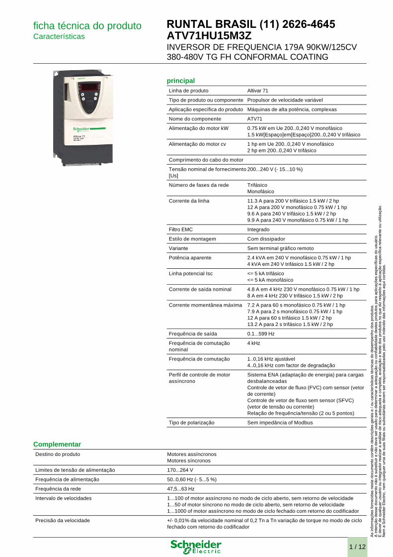
Características ATV71HU15M3Z
INVERSOR DE FREQUENCIA 179A 90KW/125CV 380-480V TG FH CONFORMAL COATING
principal Linha de produto Altivar 71
Tipo de produto ou componente Propulsor de velocidade variável
Aplicação específica do produto Máquinas de alta potência, complexas
Nome do componente ATV71
Alimentação do motor kW 0.75 kW em Ue 200..0,240 V monofásico 1.5 kW[Espaço]em[Espaço]200..0,240 V trifásico
Alimentação do motor cv 1 hp em Ue 200..0,240 V monofásico 2 hp em 200..0,240 V trifásico
Comprimento do cabo do motor
Tensão nominal de fornecimento [Us]
200...240 V (- 15...10 %)
Número de fases da rede Trifásico Monofásico
Corrente da linha 11.3 A para 200 V trifásico 1.5 kW / 2 hp 12 A para 200 V monofásico 0.75 kW / 1 hp 9.6 A para 240 V trifásico 1.5 kW / 2 hp 9.9 A para 240 V monofásico 0.75 kW / 1 hp
Filtro EMC Integrado
Estilo de montagem Com dissipador
Variante Sem terminal gráfico remoto
Potência aparente 2.4 kVA em 240 V monofásico 0.75 kW / 1 hp 4 kVA em 240 V trifásico 1.5 kW / 2 hp
Linha potencial Isc <= 5 kA trifásico <= 5 kA monofásico
Corrente de saída nominal 4.8 A em 4 kHz 230 V monofásico 0.75 kW / 1 hp 8 A em 4 kHz 230 V trifásico 1.5 kW / 2 hp
Corrente momentânea máxima 7.2 A para 60 s monofásico 0.75 kW / 1 hp 7.9 A para 2 s monofásico 0.75 kW / 1 hp 12 A para 60 s trifásico 1.5 kW / 2 hp 13.2 A para 2 s trifásico 1.5 kW / 2 hp
Frequência de saída 0.1...599 Hz
Frequência de comutação nominal
4 kHz
Frequência de comutação 1..0,16 kHz ajustável 4..0,16 kHz com factor de degradação
Perfil de controle de motor assíncrono
Sistema ENA (adaptação de energia) para cargas desbalanceadas Controle de vetor de fluxo (FVC) com sensor (vetor de corrente) Controle de vetor de fluxo sem sensor (SFVC) (vetor de tensão ou corrente) Relação de frequência/tensão (2 ou 5 pontos)
Tipo de polarização Sem impedância of Modbus
Complementar Destino do produto Motores assíncronos
Motores síncronos
Limites de tensão de alimentação 170...264 V
Frequência de alimentação 50..0,60 Hz (- 5...5 %)
Frequência da rede 47,5...63 Hz
Intervalo de velocidades 1...100 of motor assíncrono no modo de ciclo aberto, sem retorno de velocidade 1...50 of motor síncrono no modo de ciclo aberto, sem retorno de velocidade 1...1000 of motor assíncrono no modo de ciclo fechado com retorno do codificador
Precisão da velocidade +/- 0,01% da velocidade nominal of 0,2 Tn a Tn variação de torque no modo de ciclo fechado com retorno do codificador
As
info
rmaç
ões
forn
ecid
as n
este
doc
umen
to c
ontê
m d
escr
içõe
s ge
rais
e /
ou c
arac
terís
ticas
técn
icas
do
dese
mpe
nho
dos
prod
utos
.A
inte
nção
des
se d
ocum
ento
não
é s
ubst
ituir
e nã
o de
ve s
er u
sado
par
a de
term
inar
a a
dequ
ação
ou
conf
iabi
lidad
e de
stes
pro
duto
s pa
ra a
plic
açõe
s es
pecí
ficas
do
usuá
rio.
É d
ever
de
qual
quer
usu
ário
ou
inte
grad
or re
aliz
ar a
aná
lise
de ri
sco
adeq
uada
e c
ompl
eta,
ava
liaçã
o e
test
e do
s pr
odut
os n
o qu
e di
z re
spei
to à
apl
icaç
ão e
spec
ífica
rele
vant
e ou
util
izaç
ão.
Nem
a S
chne
ider
Ele
ctric
, nem
qua
lque
r um
a de
sua
s fil
iais
ou
subs
idiá
rias
deve
m s
er re
spon
sabi
lizad
as p
elo
uso
inde
vido
das
info
rmaç
ões
aqui
con
tidas
.
1 / 12
RUNTAL BRASIL (11) 2626-4645
+/- 10% do deslize nominal of 0,2 Tn a Tn variação de torque sem retorno de velocidade
Precisão de torque +/- 15 % no modo de ciclo aberto, sem retorno de velocidade +/- 5 % no modo de ciclo fechado com retorno do codificador
Sobretorque temporário 220 % do torque nominal do motor +/- 10 % para 2 s 170 % do torque nominal do motor +/- 10 % para 60 s a cada 10 minutos
Torque de frenagem <= 150 % with braking or hoist resistor 30 % without braking resistor
Perfil de controle de motor síncrono Controle de vetor sem retorno de velocidade
Retorno de regulamento Regulador PI ajustável
Compensação da diferença de velocidade do motor Ajustável Automático seja qual for a carga Não disponível na relação de tensão/frequência (2 ou 5 pontos) Suprimível
Sinalização local 1 LED vermelho presença de tensão da unidade
Tensão de saída <= tensão da fonte de alimentação
Isolamento Elétrico entre a potência e o controle
Tipo de cabo Com kit NEMA Tipo 1 : 3-filamento cabo 508 UL em 40 °C, cobre 75 °C PVC Com um kit IP21 ou IP31 : 3-filamento cabo IEC em 40 °C, cobre 70 °C PVC Sem kit de montagem : 1-filamento cabo IEC a 45 °C, cobre 70 °C PVC Sem kit de montagem : 1-filamento cabo IEC a 45 °C, cobre 90 °C XLPE/EPR
Conexão elétrica EA-/EA1+, EA2, SA1, R1A, R1B, R1C, R2A, R2B, LI1...LI6, ENER terminal 2,5 mm² / AWG 14 L1/R, L2/S, L3/T, U/T1, V/T2, W/T3, PC/-, PO, PA/+, PA, PB terminal 4 mm² / AWG 10
Torque de aperto EA-/EA1+, EA2, SA1, R1A, R1B, R1C, R2A, R2B, LI1...LI6, ENER 0.6 N.m L1/R, L2/S, L3/T, U/T1, V/T2, W/T3, PC/-, PO, PA/+, PA, PB 1.4 N.m / 12,3 lb.pol
Alimentação Alimentação interna para potenciômetro de referência (1 a 10 kOhms), 10,5 V CC +/- 5 %, <= 10 mA para proteção contra sobrecargas e curtos-circuitos Alimentação interna 24 V CC , limites de tensão 21...27 V <= 200 mA para proteção contra sobrecargas e curtos-circuitos
Número de entrada analógica 2
Tipo da entrada analógica EA1-/EA1+ tensão diferencial bipolar +/- 10 V CC, Tensão de entrada 24 V máx., Resolução 11 bits + sinal EA2 corrente configurável através de software 0..0,20 mA , impedância 242 Ohm, resolução 11 bits EA2 tensão configurável através de software 0..0,10 V CC, tensão de entrada 24 V máx., impedância 30000 Ohm, resolução 11 bits
Duração de amostra EA1-/EA1+ 2 ms, +/- 0,5 ms[Espaço]para[Espaço]analógico entrada(s) EA2 2 ms, +/- 0,5 ms[Espaço]para[Espaço]analógico entrada(s) LI1...LI5 2 ms, +/- 0,5 ms[Espaço]para[Espaço]digital entrada(s) LI6 (se configurado como entrada lógica) 2 ms, +/- 0,5 ms para digital entrada(s)
Tempo de resposta <= 100 ms no STO (Desligamento Seguro do Torque) SA1 2 ms, Tolerância +/- 0,5 ms of analógico saída(s) R1A, R1B, R1C 7 ms, Tolerância +/- 0,5 ms of digital saída(s) R2A, R2B 7 ms, Tolerância +/- 0,5 ms of digital saída(s)
Precisão EA1-/EA1+ +/- 0.6 % para uma variação de temperatura de 60 °C EA2 +/- 0.6 % para uma variação de temperatura de 60 °C SA1 +/- 1 % para uma variação de temperatura de 60 °C
Erro de linearidade EA1-/EA1+, EA2 +/- 0,15% do valor máximo SA1 +/- 0.2 %
Número de saída analógica 1
Tipo da saída analógica SA1 corrente configurável através de software 0..0,20 mA , impedância 500 Ohm, resolução 10 bits SA1 saída lógica configurável por software 10 V <= 20 mA SA1 tensão configurável através de software 0..0,10 V CC , impedância 470 Ohm, resolução 10 bits
Número de saída digital 2
Tipo de saída digital R1A, R1B, R1C lógica do relé configurável NA/NF, durabilidade elétrica 100000 cycles R2A, R2B lógica do relé configurável não, durabilidade elétrica 100000 cycles
Corrente de comutação mínima Lógica do relé configurável 3 mA a 24 V CC
Corrente de comutação máxima R1, R2 ligar resistivo carga, 5 A em 250 V CA, cos phi = 1, R1, R2 ligar resistivo carga, 5 A em 30 V CC, cos phi = 1, R1, R2 ligar indutivo carga, 2 A em 250 V CA, cos phi = 0,4, R1, R2 ligar indutivo carga, 2 A em 30 V CC, cos phi = 0,4,
Número de entrada digital 7
Tipo de entrada digital LI6 : configurável por interruptor 24 V CC com PLC de nível 1, impedância: 3500 Ohm
2 / 12
ENER : entrada de segurança 24 V CC, impedância: 1500 Ohm em conformidade com ISO 13849-1 nível d LI1...LI5 : programável 24 V CC com PLC de nível 1, impedância: 3500 Ohm LI6 : sonda PTC configurável por interruptor 0...6, impedância: 1500 Ohm
Lógica de entrada digital LI1...LI5 lógica positiva (fonte) < 5 V (estado 0)> 11 V (estado 0) LI1...LI5 lógica negativa (coletor) > 16 V (estado 0)< 10 V (estado 0) LI6 (se configurado como entrada lógica) lógica positiva (fonte), < 5 V (estado 0), > 11 V (estado 0) LI6 (se configurado como entrada lógica) lógica negativa (coletor), > 16 V (estado 0), < 10 V (estado 0)
Rampas de aceleração e desaceleração Adaptação auto. da rampa se excedido o poder de frenagem, através da resistência Linear ajustável separadamente de 0,01 a 9000 s S, U ou personalizado
Frenagem até à paralisação Por injeção CC
Tipo de proteção Unidade contra ultrapassagem do limite de velocidade Unidade contra perda de fase de entrada Unidade abertura no circuito de controle Unidade interrupções da fase de entrada Unidade sobretensão de linha de alimentação Unidade subtensão de alimentação de linha Unidade sobrecorrente entre fases de saída e terra Unidade proteção contra sobreaquecimento Unidade sobretensões no barramento CC Unidade curto-circuito entre fases do motor Unidade proteção térmica Motor interrupção da fase do motor Motor remoção de potência Motor proteção térmica
Resistência de isolamento > 1 MOhm a 500 V CC em 1 minuto à terra
Resolução de frequência Entrada analógica 0,024/50 Hz Unidade visor 0,1 Hz
Protocolo da porta de comunicação CANopen Modbus
Tipo de conector 1 RJ45 of Modbus na face frontal 1 RJ45 of Modbus no terminal SUB-D 9 macho em RJ45 of CANopen
Interface física 2 fios RS 485 of Modbus
Estrutura de transmissão RTU of Modbus
Taxa de transmissão 20 kbps, 50 kbps, 125 kbps, 250 kbps, 500 kbps, 1 Mbps of CANopen 4800 bps:; 9600 bps; 19200 bps; 38,4 Kbps of Modbus no terminal 9600 bps, 19200 bps of Modbus na face frontal
Formato de dados 8 bits, 1 paragem, paridade par of Modbus na face frontal 8 bits, ímpar, par ou paridade não configurável of Modbus no terminal
Número de endereços 1...247 of Modbus 1...127 of CANopen
Método de acesso Slave of CANopen
Sinalização CE
Posição de funcionamento Vertical +/- 10 graus
Altura 230 mm
Profundidade 175 mm
Largura 130 mm
Peso do produto 3 kg
Placa de opção CC-Link placa de comunicação Controlador dentro da placa programável DeviceNet placa de comunicação Ethernet/IP placa de comunicação Fipio placa de comunicação Placa de extensão de E/S Interbus-S placa de comunicação Placa de interface para codificador Modbus Plus placa de comunicação Modbus TCP placa de comunicação Modbus/Uni-Telway placa de comunicação Placa para grua suspensa Profibus DP placa de comunicação Profibus DP V1 placa de comunicação
Ambiente
3 / 12

nível de ruído 43 dB para 86/188/CEE
força dielétrica 2830 V CC entre a terra e os terminais de alimentação 4230 V CC entre os terminais de controle e de alimentação
compatibilidade eletromagnética Teste de imunidade de radiofrequência conduzida para IEC 61000-4-6 nível 3 Teste de imunidade a rajadas/momentâneas elétricas rápidas para IEC 61000-4-4 nível 4 Teste de imunidade de descarga eletrostática para IEC 61000-4-2 nível 3 Teste de imunidade ao campo eletromagnético de radiofrequência com radiação para IEC 61000-4-3 nível 3 Teste de imunidade contra quedas e interrupções da tensão para IEC 61000-4-11 1,2/50 µs - 8/20 µs teste de imunidade contra sobretensão para IEC 61000-4-5 nível 3
padrões EN 55011, classe A, grupo 1 EN 61800-3, ambientes 1, categoria C2 EN 61800-3, ambientes 2, categoria C2 EN/IEC 61800-3 EN/IEC 61800-5-1 IEC 60721-3-3 classe 3C1 IEC 60721-3-3 classe 3S2 UL Tipo 1
certificações do produto CSA C-Tick GOST NOM 117 UL
graus de poluição 2 para EN/IEC 61800-5-1
grau de proteção IP IP20 na parte mais alta sem placa de vedação na cobertura para EN/IEC 60529 IP20 na parte mais alta sem placa de vedação na cobertura para EN/IEC 61800-5-1 IP21 para EN/IEC 60529 IP21 para EN/IEC 61800-5-1 IP41 na parte mais alta para EN/IEC 60529 IP41 na parte mais alta para EN/IEC 61800-5-1 IP54 na parte mais baixa para EN/IEC 60529 IP54 na parte mais baixa para EN/IEC 61800-5-1
resistência à vibração 1,5 mm pico-a-pico (f = 3...13 Hz) para EN/IEC 60068-2-6 1 gn (f = 13...200 Hz) para EN/IEC 60068-2-6
resistência ao choque 15 gn of 11 ms para EN/IEC 60068-2-27
umidade relativa 5...95 % sem condensação para IEC 60068-2-3 5...95 % sem goteiras para IEC 60068-2-3
temperatura ambiente do ar para funcionamento -10...50 °C sem degradação
temperatura ambiente do ar para armazenamento -25...70 °C
altitude de funcionamento <= 1000 m sem degradação 1000...3000 m com degradação de corrente de 1% por 100 m
Contractual warranty Período 18 meses
Variable Speed Drives without Graphic Display Terminal
Dimensions without Option Card
Dimensions in mm
Dimensions in in.
a b c G H K Ø
130 230 149 113.5 220 5 5
4 / 12

Dimensions with 1 Option Card (1)
Dimensions in mm
Dimensions in in.
(1) Option cards: I/O extension cards, communication cards or "Controller Inside” programmable card.
Dimensions with 2 Option Cards (1)
Dimensions in mm
Dimensions in in.
(1) Option cards: I/O extension cards, communication cards or "Controller Inside” programmable card. Mounting Recommendations
Depending on the conditions in which the drive is to be used, its installation will require certain precautions and the use of appropriate accessories.
Install the unit vertically:
● Avoid placing it close to heating elements
● Leave sufficient free space to ensure that the air required for cooling purposes can circulate from the bottom to the top of the unit.
Clearance
a b c G H K Ø
5.11 9.05 5.86 4.46 8.66 0.19 0.19
a c1 G H K Ø
130 172 113.5 220 5 5
a c1 G H K Ø
5.11 6.77 4.46 8.66 0.19 0.19
a c2 G H K Ø
130 195 113.5 220 5 5
a c2 G H K Ø
5.11 7.68 4.46 8.66 0.19 0.19
5 / 12
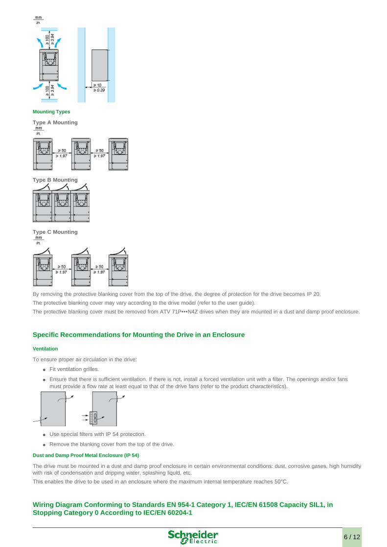
Mounting Types
Type A Mounting
Type B Mounting
Type C Mounting
By removing the protective blanking cover from the top of the drive, the degree of protection for the drive becomes IP 20.
The protective blanking cover may vary according to the drive model (refer to the user guide).
The protective blanking cover must be removed from ATV 71P•••N4Z drives when they are mounted in a dust and damp proof enclosure. Specific Recommendations for Mounting the Drive in an Enclosure
Ventilation
To ensure proper air circulation in the drive:
● Fit ventilation grilles.
● Ensure that there is sufficient ventilation. If there is not, install a forced ventilation unit with a filter. The openings and/or fans must provide a flow rate at least equal to that of the drive fans (refer to the product characteristics).
● Use special filters with IP 54 protection.
● Remove the blanking cover from the top of the drive.
Dust and Damp Proof Metal Enclosure (IP 54)
The drive must be mounted in a dust and damp proof enclosure in certain environmental conditions: dust, corrosive gases, high humidity with risk of condensation and dripping water, splashing liquid, etc.
This enables the drive to be used in an enclosure where the maximum internal temperature reaches 50°C. Wiring Diagram Conforming to Standards EN 954-1 Category 1, IEC/EN 61508 Capacity SIL1, in Stopping Category 0 According to IEC/EN 60204-1
6 / 12
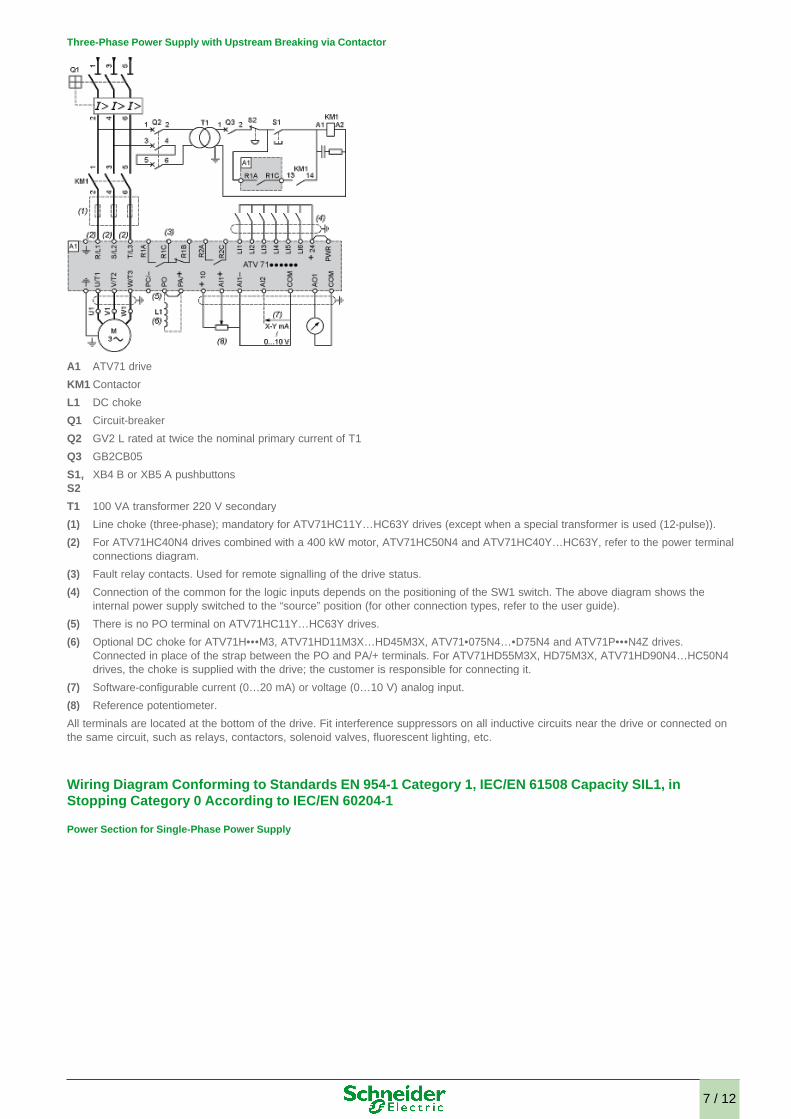
Three-Phase Power Supply with Upstream Breaking via Contactor
All terminals are located at the bottom of the drive. Fit interference suppressors on all inductive circuits near the drive or connected on the same circuit, such as relays, contactors, solenoid valves, fluorescent lighting, etc. Wiring Diagram Conforming to Standards EN 954-1 Category 1, IEC/EN 61508 Capacity SIL1, in Stopping Category 0 According to IEC/EN 60204-1
Power Section for Single-Phase Power Supply
A1 ATV71 drive
KM1 Contactor
L1 DC choke
Q1 Circuit-breaker
Q2 GV2 L rated at twice the nominal primary current of T1
Q3 GB2CB05
S1, S2
XB4 B or XB5 A pushbuttons
T1 100 VA transformer 220 V secondary
(1) Line choke (three-phase); mandatory for ATV71HC11Y…HC63Y drives (except when a special transformer is used (12-pulse)).
(2) For ATV71HC40N4 drives combined with a 400 kW motor, ATV71HC50N4 and ATV71HC40Y…HC63Y, refer to the power terminal connections diagram.
(3) Fault relay contacts. Used for remote signalling of the drive status.
(4) Connection of the common for the logic inputs depends on the positioning of the SW1 switch. The above diagram shows the internal power supply switched to the “source” position (for other connection types, refer to the user guide).
(5) There is no PO terminal on ATV71HC11Y…HC63Y drives.
(6) Optional DC choke for ATV71H•••M3, ATV71HD11M3X…HD45M3X, ATV71•075N4…•D75N4 and ATV71P•••N4Z drives. Connected in place of the strap between the PO and PA/+ terminals. For ATV71HD55M3X, HD75M3X, ATV71HD90N4…HC50N4 drives, the choke is supplied with the drive; the customer is responsible for connecting it.
(7) Software-configurable current (0…20 mA) or voltage (0…10 V) analog input.
(8) Reference potentiometer.
7 / 12
All terminals are located at the bottom of the drive. Fit interference suppressors on all inductive circuits near the drive or connected on the same circuit, such as relays, contactors, solenoid valves, fluorescent lighting, etc. Wiring Diagram Conforming to Standards EN 954-1 Category 1, IEC/EN 61508 Capacity SIL1, in Stopping Category 0 According to IEC/EN 60204-1
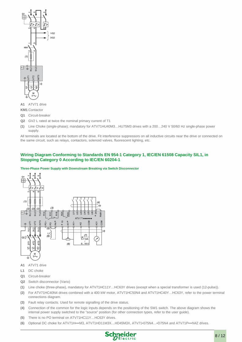
Three-Phase Power Supply with Downstream Breaking via Switch Disconnector
A1 ATV71 drive
KM1 Contactor
Q1 Circuit-breaker
Q2 GV2 L rated at twice the nominal primary current of T1
(1) Line Choke (single-phase); mandatory for ATV71HU40M3…HU75M3 drives with a 200…240 V 50/60 Hz single-phase power supply.
A1 ATV71 drive
L1 DC choke
Q1 Circuit-breaker
Q2 Switch disconnector (Vario)
(1) Line choke (three-phase), mandatory for ATV71HC11Y…HC63Y drives (except when a special transformer is used (12-pulse)).
(2) For ATV71HC40N4 drives combined with a 400 kW motor, ATV71HC50N4 and ATV71HC40Y…HC63Y, refer to the power terminal connections diagram.
(3) Fault relay contacts. Used for remote signalling of the drive status.
(4) Connection of the common for the logic inputs depends on the positioning of the SW1 switch. The above diagram shows the internal power supply switched to the “source” position (for other connection types, refer to the user guide).
(5) There is no PO terminal on ATV71HC11Y…HC63Y drives.
(6) Optional DC choke for ATV71H•••M3, ATV71HD11M3X…HD45M3X, ATV71•075N4…•D75N4 and ATV71P•••N4Z drives.
8 / 12
All terminals are located at the bottom of the drive. Fit interference suppressors on all inductive circuits near the drive or connected on the same circuit, such as relays, contactors, solenoid valves, fluorescent lighting, etc. Wiring Diagram Conforming to Standards EN 954-1 Category 1, IEC/EN 61508 Capacity SIL1, in Stopping Category 0 According to IEC/EN 60204-1
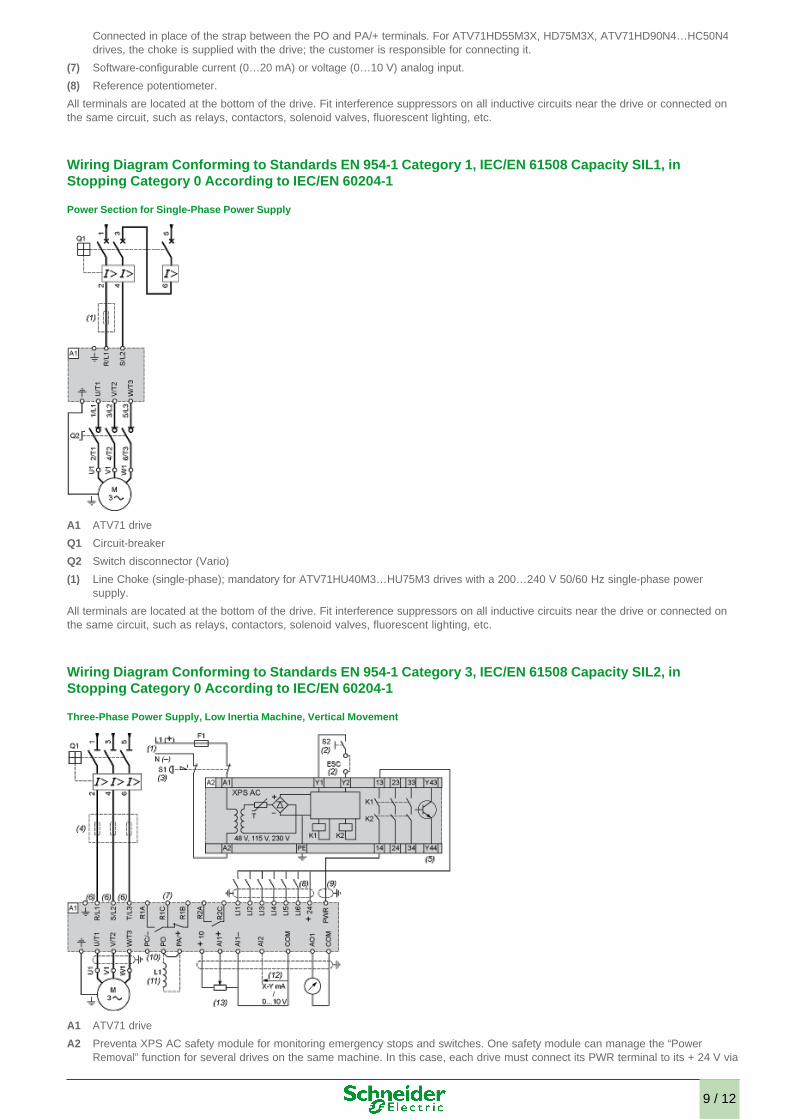
Power Section for Single-Phase Power Supply
All terminals are located at the bottom of the drive. Fit interference suppressors on all inductive circuits near the drive or connected on the same circuit, such as relays, contactors, solenoid valves, fluorescent lighting, etc. Wiring Diagram Conforming to Standards EN 954-1 Category 3, IEC/EN 61508 Capacity SIL2, in Stopping Category 0 According to IEC/EN 60204-1
Three-Phase Power Supply, Low Inertia Machine, Vertical Movement
Connected in place of the strap between the PO and PA/+ terminals. For ATV71HD55M3X, HD75M3X, ATV71HD90N4…HC50N4 drives, the choke is supplied with the drive; the customer is responsible for connecting it.
(7) Software-configurable current (0…20 mA) or voltage (0…10 V) analog input.
(8) Reference potentiometer.
A1 ATV71 drive
Q1 Circuit-breaker
Q2 Switch disconnector (Vario)
(1) Line Choke (single-phase); mandatory for ATV71HU40M3…HU75M3 drives with a 200…240 V 50/60 Hz single-phase power supply.
A1 ATV71 drive
A2 Preventa XPS AC safety module for monitoring emergency stops and switches. One safety module can manage the “Power Removal” function for several drives on the same machine. In this case, each drive must connect its PWR terminal to its + 24 V via
9 / 12
All terminals are located at the bottom of the drive. Fit interference suppressors on all inductive circuits near the drive or connected on the same circuit, such as relays, contactors, solenoid valves, fluorescent lighting, etc. Wiring Diagram Conforming to Standards EN 954-1 Category 3, IEC/EN 61508 Capacity SIL2, in Stopping Category 0 According to IEC/EN 60204-1
Power Section for Single-Phase Power Supply
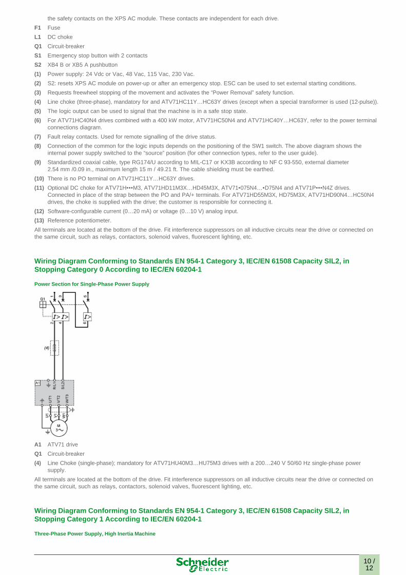
All terminals are located at the bottom of the drive. Fit interference suppressors on all inductive circuits near the drive or connected on the same circuit, such as relays, contactors, solenoid valves, fluorescent lighting, etc. Wiring Diagram Conforming to Standards EN 954-1 Category 3, IEC/EN 61508 Capacity SIL2, in Stopping Category 1 According to IEC/EN 60204-1
Three-Phase Power Supply, High Inertia Machine
the safety contacts on the XPS AC module. These contacts are independent for each drive.
F1 Fuse
L1 DC choke
Q1 Circuit-breaker
S1 Emergency stop button with 2 contacts
S2 XB4 B or XB5 A pushbutton
(1) Power supply: 24 Vdc or Vac, 48 Vac, 115 Vac, 230 Vac.
(2) S2: resets XPS AC module on power-up or after an emergency stop. ESC can be used to set external starting conditions.
(3) Requests freewheel stopping of the movement and activates the “Power Removal” safety function.
(4) Line choke (three-phase), mandatory for and ATV71HC11Y…HC63Y drives (except when a special transformer is used (12-pulse)).
(5) The logic output can be used to signal that the machine is in a safe stop state.
(6) For ATV71HC40N4 drives combined with a 400 kW motor, ATV71HC50N4 and ATV71HC40Y…HC63Y, refer to the power terminal connections diagram.
(7) Fault relay contacts. Used for remote signalling of the drive status.
(8) Connection of the common for the logic inputs depends on the positioning of the SW1 switch. The above diagram shows the internal power supply switched to the “source” position (for other connection types, refer to the user guide).
(9) Standardized coaxial cable, type RG174/U according to MIL-C17 or KX3B according to NF C 93-550, external diameter 2.54 mm /0.09 in., maximum length 15 m / 49.21 ft. The cable shielding must be earthed.
(10) There is no PO terminal on ATV71HC11Y…HC63Y drives.
(11) Optional DC choke for ATV71H•••M3, ATV71HD11M3X…HD45M3X, ATV71•075N4…•D75N4 and ATV71P•••N4Z drives. Connected in place of the strap between the PO and PA/+ terminals. For ATV71HD55M3X, HD75M3X, ATV71HD90N4…HC50N4 drives, the choke is supplied with the drive; the customer is responsible for connecting it.
(12) Software-configurable current (0…20 mA) or voltage (0…10 V) analog input.
(13) Reference potentiometer.
A1 ATV71 drive
Q1 Circuit-breaker
(4) Line Choke (single-phase); mandatory for ATV71HU40M3…HU75M3 drives with a 200…240 V 50/60 Hz single-phase power supply.
10 /12
All terminals are located at the bottom of the drive. Fit interference suppressors on all inductive circuits near the drive or connected on the same circuit, such as relays, contactors, solenoid valves, fluorescent lighting, etc. Wiring Diagram Conforming to Standards EN 954-1 Category 3, IEC/EN 61508 Capacity SIL2, in Stopping Category 1 According to IEC/EN 60204-1
Power Section for Single-Phase Power Supply
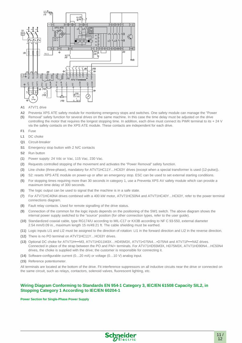
A1 ATV71 drive
A2 (5)
Preventa XPS ATE safety module for monitoring emergency stops and switches. One safety module can manage the "Power Removal” safety function for several drives on the same machine. In this case the time delay must be adjusted on the drive controlling the motor that requires the longest stopping time. In addition, each drive must connect its PWR terminal to its + 24 V via the safety contacts on the XPS ATE module. These contacts are independent for each drive.
F1 Fuse
L1 DC choke
Q1 Circuit-breaker
S1 Emergency stop button with 2 N/C contacts
S2 Run button
(1) Power supply: 24 Vdc or Vac, 115 Vac, 230 Vac.
(2) Requests controlled stopping of the movement and activates the “Power Removal” safety function.
(3) Line choke (three-phase), mandatory for ATV71HC11Y…HC63Y drives (except when a special transformer is used (12-pulse)).
(4) S2: resets XPS ATE module on power-up or after an emergency stop. ESC can be used to set external starting conditions.
(5) For stopping times requiring more than 30 seconds in category 1, use a Preventa XPS AV safety module which can provide a maximum time delay of 300 seconds.
(6) The logic output can be used to signal that the machine is in a safe state.
(7) For ATV71HC40N4 drives combined with a 400 kW motor, ATV71HC50N4 and ATV71HC40Y…HC63Y, refer to the power terminal connections diagram.
(8) Fault relay contacts. Used for remote signalling of the drive status.
(9) Connection of the common for the logic inputs depends on the positioning of the SW1 switch. The above diagram shows the internal power supply switched to the “source” position (for other connection types, refer to the user guide).
(10) Standardized coaxial cable, type RG174/U according to MIL-C17 or KX3B according to NF C 93-550, external diameter 2.54 mm/0.09 in., maximum length 15 m/49.21 ft. The cable shielding must be earthed.
(11) Logic inputs LI1 and LI2 must be assigned to the direction of rotation: LI1 in the forward direction and LI2 in the reverse direction.
(12) There is no PO terminal on ATV71HC11Y…HC63Y drives.
(13) Optional DC choke for ATV71H•••M3, ATV71HD11M3X…HD45M3X, ATV71•075N4…•D75N4 and ATV71P•••N4Z drives. Connected in place of the strap between the PO and PA/+ terminals. For ATV71HD55M3X, HD75M3X, ATV71HD90N4…HC50N4 drives, the choke is supplied with the drive; the customer is responsible for connecting it.
(14) Software-configurable current (0…20 mA) or voltage (0…10 V) analog input.
(15) Reference potentiometer.
11 /12

All terminals are located at the bottom of the drive. Fit interference suppressors on all inductive circuits near the drive or connected on the same circuit, such as relays, contactors, solenoid valves, fluorescent lighting, etc. Derating Curves
The derating curves for the drive nominal current (In) depend on the temperature, the switching frequency and the mounting type. For intermediate temperatures (e.g. 55°C), interpolate between 2 curves.
A1 ATV71 drive
Q1 Circuit-breaker
(3) Line Choke (single-phase); mandatory for ATV71HU40M3…HU75M3 drives with a 200…240 V 50/60 Hz single-phase power supply.
X Switching frequency
(1) Mounting type
12 /12