Bem-vindos a Organização e Arquitetura de … · ִNão será permitido ver a prova para decidir...
44
Bem-vindos a Organização e Arquitetura de Computadores II Fabiano Hessel & Ney Calazans http://www.inf.pucrs.br/~hessel http://www.inf.pucrs.br/~calazans
Transcript of Bem-vindos a Organização e Arquitetura de … · ִNão será permitido ver a prova para decidir...

Bem-vindos a Organização e Arquitetura
de Computadores II
Fabiano Hessel & Ney Calazanshttp://www.inf.pucrs.br/~hessel
http://www.inf.pucrs.br/~calazans

Informações
Atendimento (dúvidas, provas, trabalhos): Marcar hora ([email protected])Marcar hora ([email protected])Marcar hora ([email protected])Monitor: ...

Informações - Continuação� Material disponível na página da disciplina e no Moodle� Trabalhos serão entregues no Moodle� Provas
Nenhum aluno poderá sair da sala de prova antes de assinar a ata de presença.ata de presença.
Não será permitido ver a prova para decidir se vai fazer ou não. Depois que o 1o. aluno recebeu a prova, os demais só poderão sair depois de assinar a ata de presença
Não será permitida a entrada de alunos após a saída do 1o. aluno. Recomenda-se que o 1o. aluno saia após decorridos 30 min. de prova.
As provas são com consulta (P1, P2, P4 e G2). Não será permitido o uso de celulares, PDAs, Palms, Laptops ou assemelhados durante a prova.


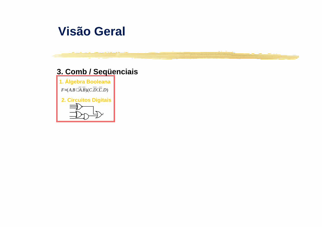
Visão Geral
)..(.)..( DCDCBABAF ++=
1. Álgebra Booleana

F
)..(.)..( DCDCBABAF ++=
1. Álgebra Booleana
2. Circuitos Digitais
Visão Geral
F
F
)..(.)..( DCDCBABAF ++=
1. Álgebra Booleana
2. Circuitos Digitais
3. Comb / Seqüenciais
Visão Geral
F

++=
1. Álgebra Booleana
3. Comb / Seqüenciais
4. Bloco de Dados
++=
1. Álgebra Booleana
3. Comb / Seqüenciais
4. Bloco de ControleModelo Von Neumann
Visão Geral
F
)..(.)..( DCDCBABAF ++=
2. Circuitos Digitais
F
)..(.)..( DCDCBABAF ++=
2. Circuitos Digitais

3. Comb / Seqüenciais
4. Bloco de Dados
3. Comb / Seqüenciais
4. Bloco de Controle
Modelo Von Neumann
5. Arquitetura
Visão Geral
F
)..(.)..( DCDCBABAF ++=
1. Álgebra Booleana
2. Circuitos Digitais
F
)..(.)..( DCDCBABAF ++=
1. Álgebra Booleana
2. Circuitos Digitais

)..(.)..( DCDCBABAF ++=
1. Álgebra Booleana
3. Comb / Seqüenciais
4. Bloco de Dados
)..(.)..( DCDCBABAF ++=
1. Álgebra Booleana
3. Comb / Seqüenciais
4. Bloco de Controle
Modelo Von Neumann
5. Arquitetura
6. BUS
7. MEMÓRIA
Visão Geral
F
2. Circuitos Digitais
F
2. Circuitos Digitais
6. BUS
8. ENTRADA/SAÍDA
7. MEMÓRIA

)..(.)..( DCDCBABAF ++=
1. Álgebra Booleana
2. Circuitos Digitais
3. Comb / Seqüenciais
4. Bloco de Dados
)..(.)..( DCDCBABAF ++=
1. Álgebra Booleana
2. Circuitos Digitais
3. Comb / Seqüenciais
4. Bloco de Controle
Modelo Von Neumann
5. Arquitetura
6. BUS
7. MEMÓRIA
Visão Geral
F F
6. BUS
8. ENTRADA/SAÍDA
9. Paralelismo (multi-processamento)

Multicore Processor-centric design:
13© 2008 Tensilica Inc.
Intel® CoreTM2 Extreme quad-core processor

SMP: Niagara
14© 2008 Tensilica Inc.
• Sun Ultrasparc T1 – up to 8 cores, 4 threads per cor e


Benefits of Configurability
2,0
1,5
2,0
Consumer Electronics
0,473
0,3
0,4
0,4
0,5
0,5
DSP
0,123
0,08
0,10
0,12
0,14
Extensible optimized Extensible out-of-box MIPS64 20Kc ARM1020E MIPS64b (NEC VR5000) MIPS32b (NEC VR4122)
Networking
18© 2008 Tensilica Inc.
0,520
0,080 0,059 0,058 0,039
0,0
0,5
1,0
ConsumerMarks/MHz
Source: EEMBC
0,030,016 0,013 0,011
0,017
0,0
0,1
0,1
0,2
0,2
0,3
TeleMarks/MHz
0,03
0,018 0,017 0,016
0,01
0,00
0,02
0,04
0,06
0,08 MIPS32b (NEC VR4122)
NetMarks/MHz


Instruction sets
�Computer architecture taxonomy.
�Assembly language.

von Neumann architecture
�Memory holds data, instructions.
�Central processing unit (CPU) fetches instructions from memory.instructions from memory.
Separate CPU and memory distinguishes programmable computer.
�CPU registers help out: program counter (PC), instruction register (IR), general-purpose registers, etc.

CPU + memory
PC
address
200memory
CPU
PCdata
IRADD r5,r1,r3200
200
ADD r5,r1,r3
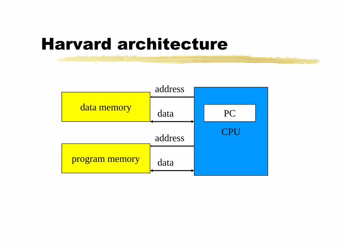
Harvard architecture
PCdata memory
address
data
CPU
program memory
address
data

von Neumann vs. Harvard
�Harvard can’t use self-modifying code.
�Harvard allows two simultaneous memory fetches.fetches.
�Most DSPs use Harvard architecture for streaming data:
greater memory bandwidth;
more predictable bandwidth.

RISC vs. CISC
�Complex instruction set computer (CISC):
many addressing modes;
many operations.many operations.
�Reduced instruction set computer (RISC):
load/store;
pipelinable instructions.

Instruction set
characteristics
�Fixed vs. variable length.
�Addressing modes.
�Number of operands.�Number of operands.
�Types of operands.

Programming model
�Programming model: registers visible to the programmer.
�Some registers are not visible (IR).�Some registers are not visible (IR).

Multiple implementations
�Successful architectures have several implementations:
varying clock speeds;
different bus widths;
different cache sizes;
etc.

Assembly language
�One-to-one with instructions (more or less).
�Basic features:�Basic features:
One instruction per line.
Labels provide names for addresses (usually in first column).
Instructions often start in later columns.
Columns run to end of line.

ARM assembly language
example
label1 ADR r4,c
LDR r0,[r4] ; a comment
ADR r4,dADR r4,d
LDR r1,[r4]
SUB r0,r0,r1 ; comment

Pseudo-ops
�Some assembler directives don’t correspond directly to instructions:
Define current address.
Reserve storage.
Constants.

Endianness
�Relationship between bit and byte/word ordering defines endianness:
byte 3 byte 2 byte 1 byte 0 byte 0 byte 1 byte 2 byte 3
bit 31 bit 0 bit 0 bit 31
little-endian big-endian

Example: C assignments
(ARM Processor)
�C: x = (a + b) - c;
�Assembler:ADR r4,a ; get address for a
LDR r0,[r4] ; get value of a
ADR r4,b ; get address for b, reusing r4
LDR r1,[r4] ; get value of b
ADD r3,r0,r1 ; compute a+b
ADR r4,c ; get address for c
LDR r2,[r4] ; get value of c

C assignment, cont’d.
SUB r3,r3,r2 ; complete computation of x
ADR r4,x ; get address for x
STR r3,[r4] ; store value of x

Example: C assignments
(SHARC DSP)
�C:x = (a + b) - c;
�Assembler:�Assembler:R0 = DM(_a) ! Load a
R1 = DM(_b); ! Load b
R3 = R0 + R1;
R2 = DM(_c); ! Load c
R3 = R3-R2;
DM(_x) = R3; ! Store result in x

Universität Dortmund
Algorithmic level: Example:-MPEG-4 full motion search -
for (z=0; z<20; z++)for (x=0; x<36; x++) {x1=4*x;for (y=0; y<49; y++) {y1=4*y;for (k=0; k<9; k++) {x2=x1+k-4;for (l=0; l<9; ) {y2=y1+l-4;
- 36 - P. Marwedel, Univ. Dortmund, Informatik 12, 04/05
for (l=0; l<9; ) {y2=y1+l-4;for (i=0; i<4; i++) {x3=x1+i; x4=x2+i;for (j=0; j<4;j++) {y3=y1+j; y4=y2+j;if (x3<0 || 35<x3||y3<0||48<y3)then_block_1; else else_block_1;
if (x4<0|| 35<x4||y4<0||48<y4)then_block_2; else else_block_2;
}}}}}}

Universität Dortmund
Instruction level
Algorithms have already been compiled for the instruction set of the processor(s) to be used. Simulations at thislevel allow counting the executed number of instructions.Variations: Simulation only the effect of instructions
- 37 - P. Marwedel, Univ. Dortmund, Informatik 12, 04/05
Simulation only the effect of instructionsTransaction-level modeling : each read/write is onetransaction, instead of a set of signal assignments
Cycle-true simulations : exact number of cyclesBit-true simulations: simulations using exactly the correct number of bits

Universität Dortmund
Instruction level: example
Assembler (MIPS) Simulated semanticsand $1,$2,$3 Reg[1]:=Reg[2] ∧∧∧∧ Reg[3]
or $1,$2,$3 Reg[1]:=Reg[2] ∨∨∨∨ Reg[3]
- 38 - P. Marwedel, Univ. Dortmund, Informatik 12, 04/05
or $1,$2,$3 Reg[1]:=Reg[2] ∨∨∨∨ Reg[3]
andi $1,$2,100 Reg[1]:=Reg[2] ∧∧∧∧ 100
sll $1,$2,10 Reg[1]:=Reg[2] << 10
srl $1,$2,10 Reg[1]:=Reg[2] >> 10

Universität Dortmund
Register transfer level (RTL)
At this level, we model all the components at the register-transfer level, includingarithmetic/logic units (ALUs),registers,memories,
- 39 - P. Marwedel, Univ. Dortmund, Informatik 12, 04/05
memories,muxes anddecoders.Models at this level are always cycle-true.Automatic synthesis from such models is not a major challenge.

Universität Dortmund
Register transfer level: example (MIPS)
Controller
BP
C
Inst
ruct
ion
regi
ster
IR
Mem
ory
Spe
iche
r ALU
00
01 1
§
31:26
25:21
i2
a2
a1
PC
Sou
rce
Targ
etW
rite
ALU
Op
ALU
Sel
A
ALU
Sel
B
Reg
Writ
e
Reg
Des
t
IRW
rite
Mem
Rea
d
Mem
Writ
e
PC
Writ
e
- 40 - P. Marwedel, Univ. Dortmund, Informatik 12, 04/05
Inst
ruct
ion
regi
ster
IR
Mem
ory
Spe
iche
r
T
sign_extend
4
*
ALU
Reg0
0
0
0
1
1
1
1
2
2
3
25:21
20:16
25:0
15:0
15:11
i2
a2
a1
i3
a3
a
2
a1
*§31: 28
"00“

Universität Dortmund
Gate-level models
Models contain gates as the basic components.Provide accurate information about signal transition
probabilities and can therefore also be used for power estimations.
Delay calculations can be more precise than for the RTL.
- 41 - P. Marwedel, Univ. Dortmund, Informatik 12, 04/05
Delay calculations can be more precise than for the RTL. Typically no information about the length of wires (still estimates).
Term sometimes also employed to denote Boolean functions (No physical gates; only considering the behavior of the gates).Such models should be called “Boolean function models”.

Universität Dortmund
Gate-level models: Example
- 42 - P. Marwedel, Univ. Dortmund, Informatik 12, 04/05
source: http://geda.seul.org/screenshots/screenshot-schem2.png