
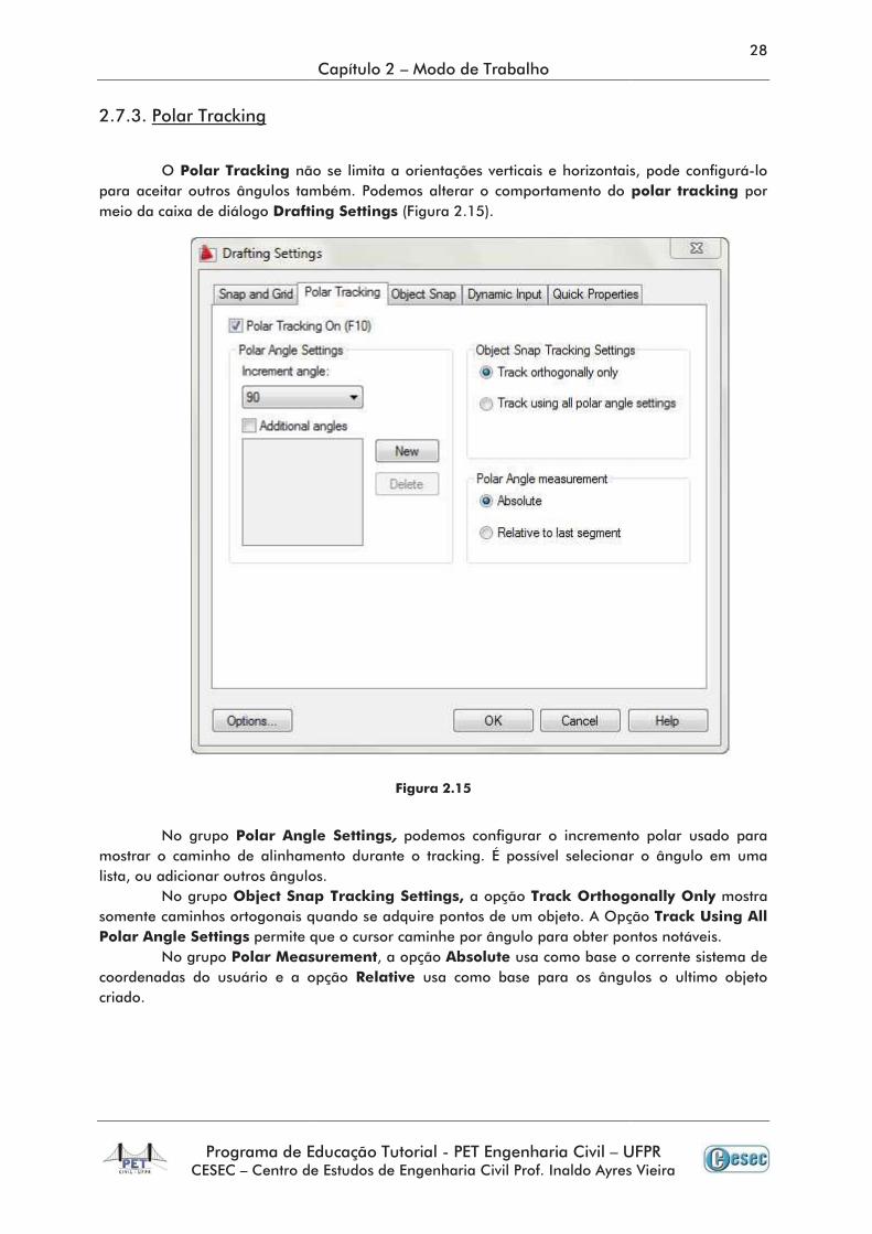
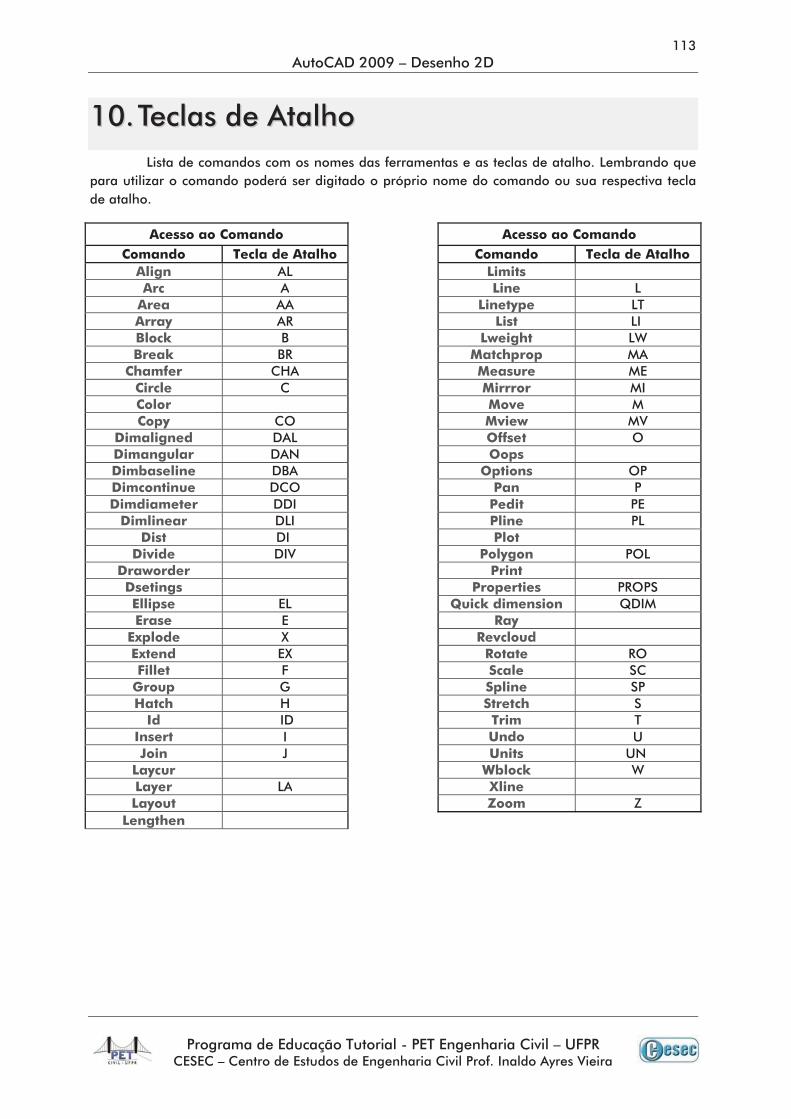
Apostila AutoCAD 2009 Finalizada - WordPress.com · À ,qwurgxomr 3urjudpd gh (gxfdomr 7xwruldo 3(7...
125
3(7 (1*(1+$5,$ &,9,/ ² 8)35 $872'(6. $872&$' '(6(1+2 ' ² 0Ð'8/2 ,17(50(',É5,2 $872&$'
Transcript of Apostila AutoCAD 2009 Finalizada - WordPress.com · À ,qwurgxomr 3urjudpd gh (gxfdomr 7xwruldo 3(7...

↵
↵ ↵
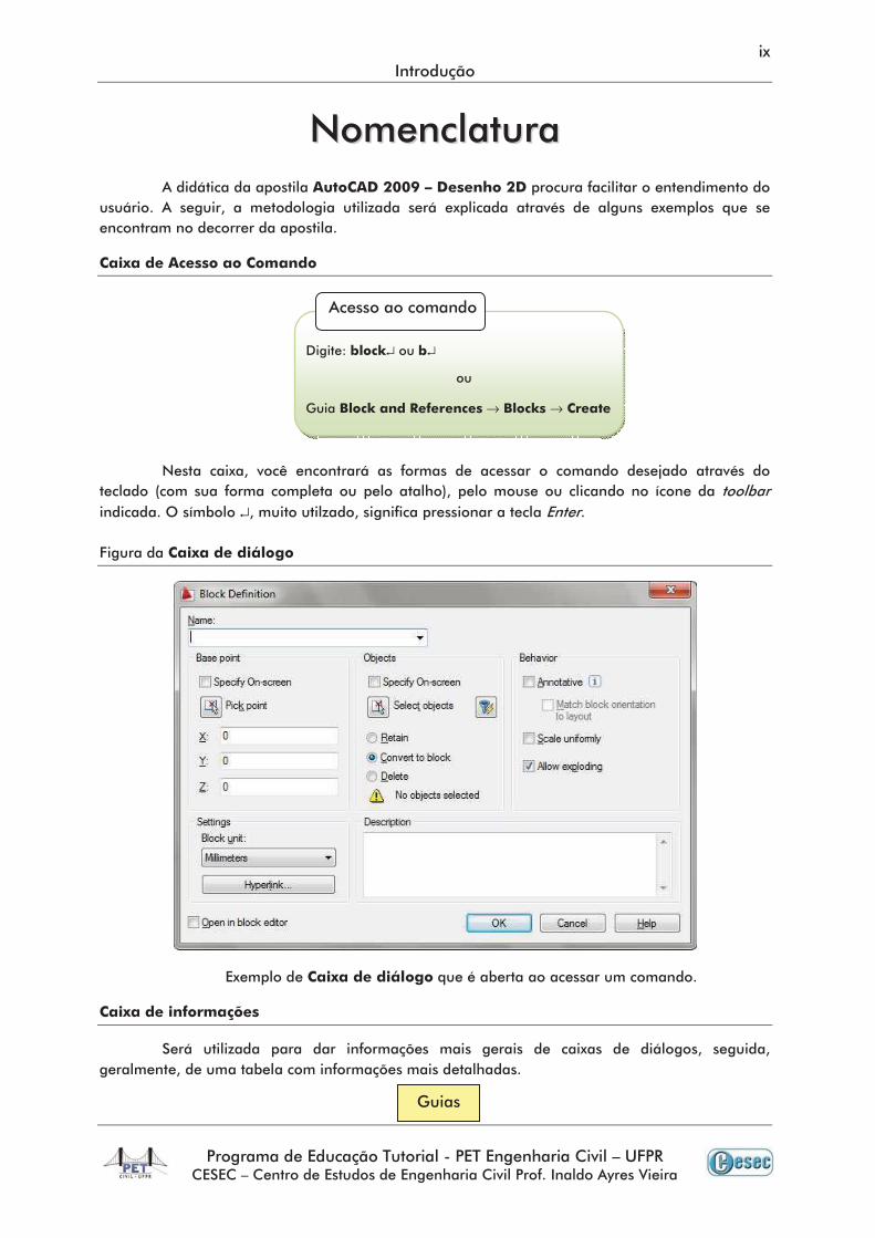
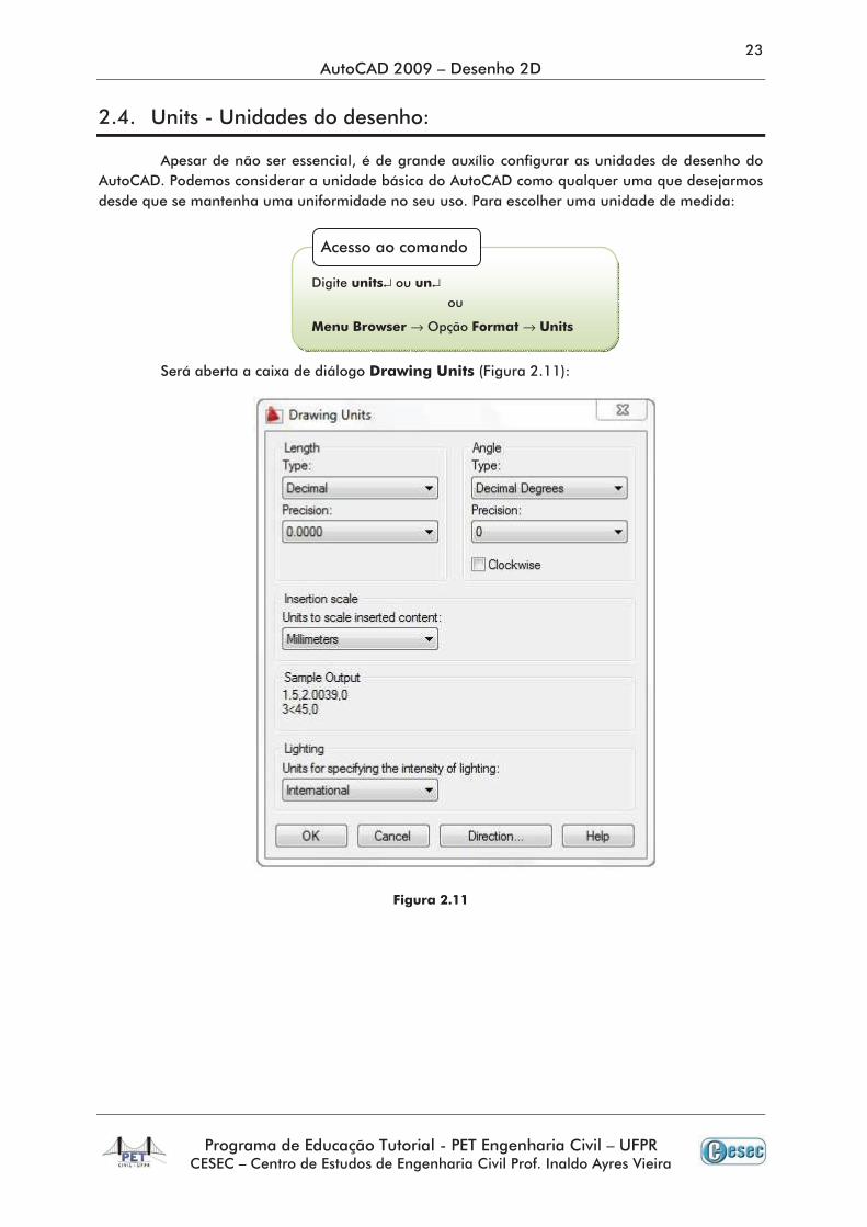
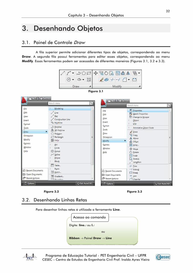
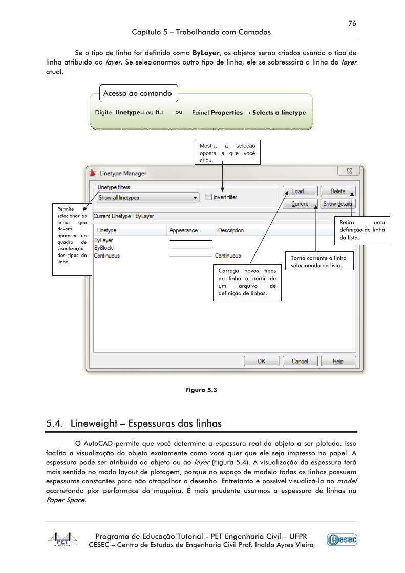
→ →
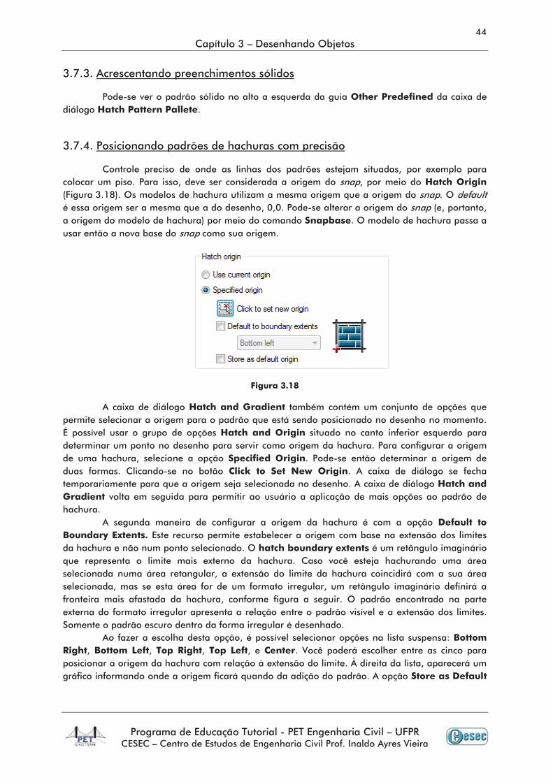
→ →
→ →→ →
↵ ↵
→ →
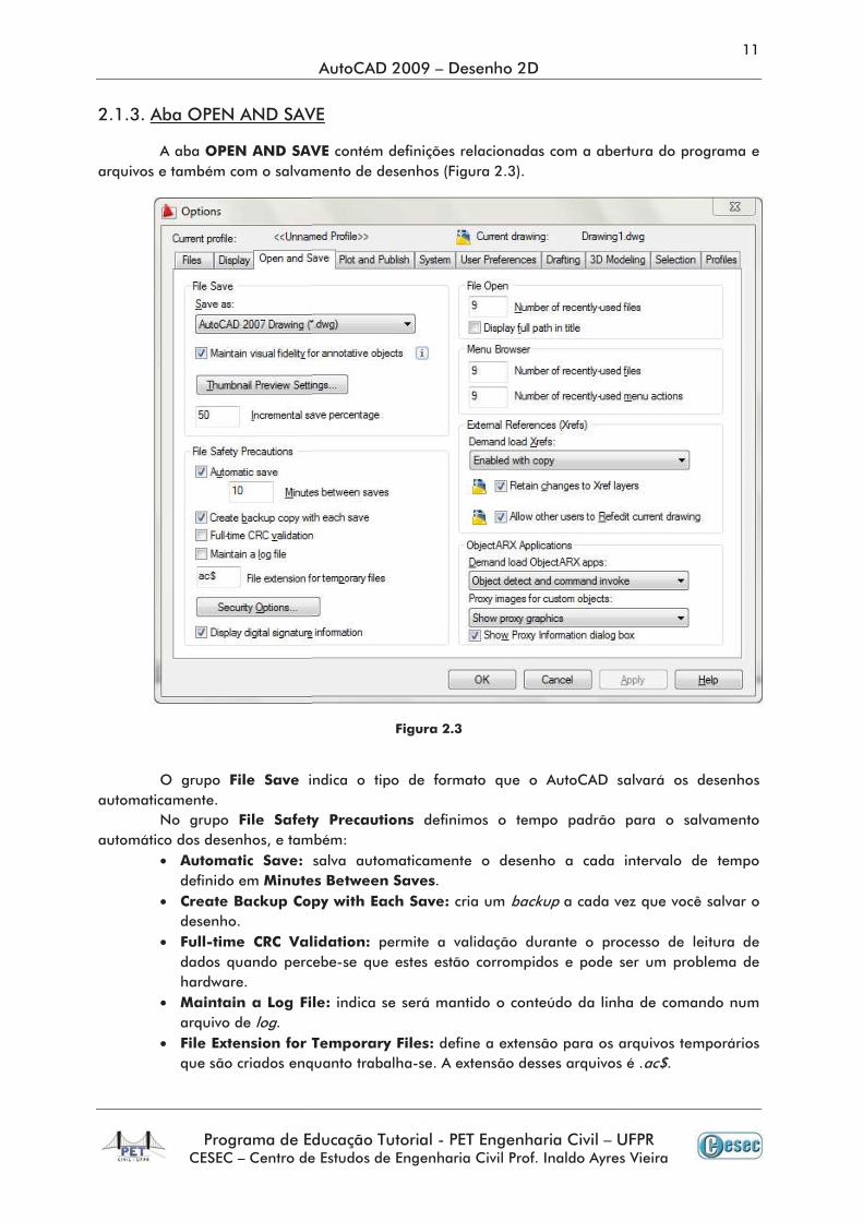
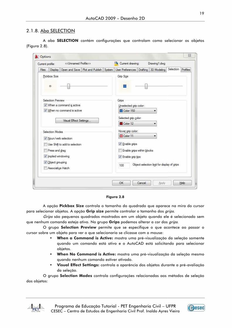
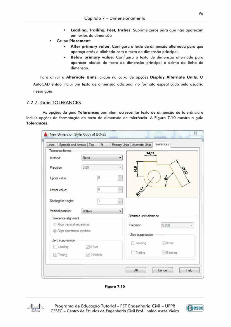
•
•
•
•
•
••
•
•
•
•
° ° ° °
Command: LINE ↵
Specify first point: 10, 20 ;
Specify next point or [Undo]: 40, 40 ;
Specify next point or [Undo]: ↵
Command: LINE ↵
Specify first point: 10,20 ;
Specify next point or [Undo]: @40,40 ;
Specify next point or [Undo]: ↵
→ →
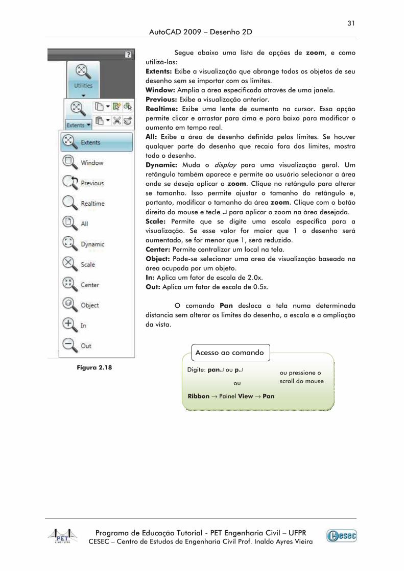
↵ ↵
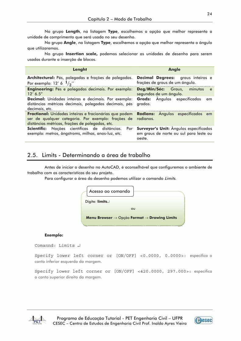
Comannd: Limits ↵
Specify lower left corner or [ON/OFF] <0.0000, 0.0000>:
Specify lower left corner or [ON/OFF] <420.0000, 297.000>:
↵
→ →

↵
→ →
↵ ↵
→ →
↵
↵ ↵
→ →
↵ ↵
→ →
Command: LINE ↵
Specify first point: ;
Specify next point or [Undo]: ;
Specify next point or [Undo]: ↵ ; ↵ ↵
↵ ↵
→
↵
Command: Circle ↵
Specify center point for circle or [3P/2P/Ttr (tan tan radius)]: ;
Specify radius of circle or [Diameter]: ;
↵
Command: Circle ↵
Specify center point for circle or [3P/2P/Ttr (tan tan radius)]: ;
Specify radius of circle or [Diameter]: D ↵ ;
↵
Command: Circle ↵
Specify center point for circle or [3P/2P/Ttr (tan tan radius)]: 2P
↵
Specify first end point of circle's diameter: ;
Specify second end point of circle's diameter: ;
Command: Circle ↵
Specify center point for circle or [3P/2P/Ttr (tan tan radius)]: 3P
↵ ;
Specify first point on circle: ;
Specify second point on circle: ;
Specify third point on circle: ;
Command: Circle ↵
Specify center point for circle or [3P/2P/Ttr (tan tan radius)]: ttr
↵
Specify point on object for first tangent of circle: ;
Specify point on object for second tangent of circle: ;
Specify radius of circle: ;
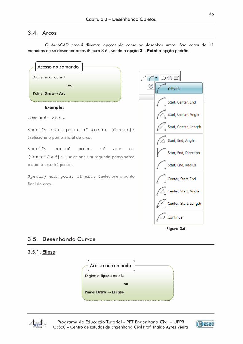
Command: Arc ↵
Specify start point of arc or [Center]:
;
Specify second point of arc or
[Center/End]: ;
Specify end point of arc: ;
↵ ↵
→
↵ ↵
→
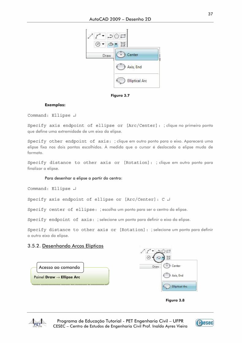
Command: Ellipse ↵
Specify axis endpoint of ellipse or [Arc/Center]: ;
Specify other endpoint of axis: ;
Specify distance to other axis or [Rotation]: ;
Command: Ellipse ↵
Specify axis endpoint of ellipse or [Arc/Center]: C ↵
Specify center of ellipse: ;
Specify endpoint of axis: ;
Specify distance to other axis or [Rotation]: ;
→
Command: Ellipse ↵
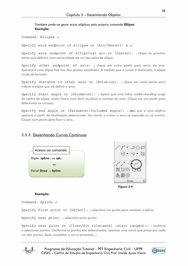
Specify axis endpoint of ellipse or [Arc/Center]: A ↵
Specify axis endpoint of elliptical arc or [Center]: ;
Specify other endpoint of axis: ;
Specify distance to other axis or [Rotation]: ;
Specify start angle or [Parameter]: ;
Specify end angle or [Parameter/Included angle]: ;
Command: Spline ↵
Specify first point or [Object]: ;
Specify next point: ;
Specify next point or [Close/Fit tolerance] <start tangent>: ;
↵
↵ ↵
→
Specify start tangent: ; ↵
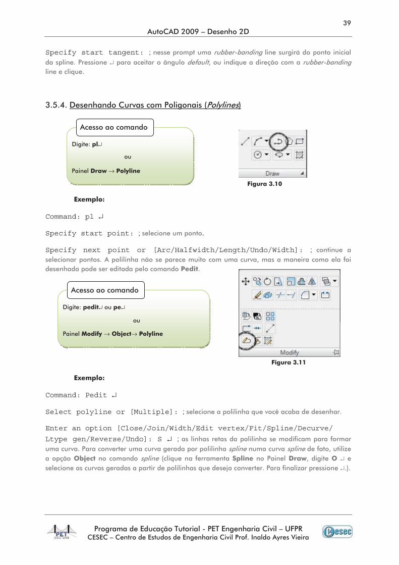
Command: pl ↵
Specify start point: ;
Specify next point or [Arc/Halfwidth/Length/Undo/Width]: ;
Command: Pedit ↵
Select polyline or [Multiple]: ;
Enter an option [Close/Join/Width/Edit vertex/Fit/Spline/Decurve/
Ltype gen/Reverse/Undo]: S ↵ ;
↵↵
↵
→
↵ ↵
→ →
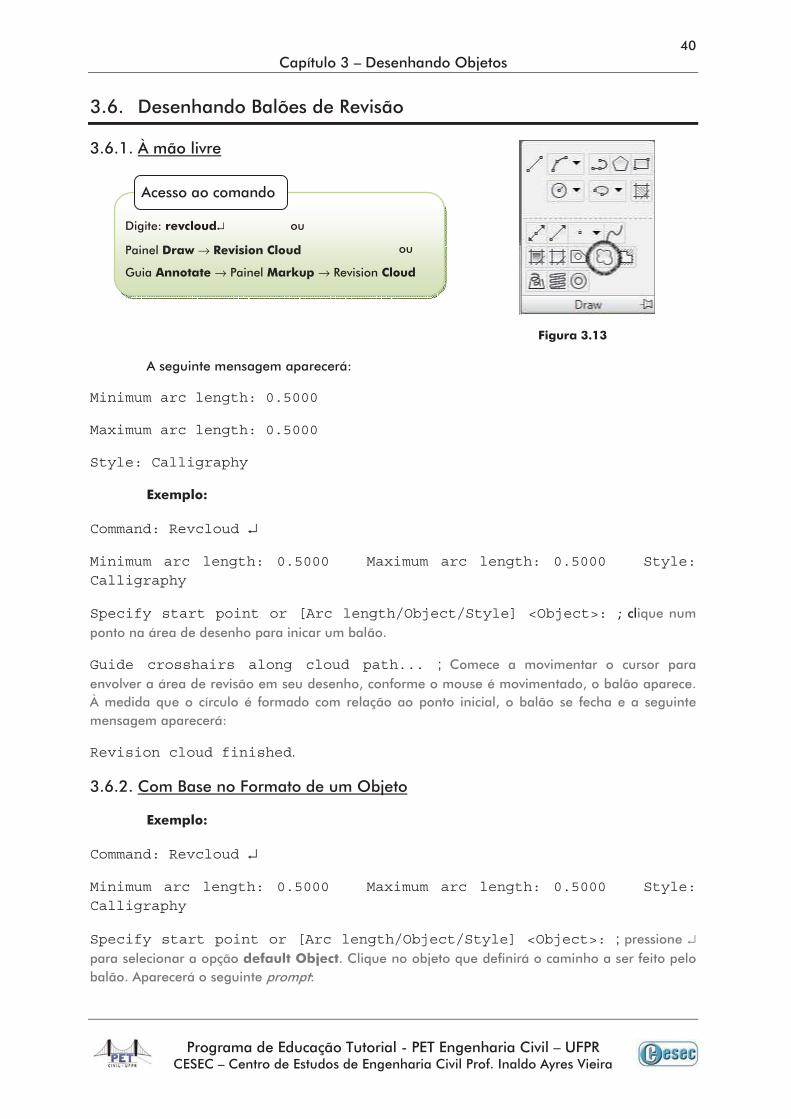
Minimum arc length: 0.5000
Maximum arc length: 0.5000
Style: Calligraphy
Command: Revcloud ↵
Minimum arc length: 0.5000 Maximum arc length: 0.5000 Style: Calligraphy
Specify start point or [Arc length/Object/Style] <Object>:
Guide crosshairs along cloud path... ;
Revision cloud finished.
Command: Revcloud ↵
Minimum arc length: 0.5000 Maximum arc length: 0.5000 Style: Calligraphy
Specify start point or [Arc length/Object/Style] <Object>: ; ↵
↵
→
→ →
Reverse direction [Yes/No]: ; ↵
Command: Revcloud ↵
Minimum arc length: 0.5000 Maximum arc length: 0.5000 Style:
Calligraphy
Specify start point or [Arc length/Object/Style] <Object>: A ↵
Specify minimum length of arc <0.5000>: ;
Specify maximum length of arc <0.5000>: ; ↵
Command: Revcloud ↵
Minimum arc length: 0.5000 Maximum arc length: 0.5000 Style:
Calligraphy
Specify start point or [Arc length/Object/Style] <Object>: S ↵
Select arc style [Normal/Calligraphy]<Normal>: ; ↵
Arc style = Calligraphy ;
↵ ↵
→
↵
Pick or press Esc to return to dialog r <Right-click
to accept hatch>
↵
Command: Pol ↵
POLYGON Enter number of sides <4>: ;
↵
→
↵
→
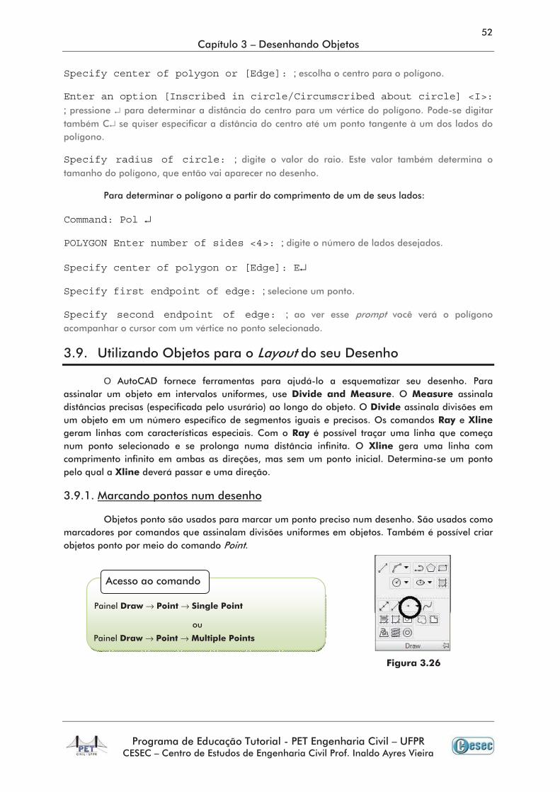
Specify center of polygon or [Edge]: ;
Enter an option [Inscribed in circle/Circumscribed about circle] <I>: ; ↵
↵
Specify radius of circle: ;
Command: Pol ↵
POLYGON Enter number of sides <4>: ;
Specify center of polygon or [Edge]: E↵
Specify first endpoint of edge: ;
Specify second endpoint of edge: ;
O
→ →
→ →
→
→↵
.
↵
→ →
Command: Divide ↵
Select object to divide: ;
Enter the number of segments or [Block]: ;
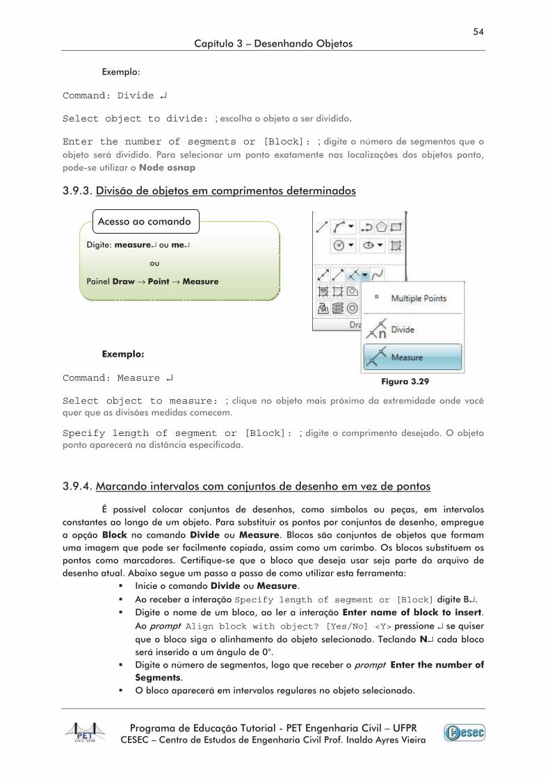
Command: Measure ↵
Select object to measure: ;
Specify length of segment or [Block]: ;
Specify length of segment or [Block] ↵
Align block with object? [Yes/No] <Y> ↵↵
↵ ↵
→ →
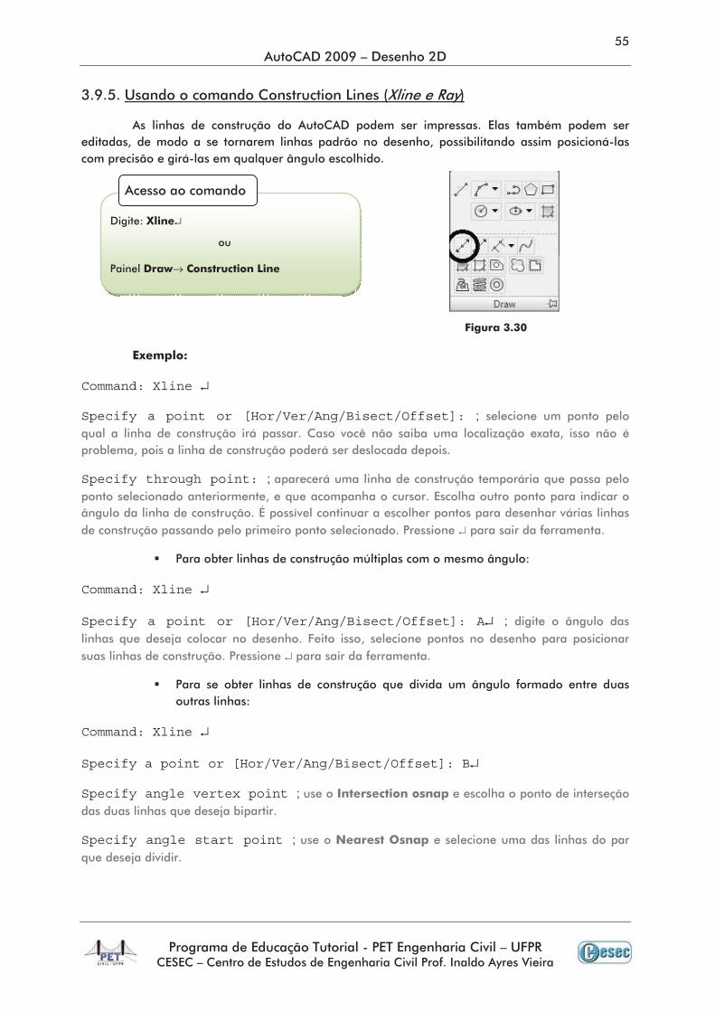
Command: Xline ↵
Specify a point or [Hor/Ver/Ang/Bisect/Offset]: ;
Specify through point: ;
↵
Command: Xline ↵
Specify a point or [Hor/Ver/Ang/Bisect/Offset]: A↵ ;
↵
Command: Xline ↵
Specify a point or [Hor/Ver/Ang/Bisect/Offset]: B↵
Specify angle vertex point ;
Specify angle start point ;
↵
→
Specify angle end point ;
Command: Xline ↵
Specify a point or [Hor/Ver/Ang/Bisect/Offset]: O↵
Specify offset distance or [Through] <Through>: ;
Select a line object ;
Specify side to offset ;
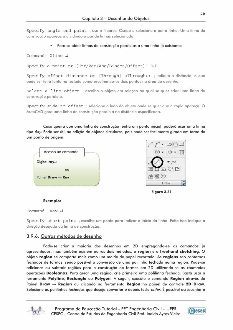
Command: Ray ↵
Specify start point ;
→
↵
→
↵
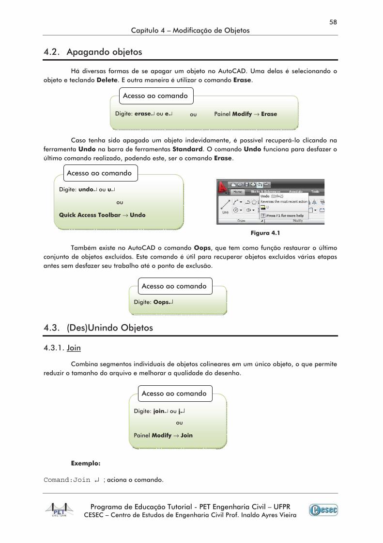
Comand:Join ↵ ;
↵ ↵ →
↵ ↵
→
↵
↵ ↵
→
Select source object: ;
Select lines to join to source: ;
Select lines to join to source: ;
Select objects to join to source: ;
Select arcs to join to source or [cLose]: ;
Select elliptical arcs to join to source or [cLose]: ;
Select splines to join to source: ;
Command:Break ↵ ;
Select object: ;
Specify second break point or [First point]: ; ↵
Specify first break point: ;
Specify second break point: ; ↵
↵ ↵
→
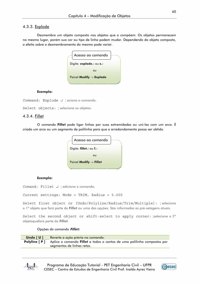
Command: Explode ↵ ; .
Select objects: ;
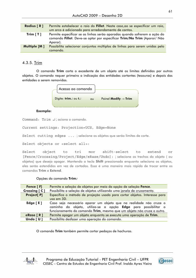
Comand: Fillet ↵ ;
Current settings: Mode = TRIM, Radius = 5.000
Select first object or [Undo/Polyline/Radius/Trim/Multiple]: ;
Select the second object or shift-select to apply corner: ;
↵ ↵
→
↵ ↵
→
Command: Trim ↵ ;
Current settings: Projection=UCS, Edge=None
Select cutting edges ... ;
Select objects or <select all>:
Select object to tri mor shift-select to extend or [Fence/Croossing/Project/Edge/eRase/Undo]: ;
↵ ↵ →
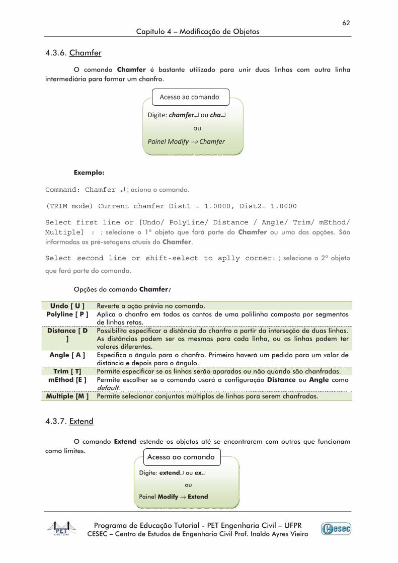
Command: Chamfer ↵ ;
(TRIM mode) Current chamfer Dist1 = 1.0000, Dist2= 1.0000
Select first line or [Undo/ Polyline/ Distance / Angle/ Trim/ mEthod/ Multiple] : ;
Select second line or shift-select to aplly corner: ;
↵ ↵
→
↵ ↵
→
Command: Extend ↵ ;
Current settings: Projection=UCS, Edge=None
Select boundary edges...
Select objects or < select all >: ;
Select object to extend or shift-select to tri mor [Fence/Crossing/Project/Edge/Undo]: ;
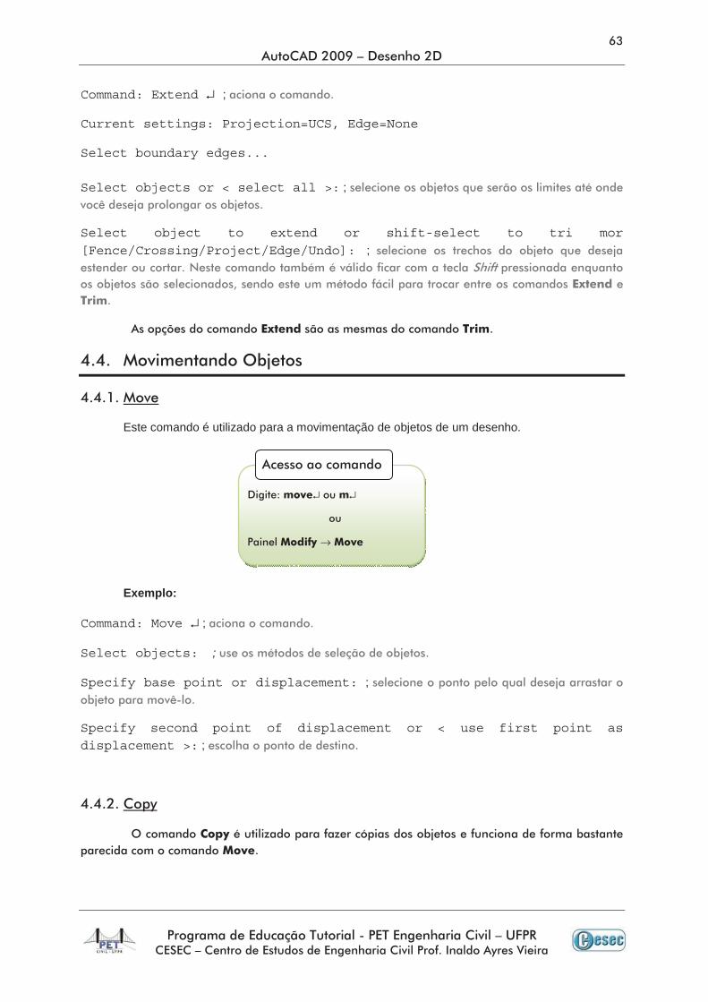
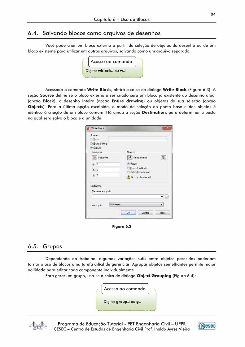
Este comando é utilizado para a movimentação de objetos de um desenho.
Exemplo:
Command: Move ↵ ;
Select objects: ;
Specify base point or displacement: ;
Specify second point of displacement or < use first point as displacement >: ;
↵ ↵
→
Command: Copy ↵ ;
Select objects: ;
Specify base point or [ Displacement ]: ;
Specify second point or <use first point as displacement>: ;
Specify second point or [Exit/Undo] <Exit>: ; ↵
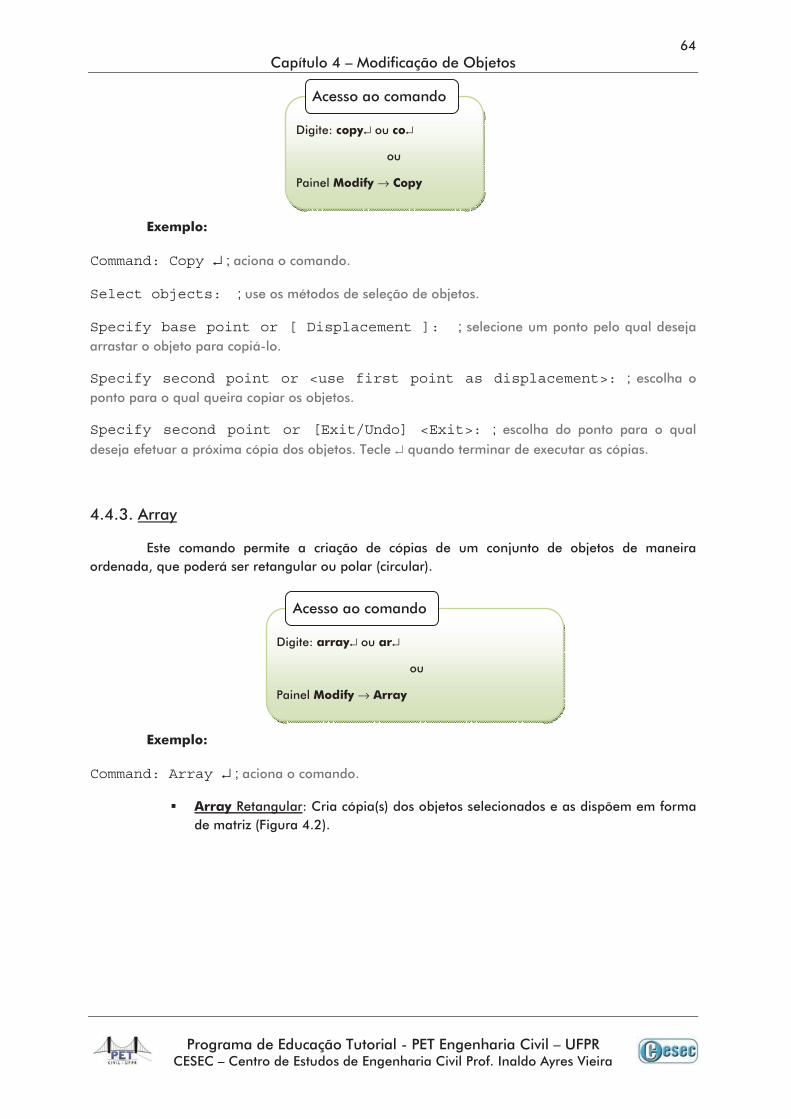
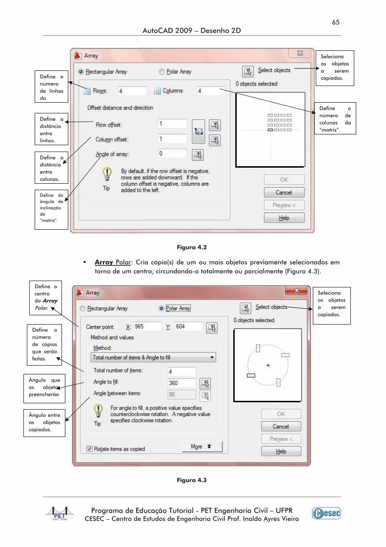
Command: Array ↵ ;
↵ ↵
→
↵ ↵
→
Command: Offset ↵ ;
Current settings: Erase source= No Layer= Source OFFSETGAPTYPE=0
Specify Offset distance or [Through/Erase/Layer] <Through>: ;↵
Select object to offset or [Exit/Undo] <Exit>: ;
Specify point on side to offset or [Exit/Multiple/Undo] <Exit>: ;
Command: Mirror ↵ ;
Select the objects: ;
Specify first point of mirror line: ;
↵ ↵
→
↵ ↵
→
Specify second point os mirror line: ;
Delete source objects? [Yes/No] <No>: ;
Command: Scale ↵ ;
Select objects: ;
Specify base point ;
Specify scale factor or [Copy/Reference]: ;
↵ ↵
→
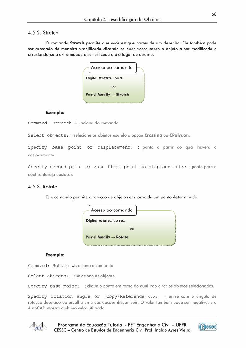
Command: Stretch ↵ ;
Select objects: ;
Specify base point or displacement: ;
Specify second point or <use first point as displacement>: ;
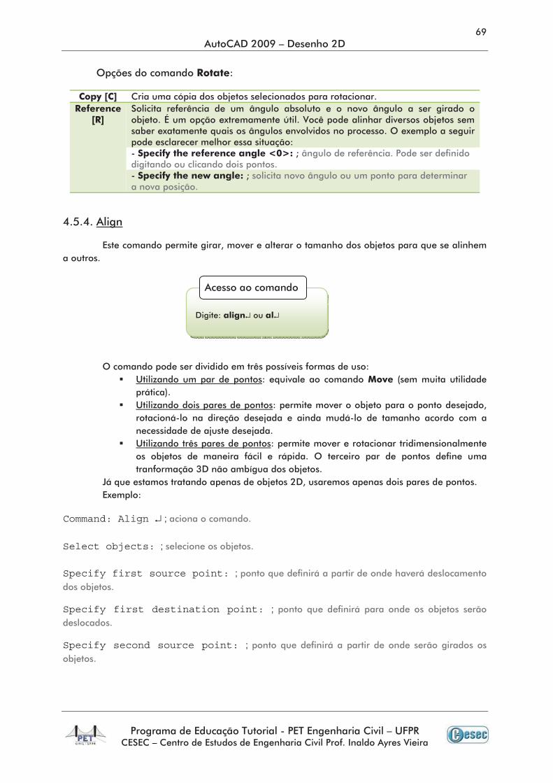
Command: Rotate ↵ ;
Select objects: ;
Specify base point: ;
Specify rotation angle or [Copy/Reference]<0>: ;
↵ ↵
→
↵ ↵
→
Command: Align ↵ ;
Select objects: ;
Specify first source point: ;
Specify first destination point: ;
Specify second source point: ;
↵ ↵
Specify second destination point: ;
Specify third source point or <continue>: ; ↵
Scale objects based on alignment points? [Yes/No]: ;
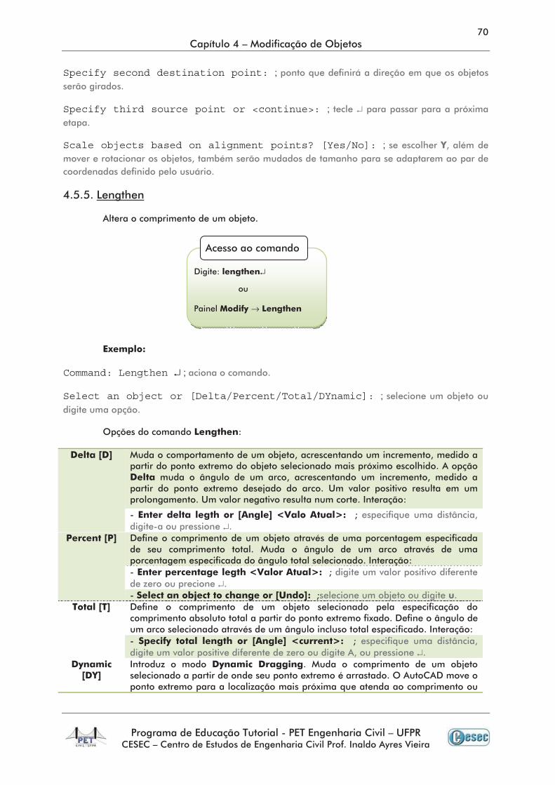
Command: Lengthen ↵ ;
Select an object or [Delta/Percent/Total/DYnamic]: ;
↵
↵
↵
↵
→
↵
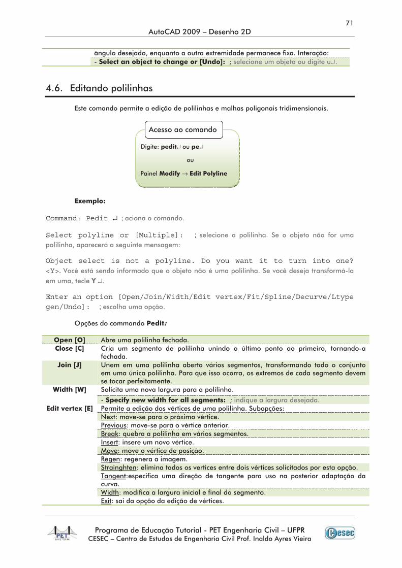
Command: Pedit ↵ ;
Select polyline or [Multiple]: ;
Object select is not a polyline. Do you want it to turn into one? <Y>.
↵
Enter an option [Open/Join/Width/Edit vertex/Fit/Spline/Decurve/Ltype gen/Undo]: ;
↵ ↵
→
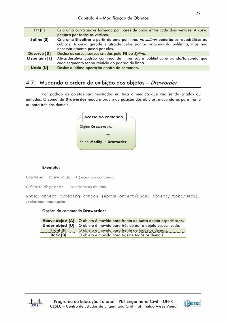
Command: Draworder ↵ ;
Select objects: ;
Enter object ordering option [Above object/Under object/Front/Back]:;
↵
→
↵ ↵
→
↵
→
↵ ↵ →
Mostra a seleção oposta a que você criou.
↵ ↵
→
↵
→ →
↵ ↵
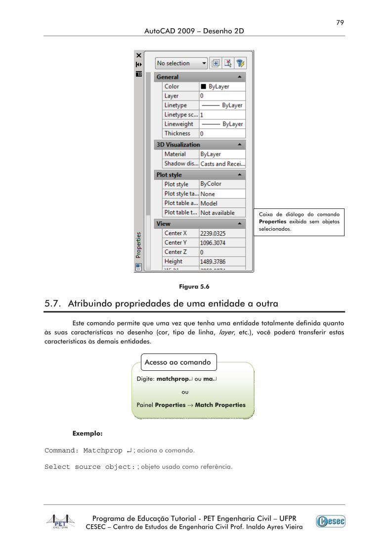
Command: Matchprop ↵ ;
Select source object: ;
↵ ↵
→
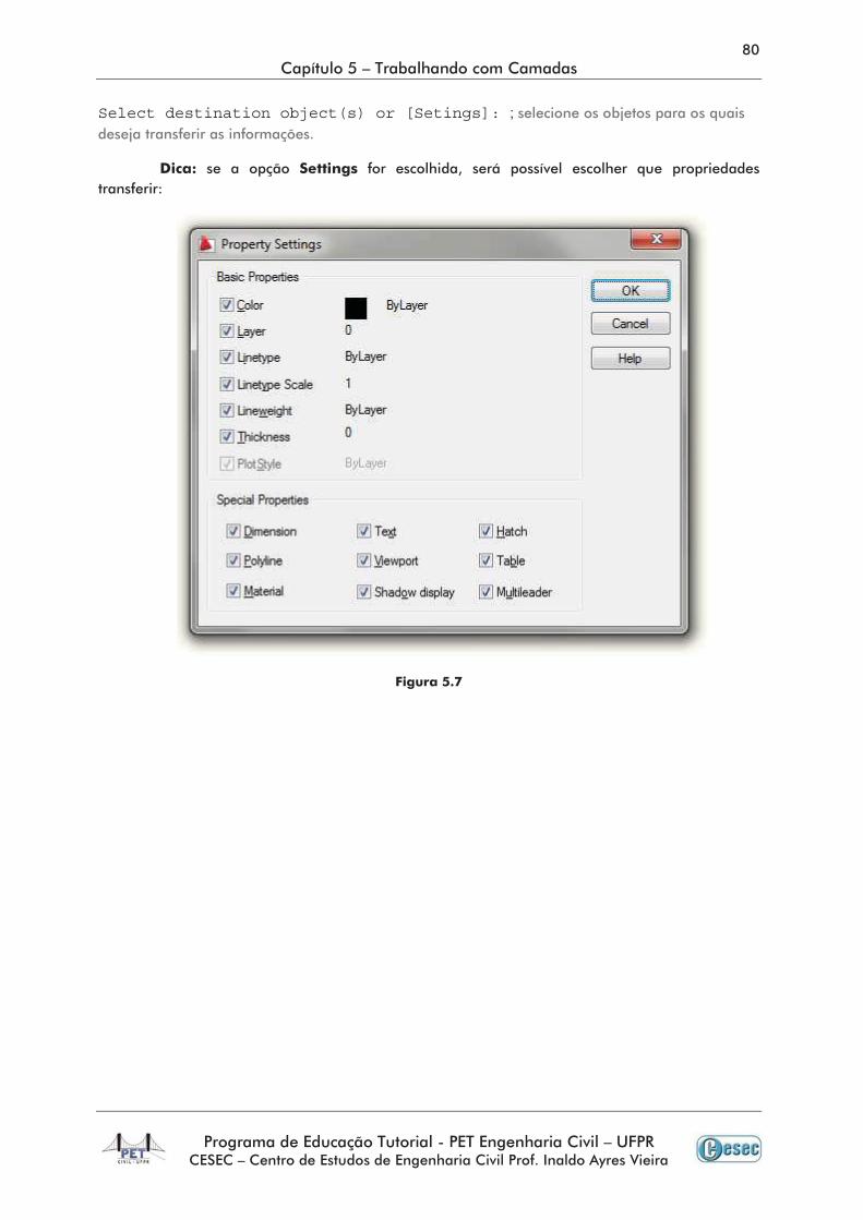
Select destination object(s) or [Setings]: ;
↵
↵ ↵ → →
↵ ↵
→ →
↵ → →
↵ ↵
↵ ↵
↵ ↵
→ →
••••
•
•
••••
•
•
•
•
•
•
•••
•
•
•
•
••••
•
•
•
•
•
•
•
•
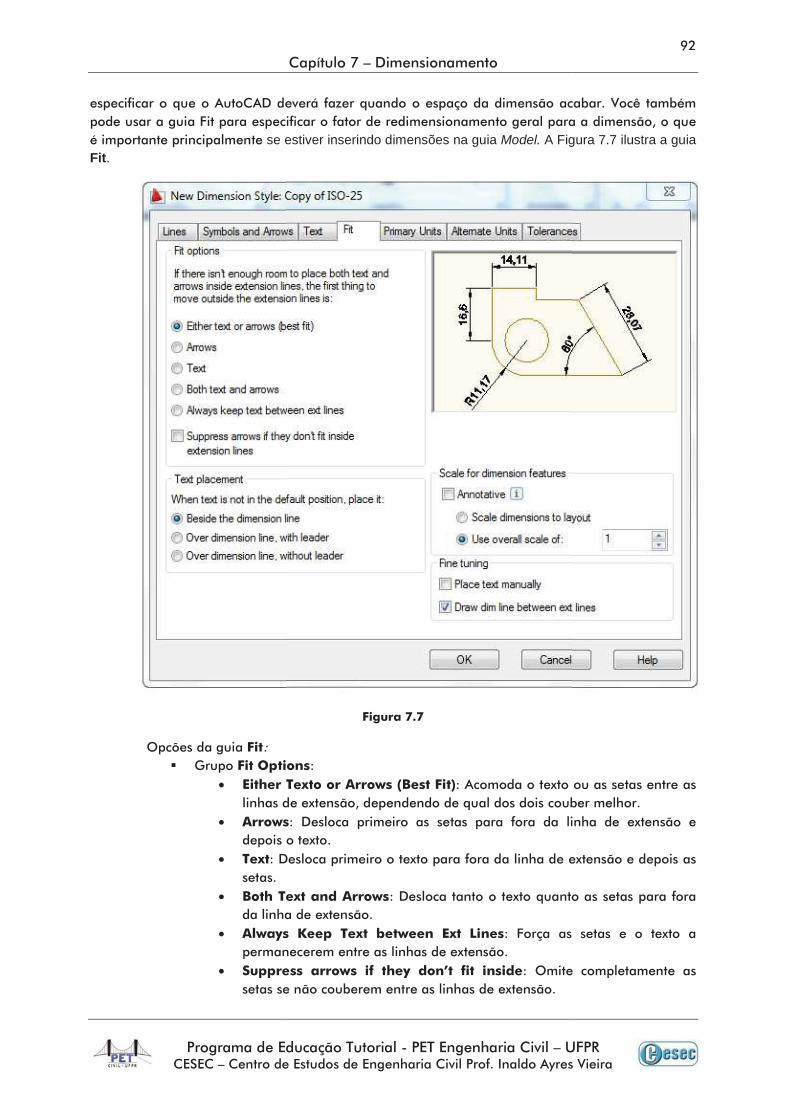
se eFit.
•
•
•
•
•
•
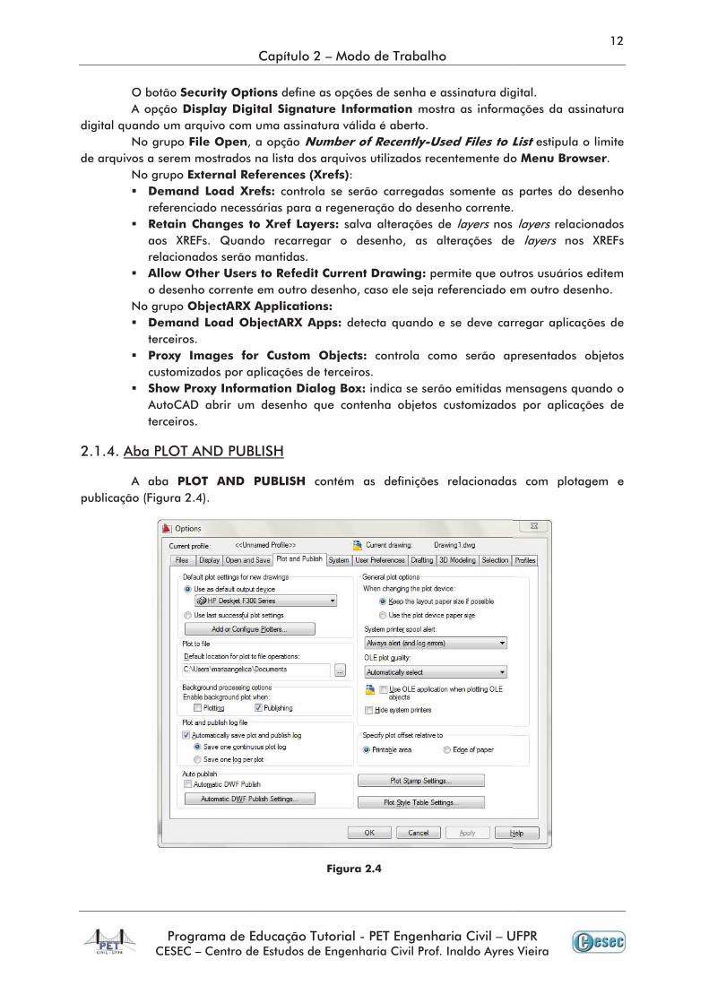
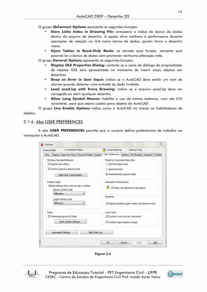
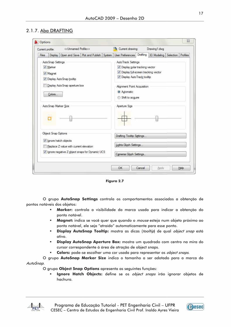
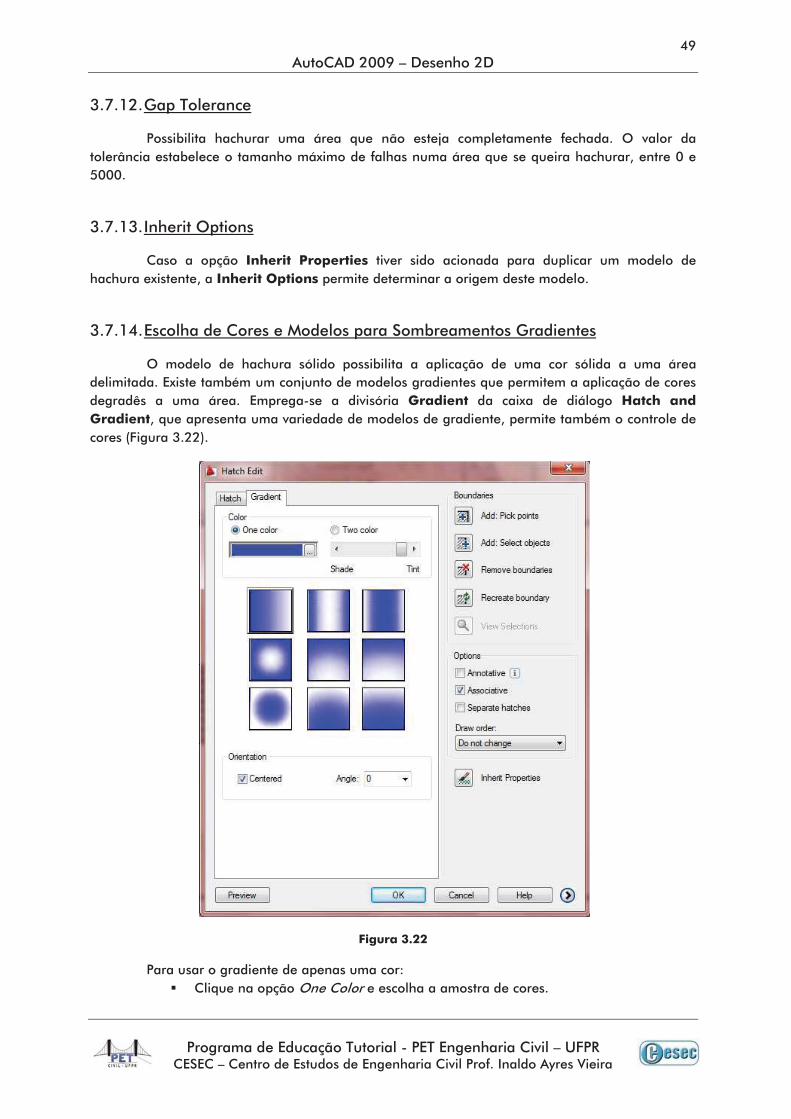
estiver inserindo dimensões na guia Model. A Figgura 7.7 ilustra a guia
•
•
•
•
•
•
•
•
•
•
•
•
•
•
•
•
•
•
•
••
•
•
•
•
•
•
•
•
.
•
•
•
•
•
•
•
•
•
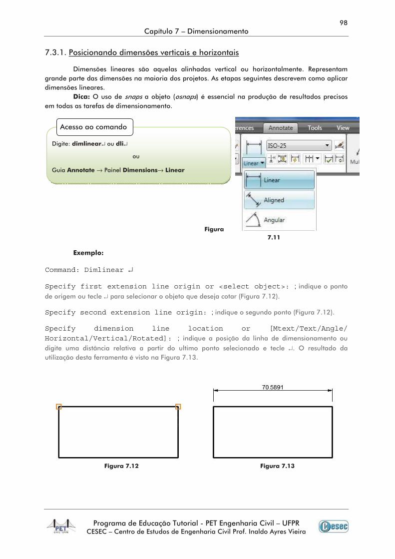
Command: Dimlinear ↵
Specify first extension line origin or <select object>: ; ↵
Specify second extension line origin: ;
Specify dimension line location or [Mtext/Text/Angle/ Horizontal/Vertical/Rotated]: ;
↵
↵ ↵
→ →
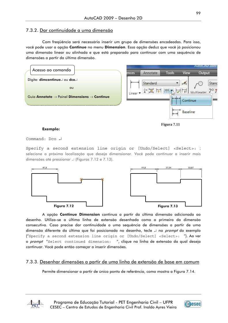
Command: Dco ↵
Specify a second extension line origin or [Undo/Select] <Select>: ;
↵
↵Specify a second extension line origin or [Undo/Select] <Select>:
Select continued dimension:
↵ ↵
→ →
Figura 7.11
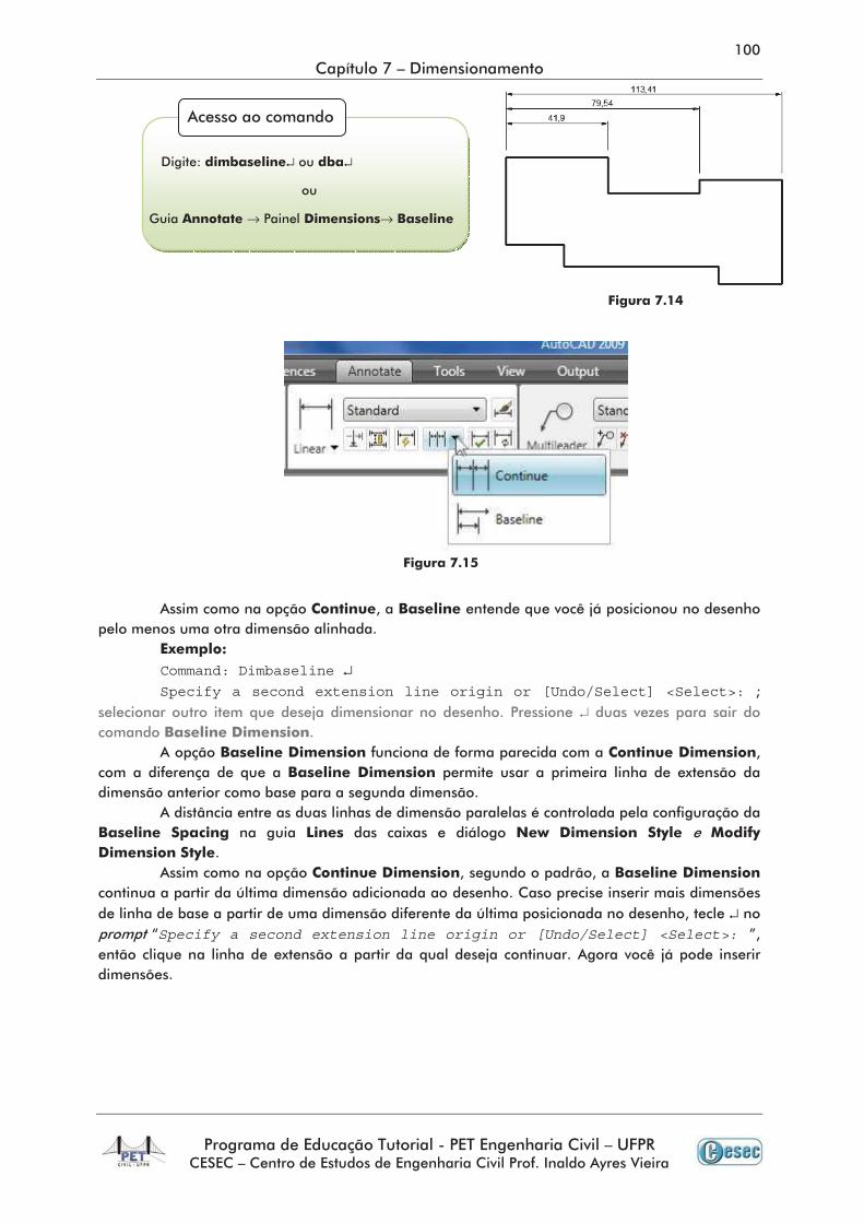
Command: Dimbaseline ↵Specify a second extension line origin or [Undo/Select] <Select>:
↵
↵Specify a second extension line origin or [Undo/Select] <Select>:
↵ ↵
→ →
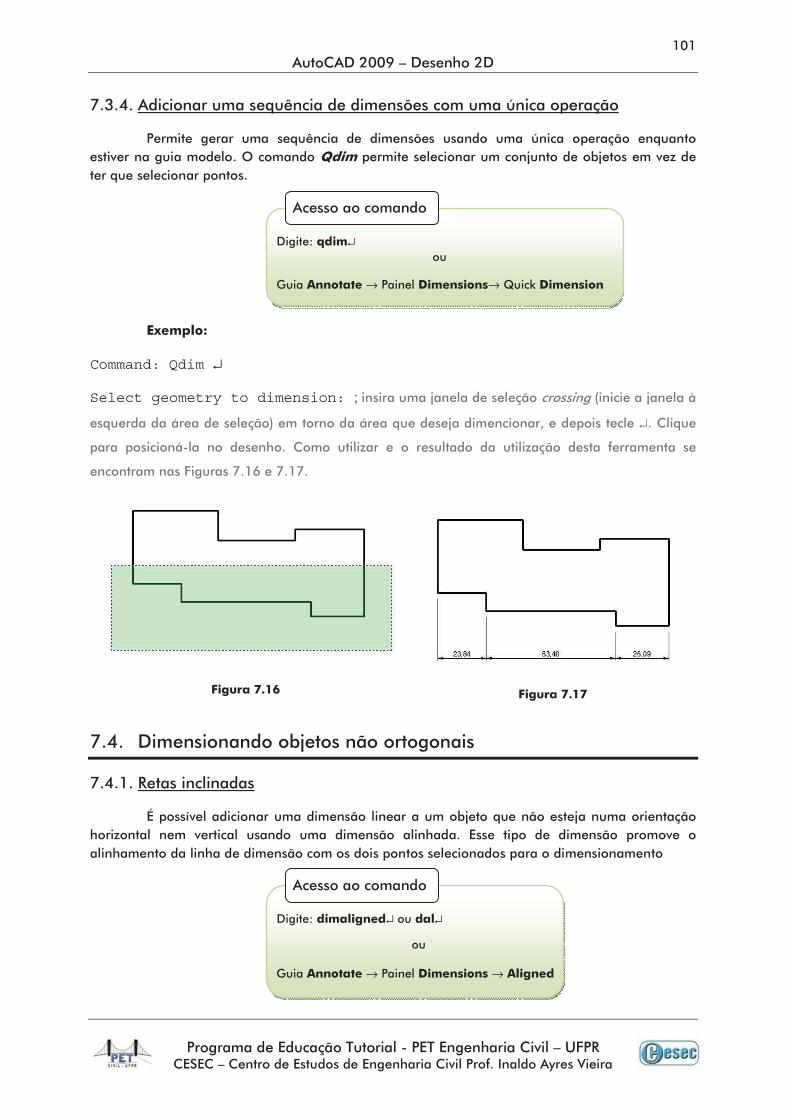
Command: Qdim ↵
Select geometry to dimension: ;
↵
↵
→ →
↵ ↵
→ →
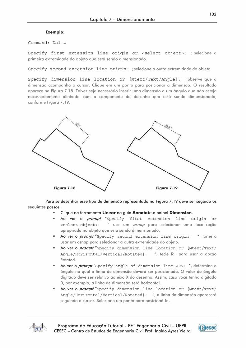
Command: Dal ↵
Specify first extension line origin or <select object>: ;
Specify second extension line origin: ;
Specify dimension line location or [Mtext/Text/Angle]: ;
Specify first extension line origin or
<select object>:
Specify second extension line origin:
Specify dimension line location or [Mtext/Text/
Angle/Horizontal/Vertical/Rotated]: ↵
Specify angle of dimension line <0>:
Specify dimension line location or [Mtext/Text/
Angle/Horizontal/Vertical/Rotated]:
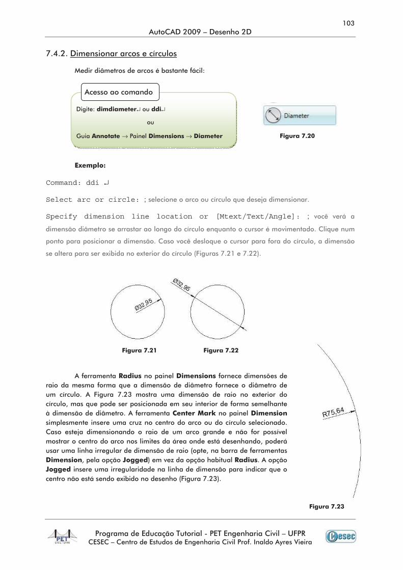
Command: ddi ↵
Select arc or circle: ;
Specify dimension line location or [Mtext/Text/Angle]: ;
↵ ↵
→ →
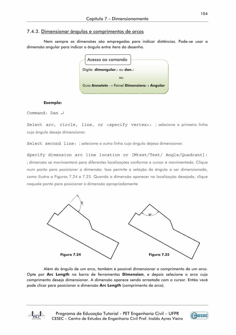
Command: Dan ↵
Select arc, circle, line, or <specify vertex>: ;
Select second line: ;
Specify dimension arc line location or [Mtext/Text/ Angle/Quadrant]:
;
↵ ↵
→ →
↵
Command: Area ↵
Specify first corner point or [Object/Add area/Subtract area]
<Object>: O ↵
Select objects: ;
↵ ↵
→ →
↵
→ →
↵
→ →
↵
→ →
↵
→
→
→
↵ ↵ → →
Command: Zoom ↵Specify corner of window, enter a scale factor (nX or nXP), or [All/Center/Dynamic/Extends/Previous/Scale/Window/Object] <real time>: 1/100XP
Command: Zoom ↵Specify corner of window, enter a scale factor (nX or nXP), or [All/Center/Dynamic/Extends/Previous/Scale/Window/Object]<real time>: 1000/100XP
↵ ↵
→ →
![(',7$/ Q · 2019-08-19 · (vfrod gh (qjhqkduld 6hfuhwduld *hudo $y 3uhvlghqwh $qw{qlr &duorv q %hor +rul]rqwh 0* ± &(3 vhfjhudo#hqj xipj eu ± 7hohirqh (',7$/ q &dsdflwdomr gh 6huylgruhv](https://static.fdocumentos.tips/doc/165x107/5f78d63274802b50c81afe26/7-q-2019-08-19-vfrod-gh-qjhqkduld-6hfuhwduld-hudo-y-3uhvlghqwh-qwqlr.jpg)


![Parte 1 [Modo de Compatibilidade] - UFPR · $oyhqduld (vwuxwxudo-rvp gh $ )uhlwdv -u &rqvwuxomr &lylo ,, &rqvwuxomr &lylo ,, 7& 0lqlvwpulr gd (gxfdomr 8qlyhuvlgdgh )hghudo gr 3dudqi](https://static.fdocumentos.tips/doc/165x107/5c02729009d3f279018e2540/parte-1-modo-de-compatibilidade-oyhqduld-vwuxwxudo-rvp-gh-uhlwdv-u.jpg)

![GH QRYHPEUR GH 'LUHWRU 3UHVLGHQWH 6mR 3DXOR GH IHYHUHLUR GH€¦ · gh vhuylorv rx txh whqkdp lqwhuhvvh hp uhvxowdgr gh surfhvvrv gh olfhqfldphqwr rx uhjxodul]domr dpelhqwdo rx gh](https://static.fdocumentos.tips/doc/165x107/5ec16007d2b2c9169c0ccde1/gh-qryhpeur-gh-luhwru-3uhvlghqwh-6mr-3dxor-gh-ihyhuhlur-gh-gh-vhuylorv-rx-txh-whqkdp.jpg)


![ES I Aula03n [Modo de Compatibilidade] · z)&7 81(63 z z3uri 'u 5rjpulr ( *dufldz %dfkduhodgr hp &lrqfld gd &rpsxwdomr (qjhqkduld gh 6riwzduh , 5rjpulr (gxdugr *dufld](https://static.fdocumentos.tips/doc/165x107/5f1c1cd59c839303844e3af4/es-i-aula03n-modo-de-compatibilidade-z7-8163-z-z3uri-u-5rjpulr-dufldz.jpg)